Distributed volumetric cargo sensor system
Raasch , et al. April 12, 2
U.S. patent number 11,299,219 [Application Number 16/541,419] was granted by the patent office on 2022-04-12 for distributed volumetric cargo sensor system. This patent grant is currently assigned to Spireon, Inc.. The grantee listed for this patent is Spireon, Inc.. Invention is credited to Tim Harvey, Charles F. Raasch.


| United States Patent | 11,299,219 |
| Raasch , et al. | April 12, 2022 |
Distributed volumetric cargo sensor system
Abstract
A cargo detection apparatus installed within a cargo container includes multiple distance sensors and one or more processors in communication with the distance sensors. The distance sensors, which are configured for mounting on or adjacent to a ceiling of the cargo container, generate distance signals. Each distance signal indicates a distance between a corresponding one of the distance sensors and a surface within the interior space of the cargo container. The one or more processors are operable to execute instructions to compare the distance indicated by each of the distance signals to a distance threshold, and generate a cargo-present indication if the distance is less than the distance threshold. The distance sensors may be laser-ranging time-of-flight sensors or ultrasonic sensors.
| Inventors: | Raasch; Charles F. (Foothill Ranch, CA), Harvey; Tim (Temecula, CA) | ||||||||||
|---|---|---|---|---|---|---|---|---|---|---|---|
| Applicant: |
|
||||||||||
| Assignee: | Spireon, Inc. (Irvine,
CA) |
||||||||||
| Family ID: | 69524472 | ||||||||||
| Appl. No.: | 16/541,419 | ||||||||||
| Filed: | August 15, 2019 |
Prior Publication Data
| Document Identifier | Publication Date | |
|---|---|---|
| US 20200055553 A1 | Feb 20, 2020 | |
Related U.S. Patent Documents
| Application Number | Filing Date | Patent Number | Issue Date | ||
|---|---|---|---|---|---|
| 62765256 | Aug 20, 2018 | ||||
| Current U.S. Class: | 1/1 |
| Current CPC Class: | G06Q 50/30 (20130101); G06Q 50/28 (20130101); G01S 17/08 (20130101); B62D 53/06 (20130101); G06Q 10/083 (20130101); G01S 15/08 (20130101); G01S 17/04 (20200101); G06Q 10/087 (20130101); G01S 17/87 (20130101); G01S 17/88 (20130101); G01S 15/88 (20130101); G01S 15/87 (20130101) |
| Current International Class: | B62D 53/06 (20060101); G01S 17/08 (20060101); G01S 15/08 (20060101); G06Q 10/08 (20120101); G01S 17/88 (20060101); G01S 17/04 (20200101) |
References Cited [Referenced By]
U.S. Patent Documents
| 906021 | December 1908 | Herrick |
| 4633407 | December 1986 | Freienstein et al. |
| 4837700 | June 1989 | Ando et al. |
| 5119301 | June 1992 | Shimizu et al. |
| 5289369 | February 1994 | Hirshberg |
| 5299132 | March 1994 | Wortham |
| 5307277 | April 1994 | Hirano |
| 5870029 | February 1999 | Otto et al. |
| 5877956 | March 1999 | Frank et al. |
| 6025774 | February 2000 | Forbes |
| 6240365 | May 2001 | Bunn |
| 6249217 | June 2001 | Forbes |
| 6510381 | January 2003 | Grounds et al. |
| 6512465 | January 2003 | Flick |
| 6701234 | March 2004 | Vogelsang |
| 6771970 | August 2004 | Dan |
| 6816090 | November 2004 | Teckchandani et al. |
| 6930638 | August 2005 | Lloyd et al. |
| 6931309 | August 2005 | Phelan et al. |
| 6985087 | January 2006 | Soliman |
| 7034683 | April 2006 | Ghazarian |
| 7091835 | August 2006 | Boulay et al. |
| 7102510 | September 2006 | Boling et al. |
| 7170390 | January 2007 | Quinones et al. |
| 7174243 | February 2007 | Lightner et al. |
| 7177738 | February 2007 | Diaz |
| 7215282 | May 2007 | Boling et al. |
| 7266378 | September 2007 | Norta et al. |
| 7346439 | March 2008 | Bodin |
| 7366551 | April 2008 | Hartley |
| 7405658 | July 2008 | Richards |
| 7546151 | June 2009 | Hartley |
| 7574195 | August 2009 | Krasner et al. |
| 7593999 | September 2009 | Nathanson |
| 7675423 | March 2010 | Boling et al. |
| 7701363 | April 2010 | Zlojutro |
| 7725216 | May 2010 | Kim |
| 7817033 | October 2010 | Motoyama |
| 7818098 | October 2010 | Koepf et al. |
| 7830305 | November 2010 | Boling et al. |
| 7893818 | February 2011 | Smoyer et al. |
| 7970496 | June 2011 | Koepf et al. |
| 8018332 | September 2011 | Boling et al. |
| 8126601 | February 2012 | Kapp et al. |
| 8237591 | August 2012 | Holcomb et al. |
| 8330626 | December 2012 | Adelson |
| 8330817 | December 2012 | Foster |
| 8368561 | February 2013 | Welch et al. |
| 8452673 | May 2013 | Boling et al. |
| 8462021 | June 2013 | Welch et al. |
| 8510200 | August 2013 | Pearlman et al. |
| 8527135 | September 2013 | Lowrey et al. |
| 8565963 | October 2013 | Burke |
| 8612137 | December 2013 | Harris et al. |
| 8626152 | January 2014 | Farrell et al. |
| 8655544 | February 2014 | Fletcher et al. |
| 8671063 | March 2014 | Ehrman et al. |
| 8725326 | May 2014 | Kapp et al. |
| 8760274 | June 2014 | Boling et al. |
| 8799461 | August 2014 | Herz et al. |
| 8933802 | January 2015 | Baade |
| 8970701 | March 2015 | Lao |
| 9008894 | April 2015 | Bishop et al. |
| 9049564 | June 2015 | Muetzel et al. |
| 9060213 | June 2015 | Jones |
| 9070271 | June 2015 | Baade et al. |
| 9316737 | April 2016 | Baade |
| 9332404 | May 2016 | Boling et al. |
| 9516394 | December 2016 | Carlo et al. |
| 9551788 | January 2017 | Epler |
| 9779379 | October 2017 | Hall et al. |
| 9779449 | October 2017 | Meyer et al. |
| 10089598 | October 2018 | Reeder et al. |
| 10169822 | January 2019 | Jarvis et al. |
| 10223744 | March 2019 | Brady et al. |
| 10232823 | March 2019 | Bobay et al. |
| 10255824 | April 2019 | Pearlman et al. |
| 10311315 | June 2019 | Drazan et al. |
| 2001/0018639 | August 2001 | Bunn |
| 2001/0034577 | October 2001 | Grounds et al. |
| 2002/0000916 | January 2002 | Richards |
| 2002/0014978 | February 2002 | Flick |
| 2002/0059126 | May 2002 | Ricciardi |
| 2002/0082025 | June 2002 | Baese et al. |
| 2002/0184062 | December 2002 | Diaz |
| 2002/0186144 | December 2002 | Meunier |
| 2003/0083060 | May 2003 | Menendez |
| 2003/0151501 | August 2003 | Teckchandani et al. |
| 2003/0151507 | August 2003 | Andre et al. |
| 2003/0174067 | September 2003 | Soliman |
| 2004/0093291 | May 2004 | Bodin |
| 2004/0130440 | July 2004 | Boulay et al. |
| 2004/0143378 | July 2004 | Vogelsang |
| 2004/0162063 | August 2004 | Quinones et al. |
| 2004/0225557 | November 2004 | Phelan et al. |
| 2004/0246177 | December 2004 | Lloyd et al. |
| 2005/0021199 | January 2005 | Zimmerman et al. |
| 2005/0026627 | February 2005 | Boling et al. |
| 2005/0134504 | June 2005 | Harwood et al. |
| 2005/0215194 | September 2005 | Boling et al. |
| 2005/0237166 | October 2005 | Chen |
| 2006/0007038 | January 2006 | Boling et al. |
| 2006/0055561 | March 2006 | Kamali et al. |
| 2006/0087411 | April 2006 | Chang |
| 2006/0129290 | June 2006 | Zimmerman et al. |
| 2007/0013779 | January 2007 | Gin et al. |
| 2007/0152844 | July 2007 | Hartley et al. |
| 2007/0167147 | July 2007 | Krasner et al. |
| 2007/0290923 | December 2007 | Norta et al. |
| 2008/0015748 | January 2008 | Nagy |
| 2008/0147245 | June 2008 | Koepf et al. |
| 2008/0162045 | July 2008 | Lee |
| 2008/0176537 | July 2008 | Smoyer et al. |
| 2008/0186135 | August 2008 | Boling et al. |
| 2008/0198018 | August 2008 | Hartley |
| 2008/0278314 | November 2008 | Miller et al. |
| 2008/0287151 | November 2008 | Fjelstad et al. |
| 2008/0294302 | November 2008 | Basir |
| 2009/0043445 | February 2009 | Bishop et al. |
| 2009/0079591 | March 2009 | Motoyama |
| 2009/0112394 | April 2009 | Lepejian et al. |
| 2009/0140887 | June 2009 | Breed et al. |
| 2009/0224966 | September 2009 | Boling et al. |
| 2010/0094482 | April 2010 | Schofield et al. |
| 2010/0103042 | April 2010 | Bishop et al. |
| 2010/0117868 | May 2010 | Wiemeersch et al. |
| 2010/0191412 | July 2010 | Kim |
| 2010/0265104 | October 2010 | Zlojutro |
| 2010/0299020 | November 2010 | Koepf et al. |
| 2011/0016514 | January 2011 | Carlo et al. |
| 2011/0090075 | April 2011 | Armitage et al. |
| 2011/0093159 | April 2011 | Boling et al. |
| 2011/0143669 | June 2011 | Farrell et al. |
| 2011/0241903 | October 2011 | Welch et al. |
| 2012/0041618 | February 2012 | Sun et al. |
| 2012/0077475 | March 2012 | Holcomb et al. |
| 2012/0078497 | March 2012 | Burke |
| 2012/0197484 | August 2012 | Nath et al. |
| 2012/0299721 | November 2012 | Jones |
| 2012/0299755 | November 2012 | Jones |
| 2013/0059607 | March 2013 | Herz et al. |
| 2013/0066757 | March 2013 | Lovelace et al. |
| 2013/0088371 | April 2013 | Welch et al. |
| 2013/0100286 | April 2013 | Lao |
| 2013/0113637 | May 2013 | Sin et al. |
| 2013/0127617 | May 2013 | Baade et al. |
| 2013/0141249 | June 2013 | Peariman et al. |
| 2013/0144667 | June 2013 | Ehrman et al. |
| 2013/0144770 | June 2013 | Boling et al. |
| 2013/0144771 | June 2013 | Boling et al. |
| 2013/0144805 | June 2013 | Boling et al. |
| 2013/0147617 | June 2013 | Boling et al. |
| 2013/0159214 | June 2013 | Boling et al. |
| 2013/0185193 | July 2013 | Boling et al. |
| 2013/0249713 | September 2013 | Adelson |
| 2013/0297199 | November 2013 | Kapp et al. |
| 2013/0302757 | November 2013 | Pearlman et al. |
| 2014/0012634 | January 2014 | Pearlman et al. |
| 2014/0036072 | February 2014 | Lyall et al. |
| 2014/0052605 | February 2014 | Beerle et al. |
| 2014/0074692 | March 2014 | Beede et al. |
| 2014/0095061 | April 2014 | Hyde |
| 2014/0125500 | May 2014 | Baade |
| 2014/0125501 | May 2014 | Baade |
| 2014/0220966 | August 2014 | Muetzel et al. |
| 2014/0267688 | September 2014 | Aich et al. |
| 2014/0280658 | September 2014 | Boling et al. |
| 2015/0006207 | January 2015 | Jarvis et al. |
| 2015/0019270 | January 2015 | Jarvis et al. |
| 2015/0024727 | January 2015 | Hale-Pletka et al. |
| 2015/0032291 | January 2015 | Lowrey et al. |
| 2015/0066362 | March 2015 | Meyer et al. |
| 2015/0067312 | March 2015 | Lewandowski et al. |
| 2015/0095255 | April 2015 | Hall et al. |
| 2015/0168173 | June 2015 | Lewis-Evans et al. |
| 2015/0172518 | June 2015 | Lucas et al. |
| 2015/0186991 | July 2015 | Meyer et al. |
| 2015/0260529 | September 2015 | Petersen |
| 2015/0332525 | November 2015 | Harris et al. |
| 2015/0356497 | December 2015 | Reeder et al. |
| 2015/0373487 | December 2015 | Miller et al. |
| 2016/0225072 | August 2016 | Brady et al. |
| 2016/0282466 | September 2016 | Epler |
| 2017/0262717 | September 2017 | Drazan et al. |
| 2018/0222504 | August 2018 | Birch |
| 2018/0300967 | October 2018 | Winograd |
| 2018/0352198 | December 2018 | Raasch et al. |
| 2019/0005442 | January 2019 | Reeder et al. |
| 2019/0061692 | February 2019 | Bobay et al. |
| 2019/0114577 | April 2019 | Kilburn |
| 2019/0279494 | September 2019 | Raasch et al. |
| 2609106 | Oct 2008 | CA | |||
| 2683208 | Nov 2008 | CA | |||
| 2837320 | Nov 2012 | CA | |||
| 2856796 | May 2013 | CA | |||
| 2867447 | Sep 2013 | CA | |||
| 2826902 | Mar 2014 | CA | |||
| 2828835 | Apr 2014 | CA | |||
| 2832185 | May 2014 | CA | |||
| 2846134 | Sep 2014 | CA | |||
| 2921908 | Jul 2007 | CN | |||
| 101240734 | Aug 2008 | CN | |||
| 101734228 | Jun 2010 | CN | |||
| 101192322 | Jul 2012 | CN | |||
| 102779407 | Nov 2012 | CN | |||
| 103813477 | May 2014 | CN | |||
| 104931066 | Sep 2015 | CN | |||
| 4423328 | Jan 1996 | DE | |||
| 0096252 | May 1987 | EP | |||
| 0451482 | Oct 1991 | EP | |||
| 0519630 | Dec 1992 | EP | |||
| 0393935 | Mar 1995 | EP | |||
| 0744727 | Feb 1997 | EP | |||
| 1191500 | Mar 2002 | EP | |||
| 1384635 | Jan 2004 | EP | |||
| 2418461 | Feb 2012 | EP | |||
| 2006123891 | May 2006 | JP | |||
| 2014170000 | Sep 2014 | JP | |||
| 2009011420 | Mar 2010 | MX | |||
| 2010001545 | Aug 2010 | MX | |||
| 1984001823 | May 1984 | WO | |||
| 1999063357 | Dec 1999 | WO | |||
| 2000070530 | Nov 2000 | WO | |||
| 2001024393 | Apr 2001 | WO | |||
| 2001059601 | Aug 2001 | WO | |||
| 2002089077 | Nov 2002 | WO | |||
| 2003034089 | Apr 2003 | WO | |||
| 2003036462 | May 2003 | WO | |||
| 2003079717 | Sep 2003 | WO | |||
| 2003012473 | Mar 2004 | WO | |||
| 2004075090 | Sep 2004 | WO | |||
| 2004102536 | Jun 2005 | WO | |||
| 2005086933 | Sep 2005 | WO | |||
| 2006028995 | Mar 2006 | WO | |||
| 2006028995 | Feb 2007 | WO | |||
| 2007146449 | Dec 2007 | WO | |||
| 2008034097 | Mar 2008 | WO | |||
| 2007146449 | Oct 2008 | WO | |||
| 2008121612 | Oct 2008 | WO | |||
| 2008141456 | Nov 2008 | WO | |||
| 2008144411 | Nov 2008 | WO | |||
| 2005086933 | Dec 2008 | WO | |||
| 2009021117 | Feb 2009 | WO | |||
| 2009058972 | Jul 2009 | WO | |||
| 2009097595 | Aug 2009 | WO | |||
| 2010047887 | Apr 2010 | WO | |||
| 2012162358 | Nov 2012 | WO | |||
| 2012162450 | Nov 2012 | WO | |||
| 2013078291 | May 2013 | WO | |||
| 2013138798 | Sep 2013 | WO | |||
| 2014008752 | Jan 2014 | WO | |||
| 2016061355 | Apr 2016 | WO | |||
Assistant Examiner: Black-Childress; Rajsheed O
Attorney, Agent or Firm: Luedeka Neely Group, P.C.
Parent Case Text
RELATED APPLICATIONS
This nonprovisional application claims priority to provisional patent application Ser. No. 62/765,256 filed Aug. 20, 2018, titled Distributed Volumetric Cargo Sensor, the entire contents of which are incorporated herein by reference.
Claims
What is claimed is:
1. A method for detecting cargo within a cargo container that has a ceiling, a floor, and an interior space disposed between the ceiling and the floor, the method comprising: (a) receiving a plurality of distance signals generated by a plurality of distance sensors mounted on or adjacent to the ceiling of the cargo container, each of the distance signals indicating a distance between a corresponding one of the distance sensors and a surface within the interior space of the cargo container; (b) determining a load state of the cargo container based on one or more of the plurality of the distance signals; (c) for each of the distance signals, determining a cargo height value based on the distance between the corresponding distance sensor and the surface located within the corresponding cargo detection area; and (d) calculating a total volume of the interior space of the cargo container occupied by cargo based on the cargo height values and area values for the portions of the total area of the floor of the cargo container in which cargo is present.
2. The method of claim 1 wherein: each of the distance sensors has a field of view, and the plurality of distance sensors are distributed across the ceiling of the cargo container such that their fields of view define a plurality of cargo detection areas distributed across the floor of the cargo container, wherein each cargo detection area corresponds to a portion of a total area of the floor of the cargo container; and each of the plurality of distance signals indicates a distance between a corresponding one of the distance sensors and a surface located within a corresponding one of the cargo detection areas.
3. The method of claim 2 further comprising calculating how much of the total area of the floor of the cargo container is occupied by cargo based on the distances indicated by the plurality of distance signals.
4. The method of claim 1 wherein each of the plurality of distance signals indicate a distance between a corresponding one of the distance sensors and either a surface of a piece of cargo or the floor of the cargo container.
5. The method of claim 1 wherein the ceiling of the cargo container is disposed at a height above the floor of the cargo container, and wherein the load state determination step comprises comparing the distance to a distance threshold that is less than the height.
6. The method of claim 1 further comprising providing one or more load state indications to a tracker unit mounted on the cargo container, and based on the one or more load state indications, transmitting load state information from the tracker unit to a backend server via a data communication network.
7. An apparatus for detecting cargo within a cargo container that has a ceiling, a floor, and an interior space disposed between the ceiling and the floor, the apparatus comprising: a plurality of distance sensors configured for mounting on or adjacent to the ceiling of the cargo container, the plurality of distance sensors generating a plurality of distance signals, each of the distance signals indicating a distance between a corresponding one of the distance sensors and a surface within the interior space of the cargo container; and one or more processors in communication with the plurality of distance sensors, the one or more processors operable to execute instructions to: generate a load state indication based on one or more of the plurality of distance signals; for each load state indication, determine a cargo height value based on the distance between the corresponding distance sensor and the surface located within the corresponding cargo detection area; and calculate a total volume of the interior space of the cargo container occupied by cargo based on cargo height values and area values for the portions of the total area of the floor of the cargo container in which cargo is present.
8. The apparatus of claim 7 wherein each of the plurality of distance sensors has a field of view, the plurality of distance sensors are mounted to the ceiling of the cargo container such that their fields of view define a plurality of cargo detection areas distributed across the floor of the cargo container, each cargo detection area corresponds to a portion of a total area of the floor of the cargo container, and each of the distance signals indicate a distance between a corresponding one of the distance sensors and a surface located within a corresponding one of the cargo detection areas.
9. The apparatus of claim 7 wherein the one or more processors are operable to execute instructions to calculate how much of the total area of the floor of the cargo container is occupied by cargo based at least in part on the load state indication.
10. The apparatus of claim 7 further comprising one or more sensor modules configured for mounting on or adjacent to the ceiling of the cargo container, each of the one or more sensor modules containing two or more of the plurality of distance sensors, wherein each of the two or more distance sensors in each sensor module has a field of view that is aligned in a different direction from fields of view of other distance sensors in one and the same sensor module.
11. The apparatus of claim 10 wherein the one or more processors are components of the one or more sensor modules.
12. The apparatus of claim 10 wherein multiple sensor modules are distributed across a length of a central portion of the ceiling of the cargo container.
13. The apparatus of claim 10 wherein multiple sensor modules are distributed across a length of the cargo container adjacent to locations at which the ceiling of the cargo container meets a wall of the cargo container.
14. The apparatus of claim 10 wherein: one or more of the sensor modules are mounted on a door of the cargo container; the one or more distance sensors contained in the one or more sensor modules mounted on the door each have a field of view directed toward a back wall of the cargo container when the door is in a closed position; and the one or more distance sensors contained in the one or more sensor modules mounted on the door each have a field of view directed toward the floor of the cargo container when the door is in an open position.
15. The apparatus of claim 10 wherein at least one of the one or more sensor modules contains an accelerometer used to determine an orientation of the at least one sensor module.
16. The apparatus of claim 7 wherein each of the distance signals indicate a distance between a corresponding one of the distance sensors and either a surface of a piece of cargo or the floor of the cargo container.
17. The apparatus of claim 7 wherein the ceiling of the cargo container is disposed at a height above the floor of the cargo container, and wherein the one or more processors are operable to execute instructions to compare the distance to a distance threshold that is less than the height.
18. The apparatus of claim 7 further comprising a tracker unit configured for mounting on the cargo container, the tracker unit operable to generate cargo loading information based on the load state indication, and transmit the cargo loading information from the tracker unit to a backend server via a data communication network.
19. The apparatus of claim 18 wherein the one or more processors are components of the tracker unit.
20. The apparatus of claim 18 wherein the one or more processors are components of the backend server.
21. The apparatus of claim 7 wherein the plurality of distance sensors comprise laser-ranging time-of-flight sensors or ultrasonic sensors.
Description
FIELD
This invention relates to the field of cargo transportation. More particularly, this invention relates to a system for providing a volumetric occupancy reading to indicate the load status of a cargo container, such as a cargo trailer.
BACKGROUND
Knowledge of the volumetric occupancy of cargo containers, such as cargo trailers, is important to cargo carriers. If a dispatcher knows that there is room to accept more cargo in a particular trailer that is en route to a destination, the dispatcher can divert the trailer to pick up a load at a nearby customer's facility. In this way, owners of trailers can make more efficient use of their assets, increasing profitability and reducing waste.
Previous solutions were capable only of determining if cargo was present or absent in a container. Although optical imaging techniques have been used to determine the load state of cargo containers, such techniques have been unreliable and difficult to implement. Optical imaging techniques are prone to inaccuracy due to potentially large distances separating the imaging device from a distant portion of the trailer. These techniques require significant computing resources to provide an accurate cargo occupancy indication.
What is needed, therefore, is a cargo sensor system that can be used on a loaded trailer or other cargo container to determine the amount of loaded cargo without reliance on optical imaging techniques.
SUMMARY
The above and other needs are met by a cargo sensor system that uses distance sensors distributed throughout a cargo trailer or other type of cargo container. In a preferred embodiment, each distance sensor is a laser time-of-flight (ToF) sensor. However, the distance sensor may be any sensor that can determine the distance between the sensor and an impeding object, such as an ultrasonic sensor.
Embodiments described herein also provide a method for detecting cargo within a cargo container that has a ceiling, a floor, and an interior space disposed between the ceiling and the floor. In a preferred embodiment, the method includes: (a) mounting multiple distance sensors on or adjacent to the ceiling of the cargo container; (b) the distance sensors generating distance signals that each indicate a distance between a corresponding one of the distance sensors and a surface within the interior space of the cargo container; (c) for each of the distance signals, comparing the distance to a distance threshold; and (d) generating a cargo-present indication if the distance is less than the distance threshold.
In some embodiments, each of the distance sensors has a field of view, and step (a) includes distributing the distance sensors across the ceiling of the cargo container such that their fields of view define multiple cargo detection areas distributed across the floor of the cargo container, wherein each cargo detection area corresponds to a portion of a total area of the floor of the cargo container, and step (b) includes generating the distance signals such that each indicate a distance between a corresponding one of the distance sensors and a surface located within a corresponding one of the cargo detection areas.
In some embodiments, the method includes: (e) determining how many cargo-present indications are generated in step (d); and (f) calculating how much of the total area of the floor of the cargo container is occupied by cargo based on how many cargo-present indications are determined in step (e).
In some embodiments, the method includes: (e) for each of the cargo-present indications generated in step (d), determining a cargo height value based on the distance between the corresponding distance sensor and the surface located within the corresponding cargo detection area; and (f) calculating a total volume of the interior space of the cargo container occupied by cargo based on the cargo height values and area values for the portions of the total area of the floor of the cargo container in which cargo is present.
In some embodiments, step (a) includes mounting one or more sensor modules on or adjacent to the ceiling of the cargo container, wherein each of the one or more sensor modules contain one or more of the distance sensors.
In some embodiments, step (a) includes distributing the sensor modules across the length of a central portion of the ceiling of the cargo container.
In some embodiments, step (a) includes distributing the sensor modules across the length of the cargo container adjacent to locations at which the ceiling of the cargo container meets a wall of the cargo container.
In some embodiments, step (a) includes mounting one or more sensor modules on a door of the cargo container, so that the distance sensors contained in the sensor modules mounted on the door each have a field of view directed toward a back wall of the cargo container when the door is in a closed position and directed toward the floor of the cargo container when the door is in an open position.
In some embodiments, each of the distance signals generated in step (b) indicate a distance between a corresponding one of the distance sensors and either a surface of a piece of cargo or the floor of the cargo container.
In some embodiments, the ceiling of the cargo container is disposed at a height above the floor of the cargo container, and step (c) includes comparing the distance to a distance threshold that is less than the height.
In some embodiments, the method includes providing the cargo-present indications generated in step (d) to a tracker unit mounted on the cargo container, and based on the cargo-present indications, transmitting cargo loading information from the tracker unit to a backend server via a data communication network.
In another aspect, embodiments described herein provide an apparatus for detecting cargo within a cargo container that has a ceiling, a floor, and an interior space disposed between the ceiling and the floor. A preferred embodiment of the apparatus includes multiple distance sensors and one or more processors in communication with the distance sensors. The distance sensors, which are configured for mounting on or adjacent to the ceiling of the cargo container, generate distance signals. Each distance signal indicates a distance between a corresponding one of the distance sensors and a surface within the interior space of the cargo container. The one or more processors are operable to execute instructions to compare the distance indicated by each of the distance signals to a distance threshold, and generate a cargo-present indication if the distance is less than the distance threshold.
In some embodiments, each of the distance sensors has a field of view, and they are mounted to the ceiling of the cargo container such that their fields of view define multiple cargo detection areas distributed across the floor of the cargo container. Each cargo detection area corresponds to a portion of the total area of the floor of the cargo container. Each of the distance signals indicate a distance between a corresponding one of the distance sensors and a surface located within a corresponding one of the cargo detection areas.
In some embodiments, the one or more processors are operable to execute instructions to calculate how much of the total area of the floor of the cargo container is occupied by cargo based how many cargo-present indications have been generated.
In some embodiments, the one or more processors are operable to execute instructions to: for each cargo-present indication, determine a cargo height value based on the distance between the corresponding distance sensor and the surface located within the corresponding cargo detection area; and calculate the total volume of the interior space of the cargo container occupied by cargo based on cargo height values and area values for the portions of the total area of the floor of the cargo container in which cargo is present.
In some embodiments, the sensor modules are configured for mounting on or adjacent to the ceiling of the cargo container, and they each contain one or more distance sensors.
In some embodiments, the one or more processors are components of the one or more sensor modules.
In some embodiments, each distance sensor has a field of view that is aligned in a different direction from fields of view of other distance sensors contained in one and the same sensor module.
In some embodiments, the sensor modules are distributed across the length of the central portion of the ceiling of the cargo container.
In some embodiments, the sensor modules are distributed across the length of the cargo container adjacent to locations at which the ceiling of the cargo container meets a wall of the cargo container.
In some embodiments, one or more of the sensor modules are mounted on a door of the cargo container. The distance sensors contained in the sensor modules mounted on the door each have a field of view directed toward a back wall of the cargo container when the door is in a closed position, and directed toward the floor of the cargo container when the door is in an open position.
In some embodiments, each of the distance signals indicate a distance between a corresponding one of the distance sensors and either a surface of a piece of cargo or the floor of the cargo container.
In some embodiments, the ceiling of the cargo container is disposed at a height above the floor of the cargo container, and the one or more processors are operable to execute instructions to compare the distance to a distance threshold that is less than the height.
Some embodiments include a tracker unit configured for mounting on the cargo container. The tracker unit is operable to generate cargo loading information based on the cargo-present indication, and to transmit the cargo loading information from the tracker unit to a backend server via a data communication network.
In some embodiments, the one or more processors are components of the tracker unit.
In some embodiments, the one or more processors are components of the backend server.
In some embodiments, the distance sensors comprise laser-ranging time-of-flight sensors or ultrasonic sensors.
BRIEF DESCRIPTION OF THE DRAWINGS
Other embodiments of the invention will become apparent by reference to the detailed description in conjunction with the figures, wherein elements are not to scale, so as to more clearly show the details, wherein like reference numbers indicate like elements throughout the several views, and wherein:
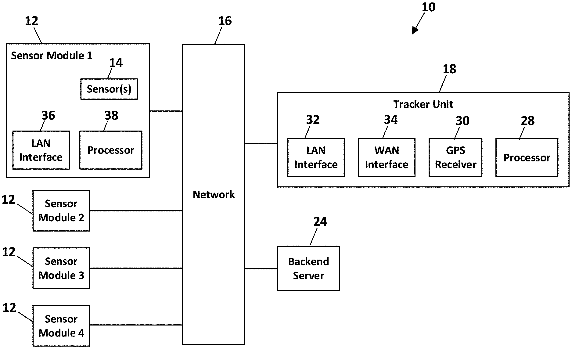
FIG. 1 depicts a cargo sensing system according to an embodiment of the invention;
FIG. 2 depicts a typical cargo trailer attached to a tractor;
FIG. 3A depicts a side elevation view of the interior of a cargo trailer with cargo sensing modules installed therein according to a preferred embodiment;
FIG. 3B depicts a top plan view of a cargo trailer with cargo sensing modules installed therein according to a preferred embodiment;
FIG. 3C depicts an end elevation view of a cargo trailer with cargo sensing modules installed therein according to a preferred embodiment;
FIGS. 4A and 4B depict a sensor module according to a preferred embodiment;
FIGS. 5A and 5B depict cargo detection areas according to a preferred embodiment;
FIG. 6 depicts a top plan view of a cargo trailer with cargo detection areas according to a preferred embodiment;
FIG. 7A depicts a side elevation view of a cargo trailer with the trailer door closed and with cargo sensing modules installed therein according to a preferred embodiment;
FIG. 7B depicts a side elevation view of a cargo trailer with the trailer door open and with cargo sensing modules installed therein according to a preferred embodiment;
FIG. 8 depicts a sensor module according to an alternative embodiment;
FIG. 9 depicts a top plan view of a cargo trailer with cargo detection areas according to an alternative embodiment;
FIG. 10A depicts a side elevation view of the interior of a cargo trailer with cargo sensing modules installed therein according to an alternative embodiment;
FIG. 10B depicts a top plan view of a cargo trailer with cargo sensing modules installed therein according to an alternative embodiment; and
FIG. 10C depicts an end elevation view of a cargo trailer with cargo sensing modules installed therein according to an alternative embodiment.
DETAILED DESCRIPTION
FIG. 1 depicts an embodiment of a cargo sensing system 10. Generally, the system 10 includes one or more sensor modules 12 distributed throughout a cargo container, such as the trailer 20 depicted in FIG. 2. Each sensor module 12 includes one or more distance sensors 14, which in a preferred embodiment are laser-ranging time-of-flight (ToF) sensors, such as the ST Micro VL53L1X manufactured by ST Microelectronics. In other embodiments, the distance sensor may implement other technology to determine the distance between the sensor and an impeding object. In some embodiments, the sensors 14 are ultrasonic sensors. In a preferred embodiment, each sensor module 12 includes a processor 38 for processing information from the distance sensor(s) 14, and local area network communication electronics 36 for communicating with other system components as described hereinafter. The local network communications electronics 36 may comprise one or more interfaces to implement wired communications protocols, such as Inter-integrated Circuit (I2C), Serial Peripheral Interface (SPI), Universal Asynchronous Receiver/Transmitter (UART), or Ethernet, or to implement wireless communications protocols, such as Wi-Fi, Bluetooth, or Bluetooth Low Energy.
Data generated by the sensor modules 12 are provided to a trailer tracker unit 18 and/or a backend server 24 for processing as described hereinafter. The tracker unit 18 monitors the location and health of the trailer 20, and sends the current cargo loading state of the trailer to the backend server 24 based on cargo detected using the sensor modules 12. The tracker unit 18, which is typically located in or on the trailer 20, preferably includes a processor 28, GPS receiver electronics 30 for determining location coordinates of the trailer 20, local area network communication electronics 32 for communicating with the sensor modules 12, and wide area network communication electronics 34 (such as a wireless cellular data modem) for communicating with the backend server 24. The local network communications electronics 30 may comprise one or more interfaces to implement wired communications protocols, such as I2C, SPI, UART, or Ethernet, or to implement wireless communications protocols, such as Wi-Fi, Bluetooth, or Bluetooth Low Energy. The tracker unit 18 may also interface with multiple external sensors, such as door sensors and temperature sensors.
The sensor modules 12 preferably communicate with the tracker unit 18 and/or the backend server 24 through a network 16, which may comprise a local area network in the trailer 20, a wireless data communication network, the Internet, or a combination of such networks. The sensor modules 12 may also communicate with the tracker unit 18 directly through serial or parallel interfaces. Each sensor module 12 preferably includes a local processor that communicates with processors of other sensor modules 12 through the network 16 or through a series of serial ports.
The preferred ToF sensor 14 has an angular field of view of about 25 degrees. A single one of these sensors mounted on the ceiling of the trailer 20 and pointing directly downward has a field of view that covers about half of the width of the floor area of the trailer. In a preferred embodiment depicted in FIGS. 4A and 4B, each sensor module 12 incorporates a faceted structure having four or more sensors 14 with their lines-of-sight angularly offset from each other by about 12 degrees in four or more different directions. As depicted in FIG. 5A, this multi-sensor module 12 provides a sensor pattern comprising four or more detection areas 22 that cover the trailer floor from wall-to-wall. This pattern allows each sensor module 12 to provide an accurate reading of the cumulative height of cargo containers in the module's detection areas. A fifth sensor 14 may be added pointing directly down to cover the open spot in the middle (see FIG. 5B). In one embodiment, a sensor module positioned closest to the trailer rear door may have an additional sensor pointing toward the door, thereby allowing that particular module to detect whether the door is open or closed, either by sensing ambient light, sensing the distance to the door, or a combination of both.
In an embodiment depicted in FIGS. 3A-3C, 4A, 4B, and 6, six sensor modules 12 are distributed along the length of the ceiling of the trailer 20, each including four sensors 14, thereby covering substantially the entire floor of the trailer 20 with twenty-four sensors. In some embodiments that do not require this level of accuracy, the floor of the trailer may be more sparsely sampled and still provide acceptable results.
Although a preferred embodiment disperses sensors evenly across the length of the trailer 20, other embodiments include more sensors in areas of the trailer 20 that are more likely to contain cargo (such as in the front and the back) and fewer sensors in the broad middle area of the trailer 20. For example, as depicted in FIG. 9, one embodiment includes sensor modules near the front and rear sections of the trailer that provide four detection areas, and sensor modules in the center that provide three detection areas.
In many trailers, the rear door is a roll-up door. In such a situation, the raised door may block one or more sensor modules mounted on the ceiling nearest the rear end of the trailer, such as the sensor modules 12a as shown in FIGS. 7A and 7B. In an embodiment designed to address this situation, a sensor module 12c may be mounted near the bottom of the door 26 and a sensor module 12b may be mounted near the top of the door 26. The sensor module 12c preferably includes a sensor that points down toward the floor when the door is closed. This sensor module 12c may be used to determine whether the door is closed or open, and to determine how far the door is open based on the distance from the sensor module 12c to the floor. When the door 26 is in a fully open position (FIG. 7B), the sensor modules 12b and 12c mounted near the top and bottom of the door face vertically down toward the floor. In this door-open position, the sensor modules 12b and 12c may be used for cargo detection, just as the sensor modules 12a that are blocked by the open door 26 were used.
In some embodiments, each sensor module 12 includes one or more accelerometers that can be used to determine the orientation of the sensors 14--whether they are facing horizontally or vertically--by sensing the direction of the acceleration of gravity relative to the position of the sensor module 12. Using this orientation information, the trailer tracker unit 18 or back-end server system 24 can determine how to treat the information provided by each sensor module 12.
In an embodiment depicted in FIG. 8, a sensor module 12 includes multiple sensors 14 distributed along the length of an elongate housing. This embodiment of the sensor module 12 may be approximately four feet long, with sensors 14 on each extreme end and one or more in the middle. Interface electronics within the module 12 provide for communications between the individual sensors 14, and communications with the tracker unit 18.
As shown in FIG. 3A, each sensor module 12 detects a distance between the sensor module 12 and the closest surfaces that are within the module's detection zone. The detected surfaces may be the floor of the trailer or surfaces of pieces of cargo. For example, one sensor within the sensor module designated as Module 2 detects a distance d1 to the floor of the trailer, and another sensor within Module 2 detects a distance d2 to the top surface of a cargo container. One sensor within the sensor module designated as Module 3 detects a distance d3 to the top surface of a cargo container, and another sensor within Module 3 detects a distance d4 to the floor.
In a preferred embodiment, distance measurements from each detection zone, and/or the areas 22 within each detection zone, are reported either to the tracker unit 18 or via the tracker unit 18 to the back-end server 24. Using the distance measurements, a process executed by the back-end server 24 or by a processor in the tracker unit 18 determines one or more of: (1) the total floor area of the trailer 20 that is occupied by cargo; (2) the total volume of the trailer 20 that is occupied; (3) which detection areas of the trailer floor are occupied; and (4) the height to which each detection area of the trailer is loaded.
The occupied floor area (1) may be determined by counting the number of detection areas that report a distance (d1, d2, d3, d4, etc.) that is less than some threshold value related to the full height of the interior of the trailer, and multiplying that number by the floor area within each detection area. For example, if the threshold value is 110 inches, a reported distance of less than 110 inches indicates that the corresponding detection area 22 is occupied by cargo. In the exemplary trailer 20 depicted in FIG. 6, there are twenty-four detection areas 22, each occupying about 13 square feet of floor area. If sensors in twenty of the detection areas 22 report distances that are less than the threshold value, then at least about 260 ft.sup.2 of the trailer floor space is occupied by cargo. (20.times.13 ft.sup.2=260 ft.sup.2)
The occupied trailer volume (2) may be determined by multiplying the size of each occupied detection area by the height above the floor of the detected cargo surface, and adding them all up. For example, if the twenty occupied areas from the previous example all have detected cargo surfaces that are at least 90 inches above the floor, then at least about 1950 ft.sup.3 of the trailer volume is occupied. (20.times.13 ft.sup.2.times.90/12 ft=1950 ft.sup.3)
Other information may be inferred as well, such as weight based on knowledge of the type of cargo and its total volume, and other relevant information. This information can be used in concert with an imaging cargo sensor to provide images at relevant times based on the position and state of the cargo load. The back end server 24 may also use this data to build a three-dimensional visualization of the cargo in the trailer, such as by displaying blocks based on x-position and y-position along with height in the z-direction.
In preferred embodiments, the sensor modules 12 are located near the center of the ceiling of the trailer. In an alternative embodiment depicted in FIGS. 10A-10C, sensor modules 12 may also be mounted in the corners of the trailer ceiling looking toward the opposite corners. This could provide a view with a larger detection areas 22 using fewer sensors.
The foregoing description of preferred embodiments for this invention have been presented for purposes of illustration and description. They are not intended to be exhaustive or to limit the invention to the precise form disclosed. Obvious modifications or variations are possible in light of the above teachings. The embodiments are chosen and described in an effort to provide the best illustrations of the principles of the invention and its practical application, and to thereby enable one of ordinary skill in the art to utilize the invention in various embodiments and with various modifications as are suited to the particular use contemplated. All such modifications and variations are within the scope of the invention as determined by the appended claims when interpreted in accordance with the breadth to which they are fairly, legally, and equitably entitled.
* * * * *
D00000
D00001
D00002
D00003
D00004
D00005
D00006
XML
uspto.report is an independent third-party trademark research tool that is not affiliated, endorsed, or sponsored by the United States Patent and Trademark Office (USPTO) or any other governmental organization. The information provided by uspto.report is based on publicly available data at the time of writing and is intended for informational purposes only.
While we strive to provide accurate and up-to-date information, we do not guarantee the accuracy, completeness, reliability, or suitability of the information displayed on this site. The use of this site is at your own risk. Any reliance you place on such information is therefore strictly at your own risk.
All official trademark data, including owner information, should be verified by visiting the official USPTO website at www.uspto.gov. This site is not intended to replace professional legal advice and should not be used as a substitute for consulting with a legal professional who is knowledgeable about trademark law.