Surgical robotic automation with tracking markers and controlled tool advancement
Crawford , et al. April 12, 2
U.S. patent number 11,298,196 [Application Number 15/881,971] was granted by the patent office on 2022-04-12 for surgical robotic automation with tracking markers and controlled tool advancement. This patent grant is currently assigned to Globus Medical Inc.. The grantee listed for this patent is GLOBUS MEDICAL, INC.. Invention is credited to Neil R. Crawford, Norbert Johnson, Nicholas Theodore.


View All Diagrams
| United States Patent | 11,298,196 |
| Crawford , et al. | April 12, 2022 |
Surgical robotic automation with tracking markers and controlled tool advancement
Abstract
Devices, systems, and methods for aiding insertion of a surgical implant by providing a threaded guide tube configured to engage a threaded surgical instrument such that an end-effector of a robot may provide force to drive the surgical implant into a patient. In addition, devices, systems, and methods relating to a dilator system for use with a robotic system that allows independent and separate control of tools within the dilator system.
| Inventors: | Crawford; Neil R. (Chandler, AZ), Johnson; Norbert (North Andover, MA), Theodore; Nicholas (Paradise Valley, AZ) | ||||||||||
|---|---|---|---|---|---|---|---|---|---|---|---|
| Applicant: |
|
||||||||||
| Assignee: | Globus Medical Inc. (Audubon,
PA) |
||||||||||
| Family ID: | 81000574 | ||||||||||
| Appl. No.: | 15/881,971 | ||||||||||
| Filed: | January 29, 2018 |
Prior Publication Data
| Document Identifier | Publication Date | |
|---|---|---|
| US 20180147018 A1 | May 31, 2018 | |
Related U.S. Patent Documents
| Application Number | Filing Date | Patent Number | Issue Date | ||
|---|---|---|---|---|---|
| 15609334 | May 31, 2017 | ||||
| 15157444 | May 18, 2016 | ||||
| 15095883 | Apr 11, 2016 | 10893912 | |||
| 14062707 | Oct 24, 2013 | 10357184 | |||
| 13924505 | Oct 10, 2017 | 9782229 | |||
| 61800527 | Mar 15, 2013 | ||||
| 61662702 | Jun 21, 2012 | ||||
| Current U.S. Class: | 1/1 |
| Current CPC Class: | A61F 2/4611 (20130101); A61B 17/02 (20130101); A61B 34/30 (20160201); A61B 17/7035 (20130101); A61B 17/7082 (20130101); A61B 34/20 (20160201); A61F 2/4455 (20130101); A61B 90/11 (20160201); A61F 2/447 (20130101); A61B 34/32 (20160201); A61F 2/4465 (20130101); A61B 17/7083 (20130101); A61B 2090/3937 (20160201); A61B 34/76 (20160201); A61M 25/0662 (20130101); A61F 2002/4629 (20130101); A61B 17/1757 (20130101); A61B 2017/0042 (20130101); A61F 2002/4628 (20130101); A61B 2017/00477 (20130101); A61B 2090/3983 (20160201); A61B 2034/2072 (20160201); A61B 2090/3945 (20160201); A61F 2002/30133 (20130101); A61B 2090/365 (20160201); A61B 2090/3966 (20160201); A61M 29/00 (20130101); A61B 2090/3979 (20160201); A61B 2017/00876 (20130101); A61B 2034/2055 (20160201); A61B 2090/376 (20160201); A61B 2090/3762 (20160201); A61B 2034/2065 (20160201) |
| Current International Class: | A61B 17/70 (20060101); A61B 90/11 (20160101); A61B 34/20 (20160101); A61B 34/30 (20160101); A61B 17/02 (20060101); A61B 90/00 (20160101); A61B 17/17 (20060101); A61B 17/00 (20060101); A61M 29/00 (20060101) |
References Cited [Referenced By]
U.S. Patent Documents
| 4150293 | April 1979 | Franke |
| 5020933 | June 1991 | Salvestro et al. |
| 5246010 | September 1993 | Gazzara et al. |
| 5354314 | October 1994 | Hardy et al. |
| 5397323 | March 1995 | Taylor et al. |
| 5598453 | January 1997 | Baba et al. |
| 5772594 | June 1998 | Barrick |
| 5791908 | August 1998 | Gillio |
| 5820559 | October 1998 | Ng et al. |
| 5825982 | October 1998 | Wright et al. |
| 5887121 | March 1999 | Funda et al. |
| 5911449 | June 1999 | Daniele et al. |
| 5951475 | September 1999 | Gueziec et al. |
| 5987960 | November 1999 | Messner et al. |
| 6012216 | January 2000 | Esteves et al. |
| 6031888 | February 2000 | Ivan et al. |
| 6033415 | March 2000 | Mittelstadt et al. |
| 6080181 | June 2000 | Jensen et al. |
| 6106511 | August 2000 | Jensen |
| 6122541 | September 2000 | Cosman et al. |
| 6144875 | November 2000 | Schweikard et al. |
| 6157853 | December 2000 | Blume et al. |
| 6167145 | December 2000 | Foley et al. |
| 6167292 | December 2000 | Badano et al. |
| 6201984 | March 2001 | Funda et al. |
| 6203196 | March 2001 | Meyer et al. |
| 6205411 | March 2001 | DiGioia, III et al. |
| 6212419 | April 2001 | Blume et al. |
| 6231565 | May 2001 | Tovey et al. |
| 6236875 | May 2001 | Bucholz et al. |
| 6246900 | June 2001 | Cosman et al. |
| 6301495 | October 2001 | Gueziec et al. |
| 6306126 | October 2001 | Montezuma |
| 6312435 | November 2001 | Wallace et al. |
| 6314311 | November 2001 | Williams et al. |
| 6320929 | November 2001 | Von Der Haar |
| 6322567 | November 2001 | Mittelstadt et al. |
| 6325808 | December 2001 | Bernard et al. |
| 6340363 | January 2002 | Bolger et al. |
| 6377011 | April 2002 | Ben-Ur |
| 6379302 | April 2002 | Kessman et al. |
| 6402762 | June 2002 | Hunter et al. |
| 6424885 | July 2002 | Niemeyer et al. |
| 6447503 | September 2002 | Wynne et al. |
| 6451027 | September 2002 | Cooper et al. |
| 6477400 | November 2002 | Barrick |
| 6484049 | November 2002 | Seeley et al. |
| 6487267 | November 2002 | Wolter |
| 6490467 | December 2002 | Bucholz et al. |
| 6490475 | December 2002 | Seeley et al. |
| 6499488 | December 2002 | Hunter et al. |
| 6501981 | December 2002 | Schweikard et al. |
| 6507751 | January 2003 | Blume et al. |
| 6535756 | March 2003 | Simon et al. |
| 6560354 | May 2003 | Maurer, Jr. et al. |
| 6565554 | May 2003 | Niemeyer |
| 6587750 | July 2003 | Gerbi et al. |
| 6614453 | September 2003 | Suri et al. |
| 6614871 | September 2003 | Kobiki et al. |
| 6619840 | September 2003 | Rasche et al. |
| 6636757 | October 2003 | Jascob et al. |
| 6645196 | November 2003 | Nixon et al. |
| 6666579 | December 2003 | Jensen |
| 6669635 | December 2003 | Kessman et al. |
| 6701173 | March 2004 | Nowinski et al. |
| 6757068 | June 2004 | Foxlin |
| 6782287 | August 2004 | Grzeszczuk et al. |
| 6783524 | August 2004 | Anderson et al. |
| 6786896 | September 2004 | Madhani et al. |
| 6788018 | September 2004 | Blumenkranz |
| 6804581 | October 2004 | Wang et al. |
| 6823207 | November 2004 | Jensen et al. |
| 6827351 | December 2004 | Graziani et al. |
| 6837892 | January 2005 | Shoham |
| 6839612 | January 2005 | Sanchez et al. |
| 6856826 | February 2005 | Seeley et al. |
| 6856827 | February 2005 | Seeley et al. |
| 6879880 | April 2005 | Nowlin et al. |
| 6892090 | May 2005 | Verard et al. |
| 6920347 | July 2005 | Simon et al. |
| 6922632 | July 2005 | Foxlin |
| 6968224 | November 2005 | Kessman et al. |
| 6978166 | December 2005 | Foley et al. |
| 6988009 | January 2006 | Grimm et al. |
| 6991627 | January 2006 | Madhani et al. |
| 6996487 | February 2006 | Jutras et al. |
| 6999852 | February 2006 | Green |
| 7007699 | March 2006 | Martinelli et al. |
| 7016457 | March 2006 | Senzig et al. |
| 7043961 | May 2006 | Pandey et al. |
| 7062006 | June 2006 | Pelc et al. |
| 7063705 | June 2006 | Young et al. |
| 7072707 | July 2006 | Galloway, Jr. et al. |
| 7083615 | August 2006 | Peterson et al. |
| 7097640 | August 2006 | Wang et al. |
| 7099428 | August 2006 | Clinthorne et al. |
| 7108421 | September 2006 | Gregerson et al. |
| 7130676 | October 2006 | Barrick |
| 7139418 | November 2006 | Abovitz et al. |
| 7139601 | November 2006 | Bucholz et al. |
| 7155316 | December 2006 | Sutherland et al. |
| 7164968 | January 2007 | Treat et al. |
| 7167738 | January 2007 | Schweikard et al. |
| 7169141 | January 2007 | Brock et al. |
| 7172627 | February 2007 | Fiere et al. |
| 7194120 | March 2007 | Wicker et al. |
| 7197107 | March 2007 | Arai et al. |
| 7207995 | April 2007 | Vandewalle |
| 7231014 | June 2007 | Levy |
| 7231063 | June 2007 | Naimark et al. |
| 7239940 | July 2007 | Wang et al. |
| 7248914 | July 2007 | Hastings et al. |
| 7301648 | November 2007 | Foxlin |
| 7302288 | November 2007 | Schellenberg |
| 7313430 | December 2007 | Urquhart et al. |
| 7318805 | January 2008 | Schweikard et al. |
| 7318827 | January 2008 | Leitner et al. |
| 7319897 | January 2008 | Leitner et al. |
| 7324623 | January 2008 | Heuscher et al. |
| 7327865 | February 2008 | Fu et al. |
| 7331967 | February 2008 | Lee et al. |
| 7333642 | February 2008 | Green |
| 7339341 | March 2008 | Oleynikov et al. |
| 7366562 | April 2008 | Dukesherer et al. |
| 7379790 | May 2008 | Toth et al. |
| 7386365 | June 2008 | Nixon |
| 7422592 | September 2008 | Morley et al. |
| 7435216 | October 2008 | Kwon et al. |
| 7440793 | October 2008 | Chauhan et al. |
| 7460637 | December 2008 | Clinthorne et al. |
| 7466303 | December 2008 | Yi et al. |
| 7493153 | February 2009 | Ahmed et al. |
| 7505617 | March 2009 | Fu et al. |
| 7533892 | May 2009 | Schena et al. |
| 7542791 | June 2009 | Mire et al. |
| 7555331 | June 2009 | Viswanathan |
| 7567834 | July 2009 | Clayton et al. |
| 7594912 | September 2009 | Cooper et al. |
| 7606613 | October 2009 | Simon et al. |
| 7607440 | October 2009 | Coste-Maniere et al. |
| 7623902 | November 2009 | Pacheco |
| 7630752 | December 2009 | Viswanathan |
| 7630753 | December 2009 | Simon et al. |
| 7643862 | January 2010 | Schoenefeld |
| 7660623 | February 2010 | Hunter et al. |
| 7661881 | February 2010 | Gregerson et al. |
| 7683331 | March 2010 | Chang |
| 7683332 | March 2010 | Chang |
| 7689320 | March 2010 | Prisco et al. |
| 7691098 | April 2010 | Wallace et al. |
| 7702379 | April 2010 | Winash et al. |
| 7702477 | April 2010 | Tuemmler et al. |
| 7711083 | May 2010 | Heigl et al. |
| 7711406 | May 2010 | Kuhn et al. |
| 7720523 | May 2010 | Omemick et al. |
| 7725253 | May 2010 | Foxlin |
| 7726171 | June 2010 | Langlotz et al. |
| 7742801 | June 2010 | Neubauer et al. |
| 7751865 | July 2010 | Jascob et al. |
| 7760849 | July 2010 | Zhang |
| 7762825 | July 2010 | Burbank et al. |
| 7763015 | July 2010 | Cooper et al. |
| 7787699 | August 2010 | Mahesh et al. |
| 7796728 | September 2010 | Bergfjord |
| 7813838 | October 2010 | Sommer |
| 7818044 | October 2010 | Dukesherer et al. |
| 7819859 | October 2010 | Prisco et al. |
| 7824401 | November 2010 | Manzo et al. |
| 7831294 | November 2010 | Viswanathan |
| 7834484 | November 2010 | Sartor |
| 7835557 | November 2010 | Kendrick et al. |
| 7835778 | November 2010 | Foley et al. |
| 7835784 | November 2010 | Mire et al. |
| 7840253 | November 2010 | Tremblay et al. |
| 7840256 | November 2010 | Lakin et al. |
| 7843158 | November 2010 | Prisco |
| 7844320 | November 2010 | Shahidi |
| 7853305 | December 2010 | Simon et al. |
| 7853313 | December 2010 | Thompson |
| 7865269 | January 2011 | Prisco et al. |
| D631966 | February 2011 | Perloff et al. |
| 7879045 | February 2011 | Gielen et al. |
| 7881767 | February 2011 | Strommer et al. |
| 7881770 | February 2011 | Melkent et al. |
| 7886743 | February 2011 | Cooper et al. |
| RE42194 | March 2011 | Foley et al. |
| RE42226 | March 2011 | Foley et al. |
| 7900524 | March 2011 | Calloway et al. |
| 7907166 | March 2011 | Lamprecht et al. |
| 7909122 | March 2011 | Schena et al. |
| 7925653 | April 2011 | Saptharishi |
| 7930065 | April 2011 | Larkin et al. |
| 7935130 | May 2011 | Willliams |
| 7940999 | May 2011 | Liao et al. |
| 7945012 | May 2011 | Ye et al. |
| 7945021 | May 2011 | Shapiro et al. |
| 7953470 | May 2011 | Vetter et al. |
| 7954397 | June 2011 | Choi et al. |
| 7971341 | July 2011 | Dukesherer et al. |
| 7974674 | July 2011 | Hauck et al. |
| 7974677 | July 2011 | Mire et al. |
| 7974681 | July 2011 | Wallace et al. |
| 7979157 | July 2011 | Anvari |
| 7983733 | July 2011 | Viswanathan |
| 7988215 | August 2011 | Seibold |
| 7996110 | August 2011 | Lipow et al. |
| 8004121 | August 2011 | Sartor |
| 8004229 | August 2011 | Nowlin et al. |
| 8010177 | August 2011 | Csavoy et al. |
| 8019045 | September 2011 | Kato |
| 8021310 | September 2011 | Sanborn et al. |
| 8035685 | October 2011 | Jensen |
| 8046054 | October 2011 | Kim et al. |
| 8046057 | October 2011 | Clarke |
| 8052688 | November 2011 | Wolf, II |
| 8054184 | November 2011 | Cline et al. |
| 8054752 | November 2011 | Druke et al. |
| 8057397 | November 2011 | Li et al. |
| 8057407 | November 2011 | Martinelli et al. |
| 8062288 | November 2011 | Cooper et al. |
| 8062375 | November 2011 | Glerum et al. |
| 8066524 | November 2011 | Burbank et al. |
| 8073335 | December 2011 | Labonville et al. |
| 8079950 | December 2011 | Stern et al. |
| 8086299 | December 2011 | Adler et al. |
| 8092370 | January 2012 | Roberts et al. |
| 8098914 | January 2012 | Liao et al. |
| 8100950 | January 2012 | St. Clair et al. |
| 8105320 | January 2012 | Manzo |
| 8108025 | January 2012 | Csavoy et al. |
| 8109877 | February 2012 | Moctezuma de la Barrera et al. |
| 8112292 | February 2012 | Simon |
| 8116430 | February 2012 | Shapiro et al. |
| 8120301 | February 2012 | Goldberg et al. |
| 8121249 | February 2012 | Wang et al. |
| 8123675 | February 2012 | Funda et al. |
| 8133229 | March 2012 | Bonutti |
| 8142420 | March 2012 | Schena |
| 8147494 | April 2012 | Leitner et al. |
| 8150494 | April 2012 | Simon et al. |
| 8150497 | April 2012 | Gielen et al. |
| 8150498 | April 2012 | Gielen et al. |
| 8165658 | April 2012 | Waynik et al. |
| 8170313 | May 2012 | Kendrick et al. |
| 8179073 | May 2012 | Farritor et al. |
| 8182476 | May 2012 | Julian et al. |
| 8184880 | May 2012 | Zhao et al. |
| 8202278 | June 2012 | Orban, III et al. |
| 8208708 | June 2012 | Homan et al. |
| 8208988 | June 2012 | Jensen |
| 8219177 | July 2012 | Smith et al. |
| 8219178 | July 2012 | Smith et al. |
| 8220468 | July 2012 | Cooper et al. |
| 8224024 | July 2012 | Foxlin et al. |
| 8224484 | July 2012 | Swarup et al. |
| 8225798 | July 2012 | Baldwin et al. |
| 8228368 | July 2012 | Zhao et al. |
| 8231610 | July 2012 | Jo et al. |
| 8263933 | July 2012 | Hartmann et al. |
| 8239001 | August 2012 | Verard et al. |
| 8241271 | August 2012 | Millman et al. |
| 8248413 | August 2012 | Gattani et al. |
| 8256319 | September 2012 | Cooper et al. |
| 8271069 | September 2012 | Jascob et al. |
| 8271130 | September 2012 | Hourtash |
| 8281670 | October 2012 | Larkin et al. |
| 8282653 | October 2012 | Nelson et al. |
| 8301226 | October 2012 | Csavoy et al. |
| 8311611 | November 2012 | Csavoy et al. |
| 8313430 | November 2012 | Pimenta |
| 8320991 | November 2012 | Jascob et al. |
| 8332012 | December 2012 | Kienzle, III |
| 8333755 | December 2012 | Cooper et al. |
| 8335552 | December 2012 | Stiles |
| 8335557 | December 2012 | Maschke |
| 8348931 | January 2013 | Cooper et al. |
| 8353963 | January 2013 | Glerum |
| 8358818 | January 2013 | Miga et al. |
| 8359730 | January 2013 | Burg et al. |
| 8374673 | February 2013 | Adcox et al. |
| 8374723 | February 2013 | Zhao et al. |
| 8379791 | February 2013 | Forthmann et al. |
| 8386019 | February 2013 | Camus et al. |
| 8392022 | March 2013 | Ortmaier et al. |
| 8394099 | March 2013 | Patwardhan |
| 8395342 | March 2013 | Prisco |
| 8398634 | March 2013 | Manzo et al. |
| 8400094 | March 2013 | Schena |
| 8414957 | April 2013 | Enzerink et al. |
| 8418073 | April 2013 | Mohr et al. |
| 8450694 | May 2013 | Baviera et al. |
| 8452447 | May 2013 | Nixon |
| RE44305 | June 2013 | Foley et al. |
| 8462911 | June 2013 | Vesel et al. |
| 8465476 | June 2013 | Rogers et al. |
| 8465771 | June 2013 | Wan et al. |
| 8467851 | June 2013 | Mire et al. |
| 8467852 | June 2013 | Csavoy et al. |
| 8469947 | June 2013 | Devengenzo et al. |
| RE44392 | July 2013 | Hynes |
| 8483434 | July 2013 | Buehner et al. |
| 8483800 | July 2013 | Jensen et al. |
| 8486532 | July 2013 | Enzerink et al. |
| 8489235 | July 2013 | Moll et al. |
| 8500722 | August 2013 | Cooper |
| 8500728 | August 2013 | Newton et al. |
| 8504201 | August 2013 | Moll et al. |
| 8506555 | August 2013 | Ruiz Morales |
| 8506556 | August 2013 | Schena |
| 8508173 | August 2013 | Goldberg et al. |
| 8512318 | August 2013 | Tovey et al. |
| 8515576 | August 2013 | Lipow et al. |
| 8518120 | August 2013 | Glerum et al. |
| 8521331 | August 2013 | Itkowitz |
| 8526688 | September 2013 | Groszmann et al. |
| 8526700 | September 2013 | Isaacs |
| 8527094 | September 2013 | Kumar et al. |
| 8528440 | September 2013 | Morley et al. |
| 8532741 | September 2013 | Heruth et al. |
| 8541970 | September 2013 | Nowlin et al. |
| 8548563 | October 2013 | Simon et al. |
| 8549732 | October 2013 | Burg et al. |
| 8551114 | October 2013 | Ramos de la Pena |
| 8551116 | October 2013 | Julian et al. |
| 8556807 | October 2013 | Scott et al. |
| 8556979 | October 2013 | Glerum et al. |
| 8560118 | October 2013 | Green et al. |
| 8561473 | October 2013 | Blumenkranz |
| 8562594 | October 2013 | Cooper et al. |
| 8571638 | October 2013 | Shoham |
| 8571710 | October 2013 | Coste-Maniere et al. |
| 8573465 | November 2013 | Shelton, IV |
| 8574303 | November 2013 | Sharkey et al. |
| 8585420 | November 2013 | Burbank et al. |
| 8594841 | November 2013 | Zhao et al. |
| 8597198 | December 2013 | Sanborn et al. |
| 8600478 | December 2013 | Verard et al. |
| 8603077 | December 2013 | Cooper et al. |
| 8611985 | December 2013 | Lavallee et al. |
| 8613230 | December 2013 | Blumenkranz et al. |
| 8621939 | January 2014 | Blumenkranz et al. |
| 8624537 | January 2014 | Nowlin et al. |
| 8630389 | January 2014 | Kato |
| 8634897 | January 2014 | Simon et al. |
| 8634957 | January 2014 | Toth et al. |
| 8638056 | January 2014 | Goldberg et al. |
| 8638057 | January 2014 | Goldberg et al. |
| 8639000 | January 2014 | Zhao et al. |
| 8641726 | February 2014 | Bonutti |
| 8644907 | February 2014 | Hartmann et al. |
| 8657809 | February 2014 | Schoepp |
| 8660635 | February 2014 | Simon et al. |
| 8666544 | March 2014 | Moll et al. |
| 8675939 | March 2014 | Moctezuma de la Barrera |
| 8678647 | March 2014 | Gregerson et al. |
| 8679125 | March 2014 | Smith et al. |
| 8679183 | March 2014 | Glerum et al. |
| 8682413 | March 2014 | Lloyd |
| 8684253 | April 2014 | Giordano et al. |
| 8685098 | April 2014 | Glerum et al. |
| 8693730 | April 2014 | Umasuthan et al. |
| 8694075 | April 2014 | Groszmann et al. |
| 8696458 | April 2014 | Foxlin et al. |
| 8700123 | April 2014 | Okamura et al. |
| 8706086 | April 2014 | Glerum |
| 8706185 | April 2014 | Foley et al. |
| 8706301 | April 2014 | Zhao et al. |
| 8717430 | May 2014 | Simon et al. |
| 8727618 | May 2014 | Maschke et al. |
| 8734432 | May 2014 | Tuma et al. |
| 8738115 | May 2014 | Amberg et al. |
| 8738181 | May 2014 | Greer et al. |
| 8740882 | June 2014 | Jun et al. |
| 8746252 | June 2014 | McGrogan et al. |
| 8749189 | June 2014 | Nowlin et al. |
| 8749190 | June 2014 | Nowlin et al. |
| 8761930 | June 2014 | Nixon |
| 8764448 | July 2014 | Yang et al. |
| 8771170 | July 2014 | Mesallum et al. |
| 8781186 | July 2014 | Clements et al. |
| 8781630 | July 2014 | Banks et al. |
| 8784385 | July 2014 | Boyden et al. |
| 8786241 | July 2014 | Nowlin et al. |
| 8787520 | July 2014 | Baba |
| 8792704 | July 2014 | Isaacs |
| 8798231 | August 2014 | Notohara et al. |
| 8800838 | August 2014 | Shelton, IV |
| 8808164 | August 2014 | Hoffman et al. |
| 8812077 | August 2014 | Dempsey |
| 8814793 | August 2014 | Brabrand |
| 8816628 | August 2014 | Nowlin et al. |
| 8818105 | August 2014 | Myronenko et al. |
| 8820605 | September 2014 | Shelton, IV |
| 8821511 | September 2014 | Von Jako et al. |
| 8823308 | September 2014 | Nowlin et al. |
| 8827996 | September 2014 | Scott et al. |
| 8828024 | September 2014 | Farritor et al. |
| 8830224 | September 2014 | Zhao et al. |
| 8834489 | September 2014 | Cooper et al. |
| 8834490 | September 2014 | Bonutti |
| 8838270 | September 2014 | Druke et al. |
| 8844789 | September 2014 | Shelton, IV et al. |
| 8855822 | October 2014 | Bartol et al. |
| 8858598 | October 2014 | Seifert et al. |
| 8860753 | October 2014 | Bhandarkar et al. |
| 8864751 | October 2014 | Prisco et al. |
| 8864798 | October 2014 | Weiman et al. |
| 8864833 | October 2014 | Glerum et al. |
| 8867703 | October 2014 | Shapiro et al. |
| 8870880 | October 2014 | Himmelberger et al. |
| 8876866 | November 2014 | Zappacosta et al. |
| 8880223 | November 2014 | Raj et al. |
| 8882803 | November 2014 | Iott et al. |
| 8883210 | November 2014 | Truncale et al. |
| 8888821 | November 2014 | Rezach et al. |
| 8888853 | November 2014 | Glerum et al. |
| 8888854 | November 2014 | Glerum et al. |
| 8894652 | November 2014 | Seifert et al. |
| 8894688 | November 2014 | Suh |
| 8894691 | November 2014 | Iott et al. |
| 8906069 | December 2014 | Hansell et al. |
| 8964934 | February 2015 | Ein-Gal |
| 8992580 | March 2015 | Bar et al. |
| 8996169 | March 2015 | Lightcap et al. |
| 9001963 | April 2015 | Sowards-Emmerd et al. |
| 9002076 | April 2015 | Khadem et al. |
| 9044190 | June 2015 | Rubner et al. |
| 9107683 | August 2015 | Hourtash et al. |
| 9125556 | September 2015 | Zehavi et al. |
| 9131986 | September 2015 | Greer et al. |
| 9215968 | December 2015 | Schostek et al. |
| 9308050 | April 2016 | Kostrzewski et al. |
| 9380984 | July 2016 | Li et al. |
| 9393039 | July 2016 | Lechner et al. |
| 9398886 | July 2016 | Gregerson et al. |
| 9398890 | July 2016 | Dong et al. |
| 9414859 | August 2016 | Ballard et al. |
| 9420975 | August 2016 | Gutfleisch et al. |
| 9463073 | October 2016 | Gill et al. |
| 9492235 | November 2016 | Hourtash et al. |
| 9592096 | March 2017 | Maillet et al. |
| 9750465 | September 2017 | Engel et al. |
| 9757203 | September 2017 | Hourtash et al. |
| 9795354 | October 2017 | Menegaz et al. |
| 9814535 | November 2017 | Bar et al. |
| 9820783 | November 2017 | Donner et al. |
| 9833265 | November 2017 | Donner et al. |
| 9848922 | December 2017 | Tohmeh et al. |
| 9925011 | March 2018 | Gombert et al. |
| 9931025 | April 2018 | Graetzel et al. |
| 10034717 | July 2018 | Miller et al. |
| 10575906 | March 2020 | Wu |
| 2001/0036302 | November 2001 | Miller |
| 2002/0035321 | March 2002 | Bucholz et al. |
| 2003/0161442 | August 2003 | Zeiss |
| 2004/0019263 | January 2004 | Jutras et al. |
| 2004/0024311 | February 2004 | Quaid |
| 2004/0034302 | February 2004 | Abovitz et al. |
| 2004/0068172 | April 2004 | Nowinski et al. |
| 2004/0076259 | April 2004 | Jensen et al. |
| 2004/0157188 | August 2004 | Luth et al. |
| 2005/0085714 | April 2005 | Foley et al. |
| 2005/0096502 | May 2005 | Khalili |
| 2005/0107679 | May 2005 | Geiger et al. |
| 2005/0119639 | June 2005 | McCombs et al. |
| 2005/0143651 | June 2005 | Verard et al. |
| 2005/0149045 | July 2005 | Elliott |
| 2005/0171558 | August 2005 | Abovitz et al. |
| 2005/0215888 | September 2005 | Grimm et al. |
| 2006/0036264 | February 2006 | Selover et al. |
| 2006/0100610 | May 2006 | Wallace et al. |
| 2006/0142657 | June 2006 | Quaid et al. |
| 2006/0173329 | August 2006 | Marquart et al. |
| 2006/0178559 | August 2006 | Kumar et al. |
| 2006/0184396 | August 2006 | Dennis et al. |
| 2006/0241416 | October 2006 | Marquart et al. |
| 2006/0264963 | November 2006 | Reed et al. |
| 2006/0291612 | December 2006 | Nishide et al. |
| 2007/0001879 | January 2007 | Kaftan et al. |
| 2007/0015987 | January 2007 | Benlloch Baviera et al. |
| 2007/0016009 | January 2007 | Lakin et al. |
| 2007/0021738 | January 2007 | Hasser et al. |
| 2007/0038059 | February 2007 | Sheffer et al. |
| 2007/0073133 | March 2007 | Schoenefeld |
| 2007/0122020 | May 2007 | Claus et al. |
| 2007/0156121 | July 2007 | Millman et al. |
| 2007/0156157 | July 2007 | Nahum et al. |
| 2007/0167712 | July 2007 | Keglovich et al. |
| 2007/0233238 | October 2007 | Huynh et al. |
| 2007/0238985 | October 2007 | Smith et al. |
| 2008/0004523 | January 2008 | Jensen |
| 2008/0010706 | January 2008 | Moses et al. |
| 2008/0013809 | January 2008 | Zhu et al. |
| 2008/0033283 | February 2008 | Dellaca et al. |
| 2008/0046122 | February 2008 | Manzo et al. |
| 2008/0082109 | April 2008 | Moll et al. |
| 2008/0108912 | May 2008 | Node-Langlois |
| 2008/0108991 | May 2008 | Von Jako |
| 2008/0109012 | May 2008 | Falco et al. |
| 2008/0119725 | May 2008 | Lloyd |
| 2008/0144906 | June 2008 | Allred et al. |
| 2008/0154389 | June 2008 | Smith et al. |
| 2008/0161680 | July 2008 | Von Jako et al. |
| 2008/0161682 | July 2008 | Kendrick et al. |
| 2008/0177203 | July 2008 | von Jako |
| 2008/0188934 | August 2008 | Moser et al. |
| 2008/0200794 | August 2008 | Teichman et al. |
| 2008/0214922 | September 2008 | Hartmann et al. |
| 2008/0228068 | September 2008 | Viswanathan et al. |
| 2008/0228195 | September 2008 | von Jako et al. |
| 2008/0228196 | September 2008 | Wang et al. |
| 2008/0235052 | September 2008 | Node-Langlois et al. |
| 2008/0269596 | October 2008 | Revie et al. |
| 2008/0287771 | November 2008 | Anderson |
| 2008/0287781 | November 2008 | Revie et al. |
| 2008/0300477 | December 2008 | Lloyd et al. |
| 2008/0300478 | December 2008 | Zuhars et al. |
| 2008/0302950 | December 2008 | Park et al. |
| 2008/0306490 | December 2008 | Lakin et al. |
| 2008/0319311 | December 2008 | Hamadeh |
| 2009/0012509 | January 2009 | Csavoy et al. |
| 2009/0030428 | January 2009 | Omori et al. |
| 2009/0080737 | March 2009 | Battle et al. |
| 2009/0099445 | April 2009 | Burger |
| 2009/0185655 | July 2009 | Koken et al. |
| 2009/0198121 | August 2009 | Hoheisel |
| 2009/0216113 | August 2009 | Meier et al. |
| 2009/0228019 | September 2009 | Gross et al. |
| 2009/0234217 | September 2009 | Mire et al. |
| 2009/0240141 | September 2009 | Neubauer et al. |
| 2009/0254326 | October 2009 | Isaacs |
| 2009/0259123 | October 2009 | Navab et al. |
| 2009/0259230 | October 2009 | Khadem et al. |
| 2009/0264899 | October 2009 | Appenrodt et al. |
| 2009/0281417 | November 2009 | Hartmann et al. |
| 2009/0306480 | December 2009 | Protopsaltis |
| 2009/0306499 | December 2009 | Van Vorhis et al. |
| 2010/0022874 | January 2010 | Wang et al. |
| 2010/0039506 | February 2010 | Sarvestani et al. |
| 2010/0046718 | February 2010 | Weiser et al. |
| 2010/0076305 | March 2010 | Maier-Hein et al. |
| 2010/0114288 | May 2010 | Haller et al. |
| 2010/0125286 | May 2010 | Wang et al. |
| 2010/0130986 | May 2010 | Mailloux et al. |
| 2010/0174410 | July 2010 | Greer et al. |
| 2010/0228117 | September 2010 | Hartmann |
| 2010/0228265 | September 2010 | Prisco |
| 2010/0228340 | September 2010 | Erbel et al. |
| 2010/0249571 | September 2010 | Jensen et al. |
| 2010/0274120 | October 2010 | Heuscher |
| 2010/0280363 | November 2010 | Skarda et al. |
| 2010/0331858 | December 2010 | Simaan et al. |
| 2011/0019884 | January 2011 | Blau |
| 2011/0020084 | January 2011 | Brett et al. |
| 2011/0022229 | January 2011 | Jang et al. |
| 2011/0040305 | February 2011 | Gomez et al. |
| 2011/0071347 | March 2011 | Rogers et al. |
| 2011/0077504 | March 2011 | Fischer et al. |
| 2011/0082468 | April 2011 | Hagag et al. |
| 2011/0098553 | April 2011 | Robbins et al. |
| 2011/0137152 | June 2011 | Li |
| 2011/0184245 | July 2011 | Xia et al. |
| 2011/0190588 | August 2011 | McKay |
| 2011/0213384 | September 2011 | Jeong |
| 2011/0224684 | September 2011 | Larkin et al. |
| 2011/0224685 | September 2011 | Larkin et al. |
| 2011/0224686 | September 2011 | Larkin et al. |
| 2011/0224687 | September 2011 | Larkin et al. |
| 2011/0224688 | September 2011 | Larkin et al. |
| 2011/0224689 | September 2011 | Larkin et al. |
| 2011/0224825 | September 2011 | Larkin et al. |
| 2011/0230967 | September 2011 | O'Halloran et al. |
| 2011/0238080 | September 2011 | Ranjit et al. |
| 2011/0257653 | October 2011 | Hughes et al. |
| 2011/0276058 | November 2011 | Choi et al. |
| 2011/0282189 | November 2011 | Graumann |
| 2011/0286573 | November 2011 | Schretter et al. |
| 2011/0295062 | December 2011 | Gratacos Solsona et al. |
| 2011/0295370 | December 2011 | Suh et al. |
| 2011/0306986 | December 2011 | Lee et al. |
| 2012/0035507 | February 2012 | George et al. |
| 2012/0046668 | February 2012 | Gantes |
| 2012/0051498 | March 2012 | Koishi |
| 2012/0053597 | March 2012 | Anvari et al. |
| 2012/0059248 | March 2012 | Holsing et al. |
| 2012/0071753 | March 2012 | Hunter et al. |
| 2012/0108954 | May 2012 | Schulhauser et al. |
| 2012/0136372 | May 2012 | Amat Girbau et al. |
| 2012/0143084 | June 2012 | Shoham |
| 2012/0184839 | July 2012 | Woerlein |
| 2012/0197182 | August 2012 | Millman et al. |
| 2012/0226145 | September 2012 | Chang et al. |
| 2012/0235909 | September 2012 | Birkenbach et al. |
| 2012/0245596 | September 2012 | Meenink |
| 2012/0253332 | October 2012 | Moll |
| 2012/0253360 | October 2012 | White et al. |
| 2012/0256092 | October 2012 | Zingerman |
| 2012/0289820 | November 2012 | Rohling |
| 2012/0294498 | November 2012 | Popovic |
| 2012/0296203 | November 2012 | Hartmann et al. |
| 2013/0006267 | January 2013 | Odermatt et al. |
| 2013/0016889 | January 2013 | Myronenko et al. |
| 2013/0030571 | January 2013 | Ruiz Morales et al. |
| 2013/0035583 | February 2013 | Park et al. |
| 2013/0051647 | February 2013 | Miao et al. |
| 2013/0060146 | March 2013 | Yang et al. |
| 2013/0060337 | March 2013 | Petersheim et al. |
| 2013/0064427 | March 2013 | Picard et al. |
| 2013/0094742 | April 2013 | Feilkas |
| 2013/0096574 | April 2013 | Kang et al. |
| 2013/0113791 | May 2013 | Isaacs et al. |
| 2013/0116706 | May 2013 | Lee et al. |
| 2013/0131695 | May 2013 | Scarfogliero et al. |
| 2013/0144307 | June 2013 | Jeong et al. |
| 2013/0158542 | June 2013 | Manzo et al. |
| 2013/0165937 | June 2013 | Patwardhan |
| 2013/0165948 | June 2013 | Popovic |
| 2013/0178867 | July 2013 | Farritor et al. |
| 2013/0178868 | July 2013 | Roh |
| 2013/0178870 | July 2013 | Schena |
| 2013/0184873 | July 2013 | Namiki |
| 2013/0204271 | August 2013 | Brisson et al. |
| 2013/0211419 | August 2013 | Jensen |
| 2013/0211420 | August 2013 | Jensen |
| 2013/0218142 | August 2013 | Tuma et al. |
| 2013/0223702 | August 2013 | Holsing et al. |
| 2013/0225942 | August 2013 | Holsing et al. |
| 2013/0225943 | August 2013 | Holsing et al. |
| 2013/0231556 | September 2013 | Holsing et al. |
| 2013/0237995 | September 2013 | Lee et al. |
| 2013/0245375 | September 2013 | DiMaio et al. |
| 2013/0261640 | October 2013 | Kim et al. |
| 2013/0268007 | October 2013 | Rezach et al. |
| 2013/0272488 | October 2013 | Bailey et al. |
| 2013/0272489 | October 2013 | Dickman et al. |
| 2013/0274761 | October 2013 | Devengenzo et al. |
| 2013/0279784 | October 2013 | Gill et al. |
| 2013/0281821 | October 2013 | Liu et al. |
| 2013/0296884 | November 2013 | Taylor et al. |
| 2013/0303887 | November 2013 | Holsing et al. |
| 2013/0307955 | November 2013 | Deitz et al. |
| 2013/0317521 | November 2013 | Choi et al. |
| 2013/0325033 | December 2013 | Schena et al. |
| 2013/0325035 | December 2013 | Hauck et al. |
| 2013/0331686 | December 2013 | Freysinger et al. |
| 2013/0331858 | December 2013 | Devengenzo et al. |
| 2013/0331861 | December 2013 | Yoon |
| 2013/0342578 | December 2013 | Isaacs |
| 2013/0345717 | December 2013 | Markvicka et al. |
| 2013/0345718 | December 2013 | Crawford et al. |
| 2013/0345757 | December 2013 | Stad |
| 2014/0001235 | January 2014 | Shelton, IV |
| 2014/0012131 | January 2014 | Heruth et al. |
| 2014/0031664 | January 2014 | Kang et al. |
| 2014/0046128 | February 2014 | Lee et al. |
| 2014/0046132 | February 2014 | Hoeg et al. |
| 2014/0046340 | February 2014 | Wilson et al. |
| 2014/0049629 | February 2014 | Siewerdsen et al. |
| 2014/0052150 | February 2014 | Taylor et al. |
| 2014/0058406 | February 2014 | Tsekos |
| 2014/0073914 | March 2014 | Lavallee et al. |
| 2014/0080086 | March 2014 | Chen |
| 2014/0081128 | March 2014 | Verard et al. |
| 2014/0088410 | March 2014 | Wu |
| 2014/0088612 | March 2014 | Bartol et al. |
| 2014/0094694 | April 2014 | Moctezuma de la Barrera |
| 2014/0094851 | April 2014 | Gordon |
| 2014/0096369 | April 2014 | Matsumoto et al. |
| 2014/0100587 | April 2014 | Farritor et al. |
| 2014/0121676 | May 2014 | Kostrzewski et al. |
| 2014/0128882 | May 2014 | Kwak et al. |
| 2014/0135744 | May 2014 | Stein et al. |
| 2014/0135796 | May 2014 | Simon et al. |
| 2014/0142591 | May 2014 | Alvarez et al. |
| 2014/0142592 | May 2014 | Moon et al. |
| 2014/0148692 | May 2014 | Hartmann et al. |
| 2014/0163581 | June 2014 | Devengenzo et al. |
| 2014/0171781 | June 2014 | Stiles |
| 2014/0171900 | June 2014 | Stiles |
| 2014/0171965 | June 2014 | Loh et al. |
| 2014/0180308 | June 2014 | von Grunberg |
| 2014/0180309 | June 2014 | Seeber et al. |
| 2014/0187915 | July 2014 | Yaroshenko et al. |
| 2014/0188132 | July 2014 | Kang |
| 2014/0194699 | July 2014 | Roh et al. |
| 2014/0200587 | July 2014 | Pompee et al. |
| 2014/0130810 | August 2014 | Azizian et al. |
| 2014/0221819 | August 2014 | Sarment |
| 2014/0221822 | August 2014 | Ehlers et al. |
| 2014/0222023 | August 2014 | Kim et al. |
| 2014/0228631 | August 2014 | Kwak et al. |
| 2014/0234804 | August 2014 | Huang et al. |
| 2014/0257328 | September 2014 | Kim et al. |
| 2014/0257329 | September 2014 | Jang et al. |
| 2014/0257330 | September 2014 | Choi et al. |
| 2014/0275760 | September 2014 | Lee et al. |
| 2014/0275955 | September 2014 | Crawford et al. |
| 2014/0275985 | September 2014 | Walker et al. |
| 2014/0276931 | September 2014 | Parihar et al. |
| 2014/0276940 | September 2014 | Seo |
| 2014/0276943 | September 2014 | Bowling et al. |
| 2014/0276944 | September 2014 | Farritor et al. |
| 2014/0288413 | September 2014 | Hwang et al. |
| 2014/0299648 | October 2014 | Shelton, IV et al. |
| 2014/0303434 | October 2014 | Farritor et al. |
| 2014/0303643 | October 2014 | Ha et al. |
| 2014/0305995 | October 2014 | Shelton, IV et al. |
| 2014/0309659 | October 2014 | Roh et al. |
| 2014/0316420 | October 2014 | Ballard et al. |
| 2014/0316436 | October 2014 | Bar et al. |
| 2014/0323803 | October 2014 | Hoffman et al. |
| 2014/0324070 | October 2014 | Min et al. |
| 2014/0330086 | November 2014 | Mire |
| 2014/0330288 | November 2014 | Date et al. |
| 2014/0336669 | November 2014 | Park |
| 2014/0343416 | November 2014 | Panescu et al. |
| 2014/0357989 | December 2014 | Hendriks et al. |
| 2014/0364720 | December 2014 | Darrow et al. |
| 2014/0371577 | December 2014 | Maillet et al. |
| 2015/0032164 | January 2015 | Crawford et al. |
| 2015/0039034 | February 2015 | Frankel et al. |
| 2015/0085970 | March 2015 | Bouhnik et al. |
| 2015/0100066 | April 2015 | Kostrzewski et al. |
| 2015/0146847 | May 2015 | Liu |
| 2015/0150524 | June 2015 | Yorkston et al. |
| 2015/0157416 | June 2015 | Andersson |
| 2015/0157468 | June 2015 | Wakayama et al. |
| 2015/0196261 | July 2015 | Funk |
| 2015/0196365 | July 2015 | Kostrzewski et al. |
| 2015/0209056 | July 2015 | Shoham et al. |
| 2015/0213633 | July 2015 | Chang et al. |
| 2015/0335480 | November 2015 | Alvarez et al. |
| 2015/0342647 | December 2015 | Frankel et al. |
| 2015/0366624 | December 2015 | Kostrzewski |
| 2016/0005194 | January 2016 | Schretter et al. |
| 2016/0063707 | March 2016 | Masumoto |
| 2016/0166329 | June 2016 | Langan et al. |
| 2016/0206347 | July 2016 | Bar |
| 2016/0235480 | August 2016 | Scholl et al. |
| 2016/0235492 | August 2016 | Morard et al. |
| 2016/0235493 | August 2016 | Leboeuf, II et al. |
| 2016/0249990 | September 2016 | Glozman et al. |
| 2016/0256225 | September 2016 | Crawford et al. |
| 2016/0296266 | October 2016 | Chandanson et al. |
| 2016/0302871 | October 2016 | Gregerson et al. |
| 2016/0320322 | November 2016 | Suzuki |
| 2016/0331335 | November 2016 | Gregerson et al. |
| 2017/0007327 | January 2017 | Haider et al. |
| 2017/0021147 | January 2017 | Predick |
| 2017/0079727 | March 2017 | Crawford et al. |
| 2017/0112552 | April 2017 | Sinnott et al. |
| 2017/0135770 | May 2017 | Scholl et al. |
| 2017/0143284 | May 2017 | Sehnert et al. |
| 2017/0143426 | May 2017 | Isaacs et al. |
| 2017/0156816 | June 2017 | Ibrahim |
| 2017/0202629 | July 2017 | Maillet et al. |
| 2017/0209222 | July 2017 | Gassner et al. |
| 2017/0212723 | July 2017 | Marot et al. |
| 2017/0215825 | August 2017 | Johnson et al. |
| 2017/0215826 | August 2017 | Johnson et al. |
| 2017/0215827 | August 2017 | Johnson et al. |
| 2017/0231710 | August 2017 | Scholl et al. |
| 2017/0245946 | August 2017 | Tabandeh et al. |
| 2017/0258426 | September 2017 | Risher-Kelly et al. |
| 2017/0258526 | September 2017 | Lang |
| 2017/0258535 | September 2017 | Crawford et al. |
| 2017/0265952 | September 2017 | Donhowe et al. |
| 2017/0273748 | September 2017 | Hourtash et al. |
| 2017/0296277 | October 2017 | Hourtash et al. |
| 2017/0312032 | November 2017 | Amanatullah et al. |
| 2017/0333137 | November 2017 | Roessler |
| 2017/0348061 | December 2017 | Joshi et al. |
| 2017/0360493 | December 2017 | Zucher et al. |
| 2018/0008355 | January 2018 | Mozes et al. |
| 2018/0042464 | February 2018 | Arai et al. |
| 2018/0049825 | February 2018 | Kwon et al. |
| 2018/0064496 | March 2018 | Hladio et al. |
| 2018/0064497 | March 2018 | Hussain et al. |
| 2018/0066794 | March 2018 | Okuda et al. |
| 2018/0200016 | July 2018 | Chappuis |
| 2018/0249981 | September 2018 | Johnson et al. |
| 2018/0325610 | November 2018 | Cameron et al. |
| 2019/0076172 | March 2019 | Sandhu |
| 1536975 | Oct 2004 | CN | |||
| 202027725 | Nov 2011 | CN | |||
| 102596062 | Jul 2012 | CN | |||
| 102612350 | Jul 2012 | CN | |||
| 102933163 | Feb 2013 | CN | |||
| 104994805 | Oct 2015 | CN | |||
| 106163446 | Nov 2016 | CN | |||
| 209153975 | Jul 2019 | CN | |||
| 102014221469 | Apr 2016 | DE | |||
| 1103223 | May 2001 | EP | |||
| 1346687 | Sep 2003 | EP | |||
| 1523950 | Apr 2005 | EP | |||
| 2471483 | Jul 2012 | EP | |||
| 3181085 | Jun 2017 | EP | |||
| 3517069 | Jul 2019 | EP | |||
| 3-118053 | May 1991 | JP | |||
| 11-313837 | Nov 1999 | JP | |||
| 2001135734 | May 2001 | JP | |||
| 2002253574 | Sep 2002 | JP | |||
| 2004518475 | Jun 2004 | JP | |||
| 2005-533579 | Nov 2005 | JP | |||
| 2007-044488 | Feb 2007 | JP | |||
| 2007-531543 | Nov 2007 | JP | |||
| 2007534351 | Nov 2007 | JP | |||
| 2007537835 | Dec 2007 | JP | |||
| 2008-507361 | Mar 2008 | JP | |||
| 2008188417 | Aug 2008 | JP | |||
| 2008-538184 | Oct 2008 | JP | |||
| 2009537229 | Oct 2009 | JP | |||
| 2011-120782 | Jun 2011 | JP | |||
| 2011-517594 | Jun 2011 | JP | |||
| 2012075507 | Apr 2012 | JP | |||
| 2013-541365 | Nov 2013 | JP | |||
| 2014036700 | Feb 2014 | JP | |||
| 2014097220 | May 2014 | JP | |||
| 2015-504721 | Feb 2015 | JP | |||
| 201536161 | Feb 2015 | JP | |||
| 2015100677 | Jun 2015 | JP | |||
| 2015521084 | Jul 2015 | JP | |||
| 2015528713 | Oct 2015 | JP | |||
| 2015-534480 | Dec 2015 | JP | |||
| 2016043211 | Apr 2016 | JP | |||
| 2016185225 | Oct 2016 | JP | |||
| 2016-193222 | Nov 2016 | JP | |||
| 2016193222 | Nov 2016 | JP | |||
| 2017087313 | May 2017 | JP | |||
| 2017176848 | Oct 2017 | JP | |||
| 2017530842 | Oct 2017 | JP | |||
| 2017223657 | Dec 2017 | JP | |||
| 2018011938 | Jan 2018 | JP | |||
| 2018-027288 | Feb 2018 | JP | |||
| 2018516107 | Jun 2018 | JP | |||
| 2018-114283 | Jul 2018 | JP | |||
| 2018523516 | Aug 2018 | JP | |||
| 2018-202156 | Dec 2018 | JP | |||
| 03007198 | Jan 2003 | WO | |||
| 2005039417 | May 2005 | WO | |||
| 2009092164 | Jul 2009 | WO | |||
| 2009126953 | Oct 2009 | WO | |||
| 2011128766 | Oct 2011 | WO | |||
| 2012050634 | Apr 2012 | WO | |||
| 2013114823 | Aug 2013 | WO | |||
| 2013192598 | Dec 2013 | WO | |||
| 2014010760 | Jan 2014 | WO | |||
| 2014139023 | Sep 2014 | WO | |||
| 2015023665 | Feb 2015 | WO | |||
| 2015052718 | Apr 2015 | WO | |||
| 2015079775 | Jun 2015 | WO | |||
| 2015142762 | Sep 2015 | WO | |||
| 201613049 | Jan 2016 | WO | |||
| 2016087539 | Jun 2016 | WO | |||
| 2016114834 | Jul 2016 | WO | |||
| 2016152255 | Sep 2016 | WO | |||
| 2016170372 | Oct 2016 | WO | |||
| 2017221257 | Feb 2017 | WO | |||
| 2017127202 | Jul 2017 | WO | |||
| 2017147596 | Aug 2017 | WO | |||
| 2017186799 | Nov 2017 | WO | |||
| 2017204832 | Nov 2017 | WO | |||
| 2018183461 | Oct 2018 | WO | |||
Other References
|
US 8,231,638 B2, 07/2012, Swarup et al. (withdrawn) cited by applicant . Alk et al., "Smart Device Assisted Method for Rod Length and Rod Radius Measurement in Percutaneious Pedicle Screw Surgery", Prizeglad Elektrotechniczny, vol. 3, Mar. 5, 2016, pp. 30-33. cited by applicant . Markelj et al.: "A review of 3D/2D registration methods for image-guided interventions", Medical Image Analysis, Oxford University Press, Oxford, GB, vol. 16, No. 3,pp. 642-661, Apr. 1, 2012. cited by applicant . Gong Ren Hui etal.: "Interactive initialization of 2D/3D rigid registration", Medical Physics, AIP, Melville, NY, US, vol. 40, No. 12, 14 pages, Dec. 2013. cited by applicant . Dumenil A et al.: "A versatile intensity-based 3D/2D rigid registration compatible with mobile C-arm for endovascular treatment of abdominal aortic aneurysm", International Journal of Computer Assisted Radiology and Surgery, Springer, DE, vol. 11, No. 9, pp. 1713-1729, May 26, 2016. cited by applicant . Marintschev et al.: "Navigation of vertebra-pelvic fixations based on CT-fluoro macthing", European Spine Journal, Springer, Berlin, DE, vol. 19, No. 11, pp. 1921-1927, Jun. 16, 2010. cited by applicant. |
Primary Examiner: Harvey; Julianna N
Assistant Examiner: Eckman; Michelle C
Parent Case Text
CROSS REFERENCE TO RELATED APPLICATIONS
This application is a continuation-in-part of U.S. patent application Ser. No. 15/609,334, filed May 31, 2017 (published as U.S. Patent Publication No. 2017/0258535), which is a continuation-in-part of U.S. patent application Ser. No. 15/157,444, filed May 18, 2016 (published as U.S. Patent Publication No. 2016-0256225), which is a continuation-in-part of U.S. patent application Ser. No. 15/095,883, filed Apr. 11, 2016 (published as U.S. Patent Publication No. 2016-0220320), which is a continuation-in-part of U.S. patent application Ser. No. 14/062,707, filed on Oct. 24, 2013 (published as U.S. Patent Publication No. 2014-0275955), which is a continuation-in-part application of U.S. patent application Ser. No. 13/924,505, filed on Jun. 21, 2013 (now U.S. Pat. No. 9,782,229), which claims priority to provisional application No. 61/662,702 filed on Jun. 21, 2012 and claims priority to provisional application No. 61/800,527 filed on Mar. 15, 2013, all of which are incorporated by reference herein in their entireties for all purposes.
Claims
What is claimed is:
1. A system for independently advancing multiple components of a tool into bone, comprising: a center shank configured to advance a first component of the tool into a bone, wherein the center shank is threaded; a rod disposed around the center shank and configured to advance a second component of the tool in the bone, wherein the rod is configured to move independently from the center shank, wherein the system is mounted to a surgical robot, the first component is a center pin, and the second component is an inner dilator, wherein the center pin is configured to have a pointy distal end to engage the bone, and wherein the rod is corkscrew shaped and helically disposed around the center shank.
2. The system of claim 1, further comprising an outer sleeve and an outer dilator, wherein the center shank, the rod, the inner dilator, and the outer dilator are disposed within the outer sleeve, and wherein the inner dilator is configured to advance over the center pin and the outer dilator is configured to advance over the inner dilator.
3. The system of claim 2, further comprising at least one handle configured to advance the outer dilator over the inner dilator.
4. The system of claim 1, wherein the inner dilator is restricted from rotating as rod advances the inner dilator.
5. The system of claim 1, further comprising a threaded cap.
6. The dilator system of claim 5, wherein the threaded cap has a corkscrew shaped through-hole configured to receive the rod and a threaded through-hole configured to receive the central shaft.
7. The system of claim 1, wherein the robot is configured to position the system relative to a patient.
8. The system of claim 7, further comprising a plurality of helical rods disposed around the center shank and configured to independently rotate as nested helices, each helical rod configured to advance a different component of the tool into a patient.
Description
FIELD
The present disclosure relates to position recognition systems, and in particular, end-effector and tool tracking and manipulation during a robot assisted surgery.
BACKGROUND
Various medical procedures require the accurate localization of a three-dimensional (3D) position of a surgical instrument within the body in order to effect optimized treatment. For example, some surgical procedures to fuse vertebrae require that a surgeon drill multiple holes into the bone structure at specific locations. To achieve high levels of mechanical integrity in the fusing system, and to balance the forces created in the bone structure, it is necessary that the holes are drilled at the correct location. Vertebrae, like most bone structures, have complex shapes including non-planar curved surfaces making accurate and perpendicular drilling difficult.
Conventionally, using currently-available systems and methods, a surgeon manually holds and positions a drill guide tube by using a guidance system to overlay the drill tube's position onto a three-dimensional image of the anatomical structures of a patient, for example, bone structures of the patient. This manual process is both tedious, time consuming, and error-prone. Further, whether the surgery can be considered successful largely depends upon the dexterity of the surgeon who performs it. Thus, there is a need for the use of robot assisted surgery to more accurately position surgical instruments and more accurately depict the position of those instruments in relation to the anatomical structures of the patient.
Currently, limited robotic assistance for surgical procedures is available. For example, certain systems allow a user to control a robotic actuator. These systems convert a surgeon's gross movements into micro-movements of the robotic actuator to more accurately position and steady the surgical instruments when undergoing surgery. Although these systems may aid in eliminating hand tremor and provide the surgeon with improved ability to work through a small opening, like many of the robots commercially available today, these systems are expensive, obtrusive, and require a cumbersome setup for the robot in relation to the patient and the user (e.g., a surgeon). Further, for certain procedures, such as thoracolumbar pedicle screw insertion, these conventional methods are known to be error-prone and tedious.
The current systems have many drawbacks including but not limited to the fact that autonomous movement and precise placement of a surgical instrument can be hindered by a lack of mechanical feedback and/or a loss of visual placement once the instrument is submerged within a portion of a patient. These drawbacks make the existing surgical applications error prone resulting in safety hazards to the patient as well as the surgeon during surgical procedures.
In addition, current robot assisted systems suffer from other disadvantages. The path and angle in which a surgical instrument is inserted into a patient (a trajectory of the instrument) may be limited due to the configuration of the robot arm and the manner in which it can move. For example, some current systems may not have enough range of motion or movement to place the surgical instrument at a trajectory ideal for placement into the patient and/or at a position that allows the surgeon an optimal view for performing the surgery.
The present disclosure overcomes the disadvantages of current robot assisted surgical applications. For example, the present disclosure allows for precisely locating anatomical structures in open, percutaneous, or minimally invasive surgery (MIS) procedures and positioning surgical instruments or implants during surgery. In addition, the present disclosure may improve stereotactic surgical procedures by allowing for identification and reference to a rigid anatomical structure relative to a pre-op computerized tomography (CT) scan, intra-operative CT scan, or fluoroscopy/X-ray based image of the anatomy. Further, the present disclosure may integrate a surgical robotic arm with an end-effector, a local positioning system, a dynamic reference base, and planning software to assist a surgeon in performing medical procedures in a more accurate and safe manner thereby reducing the error prone characteristics of current robot assisted systems and methods.
In addition, to overcome other disadvantages of current robot assisted surgical applications, an objective of the present disclosure is to provide substantial driving power using the robotic arm and the end-effector to surgical tools, such as screws and other tools. This may be accomplished by matching internal threads on the end-effector and external threads on the surgical tool. Using the interlocking power of the threads allows the end-effector to assist in driving the tools into hard tissues such as bone during operation.
Moreover, to overcome other disadvantages of current robot assisted surgical applications, an objective of the present disclosure is to provide separate fine control of two or more components of a surgical tool, such as a dilator, by utilizing concentric mount points that can attach to the same drill. With these independent controls, the surgeon can force down or retract one portion of a tool without affecting the position of a second portion of the tool, and vice versa.
SUMMARY
To meet this and other needs, devices, systems, and methods the present disclosure provides a surgical robot system that includes a robot having a robot base, a robot arm coupled to the robot base, an end-effector coupled to the robot arm, a guide tube coupled to the end-effector, and a surgical instrument coupled to the guide tube. The robot may be configured to control movement of the end-effector to perform a given surgical procedure, the guide tube may have internal threading and the surgical instrument may have external threading configured to engage the internal threading, and the surgical instrument may be configured to engage a surgical implant while threadably engaged with the guide tube.
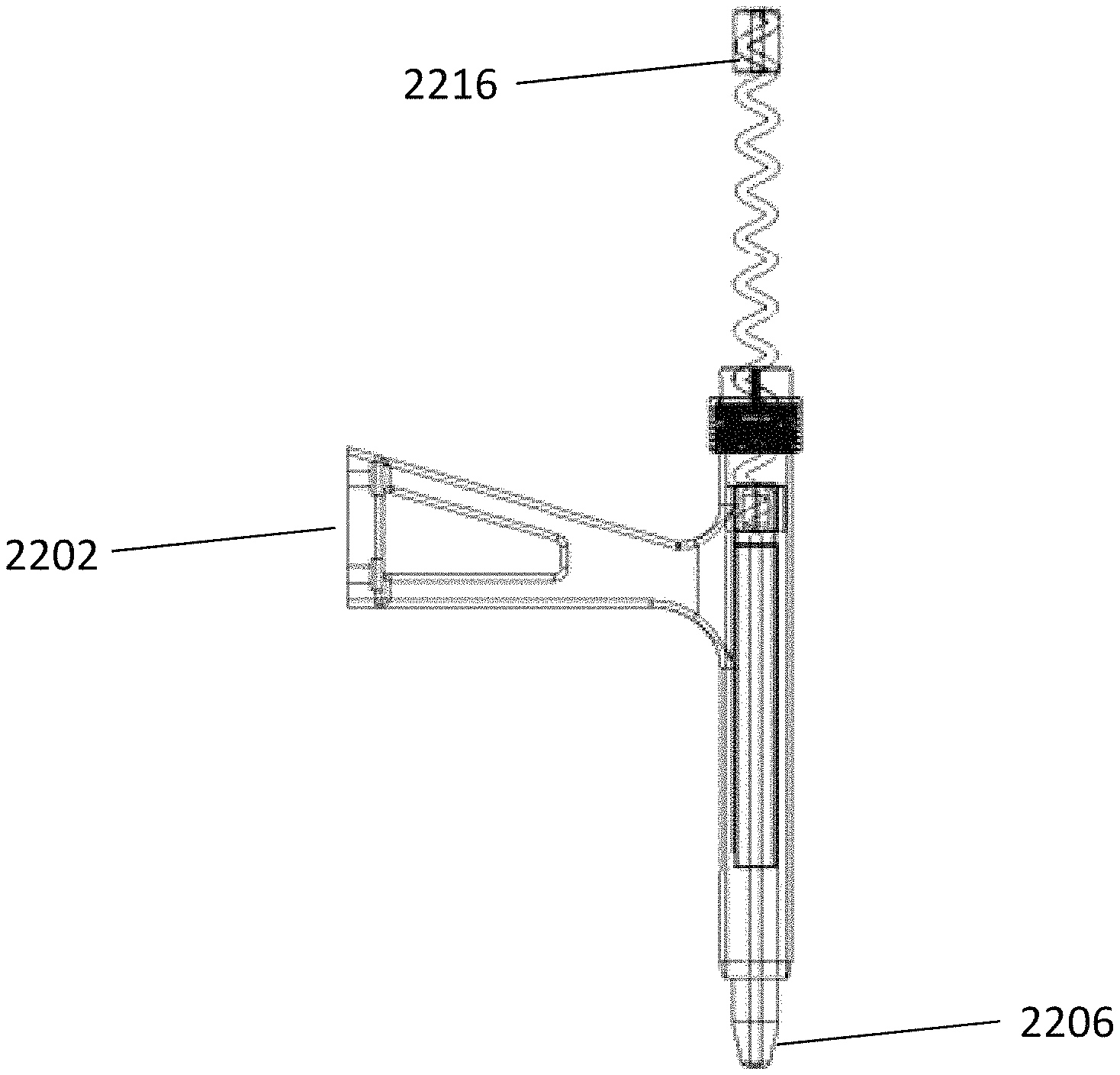
The present disclosure also provides a dilator system for a surgical robot that includes an outer sleeve, a center shank at least partially disposed within the outer sleeve, a rod at least partially disposed within the outer sleeve, an outer dilator disposed within the outer sleeve, an inner dilator disposed within the outer dilator. The center shank may be configured to advance a center pin into a bone, the rod may be configured to advance the inner dilator over the center pin, and the outer dilator may be configured to advance over the inner dilator.
DESCRIPTION OF THE DRAWINGS
FIG. 1 is an overhead view of a potential arrangement for locations of the robotic system, patient, surgeon, and other medical personnel during a surgical procedure;
FIG. 2 illustrates the robotic system including positioning of the surgical robot and the camera relative to the patient according to one embodiment;
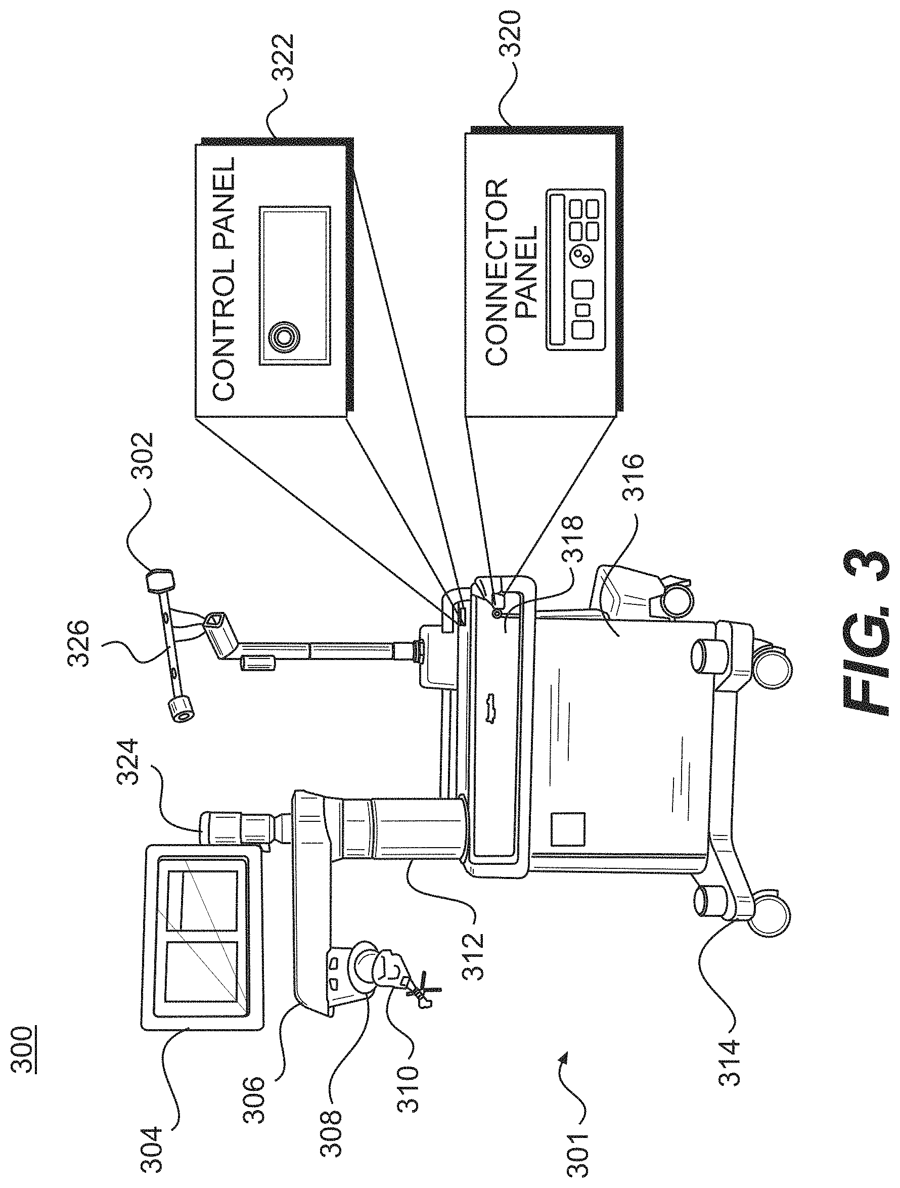
FIG. 3 illustrates a surgical robotic system in accordance with an exemplary embodiment;
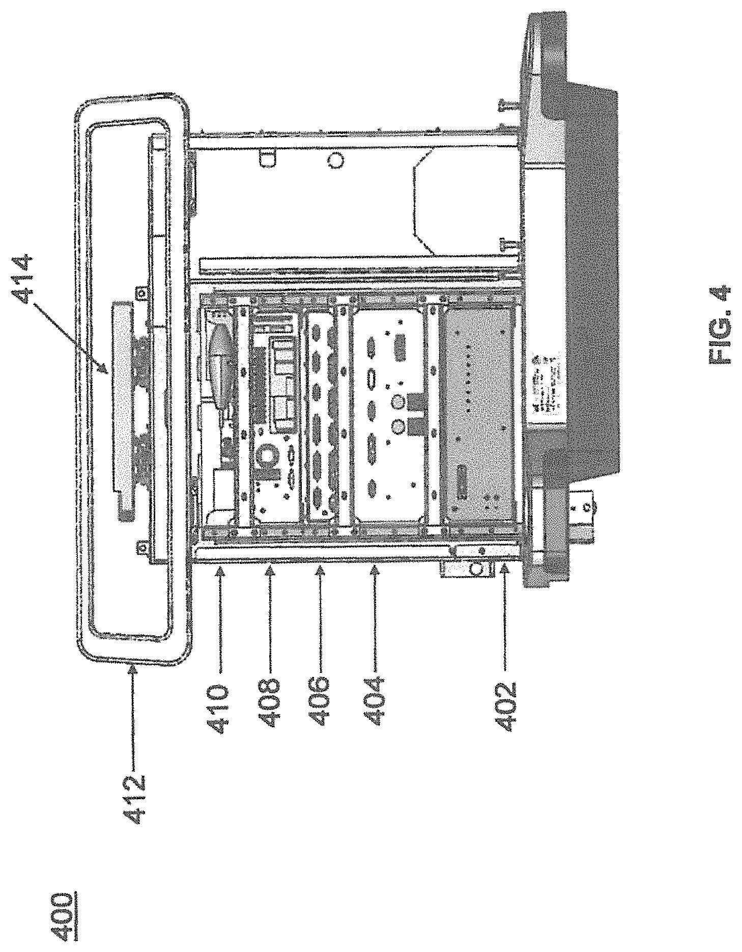
FIG. 4 illustrates a portion of a surgical robot in accordance with an exemplary embodiment;
FIG. 5 illustrates a block diagram of a surgical robot in accordance with an exemplary embodiment;
FIG. 6 illustrates a surgical robot in accordance with an exemplary embodiment;
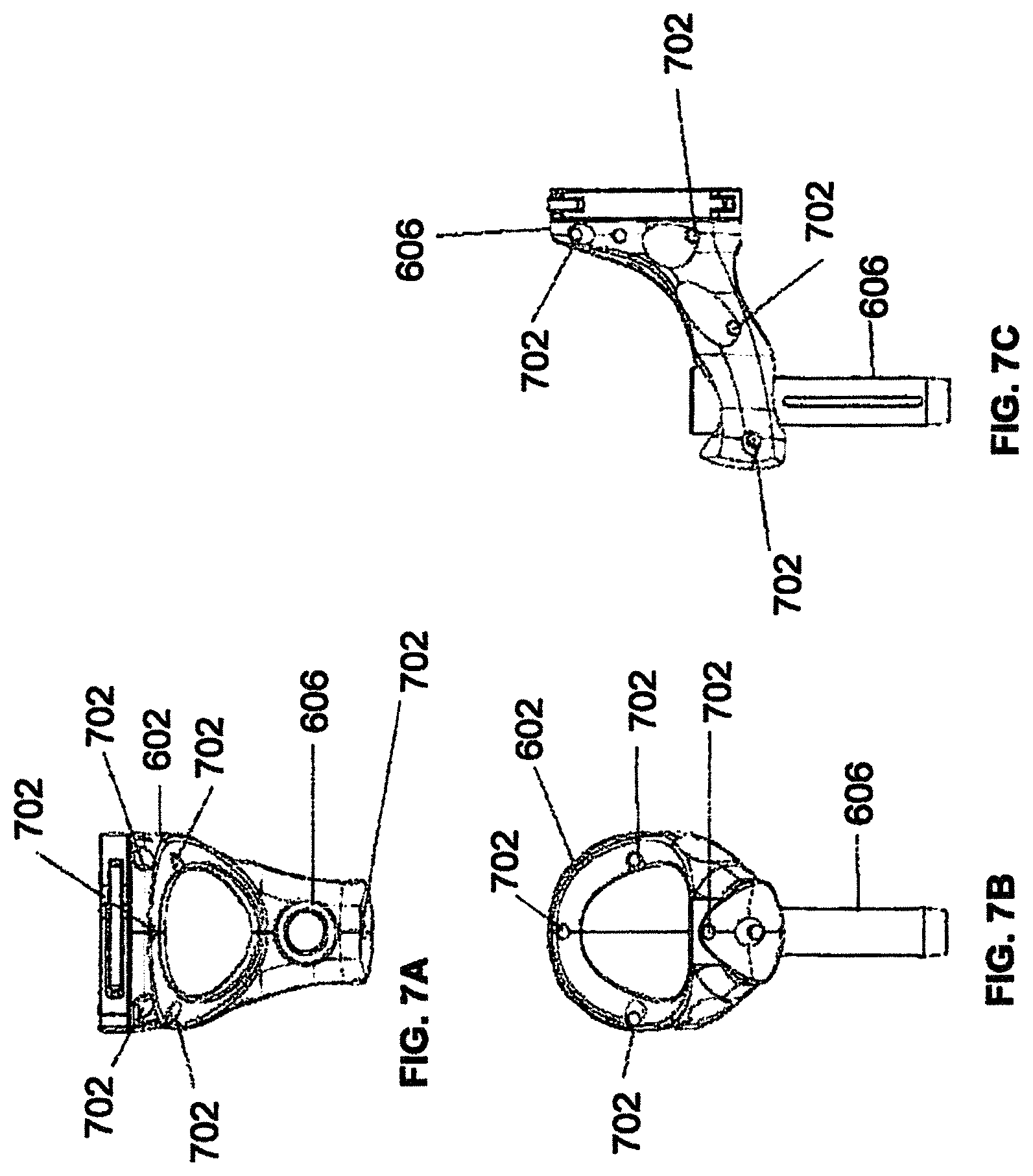
FIGS. 7A-7C illustrate an end-effector in accordance with an exemplary embodiment;
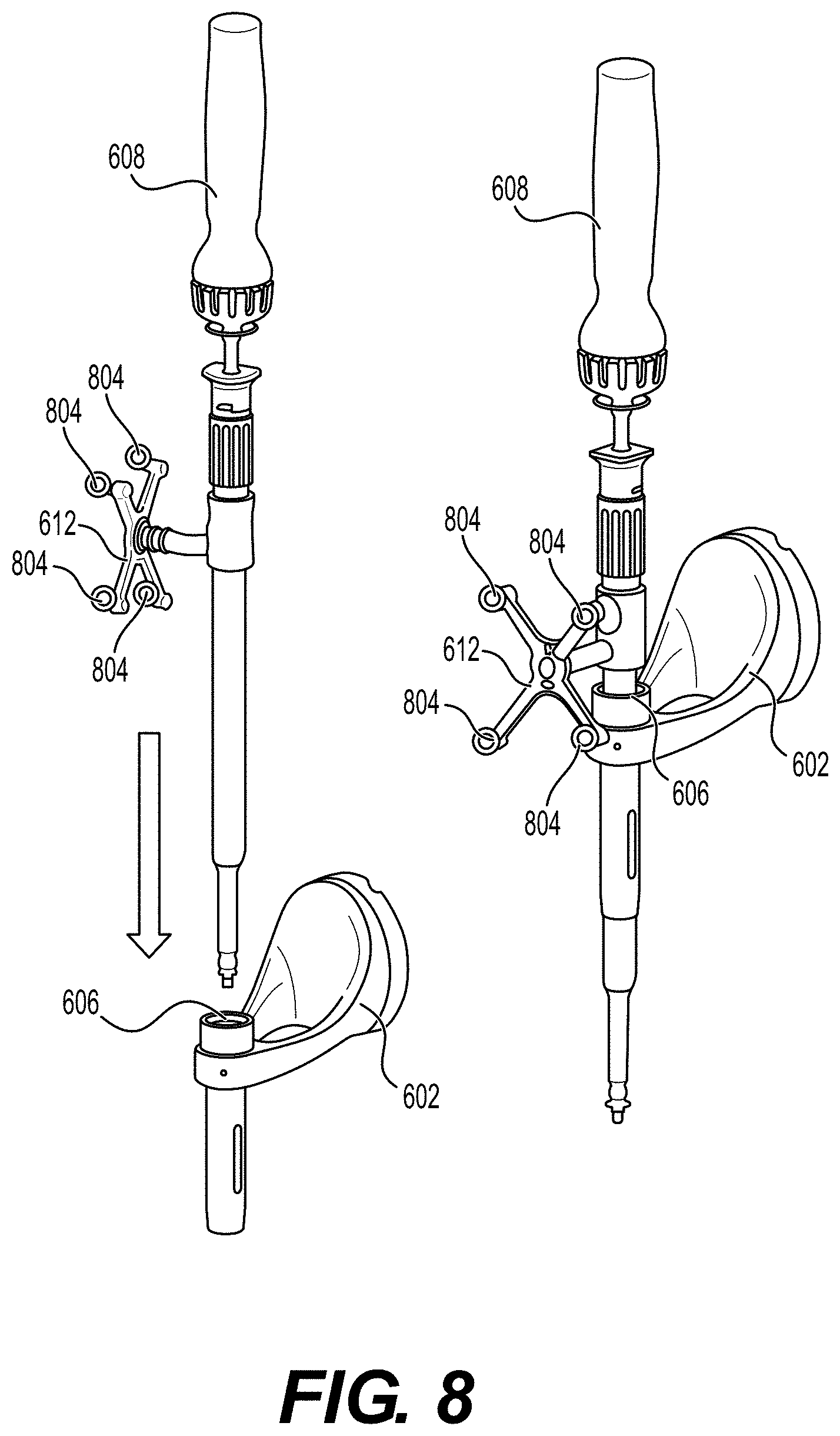
FIG. 8 illustrates a surgical instrument and the end-effector, before and after, inserting the surgical instrument into the guide tube of the end-effector according to one embodiment;
FIGS. 9A-9C illustrate portions of an end-effector and robot arm in accordance with an exemplary embodiment;
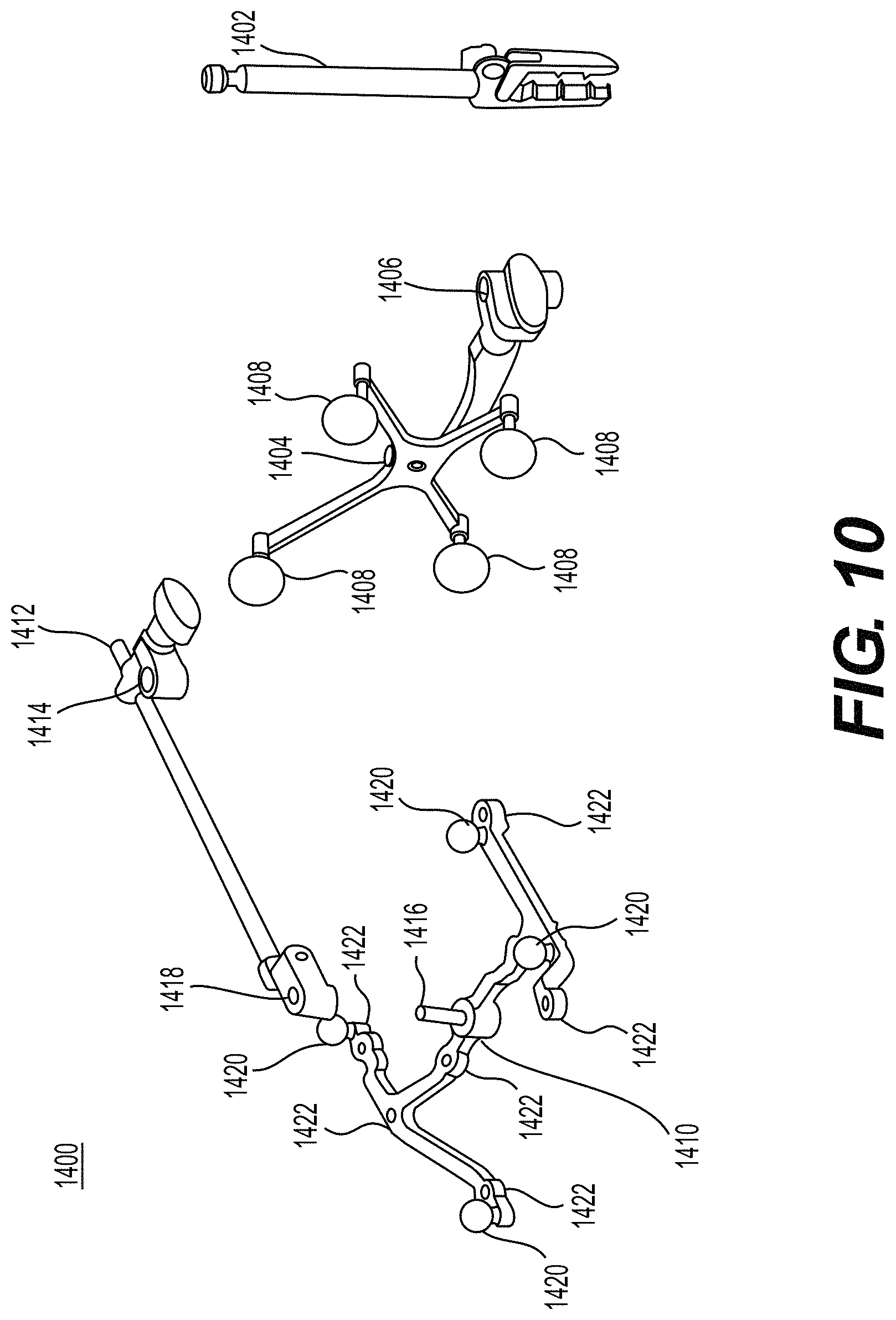
FIG. 10 illustrates a dynamic reference array, an imaging array, and other components in accordance with an exemplary embodiment;
FIG. 11 illustrates a method of registration in accordance with an exemplary embodiment;
FIG. 12A-12B illustrate embodiments of imaging devices according to exemplary embodiments;
FIG. 13A illustrates a portion of a robot including the robot arm and an end-effector in accordance with an exemplary embodiment;
FIG. 13B is a close-up view of the end-effector, with a plurality of tracking markers rigidly affixed thereon, shown in FIG. 13A;
FIG. 13C is a tool or instrument with a plurality of tracking markers rigidly affixed thereon according to one embodiment;
FIG. 14A is an alternative version of an end-effector with moveable tracking markers in a first configuration;
FIG. 14B is the end-effector shown in FIG. 14A with the moveable tracking markers in a second configuration;
FIG. 14C shows the template of tracking markers in the first configuration from FIG. 14A;
FIG. 14D shows the template of tracking markers in the second configuration from FIG. 14B;
FIG. 15A shows an alternative version of the end-effector having only a single tracking marker affixed thereto;
FIG. 15B shows the end-effector of FIG. 15A with an instrument disposed through the guide tube;
FIG. 15C shows the end-effector of FIG. 15A with the instrument in two different positions, and the resulting logic to determine if the instrument is positioned within the guide tube or outside of the guide tube;
FIG. 15D shows the end-effector of FIG. 15A with the instrument in the guide tube at two different frames and its relative distance to the single tracking marker on the guide tube;
FIG. 15E shows the end-effector of FIG. 15A relative to a coordinate system;
FIG. 16 is a block diagram of a method for navigating and moving the end-effector of the robot to a desired target trajectory;
FIGS. 17A-17B depict an instrument for inserting an expandable implant having fixed and moveable tracking markers in contracted and expanded positions, respectively;
FIGS. 18A-18B depict an instrument for inserting an articulating implant having fixed and moveable tracking markers in insertion and angled positions, respectively;
FIG. 19A depicts an embodiment of a robot with interchangeable or alternative end-effectors; and
FIG. 19B depicts an embodiment of a robot with an instrument style end-effector coupled thereto.
FIG. 20 depicts a guide tube consistent with the principles of the present disclosure.
FIG. 21 depicts a surgical tool consistent with the principles of the present disclosure.
FIG. 22 depicts a dilator mechanism consistent with the principles of the present disclosure.
FIG. 23 depicts an advancement mechanism consistent with the principles of the present disclosure.
FIG. 24 depicts certain components of the dilator mechanism consistent with the principles of the present disclosure.
FIGS. 25A and 25B depict a dilator mechanism consistent with the principles of the present disclosure.
FIGS. 26A and 26B depict a dilator mechanism consistent with the principles of the present disclosure.
FIGS. 27A-D depict a dilator mechanism consistent with the principles of the present disclosure.
FIGS. 28A-C depict a dilator mechanism consistent with the principles of the present disclosure.
DETAILED DESCRIPTION
It is to be understood that the present disclosure is not limited in its application to the details of construction and the arrangement of components set forth in the description herein or illustrated in the drawings. The teachings of the present disclosure may be used and practiced in other embodiments and practiced or carried out in various ways. Also, it is to be understood that the phraseology and terminology used herein is for the purpose of description and should not be regarded as limiting. The use of "including," "comprising," or "having" and variations thereof herein is meant to encompass the items listed thereafter and equivalents thereof as well as additional items. Unless specified or limited otherwise, the terms "mounted," "connected," "supported," and "coupled" and variations thereof are used broadly and encompass both direct and indirect mountings, connections, supports, and couplings. Further, "connected" and "coupled" are not restricted to physical or mechanical connections or couplings.
The following discussion is presented to enable a person skilled in the art to make and use embodiments of the present disclosure. Various modifications to the illustrated embodiments will be readily apparent to those skilled in the art, and the principles herein can be applied to other embodiments and applications without departing from embodiments of the present disclosure. Thus, the embodiments are not intended to be limited to embodiments shown, but are to be accorded the widest scope consistent with the principles and features disclosed herein. The following detailed description is to be read with reference to the figures, in which like elements in different figures have like reference numerals. The figures, which are not necessarily to scale, depict selected embodiments and are not intended to limit the scope of the embodiments. Skilled artisans will recognize the examples provided herein have many useful alternatives and fall within the scope of the embodiments.
Turning now to the drawing, FIGS. 1 and 2 illustrate a surgical robot system 100 in accordance with an exemplary embodiment. Surgical robot system 100 may include, for example, a surgical robot 102, one or more robot arms 104, a base 106, a display 110, an end-effector 112, for example, including a guide tube 114, and one or more tracking markers 118. The surgical robot system 100 may include a patient tracking device 116 also including one or more tracking markers 118, which is adapted to be secured directly to the patient 210 (e.g., to the bone of the patient 210). The surgical robot system 100 may also utilize a camera 200, for example, positioned on a camera stand 202. The camera stand 202 can have any suitable configuration to move, orient, and support the camera 200 in a desired position. The camera 200 may include any suitable camera or cameras, such as one or more infrared cameras (e.g., bifocal or stereophotogrammetric cameras), able to identify, for example, active and passive tracking markers 118 in a given measurement volume viewable from the perspective of the camera 200. The camera 200 may scan the given measurement volume and detect the light that comes from the markers 118 in order to identify and determine the position of the markers 118 in three-dimensions. For example, active markers 118 may include infrared-emitting markers that are activated by an electrical signal (e.g., infrared light emitting diodes (LEDs)), and passive markers 118 may include retro-reflective markers that reflect infrared light (e.g., they reflect incoming IR radiation into the direction of the incoming light), for example, emitted by illuminators on the camera 200 or other suitable device.
FIGS. 1 and 2 illustrate a potential configuration for the placement of the surgical robot system 100 in an operating room environment. For example, the robot 102 may be positioned near or next to patient 210. Although depicted near the head of the patient 210, it will be appreciated that the robot 102 can be positioned at any suitable location near the patient 210 depending on the area of the patient 210 undergoing the operation. The camera 200 may be separated from the robot system 100 and positioned at the foot of patient 210. This location allows the camera 200 to have a direct visual line of sight to the surgical field 208. Again, it is contemplated that the camera 200 may be located at any suitable position having line of sight to the surgical field 208. In the configuration shown, the surgeon 120 may be positioned across from the robot 102, but is still able to manipulate the end-effector 112 and the display 110. A surgical assistant 126 may be positioned across from the surgeon 120 again with access to both the end-effector 112 and the display 110. If desired, the locations of the surgeon 120 and the assistant 126 may be reversed. The traditional areas for the anesthesiologist 122 and the nurse or scrub tech 124 remain unimpeded by the locations of the robot 102 and camera 200.
With respect to the other components of the robot 102, the display 110 can be attached to the surgical robot 102 and in other exemplary embodiments, display 110 can be detached from surgical robot 102, either within a surgical room with the surgical robot 102, or in a remote location. End-effector 112 may be coupled to the robot arm 104 and controlled by at least one motor. In exemplary embodiments, end-effector 112 can comprise a guide tube 114, which is able to receive and orient a surgical instrument 608 (described further herein) used to perform surgery on the patient 210. As used herein, the term "end-effector" is used interchangeably with the terms "end-effectuator" and "effectuator element." Although generally shown with a guide tube 114, it will be appreciated that the end-effector 112 may be replaced with any suitable instrumentation suitable for use in surgery. In some embodiments, end-effector 112 can comprise any known structure for effecting the movement of the surgical instrument 608 in a desired manner.
The surgical robot 102 is able to control the translation and orientation of the end-effector 112. The robot 102 is able to move end-effector 112 along x-, y-, and z-axes, for example. The end-effector 112 can be configured for selective rotation about one or more of the x-, y-, and z-axis, and a Z Frame axis (such that one or more of the Euler Angles (e.g., roll, pitch, and/or yaw) associated with end-effector 112 can be selectively controlled). In some exemplary embodiments, selective control of the translation and orientation of end-effector 112 can permit performance of medical procedures with significantly improved accuracy compared to conventional robots that utilize, for example, a six degree of freedom robot arm comprising only rotational axes. For example, the surgical robot system 100 may be used to operate on patient 210, and robot arm 104 can be positioned above the body of patient 210, with end-effector 112 selectively angled relative to the z-axis toward the body of patient 210.
In some exemplary embodiments, the position of the surgical instrument 608 can be dynamically updated so that surgical robot 102 can be aware of the location of the surgical instrument 608 at all times during the procedure. Consequently, in some exemplary embodiments, surgical robot 102 can move the surgical instrument 608 to the desired position quickly without any further assistance from a physician (unless the physician so desires). In some further embodiments, surgical robot 102 can be configured to correct the path of the surgical instrument 608 if the surgical instrument 608 strays from the selected, preplanned trajectory. In some exemplary embodiments, surgical robot 102 can be configured to permit stoppage, modification, and/or manual control of the movement of end-effector 112 and/or the surgical instrument 608. Thus, in use, in exemplary embodiments, a physician or other user can operate the system 100, and has the option to stop, modify, or manually control the autonomous movement of end-effector 112 and/or the surgical instrument 608. Further details of surgical robot system 100 including the control and movement of a surgical instrument 608 by surgical robot 102 can be found in co-pending U.S. patent application Ser. No. 13/924,505, which is incorporated herein by reference in its entirety.
The robotic surgical system 100 can comprise one or more tracking markers 118 configured to track the movement of robot arm 104, end-effector 112, patient 210, and/or the surgical instrument 608 in three dimensions. In exemplary embodiments, a plurality of tracking markers 118 can be mounted (or otherwise secured) thereon to an outer surface of the robot 102, such as, for example and without limitation, on base 106 of robot 102, on robot arm 104, or on the end-effector 112. In exemplary embodiments, at least one tracking marker 118 of the plurality of tracking markers 118 can be mounted or otherwise secured to the end-effector 112. One or more tracking markers 118 can further be mounted (or otherwise secured) to the patient 210. In exemplary embodiments, the plurality of tracking markers 118 can be positioned on the patient 210 spaced apart from the surgical field 208 to reduce the likelihood of being obscured by the surgeon, surgical tools, or other parts of the robot 102. Further, one or more tracking markers 118 can be further mounted (or otherwise secured) to the surgical tools 608 (e.g., a screw driver, dilator, implant inserter, or the like). Thus, the tracking markers 118 enable each of the marked objects (e.g., the end-effector 112, the patient 210, and the surgical tools 608) to be tracked by the robot 102. In exemplary embodiments, system 100 can use tracking information collected from each of the marked objects to calculate the orientation and location, for example, of the end-effector 112, the surgical instrument 608 (e.g., positioned in the tube 114 of the end-effector 112), and the relative position of the patient 210.
The markers 118 may include radiopaque or optical markers. The markers 118 may be suitably shaped include spherical, spheroid, cylindrical, cube, cuboid, or the like. In exemplary embodiments, one or more of markers 118 may be optical markers. In some embodiments, the positioning of one or more tracking markers 118 on end-effector 112 can maximize the accuracy of the positional measurements by serving to check or verify the position of end-effector 112. Further details of surgical robot system 100 including the control, movement and tracking of surgical robot 102 and of a surgical instrument 608 can be found in co-pending U.S. patent application Ser. No. 13/924,505, which is incorporated herein by reference in its entirety.
Exemplary embodiments include one or more markers 118 coupled to the surgical instrument 608. In exemplary embodiments, these markers 118, for example, coupled to the patient 210 and surgical instruments 608, as well as markers 118 coupled to the end-effector 112 of the robot 102 can comprise conventional infrared light-emitting diodes (LEDs) or an Optotrak.RTM. diode capable of being tracked using a commercially available infrared optical tracking system such as Optotrak.RTM.. Optotrak.RTM. is a registered trademark of Northern Digital Inc., Waterloo, Ontario, Canada. In other embodiments, markers 118 can comprise conventional reflective spheres capable of being tracked using a commercially available optical tracking system such as Polaris Spectra. Polaris Spectra is also a registered trademark of Northern Digital, Inc. In an exemplary embodiment, the markers 118 coupled to the end-effector 112 are active markers which comprise infrared light-emitting diodes which may be turned on and off, and the markers 118 coupled to the patient 210 and the surgical instruments 608 comprise passive reflective spheres.
In exemplary embodiments, light emitted from and/or reflected by markers 118 can be detected by camera 200 and can be used to monitor the location and movement of the marked objects. In alternative embodiments, markers 118 can comprise a radio-frequency and/or electromagnetic reflector or transceiver and the camera 200 can include or be replaced by a radio-frequency and/or electromagnetic transceiver.
Similar to surgical robot system 100, FIG. 3 illustrates a surgical robot system 300 and camera stand 302, in a docked configuration, consistent with an exemplary embodiment of the present disclosure. Surgical robot system 300 may comprise a robot 301 including a display 304, upper arm 306, lower arm 308, end-effector 310, vertical column 312, casters 314, cabinet 316, tablet drawer 318, connector panel 320, control panel 322, and ring of information 324. Camera stand 302 may comprise camera 326. These components are described in greater with respect to FIG. 5. FIG. 3 illustrates the surgical robot system 300 in a docked configuration where the camera stand 302 is nested with the robot 301, for example, when not in use. It will be appreciated by those skilled in the art that the camera 326 and robot 301 may be separated from one another and positioned at any appropriate location during the surgical procedure, for example, as shown in FIGS. 1 and 2.
FIG. 4 illustrates a base 400 consistent with an exemplary embodiment of the present disclosure. Base 400 may be a portion of surgical robot system 300 and comprise cabinet 316. Cabinet 316 may house certain components of surgical robot system 300 including but not limited to a battery 402, a power distribution module 404, a platform interface board module 406, a computer 408, a handle 412, and a tablet drawer 414. The connections and relationship between these components is described in greater detail with respect to FIG. 5.
FIG. 5 illustrates a block diagram of certain components of an exemplary embodiment of surgical robot system 300. Surgical robot system 300 may comprise platform subsystem 502, computer subsystem 504, motion control subsystem 506, and tracking subsystem 532. Platform subsystem 502 may further comprise battery 402, power distribution module 404, platform interface board module 406, and tablet charging station 534. Computer subsystem 504 may further comprise computer 408, display 304, and speaker 536. Motion control subsystem 506 may further comprise driver circuit 508, motors 510, 512, 514, 516, 518, stabilizers 520, 522, 524, 526, end-effector 310, and controller 538. Tracking subsystem 532 may further comprise position sensor 540 and camera converter 542. System 300 may also comprise a foot pedal 544 and tablet 546.
Input power is supplied to system 300 via a power source 548 which may be provided to power distribution module 404. Power distribution module 404 receives input power and is configured to generate different power supply voltages that are provided to other modules, components, and subsystems of system 300. Power distribution module 404 may be configured to provide different voltage supplies to platform interface module 406, which may be provided to other components such as computer 408, display 304, speaker 536, driver 508 to, for example, power motors 512, 514, 516, 518 and end-effector 310, motor 510, ring 324, camera converter 542, and other components for system 300 for example, fans for cooling the electrical components within cabinet 316.
Power distribution module 404 may also provide power to other components such as tablet charging station 534 that may be located within tablet drawer 318. Tablet charging station 534 may be in wireless or wired communication with tablet 546 for charging table 546. Tablet 546 may be used by a surgeon consistent with the present disclosure and described herein.
Power distribution module 404 may also be connected to battery 402, which serves as temporary power source in the event that power distribution module 404 does not receive power from input power 548. At other times, power distribution module 404 may serve to charge battery 402 if necessary.
Other components of platform subsystem 502 may also include connector panel 320, control panel 322, and ring 324. Connector panel 320 may serve to connect different devices and components to system 300 and/or associated components and modules. Connector panel 320 may contain one or more ports that receive lines or connections from different components. For example, connector panel 320 may have a ground terminal port that may ground system 300 to other equipment, a port to connect foot pedal 544 to system 300, a port to connect to tracking subsystem 532, which may comprise position sensor 540, camera converter 542, and cameras 326 associated with camera stand 302. Connector panel 320 may also include other ports to allow USB, Ethernet, HDMI communications to other components, such as computer 408.
Control panel 322 may provide various buttons or indicators that control operation of system 300 and/or provide information regarding system 300. For example, control panel 322 may include buttons to power on or off system 300, lift or lower vertical column 312, and lift or lower stabilizers 520-526 that may be designed to engage casters 314 to lock system 300 from physically moving. Other buttons may stop system 300 in the event of an emergency, which may remove all motor power and apply mechanical brakes to stop all motion from occurring. Control panel 322 may also have indicators notifying the user of certain system conditions such as a line power indicator or status of charge for battery 402.
Ring 324 may be a visual indicator to notify the user of system 300 of different modes that system 300 is operating under and certain warnings to the user.
Computer subsystem 504 includes computer 408, display 304, and speaker 536. Computer 504 includes an operating system and software to operate system 300. Computer 504 may receive and process information from other components (for example, tracking subsystem 532, platform subsystem 502, and/or motion control subsystem 506) in order to display information to the user. Further, computer subsystem 504 may also include speaker 536 to provide audio to the user.
Tracking subsystem 532 may include position sensor 504 and converter 542. Tracking subsystem 532 may correspond to camera stand 302 including camera 326 as described with respect to FIG. 3. Position sensor 504 may be camera 326. Tracking subsystem may track the location of certain markers that are located on the different components of system 300 and/or instruments used by a user during a surgical procedure. This tracking may be conducted in a manner consistent with the present disclosure including the use of infrared technology that tracks the location of active or passive elements, such as LEDs or reflective markers, respectively. The location, orientation, and position of structures having these types of markers may be provided to computer 408 which may be shown to a user on display 304. For example, a surgical instrument 608 having these types of markers and tracked in this manner (which may be referred to as a navigational space) may be shown to a user in relation to a three dimensional image of a patient's anatomical structure.
Motion control subsystem 506 may be configured to physically move vertical column 312, upper arm 306, lower arm 308, or rotate end-effector 310. The physical movement may be conducted through the use of one or more motors 510-518. For example, motor 510 may be configured to vertically lift or lower vertical column 312. Motor 512 may be configured to laterally move upper arm 308 around a point of engagement with vertical column 312 as shown in FIG. 3. Motor 514 may be configured to laterally move lower arm 308 around a point of engagement with upper arm 308 as shown in FIG. 3. Motors 516 and 518 may be configured to move end-effector 310 in a manner such that one may control the roll and one may control the tilt, thereby providing multiple angles that end-effector 310 may be moved. These movements may be achieved by controller 538 which may control these movements through load cells disposed on end-effector 310 and activated by a user engaging these load cells to move system 300 in a desired manner.
Moreover, system 300 may provide for automatic movement of vertical column 312, upper arm 306, and lower arm 308 through a user indicating on display 304 (which may be a touchscreen input device) the location of a surgical instrument or component on three dimensional image of the patient's anatomy on display 304. The user may initiate this automatic movement by stepping on foot pedal 544 or some other input means.
FIG. 6 illustrates a surgical robot system 600 consistent with an exemplary embodiment. Surgical robot system 600 may comprise end-effector 602, robot arm 604, guide tube 606, instrument 608, and robot base 610. Instrument tool 608 may be attached to a tracking array 612 including one or more tracking markers (such as markers 118) and have an associated trajectory 614. Trajectory 614 may represent a path of movement that instrument tool 608 is configured to travel once it is positioned through or secured in guide tube 606, for example, a path of insertion of instrument tool 608 into a patient. In an exemplary operation, robot base 610 may be configured to be in electronic communication with robot arm 604 and end-effector 602 so that surgical robot system 600 may assist a user (for example, a surgeon) in operating on the patient 210. Surgical robot system 600 may be consistent with previously described surgical robot system 100 and 300.
A tracking array 612 may be mounted on instrument 608 to monitor the location and orientation of instrument tool 608. The tracking array 612 may be attached to an instrument 608 and may comprise tracking markers 804. As best seen in FIG. 8, tracking markers 804 may be, for example, light emitting diodes and/or other types of reflective markers (e.g., markers 118 as described elsewhere herein). The tracking devices may be one or more line of sight devices associated with the surgical robot system. As an example, the tracking devices may be one or more cameras 200, 326 associated with the surgical robot system 100, 300 and may also track tracking array 612 for a defined domain or relative orientations of the instrument 608 in relation to the robot arm 604, the robot base 610, end-effector 602, and/or the patient 210. The tracking devices may be consistent with those structures described in connection with camera stand 302 and tracking subsystem 532.
FIGS. 7A, 7B, and 7C illustrate a top view, front view, and side view, respectively, of end-effector 602 consistent with an exemplary embodiment. End-effector 602 may comprise one or more tracking markers 702. Tracking markers 702 may be light emitting diodes or other types of active and passive markers, such as tracking markers 118 that have been previously described. In an exemplary embodiment, the tracking markers 702 are active infrared-emitting markers that are activated by an electrical signal (e.g., infrared light emitting diodes (LEDs)). Thus, tracking markers 702 may be activated such that the infrared markers 702 are visible to the camera 200, 326 or may be deactivated such that the infrared markers 702 are not visible to the camera 200, 326. Thus, when the markers 702 are active, the end-effector 602 may be controlled by the system 100, 300, 600, and when the markers 702 are deactivated, the end-effector 602 may be locked in position and unable to be moved by the system 100, 300, 600.
Markers 702 may be disposed on or within end-effector 602 in a manner such that the markers 702 are visible by one or more cameras 200, 326 or other tracking devices associated with the surgical robot system 100, 300, 600. The camera 200, 326 or other tracking devices may track end-effector 602 as it moves to different positions and viewing angles by following the movement of tracking markers 702. The location of markers 702 and/or end-effector 602 may be shown on a display 110, 304 associated with the surgical robot system 100, 300, 600, for example, display 110 as shown in FIG. 2 and/or display 304 shown in FIG. 3. This display 110, 304 may allow a user to ensure that end-effector 602 is in a desirable position in relation to robot arm 604, robot base 610, the patient 210, and/or the user.
For example, as shown in FIG. 7A, markers 702 may be placed around the surface of end-effector 602 so that a tracking device placed away from the surgical field 208 and facing toward the robot 102, 301 and the camera 200, 326 is able to view at least 3 of the markers 702 through a range of common orientations of the end-effector 602 relative to the tracking device 100, 300, 600. For example, distribution of markers 702 in this way allows end-effector 602 to be monitored by the tracking devices when end-effector 602 is translated and rotated in the surgical field 208.
In addition, in exemplary embodiments, end-effector 602 may be equipped with infrared (IR) receivers that can detect when an external camera 200, 326 is getting ready to read markers 702. Upon this detection, end-effector 602 may then illuminate markers 702. The detection by the IR receivers that the external camera 200, 326 is ready to read markers 702 may signal the need to synchronize a duty cycle of markers 702, which may be light emitting diodes, to an external camera 200, 326. This may also allow for lower power consumption by the robotic system as a whole, whereby markers 702 would only be illuminated at the appropriate time instead of being illuminated continuously. Further, in exemplary embodiments, markers 702 may be powered off to prevent interference with other navigation tools, such as different types of surgical instruments 608.
FIG. 8 depicts one type of surgical instrument 608 including a tracking array 612 and tracking markers 804. Tracking markers 804 may be of any type described herein including but not limited to light emitting diodes or reflective spheres. Markers 804 are monitored by tracking devices associated with the surgical robot system 100, 300, 600 and may be one or more of the line of sight cameras 200, 326. The cameras 200, 326 may track the location of instrument 608 based on the position and orientation of tracking array 612 and markers 804. A user, such as a surgeon 120, may orient instrument 608 in a manner so that tracking array 612 and markers 804 are sufficiently recognized by the tracking device or camera 200, 326 to display instrument 608 and markers 804 on, for example, display 110 of the exemplary surgical robot system.
The manner in which a surgeon 120 may place instrument 608 into guide tube 606 of the end-effector 602 and adjust the instrument 608 is evident in FIG. 8. The hollow tube or guide tube 114, 606 of the end-effector 112, 310, 602 is sized and configured to receive at least a portion of the surgical instrument 608. The guide tube 114, 606 is configured to be oriented by the robot arm 104 such that insertion and trajectory for the surgical instrument 608 is able to reach a desired anatomical target within or upon the body of the patient 210. The surgical instrument 608 may include at least a portion of a generally cylindrical instrument. Although a screw driver is exemplified as the surgical tool 608, it will be appreciated that any suitable surgical tool 608 may be positioned by the end-effector 602. By way of example, the surgical instrument 608 may include one or more of a guide wire, cannula, a retractor, a drill, a reamer, a screw driver, an insertion tool, a removal tool, or the like. Although the hollow tube 114, 606 is generally shown as having a cylindrical configuration, it will be appreciated by those of skill in the art that the guide tube 114, 606 may have any suitable shape, size and configuration desired to accommodate the surgical instrument 608 and access the surgical site.
FIGS. 9A-9C illustrate end-effector 602 and a portion of robot arm 604 consistent with an exemplary embodiment. End-effector 602 may further comprise body 1202 and clamp 1204. Clamp 1204 may comprise handle 1206, balls 1208, spring 1210, and lip 1212. Robot arm 604 may further comprise depressions 1214, mounting plate 1216, lip 1218, and magnets 1220.
End-effector 602 may mechanically interface and/or engage with the surgical robot system and robot arm 604 through one or more couplings. For example, end-effector 602 may engage with robot arm 604 through a locating coupling and/or a reinforcing coupling. Through these couplings, end-effector 602 may fasten with robot arm 604 outside a flexible and sterile barrier. In an exemplary embodiment, the locating coupling may be a magnetically kinematic mount and the reinforcing coupling may be a five bar over center clamping linkage.
With respect to the locating coupling, robot arm 604 may comprise mounting plate 1216, which may be non-magnetic material, one or more depressions 1214, lip 1218, and magnets 1220. Magnet 1220 is mounted below each of depressions 1214. Portions of clamp 1204 may comprise magnetic material and be attracted by one or more magnets 1220. Through the magnetic attraction of clamp 1204 and robot arm 604, balls 1208 become seated into respective depressions 1214. For example, balls 1208 as shown in FIG. 9B would be seated in depressions 1214 as shown in FIG. 9A. This seating may be considered a magnetically-assisted kinematic coupling. Magnets 1220 may be configured to be strong enough to support the entire weight of end-effector 602 regardless of the orientation of end-effector 602. The locating coupling may be any style of kinematic mount that uniquely restrains six degrees of freedom.
With respect to the reinforcing coupling, portions of clamp 1204 may be configured to be a fixed ground link and as such clamp 1204 may serve as a five bar linkage. Closing clamp handle 1206 may fasten end-effector 602 to robot arm 604 as lip 1212 and lip 1218 engage clamp 1204 in a manner to secure end-effector 602 and robot arm 604. When clamp handle 1206 is closed, spring 1210 may be stretched or stressed while clamp 1204 is in a locked position. The locked position may be a position that provides for linkage past center. Because of a closed position that is past center, the linkage will not open absent a force applied to clamp handle 1206 to release clamp 1204. Thus, in a locked position end-effector 602 may be robustly secured to robot arm 604.
Spring 1210 may be a curved beam in tension. Spring 1210 may be comprised of a material that exhibits high stiffness and high yield strain such as virgin PEEK (poly-ether-ether-ketone). The linkage between end-effector 602 and robot arm 604 may provide for a sterile barrier between end-effector 602 and robot arm 604 without impeding fastening of the two couplings.
The reinforcing coupling may be a linkage with multiple spring members. The reinforcing coupling may latch with a cam or friction based mechanism. The reinforcing coupling may also be a sufficiently powerful electromagnet that will support fastening end-effector 102 to robot arm 604. The reinforcing coupling may be a multi-piece collar completely separate from either end-effector 602 and/or robot arm 604 that slips over an interface between end-effector 602 and robot arm 604 and tightens with a screw mechanism, an over center linkage, or a cam mechanism.
Referring to FIGS. 10 and 11, prior to or during a surgical procedure, certain registration procedures may be conducted in order to track objects and a target anatomical structure of the patient 210 both in a navigation space and an image space. In order to conduct such registration, a registration system 1400 may be used as illustrated in FIG. 10.
In order to track the position of the patient 210, a patient tracking device 116 may include a patient fixation instrument 1402 to be secured to a rigid anatomical structure of the patient 210 and a dynamic reference base (DRB) 1404 may be securely attached to the patient fixation instrument 1402. For example, patient fixation instrument 1402 may be inserted into opening 1406 of dynamic reference base 1404. Dynamic reference base 1404 may contain markers 1408 that are visible to tracking devices, such as tracking subsystem 532. These markers 1408 may be optical markers or reflective spheres, such as tracking markers 118, as previously discussed herein.
Patient fixation instrument 1402 is attached to a rigid anatomy of the patient 210 and may remain attached throughout the surgical procedure. In an exemplary embodiment, patient fixation instrument 1402 is attached to a rigid area of the patient 210, for example, a bone that is located away from the targeted anatomical structure subject to the surgical procedure. In order to track the targeted anatomical structure, dynamic reference base 1404 is associated with the targeted anatomical structure through the use of a registration fixture that is temporarily placed on or near the targeted anatomical structure in order to register the dynamic reference base 1404 with the location of the targeted anatomical structure.
A registration fixture 1410 is attached to patient fixation instrument 1402 through the use of a pivot arm 1412. Pivot arm 1412 is attached to patient fixation instrument 1402 by inserting patient fixation instrument 1402 through an opening 1414 of registration fixture 1410. Pivot arm 1412 is attached to registration fixture 1410 by, for example, inserting a knob 1416 through an opening 1418 of pivot arm 1412.
Using pivot arm 1412, registration fixture 1410 may be placed over the targeted anatomical structure and its location may be determined in an image space and navigation space using tracking markers 1420 and/or fiducials 1422 on registration fixture 1410. Registration fixture 1410 may contain a collection of markers 1420 that are visible in a navigational space (for example, markers 1420 may be detectable by tracking subsystem 532). Tracking markers 1420 may be optical markers visible in infrared light as previously described herein. Registration fixture 1410 may also contain a collection of fiducials 1422, for example, such as bearing balls, that are visible in an imaging space (for example, a three dimension CT image). As described in greater detail with respect to FIG. 11, using registration fixture 1410, the targeted anatomical structure may be associated with dynamic reference base 1404 thereby allowing depictions of objects in the navigational space to be overlaid on images of the anatomical structure. Dynamic reference base 1404, located at a position away from the targeted anatomical structure, may become a reference point thereby allowing removal of registration fixture 1410 and/or pivot arm 1412 from the surgical area.
FIG. 11 provides an exemplary method 1500 for registration consistent with the present disclosure. Method 1500 begins at step 1502 wherein a graphical representation (or image(s)) of the targeted anatomical structure may be imported into system 100, 300 600, for example computer 408. The graphical representation may be three dimensional CT or a fluoroscope scan of the targeted anatomical structure of the patient 210 which includes registration fixture 1410 and a detectable imaging pattern of fiducials 1420.
At step 1504, an imaging pattern of fiducials 1420 is detected and registered in the imaging space and stored in computer 408. Optionally, at this time at step 1506, a graphical representation of the registration fixture 1410 may be overlaid on the images of the targeted anatomical structure.
At step 1508, a navigational pattern of registration fixture 1410 is detected and registered by recognizing markers 1420. Markers 1420 may be optical markers that are recognized in the navigation space through infrared light by tracking subsystem 532 via position sensor 540. Thus, the location, orientation, and other information of the targeted anatomical structure is registered in the navigation space. Therefore, registration fixture 1410 may be recognized in both the image space through the use of fiducials 1422 and the navigation space through the use of markers 1420. At step 1510, the registration of registration fixture 1410 in the image space is transferred to the navigation space. This transferal is done, for example, by using the relative position of the imaging pattern of fiducials 1422 compared to the position of the navigation pattern of markers 1420.
At step 1512, registration of the navigation space of registration fixture 1410 (having been registered with the image space) is further transferred to the navigation space of dynamic registration array 1404 attached to patient fixture instrument 1402. Thus, registration fixture 1410 may be removed and dynamic reference base 1404 may be used to track the targeted anatomical structure in both the navigation and image space because the navigation space is associated with the image space.
At steps 1514 and 1516, the navigation space may be overlaid on the image space and objects with markers visible in the navigation space (for example, surgical instruments 608 with optical markers 804). The objects may be tracked through graphical representations of the surgical instrument 608 on the images of the targeted anatomical structure.
FIGS. 12A-12B illustrate imaging devices 1304 that may be used in conjunction with robot systems 100, 300, 600 to acquire pre-operative, intra-operative, post-operative, and/or real-time image data of patient 210. Any appropriate subject matter may be imaged for any appropriate procedure using the imaging system 1304. The imaging system 1304 may be any imaging device such as imaging device 1306 and/or a C-arm 1308 device. It may be desirable to take x-rays of patient 210 from a number of different positions, without the need for frequent manual repositioning of patient 210 which may be required in an x-ray system. As illustrated in FIG. 12A, the imaging system 1304 may be in the form of a C-arm 1308 that includes an elongated C-shaped member terminating in opposing distal ends 1312 of the "C" shape. C-shaped member 1130 may further comprise an x-ray source 1314 and an image receptor 1316. The space within C-arm 1308 of the arm may provide room for the physician to attend to the patient substantially free of interference from x-ray support structure 1318. As illustrated in FIG. 12B, the imaging system may include imaging device 1306 having a gantry housing 1324 attached to a support structure imaging device support structure 1328, such as a wheeled mobile cart 1330 with wheels 1332, which may enclose an image capturing portion, not illustrated. The image capturing portion may include an x-ray source and/or emission portion and an x-ray receiving and/or image receiving portion, which may be disposed about one hundred and eighty degrees from each other and mounted on a rotor (not illustrated) relative to a track of the image capturing portion. The image capturing portion may be operable to rotate three hundred and sixty degrees during image acquisition. The image capturing portion may rotate around a central point and/or axis, allowing image data of patient 210 to be acquired from multiple directions or in multiple planes. Although certain imaging systems 1304 are exemplified herein, it will be appreciated that any suitable imaging system may be selected by one of ordinary skill in the art.
Turning now to FIGS. 13A-13C, the surgical robot system 100, 300, 600 relies on accurate positioning of the end-effector 112, 602, surgical instruments 608, and/or the patient 210 (e.g., patient tracking device 116) relative to the desired surgical area. In the embodiments shown in FIGS. 13A-13C, the tracking markers 118, 804 are rigidly attached to a portion of the instrument 608 and/or end-effector 112.
FIG. 13A depicts part of the surgical robot system 100 with the robot 102 including base 106, robot arm 104, and end-effector 112. The other elements, not illustrated, such as the display, cameras, etc. may also be present as described herein. FIG. 13B depicts a close-up view of the end-effector 112 with guide tube 114 and a plurality of tracking markers 118 rigidly affixed to the end-effector 112. In this embodiment, the plurality of tracking markers 118 are attached to the guide tube 112. FIG. 13C depicts an instrument 608 (in this case, a probe 608A) with a plurality of tracking markers 804 rigidly affixed to the instrument 608. As described elsewhere herein, the instrument 608 could include any suitable surgical instrument, such as, but not limited to, guide wire, cannula, a retractor, a drill, a reamer, a screw driver, an insertion tool, a removal tool, or the like.
When tracking an instrument 608, end-effector 112, or other object to be tracked in 3D, an array of tracking markers 118, 804 may be rigidly attached to a portion of the tool 608 or end-effector 112. Preferably, the tracking markers 118, 804 are attached such that the markers 118, 804 are out of the way (e.g., not impeding the surgical operation, visibility, etc.). The markers 118, 804 may be affixed to the instrument 608, end-effector 112, or other object to be tracked, for example, with an array 612. Usually three or four markers 118, 804 are used with an array 612. The array 612 may include a linear section, a cross piece, and may be asymmetric such that the markers 118, 804 are at different relative positions and locations with respect to one another. For example, as shown in FIG. 13C, a probe 608A with a 4-marker tracking array 612 is shown, and FIG. 13B depicts the end-effector 112 with a different 4-marker tracking array 612.
In FIG. 13C, the tracking array 612 functions as the handle 620 of the probe 608A. Thus, the four markers 804 are attached to the handle 620 of the probe 608A, which is out of the way of the shaft 622 and tip 624. Stereophotogrammetric tracking of these four markers 804 allows the instrument 608 to be tracked as a rigid body and for the tracking system 100, 300, 600 to precisely determine the position of the tip 624 and the orientation of the shaft 622 while the probe 608A is moved around in front of tracking cameras 200, 326.
To enable automatic tracking of one or more tools 608, end-effector 112, or other object to be tracked in 3D (e.g., multiple rigid bodies), the markers 118, 804 on each tool 608, end-effector 112, or the like, are arranged asymmetrically with a known inter-marker spacing. The reason for asymmetric alignment is so that it is unambiguous which marker 118, 804 corresponds to a particular location on the rigid body and whether markers 118, 804 are being viewed from the front or back, i.e., mirrored. For example, if the markers 118, 804 were arranged in a square on the tool 608 or end-effector 112, it would be unclear to the system 100, 300, 600 which marker 118, 804 corresponded to which corner of the square. For example, for the probe 608A, it would be unclear which marker 804 was closest to the shaft 622. Thus, it would be unknown which way the shaft 622 was extending from the array 612. Accordingly, each array 612 and thus each tool 608, end-effector 112, or other object to be tracked should have a unique marker pattern to allow it to be distinguished from other tools 608 or other objects being tracked. Asymmetry and unique marker patterns allow the system 100, 300, 600 to detect individual markers 118, 804 then to check the marker spacing against a stored template to determine which tool 608, end effector 112, or other object they represent. Detected markers 118, 804 can then be sorted automatically and assigned to each tracked object in the correct order. Without this information, rigid body calculations could not then be performed to extract key geometric information, for example, such as tool tip 624 and alignment of the shaft 622, unless the user manually specified which detected marker 118, 804 corresponded to which position on each rigid body. These concepts are commonly known to those skilled in the methods of 3D optical tracking.
Turning now to FIGS. 14A-14D, an alternative version of an end-effector 912 with moveable tracking markers 918A-918D is shown. In FIG. 14A, an array with moveable tracking markers 918A-918D are shown in a first configuration, and in FIG. 14B the moveable tracking markers 918A-918D are shown in a second configuration, which is angled relative to the first configuration. FIG. 14C shows the template of the tracking markers 918A-918D, for example, as seen by the cameras 200, 326 in the first configuration of FIG. 14A; and FIG. 14D shows the template of tracking markers 918A-918D, for example, as seen by the cameras 200, 326 in the second configuration of FIG. 14B.
In this embodiment, 4-marker array tracking is contemplated wherein the markers 918A-918D are not all in fixed position relative to the rigid body and instead, one or more of the array markers 918A-918D can be adjusted, for example, during testing, to give updated information about the rigid body that is being tracked without disrupting the process for automatic detection and sorting of the tracked markers 918A-918D.
When tracking any tool, such as a guide tube 914 connected to the end effector 912 of a robot system 100, 300, 600, the tracking array's primary purpose is to update the position of the end effector 912 in the camera coordinate system. When using the rigid system, for example, as shown in FIG. 13B, the array 612 of reflective markers 118 rigidly extend from the guide tube 114. Because the tracking markers 118 are rigidly connected, knowledge of the marker locations in the camera coordinate system also provides exact location of the centerline, tip, and tail of the guide tube 114 in the camera coordinate system. Typically, information about the position of the end effector 112 from such an array 612 and information about the location of a target trajectory from another tracked source are used to calculate the required moves that must be input for each axis of the robot 102 that will move the guide tube 114 into alignment with the trajectory and move the tip to a particular location along the trajectory vector.
Sometimes, the desired trajectory is in an awkward or unreachable location, but if the guide tube 114 could be swiveled, it could be reached. For example, a very steep trajectory pointing away from the base 106 of the robot 102 might be reachable if the guide tube 114 could be swiveled upward beyond the limit of the pitch (wrist up-down angle) axis, but might not be reachable if the guide tube 114 is attached parallel to the plate connecting it to the end of the wrist. To reach such a trajectory, the base 106 of the robot 102 might be moved or a different end effector 112 with a different guide tube attachment might be exchanged with the working end effector. Both of these solutions may be time consuming and cumbersome.
As best seen in FIGS. 14A and 14B, if the array 908 is configured such that one or more of the markers 918A-918D are not in a fixed position and instead, one or more of the markers 918A-918D can be adjusted, swiveled, pivoted, or moved, the robot 102 can provide updated information about the object being tracked without disrupting the detection and tracking process. For example, one of the markers 918A-918D may be fixed in position and the other markers 918A-918D may be moveable; two of the markers 918A-918D may be fixed in position and the other markers 918A-918D may be moveable; three of the markers 918A-918D may be fixed in position and the other marker 918A-918D may be moveable; or all of the markers 918A-918D may be moveable.
In the embodiment shown in FIGS. 14A and 14B, markers 918A, 918B are rigidly connected directly to a base 906 of the end-effector 912, and markers 918C, 918D are rigidly connected to the tube 914. Similar to array 612, array 908 may be provided to attach the markers 918A-918D to the end-effector 912, instrument 608, or other object to be tracked. In this case, however, the array 908 is comprised of a plurality of separate components. For example, markers 918A, 918B may be connected to the base 906 with a first array 908A, and markers 918C, 918D may be connected to the guide tube 914 with a second array 908B. Marker 918A may be affixed to a first end of the first array 908A and marker 918B may be separated a linear distance and affixed to a second end of the first array 908A. While first array 908 is substantially linear, second array 908B has a bent or V-shaped configuration, with respective root ends, connected to the guide tube 914, and diverging therefrom to distal ends in a V-shape with marker 918C at one distal end and marker 918D at the other distal end. Although specific configurations are exemplified herein, it will be appreciated that other asymmetric designs including different numbers and types of arrays 908A, 908B and different arrangements, numbers, and types of markers 918A-918D are contemplated.
The guide tube 914 may be moveable, swivelable, or pivotable relative to the base 906, for example, across a hinge 920 or other connector to the base 906. Thus, markers 918C, 918D are moveable such that when the guide tube 914 pivots, swivels, or moves, markers 918C, 918D also pivot, swivel, or move. As best seen in FIG. 14A, guide tube 914 has a longitudinal axis 916 which is aligned in a substantially normal or vertical orientation such that markers 918A-918D have a first configuration. Turning now to FIG. 14B, the guide tube 914 is pivoted, swiveled, or moved such that the longitudinal axis 916 is now angled relative to the vertical orientation such that markers 918A-918D have a second configuration, different from the first configuration.
In contrast to the embodiment described for FIGS. 14A-14D, if a swivel existed between the guide tube 914 and the arm 104 (e.g., the wrist attachment) with all four markers 918A-918D remaining attached rigidly to the guide tube 914 and this swivel was adjusted by the user, the robotic system 100, 300, 600 would not be able to automatically detect that the guide tube 914 orientation had changed. The robotic system 100, 300, 600 would track the positions of the marker array 908 and would calculate incorrect robot axis moves assuming the guide tube 914 was attached to the wrist (the robot arm 104) in the previous orientation. By keeping one or more markers 918A-918D (e.g., two markers 918C, 918D) rigidly on the tube 914 and one or more markers 918A-918D (e.g., two markers 918A, 918B) across the swivel, automatic detection of the new position becomes possible and correct robot moves are calculated based on the detection of a new tool or end-effector 112, 912 on the end of the robot arm 104.
One or more of the markers 918A-918D are configured to be moved, pivoted, swiveled, or the like according to any suitable means. For example, the markers 918A-918D may be moved by a hinge 920, such as a clamp, spring, lever, slide, toggle, or the like, or any other suitable mechanism for moving the markers 918A-918D individually or in combination, moving the arrays 908A, 908B individually or in combination, moving any portion of the end-effector 912 relative to another portion, or moving any portion of the tool 608 relative to another portion.
As shown in FIGS. 14A and 14B, the array 908 and guide tube 914 may become reconfigurable by simply loosening the clamp or hinge 920, moving part of the array 908A, 908B relative to the other part 908A, 908B, and retightening the hinge 920 such that the guide tube 914 is oriented in a different position. For example, two markers 918C, 918D may be rigidly interconnected with the tube 914 and two markers 918A, 918B may be rigidly interconnected across the hinge 920 to the base 906 of the end-effector 912 that attaches to the robot arm 104. The hinge 920 may be in the form of a clamp, such as a wing nut or the like, which can be loosened and retightened to allow the user to quickly switch between the first configuration (FIG. 14A) and the second configuration (FIG. 14B).
The cameras 200, 326 detect the markers 918A-918D, for example, in one of the templates identified in FIGS. 14C and 14D. If the array 908 is in the first configuration (FIG. 14A) and tracking cameras 200, 326 detect the markers 918A-918D, then the tracked markers match Array Template 1 as shown in FIG. 14C. If the array 908 is the second configuration (FIG. 14B) and tracking cameras 200, 326 detect the same markers 918A-918D, then the tracked markers match Array Template 2 as shown in FIG. 14D. Array Template 1 and Array Template 2 are recognized by the system 100, 300, 600 as two distinct tools, each with its own uniquely defined spatial relationship between guide tube 914, markers 918A-918D, and robot attachment. The user could therefore adjust the position of the end-effector 912 between the first and second configurations without notifying the system 100, 300, 600 of the change and the system 100, 300, 600 would appropriately adjust the movements of the robot 102 to stay on trajectory.
In this embodiment, there are two assembly positions in which the marker array matches unique templates that allow the system 100, 300, 600 to recognize the assembly as two different tools or two different end effectors. In any position of the swivel between or outside of these two positions (namely, Array Template 1 and Array Template 2 shown in FIGS. 14C and 14D, respectively), the markers 918A-918D would not match any template and the system 100, 300, 600 would not detect any array present despite individual markers 918A-918D being detected by cameras 200, 326, with the result being the same as if the markers 918A-918D were temporarily blocked from view of the cameras 200, 326. It will be appreciated that other array templates may exist for other configurations, for example, identifying different instruments 608 or other end-effectors 112, 912, etc.
In the embodiment described, two discrete assembly positions are shown in FIGS. 14A and 14B. It will be appreciated, however, that there could be multiple discrete positions on a swivel joint, linear joint, combination of swivel and linear joints, pegboard, or other assembly where unique marker templates may be created by adjusting the position of one or more markers 918A-918D of the array relative to the others, with each discrete position matching a particular template and defining a unique tool 608 or end-effector 112, 912 with different known attributes. In addition, although exemplified for end effector 912, it will be appreciated that moveable and fixed markers 918A-918D may be used with any suitable instrument 608 or other object to be tracked.
When using an external 3D tracking system 100, 300, 600 to track a full rigid body array of three or more markers attached to a robot's end effector 112 (for example, as depicted in FIGS. 13A and 13B), it is possible to directly track or to calculate the 3D position of every section of the robot 102 in the coordinate system of the cameras 200, 326. The geometric orientations of joints relative to the tracker are known by design, and the linear or angular positions of joints are known from encoders for each motor of the robot 102, fully defining the 3D positions of all of the moving parts from the end effector 112 to the base 116. Similarly, if a tracker were mounted on the base 106 of the robot 102 (not shown), it is likewise possible to track or calculate the 3D position of every section of the robot 102 from base 106 to end effector 112 based on known joint geometry and joint positions from each motor's encoder.
In some situations, it may be desirable to track the positions of all segments of the robot 102 from fewer than three markers 118 rigidly attached to the end effector 112. Specifically, if a tool 608 is introduced into the guide tube 114, it may be desirable to track full rigid body motion of the robot 902 with only one additional marker 118 being tracked.
Turning now to FIGS. 15A-15E, an alternative version of an end-effector 1012 having only a single tracking marker 1018 is shown. End-effector 1012 may be similar to the other end-effectors described herein, and may include a guide tube 1014 extending along a longitudinal axis 1016. A single tracking marker 1018, similar to the other tracking markers described herein, may be rigidly affixed to the guide tube 1014. This single marker 1018 can serve the purpose of adding missing degrees of freedom to allow full rigid body tracking and/or can serve the purpose of acting as a surveillance marker to ensure that assumptions about robot and camera positioning are valid.
The single tracking marker 1018 may be attached to the robotic end effector 1012 as a rigid extension to the end effector 1012 that protrudes in any convenient direction and does not obstruct the surgeon's view. The tracking marker 1018 may be affixed to the guide tube 1014 or any other suitable location of on the end-effector 1012. When affixed to the guide tube 1014, the tracking marker 1018 may be positioned at a location between first and second ends of the guide tube 1014. For example, in FIG. 15A, the single tracking marker 1018 is shown as a reflective sphere mounted on the end of a narrow shaft 1017 that extends forward from the guide tube 1014 and is positioned longitudinally above a mid-point of the guide tube 1014 and below the entry of the guide tube 1014. This position allows the marker 1018 to be generally visible by cameras 200, 326 but also would not obstruct vision of the surgeon 120 or collide with other tools or objects in the vicinity of surgery. In addition, the guide tube 1014 with the marker 1018 in this position is designed for the marker array on any tool 608 introduced into the guide tube 1014 to be visible at the same time as the single marker 1018 on the guide tube 1014 is visible.
As shown in FIG. 15B, when a snugly fitting tool or instrument 608 is placed within the guide tube 1014, the instrument 608 becomes mechanically constrained in 4 of 6 degrees of freedom. That is, the instrument 608 cannot be rotated in any direction except about the longitudinal axis 1016 of the guide tube 1014 and the instrument 608 cannot be translated in any direction except along the longitudinal axis 1016 of the guide tube 1014. In other words, the instrument 608 can only be translated along and rotated about the centerline of the guide tube 1014. If two more parameters are known, such as (1) an angle of rotation about the longitudinal axis 1016 of the guide tube 1014; and (2) a position along the guide tube 1014, then the position of the end effector 1012 in the camera coordinate system becomes fully defined.
Referring now to FIG. 15C, the system 100, 300, 600 should be able to know when a tool 608 is actually positioned inside of the guide tube 1014 and is not instead outside of the guide tube 1014 and just somewhere in view of the cameras 200, 326. The tool 608 has a longitudinal axis or centerline 616 and an array 612 with a plurality of tracked markers 804. The rigid body calculations may be used to determine where the centerline 616 of the tool 608 is located in the camera coordinate system based on the tracked position of the array 612 on the tool 608.
The fixed normal (perpendicular) distance D.sub.F from the single marker 1018 to the centerline or longitudinal axis 1016 of the guide tube 1014 is fixed and is known geometrically, and the position of the single marker 1018 can be tracked. Therefore, when a detected distance D.sub.D from tool centerline 616 to single marker 1018 matches the known fixed distance D.sub.F from the guide tube centerline 1016 to the single marker 1018, it can be determined that the tool 608 is either within the guide tube 1014 (centerlines 616, 1016 of tool 608 and guide tube 1014 coincident) or happens to be at some point in the locus of possible positions where this distance D.sub.D matches the fixed distance D.sub.F. For example, in FIG. 15C, the normal detected distance D.sub.D from tool centerline 616 to the single marker 1018 matches the fixed distance D.sub.F from guide tube centerline 1016 to the single marker 1018 in both frames of data (tracked marker coordinates) represented by the transparent tool 608 in two positions, and thus, additional considerations may be needed to determine when the tool 608 is located in the guide tube 1014.
Turning now to FIG. 15D, programmed logic can be used to look for frames of tracking data in which the detected distance D.sub.D from tool centerline 616 to single marker 1018 remains fixed at the correct length despite the tool 608 moving in space by more than some minimum distance relative to the single sphere 1018 to satisfy the condition that the tool 608 is moving within the guide tube 1014. For example, a first frame F1 may be detected with the tool 608 in a first position and a second frame F2 may be detected with the tool 608 in a second position (namely, moved linearly with respect to the first position). The markers 804 on the tool array 612 may move by more than a given amount (e.g., more than 5 mm total) from the first frame F1 to the second frame F2. Even with this movement, the detected distance D.sub.D from the tool centerline vector C' to the single marker 1018 is substantially identical in both the first frame F1 and the second frame F2.
Logistically, the surgeon 120 or user could place the tool 608 within the guide tube 1014 and slightly rotate it or slide it down into the guide tube 1014 and the system 100, 300, 600 would be able to detect that the tool 608 is within the guide tube 1014 from tracking of the five markers (four markers 804 on tool 608 plus single marker 1018 on guide tube 1014). Knowing that the tool 608 is within the guide tube 1014, all 6 degrees of freedom may be calculated that define the position and orientation of the robotic end effector 1012 in space. Without the single marker 1018, even if it is known with certainty that the tool 608 is within the guide tube 1014, it is unknown where the guide tube 1014 is located along the tool's centerline vector C' and how the guide tube 1014 is rotated relative to the centerline vector C'.
With emphasis on FIG. 15E, the presence of the single marker 1018 being tracked as well as the four markers 804 on the tool 608, it is possible to construct the centerline vector C' of the guide tube 1014 and tool 608 and the normal vector through the single marker 1018 and through the centerline vector C'. This normal vector has an orientation that is in a known orientation relative to the forearm of the robot distal to the wrist (in this example, oriented parallel to that segment) and intersects the centerline vector C' at a specific fixed position. For convenience, three mutually orthogonal vectors k', j', i' can be constructed, as shown in FIG. 15E, defining rigid body position and orientation of the guide tube 1014. One of the three mutually orthogonal vectors k' is constructed from the centerline vector C', the second vector j' is constructed from the normal vector through the single marker 1018, and the third vector i' is the vector cross product of the first and second vectors k', j'. The robot's joint positions relative to these vectors k', j', i' are known and fixed when all joints are at zero, and therefore rigid body calculations can be used to determine the location of any section of the robot relative to these vectors k', j', i' when the robot is at a home position. During robot movement, if the positions of the tool markers 804 (while the tool 608 is in the guide tube 1014) and the position of the single marker 1018 are detected from the tracking system, and angles/linear positions of each joint are known from encoders, then position and orientation of any section of the robot can be determined.
In some embodiments, it may be useful to fix the orientation of the tool 608 relative to the guide tube 1014. For example, the end effector guide tube 1014 may be oriented in a particular position about its axis 1016 to allow machining or implant positioning. Although the orientation of anything attached to the tool 608 inserted into the guide tube 1014 is known from the tracked markers 804 on the tool 608, the rotational orientation of the guide tube 1014 itself in the camera coordinate system is unknown without the additional tracking marker 1018 (or multiple tracking markers in other embodiments) on the guide tube 1014. This marker 1018 provides essentially a "clock position" from -180.degree. to +180.degree. based on the orientation of the marker 1018 relative to the centerline vector C'. Thus, the single marker 1018 can provide additional degrees of freedom to allow full rigid body tracking and/or can act as a surveillance marker to ensure that assumptions about the robot and camera positioning are valid.
FIG. 16 is a block diagram of a method 1100 for navigating and moving the end-effector 1012 (or any other end-effector described herein) of the robot 102 to a desired target trajectory. Another use of the single marker 1018 on the robotic end effector 1012 or guide tube 1014 is as part of the method 1100 enabling the automated safe movement of the robot 102 without a full tracking array attached to the robot 102. This method 1100 functions when the tracking cameras 200, 326 do not move relative to the robot 102 (i.e., they are in a fixed position), the tracking system's coordinate system and robot's coordinate system are co-registered, and the robot 102 is calibrated such that the position and orientation of the guide tube 1014 can be accurately determined in the robot's Cartesian coordinate system based only on the encoded positions of each robotic axis.
For this method 1100, the coordinate systems of the tracker and the robot must be co-registered, meaning that the coordinate transformation from the tracking system's Cartesian coordinate system to the robot's Cartesian coordinate system is needed. For convenience, this coordinate transformation can be a 4.times.4 matrix of translations and rotations that is well known in the field of robotics. This transformation will be termed Tcr to refer to "transformation--camera to robot". Once this transformation is known, any new frame of tracking data, which is received as x,y,z coordinates in vector form for each tracked marker, can be multiplied by the 4.times.4 matrix and the resulting x,y,z coordinates will be in the robot's coordinate system. To obtain Tcr, a full tracking array on the robot is tracked while it is rigidly attached to the robot at a location that is known in the robot's coordinate system, then known rigid body methods are used to calculate the transformation of coordinates. It should be evident that any tool 608 inserted into the guide tube 1014 of the robot 102 can provide the same rigid body information as a rigidly attached array when the additional marker 1018 is also read. That is, the tool 608 need only be inserted to any position within the guide tube 1014 and at any rotation within the guide tube 1014, not to a fixed position and orientation. Thus, it is possible to determine Tcr by inserting any tool 608 with a tracking array 612 into the guide tube 1014 and reading the tool's array 612 plus the single marker 1018 of the guide tube 1014 while at the same time determining from the encoders on each axis the current location of the guide tube 1014 in the robot's coordinate system.
Logic for navigating and moving the robot 102 to a target trajectory is provided in the method 1100 of FIG. 16. Before entering the loop 1102, it is assumed that the transformation Tcr was previously stored. Thus, before entering loop 1102, in step 1104, after the robot base 106 is secured, greater than or equal to one frame of tracking data of a tool inserted in the guide tube while the robot is static is stored; and in step 1106, the transformation of robot guide tube position from camera coordinates to robot coordinates Tcr is calculated from this static data and previous calibration data. Tcr should remain valid as long as the cameras 200, 326 do not move relative to the robot 102. If the cameras 200, 326 move relative to the robot 102, and Tcr needs to be re-obtained, the system 100, 300, 600 can be made to prompt the user to insert a tool 608 into the guide tube 1014 and then automatically perform the necessary calculations.
In the flowchart of method 1100, each frame of data collected consists of the tracked position of the DRB 1404 on the patient 210, the tracked position of the single marker 1018 on the end effector 1014, and a snapshot of the positions of each robotic axis. From the positions of the robot's axes, the location of the single marker 1018 on the end effector 1012 is calculated. This calculated position is compared to the actual position of the marker 1018 as recorded from the tracking system. If the values agree, it can be assured that the robot 102 is in a known location. The transformation Tcr is applied to the tracked position of the DRB 1404 so that the target for the robot 102 can be provided in terms of the robot's coordinate system. The robot 102 can then be commanded to move to reach the target.
After steps 1104, 1106, loop 1102 includes step 1108 receiving rigid body information for DRB 1404 from the tracking system; step 1110 transforming target tip and trajectory from image coordinates to tracking system coordinates; and step 1112 transforming target tip and trajectory from camera coordinates to robot coordinates (apply Tcr). Loop 1102 further includes step 1114 receiving a single stray marker position for robot from tracking system; and step 1116 transforming the single stray marker from tracking system coordinates to robot coordinates (apply stored Tcr). Loop 1102 also includes step 1118 determining current location of the single robot marker 1018 in the robot coordinate system from forward kinematics. The information from steps 1116 and 1118 is used to determine step 1120 whether the stray marker coordinates from transformed tracked position agree with the calculated coordinates being less than a given tolerance. If yes, proceed to step 1122, calculate and apply robot move to target x, y, z and trajectory. If no, proceed to step 1124, halt and require full array insertion into guide tube 1014 before proceeding; step 1126 after array is inserted, recalculate Tcr; and then proceed to repeat steps 1108, 1114, and 1118.
This method 1100 has advantages over a method in which the continuous monitoring of the single marker 1018 to verify the location is omitted. Without the single marker 1018, it would still be possible to determine the position of the end effector 1012 using Tcr and to send the end-effector 1012 to a target location but it would not be possible to verify that the robot 102 was actually in the expected location. For example, if the cameras 200, 326 had been bumped and Tcr was no longer valid, the robot 102 would move to an erroneous location. For this reason, the single marker 1018 provides value with regard to safety.
For a given fixed position of the robot 102, it is theoretically possible to move the tracking cameras 200, 326 to a new location in which the single tracked marker 1018 remains unmoved since it is a single point, not an array. In such a case, the system 100, 300, 600 would not detect any error since there would be agreement in the calculated and tracked locations of the single marker 1018. However, once the robot's axes caused the guide tube 1012 to move to a new location, the calculated and tracked positions would disagree and the safety check would be effective.
The term "surveillance marker" may be used, for example, in reference to a single marker that is in a fixed location relative to the DRB 1404. In this instance, if the DRB 1404 is bumped or otherwise dislodged, the relative location of the surveillance marker changes and the surgeon 120 can be alerted that there may be a problem with navigation. Similarly, in the embodiments described herein, with a single marker 1018 on the robot's guide tube 1014, the system 100, 300, 600 can continuously check whether the cameras 200, 326 have moved relative to the robot 102. If registration of the tracking system's coordinate system to the robot's coordinate system is lost, such as by cameras 200, 326 being bumped or malfunctioning or by the robot malfunctioning, the system 100, 300, 600 can alert the user and corrections can be made. Thus, this single marker 1018 can also be thought of as a surveillance marker for the robot 102.
It should be clear that with a full array permanently mounted on the robot 102 (e.g., the plurality of tracking markers 702 on end-effector 602 shown in FIGS. 7A-7C) such functionality of a single marker 1018 as a robot surveillance marker is not needed because it is not required that the cameras 200, 326 be in a fixed position relative to the robot 102, and Tcr is updated at each frame based on the tracked position of the robot 102. Reasons to use a single marker 1018 instead of a full array are that the full array is more bulky and obtrusive, thereby blocking the surgeon's view and access to the surgical field 208 more than a single marker 1018, and line of sight to a full array is more easily blocked than line of sight to a single marker 1018.
Turning now to FIGS. 17A-17B and 18A-18B, instruments 608, such as implant holders 608B, 608C, are depicted which include both fixed and moveable tracking markers 804, 806. The implant holders 608B, 608C may have a handle 620 and an outer shaft 622 extending from the handle 620. The shaft 622 may be positioned substantially perpendicular to the handle 620, as shown, or in any other suitable orientation. An inner shaft 626 may extend through the outer shaft 622 with a knob 628 at one end. Implant 10, 12 connects to the shaft 622, at the other end, at tip 624 of the implant holder 608B, 608C using typical connection mechanisms known to those of skill in the art. The knob 628 may be rotated, for example, to expand or articulate the implant 10, 12. U.S. Pat. Nos. 8,709,086 and 8,491,659, which are incorporated by reference herein, describe expandable fusion devices and methods of installation.
When tracking the tool 608, such as implant holder 608B, 608C, the tracking array 612 may contain a combination of fixed markers 804 and one or more moveable markers 806 which make up the array 612 or is otherwise attached to the implant holder 608B, 608C. The navigation array 612 may include at least one or more (e.g., at least two) fixed position markers 804, which are positioned with a known location relative to the implant holder instrument 608B, 608C. These fixed markers 804 would not be able to move in any orientation relative to the instrument geometry and would be useful in defining where the instrument 608 is in space. In addition, at least one marker 806 is present which can be attached to the array 612 or the instrument itself which is capable of moving within a pre-determined boundary (e.g., sliding, rotating, etc.) relative to the fixed markers 804. The system 100, 300, 600 (e.g., the software) correlates the position of the moveable marker 806 to a particular position, orientation, or other attribute of the implant 10 (such as height of an expandable interbody spacer shown in FIG. 17A-17B or angle of an articulating interbody spacer shown in FIGS. 18A-18B). Thus, the system and/or the user can determine the height or angle of the implant 10, 12 based on the location of the moveable marker 806.
In the embodiment shown in FIGS. 17A-17B, four fixed markers 804 are used to define the implant holder 608B and a fifth moveable marker 806 is able to slide within a pre-determined path to provide feedback on the implant height (e.g., a contracted position or an expanded position). FIG. 17A shows the expandable spacer 10 at its initial height, and FIG. 17B shows the spacer 10 in the expanded state with the moveable marker 806 translated to a different position. In this case, the moveable marker 806 moves closer to the fixed markers 804 when the implant 10 is expanded, although it is contemplated that this movement may be reversed or otherwise different. The amount of linear translation of the marker 806 would correspond to the height of the implant 10. Although only two positions are shown, it would be possible to have this as a continuous function whereby any given expansion height could be correlated to a specific position of the moveable marker 806.
Turning now to FIGS. 18A-18B, four fixed markers 804 are used to define the implant holder 608C and a fifth, moveable marker 806 is configured to slide within a pre-determined path to provide feedback on the implant articulation angle. FIG. 18A shows the articulating spacer 12 at its initial linear state, and FIG. 18B shows the spacer 12 in an articulated state at some offset angle with the moveable marker 806 translated to a different position. The amount of linear translation of the marker 806 would correspond to the articulation angle of the implant 12. Although only two positions are shown, it would be possible to have this as a continuous function whereby any given articulation angle could be correlated to a specific position of the moveable marker 806.
In these embodiments, the moveable marker 806 slides continuously to provide feedback about an attribute of the implant 10, 12 based on position. It is also contemplated that there may be discreet positions that the moveable marker 806 must be in which would also be able to provide further information about an implant attribute. In this case, each discreet configuration of all markers 804, 806 correlates to a specific geometry of the implant holder 608B, 608C and the implant 10, 12 in a specific orientation or at a specific height. In addition, any motion of the moveable marker 806 could be used for other variable attributes of any other type of navigated implant.
Although depicted and described with respect to linear movement of the moveable marker 806, the moveable marker 806 should not be limited to just sliding as there may be applications where rotation of the marker 806 or other movements could be useful to provide information about the implant 10, 12. Any relative change in position between the set of fixed markers 804 and the moveable marker 806 could be relevant information for the implant 10, 12 or other device. In addition, although expandable and articulating implants 10, 12 are exemplified, the instrument 608 could work with other medical devices and materials, such as spacers, cages, plates, fasteners, nails, screws, rods, pins, wire structures, sutures, anchor clips, staples, stents, bone grafts, biologics, cements, or the like.
Turning now to FIG. 19A, it is envisioned that the robot end-effector 112 is interchangeable with other types of end-effectors 112. Moreover, it is contemplated that each end-effector 112 may be able to perform one or more functions based on a desired surgical procedure. For example, the end-effector 112 having a guide tube 114 may be used for guiding an instrument 608 as described herein. In addition, end-effector 112 may be replaced with a different or alternative end-effector 112 that controls a surgical device, instrument, or implant, for example.
The alternative end-effector 112 may include one or more devices or instruments coupled to and controllable by the robot. By way of non-limiting example, the end-effector 112, as depicted in FIG. 19A, may comprise a retractor (for example, one or more retractors disclosed in U.S. Pat. Nos. 8,992,425 and 8,968,363) or one or more mechanisms for inserting or installing surgical devices such as expandable intervertebral fusion devices (such as expandable implants exemplified in U.S. Pat. Nos. 8,845,734; 9,510,954; and 9,456,903), stand-alone intervertebral fusion devices (such as implants exemplified in U.S. Pat. Nos. 9,364,343 and 9,480,579), expandable corpectomy devices (such as corpectomy implants exemplified in U.S. Pat. Nos. 9,393,128 and 9,173,747), articulating spacers (such as implants exemplified in U.S. Pat. No. 9,259,327), facet prostheses (such as devices exemplified in U.S. Pat. No. 9,539,031), laminoplasty devices (such as devices exemplified in U.S. Pat. No. 9,486,253), spinous process spacers (such as implants exemplified in U.S. Pat. No. 9,592,082), inflatables, fasteners including polyaxial screws, uniplanar screws, pedicle screws, posted screws, and the like, bone fixation plates, rod constructs and revision devices (such as devices exemplified in U.S. Pat. No. 8,882,803), artificial and natural discs, motion preserving devices and implants, spinal cord stimulators (such as devices exemplified in U.S. Pat. No. 9,440,076), and other surgical devices. The end-effector 112 may include one or instruments directly or indirectly coupled to the robot for providing bone cement, bone grafts, living cells, pharmaceuticals, or other deliverable to a surgical target. The end-effector 112 may also include one or more instruments designed for performing a discectomy, kyphoplasty, vertebrostenting, dilation, or other surgical procedure.
The end-effector itself and/or the implant, device, or instrument may include one or more markers 118 such that the location and position of the markers 118 may be identified in three-dimensions. It is contemplated that the markers 118 may include active or passive markers 118, as described herein, that may be directly or indirectly visible to the cameras 200. Thus, one or more markers 118 located on an implant 10, for example, may provide for tracking of the implant 10 before, during, and after implantation.
As shown in FIG. 19B, the end-effector 112 may include an instrument 608 or portion thereof that is coupled to the robot arm 104 (for example, the instrument 608 may be coupled to the robot arm 104 by the coupling mechanism shown in FIGS. 9A-9C) and is controllable by the robot system 100. Thus, in the embodiment shown in FIG. 19B, the robot system 100 is able to insert implant 10 into a patient and expand or contract the expandable implant 10. Accordingly, the robot system 100 may be configured to assist a surgeon or to operate partially or completely independently thereof. Thus, it is envisioned that the robot system 100 may be capable of controlling each alternative end-effector 112 for its specified function or surgical procedure.
Turning now to FIGS. 20 and 21, FIG. 20 depicts a guide tube 2000 and FIG. 21 depicts a surgical tool 2002 consistent with the principles of the present disclosure. Guide tube 2000 may include internal threading 2004 and surgical tool 2002 may include external threading 2006 that matches internal threading 2004.
One reason for providing a threaded attachment between guide tube 2000 and surgical tool 2002 is to aid in driving an implant (such as a screw) into bone to prevent stripping and/or improper purchase. Substantial driving power to screws and other tools such as awls, drills, needles or probes is provided by means of matching internal threads on an end-effector (via guide tube 2000 and threads 2004) and external threads 2006 on the surgical tool. Using the interlocking power of the threads 2004 and 2006 may allow the end-effector to assist in driving the tools into hard tissues such as bone during operation.
In addition to providing an increased ability to exert longitudinal force, the threading also provides a more uniform forward thrust than is possible during freehand screw insertion. For example, when a surgeon drives a pointed awl through bone, the awl is likely to jump suddenly forward when it exits the bone due to the decreased tissue resistance and the inability of the surgeon to react rapidly to decrease the amount of force that they are exerting. With the threaded interface, the rate of advancement is controlled. Although there may be a sudden recoil of tissue when applied force changes, the tool's forward advancement remains at a fixed rate. By providing force feedback to the robotic arm, this tissue recoil can also be countered by automatic servo control of the robot instructing it to back up in such a circumstance. For example, when applying a forward thrust through bone on an awl, the tissue resistance might be high and the bone might be flexing elastically backward in the direction of thrust. Once the awl penetrates all the way through the bone, the elastic tension might cause the piece of bone to move forward against the direction of thrust, sliding suddenly up the awl like a skewer. If the robot is continuously monitoring applied force, it can use the force feedback to respond when a sudden drop in resistance beyond some triggering threshold such as 10% is felt, assuming that the 10% drop means penetration has occurred. At the point of penetration, the robot could then switch to a mode that would use the applied force feedback to control the position of the end effector along the trajectory (thrust) vector, moving backward under feedback control to a point of zero forward or reverse force and preventing soft tissue damage.
Robotically controlled guide tube 2000 is threaded on its interior wall (threads 2004 shown as dotted lines in FIG. 20). Threads 2004 mate with matching threads 2006 on the exterior surface of the surgical tool 2002. By incorporating threads 2004 into guide tube 2000 and threads 2006 into a tool such as a screwdriver and then matching the pitch of threads 2004 and 2006 to that of a screw attached to the end of the screwdriver and being inserted into a patient, the screw would be forced to advance when surgical tool 2002 is rotated. If threads 2004 and 2006 have a finer or coarser pitch than the threads of the screw being inserted, the screw may strip (shear) in the bone as it advances. To ensure that the screw advances at the correct rate, the pitch of threads 2004 and 2006 can be selected to match the pitch of the screw itself. Different interchangeable guide tubes and mating tools could be provided to the user, who could manually select the guide tube and tool to match the pitch of the screw being used. Alternatively, an auto tool changer could automatically select the appropriate threading to match the screw selected through software and automatically load the tool on to the end effector of the robot. Also, an insert that slides into the guide tube could be inserted automatically or manually that would have correct threading. Similarly, an external sleeve shaped as a cylindrical threaded shell could be automatically or manually attached to the outside of a tool with correct threading for the screw being inserted.
In the scenario discussed above, tool 2002 when used with thread pitch matching the pitch of the screw being inserted is less likely to strip the screw by rotating it without advancing, which may occur with a freehand screw insertion when a tool in a guide tube is allowed to freely move along a longitudinal axis of a guide tube. Additionally, due to the use of the robotic system, the user may leverage the rigidity of the threads and the force of the robotic arm to help drive the screw or tool downward and into the bone more forcefully and evenly.
Corresponding the pitches of the threads of guide tube, tool, and the screw may ensure that the screw receives an enhanced ability to drive into the bone. This force enhancement may be further assisted by the force of the robotic arm itself. By using the robotic arm's power to help force the tool downward along the trajectory path into the bone, the effectiveness of the hole preparation and screw insertion increases and the surgeon's concern about the possibility of stripping the screw and wasting materials or harming the patient reduces.
In addition, guide tube 2000 may be provided with a mechanism that may selectively allow or prevent rotational movement of the tool and screw during operation. A rotational bearing placed in series at a distal end of the threaded portion of the tool, proximal to the tip of the tool, may restrict the motion of the tool tip to a purely non-rotational advancement or withdrawal along the linear path while the proximal portion of the tool is being rotated. Such a rotational bearing may be disposed for tools that should not rotationally move such as a dilator, needle, awl, or corded drill, which should not spin while it is being advanced.
Turning now to FIGS. 22-28C, a robotically controlled dilator system 2200 and various components thereof are illustrated and will be described.
FIG. 22 depicts dilator system 2200 in a partially extended state. Dilator system 2200 may include a mount 2202, a center pin 2204, an inner dilator 2206, an outer dilator 2208, and outer sleeve 2210, handles 2212, a threaded cap 2214, a corkscrew rod 2228, a corkscrew rod grip 2216 and a center shaft 2218. One reason for dilator system 2200 may be to provide separate, fine, and uniform control of two or more components of a surgical tool, such as a dilator, by using concentric mount points that can attach to the same drill. With independent control of multiple components of the tool, a surgeon can force down or retract one portion of the tool without affecting the position of a second portion of the tool, and vice versa.
In FIG. 22, controlled dilator system 2200 may allow the surgeon to advance dilator sleeves and a central shaft independently on an end effector. For example, mount 2202 may be attached to a robotic arm in order to securely anchor dilator system 2200 in position and at a trajectory in relation to a patient. Center pin 2204 may be advanced into bone by rotating central shaft 2218, which may be threaded and advance through system 2200 as described in greater detail below. Inner dilator may be advanced over center pin 2204 by rotating corkscrew rod 2228 via corkscrew rod grip 2216. Outer dilator 2208 may be advanced over inner dilator 2206 by pushing down on handles 2212. In an exemplary method of operation, a surgeon may attach a cannulated drill either over the central shaft 2218 near the proximal end of central shaft 2218 or on the corkscrew rod grip 2216, with the central shaft passing through the cannulated drill, to advance center pin 2204 or inner dilator 2206, respectively. Outer dilator 2208 may be manually advanced by the surgeon by pushing down on handles 2212. Pulling back up on handles 2212 may retract outer dilator 2208 or keep outer dilator 2208 extended, as described in greater detail below.
Controlled dilator system 2200 may help to circumvent the issue of a surgeon being unable to control mechanisms of a tool independently, such as lowering one mechanism without altering the position of another. Lowering each mechanism independently if needed and through a threaded drive mechanism gives the surgeon finer and more uniform control during surgery, and using concentric mounting points activated via a shared drill may allow for a simplified system of engagement.
Referring to FIG. 23, threaded cap 2214 is illustrated in greater detail. Threaded cap 2214 may be an anchor point allowing for independent control of inner dilator 2206 (via corkscrew rod 2228) and center pin 2204 (via center shaft 2218). Threaded cap 2214 may include a corkscrew through-hole 2220, threaded through-hole 2222, and threads 2224. Threads 2224 are present to allow the threaded cap 2214 to easily attach to a proximal end of dilator system 2200. The proximal end of outer tube 2210 is threaded with corresponding threads to receive the threads 2224 on the threaded cap 2214. Corkscrew through-hole 2220 may be configured to receive corkscrew rod 2228 and threaded through-hole 2222 may be configured to receive center shaft 2218, which may have corresponding threading.
Turning each of corkscrew rod 2228 and center shaft 2218 clockwise may cause them to advance relative to the respective through-holes 2220 and 2222. That is, when a user turns corkscrew rod grip 2216 clockwise, corkscrew rod 2228 advances through corkscrew through-hole 2220. When the user turns center shaft 2218 clockwise, center shaft 2218 advances through threaded through-hole 2222. Pitch of the corkscrew turns and rod threading may be designed so that the corkscrew advances more slowly, more quickly, or at the same rate as the center shaft 2218 for a given rate of rotation.
One feature of threaded cap 2214 is that is allows a user to turn center shaft 2218 and corkscrew rod 2228 independently of each other. The user may advance or retract them using a drill with the drill's chuck attached to one or both of corkscrew rod grip 2216 and/or center shaft 2218. This embodiment is only one example of these mechanisms and their application and those of ordinary skill in the art would recognize other ways without departing from the principles of this disclosure. There may be similar corkscrew and threaded rod mechanisms that control independent advancement of device portions such as screwdrivers, drills, taps, retractors, awls or cutting tools.
FIG. 24 illustrates center shaft 2218, corkscrew rod grip 2216 and corkscrew rod 2228 in greater detail. Corkscrew rod 2228 is mounted to corkscrew rod grip 2216 by welding, pinning, or other rigid or semi-rigid method. Center shaft 2218 may be configured to freely rotate and slide within corkscrew rod grip 2216. To this end, corkscrew rod grip 2216 may be unthreaded through its center to allow for motion of center shaft 2218 relative to corkscrew rod 2228 and corkscrew rod grip 2216.
A chuck of a drill may attach to center shaft 2218 at or near a proximal end (top of center shaft 2218 in FIG. 24) in order to advance center shaft 2218. The same or different chuck may also attach to corkscrew rod grip 2216 in order to advance corkscrew rod 2228. A cannulated drill and chuck are attached to corkscrew rod grip 2216, thereby allowing corkscrew rod grip 2216, corkscrew rod 2228, drill and chuck to advance relative to threaded cap 2214 and center shaft 2218 when the drill is activated. The chuck and drill attached to center shaft 2218 may be either cannulated or non-cannulated. When the proximal end of center shaft 2218 is held in the drill chuck and the drill is activated, center shaft 2218, drill and chuck advance relative to threaded cap 2214, corkscrew rod grip 2216 and corkscrew rod 2228 and can be advanced to the point where the chuck collides with corkscrew rod grip 2216.
FIGS. 25A and 25B illustrate the operation of corkscrew rod 2228. FIGS. 25A and 25B do not depict center shaft 2218. FIG. 25A shows corkscrew rod 2228 and inner dilator 2206 in a retracted position and FIG. 25B shows inner dilator 2206 advanced due to rotation and advancement of corkscrew rod 2228 through threaded cap 2214 and through-hole 2220. A rotational bearing may be located distal to corkscrew rod 2228. The rotational bearing may allow corkscrew rod 2228 to rotate in a manner that does not in turn also rotate inner dilator 2206.
Other embodiments may exist within the principles disclosed herein including but not limited to nested concentric corkscrews like that of a double helix to advance the mechanisms. Double or other multiples (triple, quadruple, etc.) of helices can be overlaid with a central threaded shaft, allowing multiple other conceivable embodiments consistent with this application. When using nested helices around a center shaft, the number of concentric, independently moving pieces would equal the number of nested helices plus one (center shaft).
FIGS. 26A and 26B illustrate operation of center shaft 2218. FIGS. 26A and 26B do not depict corkscrew rod 2228. FIG. 26 illustrates the movement of center shaft 2218 as it rotates and moves in through-hole 2222. The threaded portion of center shaft 2218, engaged with threaded through-hole 2222, forces center shaft 2218 to advance when rotated. Center shaft 2218 may be attached or have an integrated smooth distal portion that is pointed in its tip to penetrate bone.
FIGS. 27A-27D illustrate operation of dilator system 2000 as the outer dilator 2208 progresses over inner dilator 2206 and within outer sleeve 2210. In FIG. 27A, outer dilator 2208 is in a fully retracted position and inner dilator 2206, center shaft 2218, and center tip 2204 are fully extended. In FIG. 27B, handles 2212 are forced down, which advances outer dilator 2208. Pressing fully down handles 2212 fully extends outer dilator 2208 as shown in FIG. 27C. In FIG. 27D, handles 2212 may be moved up. If handles 2212 are designed so that they are separate from outer dilator 2208, this action may leave outer dilator 2208 in a fully extended position. If handles 2212 are designed to be connected to or integral with outer dilator 2208, this action would return the outer dilator to the position of FIG. 27A. A latching mechanism could be incorporated so that the outer dilator 2208 can be either attached to or detached from the handles 2212 according to user preference. Operation of outer dilator 2208 using handles 2212 allows the inner tools (e.g., inner dilator 2206 and center pin 2204) to continue operating as rotating and/or sliding entities, together or independently.
FIGS. 28A-28C illustrate advancement of center pin 2204, inner dilator 2206, and outer dilator 2208. In FIG. 28A center pin 2204 is advanced by, for example, rotating center shaft 2218 until center pin 2204 engages bone. In FIG. 28B, inner dilator 2206 is advanced by rotating, for example, corkscrew rod 2228. In FIG. 28C, outer dilator 2208 is advanced by, for example, pushing down on handles 2212 as described above.
By incorporating multiple threaded, sliding and rotational mechanisms in the dilator as disclosed may allow for the independent or simultaneous operation of two or more tools or sections of a tool when necessary, giving the surgeon enhanced precise control. Similarly, the corresponding threads on the screwdriver tool and guide tube allow for greater control during drilling, awling, puncturing or driving, while also delivering more power by utilizing the end-effector momentum to help drive the screws or tools down. The threaded drive and robotically controlled mechanisms may avoid stripping and aid screws to catch into the bone along the threads.
Although the robot and associated systems described herein are generally described with reference to spine applications, it is also contemplated that the robot system is configured for use in other surgical applications, including but not limited to, surgeries in trauma or other orthopedic applications (such as the placement of intramedullary nails, plates, and the like), cranial, neuro, cardiothoracic, vascular, colorectal, oncological, dental, and other surgical operations and procedures.
Although several embodiments of the invention have been disclosed in the foregoing specification, it is understood that many modifications and other embodiments of the invention will come to mind to which the invention pertains, having the benefit of the teaching presented in the foregoing description and associated drawings. It is thus understood that the invention is not limited to the specific embodiments disclosed hereinabove, and that many modifications and other embodiments are intended to be included within the scope of the appended claims. It is further envisioned that features from one embodiment may be combined or used with the features from a different embodiment described herein. Moreover, although specific terms are employed herein, as well as in the claims which follow, they are used only in a generic and descriptive sense, and not for the purposes of limiting the described invention, nor the claims which follow. The entire disclosure of each patent and publication cited herein is incorporated by reference in its entirety, as if each such patent or publication were individually incorporated by reference herein. Various features and advantages of the invention are set forth in the following claims.
* * * * *
D00000
D00001
D00002
D00003
D00004
D00005
D00006
D00007
D00008
D00009
D00010
D00011
D00012
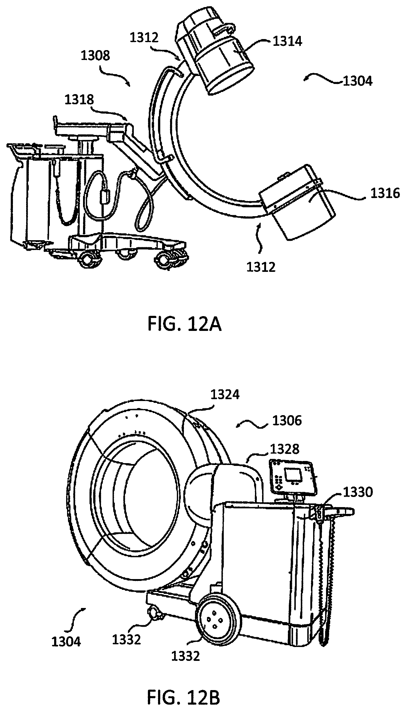
D00013

D00014

D00015

D00016
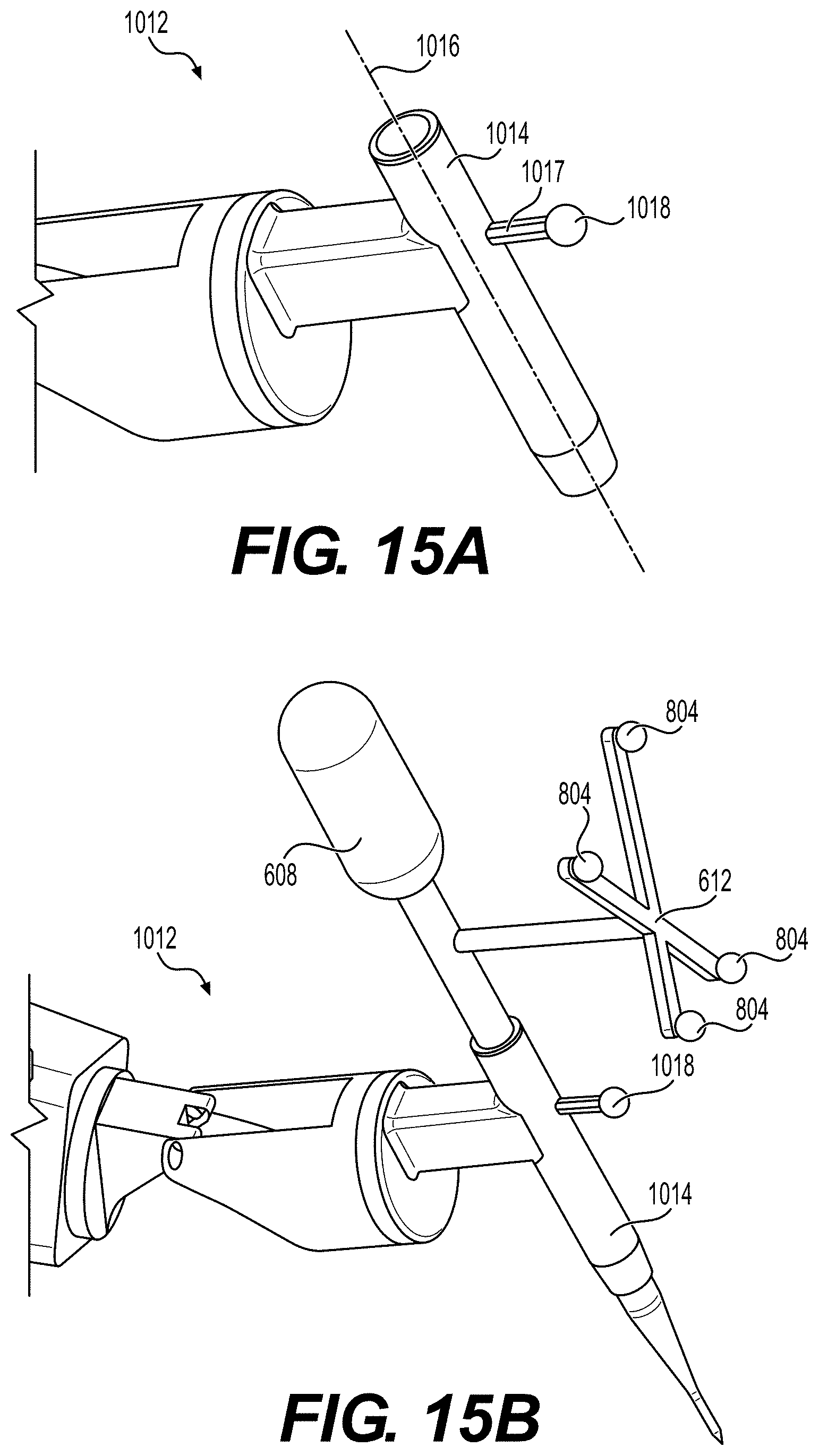
D00017
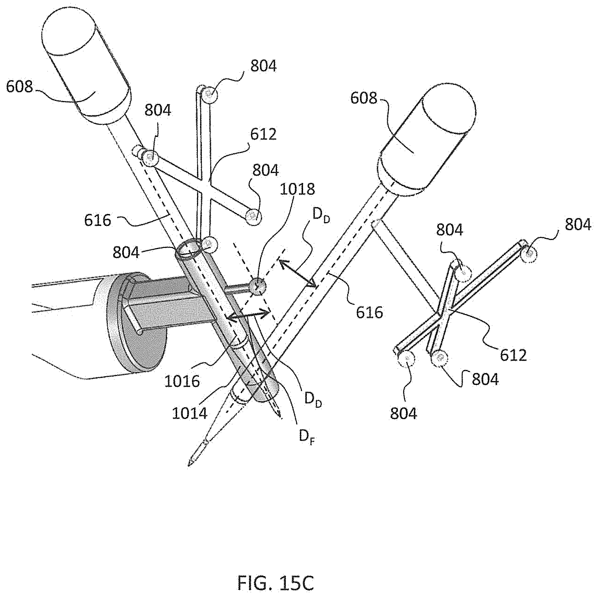
D00018
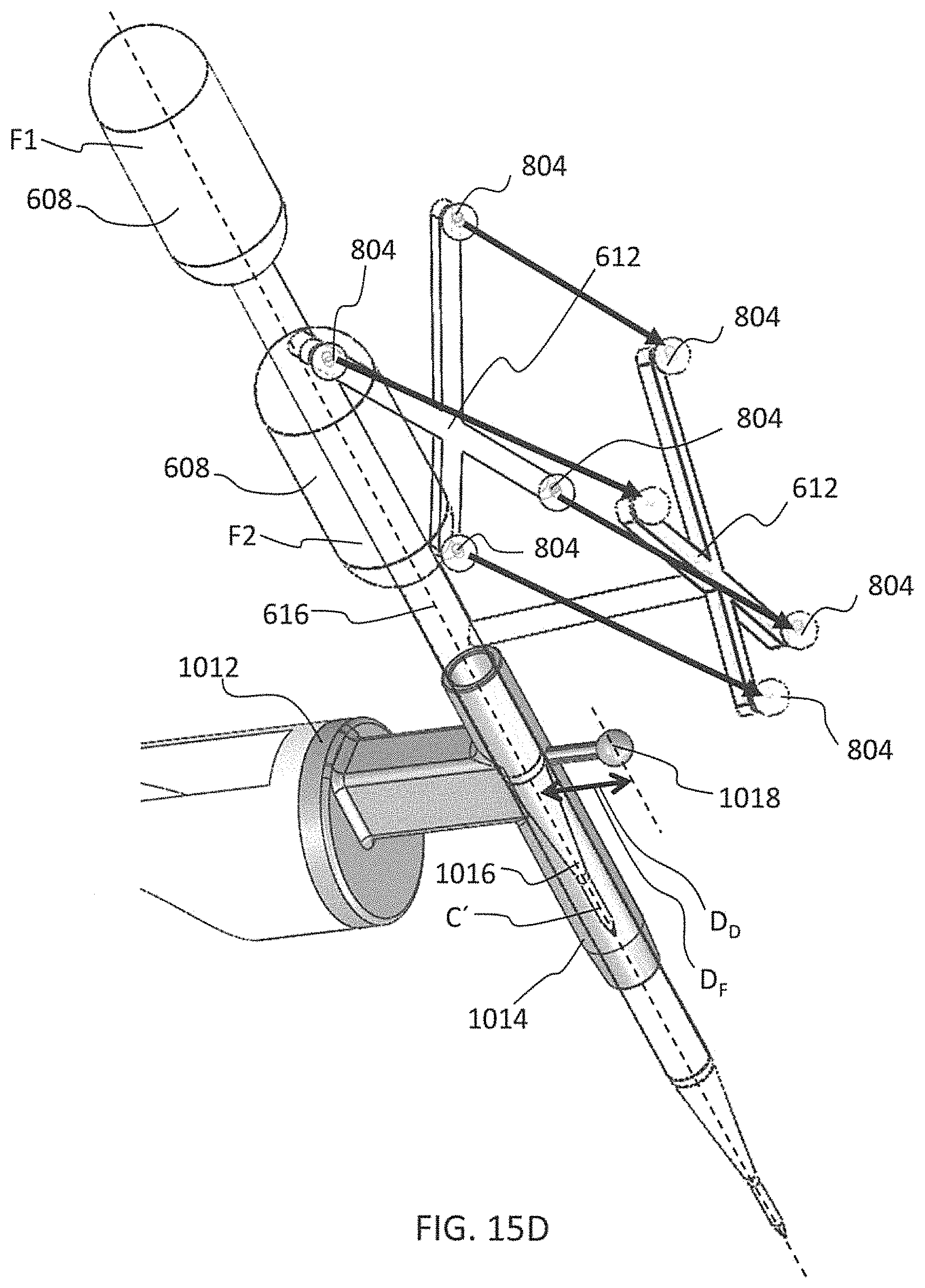
D00019
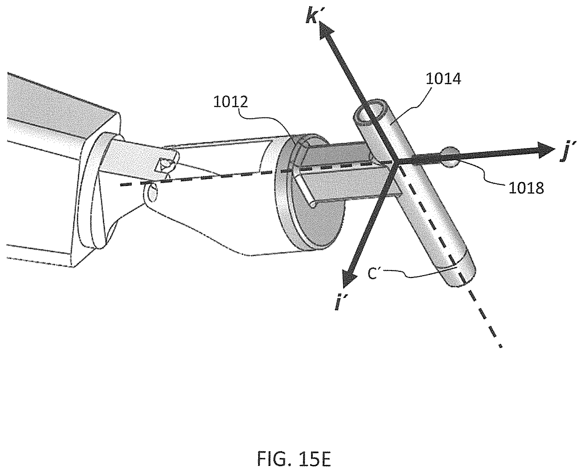
D00020

D00021

D00022

D00023
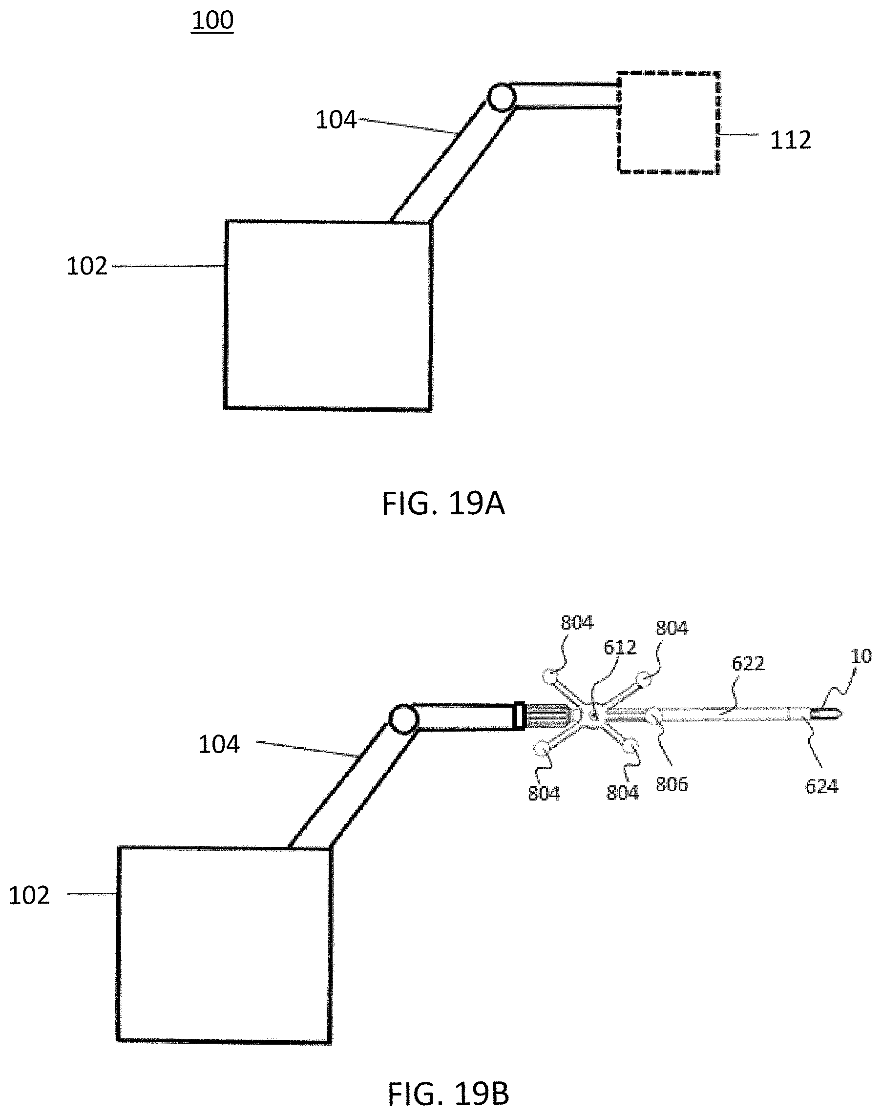
D00024

D00025

D00026
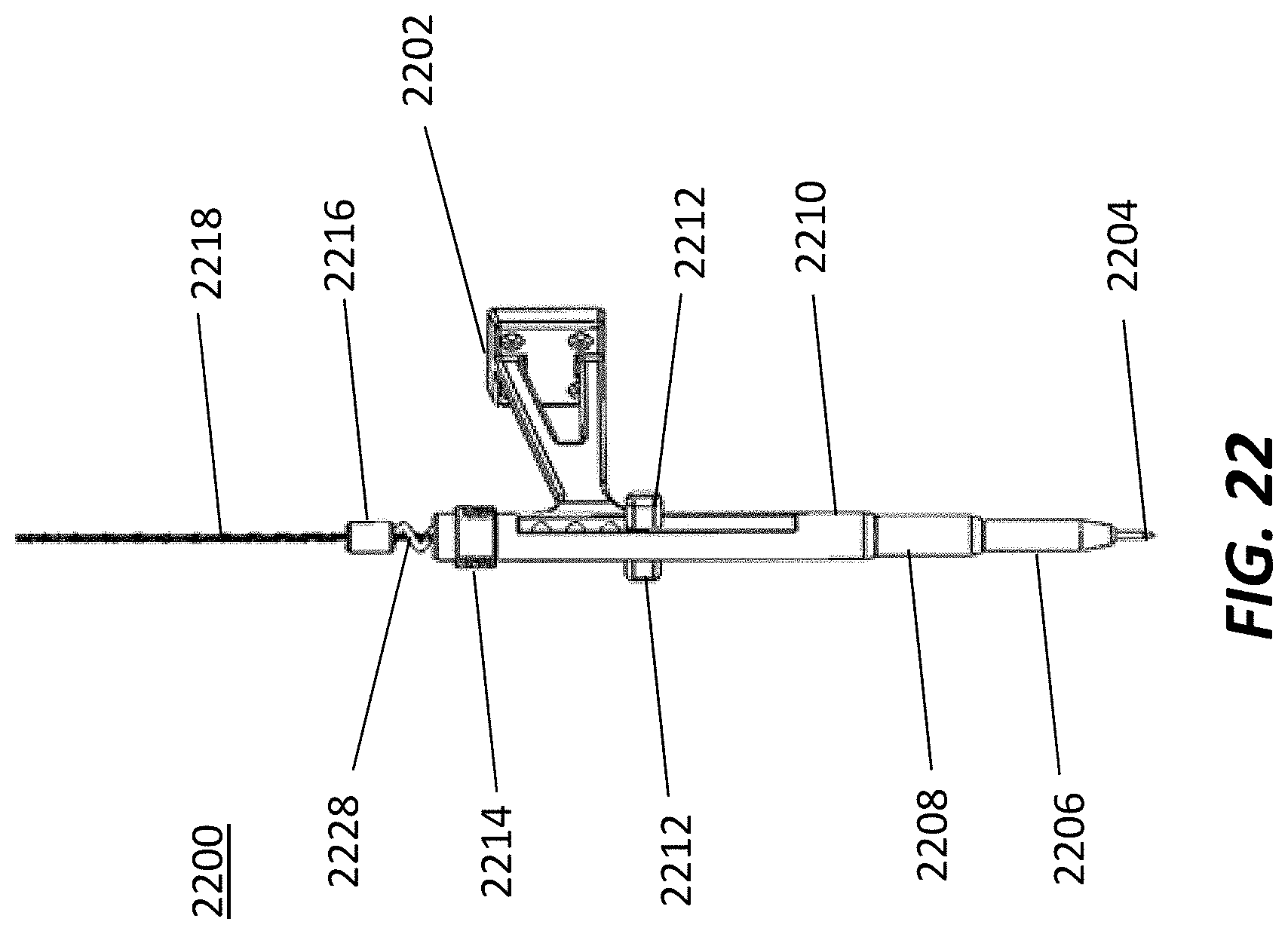
D00027
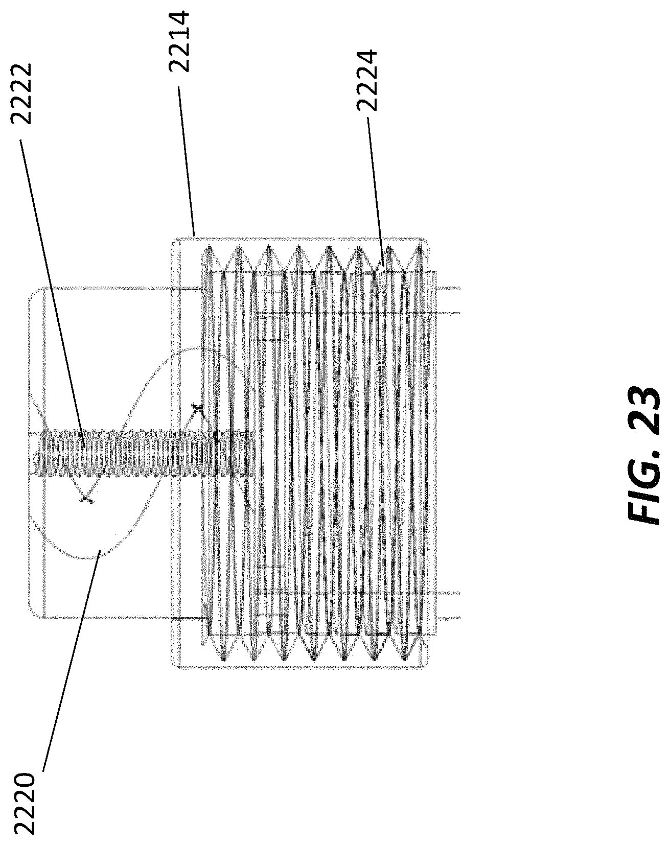
D00028
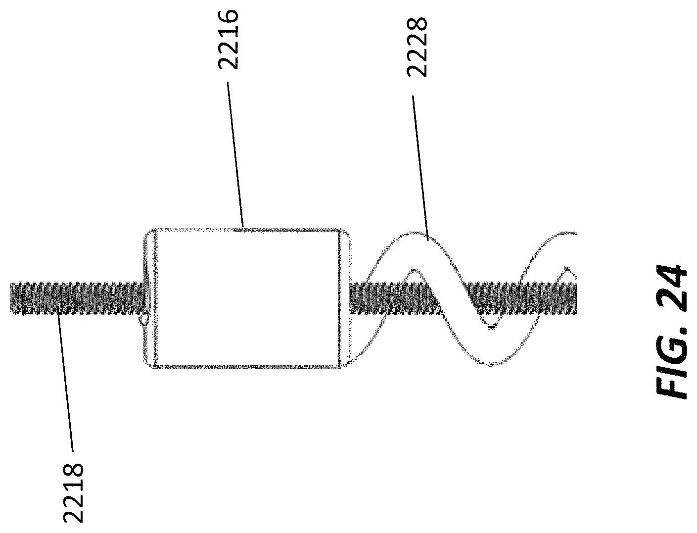
D00029

D00030

D00031

D00032

XML
uspto.report is an independent third-party trademark research tool that is not affiliated, endorsed, or sponsored by the United States Patent and Trademark Office (USPTO) or any other governmental organization. The information provided by uspto.report is based on publicly available data at the time of writing and is intended for informational purposes only.
While we strive to provide accurate and up-to-date information, we do not guarantee the accuracy, completeness, reliability, or suitability of the information displayed on this site. The use of this site is at your own risk. Any reliance you place on such information is therefore strictly at your own risk.
All official trademark data, including owner information, should be verified by visiting the official USPTO website at www.uspto.gov. This site is not intended to replace professional legal advice and should not be used as a substitute for consulting with a legal professional who is knowledgeable about trademark law.