Zoom lens and imaging apparatus
Kawana , et al. April 5, 2
U.S. patent number 11,294,158 [Application Number 16/828,641] was granted by the patent office on 2022-04-05 for zoom lens and imaging apparatus. This patent grant is currently assigned to FUJIFILM Corporation. The grantee listed for this patent is FUJIFILM Corporation. Invention is credited to Masanao Kawana, Yasutaka Shimada, Takuya Tanaka.


View All Diagrams
| United States Patent | 11,294,158 |
| Kawana , et al. | April 5, 2022 |
Zoom lens and imaging apparatus
Abstract
The zoom lens consists of, in order from an object side, a positive first lens group, a negative second lens group, a positive third lens group, a positive fourth lens group, and a positive fifth lens group. During zooming, the second lens group, the third lens group, and the fourth lens group move. The first lens group consists of, in order from an object side, a negative first a lens group, a positive first b lens group that moves during focusing, and a positive first c lens group. The second lens group includes one positive lens and one or more negative lenses successively in order from a most object side to an image side.
| Inventors: | Kawana; Masanao (Saitama, JP), Shimada; Yasutaka (Saitama, JP), Tanaka; Takuya (Saitama, JP), Tanaka; Takuya (Saitama, JP) | ||||||||||
|---|---|---|---|---|---|---|---|---|---|---|---|
| Applicant: |
|
||||||||||
| Assignee: | FUJIFILM Corporation (Tokyo,
JP) |
||||||||||
| Family ID: | 1000006218755 | ||||||||||
| Appl. No.: | 16/828,641 | ||||||||||
| Filed: | March 24, 2020 |
Prior Publication Data
| Document Identifier | Publication Date | |
|---|---|---|
| US 20200310091 A1 | Oct 1, 2020 | |
Foreign Application Priority Data
| Mar 26, 2019 [JP] | JP2019-059477 | |||
| Current U.S. Class: | 1/1 |
| Current CPC Class: | G02B 13/009 (20130101); G02B 15/20 (20130101); G02B 15/177 (20130101); G02B 9/60 (20130101); H04N 5/23296 (20130101); H04N 5/2254 (20130101); G02B 27/0025 (20130101) |
| Current International Class: | G02B 15/177 (20060101); G02B 13/00 (20060101); G02B 9/60 (20060101); G02B 15/20 (20060101); H04N 5/225 (20060101); H04N 5/232 (20060101); G02B 27/00 (20060101) |
| Field of Search: | ;359/680 |
References Cited [Referenced By]
U.S. Patent Documents
| 2005/0128604 | June 2005 | Kuba |
| 2013/0301141 | November 2013 | Ryu |
| 2015/0241673 | August 2015 | Nagatoshi |
| 2019/0025557 | January 2019 | Ota et al. |
| 2009-128491 | Jun 2009 | JP | |||
| 2015-230449 | Dec 2015 | JP | |||
| 2016-075828 | May 2016 | JP | |||
| 2018-072581 | May 2018 | JP | |||
| 2017/170047 | Oct 2017 | WO | |||
Other References
|
An Office Action mailed by the Japanese Patent Office dated Feb. 1, 2022, which corresponds to Japanese Patent Application No. 2019-059477 and is related to U.S. Appl. No. 16/828,641; with English language translation. cited by applicant. |
Primary Examiner: Greece; James R
Attorney, Agent or Firm: Studebaker & Brackett PC
Claims
What is claimed is:
1. A zoom lens consisting of, in order from an object side to an image side: a first lens group that has a positive refractive power; a second lens group that has a negative refractive power; a third lens group that has a positive refractive power; a fourth lens group that has a positive refractive power; and a fifth lens group that has a positive refractive power, wherein during zooming from a wide-angle end to a telephoto end, the first lens group and the fifth lens group remain stationary with respect to an image plane, the second lens group moves to an image side, and the third lens group and the fourth lens group move along an optical axis while changing a distance with each of adjacent lens groups, wherein the first lens group consists of, in order from an object side to an image side, a first a lens group that remains stationary with respect to an image plane during focusing and has a negative refractive power, a first b lens group that moves along an optical axis during focusing and has a positive refractive power, and a first c lens group that remains stationary with respect to an image plane during focusing and has a positive refractive power, and wherein the second lens group includes one positive lens and one or more negative lenses successively in order from a most object side to an image side.
2. The zoom lens according to claim 1, wherein among the negative lenses included in the second lens group, for the negative lens having a largest Abbe number based on a d line, assuming that an Abbe number based on a d line is .nu.n and a partial dispersion ratio between a g line and an F line is .theta.n, the following Conditional Expression (1) is satisfied, 0.01<.theta.n-(0.6483-0.001802.times..nu.n)<0.08 (1).
3. The zoom lens according to claim 1, wherein among the negative lenses included in the second lens group, the negative lens having a largest Abbe number based on a d line is disposed on an image side of the positive lens to be successive to the positive lens.
4. The zoom lens according to claim 1, wherein the positive lens and the negative lens disposed on an image side of the positive lens to be successive to the positive lens are cemented with each other to form a cemented lens.
5. The zoom lens according to claim 4, wherein assuming that an Abbe number of the positive lens of the cemented lens based on a d line of is .nu.p1, a partial dispersion ratio between a g line and an F line of the positive lens of the cemented lens is .theta.p1, an Abbe number of the negative lens of the cemented lens based on a d line is .nu.n1, and a partial dispersion ratio between a g line and an F line of the negative lens of the cemented lens is .theta.n1, the following Conditional Expressions (2) and (3) are satisfied, 35<.nu.n1-.nu.p1<70 (2) -0.09<.theta.n1-.theta.p1<-0.03 (3).
6. The zoom lens according to claim 1, wherein assuming that a focal length of the second lens group is f2 and a focal length of the positive lens is fp1, the following Conditional Expression (4) is satisfied, 0.3<|f2/fp1|<0.65 (4).
7. The zoom lens according to claim 1, wherein the second lens group consists of two or more positive lenses and three or more negative lenses.
8. The zoom lens according to claim 2, wherein the following Conditional Expression (1-1) is satisfied, 0.02<.theta.n-(0.6483-0.001802.times..nu.n)<0.07 (1-1).
9. The zoom lens according to claim 2, wherein the following Conditional Expression (1-2) is satisfied, 0.03<.theta.n-(0.6483-0.001802.times..nu.n)<0.07 (1-2).
10. The zoom lens according to claim 5, wherein the following Conditional Expression (2-1) is satisfied, 45<.nu.n1-.nu.p1<70 (2-1).
11. The zoom lens according to claim 5, wherein the following Conditional Expression (3-1) is satisfied, -0.08<.theta.n1-.theta.p1<-0.04 (3-1).
12. The zoom lens according to claim 6, wherein the following Conditional Expression (4-1) is satisfied, 0.4<|f2/fp1|<0.65 (4-1).
13. An imaging apparatus comprising the zoom lens according to claim 1.
Description
CROSS-REFERENCE TO RELATED APPLICATIONS
The present application claims priority under 35 U.S.C. .sctn. 119 to Japanese Patent Application No. 2019-059477, filed on Mar. 26, 2019. The above application is hereby expressly incorporated by reference, in its entirety, into the present application.
BACKGROUND OF THE INVENTION
1. Field of the Invention
The present disclosure relates to a zoom lens and an imaging apparatus.
2. Description of the Related Art
In the related art, a five-group lens system is known as a zoom lens used in a broadcast camera, a movie camera, a digital camera, and the like. For example, JP2015-230449A discloses a zoom lens which comprises, in order from an object side to an image side, a first lens group having a positive refractive power, a second lens group having a negative refractive power, a third lens group, a fourth lens group, and a fifth lens group having a positive refractive power, and in which the second lens group, the third lens group, and the fourth lens group move during zooming.
SUMMARY OF THE INVENTION
In recent years, a camera with a larger sensor size than the related art has been used in order to obtain a high image quality, and there is a need for a lens system having a large image circle for corresponding with such a camera. In addition, there is an increasing demand for image definition, and the lens system is required to have optical performance for corresponding with a pixel pitch equal to or less than the related art even in a case where the sensor size increases. On the other hand, in consideration of operation at an imaging site, there is a demand for avoiding a significant increase in size compared to a lens system that has been used in the related art.
The five-group lens system described in JP2015-230449A has a large lateral chromatic aberration and a small image circle. In a case where the five-group lens system described in JP2015-230449A is proportionally enlarged and thus realizes favorable optical performance so as to correspond with an image circle having a size desired in recent years, the overall length of the lens system becomes long.
The present disclosure has been made in view of the above circumstances, and an object thereof is to provide a zoom lens having a large image circle and favorable optical performance while suppressing a size of the entire system, and an imaging apparatus comprising the zoom lens.
A zoom lens according to an aspect of the present disclosure consists of, in order from an object side to an image side: a first lens group that has a positive refractive power; a second lens group that has a negative refractive power; a third lens group that has a positive refractive power; a fourth lens group that has a positive refractive power; and a fifth lens group that has a positive refractive power, wherein during zooming from a wide-angle end to a telephoto end, the first lens group and the fifth lens group remain stationary with respect to an image plane, the second lens group moves to an image side, and the third lens group and the fourth lens group move along an optical axis while changing a distance with each of adjacent lens groups, wherein the first lens group consists of, in order from an object side to an image side, a first a lens group that remains stationary with respect to an image plane during focusing and has a negative refractive power, a first b lens group that moves along an optical axis during focusing and has a positive refractive power, and a first c lens group that remains stationary with respect to an image plane during focusing and has a positive refractive power, and wherein the second lens group includes one positive lens and one or more negative lenses successively in order from a most object side to an image side.
Among the negative lenses included in the second lens group of the zoom lens of the above described aspect, for the negative lens having a largest Abbe number based on a d line, assuming that an Abbe number based on a d line is .nu.n and a partial dispersion ratio between a g line and an F line is .theta.n, it is preferable that the following Conditional Expression (1) is satisfied, it is more preferable that the following Conditional Expression (1-1) is satisfied, and it is still more preferable that the following Conditional Expression (1-2) is satisfied. 0.01<.theta.n-(0.6483-0.001802.times..nu.n)<0.08 (1) 0.02<.theta.n-(0.6483-0.001802.times..nu.n)<0.07 (1-1) 0.03<.theta.n-(0.6483-0.001802.times..nu.n)<0.07 (1-2)
It is preferable that among the negative lenses included in the second lens group of the zoom lens of the above described aspect, the negative lens having a largest Abbe number based on a d line is disposed on an image side of the positive lens to be successive to the positive lens.
In the zoom lens of the above described aspect, it is preferable that the positive lens and the negative lens disposed on an image side of the positive lens to be successive to the positive lens are cemented with each other to form a cemented lens.
In a case where the zoom lens of the above described aspect has the cemented lens, assuming that an Abbe number of the positive lens of the cemented lens based on a d line of is .nu.p1, a partial dispersion ratio between a g line and an F line of the positive lens of the cemented lens is .theta.p1, an Abbe number of the negative lens of the cemented lens based on a d line is .nu.n1, and a partial dispersion ratio between a g line and an F line of the negative lens of the cemented lens is .theta.n1, it is preferable that the following Conditional Expressions (2) and (3) are satisfied. Further, in addition to satisfying Conditional Expressions (2) and (3), it is more preferable that at least one of the following Conditional Expression (2-1) or (3-1) is satisfied. 35<.nu.n1-.nu.p1<70 (2) -0.09<.theta.n1-.theta.p1<-0.03 (3) 45<.nu.n1-.nu.p1<70 (2-1) -0.08<.theta.n1-.theta.p1<-0.04 (3-1)
In the zoom lens of the above described aspect, assuming that a focal length of the second lens group is f2 and a focal length of the positive lens is fp1, it is preferable to satisfy the following Conditional Expression (4), and it is more preferable to satisfy the Conditional Expression (4-1). 0.3<|f2/fp1|<0.65 (4) 0.4<|f2/fp1|<0.65 (4-1)
It is preferable that the second lens group of the zoom lens of the above described aspect consists of two or more positive lenses and three or more negative lenses.
An imaging apparatus according to another aspect of the present disclosure comprises the zoom lens of the above described aspect of the present disclosure.
In the present specification, it should be noted that the terms "consisting of .about." and "consists of .about." mean that the lens may include not only the above-mentioned elements but also lenses substantially having no refractive powers, optical elements, which are not lenses, such as a stop, a filter, and a cover glass, and mechanism parts such as a lens flange, a lens barrel, an imaging element, and a camera shaking correction mechanism.
In addition, the term ".about. group that has a positive refractive power" in the present specification means that the group has a positive refractive power as a whole. Likewise, the term ".about. group having a negative refractive power" means that the group has a negative refractive power as a whole. The term "a lens having a positive refractive power" and the term "a positive lens" are synonymous. The term "a lens having a negative refractive power" and the term "a negative lens" are synonymous. The "lens group" is not limited to a configuration using a plurality of lenses, and may consist of only one lens.
The sign of the refractive power and the surface shape of a lens including an aspheric surface are considered in terms of the paraxial region unless otherwise noted. A compound aspheric lens (a lens which is integrally composed of a spherical lens and a film having an aspheric shape formed on the spherical lens, and functions as one aspheric lens as a whole) is not considered as a cemented lens, and is treated as a single lens.
The "focal length" used in a conditional expression is a paraxial focal length. The value used in a conditional expression is a value in the case of using a d line as a reference in a state of being focused on an object at infinity, in addition to a partial dispersion ratio. Assuming that refractive indexes of a lens with respect to a g line, an F line, and a C line are Ng, NF, and NC, respectively, a partial dispersion ratio .theta.gF between the g line and the F line of the lens is defined as .theta.gF=(Ng-NF)/(NF-NC). The "d line", "C line", "F line", and "g line" described in this specification are bright lines, the wavelength of the d line is 587.56 nm (nanometers), the wavelength of the C line is 656.27 nm (nanometers), the wavelength of the F line is 486.13 nm (nanometers), and the wavelength of the g line is 435.84 nm (nanometers).
According to the present disclosure, it is possible to provide a zoom lens having a large image circle and favorable optical performance while suppressing a size of the entire system, and an imaging apparatus comprising the zoom lens.
BRIEF DESCRIPTION OF THE DRAWINGS
FIG. 1 is a diagram showing a cross-sectional view of a configuration of a zoom lens according to an embodiment of the present disclosure and a movement locus thereof, corresponding to a zoom lens of Example 1 of the present disclosure.
FIG. 2 is a cross-sectional view showing configurations and rays of the zoom lens shown in FIG. 1 in each zoom state.
FIG. 3 shows respective aberration diagrams of the zoom lens according to Example 1 of the present disclosure.
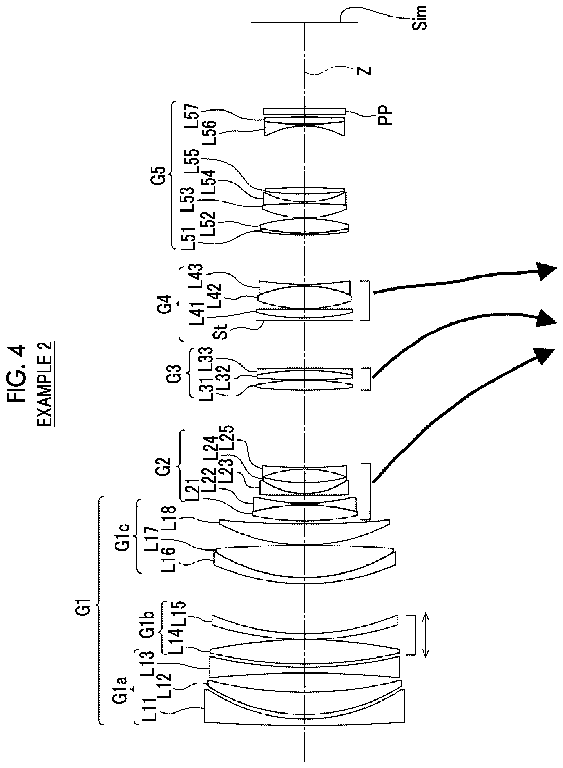
FIG. 4 is a diagram showing a cross-sectional view of a configuration of a zoom lens according to Example 2 of the present disclosure and a movement locus thereof.
FIG. 5 shows respective aberration diagrams of the zoom lens according to Example 2 of the present disclosure.
FIG. 6 is a diagram showing a cross-sectional view of a configuration of a zoom lens according to Example 3 of the present disclosure and a movement locus thereof.
FIG. 7 shows respective aberration diagrams of the zoom lens according to Example 3 of the present disclosure.
FIG. 8 is a diagram showing a cross-sectional view of a configuration of a zoom lens according to Example 4 of the present disclosure and a movement locus thereof.
FIG. 9 shows respective aberration diagrams of the zoom lens according to Example 4 of the present disclosure.
FIG. 10 is a diagram showing a cross-sectional view of a configuration of a zoom lens according to Example 5 of the present disclosure and a movement locus thereof.
FIG. 11 shows respective aberration diagrams of the zoom lens according to Example 5 of the present disclosure.
FIG. 12 is a schematic configuration diagram of an imaging apparatus according to an embodiment of the present disclosure.
DESCRIPTION OF THE PREFERRED EMBODIMENTS
Hereinafter, embodiments of a zoom lens of the present disclosure will be described in detail with reference to the drawings. FIG. 1 is a diagram showing a cross-sectional view of a configuration and a movement locus of a zoom lens according to an embodiment of the present disclosure at a wide-angle end. FIG. 2 is a cross-sectional view showing configurations and rays of the zoom lens in each zoom state. The example shown in FIGS. 1 and 2 correspond to a zoom lens of Example 1 to be described later. FIGS. 1 and 2 show states of being focused on an object at infinity, a left side thereof is an object side, and a right side thereof is an image side. In FIG. 2, an upper part labeled by "WIDE" shows a wide-angle end state, and a lower part labeled by "TELE" shows a telephoto end state. FIG. 2 shows rays including on-axis rays wa and rays with the maximum angle of view wb in a wide-angle end state, and on-axis rays to and rays with the maximum angle of view tb in a telephoto end state. Hereinafter, description will be given mainly with reference to FIG. 1.
FIG. 1 shows an example in which, assuming that a zoom lens is applied to an imaging apparatus, an optical member PP having a parallel plate shape is disposed between the zoom lens and an image plane Sim. The optical member PP is a member assumed to include various filters, a cover glass, and/or the like. The various filters include, for example, a low pass filter, an infrared cut filter, a filter that cuts a specific wavelength region, and the like. The optical member PP has no refractive power, and in the present disclosure, the optical member PP may be omitted.
The zoom lens of the present disclosure consists of, in order from an object side to an image side along an optical axis Z, a first lens group G1 that has a positive refractive power, a second lens group G2 that has a negative refractive power, a third lens group G3 that has a positive refractive power, a fourth lens group G4 that has a positive refractive power, and a fifth lens group G5 that has a positive refractive power. By configuring a most-object-side first lens group G1 with a positive lens group, an overall length of a lens system can be shortened, which is advantageous for downsizing. In addition, by configuring a most-image-side fifth lens group G5 with a positive lens group, it is possible to suppress an increase in an incidence angle of a principal ray of an off-axis ray to an image plane Sim, thereby to suppress shading.
In the example shown in FIG. 1, the first lens group G1 consists of eight lenses L11 to L18 in order from an object side to an image side, the second lens group G2 consists of five lenses L21 to L25 in order from an object side to an image side, the third lens group G3 consists of three lenses L31 to L33 in order from an object side to an image side, the fourth lens group G4 consists of an aperture stop St and three lenses L41 to L43 in order from an object side to an image side, and the fifth lens group G5 consists of seven lenses L51 and L57 in order from an object side to an image side. Meanwhile, in the zoom lens of the present disclosure, the number of lenses composing each lens group may be different from the number in the example shown in FIG. 1. In addition, the aperture stop St shown in FIG. 1 does not show its shape, but shows its position in a direction of an optical axis.
In the zoom lens of the present disclosure, it is configured such that during zooming from a wide-angle end to a telephoto end, the first lens group G1 and the fifth lens group G5 remain stationary with respect to an image plane Sim, the second lens group G2 always moves to an image side, and the third lens group G3 and the fourth lens group G4 move along an optical axis Z while changing a distance with each of adjacent lens groups. In FIG. 1, under the second lens group G2, the third lens group G3, and the fourth lens group G4, movement loci of the respective lens groups during zooming from a wide-angle end to a telephoto end are schematically indicated by arrows. It is possible that main zooming is performed by moving the second lens group G2 having a negative refractive power, and fluctuation in an image plane position due to zooming is corrected by moving the third lens group G3 and the fourth lens group G4. Since the third lens group G3 and the fourth lens group G4 move relatively during zooming, it is easy to favorably suppress fluctuation in a field curvature during zooming and fluctuation in a spherical aberration during zooming. In addition, the first lens group G1 and the fifth lens group G5 are configured to remain stationary during zooming. In such a configuration, a distance from a most-object-side lens surface to a most-image-side lens surface does not change during zooming, and it is possible to reduce fluctuation in barycenter of a lens system. Thus, it is possible to improve the convenience at the time of imaging.
The first lens group G1 consists of, in order from an object side to an image side, a first a lens group G1a that remains stationary with respect to an image plane Sim during focusing and has a negative refractive power, a first b lens group G1b that moves along an optical axis Z during focusing and has a positive refractive power, and a first c lens group G1c that remains stationary with respect to an image plane Sim during focusing and has a positive refractive power. With such a configuration, it is easy to reduce a spherical aberration and an on-axis chromatic aberration that occur during focusing. A horizontal double-headed arrow noted below the first b lens group G1b in FIG. 1 indicates that the first b lens group G1b is a focus lens group that moves during focusing.
It is preferable that the first b lens group G1b consists of, in order from an object side to an image side, a positive lens having a convex surface facing an object side and a negative meniscus lens having a convex surface facing an object side. In such a case, it is easy to suppress fluctuation in an off-axis aberration during focusing.
As an example, in the example shown in FIG. 1, the first a lens group G1a consists of three lenses L11 to L13 in order from an object side to an image side, the first b lens group G1b consists of two lenses L14 and L15 in order from an object side to an image side, and the first c lens group G1c consists of three lenses L16 to L18 in order from an object side to an image side. Meanwhile, in the zoom lens of the present disclosure, the number of lenses composing each lens group may be different from the number in the example shown in FIG. 1.
The second lens group G2 is configured to include one positive lens and one or more negative lenses successively in order from a most object side to an image side. By disposing the positive lens on a most object side of the second lens group G2, the height of an off-axis ray in the second lens group G2 can be reduced and the occurrence of lateral chromatic aberration can be suppressed. By disposing the negative lenses to be successive to a most-object-side positive lens of the second lens group G2, it is advantageous for correcting the lateral chromatic aberration.
Assuming that among the negative lenses included in the second lens group G2, for a negative lens having a largest Abbe number based on a d line, an Abbe number based on a d line is .nu.n and a partial dispersion ratio between a g line and an F line is .theta.n, it is preferable that the following Conditional Expression (1) is satisfied. By not allowing the result of Conditional Expression (1) to be equal to or less than a lower limit, it is advantageous for correcting a secondary chromatic aberration. By not allowing the result of Conditional Expression (1) to be equal to or more than an upper limit, it is possible to select a material having an appropriate Abbe number and it is easy to correct a primary chromatic aberration. Further, in a case of a configuration in which the following Conditional Expression (1-1) is satisfied, it is possible to obtain more favorable characteristics, and in a case of a configuration in which the following Conditional Expression (1-2) is satisfied, it is possible to obtain still more favorable characteristics. 0.01<.theta.n-(0.6483-0.001802.times..nu.n)<0.08 (1) 0.02<.theta.n-(0.6483-0.001802.times..nu.n)<0.07 (1-1) 0.03<.theta.n-(0.6483-0.001802.times..nu.n)<0.07 (1-2)
It is preferable that among the negative lenses included in the second lens group G2, a negative lens having a largest Abbe number based on a d line is disposed on an image side of a most-object-side positive lens of the second lens group G2 to be successive to the positive lens. That is, it is preferable that among the negative lenses included in the second lens group G2, a negative lens having a largest Abbe number based on a d line is disposed on a most object side among the negative lenses of the second lens group G2. In such a case, it is easy to suppress the occurrence of a lateral chromatic aberration on the wide angle side.
It is preferable that the most-object-side positive lens of the second lens group G2 and the negative lenses disposed on an image side of the positive lens to be successive to the positive lens are cemented with each other to form a cemented lens. By disposing the cemented lens formed by cementing the positive lens and the negative lens in order from an object side on a most object side of the second lens group G2, it is easy to favorably correct a lateral chromatic aberration while suppressing a thickness of the second lens group G2 on the optical axis.
In a configuration in which the cemented lens is disposed on a most object side of the second lens group G2, assuming that an Abbe number of the positive lens of the cemented lens based on a d line of is .nu.p1, a partial dispersion ratio between a g line and an F line of the positive lens of the cemented lens is .theta.p1, an Abbe number of the negative lens of the cemented lens based on a d line is .nu.n1, and a partial dispersion ratio between a g line and an F line of the negative lens of the cemented lens is .theta.n1, it is preferable that the following Conditional Expressions (2) and (3) are satisfied. By satisfying both Conditional Expressions (2) and (3), it is easy to favorably correct a primary chromatic aberration and a secondary chromatic aberration on a telephoto side. Further, in addition to satisfying Conditional Expressions (2) and (3), in a case of a configuration in which at least one of the following Conditional Expression (2-1) or (3-1) is satisfied, it is possible to obtain more favorable characteristics. 35<.nu.n1-.nu.p1<70 (2) -0.09<.theta.n1-.theta.p1<-0.03 (3) 45<.nu.n1-.nu.p1<70 (2-1) -0.08<.theta.n1-.theta.p1<-0.04 (3-1)
In addition, assuming that a focal length of the second lens group G2 is f2 and a focal length of a most-object-side positive lens of the second lens group G2 is fp1, it is preferable that the following Conditional Expression (4) is satisfied. By not allowing the result of Conditional Expression (4) to be equal to or less than a lower limit, a height of an off-axis ray in the second lens group G2 is not increased, and thus it is easy to reduce a lateral chromatic aberration. By not allowing the result of Conditional Expression (4) to be equal to or more than an upper limit, a refractive power of a most-object-side positive lens of the second lens group G2 is allowed to be prevented from becoming excessively strong. As a result, it is easy to correct various aberrations. In addition, in a case of a configuration in which the following Conditional Expression (4-1) is satisfied, it is possible to obtain more favorable characteristics. 0.3<|f2/fp1|<0.65 (4) 0.4<|f2/fp1|<0.65 (4-1)
The second lens group G2 may be configured to consist of two or more positive lenses and three or more negative lenses. In such a case, by dividing a negative refractive power of the second lens group G2 into a plurality of lenses, it is possible to suppress the occurrence of an aberration, to correct a chromatic aberration occurred in each negative lens by the positive lens, and to suppress aberration fluctuation during zooming.
For example, the second lens group G2 can be configured to consist of, in order from an object side, a first cemented lens in which a positive lens and a negative lens are cemented in order from an object side, a second cemented lens in which a negative lens and a positive lens are cemented in order from an object side, and a negative lens. As an example, in the example shown in FIG. 1, the first cemented lens consists of a biconvex lens and a biconcave lens, the second cemented lens consists of a negative lens having a concave surface facing an image side and a positive meniscus lens having a convex surface facing an object side, and a most-image-side negative lens of the second lens group consists of a biconcave lens.
In addition, in the example shown in FIG. 1, the aperture stop St is disposed in the fourth lens group G4, and a distance between the fourth lens group G4 and the fifth lens group G5 at a wide-angle end is longer than a distance between the fourth lens group G4 and the fifth lens group G5 at a telephoto end. With such a configuration, it is possible to position a position of the aperture stop St at a wide-angle end closer to the object side than a position of the aperture stop St at a telephoto end, and thus it is possible to position an entrance pupil position at a wide-angle end closer to an object side than an entrance pupil position at a telephoto end. Accordingly, it is easy to suppress increase in an outer diameter of the first lens group G1 while inhibiting an overall length of the lens system from becoming long.
The above-mentioned preferred configurations and available configurations may be optional combinations, and it is preferable to selectively adopt the configurations in accordance with required specification. According to technology of the present disclosure, it is possible to realize a zoom lens having a large image circle and favorable optical performance while suppressing a size of the entire system. Further, "an image circle is large" means that a diameter of an image circle is larger than 43.2.
Next, numerical examples of the zoom lens of the present disclosure will be described.
Example 1
FIG. 1 shows a configuration and movement locus of a zoom lens of Example 1, and an illustration method and a configuration thereof are as described above. Therefore, repeated description is partially omitted herein. The zoom lens of Example 1 consists of, in order from an object side to an image side, a first lens group G1 that has a positive refractive power, a second lens group G2 that has a negative refractive power, a third lens group G3 that has a positive refractive power, a fourth lens group G4 that has a positive refractive power, and a fifth lens group G5 that has a positive refractive power. During zooming, the first lens group G1 and the fifth lens group G5 remain stationary with respect to an image plane Sim, and the second lens group G2, the third lens group G3, and the fourth lens group G4 move along an optical axis Z while changing a distance with each of adjacent lens groups. The first lens group G1 consists of, in order from an object side to an image side, a first a lens group G1a having a negative refractive power, a first b lens group G1b having a positive refractive power, and a first c lens group G1c having a positive refractive power. During focusing, only the first b lens group G1b moves along an optical axis Z, and all other lens groups remain stationary with respect to an image plane Sim. The first a lens group G1a consists of three lenses L11 to L13 in order from an object side to an image side, the first b lens group G1b consists of two lenses L14 and L15 in order from an object side to an image side, the first c lens group G1c consists of three lenses L16 to L18 in order from an object side to an image side, the second lens group G2 consists of five lenses L21 to L25 in order from an object side to an image side, the third lens group G3 consists of three lenses L31 to L33 in order from an object side to an image side, the fourth lens group G4 consists of an aperture stop St and three lenses L41 to L43 in order from an object side to an image side, and the fifth lens group G5 consists of seven lenses L51 and L57 in order from an object side to an image side. An outline of the zoom lens of Example 1 has been described above.
Regarding the zoom lens of Example 1, Tables 1A and 1B show basic lens data thereof, Table 2 shows specification and variable surface distances thereof, and Table 3 shows aspheric coefficients thereof. Here, the basic lens data is displayed to be divided into two tables of Table 1A and Table 1B in order to prevent one table from becoming long. Table 1A shows the first lens group G1, the second lens group G2, and the third lens group G3, and Table 1B shows the fourth lens group G4, the fifth lens group G5, and the optical member PP. Tables 1A, 1B, and 2 show data in a state of being focused on an object at infinity.
In Tables 1A and 1B, the column of Sn shows a surface number. A most-object-side surface is the first surface, and the surface numbers increase one by one toward an image side. The column of R shows radii of curvature of the respective surfaces. The column of D shows surface distances on an optical axis between the respective surfaces and the surfaces adjacent to an image side. The column of Nd shows a refractive index of each constituent element with respect to the d line, the column of .nu.d shows an Abbe number of each constituent element based on the d line, and the column of .theta.gF shows a partial dispersion ratio between the g line and the F line of each constituent element.
In Tables 1A and 1B, a sign of a radius of curvature of a surface having a convex surface facing an object side is positive and a sign of a radius of curvature of a surface having a convex surface facing an image side is negative. Table 1B also shows the aperture stop St and the optical member PP. In Table 1B, in the column of a surface number of a surface corresponding to the aperture stop St, the surface number and a term of (St) are noted. In Tables 1A and 1B, the variable surface distances during zooming are referenced by reference signs DD[ ], and are written into columns of D, where object side surface numbers of distances are noted in [ ].
In Table 2, values of a zoom ratio Zr, a focal length f, an F number FNo., a maximum total angle of view 2.omega., a maximum image height IH, and a variable surface distance during zooming are shown based on the d line. (.degree.) in the column of 2.omega. indicates that a unit thereof is a degree. In Table 2, values in a wide-angle end state and a telephoto end state are respectively shown in the columns labeled by WIDE and TELE.
In the basic lens data, a surface number of an aspheric surface is marked with *, and the numerical value of a paraxial radius of curvature is described in the column of a radius of curvature of the aspheric surface. In Table 3, a surface number of an aspheric surface is shown in the column of Sn, and the numerical value of the aspheric coefficient for each aspheric surface is shown in the columns of KA and Am (m is an integer of 3 or more and varies depending on the surface). The numerical value "E.+-.n" (n: integer) of the aspheric coefficient in Table 3 means ".times.10.sup..+-.n". KA and Am are aspheric coefficients in an aspheric expression represented by the following expression. Zd=C.times.h.sup.2/{1+(1-KA.times.C.sup.2.times.h.sup.2).sup.1/2}+.SIGMA.- Am.times.h.sup.m Where, Zd: aspheric depth (a length of a perpendicular line drawn from a point on an aspheric surface of a height h to a plane perpendicular to an optical axis in contact with an aspheric vertex) h: height (a distance from an optical axis to a lens surface) C: reciprocal of paraxial radius of curvature KA, Am: aspheric coefficient, and .SIGMA. in the aspheric expression means the sum of m.
In data of each table, a degree is used as a unit of an angle, and mm (millimeter) is used as a unit of a length, but appropriate different units may be used since the optical system can be used even in a case where the system is enlarged or reduced in proportion. Further, each of the following tables shows numerical values rounded off to predetermined decimal places.
TABLE-US-00001 TABLE 1A Example 1 Sn R D Nd .nu.d .theta.gF 1 635.85687 2.900 1.48749 70.24 0.53007 2 84.82438 1.793 *3 87.86309 8.493 1.85000 27.03 0.60935 4 216.23584 5.966 5 -483.34168 2.500 1.90265 35.77 0.58156 6 165.52407 2.946 7 180.38340 10.407 1.53775 74.70 0.53936 8 -198.00903 0.120 9 143.26123 2.460 1.80518 25.46 0.61572 10 104.68399 23.548 11 103.49980 2.500 1.84666 23.80 0.62155 12 78.30285 12.975 1.43700 95.10 0.53364 13 -945.64008 0.120 *14 78.80183 9.269 1.53775 74.70 0.53936 15 404.64010 DD[15] 16 84.74415 7.007 1.71736 29.52 0.60483 17 -105.29570 0.910 1.43700 95.10 0.53364 18 64.21500 4.216 19 -696.01274 0.810 1.80400 46.53 0.55775 20 37.26187 3.820 1.80518 25.46 0.61572 21 73.04376 5.685 22 -56.97749 1.000 1.90043 37.37 0.57668 23 191.39800 DD[23] 24 219.72433 3.895 1.84850 43.79 0.56197 25 -133.61317 0.120 26 314.29080 4.197 1.53775 74.70 0.53936 27 -100.17207 1.310 1.84661 23.88 0.62072 28 -450.21790 DD[28]
TABLE-US-00002 TABLE 1B Example 1 Sn R D Nd .nu.d .theta.gF 29(St) .infin. 1.264 30 101.75400 3.474 1.56883 56.04 0.54853 31 -3223.37330 0.120 32 59.24167 9.429 1.53775 74.70 0.53936 33 -54.26328 0.800 1.90043 37.37 0.57668 34 122.12441 DD[34] 35 112.18810 1.200 1.59282 68.62 0.54414 36 72.07593 7.336 1.59270 35.31 0.59336 37 -69.30383 0.120 38 43.98928 7.187 1.53775 74.70 0.53936 39 -681.51453 0.700 1.87070 40.73 0.56825 40 39.63685 3.045 41 142.09020 3.566 1.51860 69.89 0.53184 42 -190.64442 23.636 43 -34.25938 0.810 1.55032 75.50 0.54001 44 286.70593 3.044 1.84661 23.88 0.62072 45 -119.04366 1.000 46 .infin. 2.620 1.51680 64.20 0.53430 47 .infin. 39.843
TABLE-US-00003 TABLE 2 Example 1 WIDE TELE Zr 1.0 3.0 f 80.038 241.714 FNo. 2.76 3.36 2.omega.(.degree.) 32.2 10.6 IH 23.15 23.15 DD[15] 2.787 59.245 DD[23] 35.458 1.115 DD[28] 19.852 7.867 DD[34] 17.889 7.759
TABLE-US-00004 TABLE 3 Example 1 Sn 3 14 KA 1.0000000E+00 1.0000000E+00 A4 6.2324088E-08 -8.9421762E-08 A6 -6.8897292E-12 1.9234241E-12 A8 8.7272717E-15 -1.1060557E-14 A10 -3.7757721E-18 4.2371881E-18 A12 6.5123320E-22 -8.9972553E-22
FIG. 3 shows an aberration diagram in a state of being focused on an object at infinity through the zoom lens of Example 1. In FIG. 3, in order from a left side, a spherical aberration, an astigmatism, a distortion, and a lateral chromatic aberration are shown. In FIG. 3, an upper part labeled by "WIDE" shows an aberration in a wide-angle end state, and a lower part labeled by "TELE" shows an aberration in a telephoto end state. In the spherical aberration diagram, aberrations at the d line, the C line, the F line, and the g line are indicated by the solid line, the long dashed line, the short dashed line, and the chain line, respectively. In the astigmatism diagram, an aberration in the sagittal direction at the d line is indicated by the solid line, and an aberration in the tangential direction at the d line is indicated by the short dashed line. In the distortion diagram, an aberration at the d line is indicated by the solid line. In the lateral chromatic aberration diagram, aberrations at the C line, the F line, and the g line are respectively indicated by the long dashed line, the short dashed line, and the chain line. In the spherical aberration diagram, FNo. indicates an F number. In other aberration diagrams, .omega. indicates a half angle of view.
Symbols, meanings, description methods, and illustration methods of the respective data pieces according to Example 1 are the same as those in the following examples unless otherwise noted. Therefore, in the following description, repeated description will be omitted.
Example 2
FIG. 4 shows a configuration and a movement locus of the zoom lens of Example 2. The zoom lens of Example 2 has the same configuration as the outline of the zoom lens of Example 1. Regarding the zoom lens of Example 2, Tables 4A and 4B show basic lens data thereof, Table 5 shows specification and variable surface distances thereof, Table 6 shows aspheric coefficients thereof, and FIG. 5 shows aberration diagrams thereof.
TABLE-US-00005 TABLE 4A Example 2 Sn R D Nd .nu.d .theta.gF 1 635.15805 2.900 1.48749 70.24 0.53007 2 76.88429 1.927 *3 79.87321 9.658 1.85000 27.03 0.60935 4 173.99971 8.207 5 -424.51509 2.500 1.90265 35.77 0.58156 6 184.06981 1.500 7 181.69597 10.492 1.53775 74.70 0.53936 8 -202.61114 0.120 9 135.41034 2.460 1.80518 25.46 0.61572 10 105.19566 21.710 11 103.51244 2.500 1.84666 23.80 0.62155 12 74.84931 13.887 1.43700 95.10 0.53364 13 -547.07592 0.120 *14 79.00358 9.160 1.53775 74.70 0.53936 15 411.30161 DD[15] 16 113.43496 6.819 1.71736 29.52 0.60483 17 -91.18431 0.810 1.43700 95.10 0.53364 18 85.48627 3.541 19 2230.66576 0.710 1.80400 46.53 0.55775 20 32.68367 4.613 1.80518 25.46 0.61572 21 69.27881 5.885 22 -52.73542 0.700 1.90043 37.37 0.57668 23 202.51249 DD[23] 24 208.26640 4.231 1.84850 43.79 0.56197 25 -116.75928 0.120 26 265.79196 4.225 1.53775 74.70 0.53936 27 -105.50772 0.800 1.84666 23.78 0.62054 28 -1295.05263 DD[28]
TABLE-US-00006 TABLE 4B Example 2 Sn R D Nd .nu.d .theta.gF 29(St) .infin. 1.014 30 91.13147 4.004 1.56883 56.04 0.54853 31 .infin. 0.120 32 63.52914 9.715 1.53775 74.70 0.53936 33 -53.46656 0.800 1.90043 37.37 0.57668 34 130.97903 DD[34] 35 126.75636 0.800 1.59282 68.62 0.54414 36 91.92086 6.327 1.59270 35.31 0.59336 37 -67.66397 0.223 38 45.62627 6.268 1.53775 74.70 0.53936 39 -264.19931 0.700 1.84850 43.79 0.56197 40 42.03909 3.185 41 134.84179 2.792 1.56883 56.04 0.54853 42 -300.55752 26.750 43 -33.81179 0.710 1.43700 95.10 0.53364 44 145.70721 3.111 1.84661 23.88 0.62072 45 -359.15320 1.000 46 .infin. 2.620 1.51633 64.14 0.53531 47 .infin. 37.368
TABLE-US-00007 TABLE 5 Example 2 WIDE TELE Zr 1.0 3.0 f 80.040 241.722 FNo. 2.76 3.35 2.omega.(.degree.) 32.2 10.6 IH 23.15 23.15 DD[15] 1.298 58.696 DD[23] 33.578 0.991 DD[28] 20.781 6.177 DD[34] 21.387 11.180
TABLE-US-00008 TABLE 6 Example 2 Sn 3 14 KA 1.0000000E+00 1.0000000E+00 A4 4.2682415E-08 -7.8741326E-08 A6 -2.2542646E-12 -5.4186755E-12 A8 3.1353656E-15 -2.4116194E-15 A10 -9.9653872E-19 2.5484841E-19 A12 1.0844131E-22 -1.3512486E-22
Example 3
FIG. 6 shows a configuration and a movement locus of the zoom lens of Example 3. The zoom lens of Example 3 has the same configuration as the outline of the zoom lens of Example 1. Regarding the zoom lens of Example 3, Tables 7A and 7B show basic lens data thereof, Table 8 shows specification and variable surface distances thereof, Table 9 shows aspheric coefficients thereof, and FIG. 7 shows aberration diagrams thereof.
TABLE-US-00009 TABLE 7A Example 3 Sn R D Nd .nu.d .theta.gF 1 642.97278 2.900 1.48749 70.24 0.53007 2 93.11328 1.100 *3 89.42162 8.618 1.84666 23.88 0.62182 4 212.86324 7.091 5 -371.53014 2.500 1.90265 35.77 0.58156 6 172.97633 2.291 7 187.10445 11.130 1.53775 74.70 0.53936 8 -182.41037 0.120 9 142.97249 2.460 1.80518 25.46 0.61572 10 108.11170 21.798 11 106.79782 2.500 1.84666 23.80 0.62155 12 75.61594 13.388 1.43700 95.10 0.53364 13 -1018.59156 0.120 *14 80.25963 9.438 1.53775 74.70 0.53936 15 402.48254 DD[15] 16 77.09641 6.941 1.73800 32.33 0.59005 17 -107.59890 0.910 1.41390 100.82 0.53373 18 65.73720 3.853 19 -935.39394 0.810 1.80400 46.53 0.55775 20 37.45461 3.024 1.80518 25.46 0.61572 21 59.64383 6.305 22 -51.07866 1.000 1.81600 46.62 0.55682 23 192.32408 DD[23] 24 272.85660 3.787 1.84850 43.79 0.56197 25 -125.15392 0.120 26 420.84130 4.795 1.53775 74.70 0.53936 27 -81.43983 1.310 1.84661 23.88 0.62072 28 -283.65163 DD[28]
TABLE-US-00010 TABLE 7B Example 3 Sn R D Nd .nu.d .theta.gF 29(St) .infin. 1.241 30 133.96017 3.627 1.56883 56.04 0.54853 31 -327.96392 0.120 32 60.05688 9.224 1.53775 74.70 0.53936 33 -59.02377 0.800 1.90043 37.37 0.57668 34 117.14418 DD[34] 35 60.86232 1.200 1.59349 67.00 0.53667 36 47.48298 7.375 1.59270 35.31 0.59336 37 -124.74716 1.556 38 47.02490 6.555 1.53775 74.70 0.53936 39 -790.46716 0.700 1.87070 40.73 0.56825 40 37.10259 4.744 41 622.15676 3.905 1.51860 69.89 0.53184 42 -67.80440 23.148 43 -34.20544 0.810 1.55032 75.50 0.54001 44 198.50236 3.013 1.84661 23.88 0.62072 45 -125.87949 2.000 46 .infin. 2.620 1.51680 64.20 0.53430 47 .infin. 38.561
TABLE-US-00011 TABLE 8 Example 3 WIDE TELE Zr 1.0 3.0 f 81.027 244.702 FNo. 2.76 3.30 2.omega.(.degree.) 32.2 10.6 IH 23.15 23.15 DD[15] 2.041 62.993 DD[23] 32.862 0.994 DD[28] 25.563 6.072 DD[34] 16.013 6.420
TABLE-US-00012 TABLE 9 Example 3 Sn 3 14 KA 1.0000000E+00 1.0000000E+00 A4 4.3978809E-08 -7.6450943E-08 A6 4.9176282E-12 -9.4030701E-12 A8 -4.2033477E-15 -8.2856022E-16 A10 2.4438428E-18 -1.1581302E-19 A12 -5.3226393E-22 -1.4886920E-22
Example 4
FIG. 8 shows a configuration and a movement locus of the zoom lens of Example 4. The zoom lens of Example 4 has the same configuration as the outline of the zoom lens of Example 1. Regarding the zoom lens of Example 4, Tables 10A and 10B show basic lens data thereof, Table 11 shows specification and variable surface distances thereof, Table 12 shows aspheric coefficients thereof, and FIG. 9 shows aberration diagrams thereof.
TABLE-US-00013 TABLE 10A Example 4 Sn R D Nd .nu.d .theta.gF 1 649.99488 2.900 1.48749 70.24 0.53007 2 93.22164 1.101 *3 90.29764 8.359 1.84666 23.88 0.62182 4 218.54936 6.549 5 -350.14459 2.500 1.90265 35.77 0.58156 6 173.74632 3.299 7 191.08646 10.493 1.53775 74.70 0.53936 8 -183.48858 0.120 9 145.56773 2.460 1.80518 25.46 0.61572 10 110.93434 21.737 11 109.30382 2.500 1.84666 23.80 0.62155 12 76.69036 13.116 1.43700 95.10 0.53364 13 -1270.71582 0.120 *14 79.71062 9.784 1.53775 74.70 0.53936 15 519.34539 DD[15] 16 77.67278 7.650 1.74950 35.33 0.58189 17 -93.00427 0.910 1.49700 81.54 0.53748 18 64.20065 4.041 19 -1624.45869 0.810 1.72916 54.68 0.54451 20 37.87836 3.239 1.75211 25.05 0.61924 21 58.71926 6.636 22 -50.05408 1.000 1.81600 46.62 0.55682 23 179.37103 DD[23] 24 273.09662 3.787 1.84850 43.79 0.56197 25 -126.10415 0.120 26 420.89807 4.481 1.53775 74.70 0.53936 27 -83.74654 1.310 1.84661 23.88 0.62072 28 -263.60224 DD[28]
TABLE-US-00014 TABLE 10B Example 4 Sn R D Nd .nu.d .theta.gF 29(St) .infin. 1.314 30 135.56229 3.431 1.59282 68.62 0.54414 31 -383.52658 0.120 32 61.16572 9.188 1.53775 74.70 0.53936 33 -57.65053 0.800 1.90043 37.37 0.57668 34 124.22061 DD[34] 35 59.93140 1.200 1.59349 67.00 0.53667 36 47.19850 8.015 1.59270 35.31 0.59336 37 -124.50526 1.997 38 48.17573 6.274 1.53775 74.70 0.53936 39 -439.41580 0.700 1.87070 40.73 0.56825 40 37.26081 4.154 41 683.19786 4.179 1.51860 69.89 0.53184 42 -64.94934 22.526 43 -34.57507 0.810 1.55032 75.50 0.54001 44 192.15057 3.324 1.84661 23.88 0.62072 45 -120.29170 2.000 46 .infin. 2.620 1.51680 64.20 0.53430 47 .infin. 40.105
TABLE-US-00015 TABLE 11 Example 4 WIDE TELE Zr 1.0 3.0 f 80.026 241.679 FNo. 2.75 3.31 2.omega.(.degree.) 32.6 10.6 IH 23.15 23.15 DD[15] 1.550 61.664 DD[23] 31.743 1.399 DD[28] 25.144 5.344 DD[34] 13.940 3.970
TABLE-US-00016 TABLE 12 Example 4 Sn 3 14 KA 1.0000000E+00 1.0000000E+00 A4 5.5208061E-08 -9.4799847E-08 A6 -1.0072006E-12 1.3863543E-12 A8 1.8425175E-15 -1.1762874E-14 A10 -3.4323967E-19 4.6800143E-18 A12 -2.2370932E-23 -9.5196151E-22
Example 5
FIG. 10 shows a configuration and a movement locus of the zoom lens of Example 5. The zoom lens of Example 5 has the same configuration as the outline of the zoom lens of Example 1. Regarding the zoom lens of Example 5, Tables 13A and 13B show basic lens data thereof, Table 14 shows specification and variable surface distances thereof, Table 15 shows aspheric coefficients thereof, and FIG. 11 shows aberration diagrams thereof.
TABLE-US-00017 TABLE 13A Example 5 Sn R D Nd .nu.d .theta.gF 1 660.36339 2.900 1.48749 70.32 0.52917 2 93.66151 1.100 *3 91.56394 8.580 1.84661 23.88 0.62072 4 221.88556 6.728 5 -340.34497 2.500 1.90265 35.77 0.58156 6 178.60028 3.120 7 187.61047 10.910 1.53775 74.70 0.53936 8 -187.61047 0.120 9 141.82380 2.550 1.80518 25.45 0.61571 10 108.90478 21.720 11 106.98186 2.510 1.84666 23.80 0.62155 12 75.49200 13.060 1.43700 95.10 0.53364 13 -2545.53987 0.120 *14 80.24274 10.080 1.53775 74.70 0.53936 15 703.43744 DD[15] 16 83.54741 7.430 1.73800 32.33 0.59005 17 -101.71700 0.910 1.43700 95.10 0.53364 18 68.51214 4.080 19 -908.57342 0.810 1.80400 46.53 0.55775 20 36.62600 3.320 1.80518 25.46 0.61572 21 60.57187 6.520 22 -49.62982 1.000 1.81600 46.62 0.55682 23 206.09903 DD[23] 24 248.66025 3.830 1.84850 43.79 0.56197 25 -127.88014 0.120 26 403.07188 4.650 1.53775 74.70 0.53936 27 -82.46300 1.310 1.84661 23.88 0.62072 28 -260.80547 DD[28]
TABLE-US-00018 TABLE 13B Example 5 Sn R D Nd .nu.d .theta.gF 29(St) .infin. 1.450 30 147.30513 3.430 1.56883 56.04 0.54853 31 -310.34263 0.120 32 55.92500 9.680 1.53775 74.70 0.53936 33 -55.92500 0.800 1.90043 37.37 0.57668 34 115.58583 DD[34] 35 62.52786 1.200 1.59349 67.00 0.53667 36 49.37100 7.780 1.59270 35.31 0.59336 37 -102.58845 0.650 38 46.08726 6.060 1.53775 74.70 0.53936 39 -358.75300 0.700 1.87070 40.73 0.56825 40 37.16796 4.099 41 492.35132 4.350 1.51860 69.89 0.53184 42 -70.19266 22.170 43 33.61039 0.810 1.55032 75.50 0.54001 44 148.62700 4.000 1.84661 23.88 0.62072 45 -148.62700 2.000 46 .infin. 2.620 1.51680 64.20 0.53430 47 .infin. 38.954
TABLE-US-00019 TABLE 14 Example 5 WIDE TELE Zr 1.0 3.0 f 80.039 241.719 FNo. 2.75 3.31 2.omega.(.degree.) 32.6 10.6 IH 23.15 23.15 DD[15] 1.530 60.560 DD[23] 31.710 1.234 DD[28] 24.110 5.646 DD[34] 15.970 5.880
TABLE-US-00020 TABLE 15 Example 5 Sn 3 14 KA 1.0000000E+00 1.0000000E+00 A4 6.7279802E-08 -1.2787733E-07 A6 -3.7240493E-11 1.1940669E-10 A8 8.7826157E-14 -3.7829378E-13 A10 -1.4858094E-16 7.1439023E-16 A12 1.7046704E-19 -8.8408340E-19 A14 -1.2500084E-22 7.0935191E-22 A16 5.5791740E-26 -3.5603139E-25 A18 -1.3778666E-29 1.0156542E-28 A20 1.4397885E-33 -1.2564176E-32
Table 16 shows values corresponding to Conditional Expressions (1) to (4) of the zoom lenses of Examples 1 to 5. The values of a focal length, shown in Table 16 are based on the d line.
TABLE-US-00021 TABLE 16 Expression No. (1) (2) (3) (4) .theta.n - (0.6483 - .nu.n1 - .theta.n1 - |f2/ 0.001802 .times. .nu.n) .nu.p1 .theta.p1 fp1| Example 1 0.0567 65.58 -0.07119 0.563 Example 2 0.0567 65.58 -0.07119 0.514 Example 3 0.0671 68.49 -0.05632 0.619 Example 4 0.0361 46.21 -0.04441 0.646 Example 5 0.0567 62.77 -0.05641 0.580
As can be seen from the data described above, the zoom lenses of Examples 1 to 5 have a maximum image height of 23.15 and a large image circle while being downsized, and realize high optical performance with various aberrations, including a lateral chromatic aberration, which are favorably suppressed.
Next, an imaging apparatus according to an embodiment of the present disclosure will be described. FIG. 12 is a schematic configuration diagram of an imaging apparatus 100 using the zoom lens 1 according to the above-mentioned embodiment of the present disclosure as an example of an imaging apparatus of an embodiment of the present disclosure. Examples of the imaging apparatus 100 include a broadcast camera, a movie camera, a video camera, a surveillance camera, and the like.
The imaging apparatus 100 comprises the zoom lens 1, a filter 2 disposed on an image side of the zoom lens 1, and an imaging element 3 disposed on an image side of the filter 2. Further, FIG. 12 schematically shows a plurality of lenses included in the zoom lens 1.
The imaging element 3 converts an optical image, which is formed through the zoom lens 1, into an electrical signal. For example, it is possible to use a charge coupled device (CCD), complementary metal oxide semiconductor (CMOS), or the like. The imaging element 3 is disposed such that the imaging surface thereof is coplanar with an image plane of the zoom lens 1.
The imaging apparatus 100 also comprises a signal processing section 5 that performs arithmetic processing on an output signal from the imaging element 3, a display section 6 that displays an image formed by the signal processing section 5, a zoom controller 7 that controls zooming of the zoom lens 1, and a focusing controller 8 that controls focusing of the zoom lens 1. Although only one imaging element 3 is shown in FIG. 12, a so-called three-plate imaging apparatus having three imaging elements may be used.
The technology of the present disclosure has been hitherto described through embodiments and examples, but the technology of the present disclosure is not limited to the above-mentioned embodiments and examples, and may be modified into various forms. For example, values such as the radius of curvature, the distance between surfaces, the refractive index, the Abbe number, and the aspheric coefficients of each lens are not limited to the values shown in the numerical examples, and different values may be used therefor.
* * * * *
D00000
D00001
D00002
D00003
D00004
D00005
D00006
D00007
D00008
D00009
D00010
D00011
D00012

XML
uspto.report is an independent third-party trademark research tool that is not affiliated, endorsed, or sponsored by the United States Patent and Trademark Office (USPTO) or any other governmental organization. The information provided by uspto.report is based on publicly available data at the time of writing and is intended for informational purposes only.
While we strive to provide accurate and up-to-date information, we do not guarantee the accuracy, completeness, reliability, or suitability of the information displayed on this site. The use of this site is at your own risk. Any reliance you place on such information is therefore strictly at your own risk.
All official trademark data, including owner information, should be verified by visiting the official USPTO website at www.uspto.gov. This site is not intended to replace professional legal advice and should not be used as a substitute for consulting with a legal professional who is knowledgeable about trademark law.