Downhole placement tool with fluid actuator and method of using same
Carisella , et al. April 5, 2
U.S. patent number 11,293,246 [Application Number 16/759,720] was granted by the patent office on 2022-04-05 for downhole placement tool with fluid actuator and method of using same. This patent grant is currently assigned to Non-Explosive Oilfield Products, LLC. The grantee listed for this patent is NON-EXPLOSIVE OILFIELD PRODUCTS, LLC. Invention is credited to James V. Carisella, Jay M. Lefort, Kevin M Morrill.


View All Diagrams
| United States Patent | 11,293,246 |
| Carisella , et al. | April 5, 2022 |
Downhole placement tool with fluid actuator and method of using same
Abstract
A downhole placement tool includes an actuation (122) and a placement assembly. The actuation assembly includes a housing (226a) having a fluid pathway therethrough and an actuation piston seated in the housing to block the fluid pathway. The actuation piston is movable by fluid applied thereto to open the fluid pathway and allow the fluid to pass therethrough. The placement assembly is connected to the actuation assembly (122), and includes a housing (226b) having a pressure chamber (217b) to store the wellbore material (103) therein, a door (219), and a placement piston. The placement piston includes a piston head (264a) slidably movable in the housing, and a rod (264b) connected between the piston head (264a) and to the door (219). The piston head (264a) is movable in response to the flow of the fluid from the actuation assembly (122) into the placement assembly to advance the placement piston and open the door (219) whereby the wellbore material (103) is selectively released into the wellbore.
| Inventors: | Carisella; James V. (Harahan, LA), Morrill; Kevin M (Harahan, LA), Lefort; Jay M. (Harahan, LA) | ||||||||||
|---|---|---|---|---|---|---|---|---|---|---|---|
| Applicant: |
|
||||||||||
| Assignee: | Non-Explosive Oilfield Products,
LLC (Harahan, LA) |
||||||||||
| Family ID: | 1000006215703 | ||||||||||
| Appl. No.: | 16/759,720 | ||||||||||
| Filed: | October 24, 2018 | ||||||||||
| PCT Filed: | October 24, 2018 | ||||||||||
| PCT No.: | PCT/US2018/057388 | ||||||||||
| 371(c)(1),(2),(4) Date: | April 27, 2020 | ||||||||||
| PCT Pub. No.: | WO2019/084192 | ||||||||||
| PCT Pub. Date: | May 02, 2019 |
Prior Publication Data
| Document Identifier | Publication Date | |
|---|---|---|
| US 20200347686 A1 | Nov 5, 2020 | |
Related U.S. Patent Documents
| Application Number | Filing Date | Patent Number | Issue Date | ||
|---|---|---|---|---|---|
| 62662395 | Apr 25, 2018 | ||||
| 62577586 | Oct 26, 2017 | ||||
| Current U.S. Class: | 1/1 |
| Current CPC Class: | E21B 27/02 (20130101); E21B 33/13 (20130101) |
| Current International Class: | E21B 27/02 (20060101); E21B 33/13 (20060101) |
References Cited [Referenced By]
U.S. Patent Documents
| 1476747 | December 1923 | Wolever |
| 2141179 | December 1938 | Ennis |
| 2526021 | October 1950 | Fultz |
| 2618345 | November 1952 | Tucker |
| 2653666 | September 1953 | Baker |
| 2695065 | November 1954 | Baker et al. |
| 2707998 | May 1955 | Baker et al. |
| 3064734 | November 1962 | Toelke |
| 3125162 | March 1964 | Briggs, Jr. |
| 3160209 | December 1964 | Bonner |
| 3186485 | June 1965 | Owen |
| 3199597 | August 1965 | Kelly |
| 3246708 | April 1966 | Harrigan, Jr. et al. |
| 3294171 | December 1966 | Kelley |
| 3378078 | April 1968 | Current |
| 3650325 | March 1972 | Owens |
| 3768408 | October 1973 | Hallmark |
| 3891034 | June 1975 | Owen et al. |
| 4208966 | June 1980 | Hart |
| 4253521 | March 1981 | Savage |
| 4493374 | January 1985 | Magee, Jr. |
| 4696343 | September 1987 | Anderson et al. |
| 4739829 | April 1988 | Brunner |
| 4741396 | May 1988 | Falxa |
| 5033549 | July 1991 | Champeaux et al. |
| 5052489 | October 1991 | Carisella et al. |
| 5070768 | December 1991 | Goncalves et al. |
| 5070788 | December 1991 | Carisella et al. |
| 5115860 | May 1992 | Champeaux et al. |
| 5115865 | May 1992 | Carisella et al. |
| 5159145 | October 1992 | Carisella et al. |
| 5159146 | October 1992 | Carisella et al. |
| 5240077 | August 1993 | Whitsitt |
| 5320182 | June 1994 | Mendez |
| 5392856 | February 1995 | Broussard, Jr. et al. |
| 5392860 | February 1995 | Ross |
| 5417289 | May 1995 | Carisella |
| 5469918 | November 1995 | Haberman |
| 5469919 | November 1995 | Carisella |
| 5495892 | March 1996 | Carisella |
| 5531164 | July 1996 | Mosley |
| 5564504 | October 1996 | Carisella |
| 5700969 | December 1997 | Mosley |
| 5813459 | September 1998 | Carisella |
| 5975205 | November 1999 | Carisella |
| 6145598 | November 2000 | Carisella |
| 6158506 | December 2000 | Carisella |
| 6164375 | December 2000 | Carisella |
| 6202748 | March 2001 | Carisella et al. |
| 6213217 | April 2001 | Wilson et al. |
| 6223820 | May 2001 | Carisella |
| 6305477 | October 2001 | Carisella et al. |
| 6311778 | November 2001 | Carisella et al. |
| 6318461 | November 2001 | Carisella |
| 6341654 | January 2002 | Wilson et al. |
| 6345669 | February 2002 | Buyers et al. |
| 6354372 | March 2002 | Carisella et al. |
| 6374917 | April 2002 | Carisella |
| 6458233 | October 2002 | Carisella |
| 6543541 | April 2003 | Buyers et al. |
| 6702009 | March 2004 | Drury et al. |
| 6991048 | January 2006 | Zupanick |
| 7000705 | February 2006 | Buyers et al. |
| 7287591 | October 2007 | Campbell |
| 7614454 | November 2009 | Buyers et al. |
| 7690429 | April 2010 | Creel et al. |
| 7703511 | April 2010 | Buyers et al. |
| 7779905 | August 2010 | Carisella et al. |
| 7891424 | February 2011 | Creel et al. |
| 7950468 | May 2011 | Horton |
| 8025105 | September 2011 | Templeton et al. |
| 8113282 | February 2012 | Picou |
| 8191645 | June 2012 | Carisella et al. |
| 8534367 | September 2013 | Carisella |
| 8757278 | June 2014 | Smithson |
| 8813841 | August 2014 | Carisella |
| 9062543 | June 2015 | Snider et al. |
| 9080405 | July 2015 | Carisella |
| 9476272 | October 2016 | Carisella et al. |
| 9822597 | November 2017 | Carisella |
| 10337270 | July 2019 | Carisella et al. |
| 10337323 | July 2019 | Kruger et al. |
| 2001/0027868 | October 2001 | Carisella |
| 2001/0035252 | November 2001 | Carisella |
| 2004/0020709 | February 2004 | Wilson et al. |
| 2004/0084190 | May 2004 | Hill et al. |
| 2004/0108114 | June 2004 | Lerche et al. |
| 2006/0102336 | May 2006 | Campbell |
| 2007/0012435 | January 2007 | Obrejanu |
| 2008/0196896 | August 2008 | Bustos et al. |
| 2008/0202771 | August 2008 | Carisella et al. |
| 2009/0095466 | April 2009 | Obrejanu |
| 2010/0059233 | March 2010 | Smithson et al. |
| 2010/0122814 | May 2010 | Picou |
| 2010/0155054 | June 2010 | Innes et al. |
| 2010/0186949 | July 2010 | Xu et al. |
| 2010/0314135 | December 2010 | Carisella et al. |
| 2011/0067854 | March 2011 | Love et al. |
| 2011/0259607 | October 2011 | Carisella |
| 2012/0006217 | January 2012 | Anderson |
| 2012/0160483 | June 2012 | Carisella |
| 2012/0247755 | October 2012 | Colon et al. |
| 2012/0250208 | October 2012 | Love et al. |
| 2012/0255842 | October 2012 | Runkel |
| 2013/0327544 | December 2013 | Carisella |
| 2014/0326465 | November 2014 | Carisella |
| 2016/0040509 | February 2016 | Castillo et al. |
| 2017/0175471 | June 2017 | Boleyn, Jr. |
| 2017/0175472 | June 2017 | Carisella et al. |
| 2018/0010619 | January 2018 | Jaaskelainen |
| 2018/0051534 | February 2018 | El et al. |
Other References
|
HPI, Chapter 2, "Tubing & Thru-Tubing Bridge Plugs", High Pressure Integrity, Inc., 2008 Weatherford35 pages. cited by applicant . HPI, Chapter 3, "Bailer Systems", High Pressure Integrity, Inc., 2008 Weatherford44 pages. cited by applicant . Imre I. Gazda and John J. Golfton, Halliburton Energy Services; A Battery-OperatedElectro-Mechanical Setting Tool for Use with Bridge Plugs and Similar Wellbore Tools; OTC 7877-1995; pp. 71-82. cited by applicant . Is.myhalliburton.com; Completion Tools, DPU Downhole Power Unit (Data Sheet) Nov. 21, 2005. cited by applicant . PCT Notification of Transmittal of International Search Report and the Written Opinion of the International Searching Authority dated Feb. 13, 2019, issued from the International Searching Authority in related PCT Application No. PCT/US2018/057388, (14 pages). cited by applicant . Petrowell Ltd.; Intervention Products--Motorised Setting Tool (MST); 2008. cited by applicant . Schlumberger Oilfield Glossary entry for "dump bailer", Accessed Jul. 23, 2013 via www.glossary.oilfield.slb.com. cited by applicant . Thru-Tubing Systems, et al.,Wireline Products Catalog, Revised Feb. 12, 2014, 44 pages. cited by applicant. |
Primary Examiner: Fuller; Robert E
Attorney, Agent or Firm: Salazar; J L
Parent Case Text
CROSS-REFERENCE TO RELATED APPLICATIONS
This application claims the benefit of U.S. Provisional Application No. 62/577,586 filed on Oct. 26, 2017 and U.S. Provisional Application No. 62/662,395 filed on Apr. 25, 2018, the entire content of which are hereby incorporated by reference herein.
Claims
What is claimed is:
1. A downhole placement tool for placing a wellbore material in a wellbore, the downhole placement tool comprising: an actuation assembly comprising an actuation housing having a fluid pathway therethrough and an actuation piston seated in the actuation housing to block the fluid pathway, the actuation piston movable by fluid applied thereto to open the fluid pathway and allow the fluid to pass through the fluid pathway; and a placement assembly connected to the actuation assembly, the placement assembly comprising: a placement housing having a pressure chamber to store the wellbore material therein; a door positioned in an outlet of the placement housing; and a placement piston positioned in the placement housing, the placement piston comprising a piston head and a placement rod, the piston head slidably movable in the placement housing, the placement rod connected between the piston head and the door, the piston head movable in response to flow of the fluid from the actuation assembly into the placement assembly to advance the placement piston and open the door whereby the wellbore material is selectively released into the wellbore.
2. The downhole placement tool of claim 1, wherein the actuation assembly further comprises one of a ball actuator and an electro-hydraulic actuator.
3. The downhole placement tool of claim 1, wherein the actuation assembly further comprises a support positioned in the actuation housing and wherein the actuation piston comprises a disc removably seated in an opening in the support.
4. The downhole placement tool of claim 1, wherein the actuation assembly further comprises a rupture disc positioned in the actuation housing and wherein the actuation piston comprises a piercing rod having a tip extendable through the rupture disc.
5. The downhole placement tool of claim 1, further comprising a deflection plate between the actuation assembly and the placement assembly.
6. The downhole placement tool of claim 1, wherein the actuation assembly further comprises a filtration or a plug sub.
7. The downhole placement tool of claim 1, wherein the actuation assembly further comprises a sub with the fluid pathway extending therethrough, and wherein the actuation piston has tabs at a downhole end thereof positionable against the sub to define a fluid gap therebetween.
8. The downhole placement tool of claim 1, further comprising shear pins releasably positioned about at least one of the actuation piston, the placement housing, the actuation housing, the door, and the placement rod.
9. The downhole placement tool of claim 1, further comprising filters positionable in the fluid pathway.
10. The downhole placement tool of claim 1, further comprising a crossover sub connecting the actuation assembly to the placement assembly.
11. The downhole placement tool of claim 1, wherein the placement assembly further comprises a metering sub with channels for passing fluid from the actuation assembly into the pressure chamber.
12. The downhole placement tool of claim 1, further comprising a perforated sleeve with a hole to receive the placement rod therethrough.
13. The downhole placement tool of claim 1, wherein the placement rod comprises a piston rod and a push rod, the piston rod connected to the piston head and movable therewith, the push rod connected to the door and having a hole to slidingly receive an end of the piston rod.
14. The downhole placement tool of claim 13, further comprising a valve positioned about the push rod to selectively permit fluid to pass into the push rod.
15. The downhole placement tool of claim 1, further comprising a disc supported in the pressure chamber, the placement rod extending through the disc.
16. The downhole placement tool of claim 1, further comprising a peripheral screen slidingly positionable in the placement housing, the peripheral screen comprising a plate with a hole to receive the placement rod therethrough and a tubular screen, the tubular screen extending from the plate.
17. The downhole placement tool of claim 1, wherein the wellbore material comprises bentonite.
18. The downhole placement tool of claim 1, wherein the pressure chamber is shaped to receive the wellbore material having one of a spherical shape, a disc shape, a box shape, a fluted shape, a cylindrical shape, and combinations thereof.
19. The downhole placement tool of claim 1, wherein the wellbore material has a cylindrical body with peripheral cuts extending from a periphery towards a center thereof, the peripheral cuts shaped to permit passage of the fluid therein.
20. The downhole placement tool of claim 1, wherein the pressure chamber has a vacuum therein.
21. A method of placing a wellbore material in a wellbore, the method comprising: placing the wellbore material in a pressure chamber of a placement tool; deploying the placement tool into the wellbore; and releasing the wellbore material into the wellbore by: pumping fluid from a surface location into the placement tool to unblock a blocked fluid pathway to the pressure chamber; and allowing the fluid to pass from the fluid pathway and into the pressure chamber to increase a pressure in the pressure chamber sufficient to open a door of the pressure chamber.
22. The method of claim 21, further comprising triggering the fluid to flow from the surface location and into the fluid pathway.
23. The method of claim 21, wherein the pumping comprises creating an opening in the fluid pathway by unseating a placement piston from a support in the fluid pathway.
24. The method of claim 21, wherein the pumping comprises creating an opening in the fluid pathway by driving a piercing piston through a rupture disc.
25. The method of claim 21, wherein the releasing comprises deflecting the fluid as it passes into the pressure chamber.
26. The method of claim 21, wherein the releasing comprises opening the door by applying pressure from the fluid to a placement piston connected to the door.
27. The method of claim 21, further comprising pressurizing the pressure chamber with a vacuum.
28. A method of placing a wellbore material in a wellbore, the method comprising: placing the wellbore material in a pressure chamber of a placement tool; deploying the placement tool into the wellbore; opening a fluid pathway to the pressure chamber by pumping fluid from a surface location and into the deployed placement tool; and releasing the wellbore material into the wellbore by passing the fluid through the fluid pathway and into the pressure chamber until a pressure in the pressure chamber is sufficient to open a door to the pressure chamber.
29. The method of claim 28, further comprising fluidizing the wellbore material by adding fluid to the pressure chamber after the placing and before the deploying.
30. The method of claim 28, further comprising activating the wellbore material by exposing a core of the wellbore material to a wellbore fluid in the wellbore.
31. The method of claim 30, wherein the activating comprises dropping the wellbore fluid a distance in the wellbore sufficient to wash away a coating of the wellbore material and expose the core to the wellbore material.
32. The method of claim 28, wherein the deploying comprises deploying the placement tool to a depth a distance above a sealing location, the method further comprising activating the wellbore material by dropping the wellbore material through the wellbore and allowing wellbore fluid in the wellbore to wash away a coating of the wellbore material as the wellbore material falls through the wellbore.
33. The method of claim 28, further comprising pressurizing the pressure chamber with a vacuum.
Description
BACKGROUND
The present disclosure relates generally to wellbore technology. More specifically, the present disclosure relates to downhole tools usable for placing materials in the wellbore.
Wellbores may be drilled to reach subsurface locations. Drilling rigs may be positioned about a wellsite, and a drilling tool advanced into subsurface formations to form the wellbore. During drilling, mud may be passed into the wellbore to line the wellbore and cool the drilling tool. Once the wellbore is drilled, the wellbore may be lined with casing and cement to complete the wellbore. Production equipment may then be positioned at the wellbore to draw subsurface fluids to the surface. Fluids may be pumped into the wellbore to treat the wellbore and to facilitate production.
In some cases, part or all of the wellsite may be plugged and/or sealed. For example, perforations may be drilled in a side of the wellbore to reach reservoirs surrounding the wellbore. Plugs may be inserted into the perforations to seal the wellbore from passage of fluid into the wellbore. Examples of plugs and/or plugging technology are provided in U.S. Pat. Nos. 9,062,543, 6,991,048, and 7,950,468, the entire contents of which are hereby incorporated by reference herein.
In some other cases, cementing tools may be deployed into the wellbore to drop cement into the wellbore to seal portions of the wellbore. Examples of cementing are provided in U.S. Pat. Nos. 5,033,549, 9,080,405, 9,476,272, 2014/0326465, and 2017/0175472, the entire contents of which are hereby incorporated by reference herein. The cement may also be used to seal materials in the wellbore.
Despite the advancements in wellbore technology, there remains a need for devices capable of effectively and efficiently placing materials in the wellbore. The present disclosure is directed at providing such needs.
SUMMARY
In at least one aspect, the disclosure relates to a downhole placement tool for placing a wellbore material in a wellbore. The downhole placement tool comprises an actuation assembly and a placement assembly. The actuation assembly comprises an actuation housing having a fluid pathway therethrough and an actuation piston seated in the actuation housing to block the fluid pathway. The actuation piston is movable by fluid applied thereto to open the fluid pathway and allow the fluid to pass through the fluid pathway. The placement assembly is connected to the actuation assembly, and comprises a placement housing having a pressure chamber to store the wellbore material therein; a door positioned in an outlet of the placement housing; and a placement piston. The placement piston is positioned in the placement housing, and comprises a piston head and a placement rod. The piston head is slidably movable in the placement housing. The placement rod is connected between the piston head and the door. The piston head is movable in response to flow of the fluid from the actuation assembly into the placement assembly to advance the placement piston and open the door whereby the wellbore material is selectively released into the wellbore.
The placement tool may have various features and/or combinations of features as set forth below:
The actuation assembly further comprises one of a ball actuator and an electro-hydraulic actuator. The actuation assembly further comprises a support positioned in the actuation housing and wherein the actuation piston comprises a disc removably seated in an opening in the support. The actuation assembly further comprises a rupture disc positioned in the actuation housing and wherein the actuation piston comprises a piercing rod having a tip extendable through the rupture disc. The downhole placement tool further comprises a deflection plate between the actuation assembly and the placement assembly. The actuation assembly further comprises a filtration or a plug sub. The actuation assembly further comprises a sub with the fluid pathway extending therethrough, and the actuation piston has tabs at a downhole end thereof positionable against the sub to define a fluid gap therebetween. The downhole placement tool further comprises shear pins releasably positioned about the actuation piston, the placement housing, the support, the actuation housing, the door, and/or the placement rod. The downhole placement tool further comprises filters positionable in the fluid pathway.
The downhole placement tool further comprises a crossover sub connecting the actuation assembly to the placement assembly. The placement assembly further comprises a metering sub with channels for passing fluid from the actuation assembly into the pressure chamber. The downhole placement tool further comprises a perforated sleeve with a hole to receive the placement rod therethrough. The placement rod comprises a piston rod and a push rod. The piston rod is connected to the piston head and movable therewith, and the push rod is connected to the door and has a hole to slidingly receive an end of the piston rod. The downhole placement tool further comprises a valve positioned about the push rod to selectively permit fluid to pass into the push rod. The downhole placement tool further comprises a disc supported in the pressure chamber, the placement rod extending through the disc. The downhole placement tool further comprises a peripheral screen slidingly positionable in the placement housing. The peripheral screen comprises a plate with a hole to receive the placement rod therethrough and a tubular screen, the tubular screen extending from the plate. The wellbore material comprises bentonite. The pressure chamber is shaped to receive the wellbore material having a spherical shape, a disc shape, a box shape, a fluted shape, a cylindrical shape, and/or combinations thereof. The wellbore material has a cylindrical body with peripheral cuts extending from a periphery towards a center thereof, the cuts shaped to permit passage of the fluid therein.
In another aspect, the disclosure relates to a method of placing a wellbore material in a wellbore. The method comprises placing a wellbore material in a pressure chamber of a placement tool; deploying the placement tool into the wellbore; and releasing the wellbore material into the wellbore by: pumping fluid from a surface location into the placement tool to unblock a blocked fluid pathway to the pressure chamber; and allowing the fluid to pass from the fluid pathway and into the pressure chamber to increase a pressure in the pressure chamber sufficient to open a door of the pressure chamber.
The method further comprises triggering the fluid to flow from the surface location and into the fluid pathway. The pumping comprises creating an opening in the fluid pathway by unseating a placement piston from a support in the fluid pathway. The pumping comprises creating an opening in the fluid pathway by driving a piercing piston through a rupture disc. The releasing comprises deflecting the fluid as it passes into the pressure chamber. The releasing comprises opening the door by applying pressure from the fluid to a placement piston connected to the door.
Finally, in another aspect, the disclosure relates to a method of placing a wellbore material in a wellbore. The method comprises placing a wellbore material in a pressure chamber of a placement tool; deploying the placement tool into the wellbore; opening a fluid pathway to the pressure chamber by pumping fluid from a surface location and into the deployed placement tool; and releasing the wellbore material into the wellbore by passing the fluid through the fluid pathway and into the pressure chamber until a pressure in the pressure chamber is sufficient to open a door to the pressure chamber.
The method further comprises fluidizing the wellbore material by adding fluid to the pressure chamber after the placing and before the deploying. The method further comprises activating the wellbore fluid by exposing a core of the wellbore material to a wellbore fluid in the wellbore. The activating comprises dropping the wellbore fluid a distance in the wellbore sufficient to wash away a coating of the wellbore material and expose the core to the wellbore material. The deploying comprises deploying the placement tool to a depth a distance above a sealing location, and the method further comprises activating the wellbore material by dropping the wellbore material through the wellbore and allowing wellbore fluid in the wellbore to wash away a coating of the wellbore material as the wellbore material falls through the wellbore.
This summary is not intended to be limiting of the subject matter herein.
BRIEF DESCRIPTION OF THE DRAWINGS
So that the above recited features and advantages of the present disclosure can be understood in detail, a more particular description of the invention, briefly summarized above, may be had by reference to the embodiments thereof that are illustrated in the appended drawings. The appended drawings illustrate example embodiments and are, therefore, not to be considered limiting of its scope. The figures are not necessarily to scale and certain features, and certain views of the figures may be shown exaggerated in scale or in schematic in the interest of clarity and conciseness.
FIG. 1 is a schematic diagram depicting a wellsite with a downhole placement tool with fluid actuator deployed into a wellbore.
FIGS. 2A and 2B are cross-sectional and exploded views, respectively, of an example downhole placement tool with a pellet wellbore material stored therein.
FIGS. 3A and 3B are end views of a perforated tube sleeve and a centralizer, respectively, of the downhole placement tool of FIG. 2A.
FIGS. 4A-4C are partial cross-sectional views of the downhole placement tool of FIG. 2A in a run-in mode, an actuated mode, and a placement mode, respectively.
FIG. 5 is a partial cross-sectional view of an electro-hydraulic placement tool, and a sand wellbore material stored therein.
FIGS. 6A-6B are partial cross-sectional views of the downhole placement tool of FIG. 5 in the actuated mode and the placement mode, respectively.
FIG. 7 is a partial cross-sectional view of a piercing downhole placement tool with block wellbore material stored therein.
FIGS. 8A-8B are partial cross-sectional views of the downhole placement tool of FIG. 7 in the actuated mode and the placement mode, respectively.
FIGS. 9A-9G show various configurations of the wellbore material.
FIGS. 10A-10C show additional views of the downhole placement tool of FIG. 2A in a run-in mode, actuated mode, and a placement mode, respectively, during a drop placement operation.
FIG. 11A-11C show activation of the pellet wellbore material of the downhole placement tool of FIG. 10C as the wellbore material falls a distance through the wellbore, is washed by wellbore fluid, and is placed in the wellbore, respectively.
FIGS. 12A and 12B are cross-sectional and exploded views, respectively, of the placement tool of FIG. 2A with a placement sleeve, and with a fluted wellbore material stored therein.
FIGS. 13A-13C show the downhole placement tool of FIG. 12A in a run-in mode, actuated mode, and a placement mode, respectively.
FIGS. 14A-14B show activation of the wellbore material as it is released from the placement tool and passes into the wellbore.
FIG. 15 is a flow chart depicting a method of sealing a wellbore.
FIGS. 16A-16C show an example deflector placement tool.
DETAILED DESCRIPTION
The description that follows includes exemplary apparatus, methods, techniques, and/or instruction sequences that embody techniques of the present subject matter. However, it is understood that the described embodiments may be practiced without these specific details.
The present disclosure relates to a downhole placement tool for placing a wellbore material in a wellbore. The downhole placement tool has an actuation assembly with a fluid chamber coupled to a fluid source, and a placement assembly with a pressure chamber having the wellbore material therein. The placement tool may be triggered from a surface location to pass fluid from the fluid chamber into the pressure chamber. Once triggered, the downhole tool may be actuated by the fluid pressure to release fluid from the fluid chamber into the pressure chamber, and to open a door to release the wellbore material into the wellbore. The pressure chamber may remain dry, sealed, and isolated from external pressure (e.g., remain at atmospheric pressure) to protect the wellbore material until the placement tool is actuated. The wellbore material may be a solid and/or liquid usable in the wellbore, such as a sealant (e.g., bentonite), polymer, mud, acid, pellets, sand, blocks, epoxy, and/or other material. The wellbore material may be a material that reacts with the fluid to perform a wellbore function, such as sealing the wellbore, when released into the wellbore.
The placement tool may be provided with a trigger, the actuation assembly, a fluid actuator, pistons, valves, and/or other devices to manipulate the flow of fluid and/or the release of the wellbore material into the placement assembly and/or the wellbore. These mechanisms may be used to provide a pressure driven system that releases the wellbore material once a given pressure is achieved and sufficient force is generated to open the door. The placement tool may be capable of one or more of the following: surface actuation, pressure balanced operation, pressure dampening, protection of wellbore materials prior to release, dry isolation of wellbore materials until needed, premixing of the wellbore materials for timed and/or controlled operation, operability in harsh (e.g., high pressure) environments, remote and/or pressure driven actuation, positionable placement of the wellbore materials, selective release of the wellbore materials, integration with existing wellsite equipment (e.g., coiled tubing, drill pipe, and/or other conveyances), preventing and/or releasing stuck in hole tools, and/or other features.
The placement tool and operations herein may be used to optimize sealing and isolation of materials, such as nuclear waste. Wells may be abandoned by using a wellbore material that is a flexible cement capable of sealing the wellbore, such as bentonite. The wellbore material may be hydrated to allow it to be flexible and work like modeling clay. In the wellbore, the wellbore material may retain water, stay hydrated, and flow to shift and reshape with changes in the wellbore. The wellbore material then may be secured in place to act as an isolation barrier. The wellbore material is designed to provide a pressure barrier that, when properly placed, can be an isolation barrier to protect for extended periods of time.
The wellbore material is intended to address wellbore issues, such as geologic shifting, hole deformation, microcracks, micro-fissures, or de-bonding of cement from casing (thermal retrogression) which may cause failures. In an example, some wells may be subject to casing pressure, such as gaseous pressure between annuli of wells that need to be permanently abandoned. After wells are abandoned, pressure pockets of natural gas blow may cause migration of gas from microcracks to the surface. The flexible wellbore material (e.g., bentonite with a flexible cement) may be used to abate sustained casing pressure and prevent migration of gas up the wells. In another example, fracturing of the wellbore can cause radial cracks that radiate upward along casing and cement with conventional cement. The flexible wellbore material may be used to prevent cracking. The flexible wellbore material may also be used to hydrate through the annulus. The flexible wellbore material may be placed in an effort to assist with these and other downhole issues.
FIG. 1 is a schematic diagram of a wellsite 100 with a downhole placement system 102 for placing a wellbore material 103 in a wellbore 105. The downhole placement system 102 includes surface equipment 104a and subsurface equipment 104b positioned about the wellbore 105. The wellsite 100 may be equipped with gauges, monitors, controllers, and other devices capable of monitoring, communicating, and or controlling operations at the wellsite 100.
The surface equipment 104a includes a fluid source 106, a conveyance support (e.g., coiled tubing reel) 108, a conveyance 112, a trigger 110, and a surface unit 107. The fluid source 106 may be a tank or other container to provide fluid to the wellsite 100. The fluid may be any fluid usable in the wellbore 105, such as water, drilling, injection, treatment, fracturing, acidizing, hydraulic, additive, and/or other fluid. The fluid may have solids, such as sand, pellets, or other solids therein. The fluid may be selected for its ability to flow through the conveyance 112 and into the wellbore 105, for its ability to react with the wellbore material 103 and/or for its ability to perform specified functions in the wellbore 105.
The fluid is pumped from the fluid source 106 through the conveyance 112 and into the wellbore 105. The conveyance 112 may be any carrier capable of passing fluid into the wellbore 105, such as a coiled tubing, drill pipe, slickline, pipe stem, and/or other fluid carrier. The conveyance 112 may be supported from the surface by a support, such as a coiled tubing reel 108 as shown, or by other structure, such as a rig, crane, and/or other support. Fluid control devices, such as valve 114a and pump 114b may be provided to manipulate flow of the fluid through the conveyance 112 and into the wellbore 105.
The trigger 110 may be a device capable of sending a signal to a downhole placement tool 116 for operation therewith. The trigger 110 may be, for example, a ball dropper designed to selectively release a ball 109 into the conveyance 112 as shown. The trigger 110 may also be an electronic device capable of sending an electrical signal through the conveyance 112 and to the placement tool 116. The trigger 110 may be manually or automatically operated. At least a portion of the trigger 110 may be coupled to or included in the placement tool 116. For example, the placement tool 116 may include devices to receive a ball, a signal, or other triggers from the surface as described further herein.
The surface unit 107 may be positioned at the surface for operating various equipment at the wellsite 100, such as the fluid source 106, the valve 114a, the pump 114b, the surface trigger (e.g., ball dropper) 110, and the placement tool 116. Communication links may be provided as indicated by the dashed lines for passage of data, power, and/or control signals between the surface unit 107 and various components about the wellsite 100.
The subsurface equipment 104b includes the downhole placement tool 116 suspended from the conveyance 112. The downhole placement tool 116 includes an actuation portion (assembly) 118a and a placement portion (assembly) 118b. The actuation portion 118a may be a cylindrical structure with a fluid chamber 117a therein capable of receiving fluid from the conveyance 112. The placement portion 118b may also be a cylindrical structure with a pressure chamber 117b therein capable of storing the wellbore material 103 therein. The placement portion 118b may have a door 119 to selectively release the wellbore material 103. The door is shown as a rounded shaped item, but may be any shape, such as cylindrical or other shape.
The placement portion 118b is fluidly isolated from the actuation portion 118a by an actuation assembly 122. The actuation assembly 122 may be triggered by the trigger 110 to release the fluid from the actuation portion 118a to the placement portion 118b, and to selectively open the door 119 in the placement portion 118b, and to release the wellbore material 103 into the wellbore 105 as is described further herein.
Once the fluid passes into the pressure chamber 117b, it invades (e.g., surrounds or is exposed to) the wellbore material 103. The wellbore material 103 may be any material usable in the wellbore 105, such as a sealant, polymer, mud, acid, pellets, sand, blocks, epoxy, settling agent, and/or other material, capable of performing functions in the wellbore 105. Upon contact with the fluid (or within a given delay time after exposure to the fluid), the wellbore material 103 may react to the fluid and form a mixture 103'. After the fluid passes into the pressure chamber 117b, a door 119 may open to allow the wellbore material 103 and/or the mixture 103' to exit the placement tool 116 and enter the wellbore 105 as is described further herein.
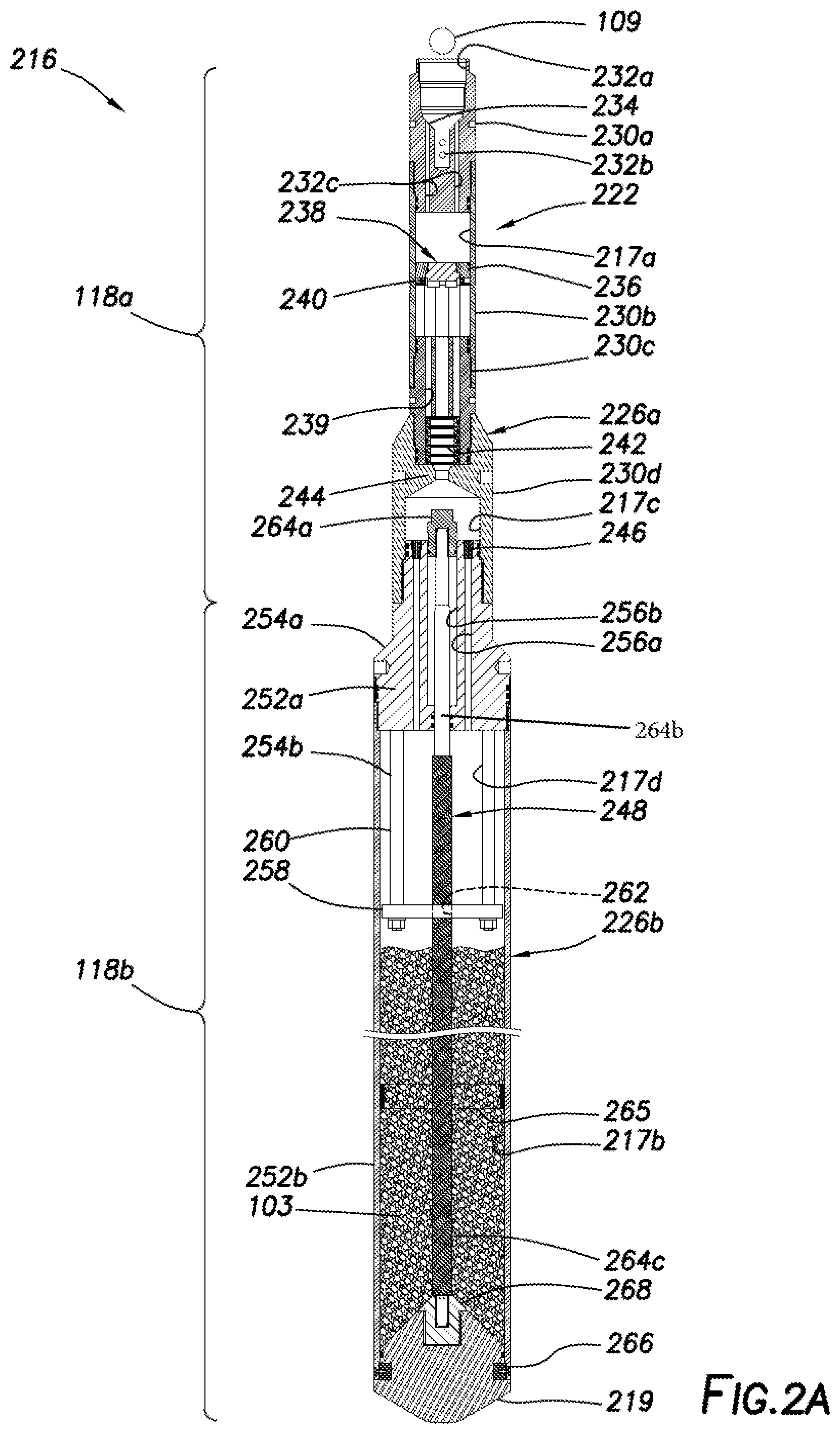
FIGS. 2A-2B show an example ball actuated placement tool 216. This version includes an actuation portion 118a, a placement portion 118b, and an actuation assembly 222. The actuation portion 118a is triggered by the ball 109. The actuation portion 118a includes an actuator housing 226a with the fluid chamber 217a therein. The housing 226a may be a modular member including a series of threadedly connected subs, collars, sleeves, and/or other components. In this version, the housing 226a includes a circulation sub 230a, a piston collar 230b, a filtration sub 230c, and an actuator crossover 230d.
The circulation sub 230a has a fluid inlet 232a connectable to the conveyance (e.g., 112 of FIG. 1) to receive the fluid therefrom, and an exit port 232b to release the fluid into the wellbore 105. The circulation sub 230a also has fluid passageways 232c for passing at least a portion of the fluid into the fluid chamber 217a.
The circulation sub 230a has a ball seat 234 positioned between the inlet 232a and the exit port 232b. The ball seat 234 is shaped to sealingly receive the ball 109. Once seated in the ball seat 234, the ball 109 closes the exit port 232b to prevent fluid from exiting therethrough. With the ball 109 seated, the fluid previously exiting the exit port 232b now passes through fluid passageways 232c and into the fluid chamber 217a with the other fluid entering the circulation sub 230a through the fluid inlet 232a.
The piston collar 230b may be a tubular sleeve located between the circulation sub 230a and the filtration sub 230c, and is threadedly thereto. The piston collar 230b may have ends shaped to receive portions of the circulation and filtration subs 230a,c. The piston collar 230a has a support 236 along an inner surface thereof a distance downhole from the circulation sub 230a. The support 236 may have a circular inner periphery shaped to receive a shear piston 238.
The shear piston 238 may be a disc shaped member removably seated in the support 236 by shear pins (or screws) 240. The shear piston 238 and support 236 may define a fluid barrier to fluidly isolate the fluid in the fluid chamber 217a entering the placement portion 118b. Once sufficient force (e.g., pressure) is applied to the shear pins 240, the shear piston 238 may be released to allow the fluid to pass from the fluid chamber 217a and into the placement portion 118b as is described further herein.
The filtration sub 230c is positioned between the piston collar 230b and the actuator crossover 230d. The filtration sub 230c may be a tubular member in fluid communication with the fluid chamber 217a once the shear piston 238 is released. The filtration sub 230c has a fluid passage 239 therethrough that reduces in cross-sectional area to slow the flow of fluid as it passes therethrough.
The filtration sub 230c may have one or more filters 242 positioned along the tapered fluid passage 239 defined within the filtration sub 230c. One or more filters 242 may be positioned (e.g., stacked) inside the filtration sub 230c to filter the fluid as it passes from the fluid chamber 217a and into the placement portion 118b. The filters 242 may be conventional filters capable of removing solids, debris, or other contaminants from the fluid passing therethrough. The filters 242 may be configured from fine to course filtration by selectively defining mesh or other filtration components therein.
The actuator crossover 230d is threadedly connected between the filtration sub 230c and the placement portion 118b. The actuator crossover 230d has a tapered outer surface with an outer diameter that increases to transition from an outer diameter of the filtration sub 230c to an outer diameter of an uphole end of the placement portion 118b. The actuator crossover 230d has a tubular inner surface that is shaped to receive the filtration sub 230c at one end and the uphole end of the placement portion 118b at the other end, with a fluid restriction 244 defined therebetween. The fluid restriction 244 is positioned adjacent an outlet of the fluid passage 239 of the filtration and the filters 242 to receive the filtered fluid therethrough.
The placement portion 118b is threadedly connected to a downhole end of the actuation portion 118a adjacent the actuator crossover 230d with an actuation chamber 217c defined therein. The placement portion 118b includes a placement housing 226b, metering jets (or valves) 246, and a push down piston 248. The housing 226b includes a metering sub 252a, a placement sleeve 252b, and the door 219, with the pressure chamber 217b defined therein.
The metering sub 252a is threadedly connected between the actuator crossover 230d and the placement sleeve 252b. The metering sub 252a includes a piston portion 254a and a passage portion 254b. The piston portion 254a has an uphole end threadedly connectable to the actuator crossover 230d and is receivable therein. The piston portion 254a also has a downhole end threadedly connected to the placement sleeve 252b and extending therein. The piston portion 254a has an outer surface between the uphole and downhole ends that is shaped to increase from an outer diameter of the actuator crossover 230d to an outer diameter of the placement sleeve 252b.
The piston portion 254a of the metering sub 252a is a solid member with metering passages 256a and a piston passage 256b extending therethrough. The metering jets 246 are positioned in the metering passages 256a to selectively allow the filtered fluid in the actuation chamber 217c to pass therethrough. The metering jets 246 may be selected to alter (e.g., reduce) flow of the fluid passing through the metering passages 256a and into the passage portion 256b.
The passage portion 254b includes a passage plate 258 supported from the piston portion 254a by long bolts 260. A dry plate chamber 217d is defined between the passage plate 258 and the metering sub 252a. The passage plate 258 has a hole 262 to receive the piston 248 and permit passage of fluid therethrough. The holes 262 may be defined to allow fluid to pass at a selected (e.g., reduced) rate.
The push down piston 248 extends through the metering sub 252a and the placement sleeve 252b. The push down piston 248 includes a piston head 264a, a push rod 264b, and a tube sleeve (screen) 264c. The piston head 264a extends from an uphole end of the push down piston 248 and into the actuation chamber 217c. The push rod 264b is connected to the piston head 264a at an uphole end and the door 219 at a downhole end.
The push rod 264b may be provided with various options. For example, the tube sleeve 264c extends about a downhole portion of the push rod 264b, and has perforations for the passage of the fluid therethrough. An end view of the push rod 264b and the tube sleeve 264c is shown in greater detail in FIG. 3A. In another example, a centralizer 265 may be positioned in the placement sleeve 252b. The push rod 264b passes through the centralizer 265 and is slidingly supported centrally therein. As shown in greater detail in FIG. 3B, the centralizer 265 may have a central hub to slidingly receive the push rod 264b, and spokes connected to an outer ring to support the hub and the push rod 264b centrally within the placement sleeve 252b.
Referring back to FIGS. 2A and 2B, the door 219 may be provided with a receptacle (or connector) 268 for receivingly connecting to the downhole end of the push rod 264b. The door 219 is removably secured to a downhole end of the placement sleeve 252b by shear pins 266. The pressure chamber 217b is defined between the door 219 and the metering sub 252a to house the wellbore material 103. The push rod 264b is slidably positionable through the metering sub 252a in response to fluid forces applied to the piston head 264a and/or the forces applied to the door 219 to selectively release the wellbore material 103 as is described further herein.
During operation, the fluid from the surface passes through fluid passageways 232c, 239, 256a and the various fluid chambers within the placement tool 216. These passageways and chambers define a fluid pathway through the placement tool 216. Various devices along these passageways, such as the piston (disc) 238 and support 236, form the actuation assembly 222 that selectively releases the fluid through the actuation portion 118a and into the placement portion 118b to cause the door 119 to open and release the wellbore material 103.
FIGS. 4A-4C show operation of the ball actuated placement tool 216. These figures show the placement tool 216 in a run-in mode, an actuated mode, and a placement mode, respectively. In the run-in mode of FIG. 4A, the placement tool 216 is positioned in the wellbore 105 to a given depth. The fluid from the fluid source 106 (FIG. 1) is pumped via the conveyance 112 into the inlet 232a. A portion of this fluid passes through the fluid passageways 232c and into the fluid chamber 217a. A remaining portion of this fluid passes out exit port 232b and into the wellbore 105 as indicated by the curved arrows. In this position, the fluid in fluid chamber 217a is insufficient to shear the shear piston 238. The fluid is, therefore, unable to pass into the placement portion 118b, and the wellbore material 103 in the pressure chamber 217b remains dry and protected.
In the actuated mode of FIG. 4B, the ball 109 has been released through the conveyance 112 and seated in the ball seat 234 to trigger actuation of the actuation assembly 222. Once seated, the ball 109 blocks the exit port 232b, thereby forcing all fluid entering inlet 232a to pass through the fluid passageways 232c and into the fluid chamber 217a. The increase in fluid causes sufficient force to shear the shear pins 240 and release the shear piston 238 from the support 236. With the shear piston 238 released, the fluid in fluid chamber 217a is free to pass through the filtration sub 230c for filtering, and into the actuation chamber 217c.
The filtered fluid in the actuation chamber 217c passes through metering jets 246 and the passage plate 258, and into the pressure chamber 217b. The configuration of the inlets, passages, passageways, valves, plate, and other fluid channels through the placement tool 216 may be shaped to manipulate (e.g., reduce) flow of the fluid into the pressure chamber 217b to prevent damage to the wellbore material 103 which may occur from hard impact of fluid hitting the wellbore material 103. At this point, the fluid pressure in the actuation chamber 217c is insufficient to move the piston 248 and/or open the door 219. The wellbore material 103 has been invaded (e.g., surrounded) by the fluid, but has not yet reacted. The wellbore material 103 may be configured to react after a delay to allow the wellbore material 103 to release before reaction.
In the placement mode of FIG. 4C, the pressure in actuation chamber 217c has increased and/or the fluid in the pressure chamber 217b has increased to an actuation level sufficient to drive the piston 248 downhole. The forces applied to the piston 248 by the fluid in the chambers 217c,b is sufficient to cause the piston 248 to shift downhole and to shear the shear pins 266 attached to the door 219. In this position, the door 219 opens and releases the invaded wellbore material 103 into the wellbore 105.
The invaded wellbore material 103 may be selected such that it reacts after leaving the placement tool 216. For example, the wellbore material 103 may be a material reactive to water passing into the pressure chamber 217b. To prevent the material from sticking within the placement tool 216, the reaction may be delayed such that the wellbore material 103 reacts with the fluid in the wellbore 105 to form the wellbore mixture (or fluidized or hydrolized wellbore material) 103', such as a sealant capable of sealing a portion of the wellbore 105. In at least some cases, the sealant may be used to sealingly enclosed items (e.g., hazardous material) at a subsurface location. The process may be repeated to allow for layers of sealant to be applied to secure such items in place.
In an example operation for placing a sealant as the wellbore material 103 in the wellbore 105, the placement tool 216 may be deployed into the wellbore 105 by the conveyance 112. The placement tool 216 may be positioned at a desired location in the wellbore, such as about 10 feet (3.05 m) above a location for performing a wellbore operation. The ball 109 may be placed in the conveyance 112, and fall to its position in the seat 234. As fluid pumps through the conveyance 112, a pressure in the chamber 217a increases until the shear pins 240 shear and release the shear piston 238. The fluid is at a pressure of about 3,000 psig (206.84 Bar) as it is now free to rush through the filtration sub 230c and into the actuation chamber 217c.
The fluid in the actuation chamber 217c flows through the metering jets 246. The metering jets 246 slow down the volume and rate of advancement of the fluid as it passes into the dry plate chamber 217d. The fluid fills the plate chamber 217d and passes through an annular gap between the push rod 264b and the tube sleeve 264c. As the fluid passes through the annular gap, the fluid also flows to a top of the door 219 and radially into the pressure chamber 217b. The fluid floods the pressure chamber 217b in about 60 seconds. This flooding may occur with a minimal pressure drop or compressive forces applied to the wellbore material 103.
The pressure in the pressure chamber 217b increases until it reaches equilibrium, namely when the pressure in the pressure chamber 217b equals the pressure of the conveyance and the wellbore pressure at the placement depth. The placement tool 216 may be provided with pressure balancing to isolate chambers 217a-c from external pressures before release of the wellbore material 103 (e.g., sealant). During this time, the fluid in the fluid chambers 217a may be maintained at 1 atm psia (atmospheric pressure) (6.89 kPa), and fluid in the pressure chambers 217b may be maintained at 1 atm psig (108.22 kPa) (gauge pressure).
While in equilibrium, the push piston 248 pushes the push rod against the door 219. This force eventually shears the shear pins 266 and releases the door. The door 219 pushes about 6 inches (15.24 cm) out of the placement tool and separates from the push rod 264b. With the door 219 open, the wellbore material 103 falls into the wellbore 105, disperses, and collects atop its intended platform. The wellbore material 103 may react (e.g., swell) after exposure to wellbore fluid in the wellbore 105.
FIG. 5 show an example electro-hydraulic placement tool 516. The placement tool 516 includes an actuation portion 518a, the placement portion 118b, and an actuator 522. In this version, the actuation portion 518a is triggered by an electro-hydraulic signal from the surface. The actuation portion 518a includes a housing 526a with the fluid chamber 517a therein. The housing 526a includes a trigger sub 530a, a tandem sub 530b, a filtration sub 530c, and the actuator crossover 230d.
The trigger sub 530a may be a cylindrical member with an upper portion electrically connectable to the conveyance (e.g., a wireline 112 not shown). The trigger sub 530a includes a transceiver 509, hydraulic plugs 532, and the fluid chamber 517a. The transceiver 509 may be an electrical communication device capable of communication with the trigger 110 (FIG. 1) for passing signals therebetween. The transceiver 509 may be wired via the conveyance 112 and/or wirelessly connected to the trigger 110 for receiving an actuation signal therefrom. The trigger sub 530a may have the fluid chamber 517a therein and the hydraulic plugs 532 extending therethrough. The fluid chamber 517a may receive wellbore fluid from the wellbore 105 via holes in the tandem sub 530b.
The tandem sub 530b may be a tubular sleeve threadedly connected between the trigger sub 530a and the filtration sub 530c. The tandem sub 530b includes a rupture piston 536 and rupture disc 538. The rupture piston 536 includes a base 570a and a piercing rod 570b. The base 570a is fixed to an inner surface of the tandem sub 530b. The piercing rod 570b is extendable from the base 570a. The piercing rod 570b may be selectively extended by signal from the trigger 110.
The rupture disc 538 may be seated in the tandem sub 530b to fluidly isolate the fluid chamber 517a from the placement portion 118b. The rupture disc 538 may be ruptured by actuation of the piercing rod 570b. Upon receipt of the trigger signal, the piercing rod 570b may be extended to pass through the rupture disc 538. The piercing rod 570b pierces the rupture disc 538 to allow the fluid to pass from the fluid chamber 517a therethrough.
The filtration sub 530c is threadedly connected between the tandem sub 530b and the actuator crossover 230d. The filtration sub 530c may be similar to the filtration sub 230c previously described. In this version, the filtration sub 530c has a tapered outer surface that increases in diameter from the tandem sub 530b to the actuator crossover 230d. The rupture disc 538 is positioned at an uphole end of the filtration sub 530c to allow fluid to pass therethrough upon rupturing. The filtration sub 530c has the filters 242 therein.
The actuator crossover 230d is threadedly connected between the filtration sub 530c and the placement portion 118b, and operates as previously described to pass fluid from the fluid chamber 517a to the placement portion 118b for actuating the piston 248 and the door 219 to release the wellbore material 503 from the pressure chamber 217b and into the wellbore 105 as previously described. The wellbore material 503 in this version is a sand disposable in the wellbore 105.
FIGS. 6A and 6B show operation of the electro-hydraulic placement tool 516 in an actuated mode and a placement mode, respectively. FIG. 6A shows the placement tool 516 positioned at a desired depth in the wellbore 105. Fluid from the wellbore 105 passes into the fluid chamber 517a via holes in the tandem sub 530b. A signal has been sent to trigger the rupture piston 536 to extend the piercing rod 570b through the rupture disc 538. The ruptured disc 538 allows the fluid to pass from the fluid chamber 517a through into the filtration sub 530c and into the actuation chamber 217c.
The fluid pressure in actuation chamber 217c passes into the pressure chamber 217b to invade the wellbore material 503. Upon exposure to the wellbore fluid, the wellbore material 503 quickly forms a fluidized wellbore material 503'. At this point, the forces are insufficient to move the push down piston 248 or open the door 219.
FIG. 6B shows the electro-hydraulic placement tool 516 after the pressure in the placement tool 516 has increased to a level sufficient to drive the push down piston 248 and the door 219 downhole, and to allow the release of the fluidized wellbore material 503' into the wellbore 105. The fluidized wellbore material 503' may be released into the wellbore 105 for performing downhole operations therein.
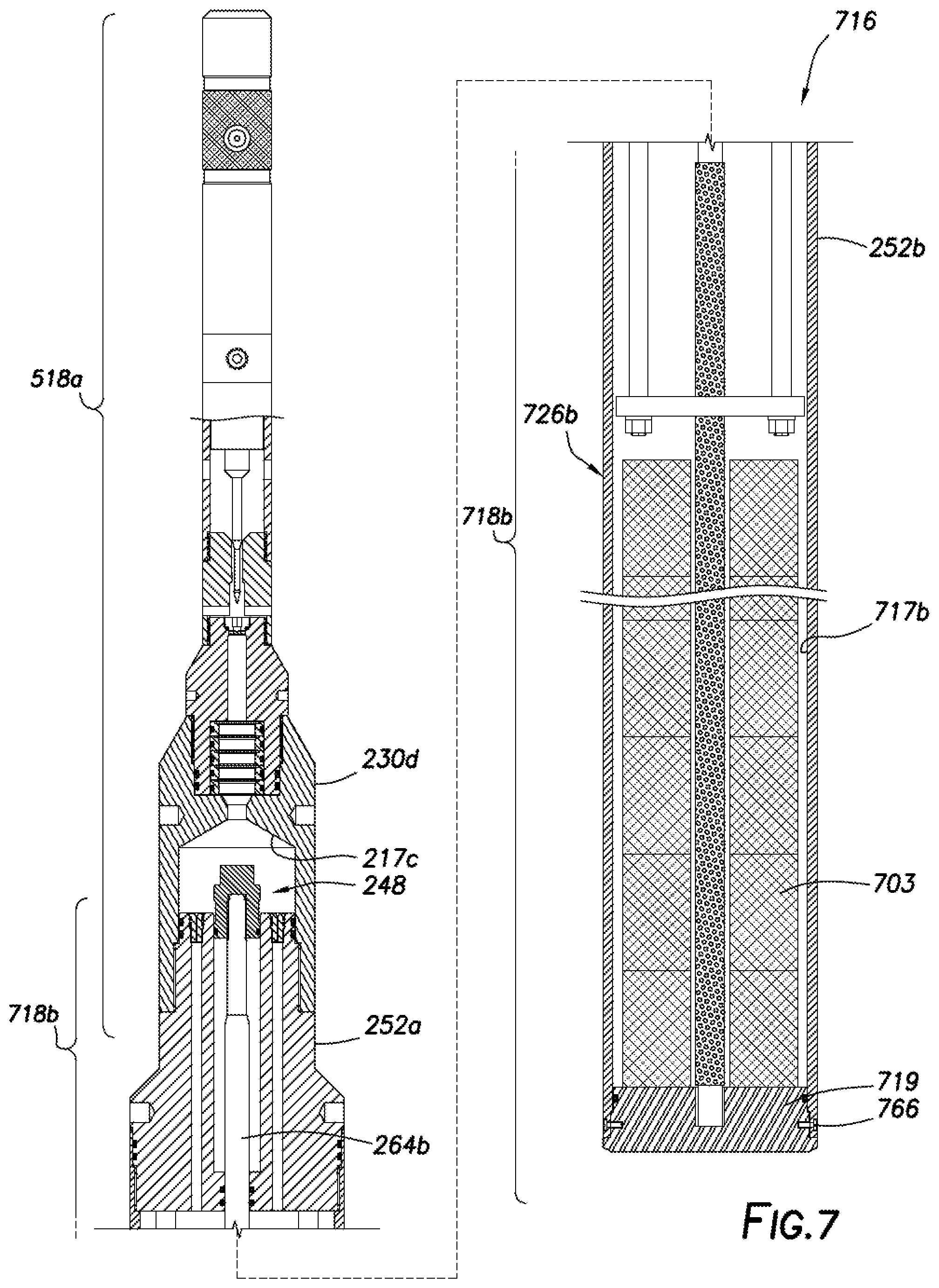
FIG. 7 show another example downhole placement tool 716 with a modified placement portion 718b and a pierce actuator. The placement tool 716 includes the actuation portion 518a and a placement portion 718b. The actuation portion 518a is the same as previously described in FIG. 5. In this version, the placement portion 718b is threadedly connected to a downhole end of the actuation portion 518a adjacent the actuator crossover 230d.
The placement portion 718b is similar to the placement portion 118b, except that the housing 726b and the door 719 have a pressure chamber 717b shaped to store a wellbore material in the form of wellbore blocks 703 therein. The housing 726b may include the metering sub 252a and a placement sleeve 252b with the door 719 secured by the shear pins 766. The metering sub 252a operates as previously described to pass fluid from the actuation chamber 217c and into the pressure chamber 717b to invade the wellbore blocks 703. The pressure chamber 717b is depicted as a cylindrical chamber, and the door 719 is depicted as having a cylindrical shape with a flat surface to support the wellbore blocks 703.
The wellbore blocks 703 may be a set of cuboid shaped blocks stacked within the pressure chamber 717b. The blocks may optionally be in the form of donut shaped discs stackable within the pressure chamber 717b with the push rod 264b of the push down piston 248 extending therethrough. As demonstrated by FIG. 7, the wellbore material 703 may have a variety of shapes, and the placement portion 718b may be conformed to facilitate storage and placement thereof.
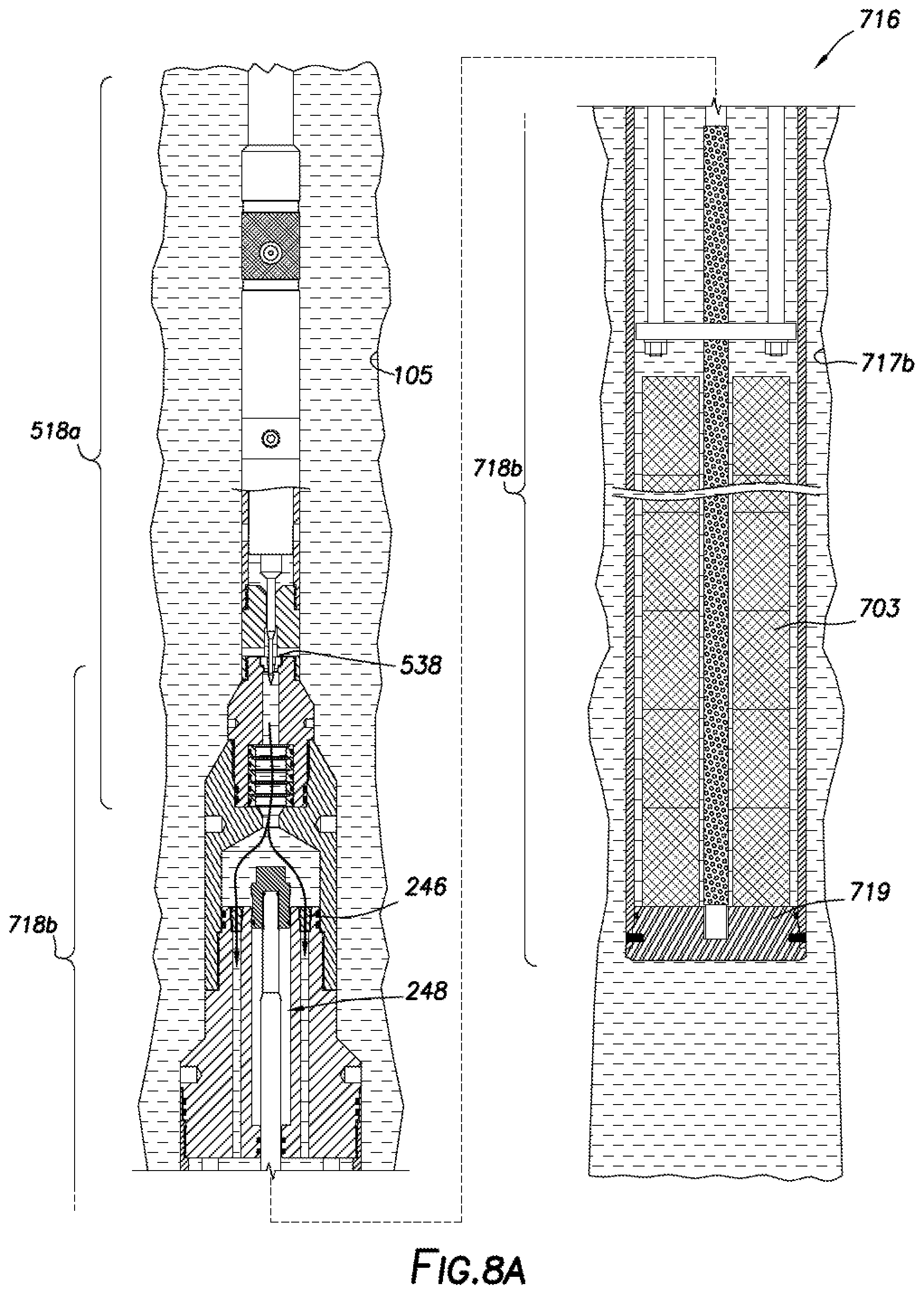
FIGS. 8A and 8B show operation of the block release placement tool 716 in an actuated mode and a placement mode, respectively. FIG. 8A shows the placement tool 716 positioned at a desired depth in the wellbore 105. In this view, the wellbore fluid has passed into the actuation portion 518a, through the pierced rupture disc 538 and to the placement portion 718b as previously described. The fluid in the placement portion 718b passes through the metering jets 246 and into the pressure chamber 717b to invade the wellbore blocks 703. In this view, the forces in the placement portion 718b are insufficient to drive the push down piston 248 and the door 719 downward.
FIG. 8B shows the block release placement tool 716 after the pressure in the placement tool 716 has increased to a level sufficient to drive the push down piston 248 and the door 719 downhole, and to allow the release of the wellbore blocks 703 into the wellbore 105. The wellbore blocks 703 are deployed into the wellbore 105 upon breakage of the shear pins 766 and the release of the door 719.
FIGS. 9A-9G show various configurations of the wellbore material including pellet, block, cylindrical, and fluted configurations. One or more of these and/or other wellbore materials as shown may be used in one or more of the various placement tools described herein. Various combinations of the features (e.g., size, geometry, quantity, shape, etc.) of one or more of the wellbore materials may be used.
FIG. 9A shows a pellet shaped wellbore material 103. The pellet shaped material is shown as a spherical component, such as a ball. Examples of the pellet wellbore material 103 are shown in use in the placement tool 216 of FIGS. 2A, 4A-4C, 10A-11C, and 13A-14B.
FIG. 9B shows a block shaped wellbore material 703a. The block wellbore material 703a is shown in use in the placement tool 716 of FIGS. 7 and 8A-8B. FIGS. 9C and 9D show a perspective and a cross-sectional view (taken along line 9D-9D) of another version of the block shaped material 703b usable in the placement tool 716 of FIG. 7. In this version, the block has a cylindrical shape positionable in the tool 716 with the rod extending through a central passage therein. The cylindrical wellbore material 703b may be cut into portions as indicated by the cross-sectional view of FIG. 9D.
FIGS. 9E-9G show perspective, top, and longitudinal cross-sectional views, respectively, of a fluted shaped wellbore material 903. This version is a cylindrical member with a central hub 973a and radial wings 973b extending therefrom. This version is similar to the cylindrical version of FIG. 9C, except that the central passage has been removed and the radial cuts 973c have been added.
Each of the wellbore materials includes an outer coating 972a and a core 972b. The coating 972a may be a fluid soluble material, such as sugar, that surrounds and protects the core 972b during transport. The coating 972a may encase the core 972b until sufficient exposure of fluid (e.g., water, drilling mud, etc.) disintegrates the coating 972a as is described further herein (see, e.g., FIGS. 10A-11C). The core 972b may be a solid and/or liquid usable in the wellbore, such as a sealant (e.g., bentonite), polymer, mud, acid, pellets, sand, blocks, epoxy, and/or other material. The core 972b may be a material that reacts with the fluid to form a sealing material capable of sealing a portion of the wellbore.
As shown in the fluted configuration of FIGS. 9E-9G, the fluted shaped wellbore material 903 is provided with radial wings 973b defined by extending radial cuts towards the central hub. The radial cuts may provide additional surface area for the coating 972a to cover portions of the core 972b. In some cases, it may be helpful to reduce a thickness of the core 972b to allow sufficient fluid to seep into and mix with all portions of the wellbore material 903, thereby activating its sealing capabilities. The fluted wellbore material 903 may also be provided with bevels 973d, shoulders 973e, and/or other features. The radial cuts in the fluted wellbore material 903 may be used to increase the surface area by an amount of, for example, about 145%.
The fluted wellbore material 903 may be shaped to facilitate placement into and/or use with the placement tool (e.g., 1216 of FIG. 12A) as is described further herein. By way of example, dimensions of the fluted wellbore material 903 include an outer diameter of about 4.50 inches (11.43 cm), a height of about 3.75 inches (9.52 cm), a shoulder of about 0.5 inches (12.70 mm) at one end, a chamber of about 0.38 inches (9.65 mm).times.about 45 degrees at an opposite end, and eight radial flutes each of about 1.50 inches (3.81 cm).times.0.25 inches (6.35 mm) and about 45 degrees F. (7.22 C).
FIGS. 10A-11C depict the downhole placement tool of FIG. 2A during a drop placement operation. In FIGS. 10A-10C, the downhole placement tool 216 is depicted in a run-in mode, actuated mode, and a placement mode, respectively. As described previously, the wellbore material 103 is isolated in the placement sleeve 252b (FIG. 10A) until the placement tool 216 is activated by pressure (FIG. 10B) to open the door 219 (FIG. 10C).
As shown in the detail of FIG. 10A, placement tool 216 is carrying the pellet wellbore material 103 in its original state with the coating 972a disposed about the core 972b. The wellbore material 103 is maintained in a dry state (FIG. 10A) until the wellbore fluid 1074 is passed into the pressure chamber 217b to form the fluidized wellbore material (or wellbore mixture) 103' (FIG. 10B), and the fluidized wellbore material 103' is released into the wellbore 105. The wellbore material 103 may be placed under pressure in the placement tool 216 to prevent a surge of fluid (e.g., water) from entering and pushing into the system. Temperature inside may not increase like it would with air, so heat transfer may be limited to radiation and conduction through the pellet wellbore material 103. During this time, the wellbore material 103 may be conveyed in a vacuum to allow a reaction with fluid to be more inert. The fluidized wellbore material 103' may then be exposed to the wellbore fluid 1074. Once exposed to the wellbore fluid 1074, the core 972b of the fluidized wellbore material 103' may start to disintegrate, but the core 972b is not yet exposed to the wellbore fluid 1074.
FIGS. 11A-11C show activation of the wellbore material 103 during the wellbore drop operation. As shown in these views, the door 219 is opened and the fluidized wellbore material 103' is released from the downhole placement tool 216. The fluidized wellbore material 103' falls through the wellbore 105. As the fluidized wellbore material 103' falls through the wellbore 105, the wellbore fluid 1074 passes over the fluidized wellbore material 103' as indicated by the arrows. As the wellbore fluid 1074 passes over the fluidized wellbore material 103', the coating 972a washes away as shown in the detail of FIG. 11A. Because the fluidized wellbore material 103' is moving through the wellbore 105, the fluidized wellbore material 103' engages fresh wellbore fluid 1074 along the way with fresh capabilities of washing away the coating 972a as indicated by the arrows and droplets. This falling action thereby provides both an abrasive action of the wellbore fluid 1074 passing over the fluidized wellbore material 103' and a washing action caused by engagement with the fresh wellbore fluid 1074 as the fluidized wellbore material 103' reaches new depths.
The fluidized wellbore material 103' may fall a sufficient distance to allow the wellbore fluid 1074 to engage the fluidized wellbore material 103' and remove the coating 972a. The distance may be, for example, from about 100-200 feet (30.48-60.96 m). By removing the coating 972a, the core 972b of the fluidized wellbore material 103' is exposed to the wellbore fluid 1074 and reacts therewith to form an activated wellbore material 103''. Once the core 972b of the fluidized wellbore material 103' reacts with the wellbore fluid 1074, the fluidized wellbore material 103' is converted to activated wellbore material 103''. The activated wellbore material 103'' has adhesive capabilities for securing the activated wellbore material 103'' in place in the wellbore 105. The activated wellbore material 103'' may then seat in the wellbore 105 as shown in FIG. 11C.
In an example, a wellbore material 103 made of sodium (NA) bentonite pellets having a bentonite core and a fluid (e.g., water) soluble coating is provided. The downhole placement tool 216 is loaded with 150 lb-mass (68.04 kg) of the wellbore material. The downhole placement tool 216 is lowered to a depth of 9,800 ft (2.99 km) and 250 degrees F. (121.11 C) downhole. The placement tool 216 stops descending and then reverses motion so that it ascends at a rate of 10 m/min. During the ascension, the placement tool 216 is actuated to fluidize the wellbore material 103, and to release the fluidized wellbore material 103' as the downhole tool rises. The fluidized wellbore material 103' falls a distance D of 200 ft (60.96 m) through the wellbore to a position for sealing. During the drop, the wellbore fluid 1074 washes over the fluidized wellbore material 103', removes its coating 972a, and exposes its core 972b. The core 972b of the fluidized wellbore material 103' is exposed to the wellbore fluid 1074 and reacts therewith. The activated wellbore material 103'' is secured in the wellbore 105 to form a seal in the wellbore 105.
Once released, the fluidized wellbore mixture 103' may move out of the placement tool 216 and flow laterally outward and upward around a gap between the placement tool 216 and a wall of the wellbore 105 at an upward casing/tool annular fluid velocity. When run into the hole on coiled tubing, fluid may be pumped into the wellbore at a constant rate (pump-down fluid rate) of about 0.25 barrels per minute (29.34 L/min). The placement tool 216 may be activated by dropping the ball 109 into the tool after some pumping (e.g., about 15-20 minutes).
During the wellbore drop operation, the placement tool 216 may then be retracted a distance uphole (tool pull out of hole (POOH)) by pulling the conveyance (e.g., coiled tubing) and then pumping again. The conveyance may be retracted at a velocity of, for example, about 25 ft/min (12.7 m/min) when fluid is flowing at a flow rate of about 10 ft/min (5.08 m/min). This may be used to prevent the placement tool 216 from sticking in the wellbore 105. After pumping again, the placement tool 216 floods the chamber 217b with fluid until its internal pressure builds to equal wellbore pressure outside the placement tool 216. Once the internal pressure increases over the wellbore pressure by about 200-400 psid+ (1378.95-2757.90 kPa), the shear pins 266 are sheared and the door 219 opens to release the fluidized wellbore material 103'. The fluidized wellbore material 103' may then fall downhole rather than passing around the placement tool 216 and flowing uphole.
Table 1 below shows example placement parameters that may be used for placement of NA-Bentonite pellets when using the placement tool.
TABLE-US-00001 TABLE 1 NA-BENTONITE PELLETS PLACEMENT: POOH Rates for use after Actuation Casing ID Tool OD (in)/(cm) = 6.45/16.38 (in)/(cm) = 5.50/13.97 Casing/Tool Casing Diametral Diametral Annular Annular Gap Flow Area (in)/(cm) = 0.95/2.41 (in.sup.2)/(cm.sup.2) = 8.91/22.63 Upward Pump-down Pump-down Casing/Tool Fluid Rate Fluid Rate Annular Fluid Recommended. (barrels/min)/ (gallons/min)/ Velocity Tool POOH rate (L/min) (L/min) (ft/min)(m/min) (ft/min)/(m/min) 0.10/11.73 4.20/15.90 9.1/2.77 23/7.01 0.15/17.60 6.30/23.85 13.6/4.15 34/10.36 0.20/23.47 8.40/31.80 18.1/5.52 45/13.72 0.25/29.34 10.50/39.75 22.7/6.92 57/17.37 0.30/35.20 12.60/47.70 27.2/8.29 68/20.73 0.35/41.07 14.70/55.65 31.8/9.69 79/24.08 0.40/46.94 16.80/63.60 36.3/11.06 91/27.74 0.45/52.81 18.90/71.54 40.8/12.44 102/31.09 0.50/58.67 21.00/79.49 45.4/13.84 113/34.44 0.55/64.54 23.10/87.44 49.9/15.21 125/38.1
where Casing ID is the inner diameter of the casing in the wellbore, the Tool OD is an outer diameter of the placement tool, and POOH is the pull out of hole rate.
FIGS. 12A and 12B are cross-sectional and exploded views, respectively, of an example peripheral downhole placement tool 1216. The peripheral placement tool 1216 includes the actuation portion 118a of FIG. 2A and a modified placement portion 1218b. In this version, the placement portion 1218b is threadedly connected to a downhole end of the actuation portion 118a adjacent the actuator crossover 230d.
The placement portion 1218b is similar to the placement portion 118b including the same metering jets 246, metering sub 252a, placement sleeve 252b (with pressure chamber 217b therein), piston head 264a, and shear pins 266. In this version, the passage plate 258 and long bolts 260 of FIG. 2A have been removed and the push rod 264b, tube sleeve 264c, and door 219 have been replaced with a screen rod 1264b, peripheral screen 1264c, and door 1219. The screen rod 1264b has an end receivable by the metering sub 252a and an opposite end connected to an uphole end of the peripheral screen 1264c.
The uphole end of the peripheral screen 1264c has a plate connected to the screen rod 1264b for movement therewith. As pressure is applied to the screen rod 1264b, the screen rod 1264b is advanced downhole, thereby driving the plate and attached peripheral screen 1264c downhole. This action increases pressure in the placement sleeve 252b which ultimately ruptures the shear pins 266 opens the door 1219 to release the wellbore material 903.
The wellbore material 903 is shown as the fluted blocks 903 stacked within the placement sleeve 252b. The peripheral (perforated) screen 1264c lines the placement sleeve 252b and provides a minimal annulus for fluid flow therebetween. This annulus permits fluid flow along a periphery of the fluted wellbore material 903 to engage the fluted material 903 and penetrate into its radial cuts 973c (FIG. 9E). The radial cuts 973c in the fluted blocks 903 allow fluid to pass axially through the pressure chamber 217b. The peripheral screen 1264c is positioned radially about the fluted blocks 903 to facilitate flow of fluid therethrough.
FIGS. 13A-14B show the placement tool 1216 during the wellbore drop operation. As shown in this example, the placement tool 1216 may be used with the pellet wellbore material 103 (or other wellbore material). FIGS. 13A-13C are similar to FIGS. 10A-10C and show the downhole placement tool 216 in a run-in mode, actuated mode, and a placement mode, respectively. FIG. 13A shows the placement tool 1216 positioned at a desired depth in the wellbore 105. In this view, the wellbore fluid 1074 has passed into the actuation portion 118a. FIG. 13B shows the fluid after it enters the placement portion 1218b and into the pressure chamber 1217b to invade and form the fluidized wellbore material 103'.
FIG. 13C shows the placement tool 1216 after the pressure in the placement tool 1216 has increased to a level sufficient to push down the peripheral screen 1264c and release the door 1219. The door 1219 opens to allow the fluidized wellbore material 103' to fall into the wellbore 105. As also shown in this view, the screen rod 1264b and peripheral screen 1264c are driven downhole to apply a force to shear the pins 266 and release the door 1219. The fluidized wellbore material 103' is deployed into the wellbore 105 upon breakage of the shear pins 266 (FIG. 12B) and the release of the door 1219.
FIG. 14A-14B show activation of the wellbore material 103 during the wellbore drop operation. As shown in these views, the fluidized wellbore mixture 103' falls into the wellbore 105 and the coating 972a (FIGS. 11A-11C) is removed as the fluidized wellbore material 103' falls through the wellbore. The fluidized wellbore material 103' falls through the wellbore 105 and is activated to form the activated wellbore material 103'' as described in FIGS. 11A and 11B.
FIG. 15 shows a method 1500 of sealing a wellbore. As shown in this example, the method 1500 involves 1580--deploying a placement tool with a wellbore material therein into a wellbore, the wellbore material comprising a core and a coating, 1582--positioning the placement tool at a depth a distance d above a sealing depth of the wellbore, and 1584--fluidly actuating the placement tool to mix a fluid with the wellbore material to form a fluidized wellbore material and to open a door to release the fluidized wellbore material into the wellbore. The placement tool and wellbore material may be those described herein.
The method continues with 1586--activating the wellbore material by releasing the fluidized wellbore mixture into the wellbore such that a coating of the fluidized wellbore material is washed off with wellbore fluid and the core reacts with the wellbore fluid as the fluidized wellbore material passes through the wellbore, and 1588--allowing the activated wellbore material to form a seal about the wellbore.
The method may be performed in any order and repeated as desired.
FIGS. 16A-16C show another example deflector placement tool 1616. This version includes an actuation portion 1618a, a placement portion 1618b, and an actuator crossover 1630d. The actuation portion 1618a includes a housing 1626 with the fluid chamber 1617a and an actuation assembly 1622 therein. The housing 1626 includes circulation sub 1630a, a piston collar 1630b, and a plug sub 1630c. The circulation sub (ball actuator) 1630a may be a ball actuated sub, such as 230a of FIG. 2A or a hydro-electric actuated sub, such as 530a of FIG. 5A.
The piston collar 1630b may be a tubular sleeve located between the circulation sub 1630a and the plug sub 1630c with the fluid chamber 1617a defined therein. The piston collar 1630b may have ends shaped to receive portions of the circulation and plug subs 1630a,c. The piston collar 1630a has a support 1636 along an inner surface thereof a distance downhole from the circulation sub 1630a. The support 1636 may have a circular inner periphery shaped to receive a shear piston 1638.
The shear piston 1638 may be a flange shaped member removably seated in the support 1636 by shear pins (or screws) 1640. The shear piston 1638 and the support 1636 may define a fluid barrier to fluidly isolate the fluid from entering the placement portion 1618b. An upper end of the shear piston 1638 is engagable by fluid passing into the housing 1626. The shear piston 1638 has an outer surface slidably positionable along an inner surface of the housing 1626. The shear piston 1638 also has tabs extending from a bottom surface thereof.
Once sufficient force (e.g., pressure) is applied to the shear pins 1640, the shear piston 1638 may be released to allow the fluid to pass from the fluid chamber 1617a and into the placement portion 1618b as is described further herein. Upon actuation by application of sufficient fluid force to the upper end of the shear piston 1638, the shear pins 1640 may be broken and the shear piston 1638 may be driven out of the support 1636 and against the plug sub 1630c as indicated by the downward arrow in FIG. 16A. The tabs on the bottom of the shear piston 1638 may contact the plug sub 1630c to define a flow gap G therebetween as shown in FIG. 16B.
The plug sub 1630c is a tubular member with a fluid passage 1639a therethrough. An uphole end of the plug sub 1630c is shaped for contact by the shear piston 1638 when activated. The shear piston 1638 is positionable against the plug sub 1630c with the flow gap G therebetween to permit the passage of fluid therethrough and into the passage 1639a.
A downhole end of the plug sub 1630c is connectable to the actuator crossover 1630d. The downhole end also has a plug insert 1633 seated within the plug sub 1630c. The plug insert 1633 has a plug 1637 to allow external access to the deflection chamber 1617a. The plug 1637 may be selectively removed to allow fluid to be inserted or exited through the plug insert 1633.
The actuator crossover 1630d is threadedly connected between the plug sub 1630c and the placement portion 1618b. The actuator crossover 1630d has a tapered outer surface with an outer diameter that increases to transition from an outer diameter of the plug sub 1630c to an outer diameter of an uphole end of the placement portion 118b. This tapered outer surface defines an upper portion and a lower portion.
The upper portion of the actuator crossover 1630d has a tubular inner surface that is shaped to receive the plug sub 1630c at one end. The upper portion also has a fluid passageway 1639b extending therethrough. The downhole portion of the actuator crossover 1630d is shaped to receive an upper end of the placement portion 1618b. A deflection chamber 1617a is defined in the downhole portion to receive the fluid passing from the fluid passageway 1639b.
A deflection plate 1658 is supported in a downhole end of the actuator crossover 1630d by a connector (e.g., screw, bolt, etc.). The deflection plate 1658 may be a circular member with a flat surface that faces an outlet of the deflection chamber 1617a to receive the fluid thereon. The deflection plate 1658 may be positioned in the deflection chamber 1617a a distance from an outlet of the passageway 1639b to receive an impact from force of the fluid applied by the fluid passing out of the passageway 1639b and into the metering sub 1652a. The deflection plate 1658 may be shaped and/or positioned to deflect such fluid laterally and/or to disperse the fluid through the deflection chamber 1617a. This may allow the fluid to pass through the passageway 1639b and against the deflection plate 1658 to absorb impact of the fluid and allow the fluid to flow into the placement portion 1618b at a slower rate.
The placement portion 1618b is threadedly connected to a downhole end of the actuation portion 1618a about a downhole end of the actuator crossover 1630d. The placement portion 1618b includes a housing 1626b and a push down piston 1648. The housing 226b includes a metering sub 1652a, a placement sleeve 1652b, and the door 1619, with the pressure chamber 1617b defined therein.
The metering sub 1652a is a tubular member with flow passages 1656a and a central passage 1656b for fluid flow therethrough. The metering sub 1652a is connectable to a downhole end of the actuator crossover 1630d to receive fluid flow therefrom and pass such fluid into the placement sleeve 1652b.
The metering sub 1652a also includes a metering assembly 1652c. The metering assembly 1652c includes a metering piston 1664a, a valve 1664b, and a push rod 1664c. The metering piston 1664a includes a piston head 1679a and a piston rod 1679b slidably positionable in the passage 1656b.
The piston rod 1679b extends from the piston head 1679a through the metering sub 1652a and into the placement sleeve 1652b. Shear pins 1666a are provided along the piston rod 1679b to prevent movement of the piston head 1679a until sufficient flow passes into the metering sub 1652a. The piston rod 1679b is slidably positionable through the valve 1664b. The push rod 1664c is connected to a downhole end of the piston rod 1679b and extends through the placement portion 1618b.
The metering sub 1652a is threadedly connected between the actuator crossover 1630d and the placement sleeve 1652b. The metering sub 1652a includes has an uphole end threadedly connectable to the actuator crossover 1630d and receivable in the deflection chamber 1617a and a downhole end threadedly connected to the placement sleeve 1652b and extending therein. The metering sub 1652a has an outer surface positioned between the actuator crossover 1630d and the placement sleeve 1652b.
The metering sub 1652a is a solid member with metering passages 1656a extending between the chamber 1617a and 1617b for fluid passage therethrough, and a piston passage 1656b for slidingly receiving the piston 1648 therethrough. The push down piston 1648 extends through the metering sub 1652a and the placement sleeve 1652b. The push down piston 1648 includes a piston head 1679a, a piston rod 1679b, and a push rod 1664c. The piston head 1679a is slidably positionable in the passage 1656b of the metering sub 1652a.
The piston rod 1679b is connected to the piston head and extends through the metering sub 1652a and into the pressure chamber 1617b. The push rod 1664c is slidably connected between the piston rod 1679b and the door 1619. The piston rod 1679b may be telescopically connected to the push rod 1664c and move axially therealong.
As the piston head 1679a is driven downward by fluid force from the fluid in chamber 1617a, the piston rod 1679b may slidingly pass along the push rod 1664c. The shear pins 1666a may be positioned about the piston rod 1679b to prevent movement of the piston 1648 until sufficient fluid force is generated. Once sufficient fluid force drives the piston head 1679a downward, the shear pins 1666a may be broken from the piston rod 1679b to allow the piston head 1679a and the piston rod 1679b to move.
The push rod 1664c may be hollow to permit fluid to pass into chamber 1617b therein. The valve 1664b may be positioned about the piston rod 1679b and the push rod 1664c to selectively permit fluid to pass into the push rod 1664c. The valve 1664b is a tubular sleeve secured in a downhole end of the metering sub 1652a in the passage 1656b. The valve 1664b has inlets to receive fluid from chamber 1617b therein. The inlets are in selective fluid communication with the chamber 1617c in the push rod 1664c depending on a position of the piston rod 1679b. The inlets of the valve 1664b are in the open position as shown in FIG. 16A until the piston head 1679a and the piston rod 1679b advance a predetermined distance downhole to close the inlets of the valve 1664b.
The placement sleeve 1652b may be a tubular member similar to the placement sleeves described herein. This placement sleeve 1652b is connected to a downhole end of the metering sub 1652a. The placement sleeve 1652b may be shaped to house the wellbore material (e.g., 103, 503, etc.) and the fluid passing into the pressure chamber 1617b.
The door 1619 is secured by shear pins 1666b to a downhole end of the placement sleeve 1652b. The door 1619 may be removed and the placement tool 1616 inverted to allow the placement sleeve 1652b to be filled with the wellbore material. Optionally, fluid may be placed into the pressure chamber 1617b prior to adding the wellbore material. As wellbore material is added, the fluid may be displaced and spill out of the pressure chamber 1617b. Once filled, the door 1619 may be closed, and the placement tool 1616 returned to its upright position for placement in the wellbore. Optionally, the chamber 1617b may be pressurized with air or vacuum.
When fluid contacts the piston head 1679a, the piston head 1679a and the piston rod 1679b are drive downward. Fluid flows through the inlets of the valve 1664b and into a chamber 1617c within the push rod 1664c as indicated by the arrows in FIG. 16B. Once the piston head 1679a bottoms out, the valve 1664b closes and prevents any additional fluid from passing into the push rod 1664c. The fluid from the metering sub 1652a may continue to pass into the placement sleeve 1652b. until the weight of the fluid and the wellbore material in the placement sleeve 1652b is sufficient to shear the shear pins 1666b in the door 1619.
The placement tool 1616 may have features described in other placement tools herein. For example, the housing and subs may be threadedly connected, filtration devices may optionally position in the placement tool 1616, various features of push rods may be used, and various wellbore materials may be positioned in the pressure chamber 1617b.
In an example operation, the placement tool 1616 is assembled and inverted for filling. Fluid, such as water, is placed in the pressure chamber 1617b having a 4'' (10.16 cm) internal diameter. Scoops of 0.25'' (0.63 cm) pellets of the wellbore material 103 is inserted into the pressure chamber 1617b and displaces 75% of the fluid. The door 1619 is secured on the tool 1616 to enclose the wellbore material 103 therein. The wellbore material 103 and fluid form a 10' (3.05 m) tall column of hydrated (fluidized) wellbore material 103'. The placement tool 1616 is then inverted to an upright position and the wellbore material 103' allowed to hydrate inside for 4 hours. The placement tool 1616 is positioned in a wellbore lined with acrylic casing having a 7'' (17.78 cm) outer diameter and a 6.5'' (16.51 cm) inner diameter. The placement tool is positioned 12' (3.66 m) above the bottom of the casing.
The actuation assembly 1622 is triggered by pumping pressurized fluid from the surface and through a ball actuator 1630a of FIG. 2A in the placement tool 1616 for 15 seconds. The shear pins 1640 are broken and the shear piston 1638 is released from the support 1636. The fluid passes through the opening in the support 1636, through passageway 1639a, past the deflection plate 1658 in deflection chamber 1617a, through flow passages 1656a, and into the pressure chamber 1617b. The fluid in pressure chamber 1617b hydrates the wellbore material 103 and causes the shear pins to break and release the door 1619. The hydrated wellbore material 103' is then released to fall into the wellbore where it may continue to expand and seal a portion of the wellbore.
When the pellets of wellbore material 103 are loaded into the pressure chamber 1617b, air gaps are located between the pellets. As fluid fills the pressure chamber 1617b and hydrates the wellbore material 103, 4.2 gallons (15.90 l) of mass (matter) of hydrated wellbore material 103' is formed. The hydrated wellbore material 103' forms a monolithic, cylindrical column with a 4'' (10.16 cm) diameter and a 20' (6.10 m) length corresponding to the shape of the pressure chamber 1617b in the placement tool 1616.
The 2.5' (0.76 m) tall and 4'' (10.16 cm) diameter dry monolithic mass of the hydrated wellbore material 103' (with no gaps between) and having 4.3 gallons of mass volume is placed in the casing. When released, the monolithic column of the hydrated wellbore material 103' is expelled and settles in the bottom of the wellbore. Over a 12 hour period, the hydrated wellbore material 103' expands and flows as it continues to hydrate within the wellbore until activated. The mass of the activated wellbore material 103' in the wellbore expands to a volume of about 260% (10.4 gallons of mass volume; 39.37 l) of the original dry wellbore material 103 (4.3 gallons of mass volume; 16.28 l) placed into the placement tool 1616. The activated wellbore material 103'' expands in the wellbore by 260% to 10.4 gallons (39.37 l) mass volume. The size of the activated wellbore material 103'' also expands to 6.5 ft (1.98 m) long within the 6.5'' (16.51 cm) ID casing and to 11.24 gallons of mass volume.
Variations of the operation may be performed to place 20-30 feet (6.10-9.14 m) of the monolithic column of the wellbore material from the placement tool 1616 into the wellbore. For example, the wellbore material may swell differently based on the type of fluid used. Factors, such as salinity or temperature of the fluid, may affect swelling. Wellsite conditions (e.g., wellbore fluids, shape of wellbore material, etc.) may also alter the amount of swelling volume expansion (e.g., about 200+% volume expansion). Operating conditions, such as size of the pressure chamber 1617b, the size of the wellbore, and/or the amount of wellbore material used may alter the size and/or shape of the cylindrical column placed in the wellbore. For example, the size of the column of wellbore material may affect time and amount of expansion. Similarly, the size of the wellbore may affect the size and shape of the expanded wellbore material in the wellbore.
While the embodiments are described with reference to various implementations and exploitations, it will be understood that these embodiments are illustrative and that the scope of the inventive subject matter is not limited to them. Many variations, modifications, additions and improvements are possible. For example, various combinations of one or more of the features provided herein may be used. The placement tools described herein have various configurations and components usable for placement of various wellbore materials in the wellbore. The placement tools may have various combinations of one or more of the components described herein.
Plural instances may be provided for components, operations or structures described herein as a single instance. In general, structures and functionality presented as separate components in the exemplary configurations may be implemented as a combined structure or component. Similarly, structures and functionality presented as a single component may be implemented as separate components. These and other variations, modifications, additions, and improvements may fall within the scope of the inventive subject matter.
Insofar as the description above and the accompanying drawings disclose any additional subject matter that is not within the scope of the claim(s) herein, the disclosed features are not dedicated to the public and the right to file one or more applications to claim such additional features is reserved. Although a narrow claim may be presented herein, it should be recognized the scope of this disclosure is much broader than presented by the claim(s). Broader claims may be submitted in an application claims the benefit of priority from this application.
* * * * *
References
D00000
D00001
D00002
D00003
D00004
D00005
D00006
D00007
D00008
D00009
D00010
D00011
D00012

D00013

D00014

D00015

D00016

D00017

D00018

D00019

D00020

D00021
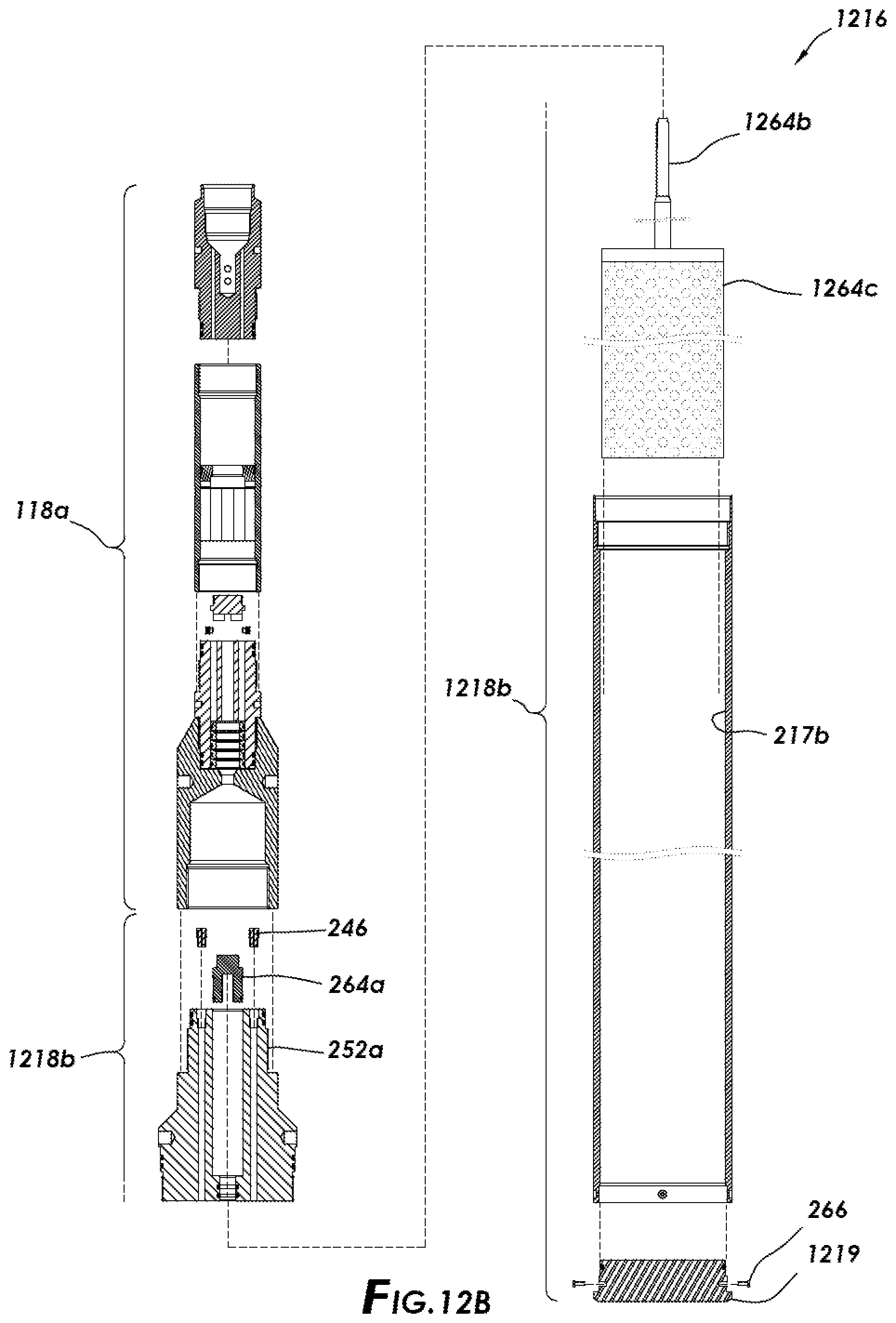
D00022

D00023

D00024

D00025

D00026

D00027

D00028

D00029

XML
uspto.report is an independent third-party trademark research tool that is not affiliated, endorsed, or sponsored by the United States Patent and Trademark Office (USPTO) or any other governmental organization. The information provided by uspto.report is based on publicly available data at the time of writing and is intended for informational purposes only.
While we strive to provide accurate and up-to-date information, we do not guarantee the accuracy, completeness, reliability, or suitability of the information displayed on this site. The use of this site is at your own risk. Any reliance you place on such information is therefore strictly at your own risk.
All official trademark data, including owner information, should be verified by visiting the official USPTO website at www.uspto.gov. This site is not intended to replace professional legal advice and should not be used as a substitute for consulting with a legal professional who is knowledgeable about trademark law.