Machine tool
Haueter , et al. April 5, 2
U.S. patent number 11,292,096 [Application Number 16/046,356] was granted by the patent office on 2022-04-05 for machine tool. This patent grant is currently assigned to GF Machining Solutions AG. The grantee listed for this patent is Liechti Engineering AG. Invention is credited to Ernst Haueter, Andreas Scheidegger, Christoph Urfer.


| United States Patent | 11,292,096 |
| Haueter , et al. | April 5, 2022 |
Machine tool
Abstract
The machine tool has a machine bed having a first horizontal linear guide and a second horizontal linear guide arranged at right angles to the first linear guide. On the first linear guide is arranged, in an axially displaceable manner, a workpiece clamping fixture, which is swivelable about a swivel axis oriented parallel to the second linear guide and is rotatable about a rotation axis oriented at right angles to the swivel axis. On the second linear guide a toque motor driven swivel arm is axially displaceable, the swivel axis of which is arranged parallel to the first linear guide and which on its free end bears a tool spindle, the axis of which is oriented parallel to the first linear guide.
| Inventors: | Haueter; Ernst (Bowil, CH), Urfer; Christoph (Thun, CH), Scheidegger; Andreas (Konolfingen, CH) | ||||||||||
|---|---|---|---|---|---|---|---|---|---|---|---|
| Applicant: |
|
||||||||||
| Assignee: | GF Machining Solutions AG
(N/A) |
||||||||||
| Family ID: | 1000006220059 | ||||||||||
| Appl. No.: | 16/046,356 | ||||||||||
| Filed: | July 26, 2018 |
Prior Publication Data
| Document Identifier | Publication Date | |
|---|---|---|
| US 20190030666 A1 | Jan 31, 2019 | |
Foreign Application Priority Data
| Jul 27, 2017 [EP] | 17183550 | |||
| Current U.S. Class: | 1/1 |
| Current CPC Class: | B23Q 1/4857 (20130101); B23Q 1/4852 (20130101); B23Q 1/015 (20130101); Y10T 483/1755 (20150115); Y10T 409/307952 (20150115); Y10T 409/305824 (20150115); Y10T 409/305768 (20150115); B23Q 3/15766 (20130101); Y10T 483/1891 (20150115); B23Q 11/0825 (20130101); B23Q 3/15724 (20161101); B23Q 2210/004 (20130101); B23Q 39/04 (20130101); Y10T 409/307896 (20150115) |
| Current International Class: | B23Q 1/01 (20060101); B23Q 1/48 (20060101); B23Q 11/08 (20060101); B23Q 3/157 (20060101); B23Q 39/04 (20060101) |
| Field of Search: | ;409/163,164,165,167,168,204,205,206,211,221,224,225,201,216 ;483/66,68 |
References Cited [Referenced By]
U.S. Patent Documents
| 3009398 | November 1961 | Newton et al. |
| 3379286 | April 1968 | Takagi |
| RE26393 | May 1968 | Daugherty |
| 4635329 | January 1987 | Holy |
| 4657453 | April 1987 | Goulot |
| 4984351 | January 1991 | Matsuyama |
| 5346343 | September 1994 | Babel |
| 5560415 | October 1996 | Geissler |
| 5584621 | December 1996 | Bertsche |
| 6120222 | September 2000 | Hiramoto |
| 6454636 | September 2002 | Iwabuchi |
| 7318693 | January 2008 | Hansch |
| 7909550 | March 2011 | Hsu |
| 8523500 | September 2013 | Yamaura |
| 8523746 | September 2013 | Haus |
| 2001/0006595 | July 2001 | Hogl |
| 2002/0051687 | May 2002 | Harami |
| 2002/0114678 | August 2002 | Klement |
| 2008/0078075 | April 2008 | Schrott |
| 2008/0175684 | July 2008 | Schmidt |
| 2009/0324145 | December 2009 | Wardle |
| 2010/0202848 | August 2010 | Tanizaki |
| 2011/0162805 | July 2011 | Cheng |
| 2013/0207331 | August 2013 | Jung |
| 2014/0187398 | July 2014 | Abeln |
| 2018/0104784 | April 2018 | Suzuki |
| 10061934 | Jun 2005 | DE | |||
| 10-2012-201736 | Jun 2013 | DE | |||
| 1 002 621 | May 2000 | EP | |||
| 1 595 639 | Nov 2005 | EP | |||
| 2 602 052 | Jun 2013 | EP | |||
| 2 202 769 | Oct 1988 | GB | |||
| 2013163259 | Aug 2013 | JP | |||
| WO-03-101663 | Dec 2003 | WO | |||
Assistant Examiner: Vitale; Michael
Attorney, Agent or Firm: Harness, Dickey & Pierce, P.L.C.
Claims
What is claimed is:
1. A machine tool comprising: a machine bed having a first horizontal linear guide and a second horizontal linear guide, a longitudinal axis of the second horizontal linear guide being arranged at a right angle to a longitudinal axis of the first horizontal linear guide; a workpiece clamping fixture arranged on the first horizontal linear guide in an axially displaceable manner, the workpiece clamping fixture is swivelable about a first swivel axis oriented parallel to the longitudinal axis of the second horizontal linear guide and is rotatable about a rotation axis oriented at a right angle to the first swivel axis; a swivel arm axially displaceable on the second horizontal linear guide, a second swivel axis of the swivel arm is arranged parallel to the longitudinal axis of the first horizontal linear guide; a tool spindle on a free end of the swivel arm, a spindle axis of the tool spindle is oriented parallel to the longitudinal axis of the first horizontal linear guide; and a torque motor having a rotor and a stator disposed on the second swivel axis of the swivel arm, the torque motor being configured to swivel the swivel arm about the second swivel axis; a linear motor configured to move the swivel arm linearly along the second horizontal linear guide; wherein the second swivel axis of the swivel arm is always in parallel to the spindle axis of the tool spindle; wherein the swivel arm is configured to vertically move the tool spindle; and wherein the linear motor and the torque motor are configured to simultaneously move to provide a combined circular motion of the second swivel axis and linear motion of the second swivel axis along the second horizontal linear guide.
2. The machine tool according to claim 1 wherein, for the swivel motion and the rotary motion of the workpiece clamping fixture, an additional torque motor is respectively present.
3. The machine tool according to claim 1 wherein on a side of the second horizontal linear guide facing the workpiece clamping fixture is arranged an X-Y protective cover having a driving plate in which is accommodated a pivot bearing surrounding a tool-side end of the tool spindle.
4. The machine tool according to claim 1 wherein on a side of the second horizontal linear guide facing towards the workpiece clamping fixture is arranged an angular or arcuate tool-holding chain magazine having an approximately horizontally arranged limb and an approximately vertically arranged limb, and at a free end of the approximately horizontal limb is arranged a tool changer.
5. The machine tool according to claim 1, further comprising: a slide bearing extending between the stator and the rotor in a direction parallel to the second swivel axis and extending around the torque motor, the slide bearing configured to provide oil damping.
6. The machine tool according to claim 5, wherein the rotor is an external rotor and the stator is an internal stator.
7. The machine tool according to claim 1, wherein the second swivel axis of the swivel arm is offset from the spindle axis of the tool spindle.
8. A machine tool comprising: a machine bed having a first horizontal linear guide and a second horizontal linear guide, a longitudinal axis of the second horizontal linear guide being arranged at a right angle to a longitudinal axis of the first horizontal linear guide; a workpiece clamping fixture arranged on the first horizontal linear guide in an axially displaceable manner, the workpiece clamping fixture is swivelable about a first swivel axis oriented parallel to the longitudinal axis of the second horizontal linear guide and is rotatable about a rotation axis oriented at a right angle to the first swivel axis; a swivel arm axially displaceable on the second horizontal linear guide, a second swivel axis of the swivel arm is arranged parallel to the longitudinal axis of the first horizontal linear guide; a tool spindle on a free end of the swivel arm, an axis of rotation of the tool spindle is oriented parallel to the longitudinal axis of the first horizontal linear guide, the axis of rotation of the tool spindle extends parallel to the second swivel axis of the swivel arm, and the swivel arm rotates about the second swivel axis to position the tool spindle; and a torque motor including a stator and a rotor, the torque motor is disposed on the second swivel axis of the swivel arm and is configured to swivel the swivel arm about the second swivel axis to position the tool spindle; wherein the second swivel axis of the swivel arm is offset from the axis of rotation of the tool spindle; wherein the second swivel axis of the swivel arm is always in parallel to the axis of rotation of the tool spindle; and wherein a linear motor and the torque motor are configured to simultaneously move to provide a combined circular motion of the second swivel axis and linear motion of the second swivel axis along the second horizontal linear guide.
9. The machine tool of claim 8, wherein the rotor is an external rotor and the stator is an internal stator.
10. The machine tool of claim 8, further comprising a slide bearing extending between the stator and the rotor in a direction parallel to the second swivel axis and extending around the torque motor.
11. The machine tool of claim 10, wherein the slide bearing is configured to provide oil damping.
12. A machine tool comprising: a machine bed having a first horizontal linear guide and a second horizontal linear guide, a longitudinal axis of the second horizontal linear guide being arranged at a right angle to a longitudinal axis of the first horizontal linear guide; a workpiece clamping fixture arranged on the first horizontal linear guide in an axially displaceable manner, the workpiece clamping fixture is swivelable about a first swivel axis oriented parallel to the longitudinal axis of the second horizontal linear guide and is rotatable about a rotation axis oriented at a right angle to the first swivel axis; a swivel arm axially displaceable on the second horizontal linear guide by a linear motor, a second swivel axis of the swivel arm is arranged parallel to the longitudinal axis of the first horizontal linear guide; a tool spindle on a free end of the swivel arm, an axis of rotation of the tool spindle is oriented parallel to the longitudinal axis of the first horizontal linear guide, the axis of rotation of the tool spindle extends parallel to the second swivel axis of the swivel arm, and the swivel arm rotates about the second swivel axis to position the tool spindle; and a torque motor including a stator and a rotor, the torque motor is disposed on the second swivel axis of the swivel arm and is configured to swivel the swivel arm about the second swivel axis to position the tool spindle; wherein the second swivel axis of the swivel arm is offset from the axis of rotation of the tool spindle; and wherein the linear motor and the torque motor are configured to simultaneously move to provide a combined circular motion of the second swivel axis and linear motion of the second swivel axis along the second horizontal linear guide.
Description
CROSS-REFERENCE TO RELATED APPLICATION
This application claims the benefit and priority of European Patent Application No. 17 183 550.7, filed Jul. 27, 2017, the entire disclosure of which is incorporated herein by reference.
BACKGROUND
Technical Field
The invention relates to a machine tool.
Related Art
Document EP1002621A1 shows a similarly constructed machine tool. The swivel motion of the swivel arm is in this machine produced by a spindle drive and a lever mechanism.
SUMMARY
Starting from this prior art, an aspect of the invention is to propose a machine tool which is of simpler construction and allows more rapid swivel motions of the swivel arm than the known machine.
This aspect is achieved according to the invention by the features described herein.
By virtue of the design according to the invention, the machine tool requires for the swivel motion of the swivel arm fewer moving parts and allows more rapid swivel motions than the known machine.
Particular embodiments of the invention are also described.
Another aspect of the invention relates to a swivel arm for a machine tool and achieves reduction of damping vibrations of the swivel arm which are caused, for instance, by the tool spindle disposed on its end.
BRIEF DESCRIPTION OF THE DRAWINGS
Illustrative embodiments of the invention are explained below with reference to the attached drawings, wherein:
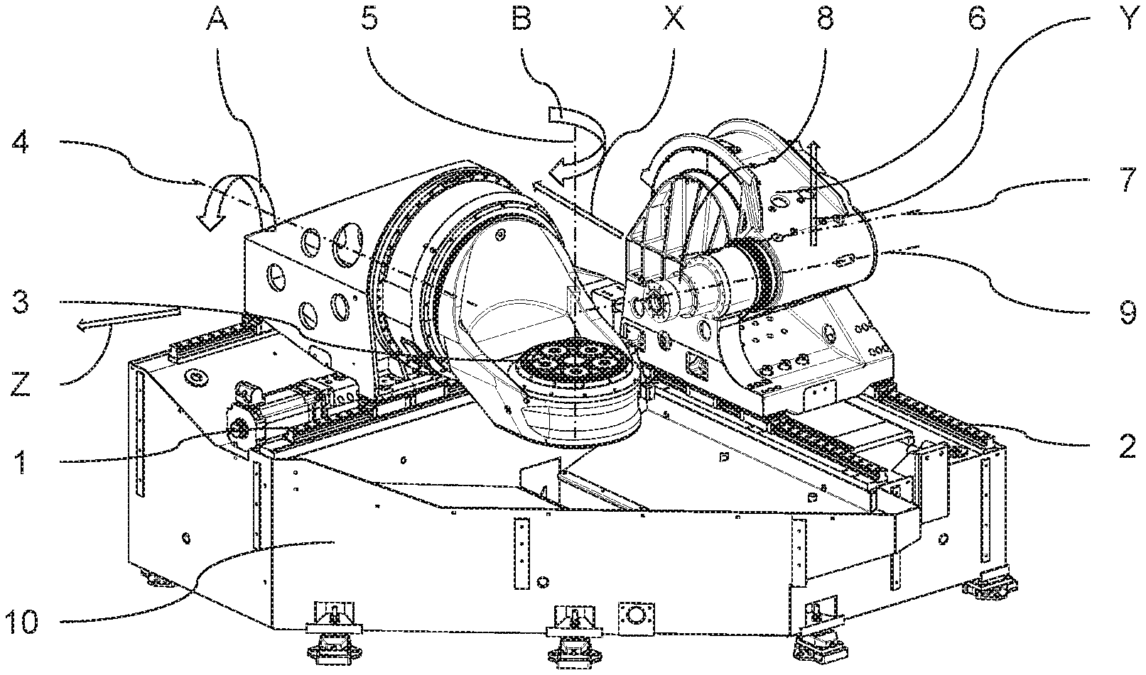
FIG. 1 shows a perspective view of a machine tool according to the invention;
FIG. 2 shows a similar view to FIG. 1 with X-Y protective walls and a tool-holding chain magazine; and
FIG. 3 shows a sectional view of the mounting and of the drive mechanism of the swivel arm.
DESCRIPTION OF EXEMPLARY EMBODIMENTS
FIG. 1 shows in a perspective view an illustrative embodiment of the machine tool according to the invention. This is particularly suitable for the machining of blade wheels for turbines, so-called "bladed discs", also referred to as "bliscs". On a machine bed 10 is arranged a first horizontal linear guide 1 and, at right angles thereto, a second horizontal linear guide 2. On the first linear guide 1, a workpiece clamping fixture 3 is arranged such that it is horizontally movable and is swivelable about a horizontal swivel axis 4. For the horizontal motion of the workpiece clamping fixture 3 on the first linear guide 1, a ball screw, for instance, is provided. Alternatively, the horizontal motion can be executed by means of a linear motor. Moreover, the workpiece clamping fixture 3 is rotatable about a rotation axis 5 oriented at right angles to its swivel axis 4. Disc-shaped blanks for blade wheels are supplied lying flat, for instance on pallets. The arrangement and design of the workpiece clamping fixture 3 allows these blanks to be clamped without being tilted, which is particularly advantageous in the case of large and heavy blanks.
On the second linear guide 2, a swivel arm 6 is arranged such that it is horizontally movable and is swivelable about a horizontal swivel axis 7, on the free end of which swivel arm is arranged a tool spindle 8. The horizontal motions of the swivel arm 6 on the second linear guide 2 are preferably executed by a linear motor. The axis 9 of the tool spindle is oriented parallel to the swivel axis 7. The machine tool according to the invention is thus a five-axis machine having the translatory axes X, Y and Z and the rotatory axes A and B. A particularity is here that, for a pure displacement of the tool along the Y-axis, a combined circular motion of the tool spindle 8 and linear motion of the swivel axis 7 along the linear guide 2 is necessary.
A particular advantage of this construction consists in the fact that the center of gravity of the entire unit which is movable on the second linear guide 2 is located vertically only a little above the second linear guide 2 and moves only a little upwards when the tool spindle 8 is transported into its uppermost position. This in contrast to machine tools of different construction, such as, for instance, the machine according to EP1509360, in which a tool spindle is likewise disposed on a swivel arm, wherein, however, the swivel arm is raised, together with its swivel drive, along a vertical linear guide in order to bring the tool spindle into an upper position. A high center of gravity promotes the occurrence of undesirable vibrations. The direct driving of the swivel arm 6 by a torque motor disposed on the swivel axis 7 allows rapid and precise motions of the tool spindle 8.
FIG. 2 shows the same machine as FIG. 1, yet with additional sub-assemblies, of which two are described in greater detail below. Two X-Y protective covers 11 and 12 separate the working space from the other regions of the machine tool, in particular the linear guides 1 and 2, in order to keep chips, and also coolant and lubricant, in the working space. These X-Y protective covers can be of known construction, having a driving plate 13 and plate fins operatively connected thereto, for instance as described in EP19861324A1. In the machine according to the invention, having the swivel arm 6, the problem now exists that that part of the tool spindle 8 which passes through the driving plate 13, with the swiveling of the swivel arm 6, inevitably in the driving plate 13 executes a rotary motion. Therefore the tool spindle 8 cannot be connected directly to the driving plate 8, but rather with the interposition of a pivot bearing 14.
A further sub-assembly, which is visible in FIG. 2, is a tool-holding chain magazine 15, which is of angular or arcuate configuration and is configured such that a limb 16 ends with an at least approximately horizontally oriented end in the top of the work region, and a limb 17 ends with an at least approximately vertically oriented end in a region, facing away from the working area, behind the first linear guide. On the end region of the limb 16 is arranged a tool changer 18, which is reachable by the tool spindle 8 along a short path. The end region of the limb 17 is configured for the loading and emptying of the tool-holding chain magazine 15 and is easily reachable by an operator.
FIG. 3 shows in a sectioned view a detail of the mounting of the swivel arm 6. The latter is driven in the present example by means of an external-rotor torque motor. A torque motor stator denoted by 19 has a stator part 20 connected in a rotationally secure manner thereto. A torque motor rotor 21 is additionally supported on the stator part 20 by an oil-lubricated slide bearing 22. The slide bearing 22 has, by virtue of its oil film, a vibration-damping effect (squeeze film damping).
* * * * *
D00000
D00001
D00002
XML
uspto.report is an independent third-party trademark research tool that is not affiliated, endorsed, or sponsored by the United States Patent and Trademark Office (USPTO) or any other governmental organization. The information provided by uspto.report is based on publicly available data at the time of writing and is intended for informational purposes only.
While we strive to provide accurate and up-to-date information, we do not guarantee the accuracy, completeness, reliability, or suitability of the information displayed on this site. The use of this site is at your own risk. Any reliance you place on such information is therefore strictly at your own risk.
All official trademark data, including owner information, should be verified by visiting the official USPTO website at www.uspto.gov. This site is not intended to replace professional legal advice and should not be used as a substitute for consulting with a legal professional who is knowledgeable about trademark law.