Material-removal systems, cutting tools therefor, and related methods
Myers , et al. June 1, 2
U.S. patent number 11,021,953 [Application Number 16/527,620] was granted by the patent office on 2021-06-01 for material-removal systems, cutting tools therefor, and related methods. This patent grant is currently assigned to APERGY BMCS ACQUISITION CORPORATION. The grantee listed for this patent is APERGY BMCS ACQUISITION CORPORATION. Invention is credited to Grant K. Daniels, Russell R. Myers, Heath C. Whittier.


| United States Patent | 11,021,953 |
| Myers , et al. | June 1, 2021 |
Material-removal systems, cutting tools therefor, and related methods
Abstract
Embodiments described herein relate to material-removal systems and cutting tools that may be used in the material-removal systems. More specifically, for example, the material-removal systems, and particularly the cutting tools thereof, may engage and fail target material. In some instances, the material-removal systems may be used in mining operations.
| Inventors: | Myers; Russell R. (Salem, UT), Daniels; Grant K. (Spanish Fork, UT), Whittier; Heath C. (Orem, UT) | ||||||||||
|---|---|---|---|---|---|---|---|---|---|---|---|
| Applicant: |
|
||||||||||
| Assignee: | APERGY BMCS ACQUISITION
CORPORATION (Orem, UT) |
||||||||||
| Family ID: | 1000004219310 | ||||||||||
| Appl. No.: | 16/527,620 | ||||||||||
| Filed: | July 31, 2019 |
Related U.S. Patent Documents
| Application Number | Filing Date | Patent Number | Issue Date | ||
|---|---|---|---|---|---|
| 14811699 | Jul 28, 2015 | 10408057 | |||
| 62030525 | Jul 29, 2014 | ||||
| Current U.S. Class: | 1/1 |
| Current CPC Class: | E21C 35/183 (20130101); E21C 35/19 (20130101); E21C 25/06 (20130101); E21C 35/1835 (20200501); E21C 35/1837 (20200501); E21C 35/1831 (20200501) |
| Current International Class: | E21C 35/183 (20060101); E21C 35/19 (20060101); E21C 25/06 (20060101) |
References Cited [Referenced By]
U.S. Patent Documents
| 2665893 | January 1954 | Ball |
| 3342532 | September 1967 | Krekeler et al. |
| 3544166 | December 1970 | Proctor |
| 3671075 | June 1972 | Bland et al. |
| 3695726 | October 1972 | Krekeler |
| 3751114 | August 1973 | Davis |
| 3785021 | January 1974 | Norgren et al. |
| 3841708 | October 1974 | Kniff et al. |
| D238243 | December 1975 | Polivka |
| 3958832 | May 1976 | Sigott |
| 4006936 | February 1977 | Crabiel |
| 4083644 | April 1978 | Friedline et al. |
| 4140189 | February 1979 | Garner |
| 4193638 | March 1980 | Heckenhauer |
| 4200159 | April 1980 | Jurgens et al. |
| 4299424 | November 1981 | LeBegue et al. |
| 4303136 | December 1981 | Ball |
| 4335921 | June 1982 | Swisher et al. |
| 4337980 | July 1982 | Krekeler et al. |
| 4340325 | July 1982 | Gowanlock et al. |
| D270059 | August 1983 | Wilkins |
| D271497 | November 1983 | Green |
| 4484644 | November 1984 | Cook et al. |
| 4580930 | April 1986 | Zinner et al. |
| 4605343 | August 1986 | Hibbs, Jr. et al. |
| 4655508 | April 1987 | Tomlinson |
| 4678237 | July 1987 | Collin |
| 4679858 | July 1987 | Tank |
| D296107 | June 1988 | Andersson |
| 4765687 | August 1988 | Parrott |
| 4784023 | November 1988 | Dennis et al. |
| 4787466 | November 1988 | Tomlinson et al. |
| 4836178 | June 1989 | Tomlinson |
| 4842337 | June 1989 | Southern |
| 4850649 | July 1989 | Beach et al. |
| 4880278 | November 1989 | Tomlinson |
| 4902073 | February 1990 | Tomlinson et al. |
| D307279 | April 1990 | Vincent |
| 4913125 | April 1990 | Bunting et al. |
| D311747 | October 1990 | Mihic |
| 5007685 | April 1991 | Beach et al. |
| 5060739 | October 1991 | Griffin et al. |
| 5090491 | February 1992 | Tibbitts et al. |
| 5318351 | June 1994 | Walker |
| 5378050 | January 1995 | Kammerer et al. |
| 5417475 | May 1995 | Graham et al. |
| 5431239 | July 1995 | Tibbitts et al. |
| 5605382 | February 1997 | Massa et al. |
| 5649604 | July 1997 | Fuller et al. |
| 5690393 | November 1997 | Massa et al. |
| 5881830 | March 1999 | Cooley |
| 5906245 | May 1999 | Tibbitts et al. |
| 6089123 | July 2000 | Chow et al. |
| 6213931 | April 2001 | Twardowski et al. |
| 6283844 | September 2001 | Tank |
| 6485104 | November 2002 | Keller et al. |
| 6779850 | August 2004 | Schibeci et al. |
| 7108212 | September 2006 | Latham |
| D558802 | January 2008 | Nicholas |
| D616003 | May 2010 | Ueda et al. |
| 7866418 | January 2011 | Bertagnolli et al. |
| 7998573 | August 2011 | Qian et al. |
| 8034136 | October 2011 | Sani |
| 8047260 | November 2011 | Uno et al. |
| 8079785 | December 2011 | Nicholas |
| 8236074 | August 2012 | Bertagnolli et al. |
| D666640 | September 2012 | Cox et al. |
| 8567533 | October 2013 | Myers et al. |
| 8672415 | May 2014 | Neilson et al. |
| 8727044 | May 2014 | Qian et al. |
| 8789894 | July 2014 | Claesson et al. |
| 9017438 | April 2015 | Miess et al. |
| 9027675 | May 2015 | Jones et al. |
| 9028008 | May 2015 | Bookhamer et al. |
| 9238893 | January 2016 | Latham et al. |
| 9272392 | March 2016 | Mukhopadhyay et al. |
| 9272814 | March 2016 | Carver et al. |
| 9303511 | April 2016 | George et al. |
| 9382794 | July 2016 | Latham et al. |
| 9434091 | September 2016 | Burton et al. |
| 9487847 | November 2016 | Mukhopadhyay et al. |
| 9593577 | March 2017 | Lachmann et al. |
| D809031 | January 2018 | Burton |
| 10018041 | July 2018 | Wachsmann et al. |
| 10316660 | June 2019 | Burton et al. |
| 10323514 | June 2019 | Burton et al. |
| 10414069 | September 2019 | Miess et al. |
| 2001/0040053 | November 2001 | Beuershausen et al. |
| 2002/0153175 | October 2002 | Ojanen et al. |
| 2003/0234569 | December 2003 | Dawood et al. |
| 2005/0082898 | April 2005 | Keller et al. |
| 2006/0033379 | February 2006 | Frear et al. |
| 2006/0087169 | April 2006 | Hesse et al. |
| 2007/0090679 | April 2007 | Ojanen et al. |
| 2008/0030065 | February 2008 | Frear et al. |
| 2008/0035383 | February 2008 | Hall et al. |
| 2008/0036280 | February 2008 | Hall et al. |
| 2008/0202819 | August 2008 | Fader |
| 2008/0250724 | October 2008 | Hall et al. |
| 2008/0309146 | December 2008 | Hall et al. |
| 2009/0256413 | October 2009 | Majagi |
| 2010/0052406 | March 2010 | Beach et al. |
| 2010/0194176 | August 2010 | Lucek et al. |
| 2010/0244545 | September 2010 | Hall et al. |
| 2010/0326741 | December 2010 | Patel |
| 2011/0132667 | June 2011 | Lai et al. |
| 2011/0148178 | June 2011 | Lehnert et al. |
| 2011/0233987 | September 2011 | Maushart et al. |
| 2011/0266070 | November 2011 | Scott et al. |
| 2012/0043138 | February 2012 | Myers et al. |
| 2012/0138370 | June 2012 | Mukhopadhyay |
| 2012/0160573 | June 2012 | Myers |
| 2012/0175939 | July 2012 | O'Neill et al. |
| 2012/0274123 | November 2012 | Ball |
| 2012/0279786 | November 2012 | Cox |
| 2013/0052481 | February 2013 | Konyashin |
| 2013/0092451 | April 2013 | Mukhopadhyay et al. |
| 2013/0092452 | April 2013 | Mukhopadhyay et al. |
| 2013/0322975 | December 2013 | Tan et al. |
| 2013/0341999 | December 2013 | Hall et al. |
| 2014/0110991 | April 2014 | Sollami |
| 2014/0175853 | June 2014 | Warren |
| 2014/0225418 | August 2014 | Lachmann et al. |
| 2014/0240634 | August 2014 | Matsuzaki |
| 2014/0339879 | November 2014 | Burton et al. |
| 2014/0339883 | November 2014 | Burton et al. |
| 2014/0368022 | December 2014 | Torres Delgado et al. |
| 2015/0035342 | February 2015 | Jonker et al. |
| 2015/0114727 | April 2015 | Heuser |
| 2015/0176408 | June 2015 | Latham |
| 2015/0176409 | June 2015 | Latham |
| 2015/0240635 | August 2015 | Lachmann et al. |
| 2015/0314483 | November 2015 | Miess et al. |
| 2016/0102550 | April 2016 | Swope et al. |
| 2016/0273356 | September 2016 | Ojanen et al. |
| 2016/0332269 | November 2016 | Provins et al. |
| 2013101370 | Nov 2013 | AU | |||
| 102108866 | Jun 2011 | CN | |||
| 202073564 | Dec 2011 | CN | |||
| 203081445 | Jul 2013 | CN | |||
| 1481278 | Jul 1977 | GB | |||
| 2170843 | Aug 1986 | GB | |||
| 2177144 | Jan 1987 | GB | |||
| 2193740 | Feb 1988 | GB | |||
| 2010083015 | Jul 2010 | WO | |||
| 2012130870 | Oct 2012 | WO | |||
| 2016071001 | May 2016 | WO | |||
Other References
|
Advisory Action for U.S. Appl. No. 14/266,437 dated Mar. 24, 2017. cited by applicant . Advisory Action for U.S. Appl. No. 14/275,574 dated Mar. 9, 2017. cited by applicant . Advisory Action for U.S. Appl. No. 14/811,699 dated Oct. 22, 2018. cited by applicant . Advisory Action for U.S. Appl. No. 15/266,355 dated Oct. 11, 2018. cited by applicant . Final Office Action for U.S. Appl. No. 14/266,437 dated Dec. 12, 2016. cited by applicant . Final Office Action for U.S. Appl. No. 14/266,437 dated Nov. 15, 2017. cited by applicant . Final Office Action for U.S. Appl. No. 14/266,437 dated Sep. 18, 2018. cited by applicant . Final Office Action for U.S. Appl. No. 14/273,360 dated Mar. 7, 2016. cited by applicant . Final Office Action for U.S. Appl. No. 14/275,574 dated Nov. 29, 2016. cited by applicant . Final Office Action for U.S. Appl. No. 14/811,699 dated Jul. 10, 2018. cited by applicant . Final Office Action for U.S. Application No. 15/238,486 dated Feb. 26, 2018. cited by applicant . Final Office Action for U.S. Appl. No. 15/266,355 dated Jul. 25, 2018. cited by applicant . Final Office Action for U.S. Appl. No. 15/266,355 dated May 9, 2019. cited by applicant . International Search Report and Written Opinion for International Application No. PCT/US2015/027830 dated Jul. 14, 2015. cited by applicant . International Search Report and Written Opinion from International Application No. PCT/US2014/037381 dated Oct. 30, 2014. cited by applicant . International Search Report and Written Opinion from International Application No. PCT/US2014/037708 dated Oct. 30, 2014. cited by applicant . Issue Notification for U.S. Appl. No. 14/273,360 dated Aug. 17, 2016. cited by applicant . Issue Notification for U.S. Appl. No. 14/275,574 dated May 29, 2019. cited by applicant . Issue Notification for U.S. Appl. No. 15/238,486 dated May 22, 2019. cited by applicant . Issue Notification for U.S. Appl. No. 29/540,584 dated Sep. 14, 2017. cited by applicant . Issue Notification for U.S. Appl. No. 29/540,597 dated Sep. 6, 2017. cited by applicant . Issue Notification for U.S. Appl. No. 29/555,279 dated Jan. 10, 2018. cited by applicant . Issue Notification for U.S. Appl. No. 29/555,281 dated Aug. 29, 2018. cited by applicant . Non-Final Office Action for U.S. Appl. No. 14/266,437 dated Jun. 9, 2016. cited by applicant . Non-Final Office Action for U.S. Appl. No. 14/266,437 dated Apr. 21, 2017. cited by applicant . Non-Final Office Action for U.S. Appl. No. 14/266,437 dated Jan. 8, 2019. cited by applicant . Non-Final Office Action for U.S. Appl. No. 14/266,437 dated Mar. 28, 2018. cited by applicant . Non-Final Office Action for U.S. Appl. No. 14/273,360 dated Oct. 22, 2015. cited by applicant . Non-Final Office Action for U.S. Appl. No. 14/275,574 dated Apr. 7, 2017. cited by applicant . Non-Final Office Action for U.S. Appl. No. 14/811,699 dated Jan. 4, 2019. cited by applicant . Non-Final Office Action for U.S. Appl. No. 14/811,699 dated Nov. 29, 2017. cited by applicant . Non-Final Office Action for U.S. Appl. No. 15/238,486 dated Aug. 17, 2017. cited by applicant . Non-Final Office Action for U.S. Appl. No. 15/266,355 dated Jan. 8, 2018. cited by applicant . Non-Final Office Action for U.S. Appl. No. 15/266,355 dated Nov. 29, 2018. cited by applicant . Non-Final Office Action for U.S. Appl. No. 16/406,673 dated Jun. 27, 2019. cited by applicant . Non-Final Office Action for U.S. Appl. No. 29/555,279 dated Mar. 24, 2017. cited by applicant . Notice of Allowance for U.S. Appl. No. 14/273,360 dated May 18, 2016. cited by applicant . Notice of Allowance for U.S. Appl. No. 14/266,437 dated May 2, 2019. cited by applicant . Notice of Allowance for U.S. Appl. No. 14/275,574 dated Feb. 12, 2019. cited by applicant . Notice of Allowance for U.S. Appl. No. 14/275,574 dated Jan. 24, 2018. cited by applicant . Notice of Allowance for U.S. Appl. No. 14/275,574 dated Jun. 15, 2018. cited by applicant . Notice of Allowance for U.S. Appl. No. 14/275,574 dated Oct. 11, 2018. cited by applicant . Notice of Allowance for U.S. Appl. No. 14/275,574 dated Sep. 26, 2017. cited by applicant . Notice of Allowance for U.S. Appl. No. 14/811,699 dated May 1, 2019. cited by applicant . Notice of Allowance for U.S. Appl. No. 15/238,486 dated Jan. 28, 2019. cited by applicant . Notice of Allowance for U.S. Appl. No. 15/238,486 dated Jun. 20, 2018. cited by applicant . Notice of Allowance for U.S. Appl. No. 15/238,486 dated Oct. 10, 2018. cited by applicant . Notice of Allowance for U.S. Appl. No. 29/540,584 dated May 8, 2017. cited by applicant . Notice of Allowance for U.S. Appl. No. 29/540,597 dated May 8, 2017. cited by applicant . Notice of Allowance for U.S. Appl. No. 29/555,269 dated Apr. 6, 2017. cited by applicant . Notice of Allowance for U.S. Appl. No. 29/555,279 dated Aug. 31, 2017. cited by applicant . Notice of Allowance for U.S. Appl. No. 29/555,281 dated Apr. 12, 2017. cited by applicant . Notice of Allowance for U.S. Appl. No. 29/555,281 dated Jan. 4, 2018. cited by applicant . Notice of Allowance for U.S. Appl. No. 29/555,281 dated May 16, 2018. cited by applicant . Notice of Allowance for U.S. Appl. No. 29/660,512 dated Apr. 25, 2019. cited by applicant . Restriction Requirement for U.S. Appl. No. 14/273,360 dated Jun. 12, 2015. cited by applicant . Roepke et al.; "Drag Bit Cutting Characteristics Using Sintered Diamond Inserts" Report of Investigations 8802; Bureau of Mines Report of Investigations/ 1983; (1983) 35 pages. cited by applicant . Supplemental Notice of Allowance for U.S. Appl. No. 14/273,360 dated Aug. 10, 2016. cited by applicant . Supplemental Notice of Allowance for U.S. Appl. No. 14/275,574 dated May 21, 2019. cited by applicant . Supplemental Notice of Allowance for U.S. Appl. No. 14/275,574 dated Oct. 31, 2018. cited by applicant . Supplemental Notice of Allowance for U.S. Appl. No. 15/238,486 dated Jun. 27, 2018. cited by applicant . Supplemental Notice of Allowance for U.S. Appl. No. 29/540,584 dated Sep. 7, 2017. cited by applicant . Supplemental Notice of Allowance for U.S. Appl. No. 29/540,597 dated Aug. 25, 2017. cited by applicant . Supplemental Notice of Allowance for U.S. Appl. No. 29/540,597 dated Jun. 1, 2017. cited by applicant . Supplemental Notice of Allowance for U.S. Appl. No. 29/555,269 dated Apr. 28, 2017. cited by applicant . Supplemental Notice of Allowance for U.S. Appl. No. 29/555,279 dated Jan. 2, 2018. cited by applicant . Supplemental Notice of Allowance for U.S. Appl. No. 29/555,281 dated Feb. 9, 2018. cited by applicant . Supplemental Notice of Allowance for U.S. Appl. No. 29/555,281 dated Jun. 12, 2017. cited by applicant . Supplemental Notice of Allowance for U.S. Appl. No. 29/555,281 dated Jun. 4, 2018. cited by applicant . U.S. Appl. No. 12/961,787, filed Dec. 7, 2010. cited by applicant . U.S. Appl. No. 13/027,954, filed Feb. 15, 2011. cited by applicant . U.S. Appl. No. 13/070,636, filed Mar. 24, 2011. cited by applicant . U.S. Appl. No. 13/100,388, filed May 4, 2011. cited by applicant . U.S. Appl. No. 13/275,372, filed Oct. 18, 2011. cited by applicant . U.S. Appl. No. 13/648,913, filed Oct. 10, 2012. cited by applicant . U.S. Appl. No. 13/765,027, filed Feb. 12, 2013. cited by applicant . U.S. Appl. No. 13/795,027, filed Mar. 12, 2013. cited by applicant . U.S. Appl. No. 14/266,437, filed Apr. 30, 2014. cited by applicant . U.S. Appl. No. 14/273,360, filed Mar. 7, 2016. cited by applicant . U.S. Appl. No. 14/273,360, filed May 8, 2014. cited by applicant . U.S. Appl. No. 14/275,574, filed May 12, 2014. cited by applicant . U.S. Appl. No. 14/811,699, filed Jul. 28, 2015. cited by applicant . U.S. Appl. No. 15/238,486, filed Aug. 16, 2016. cited by applicant . U.S. Appl. No. 16/406,673, filed May 8, 2019. cited by applicant . U.S. Appl. No. 29/540,584, filed Sep. 25, 2015. cited by applicant . U.S. Appl. No. 29/555,269, filed Feb. 19, 2016. cited by applicant . U.S. Appl. No. 29/555,279, filed Feb. 19, 2016. cited by applicant . U.S. Appl. No. 29/555,281, filed Feb. 19, 2016. cited by applicant . U.S. Appl. No. 61/824,007, filed May 16, 2013. cited by applicant . U.S. Appl. No. 61/824,022, filed May 16, 2013. cited by applicant . U.S. Appl. No. 62/030,525, filed Jul. 29, 2014. cited by applicant . U.S. Appl. No. 62/232,732, filed Sep. 25, 2015. cited by applicant . Final Office Action for U.S. Appl. No. 16/406,673, dated Dec. 26, 2019. cited by applicant . Issue Notification for U.S. Appl. No. 14/266,437 dated Aug. 28, 2019. cited by applicant . Issue Notification for U.S. Appl. No. 14/811,699 dated Aug. 21, 2019. cited by applicant . Issue Notification for U.S. Appl. No. 29/660,512 dated Aug. 28, 2019. cited by applicant . Non-Final Office Action for U.S. Appl. No. 16/526,387, dated Oct. 4, 2019. cited by applicant . Notice of Allowance for U.S. Appl. No. 15/266,355 dated Sep. 24, 2019. cited by applicant . Supplemental Notice of Allowability for U.S. Appl. No. 14/266,437 dated Aug. 19, 2019. cited by applicant . Advisory Action for U.S. Appl. No. 16/406,673 dated Mar. 6, 2020. cited by applicant . Final Office Action for U.S. Appl. No. 16/526,387 dated Apr. 22, 2020. cited by applicant . Issue Notification for U.S. Appl. No. 15/266,355 dated Apr. 22, 2020. cited by applicant . Non-Final Office Action for U.S. Appl. No. 16/406,673 dated Apr. 3, 2020. cited by applicant . Notice of Allowance for U.S. Appl. No. 15/266,355 dated Jan. 9, 2020. cited by applicant . Advisory Action for U.S. Appl. No. 16/526,387 dated Aug. 10, 2020. cited by applicant . Non-Final Office Action for U.S. Appl. No. 16/393,603 dated Aug. 6, 2020. cited by applicant . Non-Final Office Action for U.S. Appl. No. 16/526,387 dated Sep. 24, 2020. cited by applicant . Notice of Allowance for U.S. Appl. No. 16/406,673 dated Sep. 23, 2020. cited by applicant . Notice of Allowance for U.S. Appl. No. 16/526,387 dated Mar. 25, 2021. cited by applicant . Supplemental Notice of Allowance for U.S. Appl. No. 16/406,673 dated Apr. 27, 2021. cited by applicant. |
Primary Examiner: Kreck; Janine M
Assistant Examiner: Goodwin; Michael A
Attorney, Agent or Firm: Dorsey & Whitney LLP
Parent Case Text
CROSS-REFERENCE TO RELATED APPLICATIONS
This application is a continuation of U.S. application Ser. No. 14/811,699 filed on 28 Jul. 2015, which claims priority to U.S. Provisional Application No. 62/030,525 filed on 29 Jul. 2014, the disclosure of each of which is incorporated herein, in its entirety, by this reference.
Claims
What is claimed is:
1. A material-removal system, comprising: a movable cutting head; and a plurality of cutting tools mounted on the cutting head, each of the plurality of cutting tools including: a tool body having a front surface, a front slanted surface extending from the front surface, a back surface; a pocket formed in the tool body between the front slanted surface and the back surface, the pocket comprising a first surface and a second surface; and a cutting element attached to the tool body to secure the cutting element at least partially within the pocket, the cutting element having a substrate and a superhard table that includes a substantially planar working surface offset from the front slanted surface and oriented at a back rake angle with respect to a longitudinal axis of the tool body and a side rake angle, the substrate including a back surface opposite to the superhard table; wherein the first surface extends from the front slanted surface, is shaped complementary to a portion of the substrate, and is adjacent to only a portion of a side surface of the substrate, and the second surface extends from the back surface of the tool body and is adjacent to the back surface of the substrate.
2. The material-removal system of claim 1, wherein at least one of the plurality of cutting tools has a different side rake angle than other cutting tools of the plurality of cutting tools.
3. The material-removal system of claim 2, wherein the cutting element of a first cutting tool of the plurality of cutting tools has a larger side rake angle than the cutting element of a second cutting tool of the plurality of cutting tools, and the first cutting tool is located closer to a rotation axis of the movable cutting head than the second cutting tool.
4. The material-removal system of claim 1, wherein at least some of the cutting elements of the plurality of cutting tools include a nonplanar interface between the superhard table and the substrate thereof.
5. The material-removal system of claim 4, wherein the superhard table and the substrate include one or more complementary grooves and protrusions that form the nonplanar interface therebetween.
6. The material-removal system of claim 1, wherein at least some of the cutting elements of the plurality of cutting tools include a chamfer at least partially surrounding the substantially planar working surface.
7. The material-removal system of claim 6, wherein the superhard table of a first cutting tool of the plurality of cutting tools has a larger chamfer than the superhard table of a second cutting tool of the plurality of cutting tools, and the first cutting tool is located closer to a rotation axis of the movable cutting head than the second cutting tool.
8. The material-removal system of claim 1, wherein one or more of the back rake angle or side rake angle is from 15 degrees to 20 degrees and the superhard table has a greater thickness on a first side than a second side to form the back rake angle and the side rake angle.
9. The material-removal system of claim 1, wherein the back rake angle is 15 degrees to 20 degrees.
10. The material-removal system of claim 1, wherein the back rake angle is a negative back rake angle.
11. The material-removal system of claim 1, wherein the side rake angle is 15 degrees to 20 degrees.
12. The material-removal system of claim 1, wherein the substantially planar working surface has a trapezoidal shape.
13. The material-removal system of claim 1, wherein: the second surface is substantially parallel to the substantially planar working surface; the substrate of each of the cutting elements extends from the pocket past the front slanted surface; and the tool body of each cutting tool of the plurality of cutting tools includes: an elongated portion having a width substantially equal to a width of the cutting element; and a base portion having a width greater than the width of the elongated portion, the base portion being configured to secure the cutting tool to the movable cutting head.
14. A method of removing material, the method comprising: moving a plurality of cutting tools about a rotation axis, each of the plurality of cutting tools includes a tool body and a cutting element, the tool body of each of the plurality of cutting tools having a front surface, a front slanted surface extending from the front surface, a back surface, a pocket formed in the tool body between the front slanted surface and the back surface, the pocket comprising a first surface and a second surface, the cutting element of each of the plurality cutting tools being secured to the tool body at least partially within the pocket and including a substrate having a back surface, a superhard table opposite to the back surface of the substrate and having a working surface offset from the front slanted surface and oriented at a back rake angle with respect to a longitudinal axis of the tool body and a side rake angle, wherein the first surface extends from the front slanted surface, is shaped complementary to a portion of the substrate, and is adjacent to only a portion of a side surface of the substrate, and the second surface extends from the back surface of the tool body and is adjacent to the back surface of the substrate; advancing the plurality of cutting tools toward a target material; and engaging at least the working surfaces of the cutting tools with the target material, thereby failing at least some of the target material while having the working surfaces of the cutting tools oriented at the back rake angle and the side rake angle.
15. The method of claim 14, wherein at least two of the plurality of cutting tools are positioned at different positions.
16. The method of claim 14, wherein the back rake angle is a positive back rake angle.
17. The method of claim 14, wherein the back rake angle is a negative back rake angle.
18. The method of claim 14, wherein a first cutting tool of the plurality of cutting tools has a larger side rake angle than a second cutting tool of the plurality of cutting tools, and the first cutting tool is located closer to a rotation axis than the second cutting tool.
19. The method of claim 14, wherein the side rake angle of one or more cutting tools opens away from the rotation axis.
20. The method of claim 14, wherein the superhard table of a first cutting tool of the plurality of cutting tools has a larger chamfer than the superhard table of a second cutting tool of the plurality of cutting tools, and the first cutting tool is located closer to a rotation axis than the second cutting tool.
21. A material-removal system, comprising: a cutting head rotatable about a rotation axis; and a plurality of cutting tools mounted on the cutting head, at least two of the plurality of cutting tools being positioned at different radial locations relative to the rotation axis of the cutting head, and each of the plurality of cutting tools including: a tool body having a front surface, a front slanted surface extending from the front surface, a back surface, a pocket formed in the tool body between the front slanted surface and the back surface, the pocket comprising a first surface and a second surface; and a cutting element attached to the tool body to secure the cutting element at least partially within the pocket, the cutting element including a substrate and a polycrystalline diamond table having a substantially planar working surface offset from the front slanted surface and oriented at a back rake angle of 15 degrees to 20 degrees with respect to a longitudinal axis of the tool body and a side rake angle of 15 degrees to 20 degrees, the substrate including a back surface opposite to the superhard table; wherein the first surface extends from the front slanted surface, is shaped complementary to a portion of the substrate, and is adjacent to only a portion of a side surface of the substrate, and the second surface extends from the back surface of the tool body and is adjacent to the back surface of the substrate.
22. The material-removal system of claim 21, wherein the back rake angle is a negative back rake angle or a positive back rake angle.
23. The material-removal system of claim 21, wherein side rake angle is a negative side rake angle or a positive side rake angle.
24. The material-removal system of claim 21, wherein at least one of the plurality of cutting tools has a different side rake angle than other cutting tools of the plurality of cutting tools.
25. The material-removal system of claim 21, wherein the cutting element of a first cutting tool of the plurality of cutting tools has a larger side rake angle than the cutting element of a second cutting tool of the plurality of cutting tools, and the first cutting tool is located closer to the rotation axis than the second cutting tool.
26. The material-removal system of claim 21, wherein the polycrystalline diamond table of a first cutting tool of the plurality of cutting tools has a larger chamfer than the polycrystalline diamond table of a second cutting tool of the plurality of cutting tools, and the first cutting tool is located closer to the rotation axis than the second cutting tool.
27. The material-removal system of claim 21, wherein at least some of the polycrystalline diamond tables of the plurality of cutting tools include a chamfer at least partially surrounding the substantially planar working surface.
Description
BACKGROUND
Material-removal systems, such as mining machines, commonly use cutting tools or picks that engage and cut into target material. For example, cutting tools may be mounted on a rotatable mining head of the mining machine. While the mining head rotates, the mining machine and/or the mining head thereof may be advanced toward and into the target material. Hence, the cutting tools may engage, cut, or otherwise fail the target material as the mining head advances into the target material. Subsequently, the failed target material may be recovered or removed from its location, such as from a mine.
Particular target material may vary from one mining application to another. For example, mining machines may be used to fail and recover Trona or similar minerals and materials. In any event, operation of the mining machines typically results in wear of the cutting tools, which may lead to reduced useful life and reduced productivity as well as failure thereof, among other things.
Therefore, manufacturers and users continue to seek improved cutting tools and material-removal systems to extend the useful life thereof.
SUMMARY
Embodiments described herein relate to material-removal systems and cutting tools that may be used in the material-removal systems. More specifically, for example, the material-removal systems, and particularly the cutting tools thereof, may engage and fail target material. In some instances, the material-removal systems may be used in mining operations. Hence, the material-removal systems may mine the target material. In other words, For example, the material-removal systems may fail and remove or recover the failed target material (e.g., Trona).
At least one embodiment includes a material-removal system, which has a movable cutting head. The material-removal system includes a plurality of cutting tools mounted on the cutting head. Each of the plurality of cutting tools includes a tool body and a cutting element attached to the tool body. Each of the cutting elements has a substrate bonded to superhard table that includes a substantially planar working surface that is oriented at a back rake angle and a side rake angle. At least two of the plurality of cutting tools are positioned at different locations on the cutting head.
Embodiments also include a method of removing material. The method includes moving a plurality of cutting tools about a rotation axis. At least two of the plurality of cutting tools are positioned at different positions. Each of the plurality of cutting tools includes a substrate bonded to a superhard table that forms a working surface. Also, the superhard material forms at least a portion of a cutting end of the cutting tool. The method further includes advancing the plurality of cutting tools toward a target material. The method also include engaging the cutting ends and the working surfaces of the cutting tools with the target material, and thereby failing at least some of the target material while having the working surfaces oriented at back rake angle and at a side rake angle.
Features from any of the disclosed embodiments may be used in combination with one another, without limitation. In addition, other features and advantages of the present disclosure will become apparent to those of ordinary skill in the art through consideration of the following detailed description and the accompanying drawings.
BRIEF DESCRIPTION OF THE DRAWINGS
The drawings illustrate several embodiments, wherein identical reference numerals refer to identical or similar elements or features in different views or embodiments shown in the drawings.
FIG. 1A is an isometric view of a cutting tool for a material-removal system according to an embodiment;
FIG. 1B is a cross-sectional view of the cutting tool of FIG. 1A;
FIG. 2 is a cross-sectional view of a cutting tool for a material-removal system according to another embodiment;
FIG. 3 is a cross-sectional view of a cutting tool for a material-removal system according to yet another embodiment;
FIG. 4 is a top view of a cutting tool for a material-removal system according to one or more embodiments;
FIG. 5 is a top view of a cutting tool for a material-removal system according to one or more additional or alternative embodiments;
FIG. 6 is an isometric view of a cutting element for a cutting tool according to an embodiment;
FIG. 7 is a cross-sectional view of a cutting element for a cutting tool according to another embodiment;
FIG. 8 is an cross-sectional view of a cutting element for a cutting tool according to yet another embodiment;
FIG. 9A is an isometric view of a cutting element for a cutting tool according to one other embodiment;
FIG. 9B is a cross-sectional view of the cutting element of FIG. 9A;
FIG. 10 is a schematic isometric view of a material-removal system according to an embodiment;
FIG. 11 is an isometric view of a cutting tool attached to a tool holder according to an embodiment;
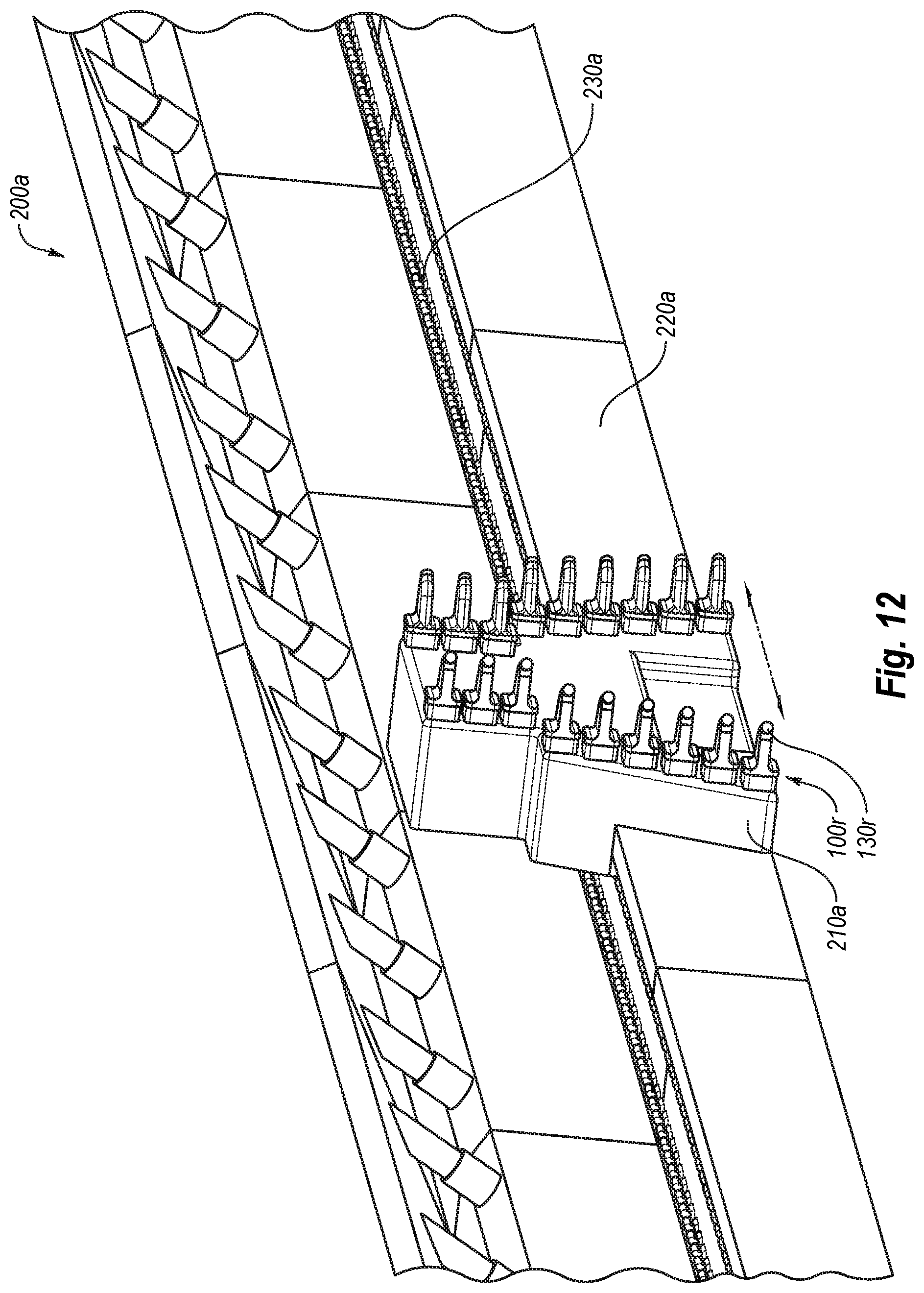
FIG. 12 is an isometric view of a long-wall material-removal system according to at least one embodiment; and
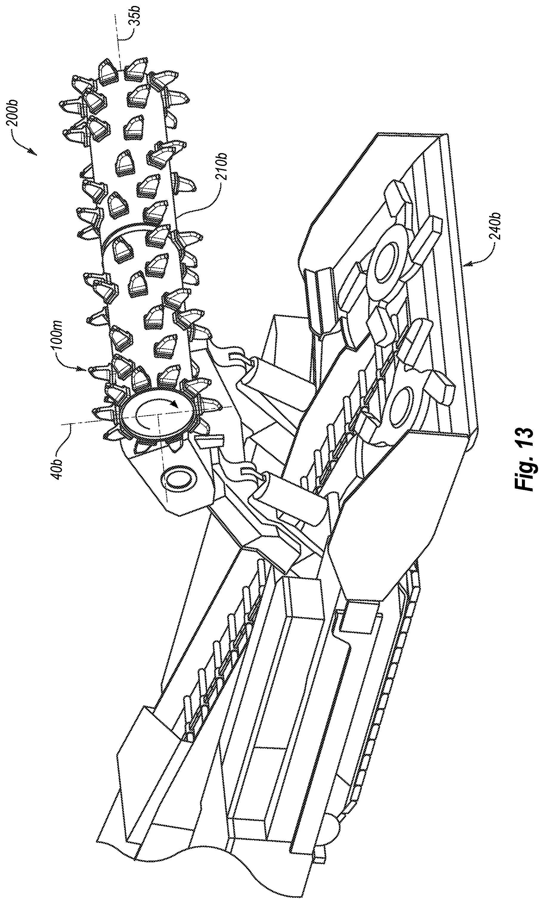
FIG. 13 is an isometric view of a material-removal system that include a cutter head that may rotate about rotation axis and/or move linearly along a vertical axis according to an embodiment.
DETAILED DESCRIPTION
Embodiments described herein relate to material-removal systems and cutting tools that may be used in the material-removal systems. For example, the material-removal systems and, particularly, the cutting tools thereof may engage and fail target material. In some instances, the material-removal systems may be used in mining operations, such as to cut and mine Trona. In other words, For example, the material-removal system may fail and remove or recover the failed target material (e.g., Trona or other material).
Generally, the material-removal systems may include a rotatable cutting head and a plurality of cutting tools attached to the cutting head. Moreover, in an embodiment, at least some of the cutting tools may include superhard material. For example, the superhard material may form or define at least a portion of a working surface and/or at least a portion of a cutting end of the cutting tool. In particular, the working surface and/or the cutting end of the cutting tool may engage the target material (e.g., by plunging and/or cutting, and/or otherwise entering into and/or contacting the target material) and may fail the target material as the cutting head of the material-removal system rotates and/or advances into the target material.
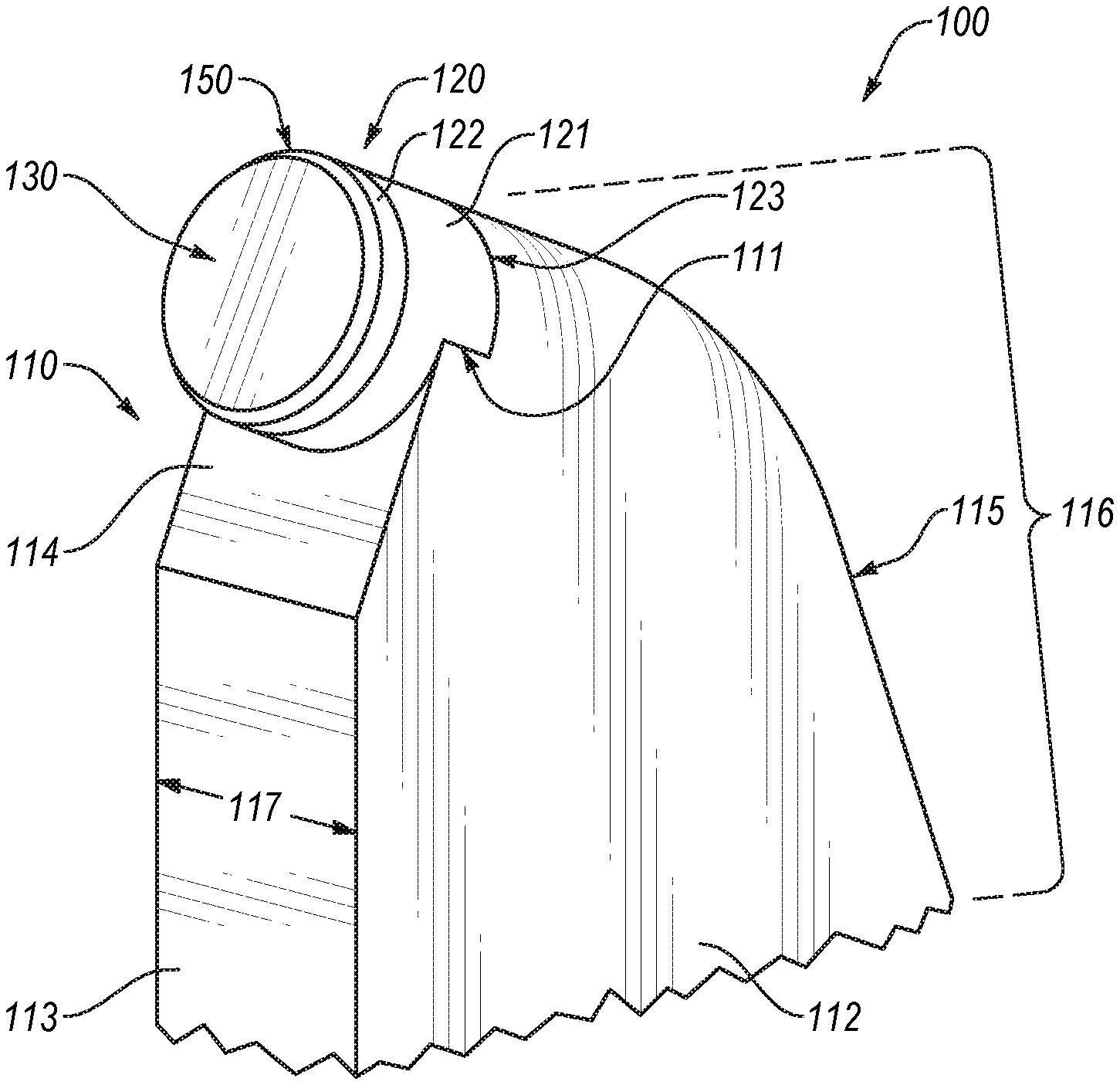
FIGS. 1A-1B illustrate a cutting tool 100 according to an embodiment. For example, the cutting tool 100 may include a tool body 110 (partially shown) and cutting element 120 attached to the tool body 110. Generally, the cutting element 120 may be attached to the tool body 110 in any number of suitable ways and with any number of suitable mechanisms. More specifically, examples of attaching the cutting element 120 to the tool body 110 include brazing, press-fitting, fastening, combinations thereof, or the like.
In some embodiments, the cutting element 120 may include a substrate 121 and a superhard table 122 bonded to the substrate 121. For example, the substrate 121 may include cemented carbide, and the superhard table 122 may include polycrystalline diamond, as described below in more detail. Also, in one or more embodiments, the superhard table 122 may be bonded directly to the tool body 110, which in some instances may include cemented carbide. In any event, the superhard table 122 may include at least a portion of a working surface 130.
As described below in more detail, particular cutting element size, shape, configuration, or combinations thereof may vary from one embodiment to the next. In an embodiment, the cutting element 120 may have a 13 mm diameter and may be 13 mm thick. Alternatively, the cutting element 120 may be thicker or thinner than 13 mm. Likewise, in some instances, the cutting element 120 may have a diameter greater or less than 13 mm. In any event, the cutting element 120 may have a sufficient diameter and/or thickness to withstand operating conditions of the cutting tool 100. For example, a ratio of a width or diameter of the cutting element 120 to a thickness or height of the cutting element 120 may be at least one 1, greater than 1, about 1.2 to about 1.4, or about 1.0 to about 1.5.
In an embodiment, the superhard table 122 may include polycrystalline diamond and the substrate may comprise cobalt-cemented tungsten carbide. Furthermore, in any of the embodiments disclosed herein, the polycrystalline diamond table may be leached to at least partially remove or substantially completely remove a metal-solvent catalyst (e.g., cobalt, iron, nickel, or alloys thereof) that was used to initially sinter precursor diamond particles to form the polycrystalline diamond. In another embodiment, an infiltrant used to re-infiltrate a preformed leached polycrystalline diamond table may be leached or otherwise have a metallic infiltrant removed to a selected depth from a working surface. Moreover, in any of the embodiments disclosed herein, the polycrystalline diamond may be un-leached and include a metal-solvent catalyst (e.g., cobalt, iron, nickel, or alloys thereof) that was used to initially sinter the precursor diamond particles that form the polycrystalline diamond and/or an infiltrant used to re-infiltrate a preformed leached polycrystalline diamond table. Examples of methods for fabricating the superhard tables and superhard materials and/or structures from which the superhard tables and elements may be made are disclosed in U.S. Pat. Nos. 7,866,418; 7,998,573; 8,034,136; and 8,236,074; the disclosure of each of the foregoing patents is incorporated herein, in its entirety, by this reference.
The diamond particles that may be used to fabricate the superhard table in a high-pressure/high-temperature process ("HPHT)" may exhibit a larger size and at least one relatively smaller size. As used herein, the phrases "relatively larger" and "relatively smaller" refer to particle sizes (by any suitable method) that differ by at least a factor of two (e.g., 30 .mu.m and 15 .mu.m). According to various embodiments, the diamond particles may include a portion exhibiting a relatively larger size (e.g., 70 .mu.m, 60 .mu.m, 50 .mu.m, 40 .mu.m, 30 .mu.m, 20 .mu.m, 15 .mu.m, 12 .mu.m, 10 .mu.m, 8 .mu.m) and another portion exhibiting at least one relatively smaller size (e.g., 15 .mu.m, 12 .mu.m, 10 .mu.m, 8 .mu.m, 6 .mu.m, 5 .mu.m, 4 .mu.m, 3 .mu.m, 2 .mu.m, 1 .mu.m, 0.5 .mu.m, less than 0.5 .mu.m, 0.1 .mu.m, less than 0.1 .mu.m). In an embodiment, the diamond particles may include a portion exhibiting a relatively larger size between about 10 .mu.m and about 40 .mu.m and another portion exhibiting a relatively smaller size between about 1 .mu.m and 4 .mu.m. In another embodiment, the diamond particles may include a portion exhibiting the relatively larger size between about 15 .mu.m and about 50 .mu.m and another portion exhibiting the relatively smaller size between about 5 .mu.m and about 15 .mu.m. In another embodiment, the relatively larger size diamond particles may have a ratio to the relatively smaller size diamond particles of at least 1.5. In some embodiments, the diamond particles may comprise three or more different sizes (e.g., one relatively larger size and two or more relatively smaller sizes), without limitation. The resulting polycrystalline diamond formed from HPHT sintering the aforementioned diamond particles may also exhibit the same or similar diamond grain size distributions and/or sizes as the aforementioned diamond particle distributions and particle sizes. Additionally, in any of the embodiments disclosed herein, the superhard cutting elements may be free-standing (e.g., substrateless) and/or formed from a polycrystalline diamond body that is at least partially or fully leached to remove a metal-solvent catalyst initially used to sinter the polycrystalline diamond body.
As noted above, the superhard table 122 may be bonded to the substrate 121. For example, the superhard table 122 comprising polycrystalline diamond may be at least partially leached and bonded to the substrate 121 with an infiltrant exhibiting a selected viscosity, as described in U.S. patent application Ser. No. 13/275,372, entitled "Polycrystalline Diamond Compacts, Related Products, And Methods Of Manufacture," the entire disclosure of which is incorporated herein by this reference. In an embodiment, an at least partially leached polycrystalline diamond table may be fabricated by subjecting a plurality of diamond particles (e.g., diamond particles having an average particle size between 0.5 .mu.m to about 150 .mu.m) to an HPHT sintering process in the presence of a catalyst, such as cobalt, nickel, iron, or an alloy of any of the preceding metals to facilitate intergrowth between the diamond particles and form a polycrystalline diamond table comprising bonded diamond grains defining interstitial regions having the catalyst disposed within at least a portion of the interstitial regions. The as-sintered polycrystalline diamond table may be leached by immersion in an acid or subjected to another suitable process to remove at least a portion of the catalyst from the interstitial regions of the polycrystalline diamond table, as described above. The at least partially leached polycrystalline diamond table includes a plurality of interstitial regions that were previously occupied by a catalyst and form a network of at least partially interconnected pores. In an embodiment, the sintered diamond grains of the at least partially leached polycrystalline diamond table may exhibit an average grain size of about 20 .mu.m or less. Subsequent to leaching the polycrystalline diamond table, the at least partially leached polycrystalline diamond table may be bonded to a substrate in an HPHT process via an infiltrant with a selected viscosity. For example, an infiltrant may be selected that exhibits a viscosity that is less than a viscosity typically exhibited by a cobalt cementing constituent of typical cobalt-cemented tungsten carbide substrates (e.g., 8% cobalt-cemented tungsten carbide to 13% cobalt-cemented tungsten carbide).
Additionally or alternatively, the superhard table 122 may be a polycrystalline diamond table that has a thermally-stable region, having at least one low-carbon-solubility material disposed interstitially between bonded diamond grains thereof, as further described in U.S. patent application Ser. No. 13/027,954, entitled "Polycrystalline Diamond Compact Including A Polycrystalline Diamond Table With A Thermally-Stable Region Having At Least One Low-Carbon-Solubility Material And Applications Therefor," the entire disclosure of which is incorporated herein by this reference. The low-carbon-solubility material may exhibit a melting temperature of about 1300.degree. C. or less and a bulk modulus at 20.degree. C. of less than about 150 GPa. The low-carbon-solubility, in combination with the high diamond-to-diamond bond density of the diamond grains, may enable the low-carbon-solubility material to be extruded between the diamond grains and out of the polycrystalline diamond table before causing the polycrystalline diamond table to fail during operations due to interstitial-stress-related fracture.
In some embodiments, the polycrystalline diamond, which may form the superhard table, may include bonded-together diamond grains having aluminum carbide disposed interstitially between the bonded-together diamond grains, as further described in U.S. patent application Ser. No. 13/100,388, entitled "Polycrystalline Diamond Compact Including A Polycrystalline Diamond Table Containing Aluminum Carbide Therein And Applications Therefor," the entire disclosure of which is incorporated herein by this reference.
In some embodiments, the tool body 110 may include a recess 111 that may accept at least a portion of the cutting element 120 (e.g., at least a portion of the substrate 121 of the cutting element 120 may be positioned within the recess 111). Moreover, in some embodiments, the recess 111 may locate and/or orient the cutting element 120 relative to one or more features of the tool body 110 (e.g., relative to one or more surface of the tool body 110, such as a side surface 112, front surface 113, front slanted surface 114, etc.). As described below in more detail, For example, the recess 111 may orient the cutting element 120 in a manner that the working surface 130 forms one or more rake angles (e.g., a back rake angle and/or a side rake angle).
In some embodiments, the recess 111 in the tool body 110 may orient the cutting element 120 in a manner that forms the back and/or side rake of working surface 130. For example, the working surface 130 may be formed by the superhard table 122 and/or may be generally parallel to a back surface 123 of the substrate 121. Hence, to form the back rake and/or side rake angles, the recess 111 may orient the substrate 121 in a manner that orients the working surface 130 at a desired or suitable back and/or side rake angles.
Additionally or alternatively, in an embodiment, the working surface 130 may lie in a plane that is non-parallel relative to the back surface 123 of the substrate 121. For example, the superhard table 122 may be cut (e.g., wire EDM cut) or ground at an angle relative to the back surface 123 of the substrate 121 to produce a side and/or back rake angles. However, the side and/or back rake angles produced by orienting the working surface 130 at a non-parallel angle relative to the back surface 123 of the substrate 121 may be smaller or greater than a desired or suitable back and/or side rake angle. Hence, in some embodiments, the recess 111 may provide further orientation and/or location of the working surface 130, which is non-parallel to the back surface 123 of the substrate 121, in a manner that the recess 111 orients the working surface 130 to a desired and/or suitable back and/or side rake angles.
In an embodiment, a portion of the substrate 121 may be exposed outside of the recess 111 and/or tool body 110. For example, a top portion of the peripheral surface of the substrate 121 may be exposed and located outside of the tool body 110. Moreover, in an embodiment, at least part of the top portion of the peripheral surface of the substrate 121 may be, generally, tangent to a back surface 115 of the tool body 110 and/or may form an extension thereof. In other words, the back surface 115 of the tool body 110 may smoothly transition to the exposed portion of the peripheral surface of the substrate 121.
In some embodiments, the exposed portion of the substrate 121 may engage cuttings of the target material. Hence, for example, the exposed portion of the substrate 121 may erode or wear during operation of the cutting tool 100. Also, in some embodiments, the exposed portion of the substrate 121 may protect or shield at least a portion and/or one or more surfaces of the tool body 110 from wear during operation of the cutting tool 100. For example, the exposed portion of the substrate 121 may shield one or more portions of the tool body 110 from engagement with target material, which may increase useful life of the tool body 110 and the cutting tool 100.
In an embodiment, the working surface 130 may be substantially planar and/or may have a substantially circular shape (i.e., may be defined by a circular perimeter or boundary). Alternatively, the working surface may be non-planar (e.g., conical, bullet-shaped, etc.). Likewise, the general shape of the cutter element may vary from one embodiment to the next and may be generally cylindrical or non-cylindrical.
Also, the cutting tool 100 may include a cutting end 150. The cutting end 150 may define at least a portion of a perimeter or boundary of the working surface 130. Generally, in some embodiments, the cutting end 150 may be formed or defined at an edge region, which may be formed by and between two or more surfaces of the cutting element 120. For example, the cutting end 150 may be formed at an interface between the working surface 130 and a peripheral surface of the cutting element 120. It should be appreciated, however, that the cutting end may be formed at or include a surface, such as a chamfer, which may extend between two or more surfaces of the cutting element 120, as described below.
The working surface 130 and/or cutting end 150 may engage the target material. For example, the working surface 130 may penetrate into the target material, and movement of the working surface 130 and/or cutting end 150 within and/or against the target material may cut, grind, combinations thereof, or otherwise fail the target material. In some embodiments, the working surface 130 may be oriented at an angle relative to a longitudinal axis 10 (FIG. 1B), in a manner that forms a back rake angle .theta. with the longitudinal axis 10. The longitudinal axis 10 may be substantially perpendicular to a tangent line 20, where tangent line 20 is tangent (at an uppermost point of the cutting end 150) to a circular path along which the cutting tool 100 moves during rotation thereof.
For example, the back rake angle .theta. may be a negative back rake angle in one or more of the following ranges: about 1 degree to about 5 degrees; about 4 degrees to about 10 degrees; about 8 degrees to 20 degrees (e.g., greater than 17 degrees); and about 15 degrees to 30 degrees. In some embodiments, the back rake angle .theta. may be less than 1 degree or greater than 30 degrees. Moreover, as shown in FIGS. 1A-1B, according to an embodiment, the working surface 130 may have a negative back rake angle. Alternatively, however, as described below in more detail, the working surface may have a positive back rake angle (e.g., a back rake angle formed by the working surface 130 rotated clockwise from the longitudinal axis 10 is negative, while the back rake angle formed by the working surface 130 rotated counterclockwise from the longitudinal axis 10 is positive).
As described above, in an embodiment, the tool body 110 may include the slanted surface 114. For example, the slanted surface 114 may be approximately parallel to the working surface 130. Moreover, the slanted surface 114 may be offset from the working surface 130. In any event, the working surface 130 and/or the 114 may be oriented in a manner that facilitates movement or flow of the failed target material away from the cutting tool 100. For example, the failed target material may move or slide along the working surface 130 and away from the cutting end 150.
The tool body 110 may have any suitable shape and/or configuration, which may vary from one embodiment to the next. Generally, the tool body 110 may be configured to be attached to a cutting head of the material-removal system. In one or more embodiments, the tool body 110 may have an elongated portion 116, which may extend from an attachment portion (not shown) that may secure the cutting tool 100 to the cutting head of the material-removal system.
In some embodiments, the elongated portion 116 may have a width 117 that may be similar to or the same as the width or diameter of the cutting element 120. For example, the peripheral surface of the substrate 121 may not protrude past one or more of the side surfaces of the tool body 110 (e.g., side surface 112). Thus, according to an embodiment, matching the width of the cutting element 120 and tool body 110 may reduce drag experienced by the tool body 110 during movement in or through the target material.
While, as described above, the working surface 130 may form a negative back rake angle .theta., in another embodiment, the working surface 130 may form a positive back rake angle. More specifically, FIG. 2 illustrates a cutting tool 100a according to an embodiment, which includes working surface 130a that has a positive back rake angle (p. Except as otherwise described herein, the cutting tool 100a and its materials, elements, or components may be similar to or the same as the cutting tool 100 (FIGS. 1A-1B) and its corresponding materials, elements, and components. For example, the cutting tool 100a may include a cutting element 120a that may be attached to a tool body 110a; the cutting element 120a may be similar to or the same as the cutting element 120 (FIGS. 1A-1B).
Particularly, in some embodiments, the back rake angle .phi. may be formed between the working surface 130a and a longitudinal axis 10. The magnitude of the back rake angle .phi. may be in one or more ranges described above in connection with back rake angle .theta. (FIG. 1B). In any event, the working surface 130a may be angled or oriented in a manner that facilitates flow or movement of failed target material away from the working surface 130a and/or from a cutting end 150a.
In some instances, the failed target material may move along the working surface 130a and toward the tool body 110a. Furthermore, in an embodiment, the tool body 110 may be configured to channel the failed target material away from the cutting tool 100 (e.g., away from the working surface 130a and/or cutting end 150a). For example, the tool body 110a may include one or more slanted surfaces, such as the slanted surface 114a, which may guide or channel failed target material away from the cutting tool 100. In other words, the failed target material may move across the working surface 130a and onto a portion of the tool body 110 (e.g., the slanted surface 114a), which may further guide or channel the failed target material away from the cutting tool 100a.
In one or more embodiments, the slanted surface 114a may be oriented at a non-parallel angle relative to the longitudinal axis 10 (i.e., the slanted surface 114a may be oriented at an obtuse or an acute angle relative to the longitudinal axis 10). Additionally or alternatively, the slanted surface 114a may have a non-parallel orientation relative to the working surface 130a. For example, the slanted surface 114a of the tool body 110a may be oriented at a non-parallel angle relative to the working surface 130a.
As described above, in some embodiments, the cutting element 120a may include a superhard table 122a bonded to a substrate 121a. Moreover, a portion of the substrate 121a may be exposed outside of the tool body 110a. For example, an upper portion of the peripheral surface of the substrate 121a may be exposed outside of the tool body 110a. In an embodiment, the exposed portion of the peripheral surface of the substrate 121a may extend from a back surface 115a of the tool body 110a. Furthermore, in some instances, the back surface 115a of the tool body 110a may smoothly transition to the exposed portion of the peripheral of the substrate 121a.
Alternatively, in an embodiment, the back surface 115a of the tool body 110a may have a non-smooth transition (e.g., angled, stepped, uneven, etc.) between a back surface of the tool body and the exposed portion of the peripheral surface of the substrate. FIG. 3 illustrates a cutting tool 100b, which includes such a transition between back surface 115b of the tool body 110b and upper portion 124b of the peripheral surface 121b, according to an embodiment. Except as otherwise described herein, the cutting tool 100b and its materials, elements, or components may be similar to or the same as any of the cutting tools 100, 100a (FIGS. 1A-2) and their corresponding materials, elements, and components. For example, the cutting tool 100b may include a tool body 110b that may be similar to or the same as the tool body 110 (FIGS. 1A-1B).
In an embodiment, the cutting tool 100b may include a cutting element 120b secured to the tool body 110b. The cutting element 120b may include a superhard table 122b bonded to a substrate 121b. Moreover, in some examples, the cutting element 120b may be attached in a recess 111b of the tool body 110b (e.g., the substrate 121b of the cutting element 120 may be at least partially positioned within the recess 111b). As described above, at least a portion of the substrate 121b may be exposed out of the tool body 110b. In particular, for example, an upper portion 124b of the peripheral surface of the substrate 121b may be exposed outside of the tool body 110b.
In an embodiment, the upper portion 124b of the peripheral surface of substrate 121b may be tapered in a manner that forms a non-parallel angle .alpha. (e.g., acute or obtuse angle) with a working surface 130b of the cutting tool 100b (e.g., with the working surface 130b formed by the superhard table 122b). In an embodiment, at least a portion of the peripheral surface of the substrate 121b may have a tapered shape (e.g., a partially or completely conical shape). Also, For example, working surface 130b may form the angle .alpha. with a reference line 15, which may be substantially parallel to the cross-section of the peripheral surface of the substrate 121b at an uppermost location of the upper portion 124b thereof.
Tapering the upper portion 124b of the peripheral surface of the substrate 121b may facilitate clearance between the substrate 121b and the target material. Likewise, the taper of the upper portion 124b may provide clearance for failed material that may be between a new surface (formed after failing and/or removing target material) and the substrate 121b. Thus, in some embodiments, tapered upper portion 124b of the substrate 121b may increase useful life of the cutting tool 100b.
Generally, the angle .alpha. may vary from one embodiment to the next. In some embodiments, the angle .alpha. may be in one or more of the following ranges: about 15 degrees to 30 degrees; about 20 degrees to 45 degrees; about 40 degrees to 70 degrees; and about 50 degrees to 89 degrees. It should be appreciated that, in some embodiments, the angle .alpha. may be less than 15 degrees or greater than 89 degrees.
In some instances, the upper portion 124b of the substrate 121b may resemble and/or may define a chamfer. Moreover, the taper of the upper portion 124b of the substrate 121b may extend from a back surface 123b of the substrate 121b to an interface 125b between the substrate 121b and the superhard table 122b. Alternatively, the taper of the upper portion 124b may extend only part of the distance between the back surface 123b and the interface 125b.
For example, the taper may start and extend from the back surface 123b and terminate at a distance less than the distance between the back surface 123b and the interface 125b (e.g., the upper portion may include a step between the tapered portion and a non-tapered portion, which may extend from the tapered portion to the interface). Alternatively or additionally, a taper of the upper portion may extend from the interface and may terminate at a distance that is less than the distance between the interface 123b and the back surface 125b.
Furthermore, as described above, the cutting tool 100b may include a step or other discontinuity between a back surface 115b of the tool body 110b and the peripheral surface of the substrate 121b (e.g., the upper portion 124b of the peripheral surface). More generally, the portion of the peripheral surface of the substrate 121b extending from the back surface 115b may be incongruous with the adjacent portion of the back surface 115b. Accordingly, in some embodiments, the failed material that flows or moves along the upper portion 124b of the peripheral surface of the substrate 121b may change direction of movement as the material encounters the back surface 115b and may further move away from the substrate 121b.
In one or more embodiments, at least a portion of the peripheral surface of the superhard table 122b also may include a taper. For example, the taper of the peripheral surface of the superhard table 122b may generally form a continuation or extension of the taper formed on the upper portion 124b of the peripheral surface of the substrate 121 (i.e., the taper may form an angle with the working surface 130b). Hence, in some instances, the taper angle of the peripheral surface of the superhard table 122b may be in one or more ranges described above in connection with angle .alpha.. Also, in an embodiment, the taper of the peripheral surface of the superhard table 122b may be different from the taper of the peripheral surface of the substrate 121b.
In other embodiments, the substrate and/or superhard table may be tapered in a variety of other manners than those illustrated. For example, U.S. Pat. No. 5,881,830, which is incorporated herein in its entirety by this reference, discloses a variety of tapering geometries that may be employed in other embodiments.
As mentioned above, the working surface may be oriented in a manner that forms a side rake angle during operation of the cutting tool. FIG. 4 illustrates a cutting tool 100c that includes a working surface 130c, which forms a side rake angle .lamda., according to an embodiment. Except as otherwise described herein, the cutting tool 100c and its materials, elements, or components may be similar to or the same as any of the cutting tools 100, 100a, or 100b (FIGS. 1A-3) and their corresponding materials, elements, and components. For example, the cutting tool 100c may include a tool body 110c that may be similar to or the same as the tool body 110 (FIGS. 1A-1B). In some embodiments, the cutting tool 100c may include a cutting element 120c, which may have a superhard table 122c bonded to a substrate 121c. Moreover, the superhard table 122c includes at least a portion of the working surface 130c. The cutting element 120c may be attached to the tool body 110c.
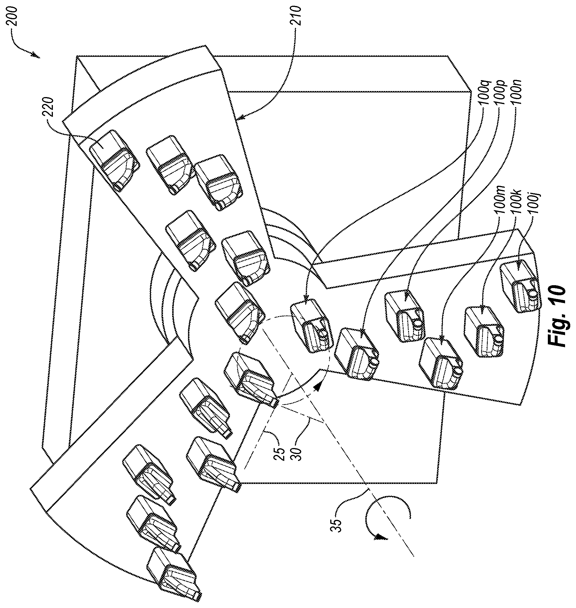
In an embodiment, the side rake angle .lamda. may be formed between the working surface 130c and a reference line 25, which may be perpendicular to a path or direction of movement of the cutting tool 100c during operation thereof. For example, the reference line 25 may be an imaginary line extending between a rotation axis of the cutting head to which the cutting tool 100c is attached and a nearest point of working surface 130c wherein the imaginary line is substantially perpendicular to a rotation axis of the cutting head to which the cutting tool 100c is attached (e.g., as shown in FIG. 10, the reference line 25 may be perpendicular to a tangent line 30, which may be tangent to a radial path of the cutting tool rotating together with the cutter head). Generally, the side rake angle .lamda. may vary from one embodiment to the next. For example, the side rake angle .lamda. may be in one or more ranges described above in connection with back rake angle .theta. (FIG. 1A). Moreover, it should be appreciated that in addition to the side rake angle .lamda., the working surface 130c may be oriented at a back rake angle.
As noted above, the working surface 130c may be oriented relative to the tool body 110c at a desired or suitable side rake angle .lamda. and/or back rake angle by orienting the working surface 130c at such angle relative to a back surface 123c of the substrate 121c or by orienting the pocket in which the cutting element is disposed. In an embodiment, a portion of the superhard table 122c may be thinner than another portion of the superhard table 122c. In particular, in some embodiments, the superhard table 122c may be a tapered (e.g., one side of the superhard table 122c may be thinner than another side of the superhard table 122c) in a manner that forms a suitable or desired angle between the working surface 130c and the back surface 123c. Moreover, the angle formed between the working surface 130c and the back surface 123c may be the same as the side rake angle .lamda. and/or the back rake angle .theta. (described above). Thus, in some embodiments, the working surface 130c and the back surface 123c may exhibit selected angles with respect to different cross-sectional views taken through cutting element 120c.
Alternatively, the back rake angle and/or the side rake angle may be formed by orienting the cutting element relative to the tool body. FIG. 5 illustrates a cutting tool 100d according to an embodiment, which includes such configuration. Except as otherwise described herein, the cutting tool 100d and its materials, elements, or components may be similar to or the same as any of the cutting tools 100, 100a, 100b, or 100c (FIGS. 1A-4) and their corresponding materials, elements, and components. For example, the cutting tool 100d may include a tool body 110d that may be similar to or the same as the tool body 110 (FIGS. 1A-1B).
In some embodiments, the cutting tool 100d may include a working surface 130d that is substantially parallel to a back surface 123d of a cutting element 120d. For example, the cutting element 120d may be attached to the tool body 110d of the cutting tool 100d and may provide the working surface 130d at a desired or suitable side and/or back rake angle. Furthermore, the cutting element 120d may include a substrate 121d and a superhard table 122d bonded to the substrate 121d, and the substrate 121d may include the back surface 123d.
In an embodiment, the back surface 123d may abut or contact a surface 118d of the tool body 110d. For example, the cutting element 120d may be secured in a recess (as described above), and the back surface 123d of the substrate 121d may be positioned and/or oriented by the surface 118d of the tool body 110d, which define a portion of the recess of the tool body 110d. Moreover, in some embodiments, the back surface 123d may be attached to the surface 118d of the tool body 110d (e.g., by brazing, etc.). In any event, in some embodiments, the surface 118d of the tool body 110d may position and/or orient the back surface 123d. Thus, according to an embodiment, the surface 118d of the tool body 110d may orient the working surface 130d at a suitable side rake angle and/or at a back rake angle. More specifically, in some embodiments, the superhard table 122d may have an approximately uniform thickness and/or the working surface 130d may be substantially parallel to the back surface 123d, and the surface 118d may orient the working surface 130d at a suitable side and/or back rake angle(s).
Generally, in some embodiments, the cutting element may include a cutting end that may be formed by and between the peripheral surface of the superhard table and the working surface. In other words, the cutting end of the cutting element may be a substantially sharp corner between the working surface and the peripheral surface of the superhard table, which may facilitate penetration of the cutting element into the target material. In additional or alternative embodiments, the cutting element may include one or more chamfers that may at least partially surround the working surface, which may improve impact resistance or durability of the superhard table or cutting edge. FIG. 6 illustrates a cutting element 120e that includes a chamfer 126e that surrounds a working surface 130e, according to an embodiment.
Except as otherwise described herein, the cutting element 120e and its materials, elements, or components may be similar to or the same as any of the cutting elements 120, 120a, 120b, 120c, or 120d (FIGS. 1A-5) and their corresponding materials, elements, and components. For example, cutting element 120e may include a substrate 121e and a superhard table 122e that may be bonded to the substrate 121e; the substrate 121e and/or the superhard table 122e may be similar to the substrate 121 and superhard table 122 of the cutting element 120 (FIGS. 1A-1B). The cutting element 120e may include a cutting end 150e that may be defined or formed by: the chamfer 126e; an edge between the working surface 130e and the chamfer 126e; an edge between the chamfer 126e and superhard table 122e; or at least a portion of one or more of the foregoing. Accordingly, in some instances, the cutting end 150e may include at least a portion of an edge or corner and/or may include at least a portion of a surface (e.g., the surface formed by the chamfer 126e).
Also, under some operating conditions, the chamfer 126e may improve impact resistance or durability of the superhard table 122e and/or of the cutting end 150e (as compared with the cutting end formed at a sharp corner between the peripheral surface of the superhard table and the working surface). Furthermore, it should be appreciated that the size and/or orientation of the chamfer 126e may vary from one embodiment to the next. In some embodiments, the sharp edge between the working surface 130e and the peripheral surface of the superhard table 122e may be broken to form a relatively small chamfer 126e or radius (e.g., chamfer or radius of 0.001 inch, 0.005 inch, etc.). The chamfer 126e, however, may be larger if desired. For example, the chamfer 126e may be 0.05 inches, 0.10 inches, 0.15 inches, 0.020 inches, 0.030 inches, etc. Moreover, in some embodiments, the chamfer 126e may be larger than 0.05 inches.
In an embodiment, the working surface 130e may have an approximately circular shape. Consequently, the chamfer 126e also may have an approximately conical geometry (i.e., the chamfer 126e may encircle the working surface 130e and may define the shape and size of the working surface 130e). It should be appreciated, however, that a particular shape and/or size of the working surface 130e may vary from one embodiment to the next, as described below in further detail.
In some embodiments, working surface 130e may be substantially planar. Further, in some instances, the superhard table 122e may be bonded to the substrate 121e over a substantially planar interface 125e. In an embodiment, however, the superhard table may be bonded to the substrate over a nonplanar interface. FIG. 7 illustrates a cutting element 120f according to one or more alternative or additional embodiments. More specifically, in some examples, the cutting element 120f may include a superhard table 122f bonded to a substrate 121f over a nonplanar interface 125f. Except as otherwise described herein, the cutting element 120f and its materials, elements, or components may be similar to or the same as any of the cutting elements 120, 120a, 120b, 120c, 120d, 120e (FIGS. 1A-6) and their corresponding materials, elements, and components.
According to an embodiment, the interface 125f may include multiple corresponding and/or complementary grooves formed on the substrate 121f and superhard table 122f. In alternative or additional embodiments, a nonplanar interface between the superhard table the substrate may include any number of features, which may be complementary with one another, such that a feature protruding from the substrate may enter a recess in the superhard table and vice versa. In any event, in an embodiment, a nonplanar interface between the substrate a superhard table may improve impact resistance or durability of the cutting element (as compared with a cutting element that has a planar interface between the superhard table and the substrate).
As described above, in some embodiments, a cutting element may include a working surface that is oriented at a nonparallel angle relative to a back surface of the cutting element. FIG. 8 illustrates a cutting element 120g that includes a working surface 130g that is oriented at a nonparallel angle relative to the back surface 123g, according to an embodiment. Except as otherwise described herein, the cutting element 120g and its materials, elements, or components may be similar to or the same as any of the cutting elements 120, 120a, 120b, 120c, 120d, 120e, 120f (FIGS. 1A-7) and their corresponding materials, elements, and components. For example, the cutting element 120g may include a superhard table 122g bonded to a substrate 121g, which may be similar to substrate 121 and superhard table 122 (FIGS. 1A-1B).
According to an embodiment, the cutting element 120g includes the working surface 130g that forms an angle .beta. with the back surface 123g. More specifically, the angle .beta. may form, at least to some extent, the side rake and/or back rake angle, as described above. Accordingly, in some embodiment, the cutting element 120g may be formed in a manner that predefines the side and/or back rake angles, depending on the orientation of the cutting element 120g (e.g., in addition to or in lieu of such angles being defined by the tool body).
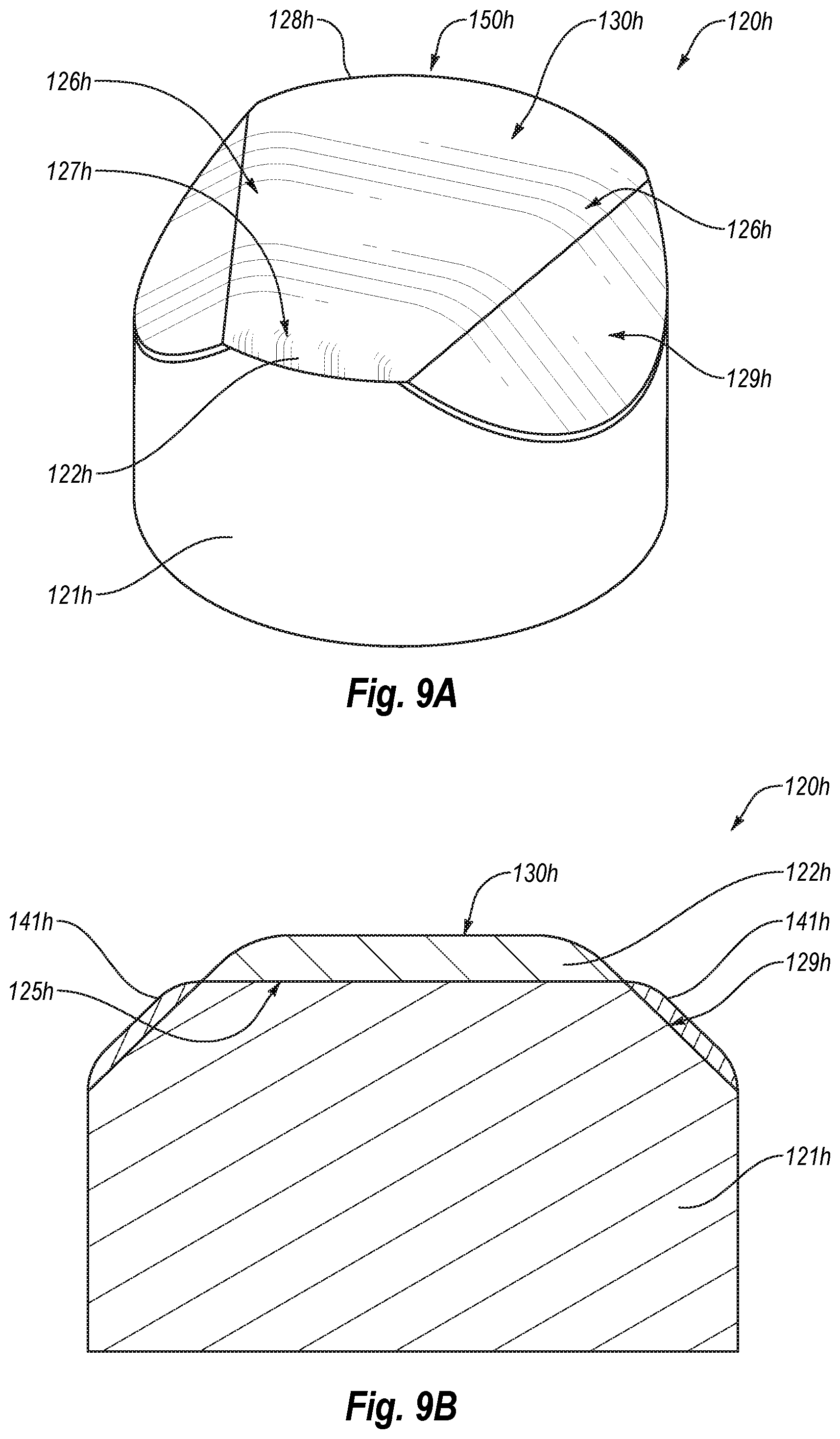
Also, in some embodiments, the cutting element may have non-circular working surface. FIGS. 9A-9B illustrate a cutting element 120h that includes a working surface 130h, which may have an approximately or generally trapezoidal shape, according to an embodiment. Except as otherwise described herein, the cutting element 120h and its materials, elements, or components may be similar to or the same as any of the cutting elements 120, 120a, 120b, 120c, 120d, 120e, 120g, or 120h (FIGS. 1A-8) and their corresponding materials, elements, and components. For example, the cutting element 120h may include a superhard table 122h bonded to a substrate 121h, which may be similar to the respective substrate 121 and superhard table 122 of the cutting element 100 (FIGS. 1A-1B).
In some embodiments, the working surface 130h may be bounded by one or more fillets or radii 126h, 127h, 128h, which may extend from the working surface 130h to a periphery of the superhard table 122h (e.g., to a peripheral surface of the superhard table 122h). As such, the radii 126h, 127h, 128h may define an approximately trapezoidal shape of the working surface 130h. For example, the radii 126h may define two opposing, sides of the trapezoidal shape of the working surface 130h. Additionally, the radii 126h and 128 may define two opposing sides of the trapezoidal shape of the working surface 130h.
Also, the cutting element 120h may include a cutting end 150h (e.g., the cutting end 150h may be formed by the radius 128h). It should be appreciated that the cutting element 120h may have a sharp corner or edge instead of the radius 128h. Accordingly, embodiments may include the cutting end 150h that is formed by a sharp corner, a chamfer, a radius, or combinations thereof. Moreover, in lieu of any of the radii 126h, 127h, 128h the cutting element 120h may include a shape edge.
The cutting element 120h may include one or more slanted surfaces, such as slanted surfaces 129h. For example, the slanted surfaces 129h may pass through an otherwise cylindrical shape of the cutting element 120h. Moreover, the slanted surfaces 129h may be included on a portion of the substrate 121h and/or of the superhard table 122h.
In the illustrated embodiment, one or more of the slanted surfaces 129h may include a protective coating 141h that may protect the slanted surfaces 129h from wear and/or damage during operation of the cutting tool. In other words, as the cutting element 120h engages the target material, the slanted surfaces 129h may contact the target material as well as the failed target material, which may wear or damage the slanted surfaces 129h in a manner that reduces the useful life of the cutting element 120h. Accordingly, protecting the slanted surfaces 129h from wear and/or damage may increase the useful life of the cutting element 120h. For example, the protective coating 141h may comprise titanium nitride (TiN), titanium aluminum nitride (TiAlN), chemical vapor deposited diamond, binderless tungsten carbide, similar coatings, or combinations thereof. In an embodiment, the binderless tungsten carbide layer may be formed by chemical vapor deposition ("CVD") or variants thereof (e.g., plasma-enhanced CVD, etc., without limitation). An example of a commercially available CVD tungsten carbide layer (currently marketed under the trademark HARDIDE.RTM.) is currently available from Hardide Layers Inc. of Houston, Tex. In other embodiments, a tungsten carbide layer may be formed by physical vapor deposition ("PVD"), variants of PVD, high-velocity oxygen fuel ("HVOF") thermal spray processes, or any other suitable process, without limitation. However, in other embodiments, the one or more protective coating 141h may be omitted and the substrate 121h may be exposed.
In an embodiment, the cutting element 120h may include a substantially planar interface 125h between the superhard table 122h and the substrate 121h. For example, the interface 125h may extend between the opposing slanted surfaces 129h (FIG. 9B). Hence, the superhard table 122h may extend between the uppermost edges of the slanted surfaces 129h.
It should be appreciated that any of the cutting tools described herein may include any of the cutting elements described herein. Moreover, any of the cutting elements may include one or more features or elements described herein in connection with any other cutting element. Also, as described above, any of the cutting tools described herein may be attached to a cutting head of a material-removal system.
FIG. 10 illustrates a material-removal system 200 according to an embodiment. More specifically, the material-removal system 200 may include a cutting head 210 that is rotatable about a rotation axis 35. Furthermore, the cutting head 210 includes a plurality cutting tools secured thereto. Specific arrangement of the cutting tools on the cutting head 210 may vary from one embodiment to the next. For example, the cutting head 210 may include cutting tools 100j-q secured thereto.
For example, as shown in FIG. 11, the cutting tool 100j may be mounted on and/or attached to a holder 220. Generally, except as otherwise described herein, the cutting tool 100j and its materials, elements, or components may be similar to or the same as any of the cutting tools 100, 100a, 100b, 100c, 100d (FIGS. 1A-5) and their corresponding materials, elements, and components. In an embodiment, the cutting tool 110j may include a tool body 110j that has an elongated portion 116j projecting outward from a base portion 117j. For example, the tool body 110j and/or the elongated portion 116j may be similar to or the same as the tool bodies and/or elongated portions or elongated regions described in U.S. patent application Ser. No. 14/266,437, entitled "Cutting Tool Assemblies Including Superhard Working Surfaces, Material-Removing Machines Including Cutting Tool Assemblies, And Methods Of Use," filed on Apr. 30, 2014. In some embodiments, the tool body 110j may be similar to or the same as pick bodies described in U.S. patent application Ser. No. 14/275,574, entitled "Shear Cutter Pick Milling System," filed on May 12, 2014. Furthermore, in at least one embodiment, the tool body 110j may be similar to or the same as pick bodies described in U.S. patent application Ser. No. 14/273,360, entitled "Road-Removal System Employing Polycrystalline Diamond Compacts," filed on May 8, 2014. Each of the foregoing U.S. Patent Applications is incorporated herein in its entirety by this reference.
Referring back to FIG. 10, in some examples, the cutting head 210 may include multiple holders 220 that may secure the cutting tools 100j-q. The holders 220 may be attached to or integrated with the cutting head 210. In any event, in an embodiment, the cutting tools 100j-q may be attached to the cutting head 210 and may rotate together therewith about the rotation axis 35. Additionally, as described above, as the cutting head 210 rotates and advances toward and/or into the target material, the cutting tools 100j-q may also advance toward and/or into the target material, thereby cutting into and/or failing the target material (as the cutting head 210 rotates).
In an embodiment, the cutting tools 100j-q may include corresponding working faces that may generally face in the direction of rotation of the cutting head 210 and cutting tools 100j-q (as indicated by the arrow). Hence, the working surfaces and/or cutting ends of the cutting tools 100j-q may engage and fail the target material as the cutting head 210 rotates about the rotation axis 35. Moreover, as described above, the working surface may have back and/or side rake angles.
For example, the side rake angles of one, some, or all of the cutting tools 100j-q may open toward the rotation axis 35 or away therefrom. In other words, in some embodiments, at least some of the working faces may have a side rake angle that faces toward the rotation axis 35, such that the portion of the working face that is farthest from an imaginary radius line is closer to the rotation axis 35 than the portion of the working surface that is closest to an imaginary radius line. Conversely, in an embodiment, at least some of the working faces may have a side rake angle that faces away from the rotation axis 35, such that the portion of the working face that is closest to an imaginary radius line is closer to the rotation axis 35 than the portion of the working surface that is farthest from the imaginary radius line
In some embodiments, two or more of the cutting tools 100j-k may have different positions or locations one from another relative to the rotation axis 35. In other words, two or more of the cutting tools 100j-k may have different radial spacing one from another. For example, the cutting tools 100j may be spaced farther away from the rotation axis 35 than cutting tools 100k-q.
In an embodiment, the cutting tools 100j-q may be the same or substantially the same (e.g., the cutting tools 100j-q may include the same or similar cutting elements). Alternatively, one or more of the cutting tools 100j-q may be different from other cutting tools 100j-q. In one or more embodiments, the cutting tools 100j-k may vary depending on their respective radial position relative to the rotation axis 35.
For example, the cutting tools located closer to the rotation axis 35 may have a larger side and/or back rake angle than the cutting tools located farther from the rotation axis 35. For example, the side and/or back rake angles of the working surfaces may increase as the distance from the rotation axis of the cutting tool decreases (i.e., as the radial path of the cutting tool in operation decreases). More specifically, in an embodiment, the cutting tools 100q may include working surface that have larger side rake angles than the working surfaces of the cutting tools 100j, which may be located at a position that is farther away from the rotation axis 35 than the cutting tools 100q.
In one or more embodiments, impact resistance of the cutting elements of the cutting tools 100j-q may vary with distance from the rotation axis 35. More specifically, in an embodiment, the cutting tools located closer to the rotation axis 35 may have cutting elements that have greater impact resistance than the cutting tools that are located farther away from the rotation axis 35. For example, the cutting tools 100q may include cutting elements that have a higher impact resistance that cutting elements of the cutting tools 100j.
As described above, the cutting elements that include a chamfer that forms a cutting end, and which at least partially surrounds the working surface may have an increased impact resistance (as compared with cutting elements that have a sharp edge in lieu of a chamfer). Also, cutting elements that have a nonplanar interface between the substrate and superhard table may have increased impact resistance (as compared with cutting elements that have a planar interface). Accordingly, in some embodiments, some of the cutting tools located closer to the rotation axis 35 may include cutting elements that include a chamfer and/or a nonplanar interface (superhard table to substrate interface), while some of the cutting tools located farther from the rotation axis 35 may include cutting elements that do have a sharp edge (in lieu of a chamfer) and/or planar substrate to superhard table interface.
For example, one, some, or all of the cutting tools 100q may include cutting elements that have a chamfer and/or nonplanar interface. Additionally, for example, one, some, or all of the cutting tools 100j may include cutting elements that have a sharp edge (in lieu of a chamfer) and/or planar substrate to superhard table interface. Moreover, in some embodiments, sizes of chamfers may vary with distance of the cutting tools from the rotation axis 35. In an example, the closer the cutting tool to the rotation axis 35, the larger may be the chamfer included on the cutting element (e.g., the cutting tools 100j may have a chamfer of about 0.01 inch, while the cutting tools 100q may have a chamfer of about 0.10 inch). It should be also appreciated that impact resistance of the cutting elements may be varied by varying diamond grain size of the polycrystalline diamond superhard table (e.g., cutting tools closer to the rotation axis 35 may have diamond tables with smaller grain size, and cutting tools farther away from the rotation axis 35 may have diamond tables with larger grain size).
While in some embodiments the material-removal system may include a bore mining head or bore mining machine, which may bore into the target material, the present disclosure is not so limited. Specifically, for example, the material-removal system may be a long-wall material-removal system, such as a chain system, drum system, plow system, etc., that may move along a wall and may remove the target material therefrom during such movement. FIG. 12 illustrates a long-wall material-removal system 200a according to at least one embodiment. Except as otherwise described herein, the material-removal system 200a and its materials, elements, or components may be similar to or the same as the material-removal system 200 (FIG. 10) and its corresponding materials, elements, and components. Furthermore, the material-removal system 200a may include any cutting tool and/or combination of the cutting tools described herein.
In an embodiment, the material-removal system 200a may include multiple cutting tools 100r (not all labeled) mounted to a cutting head 210a. For example, the cutting head 210a may be advanced linearly and the cutting tools 100r may engage, cut, scrape, or otherwise fails and/or remove target material during advancement of the cutter head 210a. In at least one embodiment, the cutter head 210a may be slideably or movably mounted on an elongated support member 220a and may be advance generally linearly along the elongated support member 220a (e.g., in first and/or second directions, as indicated with arrows). In some embodiments, the material-removal machine 200a may include a chain 230a (or a similar movable attachment), which may be connected to the cutter head 210a and to an advancement mechanism, such as a motor. In an embodiment, the chain 230a may advance the cutter head 210a in the first and/or second directions, thereby engaging the target material with the cutting tools 100r and removing the target material.
In some embodiments, the cutting tools 100r may include corresponding working surfaces 130r (not all labeled), which may engage the target material. In an example, at least some of the working surfaces 130r may generally face in the direction of movement of the cutter head 200a. As mentioned above, the cutter head 210a may move in the first and second directions. According to at least one embodiment, at least some of the working surfaces 130k may generally face in the first direction, and at least some of the working surfaces may general face in the second direction.
In some embodiments, the material-removal system may produce linear movement and/or rotation of the cutting tools. FIG. 13 illustrates an embodiment of a material-removal system 200b that include a cutter head 210b that may rotate about rotation axis 35b and/or move at least partially vertically (e.g., generally radially in a direction 40b that is substantially perpendicular to the rotation axis 35b or vertically with no radial movement). Except as otherwise described herein, the material-removal system 200b and its materials, elements, or components may be similar to or the same as any of the material-removal systems 200, 200a (FIGS. 10, 12) and its corresponding materials, elements, and components. Furthermore, the material-removal system 200a may include any cutting tool and/or combination of the cutting tools described herein.
In an embodiment, the cutting head 210b may include multiple cutting tools 100m secured thereto. For example, the cutting tools 100m may generally extend outward and away from the rotation axis 35b. In some embodiments, working surfaces of the cutting tools 100m may face generally in the direction of rotation (e.g., as indicated with the arrows).
In some examples, the material-removal system 200b may include a material removal ramp 240b. Failed target material may be swept or otherwise moved onto the ramp 240b and may be removed from site of operations by the material-removal system 200b. It should be also appreciated that the cutting tools described herein may be mounted on any suitable cutting head or included in a material-removal system, and the specific examples of material-removal systems described herein are for illustrative purposes and are not intended to be limiting.
While various aspects and embodiments have been disclosed herein, other aspects and embodiments are contemplated. The various aspects and embodiments disclosed herein are for purposes of illustration and are not intended to be limiting. Additionally, the words "including," "having," and variants thereof (e.g., "includes" and "has") as used herein, including the claims, shall be open ended and have the same meaning as the word "comprising" and variants thereof (e.g., "comprise" and "comprises").
* * * * *
D00000
D00001
D00002
D00003
D00004
D00005
D00006
D00007
D00008
D00009
XML
uspto.report is an independent third-party trademark research tool that is not affiliated, endorsed, or sponsored by the United States Patent and Trademark Office (USPTO) or any other governmental organization. The information provided by uspto.report is based on publicly available data at the time of writing and is intended for informational purposes only.
While we strive to provide accurate and up-to-date information, we do not guarantee the accuracy, completeness, reliability, or suitability of the information displayed on this site. The use of this site is at your own risk. Any reliance you place on such information is therefore strictly at your own risk.
All official trademark data, including owner information, should be verified by visiting the official USPTO website at www.uspto.gov. This site is not intended to replace professional legal advice and should not be used as a substitute for consulting with a legal professional who is knowledgeable about trademark law.