System for providing a single serving of a frozen confection
Fonte June 1, 2
U.S. patent number 11,021,319 [Application Number 17/025,806] was granted by the patent office on 2021-06-01 for system for providing a single serving of a frozen confection. This patent grant is currently assigned to ColdSnap, Corp.. The grantee listed for this patent is ColdSnap, Corp.. Invention is credited to Matthew Fonte.


View All Diagrams
| United States Patent | 11,021,319 |
| Fonte | June 1, 2021 |
System for providing a single serving of a frozen confection
Abstract
A system for providing a single serving of a frozen confection, wherein the system comprises a pod comprising at least one ingredient for providing a single serving of a frozen confection; the system cools the pod; the system introduces water into the pod; the system simultaneously stirs the contents of the pod while scraping at least one wall of the pod to prevent a build-up of the frozen confection on the at least one wall of the pod; and the system ejects the frozen confection out of the pod.
| Inventors: | Fonte; Matthew (Concord, MA) | ||||||||||
|---|---|---|---|---|---|---|---|---|---|---|---|
| Applicant: |
|
||||||||||
| Assignee: | ColdSnap, Corp. (Billerica,
MA) |
||||||||||
| Family ID: | 1000005588308 | ||||||||||
| Appl. No.: | 17/025,806 | ||||||||||
| Filed: | September 18, 2020 |
Prior Publication Data
| Document Identifier | Publication Date | |
|---|---|---|
| US 20210002066 A1 | Jan 7, 2021 | |
Related U.S. Patent Documents
| Application Number | Filing Date | Patent Number | Issue Date | ||
|---|---|---|---|---|---|
| 16518045 | Jul 22, 2019 | ||||
| 15625690 | Jul 23, 2019 | 10358284 | |||
| 62351001 | Jun 16, 2016 | ||||
| Current U.S. Class: | 1/1 |
| Current CPC Class: | B65D 41/04 (20130101); A23G 9/224 (20130101); A23G 9/22 (20130101); A23G 9/12 (20130101); A23G 9/28 (20130101); B65D 51/32 (20130101); B65D 85/8043 (20130101) |
| Current International Class: | B65D 85/804 (20060101); A23G 9/12 (20060101); A23G 9/22 (20060101); A23G 9/28 (20060101); B65D 51/32 (20060101); B65D 41/04 (20060101) |
References Cited [Referenced By]
U.S. Patent Documents
| 1438523 | December 1922 | Duren |
| 1555701 | September 1925 | Prichard et al. |
| 1944114 | January 1934 | Snowlund |
| 2350534 | June 1944 | Arthur |
| 2518758 | August 1950 | Cook |
| 2541814 | February 1951 | Gaddini |
| 2577916 | December 1951 | Rollman |
| 3061280 | October 1962 | Kraft et al. |
| 3393900 | July 1968 | Wagner et al. |
| 3635147 | January 1972 | Lee |
| 3896959 | July 1975 | Roy |
| 3914673 | October 1975 | Wallin |
| 3951289 | April 1976 | Landen |
| 4110476 | August 1978 | Rhodes |
| 4162855 | July 1979 | Bender |
| 4408690 | October 1983 | Ferrero |
| 4538427 | September 1985 | Cavalli |
| 4563880 | January 1986 | Cipelletti |
| 4568192 | February 1986 | Kudermann |
| 4573329 | March 1986 | Cavalli |
| 4632566 | December 1986 | Masel et al. |
| 4635560 | January 1987 | Ballantyne |
| 4664529 | May 1987 | Cavalli |
| 4784886 | November 1988 | Wissgott |
| 4796440 | January 1989 | Shiotani et al. |
| 4827732 | May 1989 | Suyama et al. |
| 4913645 | April 1990 | Daouse et al. |
| 4993238 | February 1991 | Inagaki |
| 5264237 | November 1993 | Traitler et al. |
| 5331820 | July 1994 | Faries et al. |
| 5343710 | September 1994 | Cathenaut et al. |
| 5363746 | November 1994 | Gordon |
| 5435143 | July 1995 | Heinrich |
| 5447036 | September 1995 | Heinrich |
| 5533800 | July 1996 | Stiegelmann et al. |
| 5549042 | August 1996 | Bukoschek et al. |
| 5556659 | September 1996 | De Pedro et al. |
| 5568729 | October 1996 | Heinrich et al. |
| 5571282 | November 1996 | Earle |
| 5603965 | February 1997 | Daouse |
| 5823675 | October 1998 | Myerly |
| 5834739 | November 1998 | Lockwood et al. |
| 5843512 | December 1998 | Daouse et al. |
| 5879731 | March 1999 | Beckett et al. |
| 5888562 | March 1999 | Hansen et al. |
| 5888567 | March 1999 | Daouse |
| 5932275 | August 1999 | Nalur |
| 5967381 | October 1999 | Van Zeeland et al. |
| 6004606 | December 1999 | French et al. |
| 6012383 | January 2000 | Lande |
| 6045836 | April 2000 | Saunier et al. |
| 6060094 | May 2000 | Nalur |
| 6071546 | June 2000 | Nalur |
| 6089747 | July 2000 | Huang |
| 6174157 | January 2001 | Daouse et al. |
| 6194014 | February 2001 | Busse et al. |
| 6210739 | April 2001 | Nalur |
| 6221409 | April 2001 | Bueno Ceresuela |
| 6251455 | June 2001 | Thomas |
| 6251456 | June 2001 | Maul et al. |
| 6267073 | July 2001 | Busse et al. |
| 6272974 | August 2001 | Pascotti et al. |
| 6280783 | August 2001 | Blaschke et al. |
| 6284294 | September 2001 | French et al. |
| 6299923 | October 2001 | Meziane |
| 6338863 | January 2002 | Amiel et al. |
| 6340488 | January 2002 | French et al. |
| 6379724 | April 2002 | Best et al. |
| 6399134 | June 2002 | Best et al. |
| 6413563 | July 2002 | Blaschke et al. |
| 6431395 | August 2002 | San Martin et al. |
| 6479085 | November 2002 | Archibald |
| 6524634 | February 2003 | Busse et al. |
| 6524635 | February 2003 | Aebi |
| 6531169 | March 2003 | Best et al. |
| 6548097 | April 2003 | Best et al. |
| 6565902 | May 2003 | Ruano Del Campo et al. |
| 6579375 | June 2003 | Beckett et al. |
| 6592928 | July 2003 | Makela et al. |
| 6616963 | September 2003 | Zerby et al. |
| 6623784 | September 2003 | Zerby et al. |
| 6627239 | September 2003 | Gavie et al. |
| 6645538 | November 2003 | Best et al. |
| 6689406 | February 2004 | Kuehl et al. |
| 6713101 | March 2004 | Lometillo et al. |
| 6776944 | April 2004 | Blaschke et al. |
| 6739475 | May 2004 | San Martin et al. |
| 6758056 | July 2004 | Cathenaut et al. |
| 6790467 | September 2004 | Kostival et al. |
| 6818238 | November 2004 | Napolitano et al. |
| 6820765 | November 2004 | Pahl |
| 6824808 | November 2004 | Best et al. |
| 6835406 | December 2004 | Wurzel et al. |
| 6861082 | March 2005 | Laffont et al. |
| 6890577 | May 2005 | Vaghela et al. |
| 6936794 | August 2005 | Zhang et al. |
| 6942885 | September 2005 | Ross et al. |
| 6971248 | December 2005 | Wiggs |
| 7211283 | May 2007 | Jones et al. |
| 7407681 | August 2008 | Marchon et al. |
| 7451613 | November 2008 | Barraclough et al. |
| 7513213 | April 2009 | Mange et al. |
| 7619188 | November 2009 | Oghafua et al. |
| 7650834 | January 2010 | Bravo |
| 7658960 | February 2010 | Thomas et al. |
| 7730831 | June 2010 | Mange et al. |
| 7736681 | June 2010 | Belzowski et al. |
| 7777573 | June 2010 | Vaghela et al. |
| 7754260 | July 2010 | Kruik et al. |
| 7918334 | April 2011 | Gaetano et al. |
| 8182853 | May 2012 | Puaud et al. |
| 8273392 | September 2012 | Ho et al. |
| 8347808 | January 2013 | Belzowski et al. |
| 8425967 | April 2013 | Vaghela et al. |
| 8459497 | June 2013 | Milan et al. |
| 8628811 | January 2014 | Panyam et al. |
| 8685477 | April 2014 | Almblad et al. |
| 8720493 | May 2014 | Dose et al. |
| 8777057 | July 2014 | Fiedler |
| 8784091 | July 2014 | Henriet et al. |
| 8840943 | September 2014 | Amend |
| 8844426 | September 2014 | Ochoa et al. |
| 8877179 | November 2014 | Mercenier et al. |
| 8906437 | December 2014 | Green et al. |
| 8936821 | January 2015 | Ummadi et al. |
| 8940352 | January 2015 | Ambrogi et al. |
| 8960999 | February 2015 | Ochoa et al. |
| 8980354 | March 2015 | Harlaux-Pasquier et al. |
| 9155327 | October 2015 | Ricco et al. |
| 9232811 | January 2016 | Panyam et al. |
| 9242387 | January 2016 | Amend et al. |
| 9253993 | February 2016 | Ummadi et al. |
| 9346611 | May 2016 | Roberts |
| 9351503 | May 2016 | Amend et al. |
| 9351504 | May 2016 | Ricco et al. |
| 9448006 | September 2016 | Kulkarni et al. |
| 9572358 | February 2017 | Whitehouse |
| 9573726 | February 2017 | Danesin et al. |
| 9591865 | March 2017 | Ravji et al. |
| 9826756 | November 2017 | Ummadi et al. |
| 9861114 | January 2018 | Lallemand et al. |
| 9888706 | February 2018 | Ummadi et al. |
| 9913486 | March 2018 | Nalur |
| 10039298 | August 2018 | Noth et al. |
| 10058833 | August 2018 | Bloch |
| 10111447 | October 2018 | Noth et al. |
| 10117445 | November 2018 | Imer |
| 10149487 | December 2018 | Shuntich |
| 10314320 | June 2019 | Roberts et al. |
| 10334868 | July 2019 | Fonte |
| 10368680 | August 2019 | Ryan |
| 10426180 | October 2019 | Fonte |
| 10543978 | January 2020 | Fonte et al. |
| 10612835 | April 2020 | Fonte et al. |
| 10782049 | September 2020 | Fonte et al. |
| 10897916 | January 2021 | Fonte |
| 2001/0052294 | December 2001 | Schmed |
| 2002/0001644 | January 2002 | Busse et al. |
| 2002/0034572 | March 2002 | Blaschke et al. |
| 2002/0166870 | November 2002 | Martin et al. |
| 2002/0182300 | December 2002 | Groh et al. |
| 2003/0000240 | January 2003 | Pahl |
| 2003/0012864 | January 2003 | Gerber |
| 2003/0017244 | January 2003 | Blaschke et al. |
| 2003/0035876 | February 2003 | Kostival et al. |
| 2003/0084898 | May 2003 | Beckett et al. |
| 2003/0134025 | July 2003 | Vaghela et al. |
| 2004/0058037 | March 2004 | Masuda et al. |
| 2004/0161503 | August 2004 | Malone et al. |
| 2004/0211201 | October 2004 | Bischel et al. |
| 2004/0219269 | November 2004 | Cathenaut et al. |
| 2005/0098561 | May 2005 | Schwoebel |
| 2005/0178796 | August 2005 | Schraiber |
| 2005/0189375 | September 2005 | McGill |
| 2005/0193896 | September 2005 | McGill |
| 2005/0279219 | December 2005 | Turi |
| 2006/0090654 | May 2006 | Mange et al. |
| 2006/0110507 | May 2006 | Yoakinn et al. |
| 2006/0110515 | May 2006 | Waletzko et al. |
| 2006/0254429 | November 2006 | Sinton |
| 2006/0255066 | November 2006 | Damiano et al. |
| 2006/0266751 | November 2006 | Ali et al. |
| 2006/0280826 | December 2006 | Mange et al. |
| 2007/0144357 | June 2007 | Rivera |
| 2007/0160722 | July 2007 | Best et al. |
| 2007/0172562 | July 2007 | Medina Quintanilla |
| 2007/0177455 | August 2007 | Renfro |
| 2007/0181604 | August 2007 | Rusch |
| 2007/0202231 | August 2007 | Ambrogi et al. |
| 2007/0275131 | November 2007 | Bertini et al. |
| 2008/0066483 | March 2008 | Klier et al. |
| 2008/0102172 | May 2008 | Capelle et al. |
| 2008/0113069 | May 2008 | Green et al. |
| 2008/0140437 | June 2008 | Russo et al. |
| 2008/0206404 | August 2008 | Green et al. |
| 2008/0206426 | August 2008 | Rousset et al. |
| 2008/0226771 | September 2008 | Cathenaut et al. |
| 2008/0239867 | October 2008 | Gilbert |
| 2008/0282723 | November 2008 | Perrier et al. |
| 2009/0017149 | January 2009 | Richman |
| 2009/0090254 | April 2009 | Rusch |
| 2009/0147618 | June 2009 | Kovacic et al. |
| 2009/0179042 | July 2009 | Milan et al. |
| 2009/0191318 | July 2009 | Cocchi et al. |
| 2009/0269452 | October 2009 | Dufort |
| 2009/0291170 | November 2009 | Rousset et al. |
| 2009/0304866 | December 2009 | Bovetto et al. |
| 2010/0034937 | February 2010 | Schmitt et al. |
| 2010/0068340 | March 2010 | Wille et al. |
| 2010/0068354 | March 2010 | Roberson et al. |
| 2010/0124599 | May 2010 | Saikali et al. |
| 2010/0132310 | June 2010 | Dose et al. |
| 2010/0189866 | July 2010 | Denger |
| 2010/0196551 | August 2010 | Harlaux-Pasquier et al. |
| 2010/0203202 | August 2010 | Quessette et al. |
| 2010/0203215 | August 2010 | Russo |
| 2010/0206220 | August 2010 | Belzowski et al. |
| 2010/0209562 | August 2010 | Henriet et al. |
| 2010/0209571 | August 2010 | Vaghela et al. |
| 2010/0285178 | November 2010 | Labbe et al. |
| 2011/0000872 | January 2011 | Aneas |
| 2011/0003041 | January 2011 | Garbi et al. |
| 2011/0027427 | February 2011 | Panyam et al. |
| 2011/0088558 | April 2011 | Farrel et al. |
| 2011/0217425 | September 2011 | Puaud et al. |
| 2011/0229608 | September 2011 | Plessier et al. |
| 2011/0262600 | October 2011 | McGill |
| 2011/0311703 | December 2011 | Ummadi et al. |
| 2012/0096875 | April 2012 | Ravji et al. |
| 2012/0096876 | April 2012 | Ravji et al. |
| 2012/0100271 | April 2012 | Leas et al. |
| 2012/0201932 | August 2012 | Kihnke |
| 2012/0320707 | December 2012 | Planet et al. |
| 2013/0008321 | January 2013 | Bravo |
| 2013/0045310 | February 2013 | Ricco et al. |
| 2013/0052308 | February 2013 | Palzer et al. |
| 2013/0101702 | April 2013 | Nalur |
| 2013/0122176 | May 2013 | Ummadi et al. |
| 2013/0129896 | May 2013 | Ummadi et al. |
| 2013/0129897 | May 2013 | Lallemand et al. |
| 2013/0136842 | May 2013 | Ummadi et al. |
| 2013/0149421 | June 2013 | Vaghela et al. |
| 2013/0206771 | August 2013 | Arnold et al. |
| 2013/0216660 | August 2013 | Green et al. |
| 2013/0236581 | September 2013 | Mercenier et al. |
| 2013/0259975 | October 2013 | Schaffer-Lequart et al. |
| 2013/0323393 | December 2013 | Olmos et al. |
| 2013/0340456 | December 2013 | Hoare et al. |
| 2014/0000302 | January 2014 | Cocchi et al. |
| 2014/0004230 | January 2014 | Ricco et al. |
| 2014/0033969 | February 2014 | Leas et al. |
| 2014/0065270 | March 2014 | Huynh-Ba et al. |
| 2014/0083879 | March 2014 | Ulstad |
| 2014/0099422 | April 2014 | Panyam et al. |
| 2014/0141147 | May 2014 | Dopfer et al. |
| 2014/0161940 | June 2014 | Aviles et al. |
| 2014/0178534 | June 2014 | Amend et al. |
| 2014/0197195 | July 2014 | Peuker et al. |
| 2014/0242229 | August 2014 | Whitehouse |
| 2014/0255558 | September 2014 | Amend et al. |
| 2014/0272016 | September 2014 | Nowak |
| 2014/0335232 | November 2014 | Halachmi |
| 2014/0335255 | November 2014 | Jung et al. |
| 2014/0370173 | December 2014 | Gunes et al. |
| 2015/0017286 | January 2015 | Ural et al. |
| 2015/0064330 | March 2015 | Ummadi et al. |
| 2015/0099050 | April 2015 | Ummadi et al. |
| 2015/0128619 | May 2015 | Wild |
| 2015/0140193 | May 2015 | Desai et al. |
| 2015/0157040 | June 2015 | Althaus et al. |
| 2015/0157042 | June 2015 | Amend et al. |
| 2015/0164106 | June 2015 | Ricco et al. |
| 2015/0166227 | June 2015 | Danesin et al. |
| 2015/0201646 | July 2015 | Olmos et al. |
| 2015/0245638 | September 2015 | Ummadi et al. |
| 2015/0282502 | October 2015 | Ummadi et al. |
| 2015/0289538 | October 2015 | Ummadi et al. |
| 2015/0289540 | October 2015 | Imer |
| 2015/0296831 | October 2015 | Noth et al. |
| 2015/0296833 | October 2015 | Ummadi et al. |
| 2015/0327571 | November 2015 | Amend |
| 2015/0351426 | December 2015 | Ricco et al. |
| 2015/0351430 | December 2015 | Pipe et al. |
| 2016/0135479 | May 2016 | Ummadi et al. |
| 2016/0192675 | July 2016 | Abu-Ali |
| 2016/0213026 | July 2016 | Lepagnol et al. |
| 2016/0214787 | July 2016 | Iotti |
| 2016/0235089 | August 2016 | Ricco et al. |
| 2016/0255858 | September 2016 | Noth et al. |
| 2016/0270424 | September 2016 | Noth et al. |
| 2016/0278401 | September 2016 | Noth et al. |
| 2016/0309739 | October 2016 | Chandrsekaran |
| 2016/0309740 | October 2016 | Bunce et al. |
| 2016/0309741 | October 2016 | Zhou et al. |
| 2016/0309742 | October 2016 | Ma et al. |
| 2016/0316778 | November 2016 | Nagy et al. |
| 2016/0316784 | November 2016 | Chandrasekaran |
| 2016/0338378 | November 2016 | Ummadi et al. |
| 2016/0347525 | December 2016 | Butscher et al. |
| 2017/0000162 | January 2017 | Lallemand et al. |
| 2017/0042182 | February 2017 | Olmos et al. |
| 2017/0042183 | February 2017 | Puaud et al. |
| 2017/0042184 | February 2017 | Olmos et al. |
| 2017/0079305 | March 2017 | Barniol Gutierrez et al. |
| 2017/0188600 | July 2017 | Scharfman et al. |
| 2017/0215456 | August 2017 | Noth et al. |
| 2017/0217648 | August 2017 | Bouzaid et al. |
| 2017/0225879 | August 2017 | Stein et al. |
| 2017/0265495 | September 2017 | Amend |
| 2017/0275086 | September 2017 | Perentes et al. |
| 2017/0275088 | September 2017 | Bouzaid et al. |
| 2017/0280745 | October 2017 | Herbert et al. |
| 2017/0318833 | November 2017 | Curschellas et al. |
| 2017/0318995 | November 2017 | Rai |
| 2017/0326749 | November 2017 | Amend |
| 2017/0332656 | November 2017 | Amend |
| 2017/0339976 | November 2017 | Amend |
| 2017/0360061 | December 2017 | Fonte |
| 2017/0367371 | December 2017 | Lebleu et al. |
| 2018/0008087 | January 2018 | Miller et al. |
| 2018/0042258 | February 2018 | Roberts et al. |
| 2018/0042279 | February 2018 | Kerler et al. |
| 2018/0064127 | March 2018 | Chisholm et al. |
| 2018/0064131 | March 2018 | Noth |
| 2018/0064132 | March 2018 | Noth |
| 2018/0084800 | March 2018 | Noth |
| 2018/0092378 | April 2018 | Webering et al. |
| 2018/0141011 | May 2018 | Mou |
| 2018/0146695 | May 2018 | Amend et al. |
| 2018/0146699 | May 2018 | Vafeiadi et al. |
| 2018/0177545 | June 2018 | Boudreaux |
| 2018/0199760 | July 2018 | Rai |
| 2018/0213816 | August 2018 | Amend |
| 2018/0263274 | September 2018 | Ray et al. |
| 2018/0271115 | September 2018 | Ray et al. |
| 2019/0021548 | January 2019 | Eisner |
| 2019/0029248 | January 2019 | Cutting |
| 2019/0053513 | February 2019 | Halachmi |
| 2019/0239534 | August 2019 | Halachmi |
| 2019/0254307 | August 2019 | Noth et al. |
| 2019/0269148 | September 2019 | Bouzaid et al. |
| 2019/0270555 | September 2019 | Noth et al. |
| 2019/0291947 | September 2019 | Kruger |
| 2019/0320679 | October 2019 | Halachmi |
| 2019/0325182 | October 2019 | Noth et al. |
| 2019/0329948 | October 2019 | Ritzenhoff et al. |
| 2019/0344955 | November 2019 | Fonte |
| 2019/0357564 | November 2019 | Yang et al. |
| 2020/0055664 | February 2020 | Fonte et al. |
| 2020/0056814 | February 2020 | Fonte et al. |
| 2020/0056835 | February 2020 | Fonte et al. |
| 2020/0146311 | May 2020 | Halachmi |
| 2020/0292212 | September 2020 | Fonte et al. |
| 2020/0292229 | September 2020 | Fonte et al. |
| 2020/0315206 | October 2020 | Fonte |
| 2021/0002067 | January 2021 | Fonte |
| 2021/0003342 | January 2021 | Fonte et al. |
| 2021/0007370 | January 2021 | Fonte |
| 2021/0032015 | February 2021 | Fonte |
| 2021/0084930 | March 2021 | Fonte |
| 203314023 | Dec 2013 | CN | |||
| 1139837 | Oct 2001 | EP | |||
| H11507295 | Jun 1999 | JP | |||
| 2002/068304 | Mar 2002 | JP | |||
| 2005/318869 | Nov 2005 | JP | |||
| WO 2015/077825 | Jun 2015 | WO | |||
| WO 2018/109765 | Jun 2018 | WO | |||
| WO 2020039439 | Feb 2020 | WO | |||
| WO 2020053859 | Mar 2020 | WO | |||
| WO 2020089919 | May 2020 | WO | |||
| WO 2020/163369 | Aug 2020 | WO | |||
Other References
|
US. Appl. No. 10/279,973, filed May 7, 2019, Butscher et al. cited by applicant . U.S. Appl. No. 10/358,284, filed Jul. 23, 2019, Fonte. cited by applicant . JP Office Action in Japanese Appln. No. 2019-518176, dated Jan. 6, 2021, 8 pages (with English translation). cited by applicant . PCT International Preliminary Report on Patentability in International Appln. No. PCT/US2019/046946, dated Feb. 23, 2021, 16 pages. cited by applicant . PCT International Preliminary Report on Patentability in International Appln. No. PCT/US2019/046954, dated Feb. 23, 2021, 14 pages. cited by applicant . PCT International Preliminary Report on Patentability in International Appln. No. PCT/US2019/046958, dated Feb. 23, 2021, 17 pages. cited by applicant . PCT International Search Report and Written Opinion in International Appln. No. PCT/US2020/051664, dated Dec. 17, 2020, 44 pages. cited by applicant. |
Primary Examiner: Thakur; Viren A
Assistant Examiner: Smith; Chaim A
Attorney, Agent or Firm: Fish & Richardson P.C.
Parent Case Text
REFERENCE TO PENDING PRIOR PATENT APPLICATION
This patent application is a continuation of U.S. patent application Ser. No. 16/518,045, filed Jul. 22, 2019, which is a continuation of U.S. patent application Ser. No. 15/625,690, filed Jun. 16, 2017, now U.S. Pat. No. 10,358,284, issued Jul. 23, 2019, which claims benefit of U.S. Provisional Patent Application Ser. No. 62/351,001, filed Jun. 16, 2016, the disclosures of each of which are incorporated herein by reference in their entireties
Claims
What is claimed is:
1. A sealed pod for providing a single serving of a frozen confection, the pod comprising: a rigid container having a base and a sidewall defining a recess, a portion of the base configured to be opened by an application of a force; at least one ingredient for forming the single serving of the frozen confection, the at least one ingredient disposed within the recess of the container; and one or more scraper paddles movably disposed within the recess of the container, the one or more scraper paddles operable to scrape the at least one ingredient from the base and the sidewall of the container and to stir the at least one ingredient within the container, wherein the one or more scraper paddles have a helical configuration; wherein the one or more scraper paddles are configured to perform the scraping and stirring simultaneously while air enters an interior of the pod such that the air mixes with the at least one ingredient to create a frozen confection comprising at least a 30% overrun and then the scraper paddles configured to force the frozen confection out of a bottom of the pod thru the portion of the base configured to be opened by an application of the force.
2. The sealed pod of claim 1, wherein the container is aluminum.
3. The sealed pod of claim 1, wherein the at least one ingredient comprises 4 to 6 ounces of the at least one ingredient.
4. The sealed pod of claim 1, wherein the one or more scraper paddles is configured to rotatable engage a plunger, wherein a rotation of the plunger is coupled to the one or more scraper paddles such that the rotation causes the scraping and the stirring.
5. The sealed pod of claim 1, wherein the at least one ingredient comprises a dry mix, and a majority of the constituents of the dry mix have a size of 50 .mu.m or less.
6. The sealed pod of claim 1, wherein the at least one ingredient comprises at least 0.1% stabilizers and 0.5% emulsifiers.
7. The sealed pod of claim 1, wherein the one or more scraper paddles makes a close sliding fit with the base and the sidewall.
8. The sealed pod of claim 1, further comprising at least one of a projection and a recess on the pod for rotationally turning the scraper paddles.
9. The sealed pod of claim 8, the at least one of a projection and a recess on the pod comprises at least one finger.
10. The sealed pod of claim 1, wherein the pod comprises at least one weakened portion which is penetrable upon the application of a force.
11. A sealed pod for providing a single serving of a cold beverage or a frozen confection, the pod comprising: a frustoconical container having a base and a sidewall defining a recess, a portion of the base configured to be opened by an application of a force; at least one ingredient for forming the single serving of the cold beverage or frozen confection disposed within the recess of the frustoconical container; and one or more scraper paddles movably disposed within the recess of the frustoconical container, the one or more scraper paddles configured to scrape at least one ingredient from the base and the sidewall of the frustoconical container, wherein the one or more scraper paddles comprise a helical scraper paddle configured to force the cold beverage or frozen confection out of the portion of the base configured to be opened by an application of the force.
12. The sealed pod of claim 11, wherein the frustoconical container is aluminum.
13. The sealed pod of claim 11, wherein the at least one ingredient comprises 4 to 6 ounces of the at least one ingredient.
14. The sealed pod of claim 11, wherein the one or more scraper paddles is configured to rotatable engage a plunger, wherein a rotation of the plunger is coupled to the one or more scraper paddles such that the rotation causes the scraping and the stirring.
15. The sealed pod of claim 11, wherein the at least one ingredient comprises a dry mix, and a majority of the constituents of the dry mix have a size of 50 .mu.m or less.
16. The sealed pod of claim 11, wherein the at least one ingredient comprises at least 0.1% stabilizers and 0.5% emulsifiers.
17. The sealed pod of claim 11, wherein the one or more scraper paddles makes a close sliding fit with the base and the sidewall.
18. The sealed pod of claim 17, wherein the one or more scraper paddles have a helical configuration.
19. The sealed pod of claim 11, further comprising at least one of a projection and a recess on the pod for rotationally turning the scraper paddles.
20. The sealed pod of claim 19, the at least one of a projection and a recess on the pod comprises at least one finger.
21. The sealed pod of claim 11, wherein the pod comprises at least one weakened portion which is penetrable upon the application of the force.
Description
FIELD
This invention relates generally to systems for providing a frozen confection (e.g., ice cream, frozen yogurt, smoothies, etc.), and more particularly to systems for providing a single serving of a frozen confection.
BACKGROUND
Current domestic ice cream makers are generally designed to produce relatively large batches of ice cream, typically ranging from 1.0 liter to 2.0 liters or more, in a time period of approximately 20-60 minutes. In addition, most current domestic ice cream makers also require that the containers (within which the ice cream will be produced) be "frozen" before making the ice cream, i.e., the container must be placed in a freezer for approximately 4-8 hours before use. Thus, there is a substantial delay between the time that the making of the ice cream commences and the time that the batch of ice cream is completed. Furthermore, even after the batch of ice cream has been completed, it is still necessary to manually remove the ice cream from the ice cream maker, and then it is also necessary to scoop out single servings of the ice cream into a separate container (e.g., a bowl, a cone, etc.) for consumption.
Thus there is a need for a new system for providing a single serving of a frozen confection, in a reduced period of time, and which is dispensed directly into the container (e.g., a bowl, a cone, etc.) from which it will be consumed.
In addition, it would also be desirable for the same system to be capable of providing a single serving of a cold beverage, and/or a single serving of a hot beverage.
SUMMARY
The present invention comprises the provision and use of a novel system for providing a single serving of a frozen confection, in a reduced period of time, and which is dispensed directly into the container (e.g., a bowl, a cone, etc.) from which it will be consumed.
In addition, the same system is also capable of providing a single serving of a cold beverage, and/or a single serving of a hot beverage.
In one preferred form of the invention, there is provided a pod for providing a single serving of an ingestible substance, the pod comprising:
a base having an outer perimeter and an inner opening;
an outer hollow tube mounted at the outer perimeter of the base;
an inner hollow tube mounted at the inner opening of the base;
wherein the base, the outer hollow tube and the inner hollow tube together define a recess;
at least one ingredient for forming a single serving of the ingestible substance, the at least one ingredient being disposed within the recess; and
a cap having an outer perimeter and an inner opening, the outer perimeter of the cap being slightly smaller than the diameter of the outer hollow tube and the inner opening of the cap being slightly larger than the diameter of the inner hollow tube, such that the cap can be advanced within the recess toward the base.
In another preferred form of the invention, there is provided a pod for providing a single serving of a frozen confection, the pod comprising:
a container having a recess;
at least one scraper paddle movably disposed within the recess;
at least one ingredient for forming a single serving of the frozen confection, the at least one ingredient being disposed within the recess of the container; and
a cap movable into the recess of the container.
In another preferred form of the invention, there is provided a pod for providing a single serving of a frozen confection, the pod comprising:
a substantially rigid container having a recess;
at least one ingredient for forming a single serving of the frozen confection, the at least one ingredient being disposed within the recess of the container; and
a cap movable into the recess of the container.
In another preferred form of the invention, there is provided apparatus for providing a single serving of an ingestible substance, the apparatus comprising:
a nest for receiving a pod containing at least one ingredient for forming a single serving of the ingestible substance, wherein the nest comprises an annular recess for receiving a pod having an annular configuration;
a cooling unit for cooling the pod;
a water supply for introducing water into the pod; and
an air supply for introducing air into the pod.
In another preferred form of the invention, there is provided apparatus for providing a single serving of a ingestible substance, the apparatus comprising:
a nest for receiving a pod containing at least one ingredient for forming a single serving of the ingestible substance, wherein the pod comprises at least one internal paddle;
a cooling unit for cooling the pod;
a water supply for introducing water into the pod; and
a rotation unit for rotating the at least one internal paddle of the pod.
In another preferred form of the invention, there is provided apparatus for providing a single serving of an ingestible substance, the apparatus comprising:
a nest for receiving a pod containing at least one ingredient for forming a single serving of the ingestible substance;
a heat transfer unit for transferring heat between the pod and the nest, wherein the heat transfer unit is capable of (i) taking heat out of the pod, and (ii) supplying heat to the pod; and
a water supply for introducing water into the pod.
In another preferred form of the invention, there is provided a method for providing a single serving of a frozen confection, the method comprising:
providing a pod comprising at least one ingredient for providing a single serving of a frozen confection;
cooling the pod;
introducing water into the pod;
simultaneously stirring the contents of the pod while scraping at least one wall of the pod to prevent a build-up of the frozen confection on the at least one wall of the pod; and
ejecting the frozen confection out of the pod.
BRIEF DESCRIPTION OF THE DRAWINGS
These and other objects and features of the present invention will be more fully disclosed or rendered obvious by the following detailed description of the preferred embodiments of the invention, which is to be considered together with the accompanying drawings wherein like numbers refer to like parts, and further wherein:
FIGS. 1-6 are schematic views showing a novel system for providing a single serving of a frozen confection, wherein all of the components of the system are shown in FIGS. 1-3 as being opaque and wherein some of the components of the system are shown in FIGS. 4-6 as being transparent;
FIGS. 7-12 are schematic views showing further details of the nest assembly of the system shown in FIGS. 1-6;
FIGS. 13 and 14 are schematic views showing further details of (i) the lid assembly of the system shown in FIGS. 1-6, (ii) portions of the cold water and air delivery assembly of the system shown in FIGS. 1-6, and (iii) the control electronics of the system shown in FIGS. 1-6;
FIGS. 15 and 16 are schematic views showing, among other things, further details of the heat dissipation assembly of the system shown in FIGS. 1-6;
FIG. 17 is a schematic view showing further details of the control electronics of the system shown in FIGS. 1-6;
FIGS. 18-20 are schematic views showing further details of the pod of the system shown in FIGS. 1-6;
FIG. 21 is a schematic view showing exemplary operation of the system shown in FIGS. 1-6;
FIGS. 22 and 23 are schematic views showing alternative approaches for cooling the inner portion of the nest assembly of the system shown in FIGS. 1-6;
FIGS. 24-27 are schematic views showing another pod which may be used with the system shown in FIGS. 1-6;
FIG. 28 is a schematic view showing another novel system for providing a single serving of a frozen confection; and
FIGS. 29-31 are schematic views showing another novel system for providing a single serving of a frozen confection.
FIG. 32 shows an alternative construction of a pod having a frustoconical shape.
DETAILED DESCRIPTION OF THE PREFERRED EMBODIMENTS
The present invention comprises the provision and use of a novel system for providing a single serving of a frozen confection, in a reduced period of time, and which is dispensed directly into the container (e.g., a bowl, a cone, etc.) from which it will be consumed.
In addition, the same system is also capable of providing a single serving of a cold beverage, and/or a single serving of a hot beverage.
The System in General
In one preferred form of the invention, and looking first at FIGS. 1-6, there is provided a novel system 10 for providing a single serving of a frozen confection (e.g., ice cream, frozen yogurt, a smoothie, etc.). System 10 is also capable of providing a single serving of a cold beverage, and/or a single serving of a hot beverage.
For clarity of explanation, system 10 will first be described in the context of providing a single serving of a frozen confection; then system 10 will be described in the context of providing a single serving of a cold beverage; and then system 10 will be described in the context of providing a single serving of a hot beverage.
System 10 generally comprises a machine 20 and a pod 30, wherein machine 20 is configured to, among other things, receive a pod 30 containing a supply of ingredients for forming a single serving of the frozen confection, cool pod 30 (and its contents), introduce cold water and air into pod 30, agitate the contents of pod 30 so as to form the frozen confection, and then eject the frozen confection from pod 30 directly into the container (e.g., a bowl, a cone, etc.) from which it will be consumed.
The Machine
Machine 20 is configured to, among other things, receive a pod 30 containing a supply of ingredients for forming a single serving of the frozen confection, cool pod 30 (and its contents), introduce cold water and air into pod 30, agitate the contents of pod 30 so as to form the frozen confection, and then eject the frozen confection from pod 30 directly into the container (e.g., a bowl, a cone, etc.) from which it will be consumed.
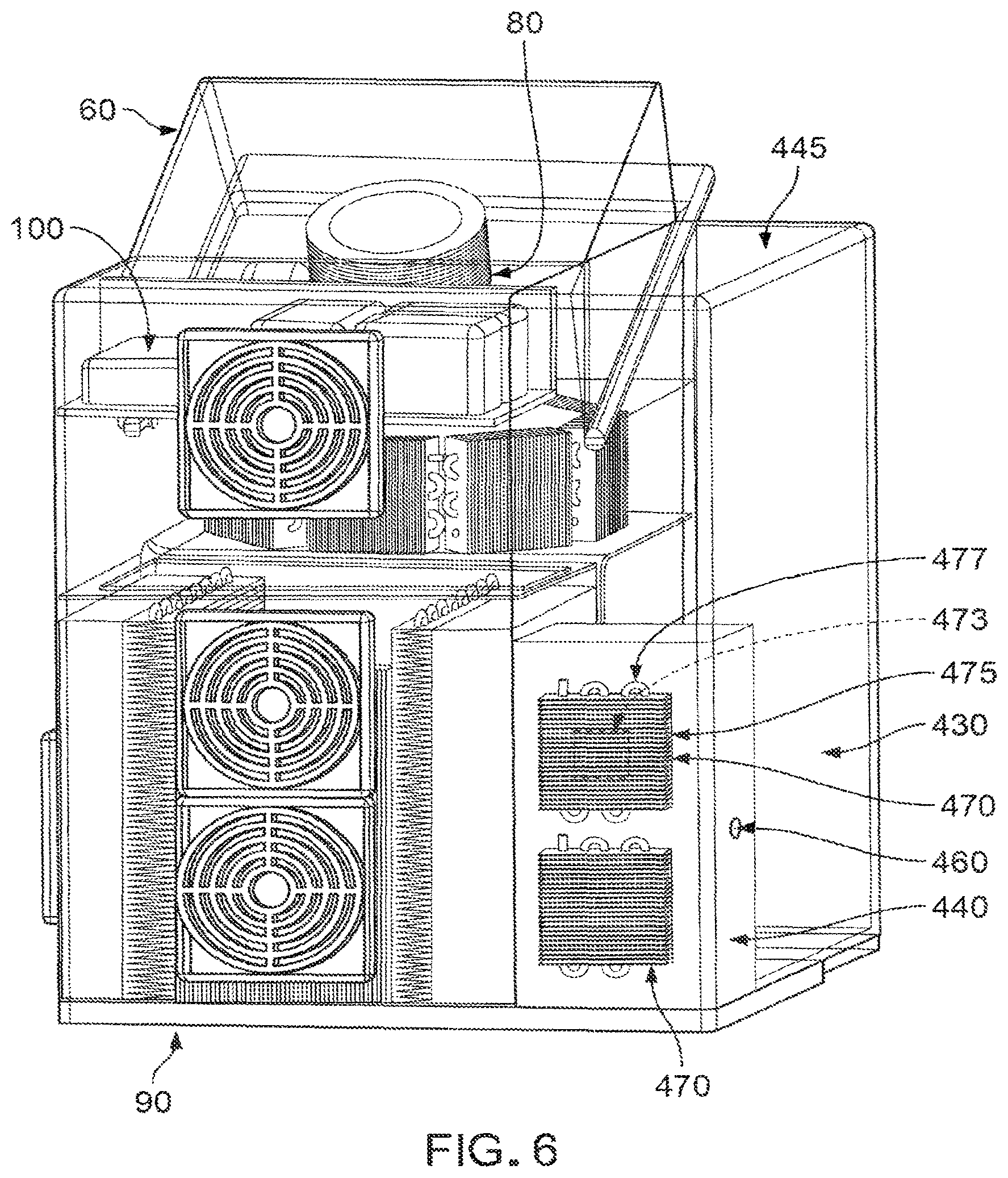
To this end, machine 20 is a reusable device which generally comprises a housing 40, a nest assembly 50, a lid assembly 60, a water supply 70, a cold water and air delivery assembly 80, a heat dissipation assembly 90 and control electronics 100.
Housing 40 is shown in FIGS. 1-6. Housing 40 generally comprises a base 110, a cover 120 mounted to base 110, and a tray 130 mounted to base 110. Cover 120 serves to enclose interior components of machine 20 and to support other components of machine 20. Tray 130 serves to receive a container (e.g., a bowl) into which the frozen confection is to be ejected and from which the frozen confection is to be consumed (alternatively, where the frozen confection is to be consumed from a cone, the cone is held above tray 130).
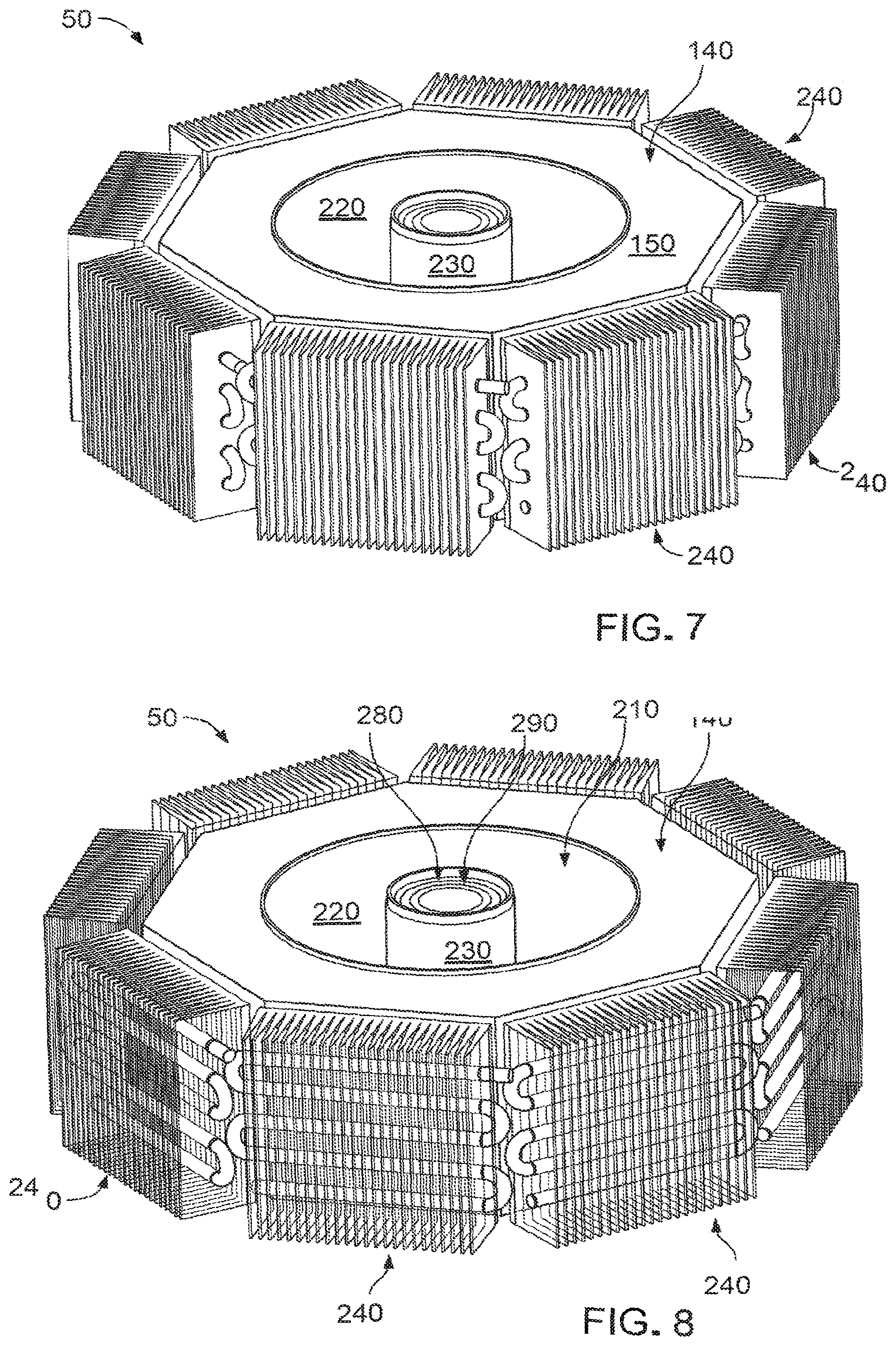
Nest assembly 50 is shown in further detail in FIGS. 7-12. Nest assembly 50 serves to receive a pod 30 containing a supply of ingredients for forming a single serving of the frozen confection and, among other things, rapidly cool pod 30 (and its contents) so as to provide a single serving of a frozen confection in a reduced period of time. To this end, and as will hereinafter be discussed, nest assembly 50 and pod 30 are each provided with a unique configuration and a unique construction so as to speed up cooling of pod 30.
More particularly, nest assembly 50 generally comprises a nest 140 having a top surface 150, a bottom surface 160 and a plurality of outer faces 170. In one preferred form of the invention, nest 140 has eight outer faces 170, so that nest 140 has a generally octagonal configuration. Alternatively, nest 140 may have a different number of outer faces 170. Nest 140 is preferably formed out of a high heat-transfer material such as aluminum.
Nest 140 also comprises a bore 180 and a counterbore 190. A hollow cylinder 200 is disposed in bore 180 and extends upward into counterbore 190. As a result of this construction, an annular recess 210 (i.e., a toroidal recess 210) is formed in top surface 150 of nest 140. Annular recess 210 is generally characterized by an outer wall 220 (which is defined by the aforementioned counterbore 190) and an inner wall 230 (which is defined by the aforementioned hollow cylinder 200). Annular recess 210 is sized to receive pod 30 therein as will hereinafter be discussed.
Nest 140 also comprises a bore 232 which opens on bottom surface 160 of nest 140 and communicates with the interior of annular recess 210. An exit nozzle 233 is mounted to bottom surface 160 of nest 140 at bore 232 so that exit port 234 of exit nozzle 233 communicates with the interior of annular recess 210. A pod sensor 235 is provided in nest 140 to detect when a pod 30 is disposed in annular recess 210 of nest 140.
Nest assembly 50 also comprises a plurality of thermoelectric (TEC) assemblies 240. TEC assemblies 240 each comprise a thermoelectric cooler (TEC) element 250, a heat sink 260 and a plurality of heat pipes 270 extending between TEC element 250 and heat sink 260 so as to transfer heat from TEC element 250 to heat sink 260. If desired, multiple TEC elements 250 can be stacked on each heat sink 260 so as to achieve higher temperature differences than can be had with single-stage TEC elements 250. As seen in FIGS. 7, 8 and 11, TEC assemblies 240 are positioned against outer faces 170 of nest 140 so that TEC elements 250 can provide cold or heat to outer faces 170 of nest 140, depending on the direction of the electric current flow supplied to TEC elements 250, whereby to provide cold or heat to outer wall 220 of annular recess 210 of nest 140 (and hence to provide cold or heat to a pod 30 disposed in annular recess 210 of nest 140). It will be appreciated that when machine 20 is to be used to provide a frozen confection, the direction of the electric current flow supplied to TEC elements 250 causes cold to be applied to outer faces 170 of nest 140.
Heat pipes 270 are preferably of the sort shown in FIG. 12, i.e., they provide a high heat-transfer capacity for transferring heat from TEC elements 250 to heat sinks 260. Heat pipes 270 are preferably also connected to heat dissipation assembly 90 so as to carry the heat collected by heat pipes 270 to heat dissipation assembly 90 for further dissipation to the environment.
Nest assembly 50 also comprises a cylindrical TEC 280 for providing cold to inner wall 230 of annular recess 210, and a cylindrical TEC 290 for supplying heat to inner wall 230 of annular recess 210.
Lid assembly 60 is shown in further detail in FIGS. 13 and 14. Lid assembly 60 generally comprises a handle 300 to which is mounted a lid 310, such that lid 310 moves in conjunction with handle 300. Handle 300 is pivotally mounted to cover 120 of housing 40 via a pivot pin 320. As a result of this construction, lid assembly 60 can pivot towards or away from nest assembly 50 (see FIG. 1). A lid sensor 325 (FIGS. 1 and 2) is provided for detecting when lid 310 is in its closed position.
Lid assembly 60 comprises a plunger 330 which is movably mounted to lid 310. More particularly, plunger 330 comprises a circumferential gear 340 and a longitudinal gear 350, and lid assembly 60 comprises a rotation motor 360 for driving a rotation gear 370 and a vertical motor 380 for driving a vertical gear 390, with rotation gear 370 of rotation motor 360 engaging circumferential gear 340 of plunger 330, and with vertical gear 390 of vertical motor 380 engaging longitudinal gear 350 of plunger 330. As a result of this construction, rotation motor 360 can cause plunger 330 to rotate within lid 310, and vertical motor 380 can cause plunger 330 to move vertically within lid 310.
Plunger 330 further comprises a plurality of fingers 400 for engaging counterpart fingers on pod 30 (see below), and a pair of hollow fangs 410, 420 for penetrating the top of pod 30 and delivering additional ingredients into pod 30 (see below).
Looking next at FIGS. 1-6, water supply 70 generally comprises an ambient-temperature water tank 430 and a cold water tank 440. In one preferred form of the invention, ambient-temperature water tank 430 may hold approximately 2.0 liters of water, and cold water tank 440 may hold approximately 0.5 liter of water. Ambient-temperature water tank 430 comprises a removable cover 445 to enable ambient-temperature water tank 430 to be filled with water. A line (not shown) is provided for moving water from ambient-temperature water tank 430 to cold water tank 440. A water sensor 450 (FIG. 4) is provided for monitoring for the presence of water in ambient-temperature water tank 430, and a water temperature sensor 460 (FIG. 6) is provided for monitoring the temperature of the water in cold water tank 440. A plurality of TEC assemblies 470, each preferably similar to the aforementioned TEC assemblies 240, are provided for chilling the water in cold water tank 440, i.e., TEC assemblies 470 comprise TEC elements 473, heat sinks 475 and heat pipes 477. Heat pipes 477 of TEC assemblies 470 are preferably connected to heat dissipation assembly 90 so as to carry the heat produced by TEC assemblies 470 to heat dissipation assembly 90.
Looking next at FIGS. 6 and 14, cold water and air delivery assembly 80 generally comprises a water pump 480 which pumps cold water from cold water tank 440 into hollow fang 410 of plunger 330, and an air pump 490 which pumps air into hollow fang 420 of plunger 330. In one preferred form of the invention, hollow fang 410 comprises a spray nozzle for injecting droplets of atomized water into pod 30 (see below), whereby to facilitate the formation of the frozen confection (see below). Such spray nozzles are well known in the art of liquid dispersion. Cold water and air delivery assembly 80 also comprises various fluid lines (not shown) for transferring water from cold water tank 440 to hollow fang 410 of plunger 330 and for introducing air into hollow fang 420 of plunger 330.
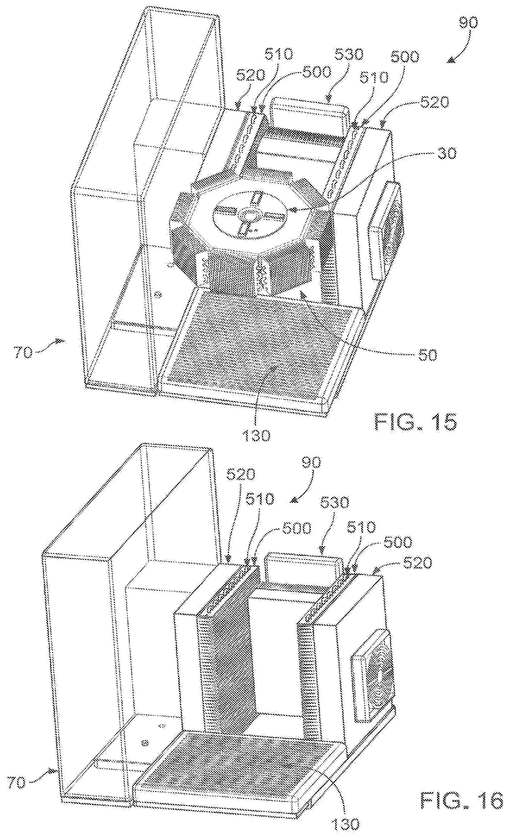
Heat dissipation assembly 90 is shown in further detail in FIGS. 15 and 16. Heat dissipation assembly 90 dissipates heat received from heat pipes 270 of TEC assemblies 240 of nest 140 and dissipates heat received from the heat pipes 477 of TEC assemblies 470 of cold water tank 440. Heat dissipation assembly 90 generally comprises a plurality of heat sinks 500 which draw heat from heat pipes 510 (which are connected to heat pipes 270 of TEC assemblies 240 of nest 140 and heat pipes 477 of TEC assemblies 470 of cold water tank 440), a plurality of condensers 520 for receiving heat from heat sinks 500, and a plurality of fans 530 for cooling condensers 520.
Control electronics 100 generally comprise a power supply 540 (FIG. 14), a central processing unit (CPU) 550 and a user interface 570 (FIG. 2), e.g., a display screen, operating buttons, etc. As seen in FIG. 17, power supply 540 and CPU 550 are connected to the aforementioned water sensor 450, water temperature sensor 460, TEC assemblies 470, cylindrical TEC 280, cylindrical TEC 290, lid sensor 325, pod sensor 235, TEC assemblies 240, water pump 480, air pump 490, rotation motor 360, vertical motor 380, condensers 520, fans 530 and user interface 570. CPU 550 is appropriately programmed to operate machine 20 in response to instructions received from user interface 570 as will hereinafter be discussed.
It will be appreciated that machine 20 is preferably configured to operate at a maximum load of 1800 watts, which is generally the maximum load that standard outlets in a kitchen can handle.
The Pod
Pod 30 contains a supply of ingredients for providing a single serving of a frozen confection (e.g., ice cream, frozen yogurt, a smoothie, etc.). In the preferred form of the invention, pod 30 is provided as a single-use, disposable pod, i.e., a new pod 30 is used for each serving of the frozen confection.
As noted above, and as will hereinafter be discussed, pod 30 is provided with a unique configuration and a unique construction so as to speed up cooling of pod 30 (and its contents), whereby to speed up the process of producing the frozen confection.
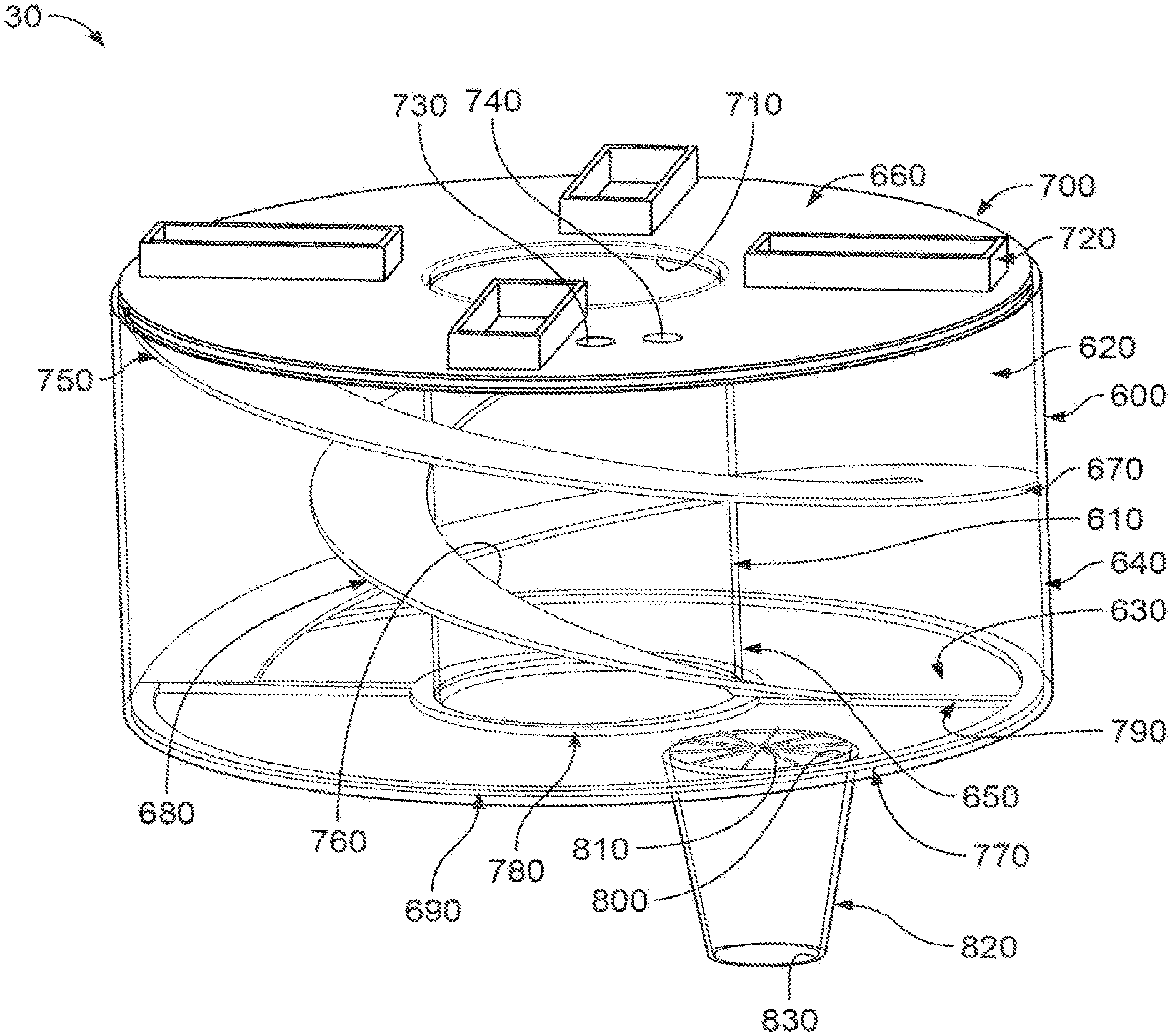
More particularly, and looking now at FIGS. 18-20, pod 30 generally comprises a base 580 having an opening 590 formed therein. An outer hollow tube 600 rises upward from the outer perimeter of base 580, and an inner hollow tube 610 is disposed in opening 590 of base 580 and rises upward from the inner perimeter of base 580. As a result of this construction, an annular recess 620 (i.e., a toroidal recess 620) is formed between base 580, outer hollow tube 600 and inner hollow tube 610, with annular recess 620 being generally characterized by a floor 630 (defined by base 580), an outer wall 640 (defined by outer hollow tube 600) and an inner wall 650 (defined by inner hollow tube 610). Note that the diameter of outer hollow tube 600 of pod 30 is slightly less than the diameter of counterbore 190 of nest 140, and the diameter of inner hollow tube 610 of pod 30 is slightly greater than the diameter of hollow cylinder 200 of nest assembly 50, such that pod 30 can be seated in annular recess 210 of nest 140, with outer hollow tube 600 of pod 30 making a close sliding fit with outer wall 220 of nest 140 and with inner hollow tube 610 of pod 30 making a close sliding fit with inner wall 230 of nest assembly 50.
Preferably base 580 of pod 30 comprises a high heat-transfer material (e.g., aluminum, a molded polymer, etc.), outer hollow tube 600 of pod 30 comprises a high heat-transfer material (e.g., aluminum, a molded polymer, etc.) and inner hollow tube 610 of pod 30 comprises a high heat-transfer material (e.g., aluminum, a molded polymer, etc.). In one preferred form of the invention, base 580, outer hollow tube 600 and inner hollow tube 610 comprise a plastic/thin metallic film composite (i.e., a body of plastic having an external covering of a thin metallic film). It should be appreciated that the plastic/thin metallic film composite allows for improved thermal transfer and helps preserve the contents of pod 30, while also providing pod 30 with a unique packaging appearance. Preferably base 580, outer hollow tube 600 and inner hollow tube 610 are substantially rigid.
Thus it will be seen that, due to the unique configurations and unique constructions of nest assembly 50 and pod 30, when a pod 30 is disposed in the annular recess 210 of nest 140, cold can be efficiently applied to outer wall 640 of pod 30 by outer wall 220 of nest 140, cold can be efficiently applied to inner wall 650 of pod 30 by inner wall 230 of nest assembly 50, and cold can be efficiently applied to base 580 of pod 30 by the floor of annular recess 210 of nest 140. As a result, machine 20 can rapidly cool pod 30 (and its contents) so as to provide a single serving of a frozen confection in a reduced period of time.
Pod 30 also comprises a cap 660, an outer helical scraper paddle 670, an inner helical scraper paddle 680, and a bottom scraper paddle 690.
Cap 660 has an outer edge 700 which is sized slightly smaller than the diameter of outer wall 640 of pod 30, and cap 660 has an inner hole 710 which has a diameter slightly larger than inner hollow tube 610 of pod 30, such that cap 660 can move longitudinally into, and then along, annular recess 620 of pod 30 (see below). Cap 660 is preferably substantially rigid.
Cap 660 also comprises fingers 720 for engaging counterpart fingers 400 of plunger 330, whereby rotational and longitudinal motion can be imparted to cap 660 of pod 30 by plunger 330, as will hereinafter be discussed. Cap 660 also comprises two weakened portions 730, 740 for penetration by hollow fangs 410, 420, respectively, of plunger 330, as will hereinafter be discussed in further detail.
Outer helical scraper paddle 670 extends between cap 660 and bottom scraper paddle 690, and comprises an outer edge 750 which makes a close sliding fit with outer wall 640 of annular recess 620. Inner helical scraper paddle 680 extends between cap 660 and bottom scraper paddle 690, and comprises an inner edge 760 which makes a close sliding fit with inner hollow tube 610 of pod 30. Bottom scraper paddle 690 comprises an outer ring 770 which contacts base 580 and makes a close sliding fit with outer wall 640 of annular recess 620, an inner ring 780 which contacts base 580 and makes a close sliding fit with inner hollow tube 610 of pod 30, and a pair of struts 790 which contact base 580 and extend between outer ring 770 and inner ring 780. As a result of this construction, fingers 720 may be used to turn cap 660 rotationally, such that outer helical scraper paddle 670 rotates, scrapping the interior surface of outer wall 640 of pod 30, inner helical scraper paddle 680 rotates, scraping the exterior surface of inner hollow tube 610, and struts 770 rotate, scraping floor 630 of base 580. It will be appreciated that the provision of outer helical scraper paddle 670, inner helical scraper paddle 680 and bottom scraper paddle 690 is highly advantageous, since outer helical scraper paddle 670, inner helical scraper paddle 680 and bottom scraper paddle 690 can simultaneously (i) agitate the contents of pod 30 so as to ensure uniform and rapid formation of the frozen confection, and (ii) prevent the build-up of frozen confection on base 580, outer hollow tube 600 and inner hollow tube 610, which could inhibit cooling of the contents of pod 30.
Outer helical scraper paddle 670 and inner helical scraper paddle 680 are configured and constructed so that they may be longitudinally compressed by applying a longitudinal force to cap 660, whereby to move cap 660 into, and along, annular recess 620 of pod 30, so as to bring cap 660 substantially into engagement with base 580 (see below). In one preferred form of the invention, outer helical scraper paddle 670 and inner helical scraper paddle 680 are made out of spring steel, with outer helical scrapper paddle 670 and inner helical scraper paddle 680 compressing to substantially flat configurations when a longitudinal force drives cap 660 against base 580 (or, more precisely, substantially against base 580, since the flattened outer helical scraper paddle 670 and the flattened inner helical scraper paddle 680 will be disposed between, and slightly separate, cap 660 from base 580). Bottom scraper paddle 690 may also be formed out of spring steel. In another preferred form of the invention, outer helical scraper paddle 670 and/or inner helical scraper paddle 680 (and/or bottom scraper paddle 690) may be made out of a plastic. If desired, outer helical scraper paddle 670 and/or inner helical scraper paddle 680 (and/or bottom scraper paddle 690) may comprise a shape memory material (e.g., Nitinol).
A bore 800 passes through base 580 and communicates with the interior of annular recess 620. A weakened portion 810 normally closes off bore 800 but may be ruptured upon the application of an appropriate force so as to pass material (e.g., frozen confection) therethrough. An exit nozzle 820 is mounted to base 580 adjacent to bore 800 so that exit port 830 of exit nozzle 820 communicates with the interior of annular recess 620 when weakened portion 810 has been ruptured.
Pod 30 generally has a surface area-to-volume ratio which is greater than 2:1, and which is preferably approximately 8:1. It will be appreciated that increasing the surface area of pod 30 increases the speed of forming the frozen confection in pod 30, since it allows heat to be drawn out of pod 30 (and its contents) more quickly. It will also be appreciated that forming pod 30 with a toroidal configuration (i.e., with both interior and exterior access surfaces) provides increased surface area and enables more rapid cooling of pod 30 and its contents, inasmuch as cold may be simultaneously applied to both the outer surfaces of pod 30 and the inner surfaces of pod 30.
By way of example but not limitation, in one preferred form of the invention, pod 30 has an outer diameter of 2.25 inches and a height of 3.75 inches (i.e., outer hollow tube 600 has an outer diameter of 2.25 inches and a height of 3.75 inches), whereby to provide a surface area of 26.49 square inches and a volume of 14.90 cubic inches; and pod 30 has an inner diameter of 1.4 inches and a height of 3.75 inches (i.e., inner hollow tube 610 has an inner diameter of 1.4 inches and a height of 3.75 inches), whereby to provide a surface area of 16.49 square inches and a volume of 5.77 cubic inches; thereby yielding a total pod surface area of 42.98 square inches (i.e., 26.49 square inches+16.49 square inches=42.98 square inches) and a total pod volume of 9.13 cubic inches (i.e., 14.90 cubic inches-5.77 cubic inches=9.13 cubic inches), and a surface area-to-volume ratio of 8.47:1.
Pod 30 contains a fresh supply of ingredients for forming the frozen confection (e.g., ice cream, frozen yogurt, smoothie, etc.). More particularly, pod 30 may contain a frozen confection mix (dry or liquid) containing, for example, sugar and powder crystals, preferably many of which are less than 50 .mu.m in size, and preferably containing at least 0.1% stabilizers by volume. A dry frozen confection mix preferably has at least 50% of its constituents (e.g., the sugar and powder crystals) having a size of 50 .mu.m or less.
Where pod 30 is to produce a single serving of ice cream, in a preferred form of the invention, pod 30 may hold approximately 4-6 ounces of ingredients, and the ingredients may comprise approximately 8% fat (e.g., cream, butter, anhydrous milk fat, vegetable fat, etc.), approximately 1% milk solids-non-fat (MSNF) (e.g., skim milk power (SMP), whole milk powder (WMP), evaporated milk, condensed milk, etc.), approximately 13% sucrose, approximately 0.5% emulsifier and approximately 0.5% stabilizer.
By way of further example but not limitation, if pod 30 contains 1.25 ounces of dry yogurt mix, 5 ounces of frozen yogurt will be formed in pod 30 after running machine 20.
Use of the System
Looking now at FIG. 21, machine 20 is prepared for use by introducing water into ambient-temperature water tank 430 and turning on machine 20. Water sensor 450 confirms that there is water in ambient-temperature water tank 430. Machine 20 then pumps water from ambient-temperature water tank 430 into cold water tank 440 and chills the water in cold water tank 440 using TEC assemblies 470. Water temperature sensor 460 monitors the temperature of the water in cold water tank 440. Preferably the water in cold water tank 440 is cooled to between approximately 1-3 degrees C. Machine 20 then sits in this standby condition, re-cooling the water in cold water tank 440 as needed, until a single serving of a frozen confection (e.g., ice cream. frozen yogurt, smoothie, etc.) is to be prepared.
When a single serving of a frozen confection is to be prepared, lid assembly 60 of machine 20 is opened and a fresh pod 30 is positioned in annular recess 210 of nest 140. This is done so that exit nozzle 820 of pod 30 seats in exit nozzle 233 of nest 140. Then lid assembly 60 is closed so that fingers 400 of plunger 330 engage fingers 720 of pod 30, and so that hollow fangs 410, 420 of plunger 330 penetrate the two weakened portions 730, 740 of pod 30. In addition, a container (i.e., the container from which the frozen confection will be consumed) is placed on tray 130 of machine 20, with the container being centered below exit nozzle 233 of nest assembly 50 (alternatively, where the frozen confection is to be consumed from a cone, the cone is held above tray 130).
When pod sensor 235 senses the presence of a pod 30 in annular recess 210 of nest 140, machine 20 cools nest assembly 50 via TEC assemblies 240 and cylindrical TEC 280, which in turn cools the pod 30 (and its contents) which is located in annular recess 210 of nest 140. Note that TEC assemblies 240 cool the outer faces 170 of nest 140 so as to cool outer wall 220 of annular recess 210, whereby to cool hollow outer tube 600 of pod 30, and cylindrical TEC 280 cools hollow cylinder 200 so as to cool inner wall 230 of annular recess 210, whereby to cool hollow inner tube 610 of pod 30. Note that the high surface area-to-volume ratio of pod 30, provided by its toroidal configuration, allows for faster cooling of the pod 30 (and its contents). By way of example but not limitation, the contents of pod 30 can be cooled to a temperature of approximately -30 degrees C. so as to form ice cream within 2 minutes (the contents of pod 30 will turn to ice cream at a temperature of -18 degrees C., a lower temperature will produce ice cream even faster). Note also that the heat removed from pod 30 via TEC assemblies 240 and cylindrical TEC 280 is transferred to heat dissipation assembly 90 for dissipation to the environment.
When pod 30 has been appropriately cooled, water pump 480 pumps an appropriate amount of cold water (e.g., at least 1.25 ounces of cold water) from cold water tank 440 into hollow fang 410 in plunger 330, and then through weakened portion 730 in cap 660, so that the cold water is sprayed into the interior of pod 30 and mixes with the contents of pod 30. In a preferred form of the invention, 4 ounces of water at 2 degrees C. is sprayed into pod 30. At the same time, rotation motor 360 rotates plunger 330, whereby to rotate cap 660 of pod 30, which causes outer helical scraper paddle 670, inner helical scraper paddle 680 and bottom scraper paddle 690 to rotate within annular recess 620 of pod 30.
Note that only cap 660, outer helical scraper paddle 670, inner helical scraper paddle 680 and bottom scraper paddle 690 rotate, and the remainder of pod 30 remains stationary, inasmuch as exit nozzle 820 of pod 30 is disposed in exit nozzle 233 of nest assembly 50.
This rotational action agitates the contents of pod 30 so as to ensure uniform and rapid mixing of the contents of pod 30. In addition, this rotational action causes outer helical scraper paddle 670, inner helical scraper paddle 680 and bottom scraper paddle 690 to continuously scrape the walls of pod 30 so as to prevent the build-up of frozen confection on the walls of pod 30 (which could inhibit cooling of the contents of pod 30). Then air pump 490 pumps air into hollow fang 420 in plunger 330, and then through weakened portion 740 in cap 660, so that the air enters the interior of pod 30 and mixes with the contents of pod 30. Preferably enough air is pumped into pod 30 to provide an approximately 30%-50% overrun (i.e., air bubbles) in pod 30, whereby to give the ice cream the desired "loft". As this occurs, outer helical scraper paddle 670, inner helical scraper paddle 680 and bottom scraper paddle 690 continue to agitate the contents of pod 30 so as to ensure uniform and rapid mixing of the contents of pod 30 and so as to continuously scrape the walls of pod 30, whereby to prevent a build-up of frozen confection on the walls of pod 30 (which could inhibit cooling of the contents of pod 30).
In order to create a "smooth" frozen confection, the majority of ice crystals formed in the frozen confection should be smaller than approximately 50 .mu.m. If many of the ice crystals are larger than 50 .mu.m, or if there are extremely large ice crystals (i.e., over 100 .mu.m) present, the frozen confection will be "coarse". System 10 is designed to produce a "smooth" frozen confection by providing a majority of ice crystals smaller than approximately 50 .mu.m.
More particularly, to develop ice crystals with the proper dispersion (number, size and shape), it is necessary to control the freezing process: rates of nucleation vs. growth of crystals. System 10 does this by simultaneously scraping the inner and outer surfaces of annular recess 620 of pod 30. In addition, in order to generate numerous small ice crystals, the freezing conditions within pod 30 must promote nuclei formation and minimize ice crystal growth. Promoting ice nucleation requires very low temperatures, e.g., ideally as low as -30 degrees C., in order to promote rapid nucleation. System 10 freezes the contents of pod 30 very quickly (e.g., under 2 minutes), thereby preventing ice crystals from having the time to "ripen" (i.e., grow). Furthermore, once ice nuclei have formed, conditions that minimize their growth are needed to keep the ice crystals as small as possible. To obtain the smallest possible ice crystals, it is necessary to have the shortest residence time possible in order to minimize "ripening" (i.e., growth) of the ice crystals. System 10 achieves this by using multiple internal scraper paddles to remove ice crystals from the walls of the pod, which helps create high-throughput rates which keeps the ice crystals small (e.g., under 50 .mu.m).
When the frozen confection in pod 30 is ready to be dispensed into the container which has been placed on tray 130 of machine 20 (i.e., the container from which the frozen confection will be consumed), or into a cone held above tray 130, vertical motor 380 moves plunger 330 vertically, causing plunger 330 to force cap 660 of pod 30 downward, toward base 580 of pod 30, with outer helical scraper paddle 670 and inner helical scraper paddle 680 longitudinally compressing with the advance of cap 660. This action reduces the volume of annular recess 620. Vertical motor 380 continues to move plunger 330 vertically, reducing the volume of annular recess 620, until the force of the frozen confection in pod 30 ruptures weakened portion 810 of pod 30 and the frozen confection is forced out exit port 830 of pod 30, whereupon the frozen confection passes through exit port 234 of nest 140 and into the container set on tray 130 (i.e., the container from which the frozen confection will be consumed) or into the cone held above tray 130. This action continues until cap 660 has been forced against base 580, effectively ejecting all of the frozen confection out of pod 30 and into the container from which the ice cream will be consumed.
Thereafter, the used pod 30 may be removed from machine 20 and, when another single serving of a frozen confection is to be prepared, it may be replaced by a fresh pod 30 and the foregoing process repeated.
Alternative Approaches for Cooling the Inner Portion of the Nest Assembly
If desired, and looking now at FIG. 22, cylindrical TEC 280 may be replaced by a helical coil 840 which is itself cooled by a TEC element 850.
Alternatively, if desired, and looking now at FIG. 23, a TEC assembly 240 may be mounted to bottom surface 160 of nest 140 so that TEC assembly 240 can cool hollow cylinder 200 of nest 140 (as well as the bottom surface of nest 140).
Using the System to Provide a Cold Beverage
System 10 can also be used to provide a single serving of a cold beverage. By way of example but not limitation, pod 30 may contain a supply of ingredients for forming cold tea (also sometimes referred to as "iced tea"), cold coffee (also sometimes referred to as "iced coffee"), cold soda, cold beer, etc. In this circumstance, pod 30 may contain a dry or liquid cold tea mix, a dry or liquid cold coffee mix, a dry or liquid soda mix or a dry or liquid beer mix, etc.
Where system 10 is to be used to provide a single serving of a cold beverage, a pod 30, containing a supply of the ingredients used to form the cold beverage, is inserted into nest assembly 50. Nest assembly 50 is then used to cool pod 30, and cold water is pumped from cold water tank 440 into pod 30, where it is combined with the ingredients contained within pod 30, and mixed by outer helical scraper paddle 670, inner helical scraper paddle 680 and bottom scraper paddle 690. When mixing is completed, vertical motor 380 is activated to eject the cold beverage into a waiting container.
It will be appreciated that where a cold beverage is to be produced, air may or may not be pumped into pod 30 (e.g., air may not be pumped into pod 30 when cold tea or cold coffee is being produced, and air may be pumped into pod 30 when cold soda or cold beer is being produced).
It will also be appreciated that where a cold beverage is to be produced, outer helical scraper paddle 670, inner helical scraper paddle 680 and bottom scraper paddle 690 may be omitted from pod 30 if desired.
Using the System to Provide a Hot Beverage
System 10 can also be used to provide a single serving of a hot beverage. By way of example but not limitation, pod 30 may contain a supply of ingredients for forming a hot beverage, e.g., hot chocolate, hot coffee, etc. In this situation, pod 30 may contain a dry mix formed from ingredients which, when mixed with hot water, provide the desired beverage, e.g., a hot chocolate powder, an instant coffee mix, etc.
Where system 10 is to be used to provide a single serving of a hot beverage, a pod 30, containing a supply of the ingredients used to form the hot beverage, is inserted into nest assembly 50. Nest assembly 50 is then used to heat pod 30, and ambient-temperature water is pumped from ambient-temperature water tank 430 into pod 30, where it is combined with the ingredients contained within pod 30, and mixed by outer helical scraper paddle 670, inner helical scraper paddle 680 and bottom scraper paddle 690. Note that TEC assemblies 240 may be used to supply heat to the outer surfaces of nest 140 by simply reversing the direction of the electric current flow supplied to TEC elements 250, and cylindrical TEC 290 may be used to supply heat to the inner column of nest 140, whereby to heat the contents of pod 30. In addition, if desired, the ambient-temperature water in ambient-temperature water tank 430 may be heated before injection into pod 30, e.g., via resistance heaters positioned in the line between ambient-temperature water tank 430 and hollow fang 410 of plunger 330. It will be appreciated that where a hot beverage is to be produced, air is generally not pumped into pod 30.
In many cases, it may be desirable to "brew" a hot beverage by passing water through a supply of granulated ingredients, e.g., such as in the case of coffee or tea. To that end, and looking now at FIGS. 24-27, pod 30 can be provided with a filter 860 which contains a supply of the granulated ingredients (e.g., ground coffee beans, tea leaves, etc.) which is to be brewed. In one preferred form of the invention, and as shown in FIGS. 24-27, filter 860 is disposed adjacent to cap 660, e.g., filter 860 is secured to cap 660, and outer helical scraper paddle 670, inner helical scraper paddle 680 and bottom scraper paddle 690 are omitted from pod 30. Note also that when plunger 330 collapses cap 660 towards base 580, filter 860 will preferably also collapse, whereby to allow compression of the granulated ingredients contained within filter 860, so as to press the fluid out of filter 860, e.g., in the manner of a so-called "French Press" coffee maker. It should also be appreciated that filter 860 is constructed so that it will maintain its structural integrity during collapse so that the granulated contents of filter 860 do not pass out of pod 30.
Alternative Configuration
If desired, and looking now at FIG. 28, machine 20 can be mounted to a cabinet 870, where cabinet 870 sits on legs 880. In this construction, cabinet 870 can include additional cooling apparatus for removing heat from heat dissipation assembly 90 (e.g., additional heat pipes, condensers and fans, or a conventional refrigeration unit, etc.). Cabinet 870 may also be configured so as to house fresh pods 30 and/or containers for receiving the frozen confections (e.g., bowls and cones), cold beverages (e.g., cups) and hot beverages (e.g., cups).
Chilling the Pod with a Refrigeration Coil
In another form of the invention, and looking now at FIGS. 29-31, nest assembly 50 may be replaced by an alternative nest assembly 50A comprising a nest 140A in the form of a torus characterized by an outer wall 220A and an inner wall 230A, wherein the torus is formed out of a high heat-transfer material (e.g., aluminum), and further wherein TEC assemblies 240 are replaced by a refrigeration coil 240A which is connected to heat dissipation assembly 90A, wherein heat dissipation assembly 90A comprises a compressor for driving refrigeration coil 240A. It will be appreciated that, as a result of this construction, nest assembly 50A (and hence a pod 30 disposed in nest assembly 50A) can be cooled via a conventional refrigeration system. This construction can be advantageous since it can quickly cool a pod 30 to -40 degrees C., which is beyond the thermal performance of TEC elements 250.
Alternative Nest and Pod Constructions
In the foregoing disclosure, nest assembly 50 and nest assembly 50A comprise an internal cooling element (e.g., hollow cylinder 200 containing TEC 280) as well as external cooling elements (e.g., TEC assemblies 240), and pod 30 comprises an inner opening (i.e., the lumen of inner hollow tube 610) for receiving the internal cooling element of nest assemblies 50 and 50A. However, if desired, the internal cooling element may be omitted from nest assemblies 50 and 50A, in which case the inner opening of pod 30 may also be omitted.
Alternative Pod Constructions
The ice cream mix pods can be made of plastic by injection molding process. These pods can be lined with a thin film of sputtered or physical vapor deposition (PVD) metal layer for enhanced cooling/freezing efficiencies. This sputter technology is often used to line food packaging products such as the metal liner inside potato chip bags to help keep the mix dry and fresh.
FIG. 32 shows the single serve pods or cartridges which can be made with a frustoconical, conical, or funnel shaped container to enhance the mixing action while rotating. This funnel shape pod will also facilitate the pouring or flow of the soft serve ice cream into the cone or cup below it. The funnel shaped pod can have an extended nipple or port further guiding/directing the pouring action of the soft serve ice cream as it is dispensed. Ideally the ice cream is expended from the funnel shaped pod, thru its nozzle, nipple or port and is either pushed or falls with gravity directly into the ice cream cone below without touching any of the machine's parts so to minimize or eliminate the need to clean the machine between servings. The nozzle, nipple or port can be shaped, i.e. like a star to give a star-shape to the single serve ice cream as it piles into a cone or dish. This exit nipple or port can be a spray nozzle which combines the mixture of dry ice cream mix, water and cold air from compressed air forced thru a vortex lube.
Modifications of the Preferred Embodiments
It should be understood that many additional changes in the details, materials, steps and arrangements of parts, which have been herein described and illustrated in order to explain the nature of the present invention, may be made by those skilled in the art while still remaining within the principles and scope of the invention.
* * * * *
D00000
D00001
D00002
D00003
D00004
D00005
D00006
D00007
D00008
D00009
D00010
D00011
D00012

D00013

D00014

D00015
D00016
D00017

D00018

D00019

D00020

XML
uspto.report is an independent third-party trademark research tool that is not affiliated, endorsed, or sponsored by the United States Patent and Trademark Office (USPTO) or any other governmental organization. The information provided by uspto.report is based on publicly available data at the time of writing and is intended for informational purposes only.
While we strive to provide accurate and up-to-date information, we do not guarantee the accuracy, completeness, reliability, or suitability of the information displayed on this site. The use of this site is at your own risk. Any reliance you place on such information is therefore strictly at your own risk.
All official trademark data, including owner information, should be verified by visiting the official USPTO website at www.uspto.gov. This site is not intended to replace professional legal advice and should not be used as a substitute for consulting with a legal professional who is knowledgeable about trademark law.