Filter with variable cross-section axial seal
Tofsland June 1, 2
U.S. patent number 11,020,698 [Application Number 15/781,585] was granted by the patent office on 2021-06-01 for filter with variable cross-section axial seal. This patent grant is currently assigned to CUMMINS FILTRATION IP, INC.. The grantee listed for this patent is Cummins Filtration IP, Inc.. Invention is credited to Ken Tofsland.
| United States Patent | 11,020,698 |
| Tofsland | June 1, 2021 |
Filter with variable cross-section axial seal
Abstract
Filtration systems having filter elements having an axial seal member with a variable cross-section are described. The variable cross-section is matched by the non-planar sealing surfaces of the housing and housing cover that receive the filter elements. The non-planar sealing surfaces of the housing and the housing cover prevent proper filtration system function when an unauthorized replacement filter element having a flat axial seal member is installed in the housing.
| Inventors: | Tofsland; Ken (Stoughton, WI) | ||||||||||
|---|---|---|---|---|---|---|---|---|---|---|---|
| Applicant: |
|
||||||||||
| Assignee: | CUMMINS FILTRATION IP, INC.
(Columbus, IN) |
||||||||||
| Family ID: | 1000005587726 | ||||||||||
| Appl. No.: | 15/781,585 | ||||||||||
| Filed: | November 21, 2016 | ||||||||||
| PCT Filed: | November 21, 2016 | ||||||||||
| PCT No.: | PCT/US2016/063053 | ||||||||||
| 371(c)(1),(2),(4) Date: | June 05, 2018 | ||||||||||
| PCT Pub. No.: | WO2017/099984 | ||||||||||
| PCT Pub. Date: | June 15, 2017 |
Prior Publication Data
| Document Identifier | Publication Date | |
|---|---|---|
| US 20200261837 A1 | Aug 20, 2020 | |
Related U.S. Patent Documents
| Application Number | Filing Date | Patent Number | Issue Date | ||
|---|---|---|---|---|---|
| 62266219 | Dec 11, 2015 | ||||
| Current U.S. Class: | 1/1 |
| Current CPC Class: | B01D 46/2411 (20130101); B01D 46/0005 (20130101); B01D 2279/60 (20130101); B01D 2271/022 (20130101); F02M 35/02416 (20130101) |
| Current International Class: | B01D 46/00 (20060101); B01D 46/24 (20060101); F02M 35/024 (20060101) |
References Cited [Referenced By]
U.S. Patent Documents
| 2093877 | September 1937 | Von Pentz |
| 2270969 | January 1942 | Robinson |
| 2306325 | December 1942 | Allam |
| 2910332 | October 1959 | Madsen |
| 2915188 | December 1959 | Buker |
| 2955028 | October 1960 | Bevans |
| 3025963 | March 1962 | Bauer |
| 3224592 | December 1965 | Burns |
| 3383841 | May 1968 | Olson |
| 3494113 | February 1970 | Kinney |
| 3576095 | April 1971 | Rivers |
| 3582095 | June 1971 | Bogaert et al. |
| 3598738 | August 1971 | Biswell et al. |
| 3645402 | February 1972 | Alexander et al. |
| 3687849 | August 1972 | Abbott |
| 3749247 | July 1973 | Rohde |
| 4014794 | March 1977 | Lewis |
| 4061572 | December 1977 | Cohen et al. |
| 4066559 | January 1978 | Rohde |
| 4075097 | February 1978 | Paul |
| 4075098 | February 1978 | Paul et al. |
| 4080185 | March 1978 | Richter et al. |
| 4129429 | December 1978 | Humbert et al. |
| 4144169 | March 1979 | Grueschow |
| 4181313 | January 1980 | Hillier |
| 4211543 | July 1980 | Tokar et al. |
| 4300928 | November 1981 | Sugie |
| 4324213 | April 1982 | Kasting et al. |
| 4364751 | December 1982 | Copley |
| 4402912 | September 1983 | Krueger et al. |
| 4410427 | October 1983 | Wydeven |
| 4572522 | February 1986 | Smagatz |
| 4589983 | May 1986 | Wydevan |
| 4600420 | July 1986 | Wydeven et al. |
| 4617122 | October 1986 | Kruse et al. |
| 4738776 | April 1988 | Brown |
| 4755289 | July 1988 | Villani |
| 4782891 | November 1988 | Cheadle et al. |
| 4826517 | May 1989 | Norman |
| 4861359 | August 1989 | Tettman |
| 4865636 | September 1989 | Raber |
| 4915831 | April 1990 | Taylor |
| 4925561 | May 1990 | Ishii et al. |
| 4979969 | December 1990 | Herding |
| 5024268 | June 1991 | Cheadle et al. |
| 5050549 | September 1991 | Sturmon |
| 5069799 | December 1991 | Brownawell et al. |
| 5094745 | March 1992 | Reynolds |
| 5120334 | June 1992 | Cooper |
| 5213596 | May 1993 | Kume et al. |
| 5222488 | June 1993 | Forsgren |
| 5223011 | June 1993 | Hanni |
| 5225081 | July 1993 | Brownawell |
| 5258118 | November 1993 | Gouritin et al. |
| 5298160 | March 1994 | Ayers et al. |
| 5342511 | August 1994 | Brown et al. |
| 5382355 | January 1995 | Arlozynski |
| 5391212 | February 1995 | Ernst et al. |
| 5435346 | July 1995 | Tregidgo et al. |
| 5459074 | October 1995 | Muoni |
| 5472379 | December 1995 | Andress et al. |
| 5472463 | December 1995 | Herman et al. |
| 5484466 | January 1996 | Brown et al. |
| 5494497 | February 1996 | Lee |
| 5498332 | March 1996 | Handtmann |
| 5512074 | April 1996 | Hanni et al. |
| 5531848 | July 1996 | Brinda et al. |
| 5556542 | September 1996 | Berman et al. |
| 5560330 | October 1996 | Andress et al. |
| 5562825 | October 1996 | Yamada et al. |
| 5569311 | October 1996 | Oda et al. |
| 5575826 | November 1996 | Gillingham et al. |
| 5591330 | January 1997 | Lefebvre |
| 5605554 | February 1997 | Kennedy |
| 5662799 | September 1997 | Hudgens et al. |
| 5672399 | September 1997 | Kahlbaugh et al. |
| 5709722 | January 1998 | Nagai et al. |
| 5720790 | February 1998 | Kometani |
| 5738785 | April 1998 | Brown et al. |
| 5753116 | May 1998 | Baumann et al. |
| 5759217 | June 1998 | Joy |
| 5772883 | June 1998 | Rothman et al. |
| 5795361 | August 1998 | Lanier et al. |
| 5803024 | September 1998 | Brown |
| 5820646 | October 1998 | Gillingham et al. |
| 5853439 | December 1998 | Gieseke et al. |
| 5863424 | January 1999 | Lee |
| 5891402 | April 1999 | Sassa et al. |
| 5893939 | April 1999 | Rakocy et al. |
| 5902364 | May 1999 | Tokar et al. |
| 5948248 | September 1999 | Brown |
| 6045692 | April 2000 | Bilski et al. |
| D425189 | May 2000 | Gillingham et al. |
| 6086763 | July 2000 | Baumann |
| 6096208 | August 2000 | Connelly et al. |
| 6098575 | August 2000 | Mulshine et al. |
| 6129852 | October 2000 | Elliott et al. |
| 6149700 | November 2000 | Morgan et al. |
| 6171355 | January 2001 | Gieseke et al. |
| 6179890 | January 2001 | Ramos et al. |
| D437402 | February 2001 | Gieseke et al. |
| 6190432 | February 2001 | Gieseke et al. |
| 6196019 | March 2001 | Higo et al. |
| 6217627 | April 2001 | Vyskocil et al. |
| 6231630 | May 2001 | Ernst et al. |
| 6235194 | May 2001 | Jousset |
| 6235195 | May 2001 | Tokar |
| 6238554 | May 2001 | Martin et al. |
| 6238561 | May 2001 | Liu et al. |
| 6261334 | July 2001 | Morgan et al. |
| 6264833 | July 2001 | Reamsnyder et al. |
| RE37369 | September 2001 | Hudgens et al. |
| 6293984 | September 2001 | Oda et al. |
| 6306193 | October 2001 | Morgan et al. |
| D450828 | November 2001 | Tokar |
| 6348085 | February 2002 | Tokar et al. |
| D455826 | April 2002 | Gillingham et al. |
| 6375700 | April 2002 | Jaroszczyk et al. |
| 6379564 | April 2002 | Rohrbach et al. |
| 6391076 | May 2002 | Jaroszczyk et al. |
| 6398832 | June 2002 | Morgan et al. |
| 6402798 | June 2002 | Kallsen et al. |
| 6416561 | July 2002 | Kallsen et al. |
| 6447566 | September 2002 | Rivera et al. |
| 6475379 | November 2002 | Jousset et al. |
| 6478018 | November 2002 | Fedorowicz et al. |
| 6478019 | November 2002 | Fedorowicz et al. |
| 6478958 | November 2002 | Beard et al. |
| 6482247 | November 2002 | Jaroszczyk et al. |
| 6511599 | January 2003 | Jaroszczyk et al. |
| 6517598 | February 2003 | Anderson et al. |
| 6537453 | March 2003 | Beard et al. |
| D473637 | April 2003 | Golden |
| 6547857 | April 2003 | Gieseke et al. |
| 6554139 | April 2003 | Maxwell et al. |
| 6596165 | July 2003 | Koivula |
| 6610126 | August 2003 | Xu et al. |
| 6623636 | September 2003 | Rohrbach et al. |
| 6641637 | November 2003 | Kallsen et al. |
| 6673136 | January 2004 | Gillingham et al. |
| 6676721 | January 2004 | Gillingham et al. |
| 6709588 | March 2004 | Pavlin et al. |
| 6743317 | June 2004 | Wydeven |
| 6746518 | June 2004 | Gieseke et al. |
| 6787033 | September 2004 | Beard et al. |
| 6827750 | December 2004 | Drozd et al. |
| 6835304 | December 2004 | Jousset et al. |
| 6837920 | January 2005 | Gieseke et al. |
| 6843916 | January 2005 | Burrington et al. |
| 6860241 | March 2005 | Martin et al. |
| 6893571 | May 2005 | Harenbrock et al. |
| 6902598 | June 2005 | Gunderson et al. |
| 6919023 | July 2005 | Merritt et al. |
| 6953124 | October 2005 | Winter et al. |
| 6966940 | November 2005 | Krisko et al. |
| 6969461 | November 2005 | Beard et al. |
| 6984319 | January 2006 | Merritt et al. |
| 6996940 | February 2006 | Beasley |
| 7001450 | February 2006 | Gieseke et al. |
| 7008467 | March 2006 | Krisko et al. |
| 7018531 | March 2006 | Eilers et al. |
| 7048501 | May 2006 | Katayama et al. |
| 7076641 | July 2006 | Gunderson et al. |
| 7081145 | July 2006 | Gieseke et al. |
| 7090711 | August 2006 | Gillingham et al. |
| 7153422 | December 2006 | Herman et al. |
| 7156991 | January 2007 | Herman et al. |
| 7160451 | January 2007 | Hacker et al. |
| 7182863 | February 2007 | Eilers et al. |
| 7182864 | February 2007 | Brown et al. |
| 7211124 | May 2007 | Gieseke et al. |
| 7217361 | May 2007 | Connor et al. |
| 7247183 | July 2007 | Connor et al. |
| 7258719 | August 2007 | Miller et al. |
| 7282075 | October 2007 | Sporre et al. |
| 7311747 | December 2007 | Adamek et al. |
| 7338544 | March 2008 | Sporre et al. |
| 7351270 | April 2008 | Engelland et al. |
| 7396375 | July 2008 | Nepsund et al. |
| 7425226 | September 2008 | Powell |
| 7491254 | February 2009 | Krisko et al. |
| 7494017 | February 2009 | Miller |
| 7524416 | April 2009 | Bergmen |
| 7540895 | June 2009 | Furseth et al. |
| D600790 | September 2009 | Nelson et al. |
| 7582130 | September 2009 | Ng et al. |
| 7625419 | December 2009 | Nelson et al. |
| 7645310 | January 2010 | Krisko et al. |
| 7655074 | February 2010 | Nepsund et al. |
| 7674308 | March 2010 | Krisko et al. |
| 7682416 | March 2010 | Engelland et al. |
| 7776139 | August 2010 | Schwandt et al. |
| 7799108 | September 2010 | Connor et al. |
| 7828869 | November 2010 | Parikh et al. |
| 7931723 | April 2011 | Cuvelier |
| 7959714 | June 2011 | Smith et al. |
| 7967886 | June 2011 | Schrage et al. |
| 7972405 | July 2011 | Engelland et al. |
| 7981183 | July 2011 | Nepsund et al. |
| 7993422 | August 2011 | Krisko et al. |
| 8016903 | September 2011 | Nelson et al. |
| 8034145 | October 2011 | Boehrs et al. |
| 8048187 | November 2011 | Merritt et al. |
| 8061530 | November 2011 | Kindkeppel et al. |
| 8062399 | November 2011 | Nelson et al. |
| 8101003 | January 2012 | Krisko et al. |
| 8119002 | February 2012 | Schiavon et al. |
| 8241383 | August 2012 | Schrage et al. |
| 8277532 | October 2012 | Reichter et al. |
| 8292983 | October 2012 | Reichter et al. |
| 8328897 | December 2012 | Nelson et al. |
| 8357219 | January 2013 | Boehrs et al. |
| 8480779 | July 2013 | Boehrs et al. |
| 8496723 | July 2013 | Reichter et al. |
| 8518141 | August 2013 | Schrage et al. |
| 8562707 | October 2013 | Nepsund et al. |
| 8636820 | January 2014 | Reichter et al. |
| 8652228 | February 2014 | Krisko et al. |
| 8709119 | April 2014 | Reichter et al. |
| 8753414 | June 2014 | Gebert |
| 8778043 | July 2014 | Krisko et al. |
| 8840699 | September 2014 | Bruce et al. |
| 8852308 | October 2014 | Jarrier |
| 8906128 | December 2014 | Reichter et al. |
| 8926725 | January 2015 | Loken et al. |
| 9114346 | August 2015 | Schrage et al. |
| 9320997 | April 2016 | Campbell et al. |
| 9415333 | August 2016 | Kindkeppel et al. |
| 9782708 | October 2017 | Kindkeppel et al. |
| 10729999 | August 2020 | Nichols et al. |
| 10744443 | August 2020 | Silvestro |
| 10835852 | November 2020 | Decoster et al. |
| 2001/0032545 | October 2001 | Goto et al. |
| 2002/0046556 | April 2002 | Reid |
| 2002/0060178 | May 2002 | Tsabari |
| 2002/0073850 | June 2002 | Tokar et al. |
| 2002/0096247 | July 2002 | Wydeven |
| 2002/0157359 | October 2002 | Stenersen et al. |
| 2002/0170280 | November 2002 | Soh |
| 2002/0185007 | December 2002 | Xu et al. |
| 2002/0185454 | December 2002 | Beard et al. |
| 2002/0195384 | December 2002 | Rohrbach et al. |
| 2003/0121845 | July 2003 | Wagner et al. |
| 2003/0154863 | August 2003 | Tokar et al. |
| 2003/0184025 | October 2003 | Matsuki |
| 2003/0218150 | November 2003 | Blakemore et al. |
| 2004/0035097 | February 2004 | Schlensker et al. |
| 2004/0040271 | March 2004 | Kopec et al. |
| 2004/0060861 | April 2004 | Winter et al. |
| 2004/0091652 | May 2004 | Kikuchi et al. |
| 2004/0091654 | May 2004 | Kelly et al. |
| 2004/0140255 | July 2004 | Merritt et al. |
| 2004/0173097 | September 2004 | Engelland et al. |
| 2004/0187689 | September 2004 | Sporre et al. |
| 2004/0221555 | November 2004 | Engelland et al. |
| 2004/0226443 | November 2004 | Gillingham et al. |
| 2005/0019236 | January 2005 | Martin et al. |
| 2005/0024061 | February 2005 | Cox et al. |
| 2005/0166561 | August 2005 | Schrage et al. |
| 2005/0173325 | August 2005 | Klein et al. |
| 2005/0194312 | September 2005 | Niemeyer et al. |
| 2005/0224061 | October 2005 | Ulrich et al. |
| 2005/0252848 | November 2005 | Miller |
| 2006/0064956 | March 2006 | Connor et al. |
| 2006/0113233 | June 2006 | Merritt et al. |
| 2006/0180537 | August 2006 | Loftis et al. |
| 2006/0213139 | September 2006 | Stramandinoli |
| 2007/0175815 | August 2007 | Thomas |
| 2007/0240392 | October 2007 | Ng et al. |
| 2007/0261374 | November 2007 | Nelson et al. |
| 2008/0011672 | January 2008 | Schwartz et al. |
| 2008/0022641 | January 2008 | Engelland et al. |
| 2008/0087589 | April 2008 | Grzonka et al. |
| 2008/0107765 | May 2008 | Considine et al. |
| 2008/0110142 | May 2008 | Nelson et al. |
| 2008/0250766 | October 2008 | Schrage et al. |
| 2008/0307759 | December 2008 | Reichter et al. |
| 2009/0057213 | March 2009 | Schiavon et al. |
| 2009/0064646 | March 2009 | Reichter et al. |
| 2009/0090669 | April 2009 | Holzmann et al. |
| 2009/0126324 | May 2009 | Smith et al. |
| 2009/0151311 | June 2009 | Reichter et al. |
| 2009/0193972 | August 2009 | Schwandt et al. |
| 2010/0043366 | February 2010 | Boehrs et al. |
| 2010/0051528 | March 2010 | Derstler et al. |
| 2010/0064646 | March 2010 | Smith et al. |
| 2010/0065203 | March 2010 | Tanbour et al. |
| 2010/0077710 | April 2010 | Severance et al. |
| 2010/0170209 | July 2010 | Nelson et al. |
| 2010/0186353 | July 2010 | Ackermann et al. |
| 2010/0258493 | October 2010 | Kindkeppel |
| 2010/0263339 | October 2010 | Steins et al. |
| 2011/0197556 | August 2011 | Brown et al. |
| 2012/0055127 | March 2012 | Holzmann et al. |
| 2012/0061307 | March 2012 | Kindkeppel et al. |
| 2012/0223008 | September 2012 | Mbadinga-Mouanda et al. |
| 2014/0034565 | February 2014 | Loken et al. |
| 2014/0096493 | April 2014 | Kelmartin et al. |
| 2014/0151275 | June 2014 | Bradford et al. |
| 2014/0251895 | September 2014 | Wagner |
| 2014/0260143 | September 2014 | Kaiser |
| 2014/0290194 | October 2014 | Muenkel et al. |
| 2014/0318090 | October 2014 | Rieger et al. |
| 2015/0013289 | January 2015 | Hasenfratz et al. |
| 2015/0013293 | January 2015 | Wagner et al. |
| 2015/0033684 | February 2015 | Pettersson |
| 2015/0061307 | March 2015 | Nakanishi |
| 2015/0096273 | April 2015 | Kaiser |
| 2015/0176544 | June 2015 | Kaufmann et al. |
| 2016/0045848 | February 2016 | Campbell et al. |
| 2016/0059172 | March 2016 | Allott et al. |
| 2017/0078852 | March 2017 | Tan et al. |
| 2018/0318745 | November 2018 | Nichols |
| 2020/0324237 | October 2020 | Moers et al. |
| 2296402 | Nov 1998 | CN | |||
| 2372041 | Apr 2000 | CN | |||
| 1486213 | Mar 2004 | CN | |||
| 1590746 | Mar 2005 | CN | |||
| 1754612 | Apr 2006 | CN | |||
| 101084050 | Dec 2007 | CN | |||
| 101374582 | Feb 2009 | CN | |||
| 201292900 | Aug 2009 | CN | |||
| 101695616 | Apr 2010 | CN | |||
| 102271780 | Dec 2011 | CN | |||
| 202746046 | Feb 2013 | CN | |||
| 103977647 | Aug 2014 | CN | |||
| 104220142 | Dec 2014 | CN | |||
| 88 08 632 | Sep 1988 | DE | |||
| 29613098 | Sep 1996 | DE | |||
| 10 2008 062 956 | Dec 2008 | DE | |||
| 10 2008 062 956 | Jun 2010 | DE | |||
| 0 747 579 | Dec 1996 | EP | |||
| 0 982 062 | Mar 2000 | EP | |||
| 1 129 760 | Sep 2001 | EP | |||
| 1 166 843 | Jan 2002 | EP | |||
| 1 208 902 | May 2002 | EP | |||
| 1 233 173 | Aug 2002 | EP | |||
| 1 747 053 | Jan 2007 | EP | |||
| 3 370 849 | Sep 2018 | EP | |||
| 2214505 | Aug 1974 | FR | |||
| 0 970 826 | Sep 1964 | GB | |||
| 2 082 932 | Mar 1982 | GB | |||
| 2 404 348 | Feb 2005 | GB | |||
| 60-112320 | Jun 1985 | JP | |||
| 01-163408 | Jun 1989 | JP | |||
| 01-171615 | Jul 1989 | JP | |||
| 02-025009 | Jan 2002 | JP | |||
| WO-00/50152 | Aug 2000 | WO | |||
| WO-00/74818 | Dec 2000 | WO | |||
| WO 2004/054684 | Jul 2004 | WO | |||
| WO-2005/058461 | Jun 2005 | WO | |||
| WO-2005/077487 | Aug 2005 | WO | |||
| WO-2007/009039 | Jan 2007 | WO | |||
| WO 2007/089662 | Aug 2007 | WO | |||
| WO-2017/079191 | May 2017 | WO | |||
Other References
|
First Office Action issued for German Patent Application No. 11 2010 001 567.8, including English language translation, dated May 18, 2017, 6 pages. cited by applicant . International Search Report and Written Opinion issued for PCT/US2017/030386, dated Jul. 26, 2017, 9 pages. cited by applicant . First Office Action issued for German Patent Application No. 11 2010 001 567.8, including English language translation, dated May 18, 2017, 12 pages. cited by applicant . First Office Action issued for Chinese Patent Applicaton No. CN 2016800710703 dated Nov. 26, 2020, with translation, 19 pages. cited by applicant . International Search Report and Written Opinion for PCT/US2017/021615, dated Jun. 6, 2017, 8 pages. cited by applicant . International Search Report and Written Opinion issued for PCT/US2016/063053, dated Feb. 16, 2017, 8 pages. cited by applicant . Akro-Mils, "Nest & Stack Totes," retrieved from http://web.archive.org/web/20150323114331/https://akro-mils.com/produts/t- ypes/plastic-storage-containers/nest-stack-totes, 1 page (2015). cited by applicant . Final Office Action on U.S. Appl. No. 16/097,773 dated Dec. 14, 2020. cited by applicant . Non-Final Office Action on U.S. Appl. No. 16/083,945 dated Nov. 10, 2020. cited by applicant . Non-Final Office Action from U.S. Appl. No. 16/097,773, dated Jul. 14, 2020. cited by applicant . First Office Action issued for Chinese Patent Application No. CN201880018033.5 dated Dec. 24, 2020, 10 pages. cited by applicant. |
Primary Examiner: Clemente; Robert
Attorney, Agent or Firm: Foley & Lardner LLP
Parent Case Text
CROSS-REFERENCE TO RELATED APPLICATIONS
This application is related to and claims priority to U.S. Provisional Patent Application No. 62/266,219, entitled "FILTER WITH VARIABLE CROSS-SECTION AXIAL SEAL," by Tofsland, filed on Dec. 11, 2015, the contents of which are herein incorporated by reference in their entirety and for all purposes.
Claims
What is claimed is:
1. A filtration system, comprising: a housing defining a central compartment therein, the housing including an outlet and a housing sealing surface, the housing sealing surface being non-planar; a cover removably coupled to the housing, the cover including an inlet and a cover sealing surface; and a filter element positioned within the central compartment of the housing, the filter element including filter media and a seal member coupled to the filter media and circumscribing at least a portion of the filter media, the seal member including a first sealing surface and a second sealing surface, the first sealing surface has an arc-shaped profile extending from a first end of the seal member to a second end of the seal member, the second sealing surface has an opposite arc-shaped profile extending from the first end of the seal member to the second end of the seal member, each arc-shaped profile defines a convex arc shape comprising a continuous curve between the first end and the second end, the seal member having a variable cross-section such that, at a perimetral distance from the filter media, an axial distance between the first sealing surface and the second sealing surface varies along at least a portion of the seal member, the variable cross-section being complementary to the housing sealing surface and the cover sealing surface such that the seal member forms an axial seal between the housing and the cover when the filter element is installed in the air filtration system.
2. The system of claim 1, wherein each arc-shaped profile has a height that is smaller than a span distance such that a ratio of the span distance to the height is greater than 10 to 1.
3. The system of claim 2, wherein the ratio of the span distance to the height is greater than 50 to 1.
4. The system of claim 2, wherein the opposite arc-shaped profile extends the span distance and has the height that is smaller than the span distance.
5. The system of claim 4, wherein the cover sealing surface is non-planar.
6. The system of claim 1, wherein the filter element is a cylindrical filter element, and wherein the seal member is ring shaped.
7. The system of claim 1, wherein the seal member is substantially rectangular in shape.
8. The system of claim 1, and wherein the distance between the first sealing surface and the second sealing surface varies along only one of four sides of the seal member.
9. The system of claim 1, and wherein the distance between the first sealing surface and the second sealing surface varies along at least two of four sides of the seal member.
10. The system of claim 1, wherein the first sealing surface and the second sealing surface are on opposing sides of the seal member.
11. A filter element comprising: filter media; and a seal member coupled to the filter media and circumscribing at least a portion of the filter media, the seal member comprising a first sealing surface and a second sealing surface, the first sealing surface has an arc-shaped profile extending from a first end of the seal member to a second end of the seal member, the second sealing surface has an opposite arc-shaped profile extending from the first end of the seal member to the second end of the seal member, each arc-shaped profile defines a convex arc shape comprising a continuous curve between the first end and the second end, the seal member having a variable cross-section such that, at a perimetral distance from the filter media, an axial distance between the first sealing surface and the second sealing surface varies along at least a portion of the seal member.
12. The filter element of claim 11, wherein each arc-shaped profile has a height that is smaller than a span distance such that a ratio of the span distance to the height is greater than 10 to 1.
13. The filter element of claim 12, wherein the ratio of the span distance to the height is greater than 50 to 1.
14. The filter element of claim 12, wherein the opposite arc-shaped profile extends the span distance and has the height that is smaller than the span distance.
15. The filter element of claim 14, wherein the cover sealing surface is non-planar.
16. The filter element of claim 11, wherein the filter element is a cylindrical filter element, and wherein the seal member is ring shaped.
17. The filter element of claim 11, wherein the seal member is substantially rectangular in shape.
18. The filter element of claim 11, and wherein the distance between the first sealing surface and the second sealing surface varies along only one of four sides of the seal member.
19. The filter element of claim 11, and wherein the distance between the first sealing surface and the second sealing surface varies along at least two of four sides of the seal member.
20. The filter element of claim 11, wherein the first sealing surface and the second sealing surface are on opposing sides of the seal member.
Description
TECHNICAL FIELD
The present application relates to filtration systems.
BACKGROUND
Internal combustion engines generally combust a mixture of fuel (e.g., gasoline, diesel, natural gas, etc.) and air. Prior to entering the engine, intake air is typically passed through a filter element to remove contaminants (e.g., particulates, dust, water, etc.) from the intake air prior to delivery to the engine. The filter elements require periodic replacement, as the filter media of the filter elements captures and removes the contaminants from the fluids passing through the filter media. In some cases, unauthorized or non-genuine replacement filter elements may be installed in the filtration systems during servicing operations. The unauthorized and non-genuine replacement filter elements may be of inferior quality to genuine, authorized filter elements. Thus, the use of unauthorized or non-genuine replacement filter elements may cause damage to the engine by allowing contaminants past the filter element.
To prevent the use of unauthorized filter elements, some filtration systems include variations in the filter element seal member, such as key elements and surface disruptors, that permit only authorized replacement filter cartridges to be installed in the filtration systems. However, these surface disruptors and key elements create complex sealing surfaces that can have weak seals because the surface disruptors do not allow the compression of the entire seal along the length of the seal member. The weak seals may allow for bypass of the filter element by the fluid (e.g., air) being filtered.
SUMMARY
Various example embodiments relate to filtration systems having an air filter with a variable cross-section axial seal member. One such filtration system includes a housing defining a central compartment therein. The housing includes an outlet and a housing sealing surface. The housing sealing surface is non-planar. The filtration system includes a cover removably coupled to the housing. The cover includes an inlet and a cover sealing surface. The filtration system further includes a filter element positioned within the central compartment of the housing. The filter element includes filter media and a seal member coupled to the filter media and circumscribing at least a portion of the filter media. The seal member has a first sealing surface and a second sealing surface. The seal member has a variable cross-section such that a distance between the first sealing surface and the second sealing surface varies along at least a portion of the seal member. The variable cross-section is complementary to the housing sealing surface and the cover sealing surface such that the seal member forms an axial seal between the housing and the cover when the filter element is installed in the air filtration system.
Another example embodiment relates to a filter element. The filter element includes filter media and a seal member coupled to the filter media and circumscribing at least a portion of the filter media. The seal member comprises a first sealing surface and a second sealing surface. The seal member has a variable cross-section such that a distance between the first sealing surface and the second sealing surface varies along at least a portion of the seal member.
These and other features, together with the organization and manner of operation thereof, will become apparent from the following detailed description when taken in conjunction with the accompanying drawings, wherein like elements have like numerals throughout the several drawings described below.
BRIEF DESCRIPTION OF THE FIGURES
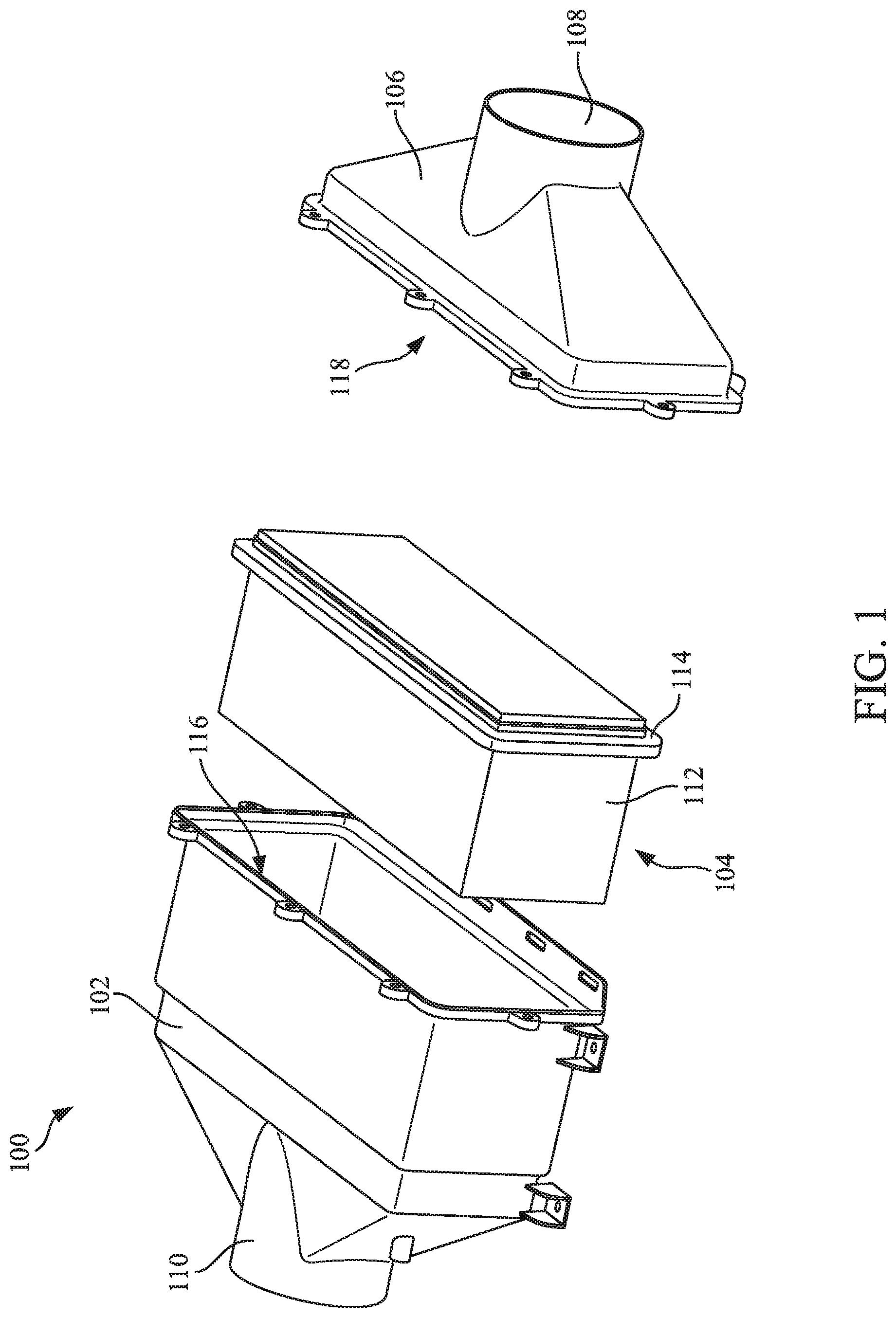
FIG. 1 shows an exploded view of a filtration system according to an example embodiment.
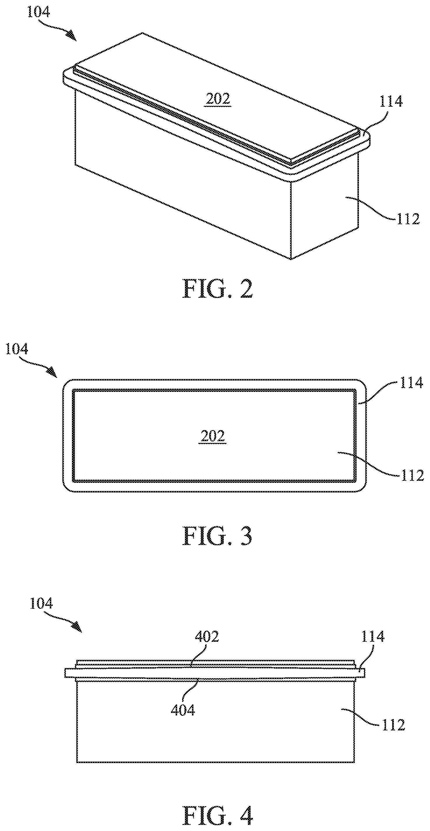
FIG. 2 shows a perspective view of the filter element of the filtration system of FIG. 1.
FIG. 3 shows a top view of the filter element of the filtration system of FIG. 1.
FIG. 4 shows a side view of the filter element of the filtration system of FIG. 1.
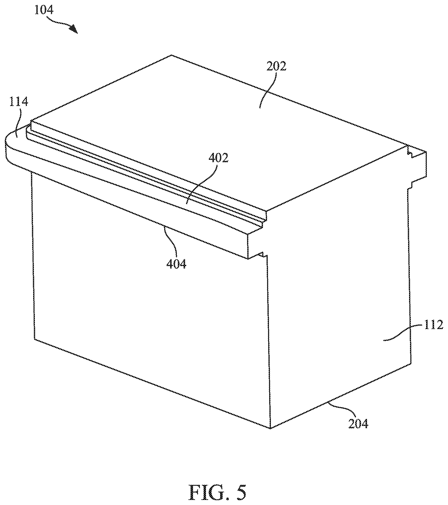
FIG. 5 shows a perspective cross-sectional view of the filter element of the filtration system of FIG. 1.
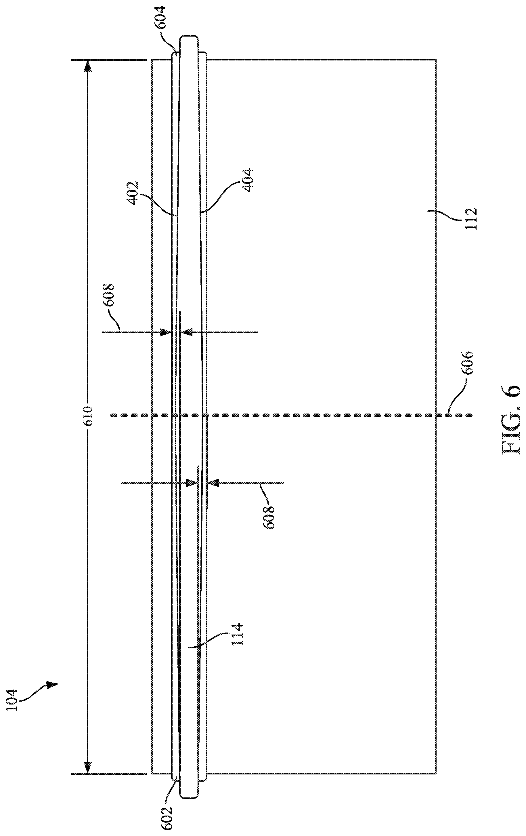
FIG. 6 shows another side view of the filter element of the filtration system of FIG. 1.
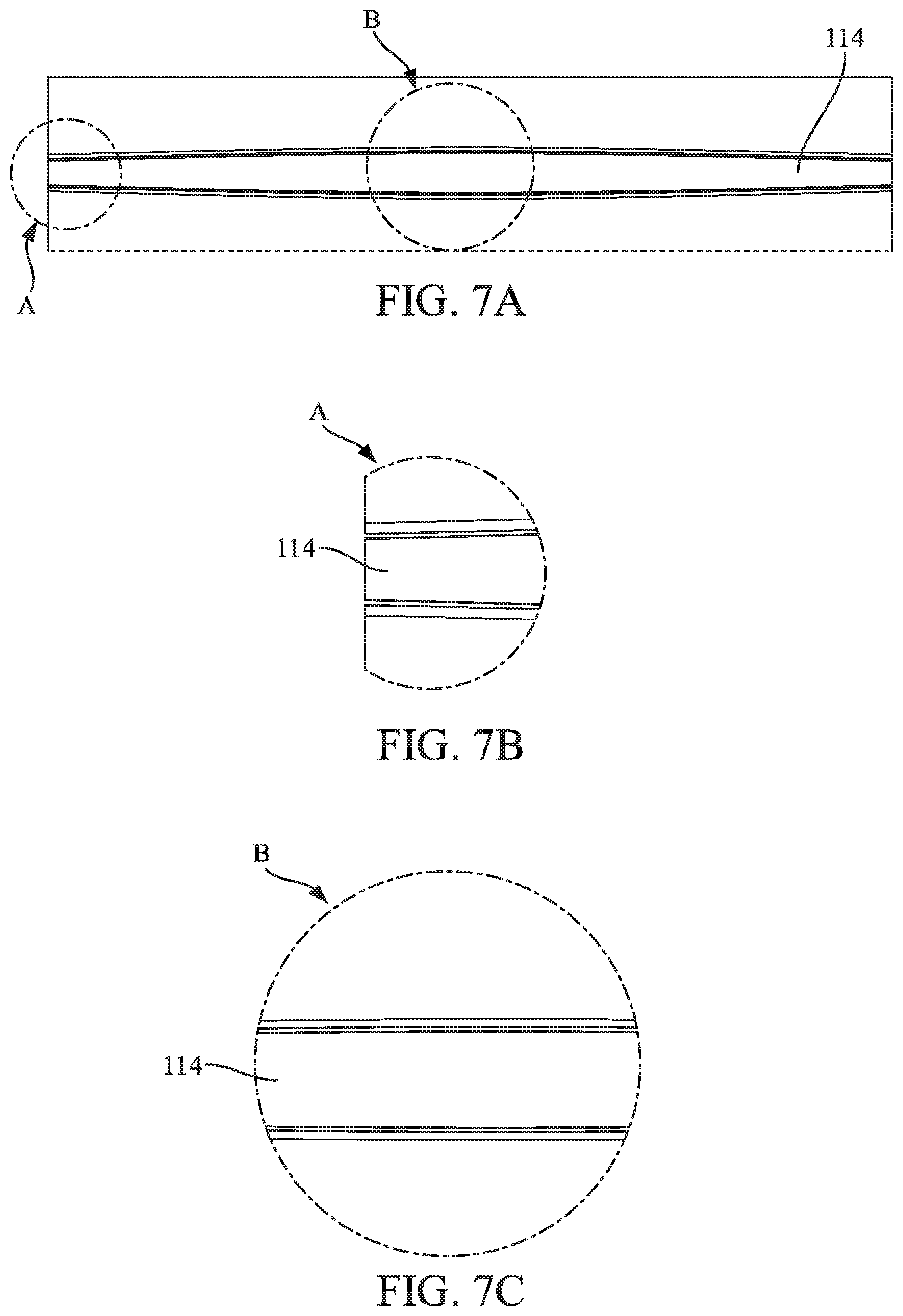
FIGS. 7A through 7C show views of the housing and cover of the filtration system of FIG. 1 forming a seal with the filter element of the filtration system of FIG. 1.
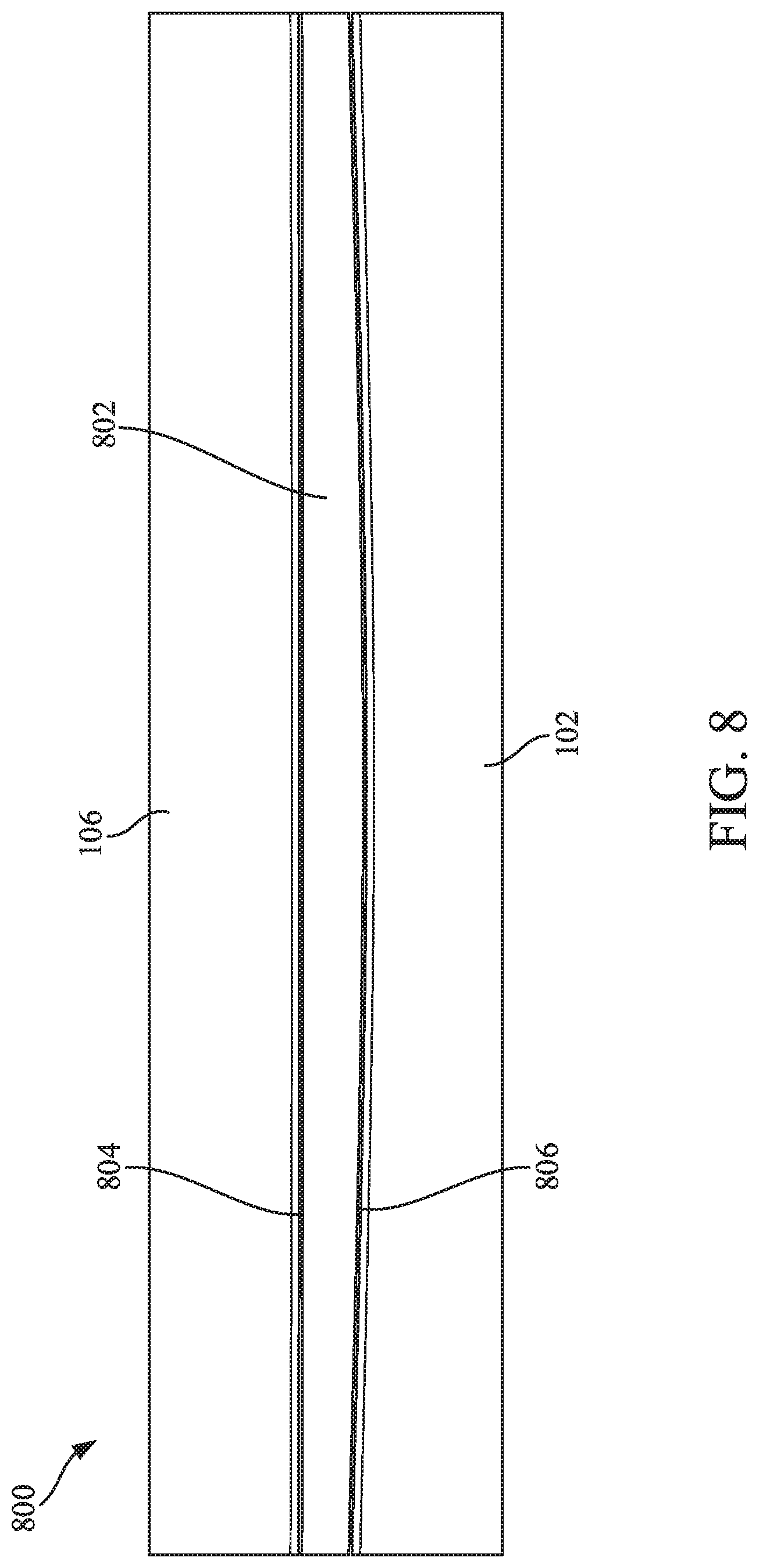
FIG. 8 shows a side view of a filtration system according to an example embodiment.
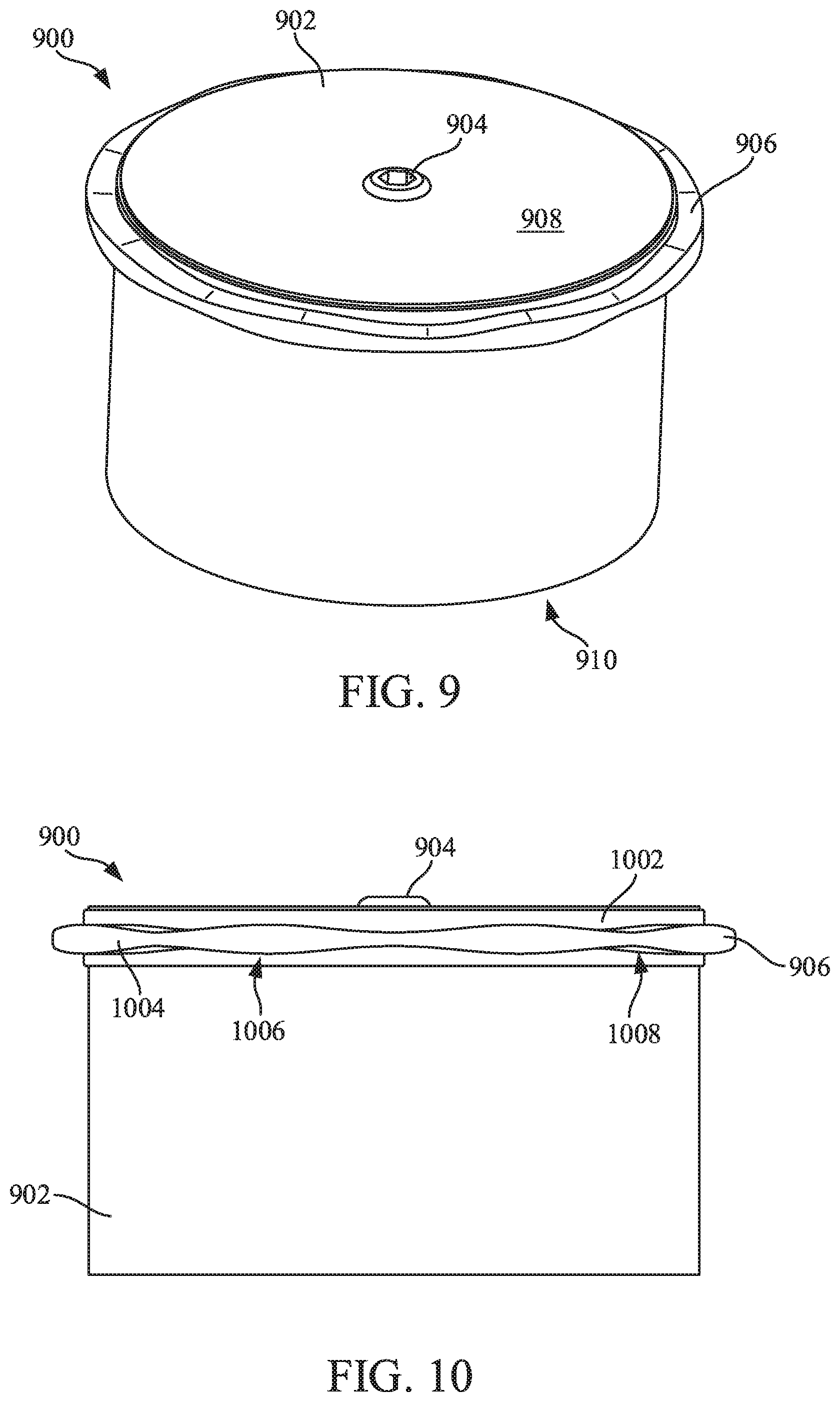
FIG. 9 shows a perspective view of a cylindrical filter element according to an example embodiment.
FIG. 10 shows a side view of the cylindrical filter element of FIG. 9.
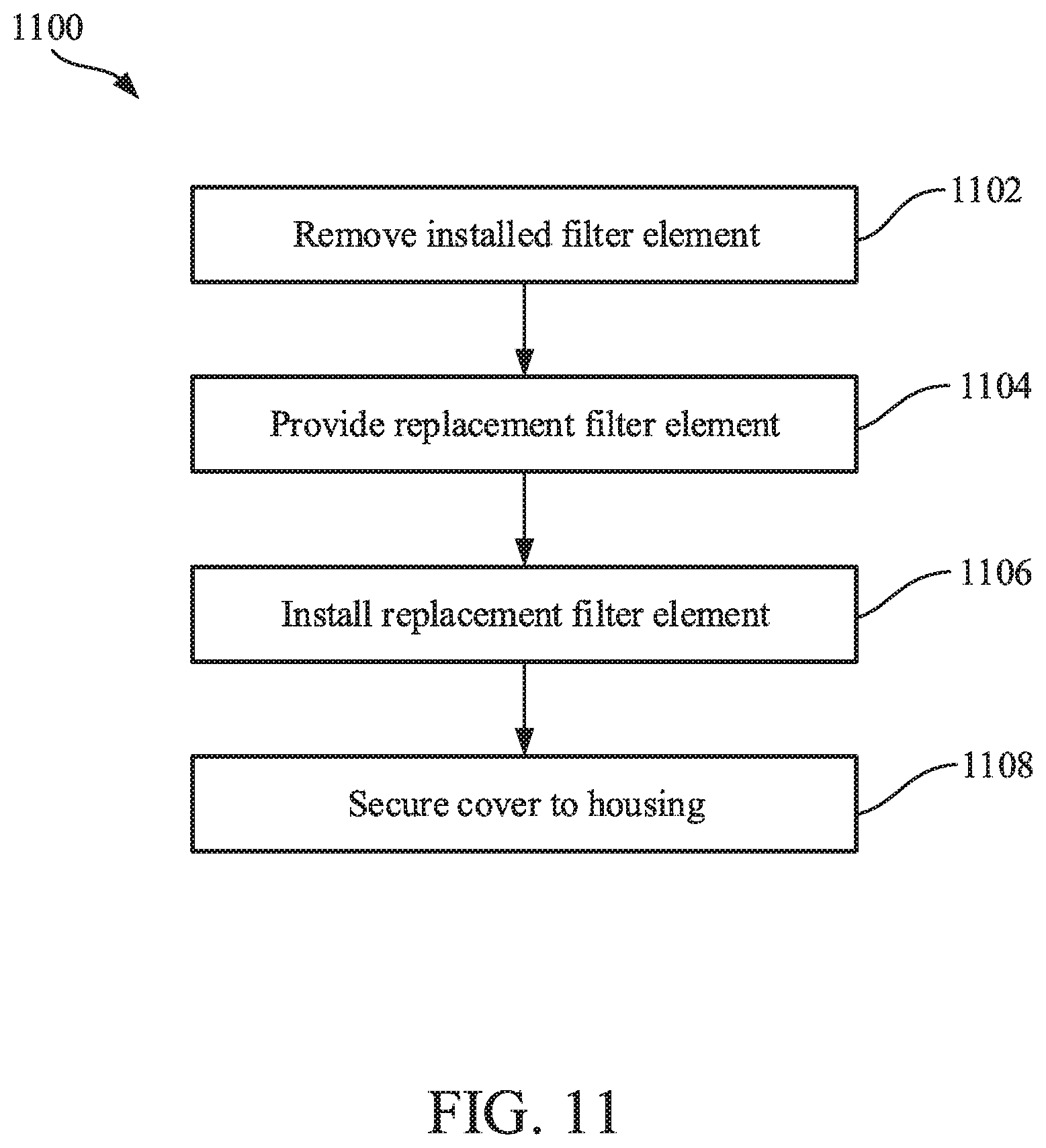
FIG. 11 shows a flow diagram of a method of replacing a filter element in a filtration system according to an example embodiment.
DETAILED DESCRIPTION
Referring to the figures generally, filtration systems having filter elements having an axial seal member with a variable cross-section are described. The variable cross-section is matched by the non-planar sealing surfaces of the housing and housing cover that receive the filter elements. The non-planar sealing surfaces of the housing and the housing cover prevent proper filtration system function when an unauthorized replacement filter element having a flat axial seal member is installed in the housing.
Referring to FIG. 1, an exploded view of a filtration system 100 is shown according to an example embodiment. In some arrangements, the filtration system 100 is an air filtration system. The filtration system 100 includes a housing 102, a filter element 104, and a cover 106. The cover 106 includes an inlet 108. The housing 102 includes an outlet 110. The filter element 104 includes filter media 112 and a seal member 114. The filter media 112 may include any of pleated media, corrugated media, tetrahedral media, or variations thereof. U.S. Pat. No. 8,397,920, entitled "PLEATED FILTER ELEMENT WITH TAPERING BEND LINES," by Moy et al., filed on Oct. 14, 2011, and issued on Mar. 19, 2013, assigned to Cummins Filtration IP Inc., which is incorporated by reference in its entirety and for all purposes, describes a tetrahedral filter media. Some configurations of tetrahedral filter media include a plurality of inlet tetrahedron flow channels and a plurality of outlet tetrahedron flow channels. The inlet tetrahedron merge in a central portion of the filter material, thereby allowing axial cross-flow of air between the inlet tetrahedron channels prior to the air passing through the filter media. Such an arrangement provides for additional dust loading on the upstream side of the media, which increases filter capacity. Specific arrangements of such tetrahedral filter media are further described in U.S. Pat. No. 8,397,920.
Although the filter media 112 is shown in FIG. 1 as a rectangular block having a rectangular cross-sectional shape, the filter media 112 can be arranged in other shapes. For example, the filter media 112 can be arranged as a cylindrical filter block having a circular cross-sectional shape, as a wound filter block (e.g., as described below with respect to FIGS. 9 and 10), as an oval filter block having an oval cross-sectional shape, as a panel, as a race-track shape, or the like.
When the filtration system 100 is in the assembled state, the filter element 104 is positioned within a central compartment of the housing 102. The seal member 114 contacts the housing sealing surface 116. The cover 106 is removably coupled to the housing (e.g., by fasteners). As the cover 106 is secured to the housing, the cover sealing surface 118 contacts the seal member 114 and compresses the seal member 114 between the housing 102 and the cover 106 to form an axial seal. The arrangement of the seal member 114 is described in further detail below with respect to FIGS. 2 through 7C.
Generally, when the filtration system 100 is assembled, the filtration system 100 filters air and provides the filtered air to a device, such as an internal combustion engine. The filtration system 100 receives air to be filtered through the inlet 108. The air passes from the inlet 108, into the cover 106, and through the filter media 112 of the filter element 104. As the air passes through the filter media 112, the filter media 112 removes contaminants (e.g., dirt, dust, moisture, etc.) contained in the air. The filtered air then passes through the housing 102 and out the outlet 110. As the filter element 104 filters the air, the filter media 112 captures the contaminants. Accordingly, the filter element 104 requires periodic replacement as the filter media 114 reaches capacity.
Referring to FIGS. 2 through 6, various views of the filter element 104 are shown. As shown best in the perspective view of the filter element 104 (FIG. 2) and the top view (FIG. 3), the filter media 112 is arranged as a filter block. The filter media 112 includes an inlet face 202 defining a dirty side of the filter element 114 and an outlet face 204 (opposite the inlet face; shown best in FIG. 5) defining a clean side of the filter element 104. The seal member 114 is coupled to and circumscribes at least a portion of an overall longitudinal length (i.e., a perimeter wall) of the filter media 112. The seal member 114 is positioned between the inlet face 202 and the outlet face 204. In some arrangements, the seal member 114 is adjacent to the inlet face 202. As shown in FIG. 3, in some arrangements the seal member 114 is substantially rectangular in shape when viewed from the top perspective. In such arrangements and similar arrangements, the seal member 114 includes two short sides and two long sides.
As shown best in FIGS. 4 through 6, the seal member 114 includes a first sealing surface 402 and a second sealing surface 404. The seal member 114 has a variable cross-section. Accordingly, the distance between the first sealing surface 402 and the second sealing surface 404 varies along at least a portion of the seal member 114. In arrangements where the seal member 114 is substantially rectangular in shape when viewed from the top perspective, the variable cross-section is caused by the arc-shape of the first and second sealing surfaces 402 and 404. In arrangements where the seal member 114 is substantially rectangular in shape, for example, the arc-shaped sealing surfaces 402 and 404 may be only along one of the four sides, only along the two long sides, only along the two short sides, or along one of the long sides and one of the short sides.
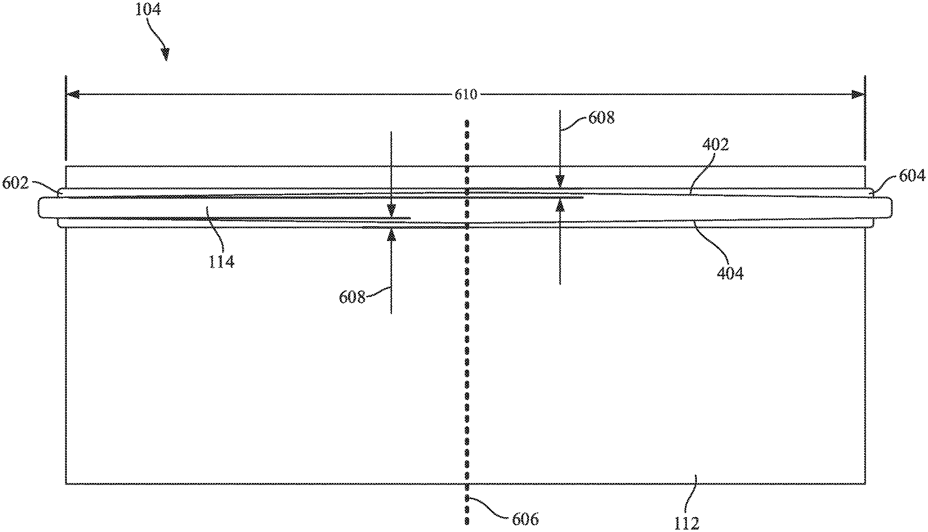
Referring to FIG. 6, the arc-shape of the first and second sealing surfaces 402 and 404 is shown in greater detail. The arc-shaped profile of the first and second sealing surfaces 402 and 404 extends from a first end 602 of the seal member to a second end 604 of the seal member. The arc-shaped profile comprises a continuous curve between the first end 602 and the second end 604. The continuous curve is a convex curve. In some arrangements, the continuous curve of the arc-shaped profile is symmetrical about a center axis 606 of the filter element 104. In such arrangements, the cross-section of the seal member 114 is greatest at the center axis 606 and smallest at the first end 602 and the second end 604. Each of the first and second sealing surfaces 402 is elevated at the center axis 606 by a height 608 with respect to the first and second ends 602 and 604. The height 608 is significantly smaller than a span distance 610 between the first end 602 and the second end 604. In some arrangements, the ratio of the span distance 610 to the height 608 is approximately 100:1. In further arrangements, the ratio of the span distance 610 to the height 608 is 102:1. In additional arrangements, the ratio of the span distance 610 to the height 608 is greater than 10:1. In still further arrangements, the ratio of the span distance 610 to the height 608 is greater than 50:1. The resulting arc formed by the continuous curve is a slight convex arc. The slight convex arc advantageously permits greater compression of the center of the seal member 114 (e.g., in the area of the central axis 606) to compensate for potential flex or warping of the housing sealing surface 116 of the housing 102 and the cover sealing surface 118 of the cover 106. Additionally, the relatively small amplitude maintains a majority of the sealing force in the axial direction thereby creating a strong axial seal.
FIG. 7A shows a side view of the housing 102 and the cover 106 forming a seal with the seal member 114. FIG. 7B shows a close-up view of section A of FIG. 7A. FIG. 7C shows a close-up view of section B of FIG. 7A. As shown in FIGS. 7A through 7C, when the filter element 104 is placed in the housing 102 and secured in place with the cover 106, the housing sealing surface 116 and the cover sealing surface 118 form an axial seal with the seal member 114. The housing sealing surface 116 and the cover sealing surface 118 are non-planar and arced such that the housing sealing surface 116 and the cover sealing surface 118 are complementary with the variable cross-section of the seal member 114. The seal member 114 is compressed between the housing sealing surface 116 and the cover sealing surface 118. In some arrangements, the amount of compression at the center portion 702 of the seal member 114 (as emphasized in area B and shown in FIG. 7C) is 1.0 mm. In such arrangements, the amount of compression of at the first end 602 and the second 604 may be less than 1.0 mm.
If an unauthorized replacement filter element having a flat axial seal member (e.g., an axial seal member that does not include the arc-shaped profile of the seal member 114), the housing 102 and the cover 106 will not form a proper seal against the flat axial seal member. As noted above, the housing sealing surface 116 and the cover sealing surface 118 are non-planar and arced such that the housing sealing surface 116 and the cover sealing surface 118 are complementary with the variable cross-section of the seal member 114. Since the housing sealing surface 116 of the housing 102 and the cover sealing surface 118 of the cover 106 are arced to form a proper seal with the seal member 114 (as discussed above with respect to FIGS. 7A through 7C), a first gap will exist between the housing sealing surface 116 and the flat axial seal member, and a second gap will exist between the cover sealing surface 118 and the flat axial seal member. The first and second gaps would provide bypass flow paths around the unauthorized replacement filter element thereby drastically reducing the efficiency of the filtration system 100.
Referring to FIG. 8, a close-up side view of a filtration system 800 is shown according to an example embodiment. The filtration system 800 is substantially similar to the filtration system 100. Accordingly, like numbering is used to designate similar components. The primary difference between the filtration system 800 and the filtration system 100 is that the seal member 802 of the filtration system 800 has a different cross-section than the seal member 114 of the filtration system 100. The seal member 802 includes a first sealing surface 804 and a second sealing surface 806. Similar to the seal member 114, the seal member 802 has a variable cross-section. Accordingly, the distance between the first sealing surface 804 and the second sealing surface 806 varies along at least a portion of the seal member 802. Unlike the seal member 114, only one of the first sealing surface 804 and the second sealing surface 806 is non-planar and has an arc-shaped profile caused by a continuous convex curve between the first and second ends of the seal member 802 (e.g., as described above with respect to the arc-shaped profile of the seal member 114), while the other of the first sealing surface 804 and the second sealing surface 806 is flat or planar. As shown in FIG. 8, the first sealing surface 804 is flat, and the second sealing surface 806 is arced in a similar manner as described above with respect to either the first or second sealing surfaces 402 or 404 of the seal member 114. Accordingly, the cover sealing surface 118 of the cover 106 is flat to form a proper seal with the first sealing surface 804.
Referring to FIGS. 9 and 10, views of a filter element 900 are shown according to an example embodiment. The filter element 900 is a cylindrical filter element having filter media 902 surrounding a central core 904. The filter media 902 may include any of pleated media, corrugated media, tetrahedral media, or variations thereof. In some arrangements, the filter media 902 is wound around the core 904. The filter element 900 includes a seal member 906. When the filter element 900 is positioned in a filtration system housing, the seal member 906 is compressed between the housing and a housing cover (e.g., in a similar manner as described above with respect to the filter element 104 of the filtration system 100). The filter media 902 includes an inlet face 908 and an outlet face 910. When the filter element 900 is installed within the housing and the filtration system is activated, air to be filtered passes through the filter media 902 from the inlet face 908 and out of the outlet face 910.
The seal member 906 is coupled to and circumscribes an axial wall of the filter media 902. The seal member 906 is positioned between the inlet face 908 and the outlet face 910. In some arrangements, the seal member 906 is adjacent to the inlet face 908. The seal member 906 is substantially ring-shaped when viewed from the top perspective. As shown best in FIG. 10, the seal member 906 includes a first sealing surface 1002 and a second sealing surface 1004. The seal member 906 does not have a uniform cross-section. Accordingly, the distance between the first sealing surface 1002 and the second sealing surface 1004 varies along at least a portion of the circumference of the seal member 906. Each of the first sealing surface 1002 and the second sealing surface 1004 are non-planar. Both the first sealing surface 1002 and the second sealing surface 1004 have a continuous wave profile (as shown in FIG. 10). In the arrangement of FIG. 10, the continuous wave profiles of the first sealing surface 1002 and the second sealing surface 1004 are aligned such that the seal member 906 has thick portions 1006 and thin portions 1008. In other arrangements, the continuous wave profiles of the first and second sealing surfaces 1002 and 1004 are offset such that the seal member 906 has a substantially uniform thickness around the circumference.
In some arrangements, the continuous wave profile is a sinusoidal wave pattern. The amplitude distance of the sinusoidal wave pattern is substantially smaller than the period distance (i.e., the distance between successive peaks in the sinusoidal wave pattern). In some arrangements, the ratio of the period distance to the amplitude distance is approximately 100:1. In further arrangements, the ratio of the period distance to the amplitude distance is 102:1. In additional arrangements, the ratio of the period distance to the amplitude distance is greater than 10:1. In still further arrangements, the ratio of the period distance to the amplitude distance is greater than 50:1. The sinusoidal wave pattern is a wave pattern having a relatively small amplitude. The relatively small amplitude advantageously permits greater compression of the of the seal member 906 at the peak portions 1006 to compensate for potential flex or warping of the housing sealing surface of the housing and the cover sealing surface of the cover. Additionally, the relatively small amplitude maintains a majority of the sealing force in the axial direction thereby creating a strong axial seal.
In order for the filter element 900 to form a proper seal with the housing and the housing cover, the sealing surfaces of the housing and the housing cover have a matching sinusoidal wave pattern. If an unauthorized replacement filter element having a flat axial seal member (e.g., an axial seal member that does not include the arc-shaped profile of the seal member 114), the housing and the cover will not form a proper seal against the flat axial seal member. Since the housing sealing surface of the housing and the cover sealing surface of the cover have waved sealing surfaces to form a proper axial seal with the seal member 906, gaps will exist between the housing sealing surface, the cover sealing surface, and the flat axial seal member. The gaps would provide bypass flow paths around the unauthorized replacement filter element thereby drastically reducing the efficiency of the filtration system.
Referring to FIG. 11, a flow diagram of a method 1100 of replacing a filter element in a filtration system (e.g., filtration system 100) is shown according to an example embodiment. The method 1100 begins when a filter element is removed from the filtration system at 1102. The filter element is removed by a technician or another individual servicing the filtration system. To remove the filter cartridge, a filtration system cover (e.g., cover 106) is removed from the housing (e.g., housing 102) to provide access to the installed filter cartridge. After the filter cartridge is removed at 1102, a replacement filter cartridge (e.g., filter element 104) is provided at 1104. The filter element 104 includes filter media and an axial seal member (e.g., seal member 114) of the type discussed above. The axial seal member includes at least one sealing surface having an arc-shaped profile comprising a continuous curve between a first and second end of the seal member. The arc-shaped profile of the axial seal member substantially matches a mating arc-shaped profile in the cover and/or housing sealing surfaces.
The replacement filter element is installed at 1106. The replacement filter element is inserted into the housing. When the replacement filter element is inserted into the housing a first sealing surface of the axial seal member contacts a housing sealing surface. The replacement filter element may be of the type discussed above with regard to the filter media and the axial seal member. The cover is secured to the housing at 1108. When the cover is secured to the housing, a second sealing surface of the axial seal member contacts a cover sealing surface of the cover. The cover may be secured to the housing via a clamp, a fastener, a snap-fit connection, or the like. As the cover is secured to the housing, the seal member is compressed between the housing sealing surface and the cover sealing surface, forming an axial seal.
It should be noted that any use of the term "example" herein to describe various embodiments is intended to indicate that such embodiments are possible examples, representations, and/or illustrations of possible embodiments (and such term is not intended to connote that such embodiments are necessarily extraordinary or superlative examples).
The terms "coupled" and the like as used herein mean the joining of two members directly or indirectly to one another. Such joining may be stationary (e.g., permanent) or moveable (e.g., removable or releasable). Such joining may be achieved with the two members or the two members and any additional intermediate members being integrally formed as a single unitary body with one another or with the two members or the two members and any additional intermediate members being attached to one another.
References herein to the positions of elements (e.g., "top," "bottom," "above," "below," etc.) are merely used to describe the orientation of various elements in the FIGURES. It should be noted that the orientation of various elements may differ according to other example embodiments, and that such variations are intended to be encompassed by the present disclosure.
The term "approximately" when used with respect to values means plus or minus five percent of the associated value.
It is important to note that the construction and arrangement of the various example embodiments are illustrative only. Although only a few embodiments have been described in detail in this disclosure, those skilled in the art who review this disclosure will readily appreciate that many modifications are possible (e.g., variations in sizes, dimensions, structures, shapes and proportions of the various elements, values of parameters, mounting arrangements, use of materials, colors, orientations, etc.) without materially departing from the novel teachings and advantages of the subject matter described herein. For example, elements shown as integrally formed may be constructed of multiple parts or elements, the position of elements may be reversed or otherwise varied, and the nature or number of discrete elements or positions may be altered or varied. The order or sequence of any process or method steps may be varied or re-sequenced according to alternative embodiments. Additionally, features from particular embodiments may be combined with features from other embodiments as would be understood by one of ordinary skill in the art. Other substitutions, modifications, changes and omissions may also be made in the design, operating conditions and arrangement of the various example embodiments without departing from the scope of the present invention.
* * * * *
References
D00000
D00001
D00002
D00003
D00004
D00005
D00006
D00007
D00008
XML
uspto.report is an independent third-party trademark research tool that is not affiliated, endorsed, or sponsored by the United States Patent and Trademark Office (USPTO) or any other governmental organization. The information provided by uspto.report is based on publicly available data at the time of writing and is intended for informational purposes only.
While we strive to provide accurate and up-to-date information, we do not guarantee the accuracy, completeness, reliability, or suitability of the information displayed on this site. The use of this site is at your own risk. Any reliance you place on such information is therefore strictly at your own risk.
All official trademark data, including owner information, should be verified by visiting the official USPTO website at www.uspto.gov. This site is not intended to replace professional legal advice and should not be used as a substitute for consulting with a legal professional who is knowledgeable about trademark law.