Method of generating hydro electric energy in rivers and streams without dams and/or locks
Vannan, Jr. , et al. May 25, 2
U.S. patent number 11,018,554 [Application Number 15/330,417] was granted by the patent office on 2021-05-25 for method of generating hydro electric energy in rivers and streams without dams and/or locks. The grantee listed for this patent is John Brian Dahl, Frederick Forbes Vannan, Jr.. Invention is credited to John Brian Dahl, Frederick Forbes Vannan, Jr..


| United States Patent | 11,018,554 |
| Vannan, Jr. , et al. | May 25, 2021 |
Method of generating hydro electric energy in rivers and streams without dams and/or locks
Abstract
A method of generating hydro-electric energy utilizing a conduit located beneath the surface of a river or stream to feed water into a hydro-electric turbine, eliminating the need to build costly and time-consuming dams and locks.
| Inventors: | Vannan, Jr.; Frederick Forbes (Clinton, OH), Dahl; John Brian (Vienna, WV) | ||||||||||
|---|---|---|---|---|---|---|---|---|---|---|---|
| Applicant: |
|
||||||||||
| Family ID: | 1000005577135 | ||||||||||
| Appl. No.: | 15/330,417 | ||||||||||
| Filed: | September 19, 2016 |
Prior Publication Data
| Document Identifier | Publication Date | |
|---|---|---|
| US 20180083508 A1 | Mar 22, 2018 | |
| Current U.S. Class: | 1/1 |
| Current CPC Class: | H02K 7/1823 (20130101); F03B 13/08 (20130101); F03B 13/10 (20130101); Y02E 10/20 (20130101); F05B 2240/13 (20130101) |
| Current International Class: | H02K 7/18 (20060101); F03B 13/10 (20060101); F03B 13/08 (20060101) |
| Field of Search: | ;290/42,43,52,53,54 |
References Cited [Referenced By]
U.S. Patent Documents
| 4078871 | March 1978 | Perkins, Jr. |
| 4143990 | March 1979 | Atencio |
| 4494567 | January 1985 | Troyen |
| 4782663 | November 1988 | Bellamy |
| 4804855 | February 1989 | Obermeyer |
| 5105094 | April 1992 | Parker |
| 5754446 | May 1998 | Fisher, Jr. |
| 2009/0152871 | June 2009 | Ching |
| 2010/0135766 | June 2010 | Allaei |
| 2011/0006531 | January 2011 | Ghouse |
| 2011/0109089 | May 2011 | Frye |
| 2011/0260460 | October 2011 | Rovinsky |
| 2012/0146330 | June 2012 | Shifrin |
| 2014/0312624 | October 2014 | da Silva |
| 2015/0014995 | January 2015 | Nishioka |
| 2015/0167626 | June 2015 | Roberts |
| 2015/0198138 | July 2015 | Hanna |
| 2016/0208766 | July 2016 | Fei |
| 2016/0290310 | October 2016 | Bhende |
| 2016/0298596 | October 2016 | Pereira De Gouveia Lopes De Almeida |
| 2017/0145981 | May 2017 | Culpepper |
| WO 2015072869 | May 2015 | WO | |||
Claims
The invention claimed is:
1. A hydro-electric generation system for use in rivers which is comprised of a conduit having an inlet end and a downstream end and a hydro-electric turbine which is situated at the downstream end of the conduit through an exit attachment, wherein the conduit is positioned in the direction of water flow with the inlet end of the conduit being upstream and at a higher elevation in the river than the downstream end of the conduit, wherein the inlet and of the conduit is positioned in the river at a point where the river has a higher surface level than does the river at the downstream end of the conduit.
2. The hydro-electric generation system of claim 1 wherein a semi-circular coffer dam is situated at the inlet end of the conduit to utilize river flow rate to increase river water surface elevation at the inlet and of the conduit and thereby increase head pressure at the hydro-electric turbine.
3. The hydro-electric generation system of claim 1 wherein the conduit is made from two flat sheets of material seamed along its length on both sides.
4. The hydro-electric generation system of claim 1 wherein the conduit has multiple inlets feeding multiple hydro-electric turbines.
5. The hydro-electric generation system of claim 1 wherein the conduit is attached to a river bottom or a river shoreline of the river.
6. The hydro-electric generation system of claim 1 which is further comprised of a means for adjusting the elevation of the inlet end of the conduit to maximize turbine head pressure at various river levels.
7. The hydro-electric generation system of claim 6 wherein the elevation of the inlet end of the conduit is controlled by floatation.
8. The hydro-electric generation system of claim 6 which is further comprised of a mechanical mechanism for adjusting the elevation of the inlet end of the conduit.
9. The hydro-electric generation system of claim 1 wherein the hydro-electric turbine is positioned to be above the downstream river water surface elevation and below the elevation of the conduit inlet.
10. A method for producing electric power which comprises generating electricity with the hydro-electric generation system as specified in claim 1.
11. A method for generating hydro-electric energy which comprises creating a pressure head to power the hydro-electric turbine in the hydro-electric generation system specified in claim 1 from the natural downward flow of water in the river.
12. The method for generating hydro-electric energy of claim 11 wherein the pressure head is increased by adjusting the elevation of the inlet end of the conduit.
13. A method for generating hydro-electric energy which comprises allowing the water flow of the river to flow through the conduit of the hydro-electric generation system as specified in claim 1 to create a pressure head to power the hydro-electric turbine.
14. The hydra-electric generation system of claim 1 wherein the conduit has multiple exits feeding multiple hydro-electric turbines.
15. The method of claim 1 wherein the conduit is comprised of plastic.
16. The method of claim 1 wherein the conduit is comprised of metal.
Description
Most large hydro-electric energy generation facilities utilize large expensive dams which flood sometimes useful land forming a lake or hamper river navigation requiring expensive lock systems.
The most suitable natural falls and dam locations on rivers in the world are already being utilized to generate hydro-electric energy. Some existing dams on rivers are being utilized to generate hydro-electric energy where cost vs benefits analysis can justify the project.
There are many rivers and streams in the world which have a flow rate and elevation drop suitable for hydro-electric generation, but are not suitable for dams Because they would hamper river transportation or flood valuable land.
SUMMARY OF INVENTION
This invention provides a novel method for generating hydro-electric power on rivers and streams without requiring the building of expensive and time consuming dams and locks and without hindering river transportation or the environment.
The method of this invention utilizes a conduit located at least partially beneath the surface of a river or stream to feed water into a hydro-electric turbine. The conduit is positioned in the direction of river water flow with the inlet end of the conduit upstream and at a higher elevation than the downstream end of the conduit which feeds water into a hydro-electric turbine.
The upstream water inlet end of the conduit can be positioned to be near the river water surface and the downstream end of the conduit is attached to the hydro-electric turbine which is below the water surface.
A semi-circular coffer dam can be used at the inlet end of the conduit to utilize river flow rate to increase river water surface elevation at the inlet end of the conduit and thereby increase the head pressure at the hydro-electric turbine.
The conduit of this invention can have any cross-sectional shape including the following shapes: circular, oval, rectangular and square and it can be made of any material including plastic and metal.
The conduit of this invention can be seamless or seamed in any direction including seams parallel and/or perpendicular to the direction of water flow inside the conduit.
The conduit of this invention can be made from two or more flat sheets of material seamed along both sides parallel to the water flow inside the conduit.
The conduit of this invention can have multiple inlets and/or multiple exits feeding multiple hydro-electric turbines.
The conduit of this invention can be attached to the bottom or shore line of a river or stream.
The elevation of the inlet end of the conduit can be mechanically adjusted to maximize turbine head pressure at various river levels. The elevation of the inlet end of the conduit can also be controlled by floatation.
The hydro-electric turbine of this invention can be positioned to be above the downstream river water surface elevation and below the conduit inlet elevation.
DESCRIPTION OF DRAWINGS (DRAWINGS NOT TO SCALE)
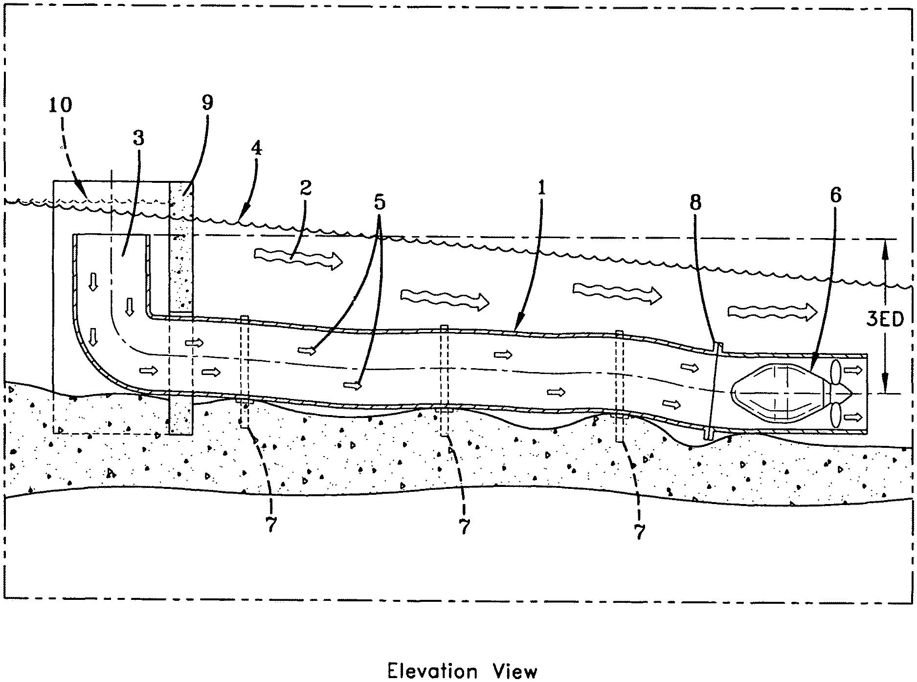
FIG. 1 shows an elevation view of the conduit (1) fully submerged in a river flowing from left to right (2). The conduit inlet (3) is below the river surface (4) to allow gravity to fill the conduit. The water flows (5) through the conduit from the inlet (3) to the hydro-turbine (6) because the conduit inlet is at a higher elevation than the hydro-turbine. The elevation drop (3ED) from the conduit inlet to the hydro-turbine provides the head pressure required to drive the hydro-turbine which produces electric power. FIG. 1 also shows the conduit attached to the river bottom with straps (7) and to the hydro-turbine connection (8).
FIG. 2 shows a plan view of two identical conduit/turbine systems with one system on each side (11A and 11B) of a river. Each conduit/turbine system has one conduit inlet (3) and one connection (8) to one hydro-turbine (6).
A semi-circular coffer dam (9) is shown around the conduit inlet (3) in FIG. 1 and each inlet (3) in FIG. 2. The coffer dams utilize river flow (2) to increase river surface elevation (10) at the conduit inlets and thereby increase head pressure at the hydro-turbine.
FIG. 3 shows a plan view of a conduit/turbine system with two conduit inlets (3) and four conduit exits each feeding one of four hydro-turbines (6).
FIG. 4A and FIG. 46 show elevation views of a single conduit/turbine system wherein the elevation of the inlet end (3) of the conduit (1) is vertically adjustable using a mechanical mechanization (12) or a floatation mechanization (13) to maximize head pressure at various river levels. FIG. 4A shows the river surface at low elevations (14) and depths (D1) during dry seasons and FIG. 46 shows the river surface at higher elevations (15) and depths (D2) during wet seasons.
FIG. 5 shows a cross-sectional view of a conduit made from two flat sheets of any suitable material seamed along its length on both sides (17A) parallel to water flow (5) inside the conduit. The broken parallel lines show the two flat sheets (16A) of the conduit seamed at the edges (17A) but without water inside the conduit. The solid lines show the same seamed conduit (166) and seams (17B) with water flowing inside the conduit (5) and causing the cross-sections shape to be oval or circular.
* * * * *
D00000
D00001
D00002
D00003
D00004
D00005
D00006
XML
uspto.report is an independent third-party trademark research tool that is not affiliated, endorsed, or sponsored by the United States Patent and Trademark Office (USPTO) or any other governmental organization. The information provided by uspto.report is based on publicly available data at the time of writing and is intended for informational purposes only.
While we strive to provide accurate and up-to-date information, we do not guarantee the accuracy, completeness, reliability, or suitability of the information displayed on this site. The use of this site is at your own risk. Any reliance you place on such information is therefore strictly at your own risk.
All official trademark data, including owner information, should be verified by visiting the official USPTO website at www.uspto.gov. This site is not intended to replace professional legal advice and should not be used as a substitute for consulting with a legal professional who is knowledgeable about trademark law.