Roller ball assembly with superhard elements
Miess , et al. May 25, 2
U.S. patent number 11,014,759 [Application Number 16/049,631] was granted by the patent office on 2021-05-25 for roller ball assembly with superhard elements. This patent grant is currently assigned to XR Downhole, LLC. The grantee listed for this patent is William W. King, David P. Miess, Gregory Prevost, Michael R. Reese, Michael Williams. Invention is credited to William W. King, David P. Miess, Gregory Prevost, Michael R. Reese, Michael Williams.


| United States Patent | 11,014,759 |
| Miess , et al. | May 25, 2021 |
Roller ball assembly with superhard elements
Abstract
A roller ball assembly is provided. The assembly includes a primary roller ball supported by a support element that is composed of a superhard material. The assembly includes a cup defining a cavity within which the support element is positioned. A cap is coupled with the cup and positioned to retain the primary roller ball within the cavity. Also, a cup is disclosed for supporting roller balls. Additionally, disclosed are system and apparatus incorporating the assembly, as well as to methods of making and using the same.
| Inventors: | Miess; David P. (Spring, TX), Prevost; Gregory (Spring, TX), Williams; Michael (Houston, TX), King; William W. (Houston, TX), Reese; Michael R. (Houston, TX) | ||||||||||
|---|---|---|---|---|---|---|---|---|---|---|---|
| Applicant: |
|
||||||||||
| Assignee: | XR Downhole, LLC (Houston,
TX) |
||||||||||
| Family ID: | 1000005573709 | ||||||||||
| Appl. No.: | 16/049,631 | ||||||||||
| Filed: | July 30, 2018 |
Prior Publication Data
| Document Identifier | Publication Date | |
|---|---|---|
| US 20200031586 A1 | Jan 30, 2020 | |
| Current U.S. Class: | 1/1 |
| Current CPC Class: | F16C 29/046 (20130101); B65G 39/025 (20130101); F16C 2206/82 (20130101); F16C 2206/60 (20130101); F16C 2202/04 (20130101); F16C 2206/56 (20130101) |
| Current International Class: | B65G 39/02 (20060101); F16C 29/04 (20060101) |
References Cited [Referenced By]
U.S. Patent Documents
| 1798604 | March 1931 | Hoke |
| 1963956 | June 1934 | James |
| 2259023 | October 1941 | Clark |
| 2299978 | October 1942 | Hall |
| 2407586 | September 1946 | Summers |
| 2567735 | September 1951 | Scott |
| 2693396 | November 1954 | Gondek |
| 2758181 | August 1956 | Crouch |
| 2788677 | April 1957 | Hayek |
| 2877662 | March 1959 | Eduard |
| 2897016 | July 1959 | Baker |
| 2947609 | August 1960 | Strong |
| 2947610 | August 1960 | Hall et al. |
| 3559802 | February 1971 | Eidus |
| 3582161 | June 1971 | Hudson |
| 3603652 | September 1971 | Youden |
| 3650714 | March 1972 | Farkas |
| 3697141 | October 1972 | Garrett |
| 3707107 | December 1972 | Bieri |
| 3741252 | June 1973 | Williams |
| 3745623 | July 1973 | Wentorf et al. |
| 3752541 | August 1973 | Mcvey |
| 3866987 | February 1975 | Garner |
| 3869947 | March 1975 | Vandenkieboom |
| 3920290 | November 1975 | Varts |
| 4085634 | April 1978 | Sattler |
| 4182537 | January 1980 | Oster |
| 4225322 | September 1980 | Knemeyer |
| 4238137 | December 1980 | Furchak et al. |
| 4285550 | August 1981 | Blackburn |
| 4364136 | December 1982 | Hattan |
| 4398772 | August 1983 | Odell |
| 4410054 | October 1983 | Nagel et al. |
| 4410284 | October 1983 | Herrick |
| 4428627 | January 1984 | Teramachi |
| 4432682 | February 1984 | McKewan |
| 4468138 | August 1984 | Nagel |
| 4554208 | November 1985 | MacIver et al. |
| 4560014 | December 1985 | Geczy |
| 4620601 | November 1986 | Nagel |
| RE32380 | March 1987 | Wentorf, Jr. et al. |
| 4662348 | May 1987 | Hall et al. |
| 4679639 | July 1987 | Barr et al. |
| 4689847 | September 1987 | Huber |
| 4720199 | January 1988 | Geczy et al. |
| 4729440 | March 1988 | Hall |
| 4732490 | March 1988 | Masciarelli |
| 4764036 | August 1988 | McPherson |
| 4796670 | January 1989 | Russell et al. |
| 4797011 | January 1989 | Saeki et al. |
| 4858688 | August 1989 | Edwards et al. |
| 4906528 | March 1990 | Cerceau et al. |
| 4958692 | September 1990 | Anderson |
| 5011514 | April 1991 | Cho et al. |
| 5011515 | April 1991 | Frushour |
| 5030276 | July 1991 | Sung et al. |
| 5037212 | August 1991 | Justman et al. |
| 5066145 | November 1991 | Sibley et al. |
| 5067826 | November 1991 | Lemelson |
| 5092687 | March 1992 | Hall |
| 5112146 | May 1992 | Stangeland |
| 5123772 | June 1992 | Anderson |
| 5151107 | September 1992 | Cho et al. |
| 5176483 | January 1993 | Baumann et al. |
| 5193363 | March 1993 | Petty |
| 5205188 | April 1993 | Repenning et al. |
| 5253939 | October 1993 | Hall |
| 5271749 | December 1993 | Rai et al. |
| 5351770 | October 1994 | Cawthorne et al. |
| 5358041 | October 1994 | O'Hair |
| 5358337 | October 1994 | Codatto |
| 5375679 | December 1994 | Biehl |
| 5385715 | January 1995 | Fish |
| 5447208 | September 1995 | Lund et al. |
| 5462362 | October 1995 | Yuhta et al. |
| 5464086 | November 1995 | Coelln |
| 5522467 | June 1996 | Stevens et al. |
| 5533604 | July 1996 | Brierton |
| 5538346 | July 1996 | Frias et al. |
| 5540314 | July 1996 | Coelln |
| 5560716 | October 1996 | Tank et al. |
| 5618114 | April 1997 | Katahira |
| 5645617 | July 1997 | Frushour |
| 5653300 | August 1997 | Lund et al. |
| 5715898 | February 1998 | Anderson |
| 5833019 | November 1998 | Gynz-Rekowski |
| 5855996 | January 1999 | Corrigan et al. |
| 5948541 | September 1999 | Inspektor |
| 6109790 | August 2000 | Gynz-Rekowski et al. |
| 6120185 | September 2000 | Masciarelli, Jr. |
| 6129195 | October 2000 | Matheny |
| 6152223 | November 2000 | Abdo et al. |
| 6164109 | December 2000 | Bartosch |
| 6279716 | August 2001 | Kayatani et al. |
| 6378633 | April 2002 | Moore et al. |
| 6409388 | June 2002 | Lin |
| 6457865 | October 2002 | Masciarelli, Jr. |
| 6488103 | December 2002 | Dennis et al. |
| 6488715 | December 2002 | Pope et al. |
| 6516934 | February 2003 | Masciarelli, Jr. |
| 6652201 | November 2003 | Kunimori et al. |
| 6655845 | December 2003 | Pope |
| 6737377 | May 2004 | Sumiya et al. |
| 6764219 | July 2004 | Doll |
| 6808019 | October 2004 | Mabry |
| 6814775 | November 2004 | Scurlock et al. |
| 6951578 | October 2005 | Belnap et al. |
| 7007787 | March 2006 | Pallini et al. |
| 7198043 | April 2007 | Zhang |
| 7441610 | October 2008 | Belnap et al. |
| 7475744 | January 2009 | Pope |
| 7552782 | June 2009 | Sexton et al. |
| 7703982 | April 2010 | Cooley |
| 7737377 | June 2010 | Dodal et al. |
| 7845436 | December 2010 | Cooley et al. |
| 7861805 | January 2011 | Dick et al. |
| 8069933 | December 2011 | Sexton et al. |
| 8109247 | February 2012 | Wakade et al. |
| 8119240 | February 2012 | Cooper |
| 8163232 | April 2012 | Fang et al. |
| 8277722 | October 2012 | DiGiovanni |
| 8365846 | February 2013 | Dourfaye et al. |
| 8485284 | July 2013 | Sithebe |
| 8613554 | December 2013 | Tessier et al. |
| 8627904 | January 2014 | Voronin |
| 8678657 | March 2014 | Knuteson et al. |
| 8701797 | April 2014 | Baudoin |
| 8734550 | May 2014 | Sani |
| 8757299 | June 2014 | DiGiovanni et al. |
| 8763727 | July 2014 | Cooley et al. |
| 8764295 | July 2014 | Dadson et al. |
| 8881849 | November 2014 | Shen et al. |
| 8939652 | January 2015 | Peterson et al. |
| 8974559 | March 2015 | Frushour |
| 9004198 | April 2015 | Kulkarni |
| 9010418 | April 2015 | Pereyra et al. |
| 9045941 | June 2015 | Chustz |
| 9103172 | August 2015 | Bertagnolli et al. |
| 9127713 | September 2015 | Lu |
| 9145743 | September 2015 | Shen et al. |
| 9222515 | December 2015 | Chang |
| 9273381 | March 2016 | Qian et al. |
| 9366085 | June 2016 | Panahi |
| 9404310 | August 2016 | Sani et al. |
| 9410573 | August 2016 | Lu |
| 9429188 | August 2016 | Peterson et al. |
| 9488221 | November 2016 | Gonzalez |
| 9562562 | February 2017 | Peterson |
| 9643293 | May 2017 | Miess et al. |
| 9702401 | July 2017 | Gonzalez |
| 9732791 | August 2017 | Gonzalez |
| 9776917 | October 2017 | Tessitore et al. |
| 9790749 | October 2017 | Chen |
| 9790818 | October 2017 | Berruet et al. |
| 9803432 | October 2017 | Wood et al. |
| 9822523 | November 2017 | Miess |
| 9840875 | December 2017 | Harvey et al. |
| 9869135 | January 2018 | Martin |
| 10113362 | October 2018 | Ritchie et al. |
| 10294986 | May 2019 | Gonzalez |
| 10307891 | June 2019 | Daniels et al. |
| 10408086 | September 2019 | Meier |
| 10465775 | November 2019 | Miess et al. |
| 10683895 | June 2020 | Hall et al. |
| 10738821 | August 2020 | Miess et al. |
| 10807913 | October 2020 | Hawks et al. |
| 2002/0020526 | February 2002 | Male et al. |
| 2003/0019106 | January 2003 | Pope et al. |
| 2003/0159834 | August 2003 | Kirk et al. |
| 2004/0031625 | February 2004 | Lin et al. |
| 2004/0219362 | November 2004 | Wort et al. |
| 2004/0223676 | November 2004 | Pope et al. |
| 2006/0060392 | March 2006 | Eyre |
| 2006/0165973 | July 2006 | Dumm et al. |
| 2007/0046119 | March 2007 | Cooley |
| 2008/0217063 | September 2008 | Moore et al. |
| 2008/0253706 | October 2008 | Bischof et al. |
| 2009/0020046 | January 2009 | Marcelli |
| 2009/0087563 | April 2009 | Voegele et al. |
| 2010/0037864 | February 2010 | Dutt et al. |
| 2010/0276200 | November 2010 | Schwefe et al. |
| 2010/0307069 | December 2010 | Bertagnolli et al. |
| 2011/0203791 | August 2011 | Jin et al. |
| 2011/0220415 | September 2011 | Jin et al. |
| 2011/0297454 | December 2011 | Shen et al. |
| 2012/0037425 | February 2012 | Sexton et al. |
| 2012/0057814 | March 2012 | Dadson et al. |
| 2012/0225253 | September 2012 | DiGiovanni et al. |
| 2012/0281938 | November 2012 | Peterson et al. |
| 2013/0000442 | January 2013 | Wiesner et al. |
| 2013/0004106 | January 2013 | Wenzel |
| 2013/0146367 | June 2013 | Zhang et al. |
| 2013/0170778 | July 2013 | Higginbotham et al. |
| 2014/0254967 | September 2014 | Gonzalez |
| 2014/0355914 | December 2014 | Cooley et al. |
| 2015/0027713 | January 2015 | Penisson |
| 2015/0132539 | May 2015 | Bailey et al. |
| 2016/0153243 | June 2016 | Hinz et al. |
| 2016/0312535 | October 2016 | Ritchie et al. |
| 2017/0030393 | February 2017 | Phua et al. |
| 2017/0138224 | May 2017 | Henry et al. |
| 2017/0234071 | August 2017 | Spatz et al. |
| 2018/0087134 | March 2018 | Chang et al. |
| 2018/0209476 | July 2018 | Gonzalez |
| 2018/0264614 | September 2018 | Winkelmann et al. |
| 2019/0063495 | February 2019 | Peterson et al. |
| 2019/0170186 | June 2019 | Gonzalez et al. |
| 2020/0032841 | January 2020 | Miess et al. |
| 2020/0032846 | January 2020 | Miess et al. |
| 2020/0056659 | February 2020 | Prevost et al. |
| 2020/0182290 | June 2020 | Doehring et al. |
| 2891268 | Nov 2016 | CA | |||
| 06174051 | Jun 1994 | JP | |||
| 2004001238 | Dec 2003 | WO | |||
| 2006028327 | Mar 2006 | WO | |||
| 2017105883 | Jun 2017 | WO | |||
| 2018041578 | Mar 2018 | WO | |||
| 2018226380 | Dec 2018 | WO | |||
| 2019096851 | May 2019 | WO | |||
Other References
|
International Search Report and Written Opinion dated Oct. 29, 2019 (issued in PCT Application No. PCT/US2019/043741) [15 pages]. cited by applicant . International Search Report and Written Opinion dated Oct. 21, 2019 (issued in PCT Application No. PCT/US2019/043746) [14 pages]. cited by applicant . International Search Report and Written Opinion dated Oct. 22, 2019 (issued in PCT Application No. PCT/US2019/043744) [11 pages]. cited by applicant . International Search Report and Written Opinion dated Oct. 25, 2019 (issued in PCT Application No. PCT/US2019/044682) [20 pages]. cited by applicant . International Search Report and Written Opinion dated Sep. 9, 2019 (issued in PCT Application No. PCT/US2019/043732) [10 pages]. cited by applicant . Bovenkerk, DR. H. P.; Bundy, DR. F. P.; Hall, DR. H. T.; Strong, DR. H. M.; Wentorf, Jun., DR. R. H.; Preparation of Diamond, Nature, Oct. 10, 1959, pp. 1094-1098, vol. 184. cited by applicant . Chen, Y.; Nguyen, T; Zhang, L.C.; Polishing of polycrystalline diamond by the technique of dynamic friction--Part 5: Quantitative analysis of material removal, International Journal of Machine Tools & Manufacture, 2009, pp. 515-520, vol. 49, Elsevier. cited by applicant . Chen, Y.; Zhang, L.C.; Arsecularatne, J.A.; Montross, C.; Polishing of polycrystalline diamond by the technique of dynamic friction, part 1: Prediction of the interface temperature rise, International Journal of Machine Tools & Manufacture, 2006, pp. 580-587, vol. 46, Elsevier. cited by applicant . Chen, Y.; Zhang, L.C.; Arsecularatne, J.A.; Polishing of polycrystalline diamond by the technique of dynamic friction. Part 2: Material removal mechanism, International Journal of Machine Tools & Manufacture, 2007, pp. 1615-1624, vol. 47, Elsevier. cited by applicant . Chen, Y.; Zhang, L.C.; Arsecularatne, J.A.; Zarudi, I., Polishing of polycrystalline diamond by the technique of dynamic friction, part 3: Mechanism exploration through debris analysis, International Journal of Machine Tools & Manufacture, 2007, pp. 2282-2289, vol. 47, Elsevier. cited by applicant . Chen, Y.; Zhang, L.C.; Polishing of polycrystalline diamond by the technique of dynamic friction, part 4: Establishing the polishing map, International Journal of Machine Tools & Manufacture, 2009, pp. 309-314, vol. 49, Elsevier. cited by applicant . Dobrzhinetskaya, Larissa F.; Green, II, Harry W.; Diamond Synthesis from Graphite in the Presence of Water and SiO2: Implications for Diamond Formation in Quartzites from Kazakhstan, International Geology Review, 2007, pp. 389-400, vol. 49. cited by applicant . Liao, Y.; Marks, L.; In situ single asperity wear at the nanometre scale, International Materials Reviews, 2016, pp. 1-17, Taylor & Francis. cited by applicant . Machinery's Handbook 30th Edition, Copyright Page and Coefficients of Friction Page, 2016, p. 158 (2 pages total), Industrial Press, Inc., South Norwalk, U.S.A. cited by applicant . McCarthy, J. Michael; Cam and Follower Systems, PowerPoint Presentation, Jul. 25, 2009, pp. 1-14, UCIrvine The Henry Samueli School of Engineering. cited by applicant . McGill Cam Follower Bearings brochure, 2005, p. 1-19, Back Page, Brochure MCCF-05, Form #8991 (20 Pages total). cited by applicant . Motion & Control NSK Cam Followers (Stud Type Track Rollers) Roller Followers (Yoke Type Track Rollers) catalog, 1991, Cover Page, pp. 1-18, Back Page, CAT. No. E1421 2004 C-11, Japan. cited by applicant . RBC Aerospace Bearings Rolling Element Bearings catalog, 2008, Cover Page, First Page, pp. 1-149, Back Page (152 Pages total). cited by applicant . Sandvik Coromant Hard part turning with CBN catalog, 2012, pp. 1-42, 2 Back Pages (44 Pages total). cited by applicant . Sexton, Timothy N.; Cooley, Craig H.; Diamond Bearing Technology for Deep and Geothermal Drilling, PowerPoint Presentation, 2010, 16 Pages. cited by applicant . SKF Ball transfer units catalog, Dec. 2006, Cover Page, Table of Contents, pp. 1-36, 2 Back Pages (40 Pages total), Publication 940-711. cited by applicant . Sowers, Jason Michael, Examination of the Material Removal Rate in Lapping Polycrystalline Diamond Compacts, A Thesis, Aug. 2011, 2 Cover Pages, pp. iii-xiv, pp. 1-87 (101 Pages total). cited by applicant . Sun, Liling; Wu, Qi; Dai, Daoyang; Zhang, Jun; Qin, Zhicheng; Wang, Wenkui; Non-metallic catalysts for diamond synthesis under high pressure and high temperature, Science in China (Series A), Aug. 1999, pp. 834-841, vol. 42 No. 8, China. cited by applicant . United States Defensive Publication No. T102,901, published Apr. 5, 1983, in U.S. Appl. No. 298,271 [2 Pages]. cited by applicant . USSynthetic Bearings and Waukesha Bearings brochure for Diamond Tilting Pad Thrust Bearings, 2015, 2 Pages. cited by applicant . Zou, Lai; Huang, Yun; Zhou, Ming; Xiao, Guijian; Thermochemical Wear of Single Crystal Diamond Catalyzed by Ferrous Materials at Elevated Temperature, Crystals, 2017, pp. 1-10, vol. 7. cited by applicant . Hudson Bearings Air Cargo Ball Transfers brochure, accessed on Jun. 23, 2018, 8 Pages, Columbus, Ohio. cited by applicant . Hudson Bearings Air Cargo Ball Transfers Installation and Maintenance Protocols, accessed on Jun. 23, 2018, pp. 1-5. cited by applicant . Product Catalogue, Asahi Diamond Industrial Australia Pty. Ltd., accessed on Jun. 23, 2018, Cover Page, Blank Page, 2 Notes Pages, Table of Contents, pp. 1-49 (54 Pages total). cited by applicant . RGPBalls Ball Transfer Units catalog, accessed on Jun. 23, 2018, pp. 1-26, 2 Back Pages (28 Pages total). cited by applicant . USSynthetic Bearings brochure, accessed on Jun. 23, 2018, 12 Pages, Orem, Utah. cited by applicant . Zhigadlo, N. D., Spontaneous growth of diamond from MnNi solvent-catalyst using opposed anvil-type high-pressure apparatus, accessed on Jun. 28, 2018, pp. 1-12, Laboratory for Solid State Physics, Switzerland. cited by applicant . Linear Rolling Bearings ME EN 7960--Precision Machine Design Topic 8, Presentation, Accessed on Jan. 26, 2020, 23 Pages, University of Utah. cited by applicant . Linear-motion Bearing, Wikipedia, https://en.wikipedia.org/w/index.php?title=Linear-motion_bearing&oldid=93- 3640111, Jan. 2, 2020, 4 Pages. cited by applicant . Element six, The Element Six CVD Diamond Handbook, Accessed on Nov. 1, 2019, 28 pages. cited by applicant . Grossman, David, What the World Needs Now is Superhard Carbon, Popular Mechanics, https://www.popularmechanics.com/science/environment/a28970718/superhard-- materials/,Sep. 10, 2019, 7 pages, Hearst Magazine Media, Inc. cited by applicant . Machinery's Handbook, 2016, Industrial Press, Inc., 30th edition, pp. 843 and 1055 (6 pages total). cited by applicant . Superhard Material, Wikipedia, https://en.wikipedia.org/wiki/Superhard_material, Retrieved from https://en.wikipedia.org/w/index.php?title=Superhard_material&oldid=92857- 1597, Nov. 30, 2019, 14 pages. cited by applicant . Surface Finish, Wikipedia, https://en.wikipedia.org/wiki/Surface_finish,Retrieved from https://en.wikipedia.org/w/index.php?title=Surface_finish&oldid=919232937- , Oct. 2, 2019, 3 pages. cited by applicant . Zeidan, Fouad Y.; Paquette, Donald J., Application of High Speed and High Performance Fluid Film Bearings in Rotating Machinery, 1994, pp. 209-234. cited by applicant . International Search Report and Written Opinion dated Aug. 3, 2020 (issued in PCT Application No. PCT/US20/21549) [11 pages]. cited by applicant . International Search Report and Written Opinion dated Aug. 4, 2020 (issued in PCT Application No. PCT/US2020/034437) [10 pages]. cited by applicant . International Search Report and Written Opinion dated Sep. 2, 2020 (issued in PCT Application No. PCT/US20/37048) [8 pages]. cited by applicant . International Search Report and Written Opinion dated Sep. 8, 2020 (issued in PCT Application No. PCT/US20/35316) [9 pages]. cited by applicant . International Search Report and Written Opinion dated Sep. 9, 2020 (issued in PCT Application No. PCT/US20/32196) [13 pages]. cited by applicant. |
Primary Examiner: Crawford; Gene O
Assistant Examiner: Campbell; Keith R
Attorney, Agent or Firm: McCoy; Michael S. Amatong McCoy LLC
Claims
What is claimed is:
1. A roller ball assembly comprising: a primary roller ball having an outer surface that comprises a metal; a cup defining a cavity; a support element, wherein the support element has an engagement surface that comprises a superhard material, and wherein the support element is positioned in and coupled with the cup; wherein the primary roller ball is positioned within the cavity of the cup and is supported by the support element such that the outer surface that comprises the metal is in sliding contact with the engagement surface that comprises the superhard material.
2. The roller ball assembly of claim 1, wherein the superhard material is at least as hard as tungsten carbide.
3. The roller ball assembly of claim 1, wherein the superhard material comprises tungsten carbide, silicon carbide, or cubic boron nitride.
4. The roller ball assembly of claim 1, wherein the superhard material comprises polycrystalline diamond.
5. The roller ball assembly of claim 4, wherein the polycrystalline diamond, at the engagement surface of the support element, is highly lapped, polished, or highly polished.
6. The roller ball assembly of claim 5, wherein the polycrystalline diamond, at the engagement surface of the support element, has a surface finish that is equal to or less than 20 .mu.in.
7. The roller ball assembly of claim 1, wherein the primary roller ball is not in contact with the cup.
8. The roller ball assembly of claim 1, further comprising a cap coupled with the cup, wherein the cap is positioned to retain the primary roller ball within the cup.
9. The roller ball assembly of claim 8, further comprising a retention element coupled with the cap, wherein the retention element has an engagement surface that is engaged with the outer surface of the primary roller ball such that the primary roller ball is supported within the cup by the support element and is retained within the cup by the retention element, wherein the engagement surface of the retention element comprises a superhard material.
10. The roller ball assembly of claim 9, wherein the support element is positioned below an axis of rotation of the primary roller ball and wherein the retention element is positioned above the axis of rotation of the primary roller ball.
11. The roller ball assembly of claim 1, further comprising cut out relief areas formed through a bottom end of the cup.
12. The roller ball assembly of claim 11, wherein multiple support elements are positioned in and coupled with the cup, wherein each cut out relief area is positioned between two of the support elements, and wherein the support elements are positioned at the bottom end of the cup.
13. The roller ball assembly of claim 1, further comprising a lubricating element positioned relative to the cup to provide a lubricant between the cup and the primary roller ball.
14. The roller ball assembly of claim 13, further comprising an energizer positioned to force the lubricating element to engage with the outer surface of the primary roller ball to apply the lubricant to the outer surface of the primary roller ball.
15. The roller ball assembly of claim 1, wherein the support element is the only, single support element of the roller ball assembly.
16. The roller ball assembly of claim 15, wherein the support element is positioned at a base of the cup and is centered along a centerline of the primary roller ball.
17. The roller ball assembly of claim 1, wherein the roller ball assembly includes multiple support elements, including the support element and a second support element.
18. The roller ball assembly of claim 17, wherein the multiple support elements are positioned along a base of the cup at positions that are equidistant from a centerline of the primary roller ball and at arc angles from the centerline of the primary roller ball.
19. The roller ball assembly of claim 18, wherein the multiple support elements are positioned at arc angles of at least 20.degree. and at most 60.degree. from the centerline.
20. The roller ball assembly of claim 1, further comprising a debris clearance hole positioned at a bottom end of the cup.
21. The roller ball assembly of claim 1, wherein the roller ball assembly include a single moving part, and wherein the single moving part is the primary roller ball.
22. The roller ball assembly of claim 1, wherein the primary roller ball has an axis of rotation defined by rolling movement relative to the support element, wherein the support element has the engagement surface that engages the primary roller ball along a contact area, wherein any imaginary line extending perpendicular to the contact area is at an angle relative to the axis of rotation.
23. The roller ball assembly of claim 1, wherein the support element is static relative to the cup.
24. The roller ball assembly of claim 1, wherein the outer surface comprises steel and the engagement surface comprises polycrystalline diamond.
25. The roller ball assembly of claim 24, wherein the steel comprises stainless steel.
26. The roller ball assembly of claim 24, wherein the steel comprises high-carbon steel.
27. A roller ball assembly, the roller ball assembly comprising: a primary roller ball having an outer surface that comprises a steel; a cup body defining a cavity; and a plurality of support elements positioned in the cavity and coupled with the cup body, wherein each support element has an engagement surface that comprises a superhard material comprising polycrystalline diamond, and wherein the plurality of support elements are static relative to the cup body; wherein the primary roller ball is positioned within the cup body and supported by the support elements such that the outer surface that comprises the steel is in sliding contact with the engagement surface that comprises the polycrystalline diamond.
28. The cup of claim 27, further comprising a cap coupled with the cup body, wherein the cap is positioned to retain the primary roller ball within the cavity.
29. The cup of claim 27, further comprising cut out relief areas formed through a bottom end of the cup body.
30. The cup of claim 27, further comprising a lubricating element positioned in the cup body.
31. The cup of claim 27, further comprising a debris clearance hole positioned at a bottom end of the cup body.
32. A method of supporting a primary roller ball of a roller ball assembly, the method comprising: positioning a support element within a cavity of a cup, wherein the support element has an engagement surface that comprises a superhard material; positioning the primary roller ball within the cavity such that an outer surface of the primary roller ball is in contact with the engagement surface of the support element, wherein the outer surface of the primary roller ball comprises a metal; and positioning a cap relative to the cup such that the cap is positioned to retain the primary roller ball within the cavity.
33. The method of claim 32, further comprising cutting out relief areas through a bottom end of the cup.
34. The method of claim 32, further comprising lubricating engagement between the engagement surface of the support element and the outer surface of the primary roller ball.
35. The method of claim 32, further comprising removing debris from the roller ball assembly through a debris clearance hole positioned at a bottom end of the cup.
36. The method of claim 32, wherein the superhard material comprises polycrystalline diamond.
37. The method of claim 36, further comprising highly lapping, polishing, or highly polishing the polycrystalline diamond at the engagement surface of the support element.
38. The method of claim 36, further comprising providing the polycrystalline diamond, at the engagement surface of the support element, with a surface finish that is equal to or less than 20 .mu.in.
39. The method of claim 32, further comprising positioning a retention element on the cap, wherein the retention element has an engagement surface that comprises a superhard material, and wherein the retention element is positioned such that the engagement surface of the retention element is in contact with the outer surface of the primary roller ball to retain the primary roller ball within the cavity.
40. The method of claim 32, wherein the support element is positioned at a base of the cup and is centered along a centerline of the primary roller ball.
41. The method of claim 32, wherein the method includes supporting the primary roller ball with multiple support elements including the support element and a second support element, and wherein each of the multiple support elements is positioned along a base of the cup at positions that are equidistant from a centerline of the primary roller ball and at arc angles from the centerline of the primary roller ball.
42. The method of claim 41, wherein the multiple support elements are positioned at arc angles of at least 20.degree. and at most 60.degree. from the centerline.
43. An assembly comprising: a primary roller ball having an engagement surface that comprises metal or ceramic; a cup; and a support element having an opposing engagement surface, the opposing engagement surface comprising superhard material, wherein the support element is positioned within and coupled with the cup; wherein the primary roller ball is positioned within the cup and supported on the support element such that the engagement surface is movingly engaged with the opposing engagement surface.
44. The assembly of claim 43, wherein the engagement surface comprises steel, tungsten carbide, silicon carbide, or silicon nitride.
45. The assembly of claim 43, wherein the superhard material includes at least some tungsten carbide, silicon carbide, or cubic boron nitride.
46. The assembly of claim 43, wherein the superhard material includes at least some polycrystalline diamond.
47. The assembly of claim 46, wherein the polycrystalline diamond, at the opposing engagement surface, has a surface finish that is equal to or less than 20 .mu.in.
Description
CROSS-REFERENCE TO RELATED APPLICATIONS
The present application is related to U.S. patent application Ser. No. 15/430,254 entitled Drilling Machine, filed Feb. 10, 2017 and assigned to the same assignee as the present application and which is incorporated herein in its entirety as if set out in full. The present application is also related to: the concurrently filed U.S. patent application Ser. No. 16/049,608 entitled "Polycrystalline Diamond Radial Bearing"; the concurrently filed U.S. patent application Ser. No. 16/049,588 entitled "Cam Follower with Polycrystalline Diamond Engagement Element"; and the concurrently filed U.S. patent application Ser. No. 16/049,617 entitled "Polycrystalline Diamond Thrust Bearing and Element Thereof", each of which is assigned to the same assignee as the present application and is incorporated herein by reference in its entirety as if set out in full.
STATEMENT REGARDING FEDERALLY SPONSORED RESEARCH OF DEVELOPMENT
Not applicable.
FIELD
The present disclosure relates to roller ball assemblies, apparatus and systems including the same, and methods of making, assembling, and using the same.
BACKGROUND
Roller ball assemblies, also known as transfer ball bearings, are employed extensively in material handling and equipment applications. Such applications include but are not limited to: equal load distribution, aerospace & air cargo applications, die-handling, metal manufacturing & fabrication, caster substitution, medical technologies & devices, industrial robotics, downhole drilling tools, downhole wireline operations, downhole coiled tubing operations, downhole completions, military logistics, measuring equipment, guides for small linear motion (e.g., photo copier slides), and transfer of material in clean rooms.
Roller ball assemblies typically include a primary ball supported by a multiplicity of smaller ball bearings in a containing cup. Typical comparative sizes are 1'', or 11/4'', or 11/2'' diameter for the primary roller ball and 1/8'' diameter for the support balls. Over time, the primary roller ball and especially the support balls are subject to point loading, surface spalling, corrosion, and fatigue loading, leading to failure of the roller ball assembly. Some precision applications employ primary balls as small as 4.8 mm and appropriately reduced diameter support balls.
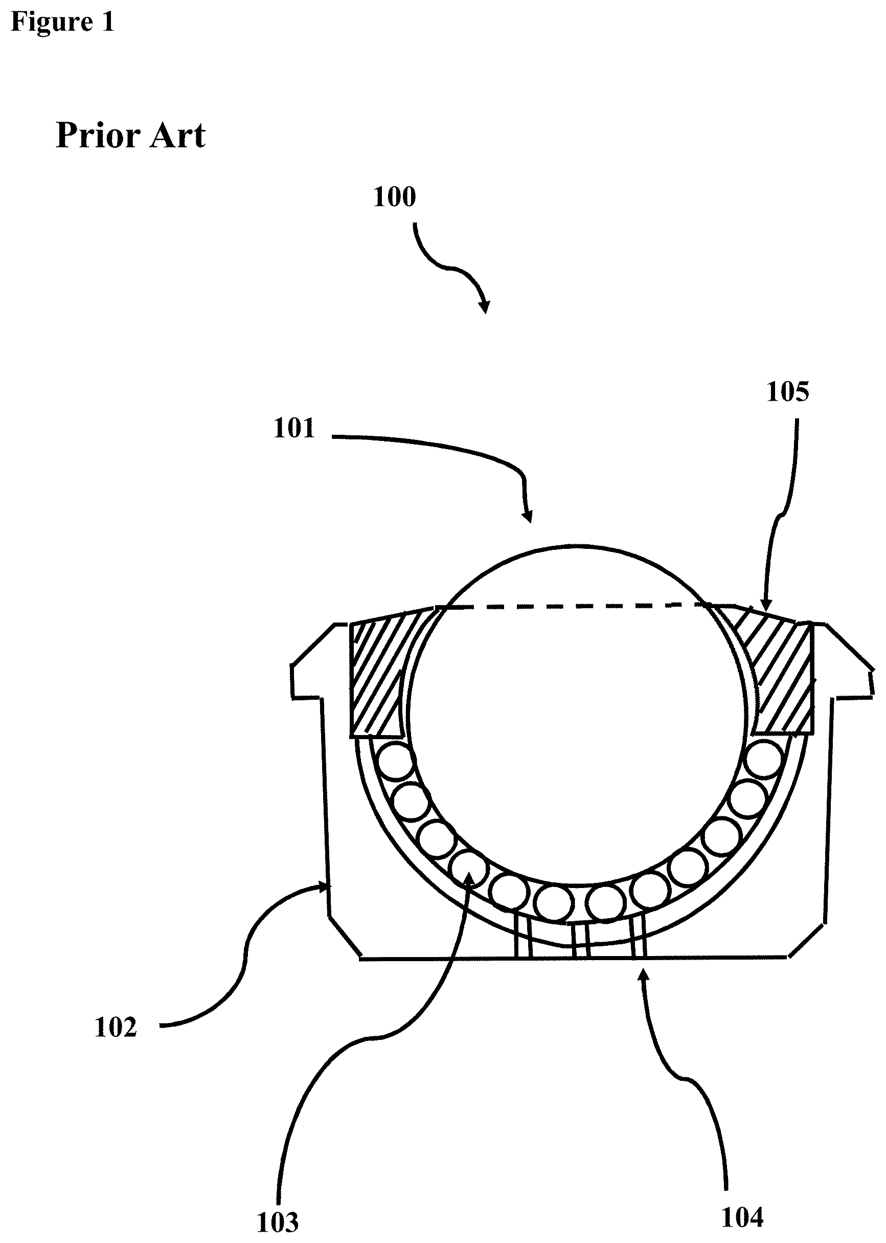
FIG. 1 depicts a cross-sectional view of a typical roller ball assembly 100 of the prior art. In assembly 100, primary roller ball 101 is supported by a series of small steel balls 103 within shaped steel cup 102. Primary steel roller ball 101 is retained by cap 105. Assembly 100 also includes small weep holes 104 for clearing liquid or minor debris.
Some assemblies do not employ smaller ball bearings as support for the primary roller ball, but rather use a direct engagement with a cup surface. In order to overcome galling problems, these designs have, in some instances, used coatings or lubricants, which require seals, or alternative roller ball materials, such as silicon nitride, tungsten carbide, silicon carbide, or ceramics. Even when coatings or alternative roller ball materials are used, the increased surface contact area of the roller ball with the cup surface increases the coefficient of friction and reduces the free rolling capability of the roller ball.
An additional significant challenge is contamination with debris, hampering the free rolling of the primary roller ball. In the support ball of existing assemblies, debris evacuation openings in the lower cup structure must be small enough to not catch or interfere with the free rolling of the secondary balls. This size limitation of the debris evacuation openings limits their effectiveness in clearing contaminants from the assembly.
Changing out failed or fouled roller ball assemblies is time consuming and disruptive to operations. This can be especially problematic in aerospace, downhole, and military logistics operations where limited access exists or failure impacts mission critical performance.
Information on roller ball bearing assemblies can be found in the "Hudson Bearings Air Cargo Roller Ball Transfers", an undated eight-page brochure, as well as in "Hudson Bearings Air Cargo Roller Ball Transfers Installation and Maintenance Protocols", an undated five-page brochure, both of which are available from the Hudson Bearings website (www.hudsonbearings.com). Of note from these brochures are the 850 lbs. maximum load capacity rating and 400.degree. F. maximum temperature range for heavy duty transfer roller ball assemblies.
An additional reference on the downhole use of roller ball assemblies is U.S. Pat. No. 9,803,432, to Wood et al., which is incorporated herein by reference in its entirety as if set out in full.
BRIEF SUMMARY
Some aspects of the present disclosure include a roller ball assembly. The assembly includes a primary roller ball that is supported by at least one support element. Each support element is composed of a superhard material.
Other aspects of the present disclosure include a cup for supporting a roller ball in a roller ball assembly. The cup includes a cup body defining a cavity. At least one support element is positioned in the cavity and coupled with the cup body. Each support element is composed of a superhard material.
Additional aspects of the present disclosure include a method of supporting a primary roller ball of a roller ball assembly. The method includes positioning at least one support element within a cavity of a cup. Each support element is composed of a superhard material. The method includes positioning the primary roller ball within the cavity such that an outer surface of the primary roller ball is in contact with an engagement surface of the at least one support element. The method includes positioning a cap relative to the cup such that the cap is positioned to retain the primary roller ball within the cavity.
BRIEF DESCRIPTION OF THE DRAWINGS
So that the manner in which the features and advantages of the systems, apparatus, and/or methods of the present disclosure may be understood in more detail, a more particular description briefly summarized above may be had by reference to the embodiments thereof which are illustrated in the appended drawings that form a part of this specification. It is to be noted, however, that the drawings illustrate only various exemplary embodiments and are therefore not to be considered limiting of the disclosed concepts as it may include other effective embodiments as well.
FIG. 1 is a cross-sectional view of a typical roller ball assembly of the prior art.
FIG. 2 is a flow chart of a method in accordance with certain aspects of the present disclosure.
FIG. 3 is a side view of an embodiment of a roller ball assembly of the present application.
FIG. 4 is a top view of a cup of a three-support element assembly of the present technology without roller ball or cap.
FIG. 5 is a side view of an alternative embodiment of the technology of this application.
FIG. 6 is a side view of an alternative embodiment of the technology of this application.
FIG. 7A is a top view of an alternative embodiment of the technology of this application without roller ball or cap.
FIG. 7B is a side view of the assembly of FIG. 7A with cap and roller ball included.
FIG. 8 is a diagram showing the location spectrum from centerline for a single support at centerline, or for multiple supports angled upwards on the cup from centerline.
Systems, apparatus, and methods according to present disclosure will now be described more fully with reference to the accompanying drawings, which illustrate various exemplary embodiments. Concepts according to the present disclosure may, however, be embodied in many different forms and should not be construed as being limited by the illustrated embodiments set forth herein. Rather, these embodiments are provided so that this disclosure will be thorough as well as complete and will fully convey the scope of the various concepts to those skilled in the art and the best and preferred modes of practice.
DETAILED DESCRIPTION
Certain aspects of the present disclosure include roller ball assemblies, apparatus including roller ball assemblies, systems including roller ball assemblies, methods of making roller ball assemblies, methods of assembling roller ball assemblies, and methods of using roller ball assemblies.
Roller Ball Assemblies Including Superhard Materials
In some embodiments, the technology of this application provides for a high-performance roller ball assembly with a moving part (optionally a single moving part), in particular a primary roller ball, supported on at least one so called "superhard" component or element (i.e., a component composed of a "superhard material"). As would be understood by one skilled in the art, "superhard materials" are a category of materials defined by the hardness of the material, which may be determined in accordance with the Brinell, Rockwell, Knoop and/or Vickers scales. For example, superhard materials include materials with a hardness value exceeding 40 gigapascals (GPa) when measured by the Vickers hardness test. As used herein, superhard materials include materials that are at least as hard as tungsten carbide tiles and/or cemented tungsten carbide, such as is determined in accordance with one of these hardness scales, such as the Brinell scale. One skilled in the art would understand that a Brinell scale test may be performed, for example, in accordance with ASTM E10-14; the Vickers hardness test may be performed, for example, in accordance with ASTM E384; the Rockwell hardness test may be performed, for example, in accordance with ASTM E18; and the Knoop hardness test may be performed, for example, in accordance with ASTM E384. The "superhard materials" disclosed herein include, but are not limited to, tungsten carbide (e.g., tile or cemented), infiltrated tungsten carbide matrix, silicon carbide, silicon nitride, cubic boron nitride, and polycrystalline diamond.
Thus, some aspects of the present disclosure include employing discrete superhard elements to support a roller ball. In certain aspects of the technology of this application, the need for small diameter support balls in a roller ball assembly is eliminated. Thus, at least some of the roller ball assemblies disclosed herein lack (i.e., do not include) small diameter support balls.
In certain embodiments, the roller ball assemblies disclosed herein have a higher load bearing capacity, higher temperature capacity, are more durable, are more corrosion resistant, are smoother running, and have a greater capacity for the passing of contaminants and larger debris from the working area of the assembly in comparison to existing roller ball assemblies.
In some aspects, the roller ball assemblies disclosed herein "self-clean" any corrosion on the primary roller ball. As the surface of the primary roller ball moves, while engaged with the surface of the polycrystalline diamond elements, existing corrosion on the primary roller ball may be at least partially removed therefrom via the frictional forces resulting from the engagement between the surfaces of the primary roller ball and the polycrystalline diamond elements. That is, the polycrystalline diamond elements clean, sweep, or rub off at least some of the corroded material of the primary roller ball. In contrast, roller ball assemblies such as is shown in FIG. 1 include primary roller balls that "roll" on other, small roller balls, which do not function to remove corroded material from the primary roller ball.
In certain embodiments, the technology of this application includes a roller ball assembly suitable for application in harsh environments (e.g., downhole environments). The technology of this application includes a roller ball assembly capable of application in downhole drilling applications in the mitigation of torque and drag.
Exemplary Testing
Applicants of the present application have conducted significant testing on an exemplary roller ball assembly that provides an ultra-high-performance alternative in comparison to existing technology. Table 1, below, sets forth a summary of a test performed by the Applicants of an exemplary configuration of a roller ball assembly of the present disclosure.
TABLE-US-00001 TABLE 1 Tested Mechanism - Bearing Steel Ball in Alloy Steel Cup Against Rotating Surface Steel Cam Surface RPM Speed Loading Result Test Tripod Polished 200 1.13 m/s 700 lbf 20 hr. test, PDC 1.50'' Ball little wear on Ball; slight Hertzian trace on PDCs
FIG. 2 sets forth the steps of the testing performed, which included: supporting a single 11/2'' high-carbon steel roller ball on three polycrystalline diamond (PDC) elements, box 290; deploying the supported roller ball in a steel cup, box 291; subjecting the deployed roller ball to 20 hours of rotating test under 700 lbf of load, box 292; and assessing wear roller ball and PDC elements, box 293. As is evident from Table 1, the testing resulted in little wear on the roller ball and only a slight Hertzian trace of discoloration on the PDC elements.
In further testing, 800 lbs of load on the primary roller ball of a prior art roller ball assembly was found to produce 525,000 PSI max stress on the associated support ball. Whereas, in an exemplary roller ball assembly in accordance with the present disclosure, 1,600 lbs of load on the primary roller ball was required to produce the same 525,000 PSI max stress on the associated superhard element. Consequently, without being bound by theory, the technology disclosed herein exhibited twice the load bearing capacity in comparison to the prior art roller ball assembly.
Turning now to FIGS. 3-8, various exemplary roller ball assemblies and aspects thereof will now be described. In FIGS. 3-8, like reference numerals refer to like elements. For example, an exemplary cup is identified with reference numeral "302" in FIG. 3 and is identified with reference numeral "402" in FIG. 4.
Roller Ball Assembly with Superhard Support Elements
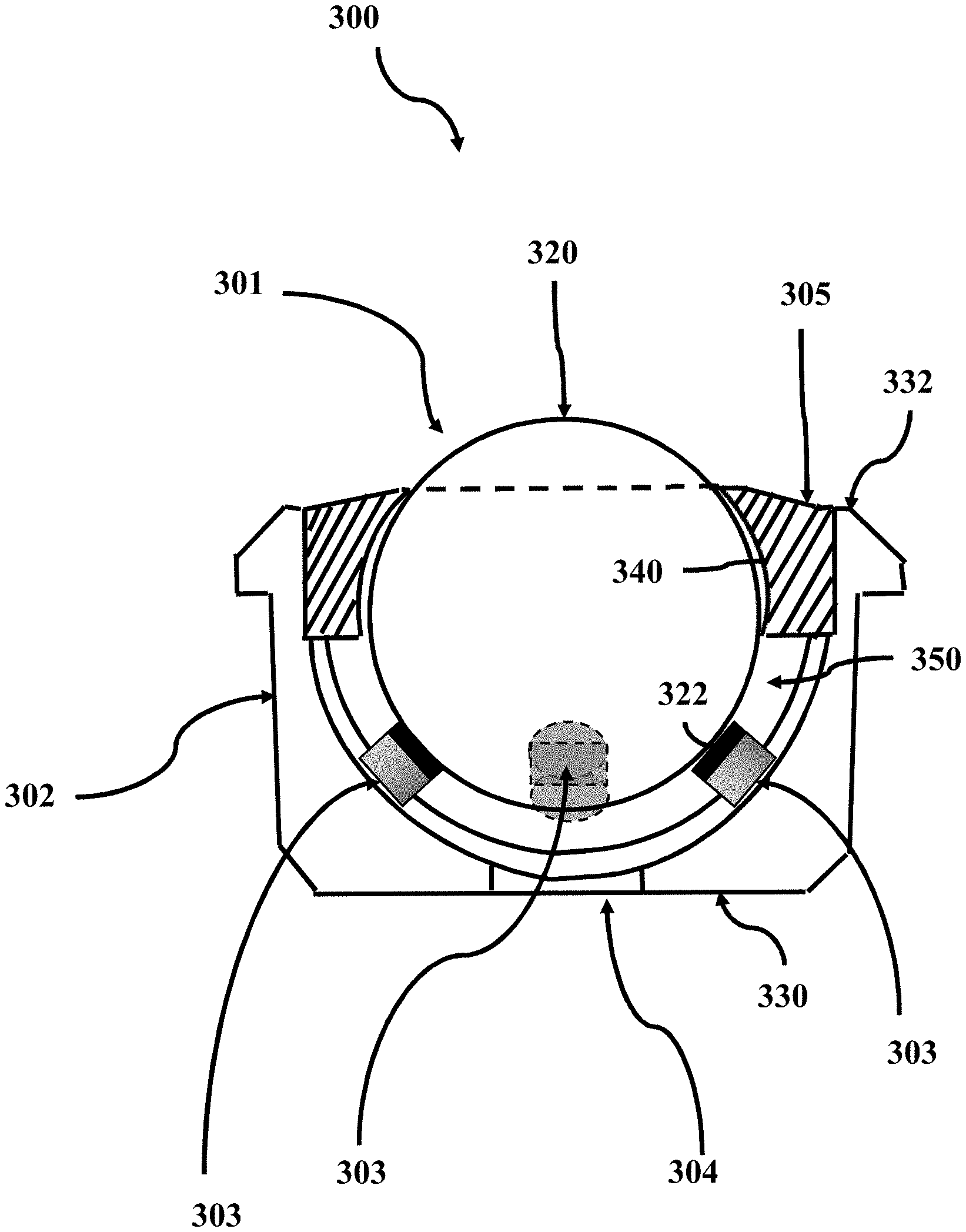
FIG. 3 is a side view of a roller ball assembly 300 in accordance with an embodiment of the present application. In assembly 300, roller ball 301 is supported within cup 302 (cup body) via support elements 303. Each support element 303 is formed of a superhard material. Roller ball 301 may be formed of any of a variety of materials including, but not limited to, steel. As shown in FIG. 3, roller ball 301 is supported by support elements 303 via contact between roller ball outer surface 320 (also referred to as engagement surface) and support element surfaces 322 (also referred to as opposing engagement surfaces). Primary roller ball 301 is clear of (i.e., not in contact with) cup 302. Support elements 303 are attached to, embedded within, or otherwise affixed to and/or coupled with or within cup 302. In contrast to small support roller balls, such as is shown in FIG. 1, support elements 303 are static relative to cup 302. In operation, primary roller ball 301 moves in sliding contact with support elements 303.
Cup 302, also referred to as "shaped cup", has a shape that defines a cavity 350 configured to receive roller ball 301 therein, and to allow rolling of roller ball 301 therein. Cup 302 may be formed on any of a variety of materials including, but not limited to, steel.
Assembly 300 includes cap 305. Cap 305 is positioned relative to cup 302 to retain primary roller ball 301 within cup 302. Cap 305 is engaged and/or coupled (e.g., affixed) with cup 302 at top end 332 of cup 302. Cap 305 has a curvature 340 sufficient to retain roller ball 301 within cup 302 such that, in operation, roller ball 301 is supported via support elements 303 and freely rolls within cup 302 while being retained therein by cap 305. Cap 305 is clear of (i.e., not in contact with) primary roller ball 301. Cap 305 may be formed on any of a variety of materials including, but not limited to, steel. Cap 305 may be, for example, in the form of a retainer ring.
Assembly 300 includes debris clearance hole 304 positioned at the bottom end 330 of cup 302. Hole 304 may be sized and arranged for clearance of large debris from cup 302. Contrary to the hole 204 of FIG. 1, hole 304 is not limited in size by the presence of small supporting roller balls that would fall through the hole if the hole were too large. Thus, while hole 304 may be as small or smaller than hole 204, hole 304 may also be larger, even significantly larger, than hole 204. For example, hole 304 may be up to about half the size of primary roller ball 301 (e.g., half the diameter), or from about 1/8 to about 1/2 the size (e.g., diameter) of primary roller ball 301, or from about 1/4 to about 1/2 the size (e.g., diameter) of primary roller ball 301.
One skilled in the art would understand that the roller ball assembly disclosed herein is not limited to the particular arrangement shown in FIG. 3 (or FIGS. 4-8). For example, the roller ball assembly may include more or less than three support elements, which may be arranged, sized, and positioned in numerous configurations.
Cup Assembly
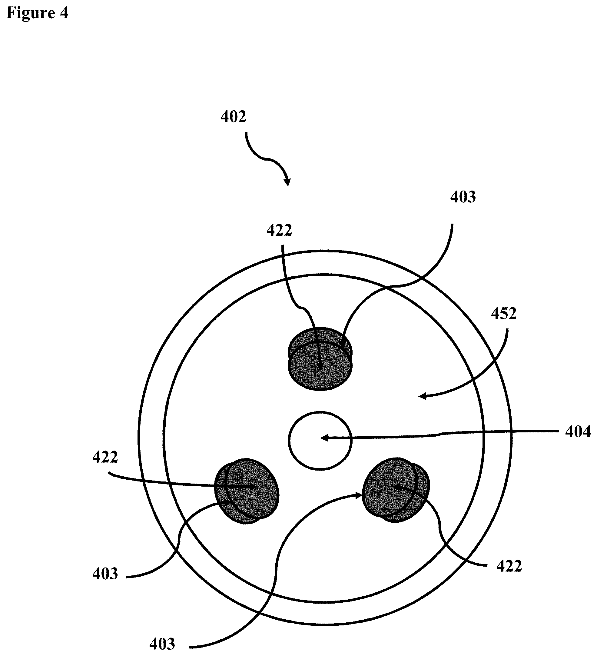
FIG. 4 is a top view of a cup that includes a three-support element assembly (i.e., three support elements, 403) in accordance with certain aspects of the present technology. Cup 402 is shown in FIG. 4 without a roller ball engaged therein and without a cap engaged thereon.
Support elements 403, formed of a superhard material, are deployed and positioned within cup 402. Support elements 403 may be coupled to, with, or within cavity surface 452 of cup 402 via any of a variety of methods, as is known in the art. Debris clearance hole 404 is positioned at the bottom end of cup 402, as a through-hole through cavity surface 452.
While shown as evenly spaced in FIG. 4, one skilled in the art would understand that support elements 403 may be spaced unevenly.
Roller Ball Assembly with Superhard Support and Retention Elements
FIG. 5 shows a side view of roller ball assembly 500, exemplifying an alternative embodiment of the technology of this application. In assembly 500, roller ball 501 is supported by support elements 503 (formed of superhard material) that are positioned within cup 502 and is further retained by retention elements 506 (formed of superhard material) deployed, positioned, and arranged on or within cap 505 such that opposing engagement surfaces 522 of both support elements 503 and retention element 506 are engaged with outer surface 520 of roller ball 501.
Retention elements 506 may be coupled to, with, or within cap 505 in the same manners as described with respect to the coupling of support elements with the cup. In certain aspects, retention elements 506 are of the same or substantially structure the same as support elements 503. As is evident in FIG. 5, support elements 503 are positioned below a hypothetical axis of rotation 560 of roller ball 501 to support downward force 570 of roller ball 501, and retention elements 506 are positioned above the hypothetical axis of rotation 560 of roller ball 501 to support upward force 572 of roller ball 501.
As with other embodiments, assembly 500 includes debris clearance hole 504 positioned at the bottom end 530 of cup 502.
FIG. 6 depicts a side view of roller ball assembly 600 in accordance with an alternative embodiment of the technology of this application. In assembly 600, roller ball 601 is supported by support elements 603 and additional support elements 607, each formed of superhard material and positioned within cup 602; and is retained by retention elements 606, which is formed of superhard material and is deployed and positioned in cap 605. Debris clearance hole 604 is deployed at the bottom end 630 of cup 602. Each of support elements 603, additional support elements 607, and retention elements 606 has an engagement surface 622 in sliding contact with outer surface 620 of roller ball 601.
Cup Assembly with Cut Out Relief and Lubricating Element
FIG. 7A is a top view of cup 702 including a three-support element assembly (i.e., three support elements, 703) in accordance with certain aspects of the present technology. Cup 702 is shown without a roller ball engaged therein and without a cap engaged thereon.
Support elements 703, formed of superhard material, are deployed and positioned in cup 702. Debris clearance hole 704 is formed through the bottom of cup 702, through cavity surface 752.
Cup 702 includes cut out relief areas 708 formed there-through (e.g., through the frame, body, structure). Support elements 703 are positioned between cut out relief areas 708. Cut out relief areas 708 may be holes formed through cavity surface 752 and may allow debris to pass there-through.
Cup 702 also includes lubricating element 709 positioned to provide a lubricant within cup 702, between cup 702 and any roller ball that is positioned therein, such as between engagement surfaces of support elements 703 and the outer surface of a roller ball.
FIG. 7B shows a side view of roller ball assembly 700, which includes cup 702 with support elements 703, debris clearance hole 704, cut out relief areas 708, and lubricating element 709 as shown in FIG. 7A, with the addition of primary roller ball 701 and cap 705 (retaining cap).
In assembly 700, roller ball 701 is supported within cup 702 via support elements 703, which are formed of superhard material, and is retained within cup 702 via cap 705. In operation, as roller ball 701 rolls in sliding contact with engagement surface 722 within cup 702, relief areas 708 and hole 704 allow for debris fall out there-through.
Lubricating element 709 is engaged with (e.g., pressed against) outer surface 720 of primary roller ball 701. Energizer 710, which may be a bias member, such as a spring, presses lubricating element 709 into engagement with outer surface 720 of roller ball 701. Thus, lubricating element 709 is positioned to apply lubricant to outer surface 720 of roller ball 701. In some aspects, the lubricant is any one of a number of solid lubricants including but not limited to: graphite, hexagonal boron nitride, oil releasing polymer, molybdenum disulfide, or tungsten disulfide. In some aspects, energizer 710 is a coil spring, a Belleville spring, an elastomer, or other applicable energizing element.
Although FIGS. 7A and 7B show cap 705 without superhard retention elements, it would be clear to one skilled in the art that a cap containing superhard retention elements, such as shown in FIGS. 5 and 6, could be used in the assembly of FIGS. 7A and 7B.
Positioning of Superhard Supporting Elements
FIG. 8 is a representative diagram of an arc 811 identifying positions where supporting elements of superhard material may be deployed within a cup in accordance with certain aspects of the technology of the present application. Arc 811 is bisected by vertical centerline 814. Arc 811 corresponds with the bottom, cavity surface of a cup of a roller ball assembly, as indicated via 852. Thus, centerline 814 corresponds with the centerline of a cup of a roller ball assembly or with the centerline of the roller ball of a roller ball assembly.
In embodiments where a single support element formed of superhard material is deployed, support element 812 is deployed as the support element at the base of arc 811 with the face 822a (engagement surface formed of superhard material) arranged and positioned perpendicular to centerline 814.
In embodiments where more than one support element formed of superhard material are deployed, support elements 813 (formed of superhard material) are deployed at positions that are generally equidistant from centerline 814 and at an arc angle from centerline 814 along arc 811. A generally minimum angle for deployment of multiple superhard support elements is shown at C. The value for angle C is about 20.degree. from centerline 814. A more preferred spectrum of angles for deployment of superhard support elements is shown by angles D and E, which are from about 30.degree. at D to about 50.degree. at E, both from centerline 814. A generally maximum angle for deployment of multiple superhard support elements is shown at F. The value for angle F is about 60.degree. from centerline 814. It would be understood by those skilled in the art that the angles shown in FIG. 8 apply to the primary superhard support elements and do not apply to additional superhard retention elements that may be deployed in a retaining cap or ring of a roller ball assembly.
Roller Ball
In the practice of the technology of this application, the primary roller ball is preferably stainless steel or hard carbon steel, but may, alternatively, be tungsten carbide, silicon carbide, silicon nitride, alternative ceramics, nylon or any other bearing ball material as known in the art.
Support of the Roller Ball
Although superhard components are typically more expensive (financially) than existing small diameter support roller balls, the technology of the present application offers clear advantages over existing primary roller ball supports. The roller ball assembly technology of the present application includes, in some instances, only a single moving part, i.e., the primary roller ball, with no other moving parts in the roller ball assembly. The engagement of the primary roller ball with the superhard components (support and retention elements), especially polished PDC elements, provides for very low-friction rolling of the primary roller ball. In some aspects, the coefficient of friction (CoF) of the engagement between the primary roller ball and the PDC elements remains constant or substantially constant over relatively long terms of use, as the assembly does not rely on use of small roller balls (e.g., as shown in FIG. 1), which are subject to degradation that affects the CoF. The superhard components are also capable of higher loading than existing small diameter support roller balls.
Retaining Cap
In the embodiments disclosed herein, the retaining caps or rings (e.g., cap 205) may be held in place on the respective cup of the roller ball assembly via methods known in the art including, but not limited to, one or more snap rings, gluing, threading, welding, brazing, or press fitting the cap or ring to the cup. In some aspects, the retaining cap is designed to incorporate a debris excluding "knife edge", as is known in the art, or a sealing surface. Alternatively, the retaining cap or ring may be slotted, scalloped or gapped to allow for the free flow of fluid, such as in a downhole application of the roller ball assembly.
Mounting of Support and Retention Elements
The superhard support and retention elements deployed in the various embodiments of the technology of this application may be mounted (e.g., onto the cup and/or cap) via one or more methods, as known in the art, including but not limited to brazing, gluing, threading, or press fitting the superhard support and retention elements to the cap or cup.
Superhard Materials
Although the technology of this application is broad enough to include the use of a range of superhard materials, in some applications the preferred superhard material is PDC. While polished PDC is preferred in the technology of the present application, the PDC employed in this technology may be lapped, highly lapped, polished, or highly polished. U.S. Pat. Nos. 5,447,208 and 5,653,300, to Lund et al., provide disclosure related to PDC and the surface finish thereof. The disclosures of U.S. Pat. Nos. 5,447,208 and 5,653,300 are incorporated herein by reference and made a part of the present disclosure. As used herein, a surface is defined as "highly lapped" if the surface has a surface finish of 20 .mu.in or about 20 .mu.in, such as a surface finish ranging from about 18 to about 22 .mu.m. As used herein, a surface is defined as "polished" if the surface has a surface finish of less than about 10 .mu.m, or of from about 2 to about 10 .mu.in. As used herein, a surface is defined as "highly polished" if the surface has a surface finish of less than about 2 .mu.m, or from about 0.5 .mu.m to less than about 2 .mu.m. In some aspects, engagement surface has a surface finish ranging from 0.5 .mu.in to 40 .mu.in, or from 2 .mu.m to 30 .mu.in, or from 5 .mu.in to 20 .mu.m, or from 8 .mu.in to 15 .mu.m, or any range therebetween. In some aspects, engagement surface has a surface finish of less than 40 .mu.m, less than 30 .mu.m, less than 20 .mu.m, less than 15 .mu.m, less than 10 .mu.m, less than 8 .mu.in, less than 5 .mu.m, or less than 2 .mu.m. Polycrystalline diamond that has been polished to a surface finish of 0.5 .mu.m has a coefficient of friction that is about half of standard lapped polycrystalline diamond with a surface finish of 20-40 .mu.m.
Thus, in some aspects, the technology disclosed herein incorporates the use of superhard elements, preferably polished polycrystalline diamond compact (PDC) elements, to support the primary roller ball of a roller ball assembly.
Arrangement and Configuration of Superhard Support and/or Retention Elements
In one preferred embodiment, three planar superhard support elements are complimentarily deployed in a metal cup or frame. In operation, the superhard support elements provide the primary support for the roller ball. Several alternatives are possible for the supporting elements of the technology of this application including an increased or decreased number of superhard support elements. For example, a single superhard support element may be deployed in the bottom of the metal cup to support the roller ball.
Although planar superhard support elements are preferred, non-planar, including concave or convex, superhard support elements may be used.
The upper girth of the roller ball may be contained (retained) by a number of materials or combinations of materials as known in the art including, but not limited to, polypropylene, Kevlar, metal, felt, leather, or Teflon. However, in an enhanced embodiment, the upper portion of the roller ball is contained (retained) by an additional set of superhard, preferably polished PDC elements (i.e., retention elements), secured on an inner surface or bosses of a cap of metal or other appropriate material.
The superhard components (support or retention elements) of the present technology may generally be as small as 1/8'' (about 3 mm) in diameter or as large as 3/4'' (about 19 mm) in diameter. For smaller precision applications, significantly smaller diameter support and retention elements and smaller primary ball diameters may be used. As would be understood by one skilled in the art, the technology of the present application may be scaled up or down without departing from the primary technology. When two or more superhard components are used to support the transfer roller ball, the superhard components are typically, although not necessarily, located equidistant from the assembly centerline (as shown and described with reference to FIG. 8).
As would be understood by one skilled in the art, the various aspects disclosed herein may be combined in any of numerous combinations without departing from the scope of this disclosure. For example, a roller ball assembly that includes a primary roller ball supported on at least one support element that is formed of a superhard material may further include: at least one retention element formed of a superhard material; at least one additional support element formed of a superhard material; at least one large debris clearance hole; at least one lubricating element; or any combination thereof.
From the descriptions and figures provided above it can readily be understood that the technology of the present application may be employed in a broad spectrum of applications, including those in downhole environments. The technology provided herein additionally has broad application to other industrial applications.
Furthermore, while shown and described in relation to engagement between the surface of a roller ball and the surface of a support element that includes superhard material, one skilled in the art would understand that the present disclosure is not limited to this particular application and that the concepts disclosed herein may be applied to the engagement between any surface (e.g., steel surface) that is engaged with the surface of a superhard material.
Although the present embodiments and advantages have been described in detail, it should be understood that various changes, substitutions and alterations can be made herein without departing from the spirit and scope of the disclosure. Moreover, the scope of the present application is not intended to be limited to the particular embodiments of the process, machine, manufacture, composition of matter, means, methods and steps described in the specification. As one of ordinary skill in the art will readily appreciate from the disclosure, processes, machines, manufacture, compositions of matter, means, methods, or steps, presently existing or later to be developed that perform substantially the same function or achieve substantially the same result as the corresponding embodiments described herein may be utilized according to the present disclosure. Accordingly, the appended claims are intended to include within their scope such processes, machines, manufacture, compositions of matter, means, methods, or steps.
* * * * *
References
-
en.wikipedia.org/w/index.php?title=Linear-motion_bearing&oldid=933640111
-
popularmechanics.com/science/environment/a28970718/superhard-materials
-
-
-
-
D00000
D00001
D00002
D00003
D00004
D00005
D00006
D00007
D00008
XML
uspto.report is an independent third-party trademark research tool that is not affiliated, endorsed, or sponsored by the United States Patent and Trademark Office (USPTO) or any other governmental organization. The information provided by uspto.report is based on publicly available data at the time of writing and is intended for informational purposes only.
While we strive to provide accurate and up-to-date information, we do not guarantee the accuracy, completeness, reliability, or suitability of the information displayed on this site. The use of this site is at your own risk. Any reliance you place on such information is therefore strictly at your own risk.
All official trademark data, including owner information, should be verified by visiting the official USPTO website at www.uspto.gov. This site is not intended to replace professional legal advice and should not be used as a substitute for consulting with a legal professional who is knowledgeable about trademark law.