Method and device for determining and presenting surface charge and dipole densities on cardiac walls
Scharf , et al. May 25, 2
U.S. patent number 11,013,444 [Application Number 16/533,028] was granted by the patent office on 2021-05-25 for method and device for determining and presenting surface charge and dipole densities on cardiac walls. This patent grant is currently assigned to Christoph Scharf. The grantee listed for this patent is Christoph Scharf. Invention is credited to Christoph Scharf, Gunter Scharf.


View All Diagrams
| United States Patent | 11,013,444 |
| Scharf , et al. | May 25, 2021 |
Method and device for determining and presenting surface charge and dipole densities on cardiac walls
Abstract
The invention discloses a method, a system, a computer program and a device for determining the surface charge and/or dipole densities on heart walls. Using the foregoing, a table of dipole densities .nu.(P', t) and/or a table of surface charge densities .rho.(P', t) of a given heart chamber can be generated.
| Inventors: | Scharf; Christoph (Zurich, CH), Scharf; Gunter (Zurich, CH) | ||||||||||
|---|---|---|---|---|---|---|---|---|---|---|---|
| Applicant: |
|
||||||||||
| Assignee: | Scharf; Christoph
(N/A) |
||||||||||
| Family ID: | 38997497 | ||||||||||
| Appl. No.: | 16/533,028 | ||||||||||
| Filed: | August 6, 2019 |
Prior Publication Data
| Document Identifier | Publication Date | |
|---|---|---|
| US 20200187801 A1 | Jun 18, 2020 | |
Related U.S. Patent Documents
| Application Number | Filing Date | Patent Number | Issue Date | ||
|---|---|---|---|---|---|
| 16014370 | Jun 21, 2018 | 10413206 | |||
| 15435763 | Feb 17, 2017 | 10376171 | |||
| 14865435 | Apr 4, 2017 | 9610024 | |||
| 14547258 | Oct 27, 2015 | 9167982 | |||
| 14189643 | Dec 23, 2014 | 8918158 | |||
| 13858715 | Apr 15, 2014 | 8700119 | |||
| 12376270 | Apr 9, 2013 | 8417313 | |||
| PCT/CH2007/000380 | Aug 3, 2007 | ||||
Foreign Application Priority Data
| Aug 3, 2006 [CH] | 1251/06 | |||
| Current U.S. Class: | 1/1 |
| Current CPC Class: | A61B 5/287 (20210101); A61B 5/349 (20210101); G16H 50/50 (20180101); A61B 5/363 (20210101); G16H 20/10 (20180101); A61B 5/339 (20210101); A61B 5/1075 (20130101); G16H 20/40 (20180101); G16Z 99/00 (20190201); A61B 5/316 (20210101); G16H 20/60 (20180101); A61B 5/283 (20210101); A61B 5/282 (20210101); A61B 5/0205 (20130101); A61B 5/1076 (20130101); A61B 5/318 (20210101); A61B 5/333 (20210101); A61B 2090/374 (20160201); A61B 2090/3762 (20160201); A61B 2562/0214 (20130101) |
| Current International Class: | A61B 5/0205 (20060101); A61B 5/107 (20060101); G16H 50/50 (20180101); G16H 20/10 (20180101); A61B 5/333 (20210101); A61B 5/349 (20210101); A61B 5/363 (20210101); A61B 5/318 (20210101); A61B 5/316 (20210101); A61B 5/287 (20210101); A61B 5/282 (20210101); G16H 20/40 (20180101); G16H 20/60 (20180101); A61B 5/283 (20210101); A61B 5/339 (20210101); A61B 90/00 (20160101) |
References Cited [Referenced By]
U.S. Patent Documents
| 4173228 | November 1979 | Van Steenwyk et al. |
| 5041973 | August 1991 | Lebron et al. |
| 5156151 | October 1992 | Imran |
| 5293868 | March 1994 | Nardella |
| 5482472 | January 1996 | Garoni et al. |
| 5499981 | March 1996 | Kordis |
| 5555883 | September 1996 | Avitall |
| 5595183 | January 1997 | Swanson et al. |
| 5601084 | February 1997 | Sheehan et al. |
| 5647367 | July 1997 | Lum et al. |
| 5662108 | September 1997 | Budd et al. |
| 5722402 | March 1998 | Swanson et al. |
| 5722416 | March 1998 | Swanson et al. |
| 5740808 | April 1998 | Panescu et al. |
| 5749833 | May 1998 | Hakki et al. |
| 5759158 | June 1998 | Swanson |
| 5782239 | July 1998 | Webster, Jr. |
| 5795298 | August 1998 | Vesley et al. |
| 5795299 | August 1998 | Eaton et al. |
| 5820568 | October 1998 | Willis |
| 5830144 | November 1998 | Vesely |
| 5846198 | December 1998 | Killmann |
| 5876336 | March 1999 | Swanson et al. |
| 5928228 | July 1999 | Kordis et al. |
| 5944022 | August 1999 | Nardella et al. |
| 5968040 | October 1999 | Swanson et al. |
| 6014590 | January 2000 | Whayne et al. |
| 6024703 | February 2000 | Zanelli et al. |
| 6066096 | May 2000 | Smith et al. |
| 6086532 | July 2000 | Panescu et al. |
| 6107699 | August 2000 | Swanson |
| 6115626 | September 2000 | Whayne et al. |
| 6187032 | February 2001 | Ohyu et al. |
| 6188928 | February 2001 | Noren et al. |
| 6216027 | April 2001 | Willis et al. |
| 6216043 | April 2001 | Swanson et al. |
| 6240307 | May 2001 | Beatty et al. |
| 6301496 | October 2001 | Reisfeld |
| 6396198 | May 2002 | Okimura et al. |
| 6400981 | June 2002 | Govari |
| 6490474 | December 2002 | Willis et al. |
| 6514249 | February 2003 | Maguire et al. |
| 6574492 | June 2003 | Ben-Haim et al. |
| 6640119 | October 2003 | Budd et al. |
| 6716166 | April 2004 | Govari |
| 6728562 | April 2004 | Budd et al. |
| 6772004 | August 2004 | Rudy |
| 6773402 | August 2004 | Govari et al. |
| 6824515 | November 2004 | Suorsa et al. |
| 6826420 | November 2004 | Beatty et al. |
| 6826421 | November 2004 | Beatty et al. |
| 6839588 | January 2005 | Rudy |
| 6895267 | May 2005 | Panescu et al. |
| 6939309 | September 2005 | Beatty et al. |
| 6950689 | September 2005 | Willis et al. |
| 6970733 | November 2005 | Willis et al. |
| 6978168 | December 2005 | Beatty et al. |
| 6990370 | January 2006 | Beatty et al. |
| 7187964 | March 2007 | Khoury |
| 7187973 | March 2007 | Hauck |
| 7258674 | August 2007 | Hillstead et al. |
| 7263397 | August 2007 | Hauck et al. |
| 7285119 | October 2007 | Stewart et al. |
| 7289843 | October 2007 | Beatty et al. |
| 7291146 | November 2007 | Steinke et al. |
| 7351914 | April 2008 | Kaneto et al. |
| 7479141 | January 2009 | Kleen et al. |
| 7505810 | March 2009 | Harlev et al. |
| 7536218 | May 2009 | Govari et al. |
| 7573182 | August 2009 | Savage |
| 7689261 | March 2010 | Mohr et al. |
| 7766838 | August 2010 | Yagi et al. |
| 7841986 | November 2010 | He et al. |
| 7918793 | April 2011 | Altmann et al. |
| 7953475 | May 2011 | Harlev et al. |
| 8103327 | January 2012 | Harlev et al. |
| 8147486 | April 2012 | Honour et al. |
| 8150499 | April 2012 | Gelbart et al. |
| 8175680 | May 2012 | Panescu |
| 8200314 | June 2012 | Bladen et al. |
| 8208998 | June 2012 | Beatty et al. |
| 8221411 | July 2012 | Francischelli et al. |
| 8233972 | July 2012 | Zhang |
| 8311613 | November 2012 | Danehorn |
| 8320711 | November 2012 | Altmann et al. |
| 8346339 | January 2013 | Kordis et al. |
| 8360786 | January 2013 | Duryea |
| 8364234 | January 2013 | Kordis et al. |
| 8412307 | April 2013 | Willis et al. |
| 8417313 | April 2013 | Scharf et al. |
| 8428690 | April 2013 | Li et al. |
| 8447377 | May 2013 | Harlev et al. |
| 8454596 | June 2013 | Ma et al. |
| 8465433 | June 2013 | Zwirn |
| 8478388 | July 2013 | Nguyen et al. |
| 8512255 | August 2013 | Scharf et al. |
| 8571647 | October 2013 | Harlev et al. |
| 8700119 | April 2014 | Scharf et al. |
| 8755861 | June 2014 | Harlev et al. |
| 8825130 | September 2014 | Just et al. |
| 8825134 | September 2014 | Danehorn |
| 8918158 | December 2014 | Scharf et al. |
| 8934988 | January 2015 | Persson et al. |
| 8948837 | February 2015 | Harlev et al. |
| 8968299 | March 2015 | Kauphusman et al. |
| 8979839 | March 2015 | De La Rama et al. |
| 8989842 | March 2015 | Li et al. |
| 9011423 | April 2015 | Brewster et al. |
| 9023027 | May 2015 | Bar-Tal et al. |
| 9026196 | May 2015 | Curran et al. |
| 9031642 | May 2015 | Ghosh |
| 9037259 | May 2015 | Mathur |
| 9044245 | June 2015 | Condie et al. |
| 9167982 | October 2015 | Scharf et al. |
| 9186081 | November 2015 | Afonso et al. |
| 9186212 | November 2015 | Nabutovsky et al. |
| 9192318 | November 2015 | Scharf et al. |
| 9220432 | December 2015 | Bukhman |
| 9241687 | January 2016 | McGee |
| 9351789 | May 2016 | Novichenok et al. |
| D758596 | June 2016 | Perryman et al. |
| 9358398 | June 2016 | Moffitt et al. |
| 9380953 | July 2016 | Houben et al. |
| 9474486 | October 2016 | Eliason et al. |
| 9480525 | November 2016 | Lopes et al. |
| 9486355 | November 2016 | Gustus et al. |
| 9492227 | November 2016 | Lopes et al. |
| 9492228 | November 2016 | Lopes et al. |
| 9498192 | November 2016 | Hashimshony et al. |
| 9504395 | November 2016 | Scharf et al. |
| 9526573 | December 2016 | Lopes et al. |
| 9549708 | January 2017 | Mercanzini et al. |
| 9579149 | February 2017 | Kelly et al. |
| D782686 | March 2017 | Werneth et al. |
| 9585588 | March 2017 | Marecki et al. |
| 9603651 | March 2017 | Ghosh |
| 9610024 | April 2017 | Scharf et al. |
| 9675266 | June 2017 | Afonso et al. |
| 9713730 | July 2017 | Mathur et al. |
| 9717555 | August 2017 | Chan et al. |
| 9717559 | August 2017 | Ditter et al. |
| 9730602 | August 2017 | Harlev et al. |
| 9757044 | September 2017 | Scharf et al. |
| 9827039 | November 2017 | Dandler et al. |
| 9901303 | February 2018 | Olson |
| 9913589 | March 2018 | Scharf et al. |
| 9968268 | May 2018 | Scharf et al. |
| 10004459 | June 2018 | Werneth et al. |
| 10028706 | July 2018 | Brockway et al. |
| 10082395 | September 2018 | Koyrakh et al. |
| 10201311 | February 2019 | Chou et al. |
| 10405828 | September 2019 | Deladi et al. |
| 2001/0007070 | July 2001 | Stewart et al. |
| 2002/0026118 | February 2002 | Govari |
| 2002/0045810 | April 2002 | Ben-Haim |
| 2002/0128565 | September 2002 | Rudy |
| 2002/0165441 | November 2002 | Coleman et al. |
| 2003/0036696 | February 2003 | Willis et al. |
| 2003/0065271 | April 2003 | Khoury |
| 2003/0078494 | April 2003 | Panescu et al. |
| 2003/0120318 | June 2003 | Hauck |
| 2003/0153907 | August 2003 | Suorsa et al. |
| 2003/0158477 | August 2003 | Panescu |
| 2003/0176799 | September 2003 | Beatty et al. |
| 2003/0231789 | December 2003 | Willis et al. |
| 2003/0236466 | December 2003 | Tarjan et al. |
| 2004/0039312 | February 2004 | Hillstead et al. |
| 2004/0082870 | April 2004 | Rudy et al. |
| 2004/0082948 | April 2004 | Stewart et al. |
| 2004/0254437 | December 2004 | Hauck et al. |
| 2005/0059880 | March 2005 | Mathias et al. |
| 2005/0101874 | May 2005 | Beatty et al. |
| 2005/0113665 | May 2005 | Mohr et al. |
| 2005/0148836 | July 2005 | Kleen et al. |
| 2005/0203375 | September 2005 | Willis et al. |
| 2006/0052716 | March 2006 | Beatty et al. |
| 2006/0058663 | March 2006 | Willis et al. |
| 2006/0058676 | March 2006 | Yagi et al. |
| 2006/0058692 | March 2006 | Beatty et al. |
| 2006/0058693 | March 2006 | Beatty et al. |
| 2006/0084884 | April 2006 | Beatty et al. |
| 2006/0084970 | April 2006 | Beatty et al. |
| 2006/0084971 | April 2006 | Beatty et al. |
| 2006/0084972 | April 2006 | Beatty et al. |
| 2006/0116576 | June 2006 | McGee et al. |
| 2006/0244177 | November 2006 | Kaneto et al. |
| 2007/0016007 | January 2007 | Govari et al. |
| 2007/0055150 | March 2007 | Donaldson et al. |
| 2007/0060832 | March 2007 | Levin |
| 2007/0083194 | April 2007 | Kunis et al. |
| 2007/0106146 | May 2007 | Altmann et al. |
| 2007/0167722 | July 2007 | Bladen et al. |
| 2007/0219551 | September 2007 | Honour et al. |
| 2007/0232949 | October 2007 | Saksena |
| 2008/0009758 | January 2008 | Voth |
| 2008/0146937 | June 2008 | Lee et al. |
| 2008/0287777 | November 2008 | Li et al. |
| 2008/0319297 | December 2008 | Danehorn |
| 2009/0024086 | January 2009 | Zhang et al. |
| 2009/0076483 | March 2009 | Danehorn |
| 2009/0082691 | March 2009 | Denison et al. |
| 2009/0131930 | May 2009 | Gelbart et al. |
| 2009/0143651 | June 2009 | Kallback et al. |
| 2009/0148012 | June 2009 | Altmann et al. |
| 2009/0171274 | July 2009 | Harlev et al. |
| 2009/0264781 | October 2009 | Scharf et al. |
| 2010/0023004 | January 2010 | Francischelli et al. |
| 2010/0076426 | March 2010 | de la Rama et al. |
| 2010/0094279 | April 2010 | Kauphusman et al. |
| 2010/0168578 | July 2010 | Garson, Jr. et al. |
| 2010/0256627 | October 2010 | Ma et al. |
| 2010/0279263 | November 2010 | Duryea |
| 2010/0286551 | November 2010 | Harlev et al. |
| 2010/0298690 | November 2010 | Scharf et al. |
| 2011/0045130 | February 2011 | Edens et al. |
| 2011/0077526 | March 2011 | Zwirn |
| 2011/0092809 | April 2011 | Nguyen et al. |
| 2011/0118726 | May 2011 | De La Rama et al. |
| 2011/0125172 | May 2011 | Gelbart et al. |
| 2011/0144510 | June 2011 | Ryu et al. |
| 2011/0172658 | July 2011 | Gelbart et al. |
| 2011/0201951 | August 2011 | Zhang |
| 2011/0213231 | September 2011 | Hall et al. |
| 2011/0270237 | November 2011 | Werneth et al. |
| 2012/0078077 | March 2012 | Harlev et al. |
| 2012/0082969 | April 2012 | Schwartz et al. |
| 2012/0123296 | May 2012 | Hashimshony et al. |
| 2012/0136231 | May 2012 | Markel |
| 2012/0143298 | June 2012 | Just et al. |
| 2012/0165667 | June 2012 | Altmann et al. |
| 2012/0172859 | July 2012 | Condie et al. |
| 2012/0184863 | July 2012 | Harlev et al. |
| 2012/0265054 | October 2012 | Olson |
| 2012/0271138 | October 2012 | Kordis et al. |
| 2012/0271139 | October 2012 | Kordis et al. |
| 2012/0277574 | November 2012 | Panescu |
| 2012/0302912 | November 2012 | Moffitt et al. |
| 2012/0310064 | December 2012 | McGee |
| 2013/0006238 | January 2013 | Ditter et al. |
| 2013/0085361 | April 2013 | Mercanzini et al. |
| 2013/0096432 | April 2013 | Hauck |
| 2013/0158537 | June 2013 | Deladi et al. |
| 2013/0165916 | June 2013 | Mathur |
| 2013/0172715 | July 2013 | Just et al. |
| 2013/0190587 | July 2013 | Lopes et al. |
| 2013/0197614 | August 2013 | Gustus et al. |
| 2013/0225983 | August 2013 | Willis et al. |
| 2013/0226017 | August 2013 | Scharf et al. |
| 2013/0241929 | September 2013 | Massarwa et al. |
| 2013/0245433 | September 2013 | Deladi et al. |
| 2013/0245621 | September 2013 | Persson et al. |
| 2013/0253298 | September 2013 | Harlev et al. |
| 2013/0267853 | October 2013 | Dausch et al. |
| 2013/0274582 | October 2013 | Afonso et al. |
| 2013/0282084 | October 2013 | Mathur et al. |
| 2013/0304062 | November 2013 | Chan et al. |
| 2013/0304065 | November 2013 | Lopes et al. |
| 2013/0310827 | November 2013 | Brewster et al. |
| 2013/0330701 | December 2013 | Rubinstein et al. |
| 2014/0024910 | January 2014 | Scharf et al. |
| 2014/0095105 | April 2014 | Koyrakh et al. |
| 2014/0121470 | May 2014 | Scharf et al. |
| 2014/0148677 | May 2014 | Liempde et al. |
| 2014/0180150 | June 2014 | Scharf et al. |
| 2014/0221803 | August 2014 | Bar-Tal et al. |
| 2014/0235988 | August 2014 | Ghosh |
| 2014/0249505 | September 2014 | Bukhman |
| 2014/0257069 | September 2014 | Eliason et al. |
| 2014/0257071 | September 2014 | Curran et al. |
| 2014/0275921 | September 2014 | Harlev et al. |
| 2014/0276733 | September 2014 | VanScoy et al. |
| 2014/0276746 | September 2014 | Nabutovsky et al. |
| 2014/0276789 | September 2014 | Dandler et al. |
| 2014/0358143 | December 2014 | Novichenok et al. |
| 2015/0038862 | February 2015 | Gijsbers et al. |
| 2015/0196217 | July 2015 | Harlev et al. |
| 2015/0196219 | July 2015 | Scharf et al. |
| 2015/0208938 | July 2015 | Houben et al. |
| 2015/0223757 | August 2015 | Werneth et al. |
| 2015/0223863 | August 2015 | Ghosh |
| 2015/0257732 | September 2015 | Ryan |
| 2015/0257825 | September 2015 | Kelly et al. |
| 2015/0342491 | December 2015 | Marecki et al. |
| 2015/0366508 | December 2015 | Chou et al. |
| 2015/0374252 | December 2015 | de la Rama et al. |
| 2016/0007869 | January 2016 | Scharf et al. |
| 2016/0038051 | February 2016 | Scharf et al. |
| 2016/0051321 | February 2016 | Salahieh et al. |
| 2016/0100770 | April 2016 | Afonso et al. |
| 2016/0128771 | May 2016 | Ditter et al. |
| 2016/0128772 | May 2016 | Reinders et al. |
| 2016/0192902 | July 2016 | Werneth et al. |
| 2016/0256112 | September 2016 | Brockway et al. |
| 2017/0035486 | February 2017 | Lopes et al. |
| 2017/0065204 | March 2017 | Ludwin et al. |
| 2017/0100049 | April 2017 | Scharf et al. |
| 2017/0202469 | July 2017 | Scharf et al. |
| 2017/0258347 | September 2017 | Scharf et al. |
| 2017/0311833 | November 2017 | Afonso et al. |
| 2017/0319180 | November 2017 | Henneken et al. |
| 2018/0055374 | March 2018 | Scharf et al. |
| 2018/0146948 | May 2018 | Chou et al. |
| 2019/0159729 | May 2019 | Chou et al. |
| 2829626 | Sep 2012 | CA | |||
| 1856123 | Nov 2006 | CN | |||
| 101048100 | Oct 2007 | CN | |||
| 201223445 | Apr 2009 | CN | |||
| 201275144 | Jul 2009 | CN | |||
| 102770085 | Nov 2012 | CN | |||
| 104462650 | Mar 2015 | CN | |||
| 1166714 | Jan 2002 | EP | |||
| 1760661 | Mar 2007 | EP | |||
| 1779787 | May 2007 | EP | |||
| 2051625 | Apr 2009 | EP | |||
| 2252203 | Nov 2010 | EP | |||
| 2683293 | Jan 2014 | EP | |||
| 2953550 | Aug 2016 | EP | |||
| 08501477 | Feb 1996 | JP | |||
| 08504333 | May 1996 | JP | |||
| 10137207 | May 1998 | JP | |||
| 11504541 | Apr 1999 | JP | |||
| 2000510030 | Aug 2000 | JP | |||
| 2000510250 | Aug 2000 | JP | |||
| 2000358299 | Dec 2000 | JP | |||
| 2001070269 | Mar 2001 | JP | |||
| 2001522288 | Nov 2001 | JP | |||
| 2002051998 | Feb 2002 | JP | |||
| 2002113004 | Apr 2002 | JP | |||
| 2002522106 | Jul 2002 | JP | |||
| 2003511098 | Mar 2003 | JP | |||
| 2004350702 | Dec 2004 | JP | |||
| 2005536313 | Dec 2005 | JP | |||
| 2006511296 | Apr 2006 | JP | |||
| 2008149132 | Jul 2008 | JP | |||
| 2009135109 | Jun 2009 | JP | |||
| 2009136679 | Jun 2009 | JP | |||
| 2011504363 | Feb 2011 | JP | |||
| 2011507656 | Mar 2011 | JP | |||
| 2013188476 | Sep 2013 | JP | |||
| 2014506171 | Mar 2014 | JP | |||
| 2014514031 | Jun 2014 | JP | |||
| 2014516723 | Jul 2014 | JP | |||
| 2016511026 | Apr 2016 | JP | |||
| 2017514553 | Jun 2017 | JP | |||
| 9406349 | Mar 1994 | WO | |||
| 9905971 | Feb 1999 | WO | |||
| 0007501 | Feb 2000 | WO | |||
| 0245608 | Jun 2002 | WO | |||
| 03026722 | Apr 2003 | WO | |||
| 2004026134 | Apr 2004 | WO | |||
| 2006060613 | Jun 2006 | WO | |||
| 2008014629 | Feb 2008 | WO | |||
| 2009065042 | May 2009 | WO | |||
| 2009090547 | Jul 2009 | WO | |||
| 2011136867 | Nov 2011 | WO | |||
| 2012068471 | May 2012 | WO | |||
| 2012092016 | Jul 2012 | WO | |||
| 2012100184 | Jul 2012 | WO | |||
| 2012100185 | Jul 2012 | WO | |||
| 2012110942 | Aug 2012 | WO | |||
| 2012122517 | Sep 2012 | WO | |||
| 2014124231 | Feb 2013 | WO | |||
| 2013101257 | Jul 2013 | WO | |||
| 2014036439 | Mar 2014 | WO | |||
| 2014130169 | Aug 2014 | WO | |||
| 2014137897 | Sep 2014 | WO | |||
| 2015038607 | Mar 2015 | WO | |||
| 2015148470 | Oct 2015 | WO | |||
| 2016183179 | Nov 2016 | WO | |||
| 2016183285 | Nov 2016 | WO | |||
| 2016183468 | Nov 2016 | WO | |||
| 2017192769 | Nov 2017 | WO | |||
| 2017192775 | Nov 2017 | WO | |||
| 2019144103 | Jul 2019 | WO | |||
| 2019217430 | Nov 2019 | WO | |||
Other References
|
Japanese Office Action dated Mar. 10, 2020 issued in corresponding Japanese Application No. 2017-559320, with machine translation to English. cited by applicant . Australian Office Action dated Mar. 16, 2020 issued in corresponding Australian Application No. 2016260522. cited by applicant . Japanese Office Action dated Mar. 17, 2020 issued in corresponding Japanese Application No. 2019-071004, with machine translation to English. cited by applicant . Anatomy Warehouse, "Axis Heart Model", 2014, pp. 1-3, at http://www.anatomywarehouse.com/axis-scientific-2-part-deluxe-life-size-h- uman-heart-a-104269. (Year: 2014). cited by applicant . Christoph Scharf et al. Declaration under 37 C.F.R. 1.132, Nov. 15, 2012. cited by applicant . Australian Examination Report dated Feb. 8, 2019 issued in corresponding Australian Application No. 2018250516. cited by applicant . Australian Examination Report dated Jun. 28, 2018 issued in corresponding Australian Patent Application No. 2014318872. cited by applicant . Australian Office Action dated Feb. 26, 2018 issued in Australian Application No. 2017201560. cited by applicant . Australian Office Action dated Jan. 26, 2019 issued in corresponding Australian Application No. 2018211348. cited by applicant . Australian Office Action dated Jul. 6, 2017 issued in corresponding Australian Application No. 2014214756. cited by applicant . Australian Office Action dated Jun. 14, 2018 issued in Australian Application No. 2014214756. cited by applicant . Australian Office Action dated Jun. 27, 2017 issued in corresponding Australian Application No. 2013308531. cited by applicant . Australian Office Action dated Mar. 17, 2018 issued in corresponding Australian Application No. 2013308531. cited by applicant . Australian Office Action dated May 30, 2016 issued in related Australian Application No. 2012225250. cited by applicant . Australian Office Action dated Sep. 21, 2016 issued in corresponding Australian Application No. 2012225250. cited by applicant . Canadian Office Action dated Apr. 26, 2017 issued in corresponding Canadian Application No. 2932956. cited by applicant . Canadian Office Action dated Apr. 27, 2016 issued in corresponding Canadian Application No. 2747859. cited by applicant . Canadian Office Action dated Dec. 22, 2015 issued in corresponding Canadian Application No. 2656898. cited by applicant . Canadian Office Action dated Jan. 22, 2018 issued in corresponding Canadian Application No. 2932956. cited by applicant . Canadian Office Action dated Mar. 30, 2017 issued in corresponding Canadian Application No. 2747859. cited by applicant . Canadian Office Action dated Nov. 27, 2017 issued in corresponding Canadian Application No. 2829626. cited by applicant . Canadian Office Action dated Nov. 7, 2018 issued in corresponding Canadian Application No. 2932956. cited by applicant . Canadian Office Action dated Oct. 29, 2018 issued in corresponding Canadian Application No. 2829626. cited by applicant . Canadian Office Action dated Oct. 4, 2013 issued in corresponding Canadian Application No. 2659898. cited by applicant . Chinese Office Action dated Apr. 17, 2017 issued in corresponding Chinese Application No. 201480018328.4. cited by applicant . Decision dated Jan. 16, 2018 issued for European Patent Application No. 09702094.5. cited by applicant . Decision dated Jan. 18, 2018 issued for European Patent Application No. 13176658.6. cited by applicant . European Office Action dated Apr. 23, 2018 issued in corresponding European Application No. 07785075.8. cited by applicant . European Office Action dated Apr. 28, 2014 issued in corresponding European Application No. 09702094.5. cited by applicant . European Office Action dated Feb. 29, 2016 issued in corresponding European Application No. 07785075.8. cited by applicant . European Office Action dated Feb. 6, 2019 issued in corresponding European Application No. 14843283.4. cited by applicant . European Office Action dated Jan. 28, 2019 issued in corresponding European Application No. 14748567.6. cited by applicant . European Office Action dated Jan. 31, 2018 issued in corresponding European Application No. 13763151.1. cited by applicant . European Office Action dated Mar. 21, 2017 issued in corresponding European Application No. 07785075.8. cited by applicant . European Office Action dated Mar. 9, 2016 issued in corresponding European Application No. 09702094.5. cited by applicant . European Office Action dated Mar. 9, 2016 issued in corresponding European Application No. 13176658.6. cited by applicant . European Office Action dated Nov. 7, 2017 issued in corresponding European Application No. 15768711. cited by applicant . Extended European Search Report dated Dec. 5, 2018 issued in corresponding European Application No. 16793622.8. cited by applicant . Extended European Search Report dated Jul. 8, 2016 issued in corresponding European Application No. 14748567.6. cited by applicant . Extended European Search Report dated Mar. 14, 2017 issued in corresponding European Application No. 14843283.4. cited by applicant . Extended European Search Report dated Oct. 18, 2017 issued in European Application No. 15768711. cited by applicant . Extended European Search Report dated Oct. 4, 2018 issued in corresponding European Application No. 16793503.0. cited by applicant . Extended European Search Report dated Sep. 29, 2014 issued in corresponding European Application No. 13176658. cited by applicant . International Search Report and Written Opinion dated Apr. 8, 2019, issued in corresponding International Application No. PCT/US19/14498. cited by applicant . International Search Report and Written Opinion dated Aug. 11, 2016 issued in corresponding International Application No. PCT/US2016/032017. cited by applicant . International Search Report and Written Opinion dated Aug. 18, 2016 issued in corresponding International Application No. PCT/US16/32420. cited by applicant . International Search Report and Written Opinion dated Aug. 4, 2017 issued in corresponding International Application No. PCT/US17/30915. cited by applicant . International Search Report and Written Opinion dated Aug. 8, 2016 issued in corresponding European Application No. PCT/US2016/031823. cited by applicant . International Search Report and Written Opinion dated Dec. 12, 2017 issued in corresponding International Application No. PCT/US2017/056064. cited by applicant . International Search Report and Written Opinion dated Jul. 23, 2019 issued in corresponding International Application No. PCT/US2019/031131. cited by applicant . International Search Report and Written Opinion dated Jun. 26, 2015 issued in International Application No. PCT/US2015/022187. cited by applicant . International Search Report and Written Opinion dated Jun. 5, 2014 issued in corresponding International Application No. PCT/US2013/057579. cited by applicant . International Search Report and Written Opinion dated Mar. 10, 2015 issued in corresponding International Application No. PCT/US14/54942. cited by applicant . Extended European Search Report dated Nov. 26, 2019 issued in corresponding European Application No. 19184148.5. cited by applicant . International Search Report and Written Opinion dated Mar. 5, 2013 issued in corresponding International Application No. PCT/US2012/028593. cited by applicant . International Search Report and Written Opinion dated May 20, 2014 issued in corresponding International Application No. PCT/US14/15261. cited by applicant . International Search Report and Written Opinion dated Sep. 25, 2017, issued in corresponding Application No. PCT/US17/30922. cited by applicant . International Search Report dated Oct. 7, 2009 issued in corresponding International Application No. PCT/IB2009/000071. cited by applicant . International Search Report dated Apr. 14, 2008 in related International Application No. PCT/CH2007/000380. cited by applicant . Invitation to Pay Additional Fees issued on Jan. 8, 2014 in corresponding International Application No. PCT/US2013/057579. cited by applicant . Japanese Notice of Allowance dated Feb. 27, 2018 issued in corresponding Japanese Application No. 2015-530101, with English language translation. cited by applicant . Japanese Notice of Allowance dated Jul. 11, 2017 issued in corresponding Japanese Application No. 2013-557-926, with English language summary. cited by applicant . Japanese Notice of Allowance dated Jun. 11, 2019 issued in corresponding Japanese Application No. 2018-024907, with English translation. cited by applicant . Japanese Notice of Allowance dated Mar. 5, 2019 issued in corresponding Japanese Application No. 2018061040, with English translation. cited by applicant . Japanese Notice of Allowance dated Sep. 18, 2018 issued in corresponding Japanese Application No. 2015-557091, with English language translation. cited by applicant . Japanese Office Action dated Aug. 28, 2018 issued in corresponding Japanese Application No. 2016-542062, with machine translation to English. cited by applicant . Japanese Office Action dated Dec. 11, 2018 issued in corresponding Japanese Application No. 2018-024907, with machine translation to English. cited by applicant . Japanese Office Action dated Feb. 16, 2016 issued in corresponding Japanese Application No. 2013-557926, with English translation. cited by applicant . Japanese Office Action dated Feb. 19, 2019 issued in corresponding Japanese Application No. 2016-558799, with machine translation to English. cited by applicant . Japanese Office Action dated Jan. 31, 2017 issued in corresponding Japanese Application No. 2013-557-926, with English language summary. cited by applicant . Japanese Office Action dated Jul. 23, 2019 issued in corresponding Japanese Application No. 2016-542062, with machine translation to English. cited by applicant . Japanese Office Action dated Jun. 27, 2017 issued in corresponding Japanese Application No. 2015-530101, with English language translation. cited by applicant . Japanese Office Action dated Oct. 10, 2017 issued in corresponding Japanese Application No. 2015-557091, with machine translation to English. cited by applicant . Japanese Office Action dated Sep. 26, 2017 issued in corresponding Japanese Application No. 2017-155346, with English translation. cited by applicant . Della Bella et al. "Non-contact mapping to guide catheter ablation of untolerated ventrical tachycardia" European Heart Journal, May 2002, 23(9)742-752. cited by applicant . Gupta et al. "Point of View Cardiac Mapping: Utility or Futility?", Indian Pacing and Electrophysiology Journal, vol. 2, No. 1, 2002, pp. 20-32. cited by applicant . He et al. "An equivalent body surface charge model representing three-dimensional bioelectrical activity" IEEE Transactions on Biomedical Engineering, 42.7 (Jul. 7, 1995) pp. 637-646. cited by applicant . Jackson, JD, "Surface Distributions of Charges and Dipoles and Discontinuities in the Electric Field and Potential", Classical Electrodynamics, 3rd edition, Dec. 1998, pp. 31-34. cited by applicant . Leif et al., "Geometric modeling based on polygonal meshes". Eurographics 2000 Tutorial, Aug. 21, 2000. cited by applicant . Partial European Search Report dated Apr. 29, 2014 issued in corresponding European Application No. 13176658. cited by applicant . Pullan et al. "The inverse problem of electrocardiology" Northeastern University Electrical and Computer Engineering, Feb. 23, 2007. cited by applicant . Stevenson et al. "Recording Techniques for Clinical Electrophysiology", Journal of Cardiovascular Electrophysiology, vol. 16, No. 9, Sep. 2005, pp. 1017-1022. cited by applicant . Van Oosterom A: "Solidifying the solid angle." 2002 Journal of Electrocardiology 2002 vol. 35 Suppl pp. 181-192 ISSN: 0022-0736. cited by applicant . Wolfgang Nolting: Elektrodynamik-Grundkurs Theoretische Physik 3, Springer Spectrum, p. 89-91. cited by applicant . Japanese Notice of Allowance dated Jul. 7, 2020 issued in corresponding Japanese Application No. 2016558799, with English translation of allowed claims. cited by applicant . Japanese Office Action dated Jun. 30, 2020 issued in corresponding Japanese Application No. 2017559317, with machine translation to English. cited by applicant . Japanese Office Action dated Oct. 15, 2019 issued in corresponding Japanese Application No. 2018-195960, with machine translation to English. cited by applicant . Australian Office Action dated Dec. 22, 2019 issued in corresponding Australian Application No. 2018278959. cited by applicant . Canadian Office Action dated May 20, 2020 issued in corresponding Canadian Application No. 2881457. cited by applicant . European Office Action dated Jun. 15, 2020 issued in corresponding European Application No. 15768711.2. cited by applicant . International Search Report and Written Opinion dated Jul. 21, 2020 issued in corresponding International Application No. PCT/US2020/028779. cited by applicant . Japanese Office Action dated Jul. 28, 2020 issued in corresponding Japanese Application No. 2018-195960, with machine translation to English. cited by applicant . International Search Report and Written Opinion dated Jan. 14, 2020 issued in International Application No. PCT/US2019/060433. cited by applicant . Australian Office Action dated Jan. 15, 2020 issued in corresponding Australian Application No. 2016262547. cited by applicant . Chinese Office Action dated Apr. 8, 2020 issued in corresponding Chinese Application No. 201810153436.2. cited by applicant . Summons to Attend Oral Proceedings dated Dec. 20, 2019 issued in corresponding European Application No. 13763151.1. cited by applicant . Japanese Office Action dated Jan. 7, 2020 issued in corresponding Japanese Application No. 2016-558799, with machine translation to English. cited by applicant . International Search Report and Written Opinion dated Sep. 14, 2020 issued in corresponding International Application No. PCT/US2020/036110. cited by applicant . Japanese Office Notice of Allowance dated Sep. 1, 2020 issued in corresponding Japanese Application No. 2017-559320, with English summary. cited by applicant. |
Primary Examiner: Porter; Allen
Attorney, Agent or Firm: Onello & Mello, LLP
Parent Case Text
CROSS REFERENCE TO RELATED APPLICATIONS
The present application is a continuation application of U.S. patent application Ser. No. 16/014,370, filed Jun. 21, 2018, which is a continuation application of U.S. patent application Ser. No. 15/435,763, filed Feb. 17, 2017, which is a continuation application of U.S. patent application Ser. No. 14/865,435, filed Sep. 25, 2015, now U.S. Pat. No. 9,610,024, which is a continuation application of U.S. patent application Ser. No. 14/547,258, filed Nov. 19, 2014, now U.S. Pat. No. 9,167,982, which is a continuation application of U.S. patent application Ser. No. 14/189,643, filed Feb. 25, 2014, now U.S. Pat. No. 8,918,158, which is a continuation application of U.S. patent application Ser. No. 13/858,715, filed on Apr. 8, 2013, now U.S. Pat. No. 8,700,119, which is a continuation application of U.S. patent application Ser. No. 12/376,270, filed on Feb. 3, 2009, now U.S. Pat. No. 8,417,313, which is a 371 national stage application of Patent Cooperation Treaty Application No. PCT/CH2007/000380 filed Aug. 3, 2007, entitled METHOD AND DEVICE FOR DETERMINING AND PRESENTING SURFACE CHARGE AND DIPOLE DENSITIES ON CARDIAC WALLS, which in turn claims priority to Swiss Patent Application 1251/06 filed Aug. 3, 2006, which are incorporated herein by reference.
Claims
What is claimed is:
1. A cardiac mapping system, comprising: a plurality of electrodes configured to sense and/or record electrical activity of at least one heart chamber, including: a first set of electrodes configured to record a first set of electric potentials when in contact with a surface of the at least one heart chamber; and a second set of electrodes configured to record a second set of electric potentials when not in contact with a surface of the at least one heart chamber; and at least one processor configured to: transform the first and second sets of electric potentials into a continuum of cellular membrane dipole density data and/or surface charge data, and generate information to display the continuum as a map of charge densities across an endocardium of the at least one heart chamber.
2. The system of claim 1, wherein the first set of electrodes includes a plurality of electrodes arranged in an ellipsoidal geometry.
3. The system of claim 1, wherein the first set of electrodes includes a plurality of electrodes arranged in a spherical geometry.
4. The system of claim 1, wherein the second set of electrodes includes one or more electrodes adapted to be placed on a skin surface of a thorax.
5. The system of claim 1, wherein the at least one processor is further configured to execute a set of transformation instructions stored in a computer memory.
6. The system of claim 5, wherein the transformation instructions include rules to employ a boundary element method (BEM) to transform the first and second sets of electric potentials into cellular membrane dipole density data.
7. The system of claim 6, wherein the at least one processor employs the BEM to perform a discretisation of the endocardium.
8. The system of claim 6, wherein the at least one processor employs the transformation instructions to implement rules that transform measured potentials V.sub.e from the first and/or second sets of electric potentials into surface charge densities .rho. according to the following equation: .function..times..pi..times..intg..times..rho..function.''.time- s..times..times..sigma..function.' ##EQU00006## wherein: Se=surface of endocardium; P'=integration variable running over an entire cardiac wall; and P=Position of the at least one electrode in contact with a surface of the heart or the at least one electrode not in contact with a surface of the heart.
9. The system of claim 6, wherein the at least one processor employs the transformation instructions to implement rules that transform measured potentials V.sub.e from the first and/or second sets of electric potentials into dipole densities .nu. according to the following equation: .function..times..pi..times..intg..times..upsilon..function.'.t- imes..differential..differential.'.times.'.times..times..times..sigma..fun- ction.' ##EQU00007## wherein: Se=surface of endocardium; P'=integration variable running over an entire cardiac wall; and P=Position of the at least one electrode in contact with a surface of the heart or the at least one electrode not in contact with a surface of the heart.
10. The system of claim 1, wherein the at least one processor is configured to execute a set of map generation instructions stored in a computer memory.
11. The system of claim 1, wherein the processor is configured to drive at least one display to render a graphical representation of the cellular membrane dipole density data and/or surface charge data in association with a graphical representation of the heart.
12. The system of claim 1, wherein the processor is configured to drive at least one display to render a map of dipole densities and/or surface charge densities as a 2-dimensional image.
13. The system of claim 1, wherein the processor is configured to drive at least one display to render a map of dipole densities and/or surface charge densities as a 3-dimensional image.
14. The system of claim 1, wherein the processor is configured to drive at least one display to render a map of dipole densities and/or surface charge densities as a time-dependent sequence of images.
15. The system of claim 1, wherein the continuum is a continuum of cellular membrane dipole density data.
16. The system of claim 1, wherein the continuum is a continuum of cellular membrane surface charge data.
17. The system of claim 1, wherein the at least one processor is configured to determine the continuum of cellular membrane dipole density data and/or surface charge density data at a set of positions P' as a 3-dimensional image, a 2-dimensional image, or a time-dependent sequence of images, or a combination of one or more thereof.
18. The system of claim 1, wherein the first set of electrodes and the second set of electrodes are configured to sequentially record their respective potentials.
19. The system of claim 1, wherein the first set of electrodes and the second set of electrodes are configured to simultaneously record their respective potentials.
20. The system of claim 1, further comprising: a probe system configured to record the first and second sets of electric potentials at given positions P on a cellular membrane of the endocardium of the at least one heart chamber.
Description
FIELD OF INVENTION
The invention relates to a method, a system, a computer program and a device for determining the surface charge and/or dipole densities on heart walls in order to locate the origin(s) of cardiac arrhythmias.
BACKGROUND
For localizing the origin(s) of cardiac arrhythmias it is common practice to measure the electric potentials located on the inner surface of the heart by electrophysiological means within the patient's heart. For example, for this purpose electrode catheters can be inserted into the heart and moved around while recording cardiac potentials during normal heart rhythm or cardiac arrhythmia. If the arrhythmia has a regular activation sequence, the timing of the electric activation measured in voltages at the site of the electrode can be integrated when moving the electrode around during the arrhythmia, to create a three dimensional map of the electric activation. By doing this, information on the localization of the source of arrhythmia(s) and mechanisms, i.e., reentry circuits, can be diagnosed to initiate or guide treatment (radiofrequency ablation).
This mapping procedure is often aided by computer systems generating three dimensional maps of catheter positions by localizing the catheter with the help of magnetic fields (the so called Carto System) or transthoracic impedances (by Localisa and NavX). Because all the points of such maps are obtained by electrode positions in contact with the cardiac surface, this mapping system is called contact mapping. It has the inherent limitation that cardiac activation can only be assessed simultaneously at the points in contact with the myocardium. Hence, an instant map of the entire cardiac activation is impossible because the entire heart chamber cannot be contacted without compromising blood circulation. An instant mapping of the simultaneous electric activation of the heart chamber, however, might be of advantage in unstable arrhythmias of short duration, rendering the mapping procedures (moving the electrode around during the arrhythmia) too long. In addition, an instant map of cardiac electric activation might be of advantage during irregular arrhythmias or arrhythmias with non-constant activation sequences that render integration of activation times from contact mapping impossible. Finally, instant maps of cardiac activation are probably also faster and easier obtained, than a contact map generated by time consuming catheters movements to different areas of the heart in all sorts of cardiac arrhythmias.
The disadvantage of contact mapping can be overcome by "non-contact mapping", which allows for mapping cardiac activation of a heart chamber simultaneously without contact to the cardiac wall. For this purpose, for instance, a multi electrode array mounted on an inflatable balloon can be inserted into the heart. The geometry of the heart chamber is obtained either (i) by reconstruction of a contact map, which is obtained from integration of movements with an electrode catheter within the heart chamber, or (ii) by importing imaging data from computed tomography or MRI (magnetic resonance imaging).
Once the geometry of the cardiac chamber is outlined in a map the information of a simultaneous recording of cardiac farfield potentials (unipoles) by the multi electrode array can be extrapolated to the desired cardiac map using advanced mathematical methods. This non-contact mapping has the advantage that it provides the entire electric activation measured by farfield unipolar potentials either in sinus rhythm or during arrhythmia without the need for moving an electrode catheter around the cardiac chamber. This allows for a beat to beat analysis of cardiac activation and, therefore, unstable, irregular or multifocal arrhythmias can be tracked and treated. However, the disadvantage of non-contact mapping is that it relies on farfield potentials, which do not allow for the same precision in localization as contact mapping (i.e. measuring local electrograms (potentials) of cardiac activation by touching the endocardium at the site of interest with a mapping electrode).
Furthermore, non-contact mapping is more prone to artifact generation and interference from potentials generated by cardiac re-polarization and adjacent heart chambers (atria/ventricles). These drawbacks can be overcome to a certain extent with several filtering techniques. One the other side, in many cases these drawbacks also render the localization of cardiac arrhythmias a time-consuming frustrating intervention.
Therefore, the advantages of non-contact mapping, i.e. the instant cardiac activation maps, have to be balanced against the disadvantages, i.e. the decreased spatial resolution due to recording of far field signals, filtering of artifacts, etc.
Finally, another method for the non-invasive localization of cardiac arrhythmias is body surface mapping. In this technique multiple electrodes are attached to the entire surface of the thorax and the information of the cardiac electrograms (surface ECG) is measured in voltages integrated to maps of cardiac activation. Complex mathematical methods are required in order to determine the electric activation in a heart model, for instance, one obtained from CT or MRI imaging giving information on cardiac size and orientation within the thoracic cavity.
The disadvantage of both mapping methods, i.e. contact and non-contact types, is the representation of the electric activity of the heart by means of potentials, that are the result of a summation of electric activities of many cardiac cells. The integration of all these local electric ion charges generated by the cardiac cells provides for the potentials that are measured by current mapping systems.
Therefore, it is an object of the present invention to provide a method, a system, a program and a device for improving precision, accuracy and spatial resolution of cardiac activation mapping, when compared to prior art systems.
SUMMARY OF INVENTION
It was surprisingly found that the use of surface charge and/or dipole densities and in particular their distribution in a heart chamber is a much better indicator of cardiac arrhythmias than electric potentials in the heart.
In a first aspect, the present invention relates to a method for determining a database table of surface charge densities (.rho.) of at least one given heart chamber, the surface charge density information comprising a table (data values) .rho.(P', t), wherein: i) the position P'=(x',y',z') of a point at the wall of the heart is defined in x, y, z-coordinates, ii) t is the time of measurement for said surface charge density, and iii) .rho. is the surface charge density at said time t and said position P' derived from a measured electric potential from a given heart chamber, comprising the following steps: a) measuring and/or calculating one or more electric potential(s) V.sub.e in one or more position(s) P at a given time t, and b) transforming V.sub.e into said charge density .rho.(P',t) by using an algorithm suitable for transforming an electric potential into surface charge density.
In another aspect, the present invention relates to a method for determining a database table of dipole densities .nu.(P',t) of at least one given heart chamber, the dipole density information comprising a table (data values) .nu.(P', t), wherein: i) the position P'=(x',y',z') of a point at the wall of the heart is defined in x, y, z-coordinates, ii) t is the time of measurement for said dipole density, and iii) .nu. is the dipole density at said time t and said position P' derived from a measured electric potential V.sub.e from a given heart chamber, comprising the following steps: a) measuring and/or calculating one or more electric potential(s) V.sub.e in one or more positions P at a given time t, and b) transforming V.sub.e into said dipole density .nu.(P',t) by using an algorithm suitable for transforming an electric potential into surface charge density.
Preferably, the electric potential(s) V.sub.e can be determined by contact mapping. Equally preferred the electric potential(s) V.sub.e can be determined by non-contact mapping.
In one embodiment, the above mentioned algorithm method for transforming said V.sub.e into surface charge density (p) or dipole density (.nu.) in step b) above employs the boundary element method (BEM).
The geometry of the probe electrode can be ellipsoidal or spherical.
In one embodiment, the measured potential(s) V.sub.e can be transformed into surface charge densities .rho. using the following equation:
.function..times..pi..times..intg..times..rho..function.''.times..times..- times..sigma..function.' ##EQU00001## wherein:
Se=surface of endocardium;
P'=integration variable running over the entire cardiac wall; and
P=Position of the measuring electrode.
In another embodiment, the measured potential(s) V.sub.e can be transformed into dipole densities .nu. using the following equation:
.function..times..pi..times..intg..times..upsilon..function.'.times..diff- erential..differential.'.times.'.times..times..times..sigma..function.' ##EQU00002## wherein:
Se=surface of endocardium;
P'=integration variable running over the entire cardiac wall; and
P=Position of the measuring electrode.
According to a further aspect of the present invention, provided is a system for determining a table of surface charge densities .rho.(P', t) of a given heart chamber, comprising: a) one unit for measuring and recording at least one electric potential V.sub.e at a given position P, b) one a/d-converter for converting the measured electric potentials into digital data, c) a processor that transforms the digital voltage data into digital surface charge density data, and d) a memory that stores the at least one electric potential V.sub.e and the transformed digital surface charge density data.
In some embodiments, the measuring and recording unit comprises electrodes configured to measure an electric potential V.sub.e when brought into contact with at least one part of the heart chamber.
In some embodiments, the measuring and recording unit comprises electrodes configured to measure an electric potential V.sub.e when not in contact with at least one part of the heart chamber.
The system can also comprise an imaging unit that represents the surface charge densities .rho.(P', t) as a 2-dimensional image or time-dependent sequence of images.
The system can comprise an imaging unit that represents the surface charge densities .rho.(P', t) as a 3-dimensional image or time-dependent sequence of images.
In accordance with another aspect of the invention, provided is a system that generates a table of dipole densities .nu.(P', t) of a given heart chamber, comprising: a) a measuring and recording unit that measures and records data used to determine at least one electric potential V.sub.e at a given position P, b) an a/d-converter that converts the at least one electric potentials V.sub.e into digital voltage data, c) a processor that transforms the digital voltage data into dipole charge density data, and d) a memory that stores the at least one electric potential V.sub.e and the transformed dipole charge density data.
The measuring and recording unit can comprise electrodes configured to measure an electric potential V.sub.e when brought into contact with at least one part of the heart chamber.
The measuring and recording unit can comprise electrodes configured to measure an electric potential V.sub.e when not in contact with at least one part of the heart chamber.
The system can further comprise an imaging unit that represents the dipole densities .nu.(P', t) as a 2-dimensional image or time-dependent sequence of images.
The system can further comprise an imaging unit that represents the dipole densities .nu.(P', t) as a 3-dimensional image or time-dependent sequence of images.
The system can be configured to implement the above cited methods of the invention.
In a further aspect, the present invention is directed to a computer program comprising instructions for implementing a method of the present invention.
In a further aspect, the computer program of the invention can comprise instructions implementing a system of the invention.
The computer program of the present invention can comprise a computer readable program code executable by a processor, where the method can include starting program after booting a computer and/or a system in accordance with the invention.
A further aspect of the invention relates to a device for implementing a method according to the invention, comprising at least one an electrode for measuring the electrode potential V.sub.e using the method of contact mapping and/or using the method of non-contact mapping, at least one processing unit for generating and transforming V.sub.e into said surface charge density .rho.(P', t) and/or dipole density .nu.(P', t) for presenting on a display.
DRAWINGS
FIG. 1 is an exemplary embodiment of a mapping system, according to aspect of the present invention;
FIG. 2 is an exemplary embodiment of a computer architecture forming part of the mapping system of FIG. 1;
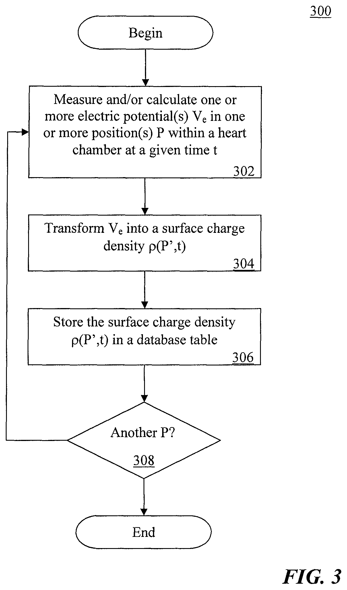
FIG. 3 is an example embodiment of a method of determining and storing surface charge densities, in accordance with aspects of the present invention; and
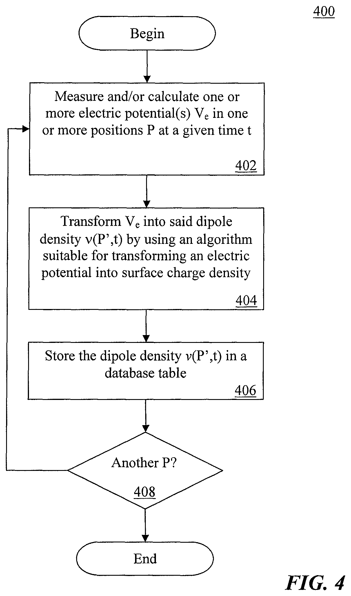
FIG. 4 is an example embodiment of a method of determining and storing dipole densities, in accordance with aspects of the present invention.
DETAILED DESCRIPTION OF ILLUSTRATIVE EMBODIMENTS
Research has indicated that the use of the surface charge densities (i.e. their distribution) or dipole densities (i.e. their distribution) to generate distribution map(s) will lead to a more detailed and precise information on electric ionic activity of local cardiac cells than potentials. Surface charge density or dipole densities represent a precise and sharp information of the electric activity with a good spatial resolution, whereas potentials resulting from integration of charge densities provide only a diffuse picture of electric activity. The electric nature of cardiac cell membranes comprising ionic charges of proteins and soluble ions can be precisely described by surface charge and dipole densities. The surface charge densities or dipole densities cannot be directly measured in the heart, but instead must be mathematically and accurately calculated starting from measured potentials. In other words, the information of voltage maps obtained by current mapping systems can be greatly refined when calculating surface charge densities or dipole densities from these.
The surface charge density means surface charge (Coulombs) per unit area (cm.sup.2). A dipole as such is a neutral element, wherein a part comprises a positive charge and the other part comprises the same but negative charge. A dipole might represent the electric nature of cellular membranes better, because in biological environment ion charges are not macroscopically separated.
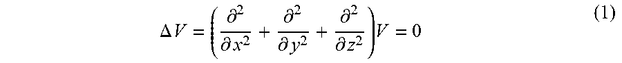
In order to generate a map of surface charge densities (surface charge density distribution) according to the present invention, the geometry of the given heart chamber must be known. The 3D geometry of the cardiac chamber is typically assessed by currently available and common mapping systems (so-called locator systems) or, alternatively, by integrating anatomical data from CT/MRI scans. FIG. 1 shows an example embodiment of a mapping system 100 that can be used to map a heart 12 of a human 10. Mapping system 100 can include a computer 110 having known types of input devices and output devices, such as a display 120 and printer 130, and a probe system 140. For the measurement of potentials the non-contact mapping method a probe electrode 142 will be used, which is connected to the computer 110 via a cable and forms part of probe system 140. The probe electrode 142 may be a multi-electrode array with elliptic or spherical shape. The spherical shape has certain advantages for the subsequent data analysis. But also other types or even several independent electrodes could be used to measure V.sub.e. For example, when considering, for example, the ventricular cavity within the endocardium and taking a probe electrode with a surface S.sub.P, which is located in the blood, it is possible to measure the potential V(x,y,z) at point x,y,z on the surface S.sub.P. In order to calculate the potential at the endocardial surface S.sub.e the Laplace equation:
.DELTA..times..times..differential..differential..differential..different- ial..differential..differential..times. ##EQU00003## needs to be solved, wherein V is the potential and x,y,z denote the three dimensional coordinates. The boundary conditions for this equation are V(x,y,z)=V.rho.(x,y,z) on S.sub.P, wherein V.sub.P is the potential on surface of the probe.
The solution is an integral that allows for calculating the potential V(x'y'z') at any point x'y'z' in the whole volume of the heart chamber that is filled with blood. For calculating said integral numerically a discretisation of the cardiac surface is necessary and the so called boundary element method (BEM) has to be used.
The boundary element method is a numerical computational method for solving linear integral equations (i.e. in surface integral form). The method is applied in many areas of engineering and science including fluid mechanics, acoustics, electromagnetics, and fracture mechanics.
The boundary element method is often more efficient than other methods, including the finite element method. Boundary element formulations typically give rise to fully populated matrices after discretisation. This means, that the storage requirements and computational time will tend to grow according to the square of the problem size. By contrast, finite element matrices are typically banded (elements are only locally connected) and the storage requirements for the system matrices typically grow quite linearly with the problem size.
With the above in mind, all potentials V.sub.P (x1',y1',z1') on the surface of the probe can be measured. To calculate the potential V.sub.e on the wall of the heart chamber, the known geometry of the surface of the heart chamber must be divided in discrete parts to use the boundary element method. The endocardial potentials V.sub.e are then given by a linear matrix transformation T from the probe potentials V.sub.P:V.sub.e=T V.sub.P.
After measuring and calculating one or more electric potential(s) V.sub.e of cardiac cells in one or more position(s) P(x,y,z) of the at least one given heart chamber at a given time t. The surface charge density and the dipole density is related to potential according to the following two Poisson equations:
.DELTA..times..times..rho..function..times..delta..function..DELTA..times- ..times..delta..differential..times..upsilon..delta..function. ##EQU00004## wherein .rho.(P) is the surface charge density in position P=x,y,z, .delta..sub.S.sub.e(P) is the delta-distribution concentrated on the surface of the heart chamber S.sub.e and .upsilon. is the dipole density.
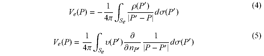
There is a well known relationship between the potential V.sub.e on the surface of the wall of the heart chamber and the surface charge (4) or dipole densities (5).
.function..times..pi..times..intg..times..rho..function.''.times..times..- times..sigma..function.'.function..times..pi..times..intg..times..upsilon.- .function.'.times..differential..differential.'.times.'.times..times..time- s..sigma..function.' ##EQU00005## (For a review see Jackson J D. Classical Electrodynamics, 2.sup.nd edition, Wiley, New York 1975.)
The boundary element method again provides a code for transforming the potential V.sub.e in formulas 4 and 5 into the desired surface charge densities and dipole densities, which can be recorded in the database.
In another embodiment of the method of the present invention the electric potential(s) V.sub.e is (are) determined by contact mapping. In this case the steps for calculating the electric potential V.sub.e are not necessary, because the direct contact of the electrode to the wall of the heart chamber already provides the electric potential V.sub.e.
In a preferred embodiment of the method of the present invention the probe electrode comprises a shape that allows for calculating precisely the electric potential V.sub.e and, thus, simplifies the calculations for transforming V.sub.e into the desired charge or dipole densities. This preferred geometry of the electrode is essentially ellipsoidal or spherical.
In order to employ the method for determining a database table of surface charge densities of at least one given heart chamber in the context of the present invention, it is preferred to use a system comprising at least: a) one unit for measuring and recording electric potentials V at a given position P(x,y,z) on the surface of a given heart chamber (Contact mapping) or a probe electrode positioned within the heart, but without direct wall contact (noncontact mapping) b) one a/d-converter for converting the measured electric potentials into digital data, c) one memory to save the measured and/or transformed data, and d) one processor unit for transforming the digital data into digital surface charge density or dipole density data.
It is noted that numerous devices for localising and determining electric potentials of cardiac cells in a given heart chamber by invasive and non-invasive methods are well known in the art and have been employed by medical practitioners over many years. Hence, the method, system, and devices of the present invention do not require any particular new electrodes for implementing the best mode for practicing the present invention. Instead, the invention provides a new and advantageous processing of the available data that will allow for an increase in precision, accuracy and spatial resolution of cardiac activation mapping when compared to prior art systems based on electric surface potentials in the heart only. In the near future, the present invention will allow for providing superior diagnostic means for diagnosing cardiac arrhythmias and electric status of heart cells including metabolic and functional information.
FIG. 2 provides an example embodiment of a computer architecture 200 that can form part of mapping system 100. Architecture 200 includes standard interface modules 210 for probe system 140 (and electrode 142) and standard interface modules 220 for interfacing with output devices 120, 130. The computer includes at least one processor 240 and at least one computer memory 250. The foregoing are generally known, however the present invention further includes an electrical potential to surface charge density and/or dipole density converter module 230. Module 230 includes instructions necessary for carrying out the methods described herein, when executed by processor 240, wherein the results of such processing are stored in memory 250--as would be understood by one skilled in the art having the benefit of this disclosure.
FIG. 3 and FIG. 4 summarize methods for determining and storing surface charge densities and dipole densities in accordance with aspects of the present invention, respectively, which have been described in detail above.
In method 300 of FIG. 3, in step 302, mapping system 100 is used to measure and/or calculate one or more electric potential(s) V.sub.e into one or more position(s) P within a heart chamber at a given time t. In step 304, V.sub.e is transformed into a surface charge density .rho.(P',t). In step 306, the surface charge density .rho.(P',t) is stored in a database table. The method is repeated if there is another P, in step 308.
In method 400 of FIG. 4, in step 402, mapping system 100 is used to measure and/or calculate one or more electric potential(s) V.sub.e in one or more position(s) P within a heart chamber at a given time t. In step 404, V.sub.e is transformed into said dipole density .nu.(P',t) by using an algorithm suitable for transforming an electric potential into surface charge density. In step 406, the dipole density .nu.(P',t) is stored in a database table. The method is repeated if there is another P, in step 408.
While the foregoing has described what are considered to be the best mode and/or other preferred embodiments, it is understood that various modifications may be made therein and that the invention or inventions may be implemented in various forms and embodiments, and that they may be applied in numerous applications, only some of which have been described herein. It is intended by the following claims to claim that which is literally described and all equivalents thereto, including all modifications and variations that fall within the scope of each claim.
* * * * *
References
D00000
D00001
D00002
D00003
D00004
M00001
M00002
M00003
M00004
M00005
M00006
M00007
XML
uspto.report is an independent third-party trademark research tool that is not affiliated, endorsed, or sponsored by the United States Patent and Trademark Office (USPTO) or any other governmental organization. The information provided by uspto.report is based on publicly available data at the time of writing and is intended for informational purposes only.
While we strive to provide accurate and up-to-date information, we do not guarantee the accuracy, completeness, reliability, or suitability of the information displayed on this site. The use of this site is at your own risk. Any reliance you place on such information is therefore strictly at your own risk.
All official trademark data, including owner information, should be verified by visiting the official USPTO website at www.uspto.gov. This site is not intended to replace professional legal advice and should not be used as a substitute for consulting with a legal professional who is knowledgeable about trademark law.