Policy-driven switch overlay bypass in a hybrid cloud network environment
Chang , et al. May 11, 2
U.S. patent number 11,005,682 [Application Number 14/876,627] was granted by the patent office on 2021-05-11 for policy-driven switch overlay bypass in a hybrid cloud network environment. This patent grant is currently assigned to CISCO TECHNOLOGY, INC.. The grantee listed for this patent is Cisco Technology, Inc.. Invention is credited to Nagaraj A. Bagepalli, David W. Chang, Dileep Kumar Devireddy, Abhijit Patra.


| United States Patent | 11,005,682 |
| Chang , et al. | May 11, 2021 |
Policy-driven switch overlay bypass in a hybrid cloud network environment
Abstract
Network policies can be used to optimize the flow of network traffic between virtual machines (VMs) in a hybrid cloud environment. In an example embodiment, one or more policies can drive a virtual switch controller, a hybrid cloud manager, a hypervisor manager, a virtual switch, or other orchestrator to create one or more direct tunnels that can be utilized by a respective pair of VMs to bypass the virtual switch and enable direct communication between the VMs. The virtual switch can send the VMs network and security policies to ensure that these policies are enforced. The VMs can exchange security credentials in order to establish the direct tunnel. The direct tunnel can be used by the VMs to bypass the virtual switch and allow the VMs to communicate with each other directly.
| Inventors: | Chang; David W. (Milpitas, CA), Patra; Abhijit (Saratoga, CA), Bagepalli; Nagaraj A. (Fremont, CA), Devireddy; Dileep Kumar (San Jose, CA) | ||||||||||
|---|---|---|---|---|---|---|---|---|---|---|---|
| Applicant: |
|
||||||||||
| Assignee: | CISCO TECHNOLOGY, INC. (San
Jose, CA) |
||||||||||
| Family ID: | 1000005546249 | ||||||||||
| Appl. No.: | 14/876,627 | ||||||||||
| Filed: | October 6, 2015 |
Prior Publication Data
| Document Identifier | Publication Date | |
|---|---|---|
| US 20170099188 A1 | Apr 6, 2017 | |
| Current U.S. Class: | 1/1 |
| Current CPC Class: | H04L 67/10 (20130101); H04L 63/20 (20130101); H04L 63/102 (20130101); H04L 12/4633 (20130101); H04L 61/6022 (20130101); H04L 41/0896 (20130101); H04L 61/103 (20130101); H04L 12/4641 (20130101) |
| Current International Class: | H04L 12/24 (20060101); H04L 29/08 (20060101); H04L 12/46 (20060101); H04L 29/06 (20060101); H04L 29/12 (20060101) |
| Field of Search: | ;709/223-229 ;370/30,254,360,392,419-422 |
References Cited [Referenced By]
U.S. Patent Documents
| 5812773 | September 1998 | Norin |
| 5889896 | March 1999 | Meshinsky et al. |
| 6108782 | August 2000 | Fletcher et al. |
| 6178453 | January 2001 | Mattaway et al. |
| 6298153 | October 2001 | Oishi |
| 6343290 | January 2002 | Cossins et al. |
| 6643260 | November 2003 | Kloth et al. |
| 6683873 | January 2004 | Kwok et al. |
| 6721804 | April 2004 | Rubin et al. |
| 6733449 | May 2004 | Krishnamurthy et al. |
| 6735631 | May 2004 | Oehrke et al. |
| 6885670 | April 2005 | Regula |
| 6996615 | February 2006 | McGuire |
| 7054930 | May 2006 | Cheriton |
| 7058706 | June 2006 | Lyer et al. |
| 7062571 | June 2006 | Dale et al. |
| 7076397 | July 2006 | Ding et al. |
| 7111177 | September 2006 | Chauvel et al. |
| 7212490 | May 2007 | Kao et al. |
| 7277948 | October 2007 | Igarashi et al. |
| 7313667 | December 2007 | Pullela et al. |
| 7379846 | May 2008 | Williams et al. |
| 7480672 | January 2009 | Hahn et al. |
| 7496043 | February 2009 | Leong et al. |
| 7536476 | May 2009 | Alleyne |
| 7567504 | July 2009 | Darling et al. |
| 7606147 | October 2009 | Luft et al. |
| 7647594 | January 2010 | Togawa |
| 7684322 | March 2010 | Sand et al. |
| 7773510 | August 2010 | Back et al. |
| 7808897 | October 2010 | Mehta et al. |
| 7881957 | February 2011 | Cohen et al. |
| 7917647 | March 2011 | Cooper et al. |
| 8010598 | August 2011 | Tanimoto |
| 8028071 | September 2011 | Mahalingam et al. |
| 8041714 | October 2011 | Aymeloglu et al. |
| 8121117 | February 2012 | Amdahl et al. |
| 8171415 | May 2012 | Appleyard et al. |
| 8234377 | July 2012 | Cohn |
| 8244559 | August 2012 | Horvitz et al. |
| 8250215 | August 2012 | Stienhans et al. |
| 8280880 | October 2012 | Aymeloglu et al. |
| 8284664 | October 2012 | Aybay et al. |
| 8284776 | October 2012 | Petersen |
| 8301746 | October 2012 | Head et al. |
| 8345692 | January 2013 | Smith |
| 8406141 | March 2013 | Couturier et al. |
| 8407413 | March 2013 | Yucel et al. |
| 8448171 | May 2013 | Donnellan et al. |
| 8477610 | July 2013 | Zuo et al. |
| 8495252 | July 2013 | Lais et al. |
| 8495356 | July 2013 | Ashok et al. |
| 8510469 | August 2013 | Portolani |
| 8514868 | August 2013 | Hill |
| 8532108 | September 2013 | Li et al. |
| 8533687 | September 2013 | Greifeneder et al. |
| 8547974 | October 2013 | Guruswamy et al. |
| 8560639 | October 2013 | Murphy et al. |
| 8560663 | October 2013 | Baucke et al. |
| 8589543 | November 2013 | Dutta et al. |
| 8590050 | November 2013 | Nagpal et al. |
| 8611356 | December 2013 | Yu et al. |
| 8612625 | December 2013 | Andries et al. |
| 8630291 | January 2014 | Shaffer et al. |
| 8639787 | January 2014 | Lagergren et al. |
| 8656024 | February 2014 | Krishnan et al. |
| 8660129 | February 2014 | Brendel et al. |
| 8719804 | May 2014 | Jain |
| 8775576 | July 2014 | Hebert et al. |
| 8797867 | August 2014 | Chen et al. |
| 8805951 | August 2014 | Faibish et al. |
| 8850182 | September 2014 | Fritz et al. |
| 8856339 | October 2014 | Mestery et al. |
| 8909780 | December 2014 | Dickinson |
| 8909928 | December 2014 | Ahmad et al. |
| 8918510 | December 2014 | Gmach et al. |
| 8924720 | December 2014 | Raghuram et al. |
| 8930747 | January 2015 | Levijarvi et al. |
| 8938775 | January 2015 | Roth et al. |
| 8959526 | February 2015 | Kansal et al. |
| 8977754 | March 2015 | Curry, Jr. et al. |
| 9009697 | April 2015 | Breiter et al. |
| 9015324 | April 2015 | Jackson |
| 9043439 | May 2015 | Bicket et al. |
| 9049115 | June 2015 | Rajendran et al. |
| 9063789 | June 2015 | Beaty et al. |
| 9065727 | June 2015 | Liu et al. |
| 9075649 | July 2015 | Bushman et al. |
| 9104334 | August 2015 | Madhusudana et al. |
| 9164795 | October 2015 | Vincent |
| 9167050 | October 2015 | Durazzo et al. |
| 9201701 | December 2015 | Boldyrev et al. |
| 9201704 | December 2015 | Chang et al. |
| 9203784 | December 2015 | Chang et al. |
| 9223634 | December 2015 | Chang et al. |
| 9244776 | January 2016 | Koza et al. |
| 9251114 | February 2016 | Ancin et al. |
| 9264478 | February 2016 | Hon et al. |
| 9313048 | April 2016 | Chang et al. |
| 9361192 | June 2016 | Smith et al. |
| 9380075 | June 2016 | He et al. |
| 9432294 | August 2016 | Sharma et al. |
| 9444744 | September 2016 | Sharma et al. |
| 9473365 | October 2016 | Melander et al. |
| 9503530 | November 2016 | Niedzielski |
| 9558078 | January 2017 | Farlee et al. |
| 9613078 | April 2017 | Vermeulen et al. |
| 9628471 | April 2017 | Sundaram et al. |
| 9632858 | April 2017 | Sasturkar et al. |
| 9658876 | May 2017 | Chang et al. |
| 9692802 | June 2017 | Bicket et al. |
| 9727359 | August 2017 | Tsirkin |
| 9736063 | August 2017 | Wan et al. |
| 9755858 | September 2017 | Bagepalli et al. |
| 9792245 | October 2017 | Raghavan et al. |
| 9804988 | October 2017 | Ayoub et al. |
| 9954783 | April 2018 | Thirumurthi et al. |
| 2002/0004900 | January 2002 | Patel |
| 2002/0073337 | June 2002 | Ioele et al. |
| 2002/0143928 | October 2002 | Maltz et al. |
| 2002/0166117 | November 2002 | Abrams et al. |
| 2002/0174216 | November 2002 | Shorey et al. |
| 2003/0018591 | January 2003 | Komisky |
| 2003/0056001 | March 2003 | Mate et al. |
| 2003/0228585 | December 2003 | Inoko et al. |
| 2004/0004941 | January 2004 | Malan et al. |
| 2004/0095237 | May 2004 | Chen et al. |
| 2004/0131059 | July 2004 | Ayyakad et al. |
| 2004/0264481 | December 2004 | Darling et al. |
| 2005/0060418 | March 2005 | Sorokopud |
| 2005/0125424 | June 2005 | Herriott et al. |
| 2006/0059558 | March 2006 | Selep et al. |
| 2006/0104286 | May 2006 | Cheriton |
| 2006/0120575 | June 2006 | Ahn et al. |
| 2006/0126665 | June 2006 | Ward et al. |
| 2006/0146825 | July 2006 | Hofstaedter et al. |
| 2006/0155875 | July 2006 | Cheriton |
| 2006/0168338 | July 2006 | Bruegl et al. |
| 2006/0294207 | December 2006 | Barsness et al. |
| 2007/0011330 | January 2007 | Dinker et al. |
| 2007/0174663 | July 2007 | Crawford et al. |
| 2007/0223487 | September 2007 | Kajekar et al. |
| 2007/0242830 | October 2007 | Conrado et al. |
| 2008/0005293 | January 2008 | Bhargava et al. |
| 2008/0084880 | April 2008 | Dharwadkar |
| 2008/0165778 | July 2008 | Ertemalp |
| 2008/0198752 | August 2008 | Fan et al. |
| 2008/0201711 | August 2008 | Amir Husain |
| 2008/0235755 | September 2008 | Blaisdell et al. |
| 2009/0006527 | January 2009 | Gingell, Jr. et al. |
| 2009/0010277 | January 2009 | Halbraich et al. |
| 2009/0019367 | January 2009 | Cavagnari et al. |
| 2009/0031312 | January 2009 | Mausolf et al. |
| 2009/0083183 | March 2009 | Rao et al. |
| 2009/0138763 | May 2009 | Arnold |
| 2009/0177775 | July 2009 | Radia et al. |
| 2009/0178058 | July 2009 | Stillwell, III et al. |
| 2009/0182874 | July 2009 | Morford et al. |
| 2009/0265468 | October 2009 | Annambhotla et al. |
| 2009/0265753 | October 2009 | Anderson et al. |
| 2009/0293056 | November 2009 | Ferris |
| 2009/0300608 | December 2009 | Ferris et al. |
| 2009/0313562 | December 2009 | Appleyard et al. |
| 2009/0323706 | December 2009 | Germain et al. |
| 2009/0328031 | December 2009 | Pouyadou et al. |
| 2010/0042720 | February 2010 | Stienhans et al. |
| 2010/0061250 | March 2010 | Nugent |
| 2010/0115341 | May 2010 | Baker et al. |
| 2010/0131765 | May 2010 | Bromley et al. |
| 2010/0191783 | July 2010 | Mason et al. |
| 2010/0192157 | July 2010 | Jackson et al. |
| 2010/0205601 | August 2010 | Abbas et al. |
| 2010/0211782 | August 2010 | Auradkar et al. |
| 2010/0217886 | August 2010 | Seren et al. |
| 2010/0293270 | November 2010 | Augenstein et al. |
| 2010/0318609 | December 2010 | Lahiri et al. |
| 2010/0325199 | December 2010 | Park et al. |
| 2010/0325257 | December 2010 | Goel et al. |
| 2010/0325441 | December 2010 | Laurie et al. |
| 2010/0333116 | December 2010 | Prahlad et al. |
| 2011/0016214 | January 2011 | Jackson |
| 2011/0035754 | February 2011 | Srinivasan |
| 2011/0055396 | March 2011 | Dehaan |
| 2011/0055398 | March 2011 | Dehaan et al. |
| 2011/0055470 | March 2011 | Portolani |
| 2011/0072489 | March 2011 | Parann-Nissany |
| 2011/0075667 | March 2011 | Li et al. |
| 2011/0110382 | May 2011 | Jabr et al. |
| 2011/0116443 | May 2011 | Yu et al. |
| 2011/0126099 | May 2011 | Anderson et al. |
| 2011/0138055 | June 2011 | Daly et al. |
| 2011/0145413 | June 2011 | Dawson et al. |
| 2011/0145657 | June 2011 | Bishop et al. |
| 2011/0173303 | July 2011 | Rider |
| 2011/0185063 | July 2011 | Head et al. |
| 2011/0199902 | August 2011 | Leavy et al. |
| 2011/0213687 | September 2011 | Ferris et al. |
| 2011/0213966 | September 2011 | Fu et al. |
| 2011/0219434 | September 2011 | Betz et al. |
| 2011/0231715 | September 2011 | Kunii et al. |
| 2011/0231899 | September 2011 | Pulier et al. |
| 2011/0239039 | September 2011 | Dieffenbach et al. |
| 2011/0252327 | October 2011 | Awasthi et al. |
| 2011/0261811 | October 2011 | Battestilli et al. |
| 2011/0261828 | October 2011 | Smith |
| 2011/0276675 | November 2011 | Singh et al. |
| 2011/0276951 | November 2011 | Jain |
| 2011/0295998 | December 2011 | Ferris et al. |
| 2011/0305149 | December 2011 | Scott et al. |
| 2011/0307531 | December 2011 | Gaponenko et al. |
| 2011/0320870 | December 2011 | Kenigsberg et al. |
| 2012/0005724 | January 2012 | Lee |
| 2012/0023418 | January 2012 | Frields et al. |
| 2012/0054367 | March 2012 | Ramakrishnan et al. |
| 2012/0072318 | March 2012 | Akiyama et al. |
| 2012/0072578 | March 2012 | Alam |
| 2012/0072581 | March 2012 | Tung et al. |
| 2012/0072985 | March 2012 | Davne et al. |
| 2012/0072992 | March 2012 | Arasaratnam et al. |
| 2012/0084445 | April 2012 | Brock et al. |
| 2012/0084782 | April 2012 | Chou et al. |
| 2012/0096134 | April 2012 | Suit |
| 2012/0102193 | April 2012 | Rathore et al. |
| 2012/0102199 | April 2012 | Hopmann et al. |
| 2012/0131174 | May 2012 | Ferris et al. |
| 2012/0137215 | May 2012 | Kawara |
| 2012/0158967 | June 2012 | Sedayao et al. |
| 2012/0159097 | June 2012 | Jennas, II et al. |
| 2012/0166649 | June 2012 | Watanabe et al. |
| 2012/0167094 | June 2012 | Suit |
| 2012/0173541 | July 2012 | Venkataramani |
| 2012/0173710 | July 2012 | Rodriguez |
| 2012/0179909 | July 2012 | Sagi et al. |
| 2012/0180044 | July 2012 | Donnellan et al. |
| 2012/0182891 | July 2012 | Lee et al. |
| 2012/0185632 | July 2012 | Lais et al. |
| 2012/0185913 | July 2012 | Martinez et al. |
| 2012/0192016 | July 2012 | Gotesdyner et al. |
| 2012/0192075 | July 2012 | Ebtekar et al. |
| 2012/0201135 | August 2012 | Ding et al. |
| 2012/0203908 | August 2012 | Beaty et al. |
| 2012/0204169 | August 2012 | Breiter et al. |
| 2012/0204187 | August 2012 | Breiter et al. |
| 2012/0214506 | August 2012 | Skaaksrud et al. |
| 2012/0222106 | August 2012 | Kuehl |
| 2012/0236716 | September 2012 | Anbazhagan et al. |
| 2012/0240113 | September 2012 | Hur |
| 2012/0265976 | October 2012 | Spiers et al. |
| 2012/0272025 | October 2012 | Park et al. |
| 2012/0281706 | November 2012 | Agarwal et al. |
| 2012/0281708 | November 2012 | Chauhan et al. |
| 2012/0290647 | November 2012 | Ellison et al. |
| 2012/0297238 | November 2012 | Watson et al. |
| 2012/0311106 | December 2012 | Morgan |
| 2012/0311568 | December 2012 | Jansen |
| 2012/0324092 | December 2012 | Brown et al. |
| 2012/0324114 | December 2012 | Dutta et al. |
| 2013/0003567 | January 2013 | Gallant et al. |
| 2013/0013248 | January 2013 | Brugler et al. |
| 2013/0036213 | February 2013 | Hasan et al. |
| 2013/0044636 | February 2013 | Koponen et al. |
| 2013/0066940 | March 2013 | Shao |
| 2013/0069950 | March 2013 | Adam et al. |
| 2013/0080509 | March 2013 | Wang |
| 2013/0080624 | March 2013 | Nagai et al. |
| 2013/0091557 | April 2013 | Gurrapu |
| 2013/0097601 | April 2013 | Podvratnik et al. |
| 2013/0104140 | April 2013 | Meng et al. |
| 2013/0111540 | May 2013 | Sabin |
| 2013/0117337 | May 2013 | Dunham |
| 2013/0124712 | May 2013 | Parker |
| 2013/0125124 | May 2013 | Kempf et al. |
| 2013/0138816 | May 2013 | Kuo et al. |
| 2013/0144978 | June 2013 | Jain et al. |
| 2013/0152076 | June 2013 | Patel |
| 2013/0152175 | June 2013 | Hromoko et al. |
| 2013/0159097 | June 2013 | Schory et al. |
| 2013/0159496 | June 2013 | Hamilton et al. |
| 2013/0160008 | June 2013 | Cawlfield et al. |
| 2013/0162753 | June 2013 | Hendrickson et al. |
| 2013/0169666 | July 2013 | Pacheco et al. |
| 2013/0179941 | July 2013 | McGloin et al. |
| 2013/0182712 | July 2013 | Aguayo et al. |
| 2013/0185413 | July 2013 | Beaty et al. |
| 2013/0185433 | July 2013 | Zhu et al. |
| 2013/0191106 | July 2013 | Kephart et al. |
| 2013/0198050 | August 2013 | Shroff et al. |
| 2013/0198374 | August 2013 | Zalmanovitch et al. |
| 2013/0204849 | August 2013 | Chacko |
| 2013/0232491 | September 2013 | Radhakrishnan |
| 2013/0232492 | September 2013 | Wang |
| 2013/0246588 | September 2013 | Borowicz et al. |
| 2013/0250770 | September 2013 | Zou et al. |
| 2013/0254415 | September 2013 | Fullen et al. |
| 2013/0262347 | October 2013 | Dodson |
| 2013/0268643 | October 2013 | Chang |
| 2013/0283364 | October 2013 | Chang et al. |
| 2013/0297769 | November 2013 | Chang et al. |
| 2013/0318240 | November 2013 | Hebert et al. |
| 2013/0318546 | November 2013 | Kothuri et al. |
| 2013/0339949 | December 2013 | Spiers et al. |
| 2014/0006481 | January 2014 | Frey et al. |
| 2014/0006535 | January 2014 | Reddy |
| 2014/0006585 | January 2014 | Dunbar et al. |
| 2014/0019639 | January 2014 | Ueno |
| 2014/0040473 | February 2014 | Ho et al. |
| 2014/0040883 | February 2014 | Tompkins |
| 2014/0052877 | February 2014 | Mao |
| 2014/0059310 | February 2014 | Du et al. |
| 2014/0074850 | March 2014 | Noel et al. |
| 2014/0075048 | March 2014 | Yuksel et al. |
| 2014/0075108 | March 2014 | Dong et al. |
| 2014/0075357 | March 2014 | Flores et al. |
| 2014/0075501 | March 2014 | Srinivasan et al. |
| 2014/0089727 | March 2014 | Cherkasova et al. |
| 2014/0098762 | April 2014 | Ghai et al. |
| 2014/0108985 | April 2014 | Scott et al. |
| 2014/0122560 | May 2014 | Ramey et al. |
| 2014/0136779 | May 2014 | Guha et al. |
| 2014/0140211 | May 2014 | Chandrasekaran et al. |
| 2014/0141720 | May 2014 | Princen et al. |
| 2014/0156557 | June 2014 | Zeng et al. |
| 2014/0160924 | June 2014 | Pfautz et al. |
| 2014/0164486 | June 2014 | Ravichandran et al. |
| 2014/0188825 | July 2014 | Muthukkaruppan et al. |
| 2014/0189095 | July 2014 | Lindberg et al. |
| 2014/0189125 | July 2014 | Amies et al. |
| 2014/0215471 | July 2014 | Cherkasova |
| 2014/0222953 | August 2014 | Karve et al. |
| 2014/0244851 | August 2014 | Lee |
| 2014/0245298 | August 2014 | Zhou et al. |
| 2014/0269266 | September 2014 | Filsfils et al. |
| 2014/0280805 | September 2014 | Sawalha |
| 2014/0282536 | September 2014 | Dave et al. |
| 2014/0282611 | September 2014 | Campbell et al. |
| 2014/0282669 | September 2014 | McMillan |
| 2014/0282889 | September 2014 | Ishaya et al. |
| 2014/0289200 | September 2014 | Kato |
| 2014/0297569 | October 2014 | Clark et al. |
| 2014/0297835 | October 2014 | Buys |
| 2014/0314078 | October 2014 | Jilani |
| 2014/0317261 | October 2014 | Shatzkamer et al. |
| 2014/0366155 | December 2014 | Chang et al. |
| 2014/0372567 | December 2014 | Ganesh et al. |
| 2015/0006470 | January 2015 | Mohan |
| 2015/0033086 | January 2015 | Sasturkar et al. |
| 2015/0043335 | February 2015 | Testicioglu et al. |
| 2015/0043576 | February 2015 | Dixon et al. |
| 2015/0052247 | February 2015 | Threefoot et al. |
| 2015/0052517 | February 2015 | Raghu et al. |
| 2015/0058382 | February 2015 | St. Laurent et al. |
| 2015/0058459 | February 2015 | Amendjian et al. |
| 2015/0058557 | February 2015 | Madhusudana et al. |
| 2015/0063102 | March 2015 | Mestery |
| 2015/0070516 | March 2015 | Shoemake et al. |
| 2015/0071285 | March 2015 | Kumar et al. |
| 2015/0089478 | March 2015 | Cheluvaraju et al. |
| 2015/0100471 | April 2015 | Curry, Jr. et al. |
| 2015/0106802 | April 2015 | Ivanov et al. |
| 2015/0106805 | April 2015 | Melander et al. |
| 2015/0109923 | April 2015 | Hwang |
| 2015/0117199 | April 2015 | Chinnaiah Sankaran et al. |
| 2015/0117458 | April 2015 | Gurkan et al. |
| 2015/0120914 | April 2015 | Wada et al. |
| 2015/0149828 | May 2015 | Mukerji et al. |
| 2015/0178133 | June 2015 | Phelan et al. |
| 2015/0215819 | July 2015 | Bosch et al. |
| 2015/0227405 | August 2015 | Jan et al. |
| 2015/0242204 | August 2015 | Hassine et al. |
| 2015/0249709 | September 2015 | Teng et al. |
| 2015/0271199 | September 2015 | Bradley et al. |
| 2015/0280980 | October 2015 | Bitar |
| 2015/0281067 | October 2015 | Wu |
| 2015/0281113 | October 2015 | Siciliano et al. |
| 2015/0309908 | October 2015 | Pearson et al. |
| 2015/0319063 | November 2015 | Zourzouvillys et al. |
| 2015/0326524 | November 2015 | Tankala et al. |
| 2015/0339210 | November 2015 | Kopp et al. |
| 2015/0373108 | December 2015 | Fleming et al. |
| 2015/0379062 | December 2015 | Vermeulen et al. |
| 2016/0011925 | January 2016 | Kulkarni et al. |
| 2016/0013990 | January 2016 | Kulkarni et al. |
| 2016/0062786 | March 2016 | Meng et al. |
| 2016/0065417 | March 2016 | Sapuram et al. |
| 2016/0094398 | March 2016 | Choudhury et al. |
| 2016/0094480 | March 2016 | Kulkarni et al. |
| 2016/0094643 | March 2016 | Jain et al. |
| 2016/0094894 | March 2016 | Inayatullah et al. |
| 2016/0099847 | April 2016 | Melander et al. |
| 2016/0099873 | April 2016 | Gero et al. |
| 2016/0103838 | April 2016 | Sainani et al. |
| 2016/0105393 | April 2016 | Thakkar et al. |
| 2016/0127184 | May 2016 | Bursell |
| 2016/0134557 | May 2016 | Steinder et al. |
| 2016/0147676 | May 2016 | Cha et al. |
| 2016/0162436 | June 2016 | Raghavan et al. |
| 2016/0164914 | June 2016 | Madhav et al. |
| 2016/0188527 | June 2016 | Cherian |
| 2016/0234071 | August 2016 | Nambiar et al. |
| 2016/0239399 | August 2016 | Babu et al. |
| 2016/0253078 | September 2016 | Ebtekar et al. |
| 2016/0254968 | September 2016 | Ebtekar et al. |
| 2016/0261564 | September 2016 | Foxhoven et al. |
| 2016/0277368 | September 2016 | Narayanaswamy et al. |
| 2016/0292611 | October 2016 | Boe et al. |
| 2016/0352682 | December 2016 | Chang |
| 2016/0378389 | December 2016 | Hrischuk et al. |
| 2017/0005948 | January 2017 | Melander et al. |
| 2017/0024260 | January 2017 | Chandrasekaran et al. |
| 2017/0026470 | January 2017 | Bhargava et al. |
| 2017/0034199 | February 2017 | Zaw |
| 2017/0041342 | February 2017 | Efremov et al. |
| 2017/0054659 | February 2017 | Ergin |
| 2017/0063674 | March 2017 | Maskalik et al. |
| 2017/0097841 | April 2017 | Chang et al. |
| 2017/0104755 | April 2017 | Arregoces et al. |
| 2017/0126583 | May 2017 | Xia |
| 2017/0147297 | May 2017 | Krishnamurthy et al. |
| 2017/0163569 | June 2017 | Koganti |
| 2017/0171158 | June 2017 | Hoy et al. |
| 2017/0192823 | July 2017 | Karaje et al. |
| 2017/0264663 | September 2017 | Bicket et al. |
| 2017/0302521 | October 2017 | Lui et al. |
| 2017/0310556 | October 2017 | Knowles et al. |
| 2017/0317932 | November 2017 | Paramasivam |
| 2017/0339070 | November 2017 | Chang et al. |
| 2018/0069885 | March 2018 | Patterson et al. |
| 2018/0173372 | June 2018 | Greenspan et al. |
| 2018/0174060 | June 2018 | Velez-Rojas et al. |
| 101719930 | Jun 2010 | CN | |||
| 101394360 | Jul 2011 | CN | |||
| 102164091 | Aug 2011 | CN | |||
| 104320342 | Jan 2015 | CN | |||
| 105740084 | Jul 2016 | CN | |||
| 2228719 | Sep 2010 | EP | |||
| 2439637 | Apr 2012 | EP | |||
| 2645253 | Nov 2014 | EP | |||
| 10-2015-0070676 | May 2015 | KR | |||
| 394537 | Dec 2010 | TW | |||
| WO 2009/155574 | Dec 2009 | WO | |||
| WO 2010/030915 | Mar 2010 | WO | |||
| WO 2013/158707 | Oct 2013 | WO | |||
Other References
|
Cisco Systems, Inc., "Cisco Intercloud Fabric: Hybrid Cloud with Choice, Consistency, Control and Compliance," Dec. 10, 2014. cited by applicant . Author Unknown, "5 Benefits of a Storage Gateway in the Cloud," Blog, TwinStrata, Inc., Jul. 25, 2012, XP055141645, 4 pages, https://web.archive.org/web/20120725092619/http://blog.twinstrata.com/201- 2/07/101/5-benefits-of-a-storage-gateway-in-the-cloud. cited by applicant . Author Unknown, "Joint Cisco and VMWare Solution for Optimizing Virtual Desktop Delivery: Data Center 3.0: Solutions to Accelerate Data Center Virtualization," Cisco Systems, Inc. and VMware, Inc., Sep. 2008, 10 pages. cited by applicant . Author Unknown, "Open Data Center Alliance Usage: Virtual Machine (VM) Interoperability in a Hybrid Cloud Environment Rev. 1.2," Open Data Center Alliance, Inc., 2013, 18 pages. cited by applicant . Author Unknown, "Real-Time Performance Monitoring on Juniper Networks Devices, Tips and Tools for Assessing and Analyzing Network Efficiency," Juniper Networks, Inc., May 2010, 35 pages. cited by applicant . Beyer, Steffen, "Module "Data::Locations?!"," Yapc::Europe, London, UK,ICA, Sep. 22-24, 2000, XP002742700, 15 pages. cited by applicant . Borovick, Lucinda, et al., "Architecting the Network for the Cloud," IDC White Paper, Jan. 2011, 8 pages. cited by applicant . Bosch, Greg, "Virtualization," last modified Apr. 2012 by B. Davison, 33 pages. cited by applicant . Broadcasters Audience Research Board, "What's Next," http://Iwww.barb.co.uk/whats-next, accessed Jul. 22, 2015, 2 pages. cited by applicant . Cisco Systems, Inc. "Best Practices in Deploying Cisco Nexus 1000V Series Switches on Cisco UCS B and C Series Cisco UCS Manager Servers," Cisco White Paper, Apr. 2011, 36 pages, http://www.cisco.com/en/US/prod/collateral/switches/ps9441/ps9902/white_p- aper_c11-558242.pdf. cited by applicant . Cisco Systems, Inc., "Cisco Unified Network Services: Overcome Obstacles to Cloud-Ready Deployments," Cisco White Paper, Jan. 2011, 6 pages. cited by applicant . Cisco Technology, Inc., "Cisco Expands Videoscape TV Platform Into the Cloud," Jan. 6, 2014, Las Vegas, Nevada, Press Release, 3 pages. cited by applicant . CSS Corp, "Enterprise Cloud Gateway (ECG)--Policy driven framework for managing multi-cloud environments," original published on or about Feb. 11, 2012; 1 page; http://www.css-cloud.com/platform/enterprise-cloud-gateway.php. cited by applicant . Fang K., "LISP MAC-EID-TO-RLOC Mapping (LISP based L2VPN)," Network Working Group, Internet Draft, Cisco Systems, Jan. 2012, 12 pages. cited by applicant . Herry, William, "Keep It Simple, Stupid: OpenStack nova-scheduler and its algorithm", May 12, 2012, IBM, 12 pages. cited by applicant . Hewlett-Packard Company, "Virtual context management on network devices", Research Disclosure, vol. 564, No. 60, Apr. 1, 2011, Mason Publications, Hampshire, GB, Apr. 1, 2011, 524. cited by applicant . Juniper Networks, Inc., "Recreating Real Application Traffic in Junosphere Lab," Solution Brief, Dec. 2011, 3 pages. cited by applicant . Kenhui, "Musings on Cloud Computing and IT-as-a-Service: [Updated for Havana] Openstack Computer for VSphere Admins, Part 2: Nova-Scheduler and DRS", Jun. 26, 2013, Cloud Architect Musings, 12 pages. cited by applicant . Kolyshkin, Kirill, "Virtualization in Linux," Sep. 1, 2006, XP055141648, 5 pages, https://web.archive.org/web/20070120205111/http://download.openvz.- org/doc/openvz-intro.pdf. cited by applicant . Lerach, S.R.O., "Golem," http://www.lerach.cz/en/products/golem, accessed Jul. 22, 2015, 2 pages. cited by applicant . Linthicum, David, "VM Import could be a game changer for hybrid clouds", InfoWorld, Dec. 23, 2010, 4 pages. cited by applicant . Naik, Vijay K., et al., "Harmony: A Desktop Grid for Delivering Enterprise Computations," Grid Computing, 2003, Fourth International Workshop on Proceedings, Nov 17, 2003, pp. 1-11. cited by applicant . Nair, Srijith K. et al., "Towards Secure Cloud Bursting, Brokerage and Aggregation," 2012, 8 pages, www.flexiant.com. cited by applicant . Nielsen, "SimMetry Audience Measurement--Technology," http://www.nielsen-admosphere.eu/products-and-services/simmetry-audience-- measurement-technology/, accessed Jul. 22, 2015, 6 pages. cited by applicant . Nielsen, "Television," http://www.nielsen.com/us/en/solutions/measurement/television.html, accessed Jul. 22, 2015, 4 pages. cited by applicant . Open Stack, "Filter Scheduler," updated Dec. 17, 2017, 5 pages, accessed on Dec. 18, 2017, https://docs.openstack.org/nova/latest/user/filter-scheduler.html. cited by applicant . Rabadan, J., et al., "Operational Aspects of Proxy-ARP/ND in EVPN Networks," BESS Worksgroup Internet Draft, draft-snr-bess-evpn-proxy-arp-nd-02, Oct. 6, 2015, 22 pages. cited by applicant . Saidi, Ali, et al., "Performance Validation of Network-Intensive Workloads on a Full-System Simulator," Interaction between Operating System and Computer Architecture Workshop, (IOSCA 2005), Austin, Texas, Oct. 2005, 10 pages. cited by applicant . Shunra, "Shunra for HP Software; Enabling Confidence in Application Performance Before Deployment," 2010, 2 pages. cited by applicant . Son, Jungmin, "Automatic decision system for efficient resource selection and allocation in inter-clouds," Jun. 2013, 35 pages. cited by applicant . Wikipedia, "Filter (software)", Wikipedia, Feb. 8, 2014, 2 pages, https://en.wikipedia.orq/w/index.php?title=Filter_%28software%29&oldid=59- 4544359. cited by applicant . Wikipedia; "Pipeline (Unix)", Wikipedia, May 4, 2014, 4 pages, https://en.wikipedia.ord/w/index.php?title=Pipeline2/028Unix%29&oldid=606- 980114. cited by applicant . Amedro, Brian, et al., "An Efficient Framework for Running Applications on Clusters, Grids and Cloud," 2010, 17 pages. cited by applicant . Author Unknown, "A Look at DeltaCloud: The Multi-Cloud API," Feb. 17, 2012, 4 pages. cited by applicant . Author Unknown, "About Deltacloud," Apache Software Foundation, Aug. 18, 2013, 1 page. cited by applicant . Author Unknown, "Architecture for Managing Clouds, A White Paper from the Open Cloud Standards Incubator," Version 1.0.0, Document No. DSP-IS0102, Jun. 18, 2010, 57 pages. cited by applicant . Author Unknown, "Cloud Infrastructure Management Interface--Common Information Model (CIMI-CIM)," Document No. DSP0264, Version 1.0.0, Dec. 14, 2012, 21 pages. cited by applicant . Author Unknown, "Cloud Infrastructure Management Interface (CIMI) Primer," Document No. DSP2027, Version 1.0.1, Sep. 12, 2012, 30 pages. cited by applicant . Author Unknown, "cloudControl Documentation," Aug. 25, 2013, 14 pages. cited by applicant . Author Unknown, "Interoperable Clouds, A White Paper from the Open Cloud Standards Incubator," Version 1.0.0, Document No. DSP-IS0101, Nov. 11, 2009, 21 pages. cited by applicant . Author Unknown, "Microsoft Cloud Edge Gateway (MCE) Series Appliance," Iron Networks, Inc., 2014, 4 pages. cited by applicant . Author Unknown, "Use Cases and Interactions for Managing Clouds, A White Paper from the Open Cloud Standards Incubator," Version 1.0.0, Document No. DSP-ISO0103, Jun. 16, 2010, 75 pages. cited by applicant . Author Unknown, "Apache Ambari Meetup What's New," Hortonworks Inc., Sep. 2013, 28 pages. cited by applicant . Author Unknown, "Introduction," Apache Ambari project, Apache Software Foundation, 2014, 1 page. cited by applicant . CITRIX, "Citrix StoreFront 2.0" White Paper, Proof of Concept Implementation Guide, Citrix Systems, Inc., 2013, 48 pages. cited by applicant . Citrix, "CloudBridge for Microsoft Azure Deployment Guide," 30 pages. cited by applicant . Citrix, "Deployment Practices and Guidelines for NetScaler 10.5 on Amazon Web Services," White Paper, citrix.com, 2014, 14 pages. cited by applicant . Gedymin, Adam, "Cloud Computing with an emphasis on Google App Engine," Sep. 2011, 146 pages. cited by applicant . Good, Nathan A., "Use Apache Deltacloud to administer multiple instances with a single API," Dec. 17, 2012, 7 pages. cited by applicant . Kunz, Thomas, et al., "OmniCloud--The Secure and Flexible Use of Cloud Storage Services," 2014, 30 pages. cited by applicant . Logan, Marcus, "Hybrid Cloud Application Architecture for Elastic Java-Based Web Applications," F5 Deployment Guide Version 1.1, 2016, 65 pages. cited by applicant . Lynch, Sean, "Monitoring cache with Claspin" Facebook Engineering, Sep. 19, 2012, 5 pages. cited by applicant . Meireles, Fernando Miguel Dias, "Integrated Management of Cloud Computing Resources," 2013-2014, 286 pages. cited by applicant . Mu, Shuai, et al., "uLibCloud: Providing High Available and Uniform Accessing to Multiple Cloud Storages," 2012 IEEE, 8 pages. cited by applicant . Sun, Aobing, et al., "laaS Public Cloud Computing Platform Scheduling Model and Optimization Analysis," Int. J. Communications, Network and System Sciences, 2011, 4, 803-811, 9 pages. cited by applicant . Szymaniak, Michal, et al., "Latency-Driven Replica Placement", vol. 47 No. 8, IPSJ Journal, Aug. 2006, 12 pages. cited by applicant . Toews, Everett, "Introduction to Apache jclouds," Apr. 7, 2014, 23 pages. cited by applicant . Von Laszewski, Gregor, et al., "Design of a Dynamic Provisioning System for a Federated Cloud and Bare-metal Environment," 2012, 8 pages. cited by applicant . Ye, Xianglong, et al., "A Novel Blocks Placement Strategy for Hadoop," 2012 IEEE/ACTS 11.sup.th International Conference on Computer and Information Science, 2012 IEEE, 5 pages. cited by applicant . Al-Harbi, S.H., et al., "Adapting .kappa.-means for supervised clustering," Jun. 2006, Applied Intelligence, vol. 24, Issue 3, pp. 219- 226. cited by applicant . Bohner, Shawn A., "Extending Software Change Impact Analysis into COTS Components," 2003, IEEE, 8 pages. cited by applicant . Hood, C. S., et al., "Automated Proactive Anomaly Detection," 1997, Springer Science and Business Media Dordrecht , pp. 688-699. cited by applicant . Vilalta R., et al., "An efficient approach to external cluster assessment with an application to martian topography," Feb. 2007, 23 pages, Data Mining and Knowledge Discovery 14.1: 1-23. New York: Springer Science & Business Media. cited by applicant. |
Primary Examiner: Naji; Younes
Assistant Examiner: Ton; Da T
Attorney, Agent or Firm: Polsinelli PC
Claims
What is claimed is:
1. A method comprising: receiving, by a first virtual machine from a virtual switch via a secure access tunnel that includes a hop over the virtual switch, configuration information for establishing a second virtual machine as a second endpoint of a direct tunnel without the hop over the virtual switch, wherein the configuration information includes second security information of the second virtual machine, the virtual switch is a public cloud network gateway, and the first virtual machine is configured by the public cloud network gateway with a default rule to cause the first virtual machine to initially default to the secure access tunnel with the hop over the public cloud network gateway during initial deployment of the first virtual machine; sending, from the first virtual machine to the second virtual machine, a request to connect to the second virtual machine via the direct tunnel, wherein the request includes first security information of the first virtual machine and first authentication information of the first virtual machine derived from the second security information; receiving, by the first virtual machine from the second virtual machine, a reply that includes second authentication information of the second virtual machine derived from the first security information; establishing the first virtual machine as a first endpoint of the direct tunnel; sending first network traffic from the first virtual machine to the second virtual machine via the direct tunnel; and receiving second network traffic by the first virtual machine from the second virtual machine via the direct tunnel.
2. The method of claim 1, further comprising: adding an entry to an egress forwarding policy table of the first virtual machine to forward network traffic via the secure access tunnel; and sending, from the first virtual machine via the secure access tunnel, an Address Resolution Protocol (ARP) request targeting the second virtual machine.
3. The method of claim 1, further comprising: sending the configuration information from a cloud orchestrator to the virtual switch to cause the virtual switch to send the configuration information to the first virtual machine.
4. The method of claim 3, wherein the cloud orchestrator includes a cloud manager and a hypervisor manager.
5. The method of claim 1, further comprising: receiving, by the second virtual machine from the virtual switch, one or more security policies corresponding to the second virtual machine; receiving, by the second virtual machine from the first virtual machine, the request to connect to the second virtual machine via the direct tunnel; establishing the second virtual machine as the second endpoint of the direct tunnel; sending, from the second virtual machine to the first virtual machine, the reply that includes the second authentication information; receiving the first network traffic by the second virtual machine from the first virtual machine via the direct tunnel; and sending the second network traffic from the second virtual machine to the first virtual machine via the direct tunnel.
6. The method of claim 5, further comprising: adding one or more first entries to an ingress security policy table of the second virtual machine based at least in part on the one or more security policies; and adding a second entry to an egress forwarding policy table of the second virtual machine to forward network traffic destined for the first virtual machine via the direct tunnel.
7. The method of claim 5, wherein the one or more security policies, the request, and the reply are transceived via a control tunnel.
8. The method of claim 1, further comprising: adding an entry to an egress forwarding policy table of the first virtual machine to forward network traffic destined for the second virtual machine via the direct tunnel.
9. The method of claim 1, further comprising: installing a virtual machine agent onto the first virtual machine for establishing the direct tunnel.
10. The method of claim 1, further comprising: applying a policy for establishing the direct tunnel.
11. The method of claim 10, wherein the policy includes at least one of an on-demand policy, an application-driven policy, or a statistics-driven policy.
12. A non-transitory computer-readable storage medium having stored therein instructions that, upon being executed by a processor, cause the processor to: send, by a virtual switch to a first virtual machine via a secure access tunnel that includes a hop over the virtual switch, configuration information for establishing a second virtual machine as an endpoint of a direct tunnel without the hop over the virtual switch, wherein the configuration information includes second security information corresponding to the second virtual machine, the virtual switch is a public cloud network gateway, and the first virtual machine is configured by the public cloud network gateway with a default rule to cause the first virtual machine to initially default to the secure access tunnel with the hop over the public cloud network gateway during initial deployment of the first virtual machine; send, from the virtual switch to the second virtual machine, one or more security policies corresponding to the second virtual machine; cause, by the virtual switch, the first virtual machine to send to the second virtual machine a request for connecting to the second virtual machine via the direct tunnel, wherein the request includes first authentication information of the first virtual machine derived from the second security information and first security information corresponding to the first virtual machine; cause, by the virtual switch, the second virtual machine to send to the first virtual machine a reply that includes second authentication information of the second virtual machine derived from the first security information; and establish the direct tunnel between the first virtual machine and the second virtual machine.
13. The non-transitory computer-readable storage medium of claim 12, wherein the instructions upon being executed further cause the processor to: receive, by the virtual switch from the first virtual machine, an Address Resolution Protocol (ARP) request targeting the second virtual machine; and resolve, by the virtual switch, network address information of the second virtual machine, wherein the configuration information is sent as a part of an ARP reply that includes the network address information of the second virtual machine.
14. The non-transitory computer-readable storage medium of claim 12, wherein the instructions upon being executed further cause the processor to: receive, by the virtual switch from a cloud orchestrator, the configuration information for establishing the second virtual machine as the endpoint of the direct tunnel, wherein the cloud orchestrator includes a cloud manager and a hypervisor manager.
15. The non-transitory computer-readable storage medium of claim 14, wherein the configuration information, the one or more security policies, the request, and the reply are transceived via a control tunnel.
16. The non-transitory computer-readable storage medium of claim 12, wherein the virtual switch is connected to a second virtual switch, the first virtual machine is directly connected to the virtual switch, and the second virtual machine is directly connected to the second virtual switch.
17. A system comprising: one or more processors; and memory including instructions that, upon being executed by the one or more processors, cause the system to: receive, by a first virtual machine from a virtual switch via a secure access tunnel that includes a hop over the virtual switch, configuration information for establishing a second virtual machine as a second endpoint of a direct tunnel without the hop over the virtual switch, wherein the configuration information includes second security information of the second virtual machine, the virtual switch is a public cloud network gateway, and the first virtual machine is configured by the public cloud network gateway with a default rule to cause the first virtual machine to initially default to the secure access tunnel with the hop over the public cloud network gateway during initial deployment of the first virtual machine; send, from the first virtual machine to the second virtual machine, a request to connect to the second virtual machine via the direct tunnel, wherein the request includes first security information of the first virtual machine and first authentication information of the first virtual machine derived from the second security information; receive, by the first virtual machine from the second virtual machine, a reply that includes second authentication information of the second virtual machine derived from the first security information; establish the first virtual machine as a first endpoint of the direct tunnel; send first network traffic from the first virtual machine to the second virtual machine via the direct tunnel; and receive second network traffic by the first virtual machine from the second virtual machine via the direct tunnel.
18. The system of claim 17, wherein the instructions upon being executed further cause the system to: receive, by the second virtual machine from the virtual switch, one or more security policies corresponding to the second virtual machine; receive, by the second virtual machine from the first virtual machine, the request to connect to the second virtual machine via the direct tunnel; establish the second virtual machine as the second endpoint of the direct tunnel; send, from the second virtual machine to the first virtual machine, the reply that includes the second authentication information; receive the first network traffic by the second virtual machine from the first virtual machine via the direct tunnel; and send the second network traffic from the second virtual machine to the first virtual machine via the direct tunnel.
19. The system of claim 18, wherein the instructions upon being executed further cause the system to: add one or more first entries to an ingress security policy table of the second virtual machine based at least in part on the one or more security policies; and add a second entry to an egress forwarding policy table of the second virtual machine to forward network traffic destined for the first virtual machine via the direct tunnel.
20. The system of claim 17, wherein the instructions upon being executed further cause the system to: add an entry to an egress forwarding policy table of the first virtual machine to forward network traffic via the secure access tunnel; and send, from the first virtual machine via the secure access tunnel, an Address Resolution Protocol (ARP) request targeting the second virtual machine.
Description
TECHNICAL FIELD
The subject matter of this disclosure relates in general to the field of computer networks, and more specifically for establishing policies to bypass a virtual switch overlay in a hybrid cloud network environment.
BACKGROUND
Industry trends indicate a growing movement among enterprises and other entities towards hybrid cloud architectures. These enterprises and other entities may be choosing such systems so that they can acquire additional on-demand computing, storage, and network resources, and eliminating the need to build for peak capacity within their own data centers. A potential advantage of leveraging public clouds is that they may not have the same initial capital investments that may be necessary to build out a company's own private data center. Another potential benefit for public cloud is that they may better absorb a company's need for elasticity by providing almost unlimited pay-as-you-grow expansion. Although hybrid cloud designs can be conceptually and financially attractive, enterprises may be reluctant to place mission-critical applications in the public cloud because of a perception that migrating workloads from an on-premises network to a public network may significantly reduce control, security, and efficiency of enterprise applications.
BRIEF DESCRIPTION OF THE DRAWINGS
In order to describe the manner in which the above-recited and other advantages and features of the disclosure can be obtained, a more particular description of the principles briefly described above will be rendered by reference to specific examples thereof which are illustrated in the appended drawings. Understanding that these drawings depict only examples of the disclosure and are not therefore to be considered to be limiting of its scope, the principles herein are described and explained with additional specificity and detail through the use of the accompanying drawings in which:
FIG. 1 illustrates an example hybrid cloud network environment that can be utilized in an example embodiment;
FIGS. 2A and 2B illustrate example approaches for distributing network traffic in a hybrid cloud environment that can be utilized in some example embodiments;
FIG. 3 further illustrates an example approach for forwarding network traffic and enforcing security policy in a network environment similar to that of FIG. 2B;
FIG. 4 illustrates an example data flow diagram for establishing communications between virtual machines in a hybrid cloud environment that can be utilized in an example embodiment;
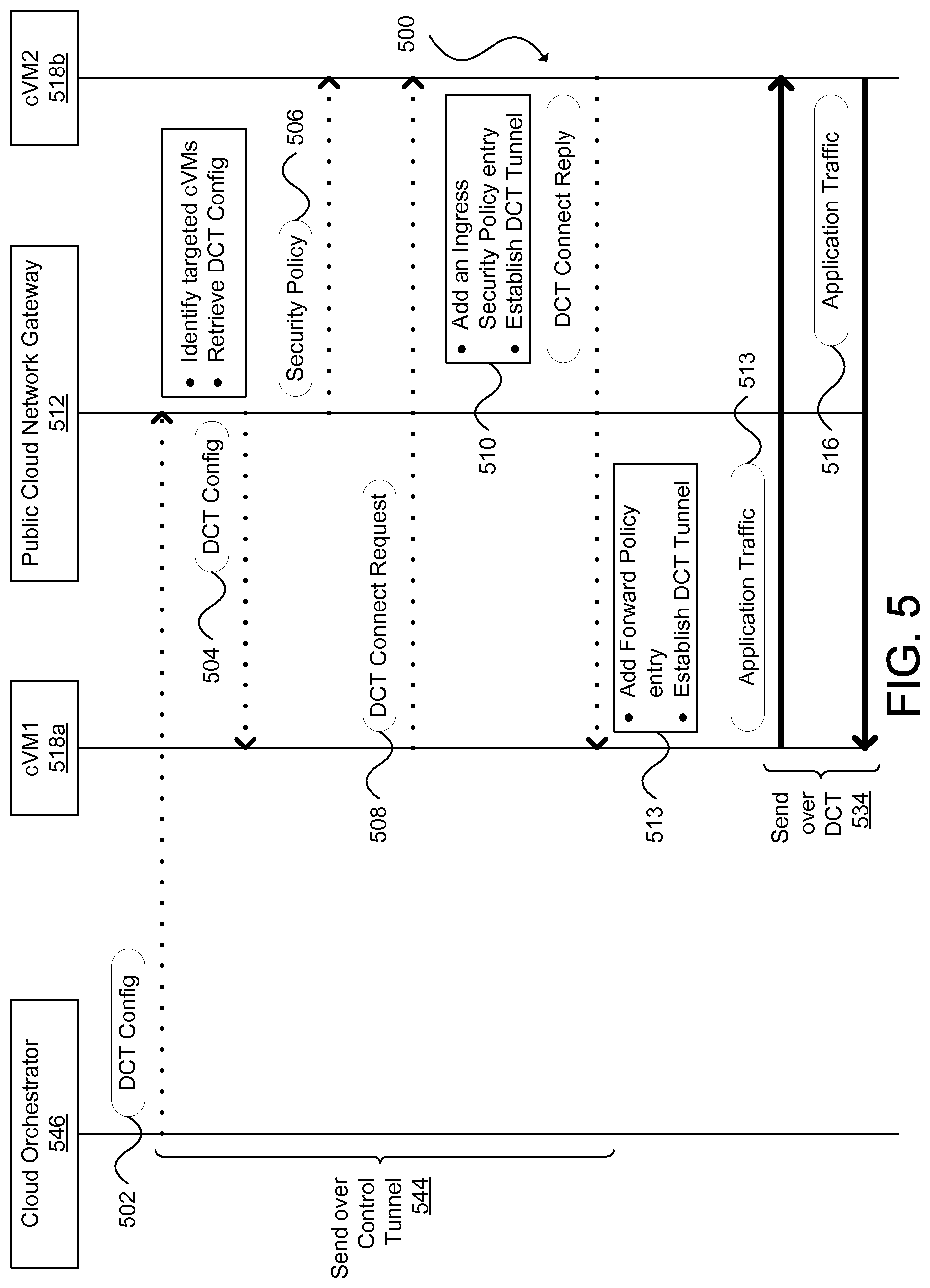
FIG. 5 illustrates an example data flow diagram for establishing communications between virtual machines in a hybrid cloud environment that can be utilized in another example embodiment;
FIG. 6 an example hybrid cloud network environment that can be utilized in another example embodiment; and
FIGS. 7A and 7B illustrate example systems that can be used in various example embodiments.
DESCRIPTION OF EXAMPLE EMBODIMENTS
The detailed description set forth below is intended as a description of various configurations of example embodiments and is not intended to represent the only configurations in which the subject matter of this disclosure can be practiced. The appended drawings are incorporated herein and constitute a part of the detailed description. The detailed description includes specific details for the purpose of providing a more thorough understanding of the subject matter of this disclosure. However, it will be clear and apparent that the subject matter of this disclosure is not limited to the specific details set forth herein and may be practiced without these details. In some instances, structures and components are shown in block diagram form in order to avoid obscuring the concepts of the subject matter of this disclosure.
Overview
Network policies can be used to optimize the flow of network traffic between virtual machines (VMs) in a hybrid cloud environment. In an example embodiment, one or more policies can drive a virtual switch controller, a hybrid cloud manager, a hypervisor manager, a virtual switch, or other orchestrator to create one or more direct tunnels that can be utilized by a respective pair of VMs to bypass the virtual switch and enable direct communication between the VMs. The virtual switch can send the VMs network and security policies to ensure that these policies are enforced. The VMs can exchange security credentials in order to establish the direct tunnel. The direct tunnel can be used by the VMs to bypass the virtual switch and allow the VMs to communicate with each other directly.
DETAILED DESCRIPTION
A computer network is a geographically distributed collection of nodes interconnected by communication links and segments for transporting data between endpoints, such as personal computers and workstations. Many types of networks are available, with the types ranging from Local Area Networks (LANs) and Wide Area Networks (WANs) to overlay networks and Software-Defined Networks (SDNs).
LANs typically connect nodes over dedicated private communications links located in the same general physical location, such as a building or campus. WANs, on the other hand, typically connect geographically dispersed nodes over long-distance communications links, such as common carrier telephone lines, optical lightpaths, synchronous optical networks (SONET), or synchronous digital hierarchy (SDH) links. LANs and WANs can include layer 2 (L2) and/or layer 3 (L3) networks and devices.
The Internet is an example of a WAN that connects disparate networks throughout the world, providing global communication between nodes on various networks. The nodes typically communicate over the network by exchanging discrete frames or packets of data according to predefined protocols, such as the Transmission Control Protocol/Internet Protocol (TCP/IP). In this context, a protocol can refer to a set of rules defining how the nodes interact with each other. Computer networks may be further interconnected by an intermediate network node, such as a router, to extend the effective size of each network.
Overlay networks generally allow virtual networks to be created and layered over a physical network infrastructure. Overlay network protocols, such as Virtual Extensible LAN (VXLAN), Network Virtualization using Generic Routing Encapsulation (NVGRE), Network Virtualization Overlays (NVO3), and Stateless Transport Tunneling (STT), can provide a traffic encapsulation scheme to allow network traffic to be carried across L2 and L3 networks over a logical tunnel.
Overlay networks can also include virtual segments, such as VXLAN segments in a VXLAN overlay network, which can include virtual L2 and/or L3 overlay networks over which virtual machines (VMs) communicate. The virtual segments can be identified through a virtual network identifier (VNI), such as a VXLAN network identifier, which can specifically identify an associated virtual segment or domain.
Network virtualization allows hardware and software resources to be combined in a virtual network. For example, network virtualization can allow multiple numbers of VMs to be attached to the physical network via respective virtual LANs (VLANs). The VMs can be grouped according to their respective VLAN, and can communicate with other VMs as well as other devices on the internal or external network.
Cloud computing can also be provided in a network to provide computing services using shared resources. Cloud computing can generally include Internet-based computing in which computing resources are dynamically provisioned and allocated to client or user computers or other devices on-demand, from a collection of resources available via the network (e.g., "the cloud"). Cloud computing resources, for example, can include any type of resource, such as computing, storage, and networking, among others. For instance, resources may include service devices (firewalls, deep packet inspectors, traffic monitors, load balancers, etc.), compute/processing devices (servers, CPUs, GPUs, random access memory, caches, etc.), and storage devices (e.g., network attached storages, storage area network devices, hard disk drives, solid-state devices, etc.), among others. In addition, such resources may be used to support virtual networks, VMs, databases, applications ("apps"), etc.
Cloud computing resources may include a "private cloud," a "public cloud," and/or a "hybrid cloud." A "private cloud" can be a cloud infrastructure operated by an enterprise for use by the enterprise, while a "public cloud" can be a cloud infrastructure that provides services and resources over a network for public use. A "hybrid cloud" can be a cloud infrastructure composed of two or more clouds that inter-operate or federate through cloud orchestration, cloud management, cloud automation, or similar technologies. A hybrid cloud can be thought of as an interaction between private and public clouds where a private cloud joins a public cloud and utilizes public cloud resources in a secure and scalable manner.
FIG. 1 illustrates an example hybrid cloud network environment 100 that can be utilized in an example embodiment. Hybrid cloud network environment 100 can include a plurality of networks or clouds, such as a private cloud 102 (e.g., an enterprise virtual datacenter) and a public cloud 104 separated by a WAN 106, such as the Internet. Although a hybrid cloud is sometimes defined as consisting of a private cloud and a public cloud, it should be understood that many aspects of this disclosure can be practiced in various configurations (e.g., two or more public clouds hosted by third party cloud providers and/or two or more private clouds of an enterprise located in different locations). The private cloud 102 and the public cloud 104 can be integrated using overlay network techniques, such as VXLAN, NVGRE, NVO3, STT, or other overlay network protocols known to those of ordinary skill. The private cloud 102 and public cloud 104 can be connected via a site-to-site tunnel or communication link 108 between a private cloud network gateway 110 and a public cloud network gateway 112. The private cloud network gateway 110 can be configured as a VM for extending the private cloud across the Internet to the public cloud 104 through the site-to-site tunnel 108. The public cloud network gateway 112 can be configured as a VM switch overlay for interconnecting workloads running in the public cloud 104 via secure access tunnels, and for forwarding network traffic to the private network 102 using the site-to-site tunnel 108. In an example embodiment, the private cloud network gateway 110 can be implemented using Intercloud Fabric.TM. Extender (ICX) from Cisco.RTM., Systems, Inc. of San Jose, Calif., the public cloud network gateway 112 can be implemented using Intercloud Fabric.TM. Switch (ICS) from Cisco.RTM., and the ICX/ICS pair can form an Intercloud Fabric.TM. Cloud (ICFCloud).
In some example embodiments, the private cloud network gateway 110 can establish, from the private cloud 102, the secure site-to-site tunnel 108 to interconnect with the public cloud network gateway 112, and interact with a virtual switch controller or Virtual Supervisor Module (VSM) 114. The VSM 114 can serve as a network controller for managing the network and security policies of the overlay network. In an example embodiment, the VSM 114 can be implemented in an active-standby model to ensure high availability, with a first VSM functioning in a primary role and a second VSM functioning in a secondary role. If the first VSM fails, the second VSM can take over control. A virtual chassis model can be used to represent VSM 114 and each virtual switch or Virtual Ethernet Module (VEM) under the VSM's control or within the VSM's domain, such as VEM 116a in the private cloud and public cloud VEM 116b. The high availability pair of VSMs 114 can be associated with slot numbers 1 and 2 in the virtual chassis, and the VEMs 116a and 116b can be sequentially assigned to the remaining slots. In the virtual chassis model, VSM 114 may be configured to provide control plane functionality for the virtual switches or VEMs 116a and 116b. The VEMs 116a and 116b can provide network connectivity and switching capability for VMs hosted on a corresponding server like a line card in a modular switching platform, and can operate as part of a data plane associated with the control plane of VSM 114. Unlike multiple line cards in a single chassis, each VEM can act as an independent switch from a forwarding perspective. In some example embodiments, the VEMs 116a and 116b may form a distributed virtual switch that can be controlled by the VSM 114. In an example embodiment, the VSM 114 and VEMs 116a and 116b can be implemented using Cisco Nexus.RTM. 1000V Series Switches.
The private cloud 102 can also include a hybrid cloud manager 120, which can be a management plane VM for auto-provisioning resources within the hybrid cloud network environment 100. The hybrid cloud manager 120 can be a management platform running in the private cloud 102, and may be responsible for providing hybrid cloud operations, translating between private cloud and public cloud interfaces, managing cloud resources, instantiating cloud gateways and cloud VMs though a private virtualization platform or hypervisor manager 122 and public cloud provider application programming interfaces (APIs). The hybrid cloud manager 120 may also monitor the health of all of the components of the network (e.g., cloud gateways, VMs, and communication links) and ensure high availability of those components.
In an example embodiment, the hybrid cloud manager 120 can be implemented as a virtual appliance, such as the Intercloud Fabric.TM. Director (ICFD) from Cisco.RTM.. The ICFD can be a hybrid cloud orchestration component that can provide a single point of management and consumption of hybrid cloud resources. That is, the ICFD can offer a single console so that users can provision workloads and associated policies. The ICFD can also expose northbound APIs, which allow users to programmatically manage their workloads in the hybrid cloud environment 100 or integrate with other cloud management platforms.
The private cloud 102 can include one or more physical servers 124 that each deploy a hypervisor 126 (also sometimes referred to as a virtual machine manager or a virtual machine monitor (VMM)). The hypervisor 126 may be computer software, firmware, or hardware that creates and runs one or more VMs, such as VMs 128 or cVMs 118. Although the cVMs 118 are not shown to be encapsulated by a hypervisor in this example, it will be appreciated that VMs may or may not be managed by a hypervisor. The hypervisor 126 can provide a respective operating system to one or more VMs. In some example embodiments, the hypervisor 126 may be a native or "bare metal" hypervisor that runs directly on hardware, but that may alternatively run under host software executing on hardware. The hypervisor 126 can be managed by the virtualization platform or hypervisor manager 122, such as vSphere.RTM. from VMware.RTM., Inc. of Palo Alto, Calif., Hyper-V.RTM. from Microsoft.RTM. Corp. of Seattle, Wash., XenServer.RTM. from Citrix.RTM. Systems, Inc. of Santa Clara, Calif., or Red Hat.RTM. Enterprise Virtualization from Red Hat.RTM., Inc. of Raleigh, N.C.
Each VM, including VMs 128 and cVMs 118, can host a private application. In some example embodiments, each public cloud VM 118 may be connected to the public cloud network gateway 112 via secure access tunnels, as discussed elsewhere herein. In some example embodiments, one or more cVMs 118 can be configured to operate as a public cloud firewall (not shown), such as an Intercloud Fabric.TM. Firewall or Virtual Security Gateway (VSG) from Cisco.RTM.. In some example embodiments, one or more cVMs 118 can be configured to operate as a public cloud router (not shown), such as an Intercloud Fabric.TM. Router or Cloud Services Router (CSR) from Cisco.RTM..
In some example embodiments, the public cloud network gateway 112 can establish, from the public cloud 104, the secure site-to-site tunnel 108 to interconnect with the private cloud network gateway 110, secure access tunnels to connect public cloud VMs (cVMs) 118, and monitor and report statistics for the public cloud VMs and any component failures in the public cloud 104. In some example embodiments, the private cloud network gateway 110 and the public cloud network gateway 112 can be deployed as a high-availability pair to provide redundancy. In some example embodiments, the public cloud network gateway 112 can include a cloud virtual switch or cloud Virtual Ethernet Module (cVEM) 116b that communicates with the VSM 114 to retrieve VM-specific network policies (e.g., port profiles), switches network traffic between public cloud VMs 118, switches network traffic between public cloud VMs and the private cloud 102, applies network policies, and monitors and reports VEM-related statistics.
In some example embodiments, each physical server, such as physical server 124, hosting a VM, including VM 128 and cVM 118, can include multiple Virtual Network Interface Cards (VNICs) (not shown) for providing specific functionality, such as control and/or data/packet transmission. For example, a VM on a physical server can include a vNIC that may be connected to a VEM, such as VEM 116a or cVEM 116b, for connecting the VM or cVM to the network. Each physical server 124 can include a vNIC for enabling control functionality, such as Small Computer Systems Interface over IP (iSCSI), Network File System (NFS) access, migration of VMs or cVMs, directly connected tunnels, discussed elsewhere herein, as well as other control functionality.
In some example embodiments, each public cloud VM 118 can include an agent (not shown) that provides for the network overlay logic for the public cloud VM. The agent can be deployed in the cVM as a secure tunnel driver. The agent can establish a secure access tunnel to connect the public cloud VM 118 to the public cloud network gateway 112, and monitor and report secure overlay-related statistics. In an example embodiment, the agent can be implemented using Intercloud Fabric.TM. Agent (ICA) from Cisco.RTM..
In some example embodiments, the secure site-to-site tunnel or communication link 108 can take one of several forms, such as various types of virtual private networks (VPNs) or Layer 2 (L2) tunneling protocols. For example, some example embodiments may utilize an open VPN (e.g., OpenVPN) overlay or an IP Security (IPSec) VPN based L3 network extension to provide the communication link 108. Some example embodiments may utilize a secure transport layer (i.e., L4) tunnel as the communication link 108 between the private cloud network gateway 110 and the public cloud network gateway 112, where the secure transport layer tunnel 108 can be configured to provide a link layer (i.e., L2) network extension between the private cloud 102 and the public cloud 104. Some example embodiments may establish the secure transport layer (i.e., L4) tunnel 108 (e.g., Transport Layer Security (TLS), Datagram TLS (DTLS), Secure Socket Layer (SSL), etc.) over the public network 104, and can build a secure L2 switch overlay that interconnects public cloud resources with private clouds (e.g., enterprise network backbones). In other words, the secure transport layer tunnel 108 can provide a link layer network extension between the private cloud 102 and the public cloud 104.
In an example embodiment, the private cloud network gateway 110 can use an L4 secure tunnel as the communication link 108 to connect to the cloud resources allocated in the public cloud 104. The L4 secure tunnel may be well-suited for use with corporate firewalls and Network Address Translation (NAT) devices due to the nature of the transport level protocols (e.g., UDP/TCP) and the transport layer ports opened for HTTP/HTTPS in the firewall. The L2 network can thus be further extended and connected to each of the cloud VMs 118 through the public cloud network gateway 112. With an L2 network overlay, instances of a particular private application VM can be seamlessly migrated to the overlay network dynamically created in the public cloud 104, without substantial impact to existing corporate infrastructure.
FIGS. 2A and 2B illustrate example approaches for distributing VM-to-VM network traffic in a public cloud 204 of a hybrid cloud network that can be utilized in some example embodiments. In FIG. 2A, the public cloud environment 204 can include a public cloud network gateway 212 and public cloud VMs 218a, 218b, 218c, and 218d. For example, a cloud manager (e.g., cloud manager 120 of FIG. 1) (not shown) can be used to deploy an intercloud fabric for integrating a private cloud (e.g., private cloud 102 of FIG. 1) (not shown) with a public cloud, such as the public cloud 204. The cloud manager can interface with a hypervisor manager (e.g., hypervisor manager 122 of FIG. 1) (not shown) to instantiate a VM (e.g., VM 128 of FIG. 1) (not shown) in the private cloud and configure the VM to operate as a private cloud network gateway (e.g., private cloud network gateway 110 of FIG. 1) (not shown). The cloud manager can also interface with a hypervisor manager in the public cloud 204 or cloud provider APIs to instantiate a plurality of public cloud VMs (e.g., cVMs 218a, 218b, 218c, or 218d). One or more of the cVMs can be configured to operate as the public cloud network gateway 212. One or more of the cVMs can be configured to operate as a public cloud firewall (not shown). One or more of the cVMs can be configured to operate as a public cloud router (not shown). One or more of the cVMs can be configured for migrating workloads from the private cloud to the public cloud 204.
The cloud manager can also establish a site-to-site tunnel or secure network extension 208 between the private cloud network gateway and the public cloud network gateway 212. As discussed, in some example embodiments, a public cloud VM agent 230 can be utilized to provide a compute environment and network overlay for the public cloud VMs 218a, 218b, 218c, and 218d. The cVMA 230 can be deployed in a public cloud VM as a secure tunnel driver that runs within the public cloud VM's operating system. The agent 230 can cause a cVM to direct network traffic to the secure overlay network by establishing a secure tunnel (e.g., access tunnels 232a and 232b) to connect to the public cloud network gateway 212 for allowing the cVMs to communicate with private cloud VMs and other public cloud VMs. The cVMA 230 can also collect secure overlay-related statistics.
In the public cloud 204, the access tunnel 232a can be used for secure communications between cVM 218a and 218d, and the access tunnel 232b can be used for secure communications between public cloud VM 218b and public cloud VM 218c. For instance, if the public cloud VM 218a desires to send a packet to the public cloud VM 218d, the packet can first be sent to the public cloud network gateway 212, where network and security policy may be enforced. Then the public cloud network gateway 212 may forward the packet to the cVM 218d. That is, packets sent between cVMs 218a and cVM 218d may pass through the public cloud network gateway 212 before arriving at the packets' intended destinations.
In certain situations, the public cloud network gateway 212 can become a bottleneck for a hybrid cloud network, such as when the public cloud network gateway is used to connect a large number of cVMs and/or large-sized cVMs. Under these circumstances, an alternative or additional process can be used for enabling communications between cVMs. FIG. 2B illustrates an example approach. In FIG. 2B, a direct connection or Directly Connected Tunnel (DCT) 234a may be established between cVM 218a and cVM 218d, and a direction connection or DCT 234b may be established between cVM 218b and 218c. Network traffic between cVMs 218a and 218d can bypass the public cloud network gateway 212 by transmitting the traffic through the directly connected tunnel 234a. Likewise, communications between cVMs 218b and 218c can bypass the public cloud network gateway 212 by sending the communications over the directly connected tunnel 234b.
As used herein, a direct connection or DCT can refer to a direct connection from an overlay network perspective rather than a direct physical connection. For example, cVMs 218a and 218d may not be directly connected to a same Ethernet (L2) hub, but can achieve L2 adjacency via VXLAN, NVGRE, NVO3, STT, or other suitable overlay network protocol. For instance, access tunnel 232a may be referred to as an indirect tunnel because traffic between cVMs 218a and 218d includes a hop over the public cloud network gateway 212. DCT 234a can be referred to as a direct tunnel because it does not include such hop. Although DCTs can reduce bandwidth requirements of the public cloud network gateway 212 and minimize the chances of the public cloud network gateway becoming a bottleneck for the hybrid cloud network, bypassing the public cloud network gateway may also result in network and security policy becoming unenforced.
FIG. 3 further illustrates an example approach for forwarding network traffic and enforcing security policy in a network environment similar to that of FIG. 2B. In FIG. 3, the public cloud environment 304 can include a public cloud network gateway 312 interconnected with public cloud VMs 318a and 318b. The cVM 318a can be assigned IP address 10.10.10.10 and MAC address aa.aa.aa, and the cVM 318b can be assigned IP address 20.20.20.20 and MAC address bb.bb.bb. The cVMs 318a and 318b may be indirectly connected via a secure access tunnel 332. That is, traffic between these cVMs transmitted along the access tunnel at one endpoint of the access tunnel can include a hop over the public cloud network gateway 312 before arriving at the other end of the access tunnel. The secure access tunnel 332 can be associated with tunnel identifier 1. The cVMs 318a and 318b may also be directly connected via a direct connection or DCT 334. The DCT 334 can be associated with tunnel identifier 2.
By default, the cVMs 318a and 318b can communicate with each other through the secure access tunnel 332 (and through the public cloud network gateway 312). The public cloud network gateway 312 can establish the access tunnel 332 as a default access tunnel during the initial deployment of a cVM and have network traffic between cVMs pass through the public cloud network gateway as a default forwarding policy. For example, cVM 318a's egress forwarding table 336 can be initialized to include an entry of "*" or all addresses for the destination IP address, "*" or all addresses for the destination MAC address, and a tunnel identifier of 1 to indicate that cVM 318's egress traffic should be forwarded on the default access tunnel 1, i.e., forwarded to the public cloud network gateway 312. The cVM 318b can have a similar egress forwarding table including a similar default forwarding policy. In the example embodiment of FIG. 3, the cVM 318b may have a default security policy or Access Control List (ACL) that denies all incoming traffic, which can be represented in the cVM 318b's ingress security policy table 338 as an entry including "*" or all addresses for the source address, "*" or all tunnels for the tunnel identifier, and a "Deny" rule for dropping incoming traffic corresponding to the source address and source tunnel. The cVM 318a may include a similar ingress security policy table with a default security policy or ACL.
To optimize network traffic flow in the public cloud environment 304 and ensure that security policy is enforced, policies can be defined for connecting a first cVM to a second cVM via a DCT. In an example embodiment, a DCT policy can be on-demand or enforced when any cVM mutually connected to a same public cloud network gateway attempt to communicate with one another. For instance, the public cloud network gateway can be configured to orchestrate the creation of a DCT tunnel between a pair of cVMs based on an initial attempted cVM-to-cVM communication via a secure access tunnel, such as an Address Resolution Protocol (ARP) request. In another example embodiment, a DCT policy can be application-driven or enforced by a cloud orchestration component (e.g., the VSM 114 of FIG. 1, cloud manager 120 of FIG. 1, hypervisor manager 122 of FIG. 1, or other suitable management interface) based on application network profiles or requirements (e.g., Application Network Profiles (ANPs) in the Cisco Application Centric Infrastructure (Cisco ACI.TM.)). For instance, the management interface can be utilized to configure a public cloud network gateway to set up one or more DCTs among a set of cVMs connected to the gateway based on the application network profiles or requirements.
In an example embodiment, a DCT policy can be statistics-driven or enforced according to metrics relating to the hybrid cloud network. For instance, a cVM agent and/or public cloud network gateway can monitor latency, bandwidth, throughput, response time, or other suitable processing and/or network performance measurement until such measurement is below a threshold, above a threshold, or otherwise satisfies a threshold condition. Upon satisfying the threshold condition, the public cloud network gateway can establish one or more DCTs to address the threshold condition. For example, a public cloud network gateway can be configured to create DCTs on-demand once CPU utilization reaches an upper bound and can revert to a previous network policy when CPU utilization is below a lower bound. As another example, a cVM agent can monitor and report network latency to a VSM (e.g., the VSM 114 of FIG. 1), cloud manager (e.g., cloud manager 120 of FIG. 1), hypervisor manager (e.g., hypervisor manager 122 of FIG. 1), or other suitable management interface. When network latency for the cVM reaches a minimum criterion, the management interface can direct the public cloud network gateway to establish one or more DCTs for that cVM to alleviate the network latency. In various example embodiments, other policies can be defined for establishing DCTs as would be known to one of ordinary skill in the art.
To establish the DCT 334 between the cVMs 318a and 316b, the public cloud network gateway 312 can send network address information and security information (e.g., keys credentials, certificates, or other authentication information) 340 relating to cVM 318b to the cVM 318a over the secure access tunnel 332. This can cause the egress forwarding policy table 336 to be updated with an entry, such as "20.20.20.20" for the destination IP address, "bb.bb.bb" for the destination MAC address, and tunnel identifier 2, indicating that traffic intended for the cVM 318b sent by the cVM 318a should be delivered over direct tunnel 334. The public cloud network gateway 312 can also send security policy information 342 to ensure applicable security policies are enforced. In this example, the security policy information 342 can cause the ingress security policy table 338 to be populated with an entry comprising "10.10.10.10" for a source address, tunnel identifier 2, and an "Allow" rule, which indicates that traffic originating from the source address sent over the DCT 334 can be accepted by the cVM 318b. In an example embodiment, physical servers hosting cVMs 318a and 318b can include control interfaces that can be used to form a control tunnel 344 between cVMs 318a and 318b. The first cVM's address and security information 340 and the second cVM's security policy information 342 can be sent over the control tunnel 344. In another example embodiment, such information can be sent over the secure access tunnel 332.
FIG. 4 illustrates an example data flow diagram 400 for establishing communications between VMs in a hybrid cloud environment that can be utilized in an example embodiment. Data flow diagram 400 may be used for enforcing an on-demand DCT policy, such as when a network is configured to establish a DCT tunnel upon any attempted communication between cVMs connected to the gateway, or the network has defined a statistics-driven DCT policy and a threshold condition corresponding to the policy is satisfied. In this example embodiment, a first VM 418a and a second VM 418b are each connected to a virtual switch or public cloud network gateway 412. A secure access tunnel 432 can be established between the cVMs during their deployment. The access tunnel 432 can include a hop over the public cloud network gateway 412. The cVM 418a's forwarding table (e.g., egress forwarding policy table 336 of FIG. 3) can be initialized with a default rule to send egress traffic to the public cloud network gateway 412 over the access tunnel 432. The cVM 418b's forwarding table may include a similar entry. The respective physical servers hosting cVMs 418a and 418b may include respective control interfaces such that a control tunnel 444 can also be created between cVMs 418a and 418b.
The first cVM 418a can attempt to communicate with the second cVM 418b, and may begin at 402 by sending an ARP request to the virtual switch or public cloud network gateway 412 to determine network address information for the second cVM. The ARP request can be sent over the secure access tunnel 432 based on the first cVM's default forwarding rule. Upon receiving the ARP request at 404, the virtual switch or public cloud network gateway 412 can resolve the requested network address information such as by looking up the requested network address in the switch's ARP cache to identify the MAC address of the second cVM 418b. The switch 412 can also retrieve the second cVM's security information, such as keys, credentials, certificates, or other information necessary for establishing a DCT with the second cVM 418b. Keys, credentials, or certificates can include passwords, private keys generated from public-key cryptography methods (e.g., Rivest-Shamir-Adleman (RSA), Digital Signature Algorithm (DSA), Elliptical Curve Digital Signature Algorithm (ECDSA), Diffie-Helman (DH), Elliptic Curve Diffie-Hellman (ECDH)), or secret keys generated from symmetric-key cryptography methods (e.g., International Data Encryption Algorithm (IDEA), Data Encryption Standard (DES), Triple-DES, Advanced Encryption Standard (AES), ARCFOUR (RC4), Blowfish, Twofish, Carlisle Adams Stafford Tavares (CAST), etc. In various example embodiments, other authentication methods (e.g., Kerberos, NT LAN Manager (NTLM), and keyboard-interactive, etc.), and new authentication methods as they become available. The switch 412 can send the ARP reply to the first cVM 418a over the default tunnel 432. The DCT configuration information can be piggybacked onto the ARP reply.
The virtual switch 412 can also fetch the security policy rules relevant to the second cVM 418b and may send the security policies to the second cVM's control interface at 406. At 408, after the first cVM 418a has received the ARP reply and the second cVM's security information, the first cVM can begin the DCT establishment process or protocol by sending a DCT connection request to the second cVM 418b over the control tunnel 444. The DCT connection request can include information for authenticating the first cVM 418a derived from the second cVM's security information, as well as keys, credentials, certificates, or other information necessary to establish a DCT with the first cVM.
At 410, after the second cVM 418b can receive the security policies from the virtual switch 412 and the DCT connection request from the first cVM 418a, the second cVM may attempt to authenticate the first cVM using the first cVM's authentication information within the DCT connection request. Upon authentication of the first cVM 418a, the second cVM 418b can establish itself as one endpoint of the DCT 434, such as by updating its ingress security policy table using the received security policies. The second cVM 418b may then send a DCT connection reply that includes information authenticating the second cVM with information derived from the first cVM's security information. As a part of the DCT establishment process or protocol, the second cVM 418b may also update its egress forwarding table with an entry for forwarding egress traffic to the first cVM 418a through the DCT 434.
At 413, after the first cVM 418a has received the DCT connection reply, the first cVM may attempt to authenticate the second cVM 418b using the second cVM's authentication information within the DCT connection reply. If the second cVM 418b is authenticated, the first cVM 418a may establish itself as the other endpoint of the DCT 434, such as by updating its egress forwarding policy table with an entry forwarding traffic to the second cVM through the DCT. The first cVM 418a may subsequently send its application traffic directly to the second cVM 418b via the DCT 434 at 414, and the second cVM 418b can send its application traffic directly to the first cVM 418a via the DCT 434 at 416.
FIG. 5 illustrates an example data flow diagram 500 for establishing communications between VMs in a hybrid cloud environment that can be utilized in another example embodiment. Data flow diagram 500 may be used for enforcing an application-driven DCT policy. For instance, instead of being acted upon according to real-time cVM-to-cVM traffic, such as in the case with an on-demand or statistics-driven DCT policy, an application-driven policy may be based on ANPs or application network requirements. Thus, it may be required to have prior knowledge of the application-level network topology and security requirements of an application before its deployment. Another difference between data flow diagrams 400 and 500 may lie in the first few steps of each process. That is 502 and 504 of the data flow diagram 500 may differ from 402 and 404 of the data flow diagram 400 but 506 through 516 of the data flow diagram 500 may be the same or substantially similar to 406 through 416 of the data flow diagram 400.
The data flow diagram 500 may begin by defining an ANP based on prior knowledge of the application's network and security requirements. The ANP can include configuration of endpoints (e.g., network and security policies) and security information (e.g., keys, credentials, certificates, or other authentication information. A cloud orchestration component 546 (e.g., the VSM 114 of FIG. 1, cloud manager 120 of FIG. 1, hypervisor manager 122 of FIG. 1, or other management interface) can be used to push the ANP to a virtual switch or public cloud network gateway 512 over a control tunnel 544 at 502. In another example embodiment, the ANP can be sent through a secure access tunnel. Based on receiving the ANP from the cloud orchestrator 546, the virtual switch 512 can build one or more DCT tunnels 534 between various VM pairs (e.g., cVMs 518a and 518b) one-by-one until each application node, configured to bypass the virtual switch according to the ANP, is connected to a DCT. For example, the virtual switch 512 can send DCT configuration to one or more cVMs over the control tunnel 544. In another example embodiment, the DCT configuration information can be sent over a secure access tunnel. As discussed, 506 through 516 can be the same or substantially the same as 406 through 416 of FIG. 4.
FIG. 6 illustrates an example hybrid cloud network environment 600 that can be utilized in another example embodiment. The hybrid cloud network environment 600 can include a private cloud (e.g., private cloud 102 of FIG. 1) (not shown) interconnected to a public cloud 604 via a secure network extension or site-to-site tunnel 608. The public cloud 604 can comprise a plurality of hosts, such as a web host 648, an application host 650, and a database host 652. Each host can be implemented as a virtual machine or a bare metal host. The web host 648 can include a public cloud network gateway 612a that interconnects the host to the private cloud by the secure site-to-site tunnel 608. The public cloud network gateway 612a can also interconnect the web host 648 to the application host 650 by a secure inter-gateway tunnel 654a.
The web host 648 can also include web containers 656a and 656b. In an example embodiment, the public cloud network gateway 612a can also be implemented as a container. A container is a kind of lightweight virtual machine utilized in operating system level virtualization. Operating system level virtualization is a type of server virtualization in which the kernel of an operating system may be capable of providing multiple isolated user space instances or containers. Unlike whole system server virtualization, in which a single server can host multiple operating systems, operating system level virtualization can be used to partition a single operating system among multiple containers. Containers may use less memory and CPU than whole system VMs running similar workloads because only a single kernel may be executed using containers whereas multiple kernels may be executed using whole system VMs. However, containers can raise security concerns not applicable to whole system VMs due to operating system resources being shared.
The application host 650 can include a public cloud network gateway 612b and application containers 656c and 656d. The public cloud network gateway 612b can be used to interconnect the application host 650 to the web host 648 via the secure inter-gateway tunnel 654a, and the application host 650 to the database host 652 via the secure inter-gateway tunnel 654b. The database host 652 can include a public cloud network gateway 612c and database container 656e. As illustrated in FIG. 6, the public cloud 604 can be used to implement a conventional multi-tier or three-tier architecture including a web or presentation tier corresponding to the web host 648, an application or logic tier corresponding to the application host 650, and a data or database tier corresponding to the database host 652.
In the example embodiment of FIG. 6, one or more application-driven DCT policies can be applied to the public cloud network 604 to create the multi-tier application architecture and the secure inter-gateway tunnels 654a and 654b. Using this approach, the public cloud network gateways can provide default network connectivity to every container (e.g., via access tunnels) while optimizing network traffic flow by using the DCTs as a primary data path for exchanging application traffic.
FIG. 7A illustrates an example embodiment of a physical server 724, such as physical server 124 of FIG. 1. The physical server 724 can include hardware 758, a hypervisor 726 (e.g., hypervisor 126 of FIG. 1), and a public cloud virtual machine 718 (e.g., cVM 118 of FIG. 1). Hardware 758 can represent any machine or apparatus capable of accepting, performing logic operations on, storing, or displaying data, and may include a processor 760 and memory 762. In this example embodiment, a cVM agent 730 (e.g., cVM agent 230 of FIG. 2) can be installed on the cVM 718 when the cVM is deployed on the physical server 724. The cVM agent 730 can include software, such as a network overlay module 764 and a DCT protocol module 766. The network overlay module 764 can be used to provide a compute environment and network overlay for the cVM 718, and can include logic for establishing a secure tunnel (e.g., access tunnel 332 of FIG. 3) to connect the cVM 718 to a public cloud network gateway (not shown). The DCT protocol module 766 can include logic for performing the DCT protocol or process discussed with respect to FIGS. 4 and 5. The memory 762 can be used to store an egress forwarding policy table, such as egress forwarding policy table 336 of FIG. 3, and an ingress security policy table, such as ingress security policy table 338 of FIG. 3.
FIG. 7B illustrates an example embodiment of a public cloud network gateway 712, such as the public cloud network gateway 112 of FIG. 1. The public cloud network gateway 712 can include hardware 768 and public cloud network gateway software, such as an Input/Output (I/O) interface 770 and a DCT protocol module 772. I/O interface 770 can enable the public cloud network gateway 712 to communicate with components located within the same public cloud as the gateway, as well as with other public cloud network gateways and with a private cloud (e.g., private cloud 102 of FIG. 1) (not shown).
I/O interface 770 can include a site-to-site tunnel interface 774, an inter-gateway tunnel interface 776, and an access tunnel interface 778. Site-to-site tunnel interface 774 can be used by the public cloud network gateway 712 to communicate with a private cloud network gateway (e.g., private cloud network gateway 110 of FIG. 1) (not shown) over a secure site-to-site tunnel, such as secure site-to-site tunnel 108 of FIG. 1. Inter-gateway tunnel interface 776 can be used by the public cloud network gateway 712 to communicate with other public cloud network gateways over inter-gateway tunnels, such as inter-gateway tunnels 654a and 654b of FIG. 6. Access tunnel interface 778 can be used by the public cloud network gateway 712 to communicate with cVMs (e.g., cVM 718) over secure access tunnels, such as access tunnel 332 of FIG. 3 or over an overlay network, such as a VXLAN, NVGRE, NVO3, STT, or other overlay network.
The DCT protocol module 772 can include logic for performing the DCT protocol or process discussed with respect to FIGS. 4 and 5. Hardware 768 can represent any machine or apparatus that is capable of accepting, performing logic operations on, storing, or displaying data, and may include a processor 780 and memory 782. Memory 782 can include, for example, a hash map, table, or other suitable data structure for storing the network address information of cVMs in the public cloud, such as an ARP cache, a cVM MAC address-to-VEM IP address mapping, a forwarding table, or other network address data structure. Memory 782 can also include a database or other suitable data structure for storing DCT configuration information, including security policies and security information (e.g., keys, credentials, certificates, or other authentication information) for each cVM attached to the public cloud network gateway 712. Memory 782 can further include one or more tables, lists, or other data structures for storing data associated with certain operations described herein.
In an example embodiment, the public cloud network gateway 712, physical server 724, and/or physical switches connected to these components (not shown) can be network elements, which can encompass network appliances, servers, routers, switches, firewalls gateways, bridges, load balancers, modules, or any other suitable device, proprietary component, element, or object operable to exchange information in a network environment. Network elements may include any suitable hardware, software, components, modules, or objects that facilitate the operations thereof, as well as suitable interfaces for receiving, transmitting, and/or otherwise communicating data or information in a network environment. This may be inclusive of appropriate algorithms and communication protocols that allow for the effective exchange of data or information.
In regards to the internal structure associated with the above network elements, each of the public cloud network gateway 712, physical server 724, and/or a physical switches connected to these components (not shown) can include memory elements for storing information to be used in the operations disclosed herein. Additionally, physical server 724 may also include virtual memory elements for storing information associated with virtual partitions, such as public cloud virtual machine 718. Each of VSM 702, virtualized system 706, VEM 714, and/or a connected physical switch may keep information in any suitable memory element (e.g., random access memory (RAM), read-only memory (ROM), erasable programmable ROM (EPROM), electrically erasable programmable ROM (EEPROM), application specific integrated circuit (ASIC), etc.), software, hardware, or in any other suitable component, device, element, or object where appropriate and based on particular needs. Any of the memory elements discussed herein (e.g., memory 762 and 782) should be construed as being encompassed within the broad term memory element or memory. Information being used, tracked, sent, or received by each of the public cloud network gateway 712, physical server 724, and/or a connected physical switch can be provided in any database, register, queue, table, cache, control list, or other storage structure, all of which can be referenced at any suitable timeframe. Any such storage options may be included within the broad term memory element or memory as used herein.
In an example embodiment, each of the public cloud network gateway 712, physical server 724, and/or a connected physical switch may include software modules (e.g., DCT protocol) to achieve, or to foster operations as outlined herein. In other example embodiments, such operations may be carried out by hardware, implemented externally to these elements, or included in some other network device to achieve the intended functionality. Alternatively, these elements may include software (or reciprocating software) that can coordinate in order to achieve the operations, as outlined herein. In still other embodiments, one or all of these devices may include any suitable algorithms, hardware, software, components, modules, interfaces, or objects that facilitate the operations thereof.
For clarity of explanation, in some instances the subject matter of this disclosure may be presented as including individual functional blocks including functional blocks comprising devices, device components, steps or routines in a method embodied in software, or combinations of hardware and software.
Note that in certain example embodiments, the optimization and/or switch overlay bypass functions outlined herein may be implemented by logic encoded in one or more tangible, non-transitory media (e.g., embedded logic provided in an application specific integrated circuit (ASIC), digital signal processor (DSP) instructions, software (potentially inclusive of object code and source code) to be executed by a processor, or other similar machine, etc.). The computer-readable storage devices, mediums, and memories can include a cable or wireless signal containing a bit stream and the like. However, when mentioned, non-transitory computer-readable storage media expressly exclude media such as energy, carrier signals, electromagnetic waves, and signals per se.
Methods according to the above-described example embodiments can be implemented using computer-executable instructions that are stored or otherwise available from computer readable media. Such instructions can comprise, for example, instructions and data which cause or otherwise configure a general purpose computer, special purpose computer, or special purpose processing device to perform a certain function or group of functions. Portions of computer resources used can be accessible over a network. The computer executable instructions may be, for example, binaries, intermediate format instructions such as assembly language, firmware, or source code. Examples of computer-readable media that may be used to store instructions, information used, and/or information created during methods according to described examples include magnetic or optical disks, flash memory, USB devices provided with non-volatile memory, networked storage devices, and so on.
Devices implementing methods according to the subject matter of this disclosure can comprise hardware, firmware and/or software, and can take any of a variety of form factors. Typical examples of such form factors include laptops, smart phones, small form factor personal computers, personal digital assistants, and so on. Functionality described herein also can be embodied in peripherals or add-in cards. Such functionality can also be implemented on a circuit board among different chips or different processes executing in a single device, by way of further example.
The instructions, media for conveying such instructions, computing resources for executing them, and other structures for supporting such computing resources are means for providing the functions described in these disclosures.
Although a variety of examples and other information was used to explain aspects within the scope of the appended claims, no limitation of the claims should be implied based on particular features or arrangements in such examples, as one of ordinary skill would be able to use these examples to derive a wide variety of implementations. Further and although some subject matter may have been described in language specific to examples of structural features and/or method steps, it is to be understood that the subject matter defined in the appended claims is not necessarily limited to these described features or acts. For example, such functionality can be distributed differently or performed in components other than those identified herein. Rather, the described features and steps are disclosed as examples of components of systems and methods within the scope of the appended claims.
* * * * *
References
-
blog.twinstrata.com/2012/07/101/5-benefits-of-a-storage-gateway-in-the-cloud
-
Ibarb.co.uk/whats-next
-
cisco.com/en/US/prod/collateral/switches/ps9441/ps9902/white_paper_c11-558242.pdf
-
css-cloud.com/platform/enterprise-cloud-gateway.php
-
download.openvz.org/doc/openvz-intro.pdf
-
lerach.cz/en/products/golem
-
flexiant.com
-
nielsen-admosphere.eu/products-and-services/simmetry-audience-measurement-technology
-
nielsen.com/us/en/solutions/measurement/television.html
-
docs.openstack.org/nova/latest/user/filter-scheduler.html
-
en.wikipedia.orq/w/index.php?title=Filter_%28software%29&oldid=594544359
-
en.wikipedia.ord/w/index.php?title=Pipeline2/028Unix%29&oldid=606980114
D00000
D00001
D00002
D00003
D00004
D00005
D00006
D00007
D00008
XML
uspto.report is an independent third-party trademark research tool that is not affiliated, endorsed, or sponsored by the United States Patent and Trademark Office (USPTO) or any other governmental organization. The information provided by uspto.report is based on publicly available data at the time of writing and is intended for informational purposes only.
While we strive to provide accurate and up-to-date information, we do not guarantee the accuracy, completeness, reliability, or suitability of the information displayed on this site. The use of this site is at your own risk. Any reliance you place on such information is therefore strictly at your own risk.
All official trademark data, including owner information, should be verified by visiting the official USPTO website at www.uspto.gov. This site is not intended to replace professional legal advice and should not be used as a substitute for consulting with a legal professional who is knowledgeable about trademark law.