RFID transponder
Ahokas , et al. May 11, 2
U.S. patent number 11,005,152 [Application Number 15/818,166] was granted by the patent office on 2021-05-11 for rfid transponder. This patent grant is currently assigned to Confidex OY. The grantee listed for this patent is Confidex OY. Invention is credited to Heikki Ahokas, Miika Pylvanainen.


| United States Patent | 11,005,152 |
| Ahokas , et al. | May 11, 2021 |
RFID transponder
Abstract
An RFID transponder, comprising an antenna, comprising a radiating element an IC, and a ground plane arranged under the radiating element, the ground plane being solid without openings. The radiating element comprises a near field communication section extending over the edge of the ground plane for enabling near field communication of the antenna by the ground plane from backside of the RFID transponder.
| Inventors: | Ahokas; Heikki (Tampere, FI), Pylvanainen; Miika (Ylojarvi, FI) | ||||||||||
|---|---|---|---|---|---|---|---|---|---|---|---|
| Applicant: |
|
||||||||||
| Assignee: | Confidex OY (Tampere,
FI) |
||||||||||
| Family ID: | 57406095 | ||||||||||
| Appl. No.: | 15/818,166 | ||||||||||
| Filed: | November 20, 2017 |
Prior Publication Data
| Document Identifier | Publication Date | |
|---|---|---|
| US 20180151942 A1 | May 31, 2018 | |
Foreign Application Priority Data
| Nov 25, 2016 [EP] | 16200609 | |||
| Current U.S. Class: | 1/1 |
| Current CPC Class: | G06K 19/0723 (20130101); H01Q 1/48 (20130101); H01Q 1/2225 (20130101); G06K 19/07773 (20130101); H01Q 1/2208 (20130101); G06K 19/07722 (20130101); H01Q 7/00 (20130101); H01Q 9/0421 (20130101); G06K 1/20 (20130101) |
| Current International Class: | H01Q 1/22 (20060101); G06K 19/077 (20060101); G06K 19/07 (20060101); H01Q 1/48 (20060101); H01Q 7/00 (20060101); H01Q 9/04 (20060101); G06K 1/20 (20060101) |
References Cited [Referenced By]
U.S. Patent Documents
| 6265977 | July 2001 | Vega |
| 7109867 | September 2006 | Forster |
| 7652636 | January 2010 | Forster |
| 8717244 | May 2014 | Joyce, Jr. |
| 10171133 | January 2019 | Kyllonen |
| 2004/0201522 | October 2004 | Forster |
| 2005/0024287 | February 2005 | Jo |
| 2006/0044192 | March 2006 | Egbert |
| 2006/0054710 | March 2006 | Forster |
| 2006/0208955 | September 2006 | Kai |
| 2006/0214801 | September 2006 | Murofushi |
| 2006/0244605 | November 2006 | Sakama |
| 2007/0040028 | February 2007 | Kawamata |
| 2007/0171071 | July 2007 | Chiu |
| 2007/0200782 | August 2007 | Hayama |
| 2007/0216591 | September 2007 | Tsirline |
| 2008/0231421 | September 2008 | Tuttle |
| 2009/0224056 | September 2009 | Kwon |
| 2010/0065647 | March 2010 | Ritamaki |
| 2011/0017832 | January 2011 | Ritamaki |
| 2011/0115611 | May 2011 | Tsirline |
| 2012/0019363 | January 2012 | Fein |
| 2013/0050045 | February 2013 | Chacinski |
| 2013/0271265 | October 2013 | Finn |
| 2014/0266622 | September 2014 | Alicot |
| 2015/0129666 | May 2015 | Butler |
| 2017/0316299 | November 2017 | Ritamaki |
| 2016059285 | Apr 2016 | WO | |||
Other References
|
European Search Report issued in EP Application No. EP16200609.2 dated May 2, 2017; parent EP Application. cited by applicant. |
Primary Examiner: Alkassim, Jr.; Ab Salam
Attorney, Agent or Firm: Placker, Esq; Jeffrey T. Holland & Knight LLP
Claims
The invention claimed is:
1. An RFID transponder for printing and encoding, comprising a printable surface on a top side of the transponder, an antenna element under the printable surface, the antenna element comprising an antenna and an IC coupled to the antenna, the antenna comprising at least two radiating elements, a ground plane arranged under the radiating elements, the ground plane being solid without openings, only one of the radiating elements comprising a near field communication section extending over an edge of the ground plane for enabling near field communication of the antenna by the ground plane from a backside of the RFID transponder.
2. The RFID transponder as claimed in claim 1, wherein a spacer layer made of a dielectric material is arranged between the antenna element and the ground plane.
3. The RFID transponder as claimed in claim 1, wherein the antenna comprises two radiating elements arranged at a distance from each other, and the IC being situated between said two radiating elements.
4. The RFID transponder as claimed in claim 1, wherein the at least two radiating elements are quadrangles.
5. The RFID transponder as claimed in claim 4, wherein the near field communication section is provided by prolongation of two parallel sides of one of the quadrangle, the near field communication section thus being situated at one edge of the radiating element.
Description
RELATED APPLICATIONS
The subject application claims the benefit of European Patent Application No. 16200609.2, filed on Nov. 25, 2016. The content of which is herein incorporated by reference in its entirety.
BACKGROUND
The invention relates to an RFID transponder.
It is known to code RFID transponders by using RFID printer-encoders. An RFID printer-encoder typically prints visual information like barcode or human readable on top of the RFID transponder. Same or, alternatively, different information is electronically programmed inside the IC memory of the RFID transponder by the reader antenna of the printer.
However, some RFID transponders have structures which may isolate the antenna of the transponder from the radiation of the reader antenna of the printer. Said structure of the RFID transponder is usually the ground plane of the antenna of said transponder. For instance, if the printer has its reader antenna below the ground plane, it is usually not possible to couple the reader antenna to the antenna of the RFID transponder. Therefore the RFID transponder cannot be encoded in said printer.
BRIEF DESCRIPTION
Viewed from a first aspect, there can be provided an RFID transponder, comprising an antenna, comprising a radiating element, an IC, a ground plane arranged under the radiating element, the ground plane being solid without openings, the radiating element comprising a near field communication section extending over the edge of the ground plane for enabling near field communication of the antenna by the ground plane from backside of the RFID transponder.
Thereby an RFID transponder which may be encoded in most RFID printers may be achieved. The near field communication section enables near field communication by and beyond the ground plane. Down to this, there is no need, for instance, for a separate secondary antenna, which would be adapted for near field communication with e.g. a RFID printer-encoder or a RFID encoder.
The RFID transponder is characterised by what is stated in the characterising part of the independent claim. Some other embodiments are characterised by what is stated in the other claims. Inventive embodiments are also disclosed in the specification and drawings of this patent application. The inventive content of the patent application may also be defined in other ways than defined in the following claims. The inventive content may also be formed of several separate inventions, especially if the invention is examined in the light of expressed or implicit sub-tasks or in view of obtained benefits or benefit groups. Some of the definitions contained in the following claims may then be unnecessary in view of the separate inventive ideas. Features of the different embodiments of the invention may, within the scope of the basic inventive idea, be applied to other embodiments.
In one embodiment, a spacer layer made of a dielectric material is arranged between the antenna element and the ground plane.
In one embodiment, the antenna comprises two radiating elements arranged at a distance from each other, and the IC being situated between said two radiating elements.
In one embodiment, the radiating element is quadrangle.
In one embodiment, the near field communication section is provided by prolongation of two parallel sides of the quadrangle, the near field communication section thus being situated at one edge of the radiating element.
In one embodiment, the radiating element is a meandering element.
In one embodiment, the radiating element is a PIFA element.
In one embodiment, the radiating element is a loop element.
In one embodiment, the near field communication section is provided on at least two edges of the radiating element by extending said edges over the edge of the ground plane.
In one embodiment, the antenna comprises at least two radiating elements, and only one of said radiating elements comprises the near field communication section.
In one embodiment, the near field communication section is provided by a projection extending from the radiating element and having an elongated aspect ratio.
In one embodiment, the projection comprises at least one bend.
BRIEF DESCRIPTION OF FIGURES
Some embodiments illustrating the present disclosure are described in more detail in the attached drawings, in which
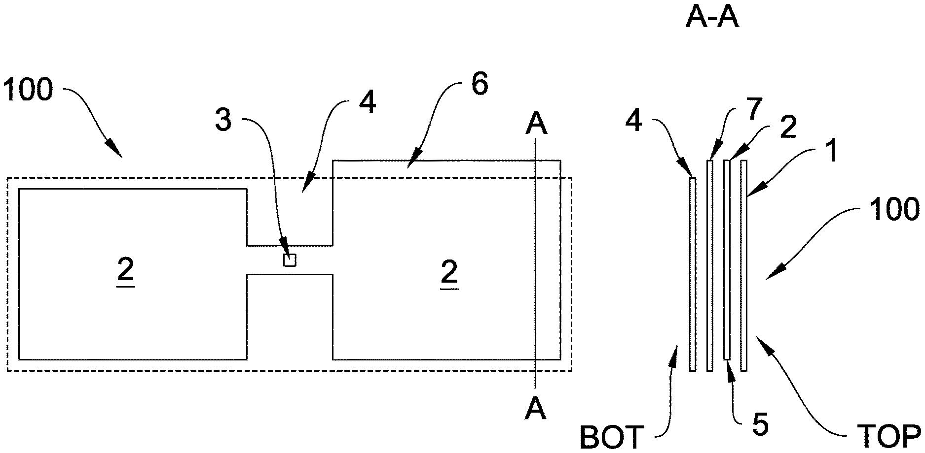
FIG. 1 is a schematic top view of an RFID transponder,
FIG. 2 is a schematic top view of another RFID transponder,
FIG. 3 is a schematic top view of a third RFID transponder, and
FIG. 4 is a schematic top view of a fourth RFID transponder.
In the figures, some embodiments are shown simplified for the sake of clarity. Similar parts are marked with the same reference numbers in the figures.
DETAILED DESCRIPTION
FIG. 1 is a schematic top view of an RFID transponder. The RFID transponder 100 may comprise a printable surface or face element 1, an antenna element 2, and an IC 3. The RFID transponder 100 further comprises a ground plane 4 that is made of metal or some other electrically conductive material or composition. The ground plane 4 is solid without openings and arranged under the antenna element 2.
Layers of the RFID transponder 100 are typically attached together with suitable adhesive layers and sealed by e.g. a silicone liner.
The RFID transponder 100 may further comprise a spacer layer 7 that is arranged to make distance between the antenna element 2 and the ground plane 4. The spacer layer 7 is made of a dielectric material, such as polyethylene PE, polypropylene PP polyethylene terephthalate PET, in a solid or a foamed form.
The printable surface 1 is arranged on the top side of the transponder 100. The surface 1 may be a thin material layer manufactured from e.g. paper or plastic based material, or a layer of paint(s) and/or lacquer(s).
The antenna element 2 and the IC 3 (together with further electronic components, if any) may be arranged to a structural module such as an inlay 5 comprising a dielectric substrate.
The edges or peripheral shape of the ground plane 4 is shown by dash line in Figures. The radiating element 2 comprises a near field communication section 6 that extends over the edge of the ground plane 4 for enabling near field communication of the antenna by the ground plane 4 from backside of the RFID transponder 100.
In the embodiment shown in FIG. 1, the antenna comprises two radiating elements 2 the shape of which is quadrangle and which are arranged at a distance from each other. The IC 3 is situated between the radiating elements 2. The near field communication section 6 is provided by prolongation of two parallel sides of one of the quadrangles, so the near field communication section 6 is situated at one edge of the radiating element 2.
For example, if the reader antenna of an RFID printer-encoder, such as Zebra RZ600, is on the bottom side BOT of the RFID transponder 100, the near field communication section 6 makes it possible to couple said reader antenna with the antenna element 2 of the transponder although the reader antenna is situated opposite side of the ground plane 4 compared to the antenna element 2 of the transponder, thus enabling encoding the RFID transponder 100.
The radiating element 2 as such may be of any type of radiating element suitable for the RFID transponder 100. Some further examples of the radiating element are a meandering element, a PIFA element and a loop element.
Also the shape of the radiating element 2 as well as number of the radiating elements 2 may vary. For instance, the number of the radiating elements 2 may be one, two, three, four or even more.
Furthermore, the coupling of the IC 3 and the radiating element 2 may vary: a galvanic, an inductive or capacitive coupling may be used.
FIG. 2 is a schematic top view of another RFID transponder. According to an aspect, the near field communication section 6 is provided on at least two edges of the radiating element 2 by extending said edges over the edge of the ground plane 4. In the embodiment shown in FIG. 2, all the edges of the radiating elements 2 extends over the ground plane 4--except the edge being towards the IC 3. An advantage is that the RFID transponder 100 can be encoded in various types of encoders having diverse antenna configurations.
It is to be noted that the IC 3 may also be arranged on/in the near field communication section 6.
FIG. 3 is a schematic top view of a third RFID transponder. In this embodiment, only one of plurality of radiating elements 2 comprises the near field communication section 6. This embodiment is quite similar to that shown in FIG. 1, except the near field communication section 6 being arranged at the end edge of the radiating element 2. An advantage is that the production of the RFID transponder may be implemented in simple and effective way.
FIG. 4 is a schematic top view of a fourth RFID transponder. According to an aspect, the near field communication section 6 is provided by a projection extending from the radiating element 2 and having an elongated aspect ratio. In the embodiment shown in FIG. 4, the projection comprises one bend. The projection may also be straight, meandering, curved etc. An advantage is that the near field communication section 6 may be designed so that its influence on the main antenna or the radiating element(s) is negligible.
The invention is not limited solely to the embodiments described above, but instead many variations are possible within the scope of the inventive concept defined by the claims below. Within the scope of the inventive concept the attributes of different embodiments and applications can be used in conjunction with or replace the attributes of another embodiment or application.
The drawings and the related description are only intended to illustrate the idea of the invention. The invention may vary in detail within the scope of the inventive idea defined in the following claims.
REFERENCE SYMBOLS
1 printable coating 2 an antenna element 3 IC 4 ground plane 5 inlay 6 near field communication section 7 spacer layer 100 RFID transponder BOT bottom side TOP top side
* * * * *
D00000
D00001
D00002
D00003
D00004
XML
uspto.report is an independent third-party trademark research tool that is not affiliated, endorsed, or sponsored by the United States Patent and Trademark Office (USPTO) or any other governmental organization. The information provided by uspto.report is based on publicly available data at the time of writing and is intended for informational purposes only.
While we strive to provide accurate and up-to-date information, we do not guarantee the accuracy, completeness, reliability, or suitability of the information displayed on this site. The use of this site is at your own risk. Any reliance you place on such information is therefore strictly at your own risk.
All official trademark data, including owner information, should be verified by visiting the official USPTO website at www.uspto.gov. This site is not intended to replace professional legal advice and should not be used as a substitute for consulting with a legal professional who is knowledgeable about trademark law.