Optical lens system
Kim , et al. May 11, 2
U.S. patent number 11,002,945 [Application Number 16/393,891] was granted by the patent office on 2021-05-11 for optical lens system. This patent grant is currently assigned to ELCOMTEC CO., LTD.. The grantee listed for this patent is ELCOMTEC CO., LTD.. Invention is credited to Jae Hoon Cho, Sun Myung Kang, Se Jin Kim.


| United States Patent | 11,002,945 |
| Kim , et al. | May 11, 2021 |
Optical lens system
Abstract
An optical lens system is disclosed. The optical lens system includes a first lens that has negative refractive power, a second lens that has positive refractive power, a third lens that has positive refractive power, a fourth lens that has refractive power, a fifth lens that has positive refractive power, a sixth lens that has negative refractive power, an aperture located between the second lens and the third lens, and conditional expressions of "-1.4<tan .theta./f<-1.1" and "4.0<TTL/BFL<6.0" are satisfied when .theta. is an angle of view of the optical lens system in a diagonal direction, f is a focal length of the optical lens system, TTL is a distance on an optical axis from the object-side surface of the first lens to the sensor, and BFL is a distance on the optical axis from the sensor-side surface of the sixth lens to the sensor.
| Inventors: | Kim; Se Jin (Seoul, KR), Cho; Jae Hoon (Suwon-si, KR), Kang; Sun Myung (Osan-si, KR) | ||||||||||
|---|---|---|---|---|---|---|---|---|---|---|---|
| Applicant: |
|
||||||||||
| Assignee: | ELCOMTEC CO., LTD.
(Pyeongtaek-si, KR) |
||||||||||
| Family ID: | 62025210 | ||||||||||
| Appl. No.: | 16/393,891 | ||||||||||
| Filed: | April 24, 2019 |
Prior Publication Data
| Document Identifier | Publication Date | |
|---|---|---|
| US 20190265443 A1 | Aug 29, 2019 | |
Related U.S. Patent Documents
| Application Number | Filing Date | Patent Number | Issue Date | ||
|---|---|---|---|---|---|
| PCT/KR2017/011562 | Oct 19, 2017 | ||||
Foreign Application Priority Data
| Oct 25, 2016 [KR] | 10-2016-0138969 | |||
| Current U.S. Class: | 1/1 |
| Current CPC Class: | G02B 13/0045 (20130101); G02B 13/00 (20130101); G02B 5/20 (20130101); G02B 9/62 (20130101); G03B 7/085 (20130101); G02B 13/06 (20130101) |
| Current International Class: | G02B 13/00 (20060101); G02B 13/06 (20060101); G02B 5/20 (20060101); G03B 7/085 (20210101); G02B 9/62 (20060101) |
References Cited [Referenced By]
U.S. Patent Documents
| 9374513 | June 2016 | Chen et al. |
| 9377605 | June 2016 | Chung et al. |
| 9557534 | January 2017 | Liao |
| 10054766 | August 2018 | Shin et al. |
| 10215959 | February 2019 | You |
| 2014/0368931 | December 2014 | Noda et al. |
| 2015/0098135 | April 2015 | Chung et al. |
| 2015/0268446 | September 2015 | Chen et al. |
| 2015/0350503 | December 2015 | Chen et al. |
| 2016/0178871 | June 2016 | You |
| 2016/0259150 | September 2016 | Shin et al. |
| 104238084 | Dec 2014 | CN | |||
| 104516094 | Apr 2015 | CN | |||
| 105717611 | Jun 2016 | CN | |||
| 105938238 | Sep 2016 | CN | |||
| 2014-044250 | Mar 2014 | JP | |||
| 2016-0075015 | Jun 2016 | KR | |||
| 2016-0108080 | Sep 2016 | KR | |||
| 201428336 | Jul 2014 | TW | |||
Other References
|
International Search Report issued in PCT/KR2017/011562; dated Jan. 30, 2018. cited by applicant . Search Report mailed by the Chinese Patent Office dated Sep. 26, 2020, which corresponds to Chinese Patent Application No. 201780062497.1 and is related to U.S. Appl. No. 16/393,891. cited by applicant . Notice of Allowance mailed by the Chinese Patent Office dated Nov. 4, 2020, which corresponds to Chinese Patent Application No. 201780062497.1 and is related to U.S. Appl. No. 16/393,891. cited by applicant. |
Primary Examiner: Huang; Wen
Attorney, Agent or Firm: Studebaker & Brackett PC
Parent Case Text
CROSS-REFERENCE TO RELATED APPLICATIONS
The present application is a continuation of International Patent Application No. PCT/KR2017/011562, filed Oct. 19, 2017, which is based upon and claims the benefit of priority to Korean Patent Application No. 10-2016-0138969, filed on Oct. 25, 2016. The disclosures of the above-listed applications are hereby incorporated by reference herein in their entirety.
Claims
What is claimed is:
1. An optical lens system including a first lens, a second lens, a third lens, a fourth lens, a fifth lens, and a sixth lens sequentially arranged from an object side to a sensor side between an object and a sensor on which an image of the object is focused, wherein the first lens has a negative refractive power and a sensor-side surface of the first lens is concave in a paraxial region, the second lens has positive refractive power, the third lens has positive refractive power and an object-side surface of the third lens is convex in the paraxial region, the fourth lens has refractive power, an object-side surface of the fourth lens is convex in the paraxial region and concave on the periphery of an effective diameter of the paraxial region, a sensor-side surface of the fourth lens is concave in the paraxial region, both an object-side surface and a sensor-side surface of the fourth lens are aspheric, the fifth lens has positive refractive power, an object-side surface of the fifth lens is concave in the paraxial region and aspheric, the sixth lens has negative refractive power, a sensor-side surface of the sixth lens is concave and has at least one inflection point in the effective diameter, both an object-side surface and a sensor-side surface of the sixth lens are aspheric, an aperture is located between the second lens and the third lens, and the following conditional expression is satisfied when .theta. is an angle of view of the optical lens system in a diagonal direction, f is a focal length of the optical lens system, TTL is a distance on an optical axis from the object-side surface of the first lens to the sensor, and BFL is a distance on the optical axis from the sensor-side surface of the sixth lens to the sensor, -1.4<tan .theta./f<-1, and 4.0<TTL/BFL<6. <Conditional Expression>
2. The optical lens system of claim 1, wherein the object-side surface of the sixth lens is convex in the paraxial region and concave on the periphery in the effective diameter of the paraxial region.
3. The optical lens system of claim 1, wherein an object-side surface of the first lens is convex in the effective diameter.
4. The optical lens system of claim 1, wherein an object-side surface of the second lens is concave in the effective diameter.
5. The optical lens system of claim 1, wherein a sensor-side surface of the third lens is convex in the paraxial region.
6. The optical lens system of claim 1, wherein a sensor-side surface of the fifth lens is convex in the paraxial region.
7. The optical lens system of claim 1, wherein the fourth lens is formed of a material having a refractive index of 1.6 or greater.
8. The optical lens system of claim 1, wherein the sixth lens is formed of a material having a refractive index of 1.6 or greater.
9. The optical lens system of claim 1, wherein the fourth lens and the sixth lens are formed of a material having a refractive index of 1.6 or greater, and the refractive index of the material forming the fourth lens is greater than the refractive index of the material forming the sixth lens.
10. The optical lens system of claim 1, wherein the first lens, the second lens, the third lens, and the fifth lens are formed of a material having a refractive index of 1.5 to 1.6.
11. The optical lens system of claim 1, wherein at least one of the fourth lens and the sixth lens is formed of plastic.
12. The optical lens system of claim 1, wherein the fourth lens has negative refractive power.
13. The optical lens system of claim 1, wherein the following conditional expression is further satisfied when f1 is a focal length of the first lens, -1.7<f1/f<-1.4. <Conditional Expression>
14. The optical lens system of claim 1, wherein the following conditional expression is further satisfied when V1 is the Abbe number of the first lens and V2 is the Abbe number of the second lens, 50<(V1+V2)/2<60. <Conditional Expression>
15. The optical lens system of claim 1, wherein the following conditional expression is further satisfied when CRA (MAX) is a maximum value of a chief ray angle of the optical lens system, 30.0 deg<CRA(MAX)<35.0 deg. <Conditional Expression>
16. The optical lens system of claim 1, wherein the following conditional expression is further satisfied when FSL is a distance on the optical axis between the object-side surface of the first lens and the aperture, 0.2<FSL/TTL<0.3. <Conditional Expression>
Description
FIELD
The present disclosure relates to an optical lens system, and more particularly, to an optical lens system which may be mounted on an imaging camera module.
BACKGROUND
An imaging camera module includes an optical lens system including at least one lens and an image sensor that receives light passing through the optical lens system and converts the received light into an electric signal. Solid-state image sensing devices such as a charge coupled device (CCD) or a complimentary metal oxide semiconductor image sensor (CMOS image sensor) have commonly been used as image sensors.
Recently, camera modules have been widely employed in electronic devices such as smartphones, tablet computers, lab-top computers, and the like. Such electronic devices have advanced to become smaller and thinner in order to improve user convenience and aesthetic sense. The conventional camera devices also tend to grow smaller and thinner. In line with this, a camera module mounted on such an electronic device is also required to be small and thin.
Recent camera modules require a lens having a wide angle of view to capture a larger amount of information by one shot. However, it is difficult to design a lens which may have a wide angle of view, may be used in combination with a high-resolution image sensor, and may have excellent optical performance such as aberration and distortion.
Therefore, a high-performance optical lens system which is smaller, has a wide angle of view, and is used in combination with a high-resolution image sensor is required to be developed.
SUMMARY
An aspect of the present disclosure provides a high-performance optical lens system which is smaller, has a wide angle of view, and is used in combination with a high resolution image sensor.
Another aspect of the present disclosure provides an optical lens system which includes lenses formed of plastic and uses low-priced materials, thus achieving excellent economical efficiency.
According to an aspect of the present disclosure, there is provided an optical lens system including a first lens, a second lens, a third lens, a fourth lens, a fifth lens, and a sixth lens sequentially arranged from an object side to a sensor side between an object and a sensor on which an image of the object is focused, in which the first lens has negative refractive power and a sensor-side surface of the first lens is concave in a paraxial region, the second lens has positive refractive power, the third lens has positive refractive power and an object-side surface of the third lens is convex in the paraxial region, the fourth lens has refractive power, an object-side surface of the fourth lens is convex in the paraxial region and concave on the periphery of an effective diameter of the paraxial region, a sensor-side surface of the fourth lens is concave in the paraxial region, both an object-side surface and a sensor-side surface of the fourth lens are aspheric, the fifth lens has positive refractive power, an object-side surface of the fifth lens is concave in the paraxial region and aspheric, the sixth lens has negative refractive power, a sensor-side surface of the sixth lens is concave and has at least one inflection point in the effective diameter, both an object-side surface and a sensor-side surface of the sixth lens are aspheric, an aperture is located between the second lens and the third lens, and the following conditional expression is satisfied when .theta. is an angle of view of the optical lens system in a diagonal direction, f is a focal length of the optical lens system, TTL is a distance on an optical axis from the object-side surface of the first lens to the sensor, and BFL is a distance on the optical axis from the sensor-side surface of the sixth lens to the sensor. -1.4 tan .theta./f<-1.1 4.0<TTL/BFL<6.0 <Conditional Expression>
In an embodiment of the present disclosure, the object-side surface of the sixth lens may be convex in the paraxial region and concave on the periphery in the effective diameter of the paraxial region.
In an embodiment of the present disclosure, an object-side surface of the first lens may be convex in the effective diameter.
In an embodiment of the present disclosure, an object-side surface of the second lens may be concave in the effective diameter.
In an embodiment of the present disclosure, a sensor-side surface of the third lens may be convex in the paraxial region.
In an embodiment of the present disclosure, a sensor-side surface of the fifth lens may be convex in the paraxial region.
In an embodiment of the present disclosure, the fourth lens may be formed of a material having a refractive index of 1.6 or greater.
In an embodiment of the present disclosure, the sixth lens may be formed of a material having a refractive index of 1.6 or greater.
In an embodiment of the present disclosure, the fourth lens and the sixth lens may be formed of a material having a refractive index of 1.6 or greater, and the refractive index of the material forming the fourth lens may be greater than the refractive index of the material forming the sixth lens.
In an embodiment of the present disclosure, the first lens, the second lens, the third lens, and the fifth lens may be formed of a material having a refractive index of 1.5 to 1.6.
In an embodiment of the present disclosure, at least one of the fourth lens and the sixth lens may be formed of plastic.
In an embodiment of the present disclosure, the fourth lens may have negative refractive power.
In an embodiment of the present disclosure, the following conditional expression may further be satisfied when f1 is a focal length of the first lens. -1.7<f1/f<-1.4 <Conditional Expression>
In an embodiment of the present disclosure, the following conditional expression may further be satisfied when V1 is the Abbe number of the first lens and V2 is the Abbe number of the second lens. 50<(V1+V2)/2<60 <Conditional Expression>
In an embodiment of the present disclosure, the following conditional expression may further be satisfied when CRA (MAX) is a maximum value of a chief ray angle of the optical lens system. 30.0 deg<CRA(MAX)<35.0 deg <Conditional Expression>
In an embodiment of the present disclosure, the following conditional expression may further be satisfied when FSL is a distance on the optical axis between the object-side surface of the first lens and the aperture. 0.2<FSL/TTL<0.3 <Conditional Expression>
The optical lens system according to an embodiment of the present disclosure is small, has a wide angle of view, and can be used in combination with a high resolution image sensor.
Further, since the optical lens system according to an embodiment of the present disclosure includes the lenses formed of plastic and uses low-priced materials, excellent economical efficiency may be achieved.
BRIEF DESCRIPTION OF THE DRAWINGS
FIG. 1 is a view illustrating a configuration of lenses of an optical lens system according to a first embodiment of the present disclosure.
FIG. 2 is view illustrating a configuration of lenses of an optical lens system according to a second embodiment of the present disclosure.
FIG. 3 is a view illustrating a configuration of lenses of an optical lens system according to a third embodiment of the present disclosure.
FIG. 4 is view illustrating a configuration of lenses of an optical lens system according to a fourth embodiment of the present disclosure.
DETAILED DESCRIPTION
Hereinafter, embodiments of the present disclosure will be described in detail with reference to the accompanying drawings. In describing the present disclosure, if it is determined that a detailed description of known functions and components associated with the present disclosure unnecessarily obscure the gist of the present disclosure, the detailed description thereof will be omitted. The terms used henceforth are used to appropriately express the embodiments of the present disclosure and may be altered according to a person of a related field or conventional practice. Therefore, the terms should be defined on the basis of the entire content of this specification.
Hereinafter, an optical lens system according to a first embodiment of the present disclosure will be described with reference to FIG. 1.
FIG. 1 is a view illustrating a configuration of an optical lens system according to an embodiment of the present disclosure.
Referring to FIG. 1, an optical lens system according to the present disclosure includes a first lens L1, a second lens L2, a third lens L3, a fourth lens L4, a fifth lens L5, and a sixth lens L6 are located between an object corresponding to a subject and a sensor IS on which an image of the object is focused. The first to sixth lenses L1, L2, L3, L4, L5, and L6 are sequentially arranged from the object side to the sensor IS side.
Each of the lens has opposing surfaces facing each other. In one lens, a surface facing the object side corresponds to an entry surface through which light enters the lens. Further, in one lens, a surface facing the sensor IS side corresponds to an exit surface through which light exits. In this embodiment, a surface which is an object-side surface and an entry surface of an nth lens is denoted by Sn1 and a surface which is a sensor-side surface and an exit surface of the nth lens is denoted by Sn2. Accordingly, an object-side surface and entry surface of the first lens L1 is denoted by S11, and a sensor-side surface and exit surface thereof is denoted by S12. Also, an object-side surface and entry surface of the second lens L2 is denoted by S21, and a sensor-side surface and exit surface thereof is denoted by S22. Also, an object-side surface and entry surface of the third lens L3 is denoted by S31, and a sensor-side surface and exit surface thereof is denoted by S32. Also, an object-side surface and entry surface of the fourth lens L4 is denoted by S41, and a sensor-side surface and exit surface thereof is denoted by S42. Also, an object-side surface and entry surface of the fifth lens L5 is denoted by S51, and a sensor-side surface and exit surface thereof is denoted by S52. Also, an object-side surface and entry surface of the sixth lens L6 is denoted by S61, and a sensor-side surface and exit surface thereof is denoted by S62.
The optical lens system includes an aperture S. The aperture S may be located to cover a sensor the second lens L2 and the third lens L3. In some cases, the aperture S may be located over the sensor-side surface S22 of the second lens L2. The aperture S may block a partial amount of light to adjust the amount of light irradiated into the optical lens system.
The optical lens system may include an optical filter OF. The optical filter OF may be located between the sixth lens L6 and the sensor IS. The optical filter OF may block light other than light of a band detected by the sensor IS. More specifically, the optical filter OF may block light of an infrared band when the sensor IS is an image sensor detecting visible light, and block light of a visible light band when the sensor IS is an image sensor detecting an infrared ray.
The sensor IS may be an image sensor IS which receives light passing through the lenses and converts the received light into an electric signal. The sensor IS is located on a rear surface of the sixth lens L6 so that light passing through the first to sixth lenses L1 to L6 forms an image on the object-side surface of the sensor IS.
Each of the lenses of the optical lens system of the present disclosure has the following characteristics.
The first lens L1 has negative (-) refractive power. The object-side surface S11 of the first lens L1 is convex in an effective diameter, and the sensor-side surface S12 thereof is concave in a paraxial region. The object-side surface S11 of the first lens L1 may be convex or concave in a paraxial region. Here, the paraxial region refers to a portion close to an optical axis and refers to a portion close to an optical axis in the effective diameter of the lens. The first lens L1 has a meniscus shape convex toward the object side in the effective diameter. Both the object-side surface S11 and the sensor-side surface S12 of the first lens L1 are formed as aspheric surfaces. The first lens L1 is formed of plastic, and the plastic forming the first lens L1 preferably has a refractive index larger than 1.5 and smaller than 1.6.
The second lens L2 has positive (+) refractive power. The object-side surface S21 of the second lens L2 is concave in the effective diameter, and the sensor-side surface S22 is convex in the paraxial region. The object-side surface S21 of the second lens L2 may be convex or concave in the paraxial region. Both the object-side surface S21 and the sensor-side surface S22 of the second lens L2 are formed as aspheric surfaces. The second lens L2 is formed of plastic, and the plastic forming the second lens L2 preferably has a refractive index larger than 1.5 and smaller than 1.6.
The third lens L3 has positive refractive power. The object-side surface S31 of the third lens L3 is convex in the paraxial region and the sensor-side surface S32 is also convex in the paraxial region. Both the object-side surface S31 and the sensor-side surface S32 of the third lens L3 are formed as aspheric surfaces. The third lens L3 is formed of plastic, and the plastic forming the third lens L3 is preferably a refractive index greater than 1.5 and smaller than 1.6.
The fourth lens L4 has negative refractive power. The object-side surface S41 of the fourth lens L4 is convex in the paraxial region and is concave on the periphery in the effective diameter of the paraxial region. Accordingly, the object-side surface S41 of the fourth lens L4 is substantially concave in the entire effective diameter but a curvature radius based on the paraxial region has a positive value. The sensor-side surface S42 of the fourth lens L4 is convex in the paraxial region. Both the object-side surface S41 and the sensor-side surface S42 of the fourth lens L4 are formed as aspheric surfaces.
The fourth lens L 4 is formed of plastic. The fourth lens L4 is formed of a material having high refractive index, relative to the first, second, third, and fifth lenses. Specifically, the fourth lens L4 is formed of a material having a refractive index of 1.6 or greater. More preferably, the fourth lens L4 may be formed of a material having a refractive index of 1.65 or greater.
The fifth lens L5 has positive refractive power. The sensor-side surface S52 of the fifth lens L5 is convex in the paraxial region. Both the object-side surface S51 and the sensor-side surface S52 of the fifth lens L5 are formed as aspheric surfaces. The fifth lens L5 is formed of plastic, and the plastic forming the fifth lens L5 preferably has a refractive index larger than 1.5 and smaller than 1.6.
The sixth lens L6 has negative refractive power. The object-side surface S61 of the sixth lens L6 is convex in the paraxial region and concave on the periphery in the effective diameter of the paraxial region. Accordingly, the object-side surface S61 of the sixth lens L6 is substantially concave in the entire effective diameter but has a positive radius of curvature with respect to the paraxial region. The sensor-side surface S62 of the sixth lens L6 is convex in the paraxial region. Both the object-side surface S61 and the sensor-side surface S62 of the sixth lens L6 are formed as aspheric surfaces.
The sixth lens L6 is formed of plastic. The sixth lens L6 is formed of a material having a high refractive index, relative to the first, second, third, and fifth lenses. Specifically, the sixth lens L6 is formed of a material having a refractive index of 1.6 or greater. More preferably, the sixth lens L6 may be formed of a material having a refractive index of 1.65 or greater.
Although both the fourth lens L4 and the sixth lens L6 are formed of a material having a refractive index of 1.6 or greater, the refractive index of the material forming the fourth lens L4 may be greater than the refractive index of the material forming the sixth lens.
Further, the optical lens system of the present disclosure satisfies the following conditional expression. -1.4<tan .theta./f<-1.1 <Conditional Expression 1>
Here, .theta. is an angle of view of the optical lens system in a diagonal direction, and f is a focal length of the optical lens system.
If the conditional expression 1 is satisfied, the optical lens system may realize wide-angle performance. In this embodiment, the angle of view in the diagonal direction is 120.0 degrees, which realizes the wide angle performance. As in the present embodiment, in a state in which the angle of view .theta. is sufficiently large, the focal length f is preferably within a range satisfying Conditional Expression 1. If the focal length f is so long as to exceed a lower limit of Conditional Expression 1, a total track length TTL of the optical lens system may be lengthened. Also, if the focal length f is so short as to exceed an upper limit of Conditional Expression 1, a spherical aberration and a coma aberration may increase to degrade optical performance. 4.0<TTL/BFL<6.0 <Conditional Expression 2>
Here, TTL is a distance on the optical axis from the object-side surface S11 of the first lens L1 to the sensor IS, and BFL is a distance on the optical axis from the sensor-side surface S62 of the sixth lens L6 to the sensor IS.
If Conditional Expression 2 is satisfied, the total track distance TTL of the optical lens system is limited. As a result, a height of a camera module equipped with the optical lens system of the present disclosure may be reduced. This may advantageously make an electronic device in which the camera module is mounted slimmer. -1.7<f1/f<-1.4 <Conditional Expression 3>
Here, f1 is a focal length of the first lens L1 and f is a focal length of the optical lens system.
If Conditional Expression 3 is satisfied, an optical lens system having a wide angle and excellent optical performance may be manufactured. 50<(V1+V2)/2<60 <Conditional Expression 4>
Here, V1 is the Abbe number of the first lens L1, and V2 is the Abbe number of the second lens L2.
The first lens L1 and the second lens L2 may be formed of a material having the Abbe number of 50 or greater on average. Thus, a chromatic aberration of the optical lens system may be corrected effectively. In addition, through this configuration, low manufacturing cost may be maintained. 30.0 deg<CRA(MAX)<35.0 deg <Conditional Expression 5>
Here, CRA (MAX) is a maximum value of a chief ray angle of the optical lens system.
If Conditional Expression 5 is satisfied, the optical lens system advantageously has a wide angle and excellent optical performance. 0.2<FSL/TTL<0.3 <Conditional Expression 6>
Here, FSL is a distance between the object-side surface S11 of the first lens L1 to the aperture S on the optical axis, and TTL is a distance from the object-side surface S11 of the first lens L1 to the sensor IS on the optical axis.
Conditional Expression 6 defines the position of the aperture S in the optical lens system. If Conditional Expression 6 is satisfied, the aperture S is substantially located near the first lens L1 and the second lens L2.
The following table describes optical characteristics of the optical lens system according to a first embodiment of the present disclosure illustrated in FIG. 1.
TABLE-US-00001 TABLE 1 Component r d N f V First lens(L1) S11* -17.3708 0.2500 1.5340 -2.0921 55.8559 S12* 1.2000 0.3305 Second lens(L2) S21* 8.1705 0.3167 1.5465 3.0453 56.0928 S22* -2.0614 0.1000 Aperture S Infinity 0.1000 Third lens (L3) S31* 2.2396 0.4741 1.5465 1.6724 56.0928 S32* -1.4286 0.1000 Fourth lens (L4) S31* 3.0710 0.2300 1.6574 -3.4545 21.4744 S32* 1.2668 0.2079 Fifth lens (L5) S51* -2.2194 0.6208 1.5465 1.5668 56.0928 S52* -0.6789 0.1000 Sixth lens (L6) S61* 1.3895 0.3600 1.6455 -2.0625 23.5165 S62* 0.6108 0.2300 Focal Length(F) 1.4315 Fno 1.9800 CRA(MAX) 33.9907 TTL 3.9200 DFOV 120.0 In the above table, * on the lens surface indicates that the corresponding lens surface is aspheric. In the above table, r is a radius of curvature of the corresponding lens surface, d is a thickness of the corresponding lens on the optical axis when the corresponding lens surface is the object-side surface, or a distance between an exit surface of the corresponding lens to a next component (lens, aperture S, or filter) when the corresponding lens surface is a sensor-side surface. Thus, d of S22 refers to a distance between the sensor-side surface S22 of the second lens L2 and the aperture S located between the second lens L2 and the third lens L3. Also, d of S62 refers to a distance between the sensor-side surface S62 of the sixth lens L6 and a filter located on a rear side of the sixth lens L6. N is a refractive index of the corresponding lens, f is a focal length of the corresponding lens, and V is the Abbe number of the corresponding lens. Here, a distance unit of r, d, and f is mm.
The focal length F is a focal length of the entire optical lens system, CRA is a maximum value of the chief ray angle of the optical lens system, TTL is a total track length of the optical lens system, and, specifically, a distance on the optical axis from the object-side surface S11 of the first lens L1 to the sensor IS, and DFOV is an angle of view of the optical lens system in the diagonal direction. Here, a unit of F and TTL is mm, and an angle of CRA and DFOV is degree.
The aspheric surfaces of the lens surfaces of the optical lens system according to the first embodiment of the present disclosure illustrated in FIG. 1 satisfies the following aspheric surface equation.
.function..times..times..times..times..times..times..times..times..times.- <> ##EQU00001##
Here, z denotes a distance from an apex of a lens in an optical axis direction, and y denotes a distance to a direction perpendicular to the optical axis. R denotes a radius of curvature at the apex of the lens, and K denotes a conic constant. A.sub.2 to A.sub.12 denote aspheric surface coefficients, respectively.
The following table is a table regarding the aspheric surface coefficients of the aspheric surfaces of the optical lens system according to the first embodiment of the present disclosure illustrated in FIG. 1.
TABLE-US-00002 TABLE 2 K A2 A4 A6 A8 A10 A12 S11 0.0000 0.4898 -0.8740 0.6921 -0.2610 0.0423 0.0000 S12 0.1928 0.7390 2.1821 -21.2720 82.9568 -173.1436 147.0673 S21 99.0000 0.0455 -0.0735 -2.6281 4.4360 -12.3945 12.5269 S22 0.0000 0.3204 -3.2054 18.9712 -82.4468 179.3358 -153.5533 S31 10.9585 0.1599 0.1465 -6.9104 17.3975 -8.4085 -46.2617 S32 3.0009 -0.2435 1.7038 -1.5479 -18.0237 58.9576 -58.6302 S41 0.0000 -1.3350 0.1172 17.4425 -93.1034 191.9022 -136.7373 S42 1.0251 -0.9266 0.2572 5.2783 -19.0560 26.7389 -13.7392 S51 6.0917 0.8364 -2.3802 5.1492 -4.2636 -1.2787 2.8543 S52 -0.7977 0.6209 -0.1424 -2.6312 6.2935 -5.3817 1.5956 S61 -31.1830 0.0301 -0.9605 1.0915 -0.7186 0.2954 -0.0527 S62 -5.9769 -0.1524 -0.0642 0.1561 -0.1148 0.0381 -0.0051
Referring to FIG. 1 and the above two tables, each lens of the optical lens system according to the first embodiment of the present disclosure satisfies the above-described characteristics.
The following table shows calculation of the values of the Conditional Expression 1 to Conditional Expression 6 described above in the optical lens system of the present embodiment.
TABLE-US-00003 TABLE 3 Target value Target of first Conditional Expression value embodiment Conditional -1.4 < tan.theta./f < -1.1 tan.theta./f -1.2100 Expression 1 Conditional 4.0 < TTL/BFL < 6.0 TTL/BFL 5.3699 Expression 2 Conditional -1.7 < f1/f < -1.4 f1/f -1.4615 Expression 3 Conditional 50 < (V1 + V2)/2 < 60 (V1 + 56.0928 Expression 4 V2)/2 Conditional 30.0deg < CRA(MAX) < CRA 33.9907 Expression 5 35.0deg (MAX) Conditional 0.2 < FSL/TTL < 0.3 FSL/TTL 0.2544 Expression 6
As illustrated in the above table, it can be seen that the optical lens system of the first embodiment of the present disclosure satisfies all of Conditional Expression 1 to Conditional Expression 6.
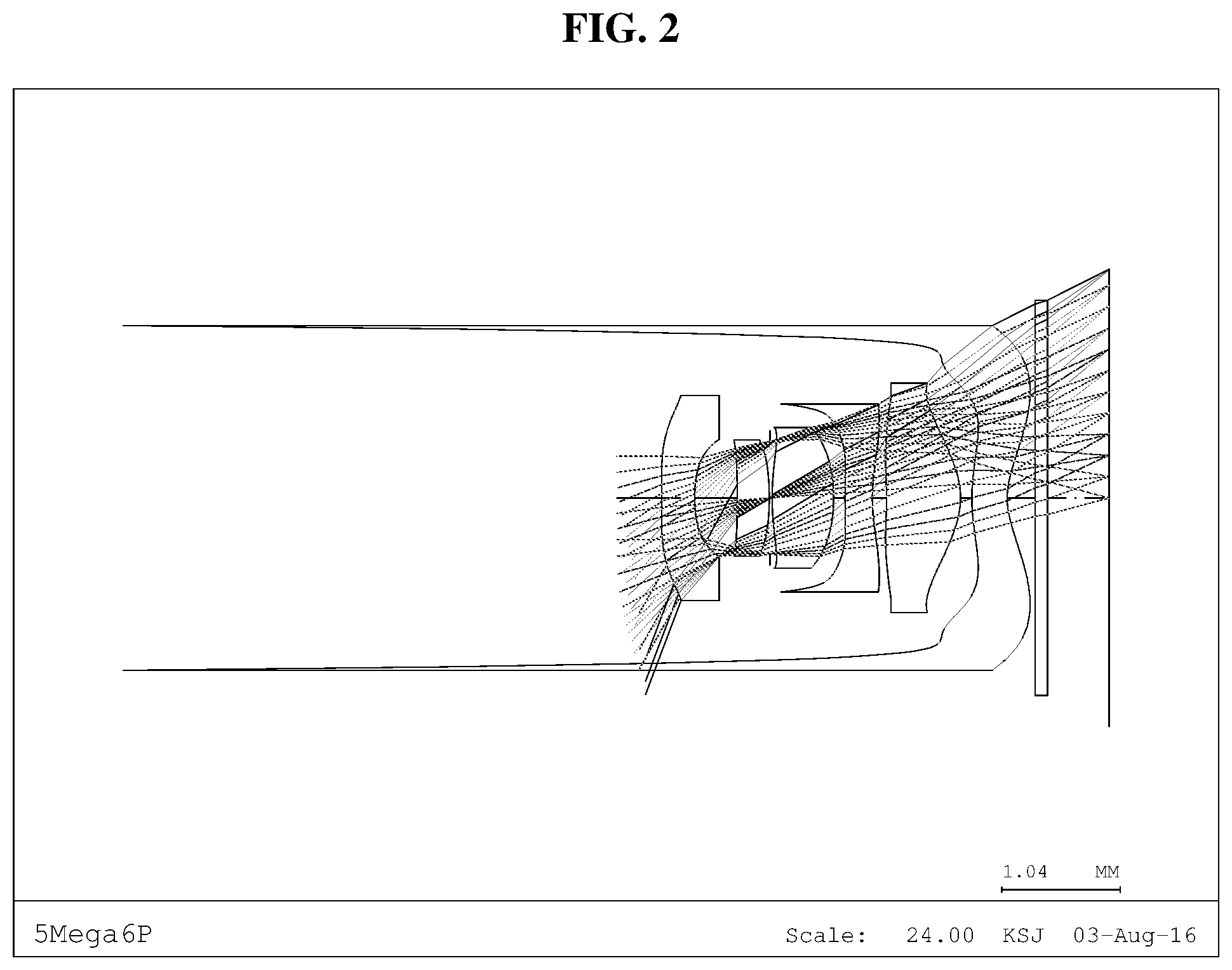
Hereinafter, an optical lens system according to a second embodiment of the present disclosure will be described with reference to FIG. 2.
FIG. 2 is a view illustrating a configuration of an optical lens system according to an embodiment of the present disclosure.
The following table shows optical characteristics of the optical lens system according to the second embodiment of the present disclosure illustrated in FIG. 2.
TABLE-US-00004 TABLE 4 Component r d N f V First lens S11* -10.4623 0.2907 1.5340 -2.3046 55.8559 (L1) S12* 1.4083 0.3746 Second lens S21* -5.4394 0.2803 1.5465 6.2751 56.0928 (L2) S22* -2.1416 0.0049 Aperture S Infinity 0.0201 Third lens S31* 2.2204 0.5400 1.5465 1.6528 56.0928 (L3) S32* -1.3918 0.1000 Fourth lens S31* 3.6368 0.2400 1.6574 -4.1334 21.4744 (L4) S32* 1.5146 0.1244 Fifth lens S51* -3.7041 0.6500 1.5465 1.3378 56.0928 (L5) S52* -0.6485 0.1000 Sixth lens S61* 1.4867 0.3100 1.6455 -1.8358 23.5165 (L6) S62* 0.6055 0.2450 Focal Length(F) 1.4067 Fno 1.9800 CRA(MAX) 34.0061 TTL 3.9300 DFOV 120.0 In the above table, * on the lens surface indicates that the corresponding lens surface is aspheric. In the above table, r is a radius of curvature of the corresponding lens surface, d is a thickness of the corresponding lens on the optical axis when the corresponding lens surface is the object-side surface, or a distance between an exit surface of the corresponding lens to a next component (lens, aperture S, or filter) when the corresponding lens surface is a sensor-side surface. Thus, d of S22 refers to a distance between the sensor-side surface S22 of the second lens L2 and the aperture S located between the second lens L2 and the third lens L3. Also, d of S62 refers to a distance between the sensor-side surface S62 of the sixth lens L6 and a filter located on a rear side of the sixth lens L6. N is a refractive index of the corresponding lens, f is a focal length of the corresponding lens, and V is the Abbe number of the corresponding lens. Here, a distance unit of r, d, and f is mm.
The focal length F is a focal length of the entire optical lens system, CRA is a maximum value of the chief ray angle of the optical lens system, TTL is a total track length of the optical lens system, and, specifically, a distance on the optical axis from the object-side surface S11 of the first lens L1 to the sensor IS, and DFOV is an angle of view of the optical lens system in the diagonal direction. Here, a unit of F and TTL is mm, and an angle of CRA and DFOV is degree.
The aspheric surfaces of the lens surfaces of the optical lens system according to the second embodiment of the present disclosure illustrated in FIG. 2 satisfies the following aspheric surface equation.
.function..times..times..times..times..times..times..times..times..times.- <> ##EQU00002##
Here, z denotes a distance from an apex of a lens in an optical axis direction, and y denotes a distance to a direction perpendicular to the optical axis. R denotes a radius of curvature at the apex of the lens, and K denotes a conic constant. A.sub.2 to A.sub.12 denote aspheric surface coefficients, respectively.
The following table is a table regarding the aspheric surface coefficients of the aspheric surfaces of the optical lens system according to the second embodiment of the present disclosure illustrated in FIG. 2.
TABLE-US-00005 TABLE 5 K A2 A4 A6 A8 A10 A12 S11 79.7597 0.9247 -1.5398 2.2304 -1.9774 0.4752 0.1366 S12 4.1656 1.4744 0.7865 -12.3596 77.1424 -104.1041 -64.4262 S21 89.5524 0.1507 -1.0051 7.2134 -68.4983 294.7238 -473.0470 S22 7.4141 0.1356 -6.8708 50.3921 -224.6766 547.6092 -563.7115 S31 -10.9074 0.3414 -6.6936 49.2324 -224.8519 552.1896 -577.6610 S32 3.1002 -0.3378 0.6956 -0.9107 -6.1920 30.5764 -34.8779 S41 2.5841 -1.1934 0.2269 3.2845 -18.6004 56.5935 -60.1168 S42 1.0995 -0.6176 -0.0253 1.6043 -5.3225 8.7383 -5.5099 S51 15.3891 0.7080 -0.5591 -1.1182 3.2463 -2.9957 1.0962 S52 -0.9238 1.0525 -1.9917 3.3908 -3.2766 1.7025 -0.3525 S61 -29.1487 0.1778 -1.5273 2.9688 -3.7867 2.4813 -0.5997 S62 -5.6576 -0.2074 0.1029 -0.0819 0.0436 -0.0150 0.0023
Referring to FIG. 2 and the above two tables, each lens of the optical lens system according to the second embodiment of the present disclosure satisfies the above-described characteristics.
The following table shows calculation of the values of the Conditional Expression 1 to Conditional Expression 6 described above in the optical lens system of the present embodiment.
TABLE-US-00006 TABLE 6 Target value Target of second Conditional Expression value embodiment Conditional -1.4 < tan.theta./f < -1.1 tan.theta./f -1.2313 Expression 1 Conditional 4.0 < TTL/BFL < 6.0 TTL/BFL 4.3911 Expression 2 Conditional -1.7 < f1/f < -1.4 f1/f -1.6383 Expression 3 Conditional 50 < (V1 + V2)/2 < 60 (V1 + 56.0928 Expression 4 V2)/2 Conditional 30.0deg < CRA(MAX) < CRA 34.0061 Expression 5 35.0deg (MAX) Conditional 0.2 < FSL/TTL < 0.3 FSL/TTL 0.2419 Expression 6
As illustrated in the above table, it can be seen that the optical lens system of the second embodiment of the present disclosure satisfies all of Conditional Expression 1 to Conditional Expression 6.
Hereinafter, an optical lens system according to a third embodiment of the present disclosure will be described with reference to FIG. 3.
FIG. 3 is a view illustrating a configuration of an optical lens system according to an embodiment of the present disclosure.
The following table shows optical characteristics of the optical lens system according to the third embodiment of the present disclosure illustrated in FIG. 3.
TABLE-US-00007 TABLE 7 Component r d N f V First lens ) S11* -10.6473 0.2800 1.5340 -2.3608 55.8559 (L1 S12* 1.4431 0.3579 Second lens S21* -5.8246 0.2779 1.5465 6.4988 56.0928 (L2) S22* -2.2435 0.0067 Aperture S Infinity 0.0096 Third lens S31* 2.2748 0.5341 1.5465 1.6711 56.0928 (L3) S32* -1.3992 0.1000 Fourth lens S31* 3.8787 0.2500 1.6574 -4.1509 21.4744 (L4) S32* 1.5609 0.1068 Fifth lens S51* -3.7315 0.6921 1.5465 1.2963 56.0928 (L5) S52* -0.6344 0.1000 Sixth lens S61* 1.4857 0.3100 1.6455 -1.7690 23.5165 (L6) S62* 0.5928 0.2550 Focal Length(F) 1.4268 Fno 1.9800 CRA(MAX) 33.5000 TTL 3.9300 DFOV 120.0 In the above table, * on the lens surface indicates that the corresponding lens surface is aspheric. In the above table, r is a radius of curvature of the corresponding lens surface, d is a thickness of the corresponding lens on the optical axis when the corresponding lens surface is the object-side surface, or a distance between an exit surface of the corresponding lens to a next component (lens, aperture S, or filter) when the corresponding lens surface is a sensor-side surface. Thus, d of S22 refers to a distance between the sensor-side surface S22 of the second lens L2 and the aperture S located between the second lens L2 and the third lens L3. Also, d of S62 refers to a distance between the sensor-side surface S62 of the sixth lens L6 and a filter located on a rear side of the sixth lens L6. N is a refractive index of the corresponding lens, f is a focal length of the corresponding lens, and V is the Abbe number of the corresponding lens. Here, a distance unit of r, d, and f is mm.
The focal length F is a focal length of the entire optical lens system, CRA is a maximum value of the chief ray angle of the optical lens system, TTL is a total track length of the optical lens system, and, specifically, a distance on the optical axis from the object-side surface S11 of the first lens L1 to the sensor IS, and DFOV is an angle of view of the optical lens system in the diagonal direction. Here, a unit of F and TTL is mm, and an angle of CRA and DFOV is degree.
The aspheric surfaces of the lens surfaces of the optical lens system according to the third embodiment of the present disclosure illustrated in FIG. 3 satisfies the following aspheric surface equation.
.function..times..times..times..times..times..times..times..times..times.- <> ##EQU00003##
Here, z denotes a distance from an apex of a lens in an optical axis direction, and y denotes a distance to a direction perpendicular to the optical axis. R denotes a radius of curvature at the apex of the lens, and K denotes a conic constant. A.sub.2 to A.sub.12 denote aspheric surface coefficients, respectively.
The following table is a table regarding the aspheric surface coefficients of the aspheric surfaces of the optical lens system according to the third embodiment of the present disclosure illustrated in FIG. 3.
TABLE-US-00008 TABLE 8 K A2 A4 A6 A8 A10 A12 S11 79.7597 0.9435 -1.6126 2.3962 -2.2033 0.5417 0.1752 S12 4.5724 1.4910 0.7094 -13.8033 96.7733 -197.2828 93.2161 S21 99.0000 0.1507 -1.0051 7.2134 -68.4983 294.7238 -473.0470 S22 7.8248 0.1911 -8.3799 63.8263 -288.1291 702.8642 -720.4247 S31 -10.9074 0.4015 -7.9098 60.4833 -274.3843 663.8063 -674.1102 S32 3.0562 -0.3755 1.0932 -1.7275 -8.1147 41.5280 -48.0062 S41 2.5841 -1.2663 0.7258 2.3696 -19.9269 61.4991 -63.4491 S42 1.1062 -0.6384 0.3601 0.3663 -3.5761 7.2819 -4.7727 S51 15.2312 0.7012 -0.4333 -1.7096 4.0617 -3.2191 0.9294 S52 -0.9110 1.0605 -2.1130 3.7178 -4.0138 2.6114 -0.7457 S61 -29.1487 0.1870 -1.5486 2.9084 -3.5846 2.2463 -0.5135 S62 -5.4719 -0.1914 0.0529 -0.0151 -0.0042 0.0028 -0.0006
Referring to FIG. 3 and the above two tables, each lens of the optical lens system according to the third embodiment of the present disclosure satisfies the above-described characteristics.
The following table shows calculation of the values of the Conditional Expression 1 to Conditional Expression 6 described above in the optical lens system of the present embodiment.
TABLE-US-00009 TABLE 9 Target value Target of third Conditional Expression value embodiment Conditional -1.4 < tan.theta./f < -1.1 tan.theta./f -1.2139 Expression 1 Conditional 4.0 < TTL/BFL < 6.0 TTL/BFL 4.3425 Expression 2 Conditional -1.7 < f1/f < -1.4 f1/f -1.6546 Expression 3 Conditional 50 < (V1 + V2)/2 < 60 (V1 + 56.0928 Expression 4 V2)/2 Conditional 30.0deg < CRA(MAX) < CRA 33.5000 Expression 5 35.0deg (MAX) Conditional 0.2 < FSL/TTL < 0.3 FSL/TTL 0.2347 Expression 6
As illustrated in the above table, it can be seen that the optical lens system of the third embodiment of the present disclosure satisfies all of Conditional Expression 1 to Conditional Expression 6.
Hereinafter, an optical lens system according to a fourth embodiment of the present disclosure will be described with reference to FIG. 4.
FIG. 4 is a view illustrating a configuration of an optical lens system according to an embodiment of the present disclosure.
The following table shows optical characteristics of the optical lens system according to the fourth embodiment of the present disclosure illustrated in FIG. 4.
TABLE-US-00010 TABLE 10 Component r d N f V First lens S11* 13.2691 0.2940 1.5340 -2.0987 55.8559 (L1) S12* 1.0255 0.4287 Second lens S21* 7.7431 0.2804 1.5465 3.7927 56.0928 (L2) S22* -2.7942 0.0100 Aperture S Infinity Infinity 0.0283 Third lens S31* 2.7426 0.4921 1.5465 1.7062 56.0928 (L3) S32* -1.3231 0.1000 Fourth lens S31* 3.0078 0.2500 1.6574 -4.0956 21.4744 (L4) S32* 1.3739 0.1814 Fifth lens S51* -2.8358 0.6500 1.5465 1.2903 56.0928 (L5) S52* -0.6105 0.1000 Sixth lens S61* 1.4439 0.3000 1.6455 -1.6588 23.5165 (L6) S62* 0.5647 0.2550 Focal Length(F) 1.3910 Fno 1.9800 CRA(MAX) 33.6612 TTL 3.9200 DFOV 120.6000 In the above table, * on the lens surface indicates that the corresponding lens surface is aspheric. In the above table, r is a radius of curvature of the corresponding lens surface, d is a thickness of the corresponding lens on the optical axis when the corresponding lens surface is the object-side surface, or a distance between an exit surface of the corresponding lens to a next component (lens, aperture S, or filter) when the corresponding lens surface is a sensor-side surface. Thus, d of S22 refers to a distance between the sensor-side surface S22 of the second lens L2 and the aperture S located between the second lens L2 and the third lens L3. Also, d of S62 refers to a distance between the sensor-side surface S62 of the sixth lens L6 and a filter located on a rear side of the sixth lens L6. N is a refractive index of the corresponding lens, f is a focal length of the corresponding lens, and V is the Abbe number of the corresponding lens. Here, a distance unit of r, d, and f is mm.
The focal length F is a focal length of the entire optical lens system, CRA is a maximum value of the chief ray angle of the optical lens system, TTL is a total track length of the optical lens system, and, specifically, a distance on the optical axis from the object-side surface S11 of the first lens L1 to the sensor IS, and DFOV is an angle of view of the optical lens system in the diagonal direction. Here, a unit of F and TTL is mm, and an angle of CRA and DFOV is degree.
The aspheric surfaces of the lens surfaces of the optical lens system according to the fourth embodiment of the present disclosure illustrated in FIG. 4 satisfies the following aspheric surface equation.
.function..times..times..times..times..times..times..times..times..times.- <> ##EQU00004##
Here, z denotes a distance from an apex of a lens in an optical axis direction, and y denotes a distance to a direction perpendicular to the optical axis. R denotes a radius of curvature at the apex of the lens, and K denotes a conic constant. A.sub.2 to A.sub.12 denote aspheric surface coefficients, respectively.
The following table is a table regarding the aspheric surface coefficients of the aspheric surfaces of the optical lens system according to the fourth embodiment of the present disclosure illustrated in FIG. 4.
TABLE-US-00011 TABLE 11 K A.sub.2 A.sub.4 A.sub.6 A.sub.8 A.sub.10 A.sub.12 S11 79.7597 0.4364 -0.5851 0.5023 -0.3315 0.0985 0.0000 S12 1.0585 0.7749 0.4016 -0.7812 -6.7496 54.0967 -88.9830 S21 99.0000 -0.1295 0.6667 -10.3445 50.5502 -134.7000 139.2732 S22 1.3375 0.4765 -6.0989 34.6891 -128.2281 259.9933 -198.2307 S31 10.3758 0.6119 -6.5676 38.9336 -159.1419 359.8946 -349.4029 S32 2.8251 -0.6955 3.2721 -9.7723 17.1528 -11.0797 0.2838 S41 2.4246 -1.6133 1.9718 -0.9122 -12.8692 49.7979 -53.7428 S42 1.0834 -0.7537 0.1200 2.8858 -9.6489 13.9858 -8.1411 S51 9.7082 0.5531 -0.5708 0.5006 -0.2154 -0.1125 0.3401 S52 -0.8839 0.9743 -1.9907 3.5704 -3.9464 2.6165 -0.7040 S61 -29.1487 0.0522 -1.0440 1.9564 -2.2465 1.3069 -0.2813 S62 -5.3262 -0.2044 0.0899 -0.0186 -0.0237 0.0153 -0.0028
Referring to FIG. 4 and the above two tables, each lens of the optical lens system according to the fourth embodiment of the present disclosure satisfies the above-described characteristics.
The following table shows calculation of the values of the Conditional Expression 1 to Conditional Expression 6 described above in the optical lens system of the present embodiment.
TABLE-US-00012 TABLE 12 Target value Target of fourth Conditional Expression value embodiment Conditional -1.4 < tan.theta./f < -1.1 tan.theta./f -1.2156 Expression 1 Conditional 4.0 < TTL/BFL < 6.0 TTL/BFL 4.8696 Expression 2 Conditional -1.7 < f1/f < -1.4 f1/f -1.5088 Expression 3 Conditional 50 < (V1 + V2)/2 < 60 (V1 + 56.0928 Expression 4 V2)/2 Conditional 30.0deg < CRA(MAX) < CRA 33.6612 Expression 5 35.0deg (MAX) Conditional 0.2 < FSL/TTL < 0.3 FSL/TTL 0.2585 Expression 6
As illustrated in the above table, it can be seen that the optical lens system of the fourth embodiment of the present disclosure satisfies all of Conditional Expression 1 to Conditional Expression 6.
Embodiments of the optical lens system of the present disclosure have been described. The present disclosure is not limited to the above-described embodiments and the accompanying drawings and various modifications and changes may be made by those skilled in the art to which the present disclosure pertains. Therefore, the scope of the present disclosure should be determined by the claims and equivalents of the claims.
* * * * *
D00000
D00001
D00002
D00003
D00004
M00001
M00002
M00003
M00004
XML
uspto.report is an independent third-party trademark research tool that is not affiliated, endorsed, or sponsored by the United States Patent and Trademark Office (USPTO) or any other governmental organization. The information provided by uspto.report is based on publicly available data at the time of writing and is intended for informational purposes only.
While we strive to provide accurate and up-to-date information, we do not guarantee the accuracy, completeness, reliability, or suitability of the information displayed on this site. The use of this site is at your own risk. Any reliance you place on such information is therefore strictly at your own risk.
All official trademark data, including owner information, should be verified by visiting the official USPTO website at www.uspto.gov. This site is not intended to replace professional legal advice and should not be used as a substitute for consulting with a legal professional who is knowledgeable about trademark law.