Mobile drive unit having a split chassis
Pajevic , et al. May 11, 2
U.S. patent number 11,001,117 [Application Number 15/934,507] was granted by the patent office on 2021-05-11 for mobile drive unit having a split chassis. This patent grant is currently assigned to Amazon Technologies, Inc.. The grantee listed for this patent is Amazon Technologies, Inc.. Invention is credited to Peter Thomas Colantonio, Dragan Pajevic.

| United States Patent | 11,001,117 |
| Pajevic , et al. | May 11, 2021 |
Mobile drive unit having a split chassis
Abstract
A mobile drive unit includes a pivot between the front chassis unit and the rear chassis unit, thereby diminishing the total height of the unit.
| Inventors: | Pajevic; Dragan (Arlington, MA), Colantonio; Peter Thomas (North Andover, MA) | ||||||||||
|---|---|---|---|---|---|---|---|---|---|---|---|
| Applicant: |
|
||||||||||
| Assignee: | Amazon Technologies, Inc.
(Seattle, WA) |
||||||||||
| Family ID: | 1000005547586 | ||||||||||
| Appl. No.: | 15/934,507 | ||||||||||
| Filed: | March 23, 2018 |
Prior Publication Data
| Document Identifier | Publication Date | |
|---|---|---|
| US 20190291528 A1 | Sep 26, 2019 | |
| Current U.S. Class: | 1/1 |
| Current CPC Class: | G05D 1/0227 (20130101); B62D 61/04 (20130101); B60P 1/6445 (20130101); B62D 21/18 (20130101); B60D 1/46 (20130101); B60G 17/0195 (20130101); B60G 7/003 (20130101); B60G 2800/91 (20130101); B60G 2206/011 (20130101) |
| Current International Class: | B60G 17/0195 (20060101); B60P 1/64 (20060101); G05D 1/02 (20200101); B60G 7/00 (20060101); B62D 21/18 (20060101); B62D 61/04 (20060101); B60D 1/46 (20060101) |
References Cited [Referenced By]
U.S. Patent Documents
| 3520378 | July 1970 | Slay |
| 3709313 | January 1973 | James |
| 4128137 | December 1978 | Booth |
| 4245847 | January 1981 | Knott |
| 4310167 | January 1982 | McLaurin |
| 4515235 | May 1985 | Yamamoto |
| 5036935 | August 1991 | Kohara |
| 5435404 | July 1995 | Garin, III |
| 5630607 | May 1997 | Yancer |
| 5901805 | May 1999 | Murakami |
| 6196343 | March 2001 | Strautnieks |
| 6206119 | March 2001 | Wu |
| 6454286 | September 2002 | Hosino |
| 6494474 | December 2002 | Kramer, Jr. |
| 7293801 | November 2007 | Bertrand |
| 7735591 | June 2010 | Puskar-Pasewicz |
| 7775307 | August 2010 | Cheng |
| 7828310 | November 2010 | Vreeswijk |
| 8113531 | February 2012 | Zhou |
| 8918202 | December 2014 | Kawano |
| 9152149 | October 2015 | Palamarchuk |
| 9308143 | April 2016 | Bekoscke |
| 2003/0020261 | January 2003 | Perelli |
| 2003/0106731 | June 2003 | Marino |
| 2004/0093116 | May 2004 | Mountz |
| 2005/0077715 | April 2005 | Mulhern |
| 2007/0018418 | January 2007 | Huang |
| 2007/0080510 | April 2007 | Ji |
| 2014/0228999 | August 2014 | D'Andrea |
| 2017/0015168 | January 2017 | Estier |
| 2017/0340942 | November 2017 | Connell |
| 2018/0072355 | March 2018 | Sakashita |
| 2019/0155296 | May 2019 | Moore |
| 2019/0161274 | May 2019 | Paschall, II |
| 2019/0291956 | September 2019 | Pajevic |
| 2019/0294175 | September 2019 | Pajevic |
| 3281848 | Feb 2018 | EP | |||
| 2342197 | Sep 1977 | FR | |||
| 2372485 | Aug 2002 | GB | |||
| 2012-228996 | Nov 2012 | JP | |||
Other References
|
International Patent Application No. PCT/US2019/023752; Int'l Search Report and the Written Opinion; dated Jun. 21, 2019; 14 pages. cited by applicant . International Patent Application No. PCT/US2019/023752; Int'l Preliminary Report on Patentability; dated Oct. 8, 2020; 8 pages. cited by applicant. |
Primary Examiner: Ilan; Ruth
Assistant Examiner: Williams; Maurice L
Attorney, Agent or Firm: BakerHostetler
Claims
What is claimed is:
1. A mobile drive unit chassis assembly for traversing a floor, the chassis assembly comprising: a front chassis unit including a pair of mid-chassis drive wheel assemblies and a front caster assembly mounted to a front chassis base; a rear chassis unit including a rear caster assembly mounted on a rear chassis base, a pivotal connection between the rear chassis base and the front chassis base; each one of the front caster assembly and the rear caster assembly being asymmetrically offset from a driving-direction centerline of the chassis assembly; and whereby the pivotable connection enhances floor contact of the drive wheels and the front and rear caster assemblies when traveling over an uneven floor.
2. A mobile drive unit chassis assembly for traversing a floor, the chassis assembly comprising: a first chassis unit including a first chassis base, a pair of motorized drive wheel assemblies coupled to opposing sides of the first chassis base, a first load mount, and a caster assembly mounted on the first chassis base; the first load mount being adapted for receiving a portion of a load; a second chassis unit including a second chassis base, a second load mount, and a caster assembly mounted on the second chassis base; the second load mount being adapted for receiving another portion of the load; the second chassis base and the first chassis base coupled together by a pivotable connection, the pivotal connection defining a pivotal axis; and a spring assembly spanning across the pivotal axis and coupled between the first chassis base and the second chassis base, the spring assembly adapted for applying a biasing force to each one of the caster assembly of the first chassis unit and the caster assembly of the second chassis unit; wherein each one of a first caster wheel of the first caster assembly and a second caster wheel of the second caster assembly is asymmetrically offset from a line parallel to a direction of forward motion of the chassis assembly, the first and second caster wheels being configured such that the first and second caster wheels are spaced apart from a floor fiducial marker when the mobile drive unit passes over the floor fiducial marker in a straight line.
3. The chassis assembly of claim 2 wherein the line parallel to the direction of forward motion of the chassis assembly is a driving-direction centerline of the chassis assembly.
4. The chassis assembly of claim 3 wherein the first chassis is a front chassis unit and the second chassis is a rear chassis unit, and the mobile drive unit is configured to carry a pod.
5. The chassis assembly of claim 4 wherein the first caster assembly is a front caster assembly, the first caster wheel is a front caster wheel, the second caster assembly is a rear caster assembly, and the second caster wheel is a rear caster wheel and wherein spring assembly is adapted to provide a biasing force applying a downward force to each one of the front caster wheel and the rear caster wheel.
6. The chassis assembly of claim 5 wherein the front chassis unit has a single-piece base that is a casting, and the rear chassis unit has a single-piece base that is a casting, and the rear chassis unit includes a ballast coupled to a rear end thereof.
7. The chassis assembly of claim 4 further comprising a component mounted to the rear chassis unit, the component extending upwardly from the rear chassis unit and defining the highest vertical extend on the rear chassis unit.
8. The chassis assembly of claim 7 wherein the component is a battery that is electrically connected to the motorized drive wheels for providing power to the motorized drive wheels.
9. The chassis assembly of claim 7 further comprising a top structure that extends over at least portions of the front chassis and rear chassis, a vertical dimension between the top structure and the component defining a gap G, the pivotable connection enabling the rear chassis unit to pivot relative to the front chassis unit to at least partially maintain the gap G.
10. The chassis assembly of claim 9 wherein the first load mount is a front load mount and the second load mount is a rear load mount, the front chassis includes the first load mount and the rear chassis includes the second load mount, and wherein the load is load from the top structure.
11. The chassis assembly of claim 10 wherein the load is transmitted from the top structure to the front and rear load mounts by a support structure.
12. The chassis assembly of claim 4 including a cover, the covering including a front cover unit affixed to the front chassis unit and a rear cover unit affixed to the rear chassis unit, the front cover unit and rear cover unit being spaced apart by a gap that enables pivoting of the front chassis unit relative to the rear chassis unit.
13. The chassis assembly of claim 2 wherein the spring assembly includes a bracket that is affixed to one of the first chassis unit and the second chassis unit and a spring that applies a spring force to the other one of the first caster assembly and the second caster assembly.
14. A method of transporting a load via a mobile drive unit, comprising the steps of: (a) the mobile drive unit of claim 2 receiving a drive signal; (b) in response to the receiving step (a), powering the pair of motorized drive wheels to drive the mobile drive unit in a forward direction over the floor fiducial marker such that each one of the caster assembly of the first chassis unit and the caster assembly of the second chassis unit is asymmetrically offset relative to the floor marker; and (c) upon encountering a floor irregularity, the first chassis unit of the mobile drive unit pivoting relative to the second chassis unit of the mobile drive unit.
15. The method of claim 14 wherein the step (b) includes driving the mobile drive unit such that the caster assembly of the first chassis unit is on a first side of a mobile drive unit centerline and the caster assembly of the second chassis unit is on a second, opposing side of the mobile drive unit centerline.
16. The method of claim 15 wherein the mobile drive unit centerline is co-incident with the forward direction.
17. The method of claim 15 further comprising the step of biasing the first chassis unit relative to the second chassis unit to apply a force to each one of the caster assembly of the first chassis unit and the caster assembly of the second chassis unit via a spring assembly that spans a pivotal axis between the first chassis unit and the second chassis unit.
18. The method of claim 15 further comprising loading the mobile drive unit with a pod holding products.
19. The method of claim 15 wherein the driving step (c) includes a front cover unit of the front chassis unit pivoting relative to a rear cover unit of the rear chassis unit.
Description
BACKGROUND
The invention relates to robotic devices and methods, and more particularly to mobile drive units.
Movement of products in a modern warehouse environment, such as a fulfillment center, occurs on a vast scale. One means for managing order fulfillment is to house the products in free-standing shelving units, referred to as pods, and to transport the pods using mobile drive units. Some mobile drive units are self-powered robotic devices that travel on the floor of the warehouse guided by fiducial markers in or on the floor. The mobile drive units move beneath desired pods, lifts the pod from the floor, and transport the pods to desired locations.
One type of mobile drive unit that has been in commercial use employs a one-piece chassis having a pair of motorized midwheels, a pair of front caster wheels, and a pair of rear caster wheels, which are attached to the chassis by a suspension arm. For each of the front caster wheels and the rear caster wheels in some prior art units, the left and right caster wheels are mounted on a common shaft and spaced apart such that the left and right wheels straddle the longitudinal centerline of the mobile drive unit.
Increasing storage density enables fulfillment centers to increase the quantity, and potentially diversity of products stored, which typically leads to an enhanced consumer experience. The total height of the mobile drive unit is important variable in effectively managing storage density. Specifically, as the height of the mobile drive unit uses vertical space that could otherwise be used by pods to hold products. Further, it is common for warehouse concrete floor to have irregularities, such as expansion joints or dips inherent in building process or caused by floor wear or damage.
BRIEF DESCRIPTION OF THE DRAWINGS
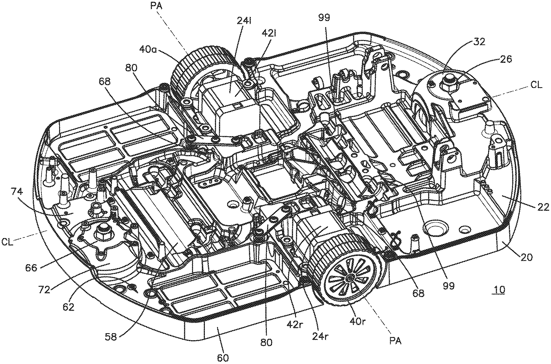
FIG. 1 is a perspective view illustrating a hinged chassis configuration;
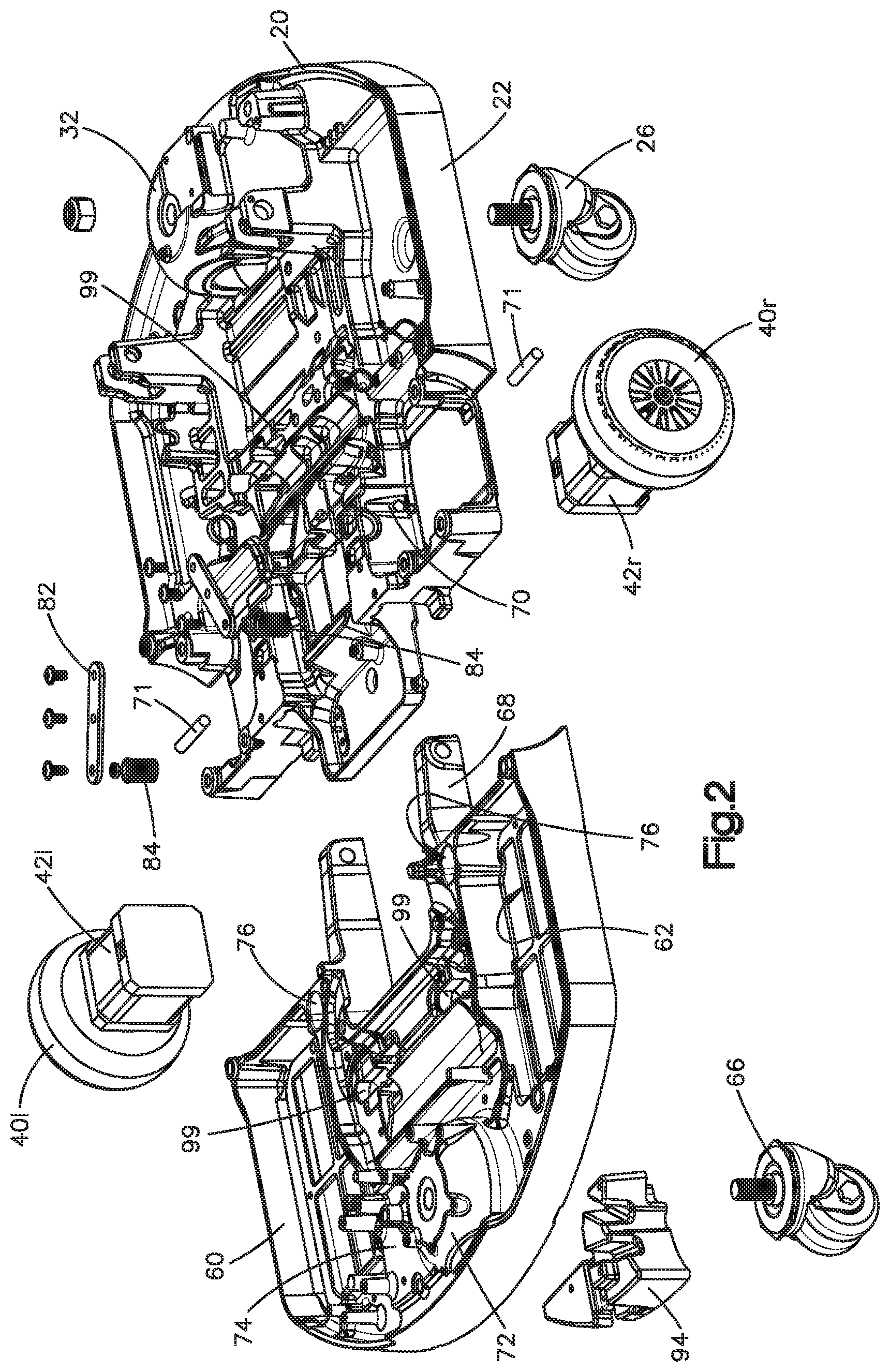
FIG. 2 is an exploded view of the chassis of FIG. 1;
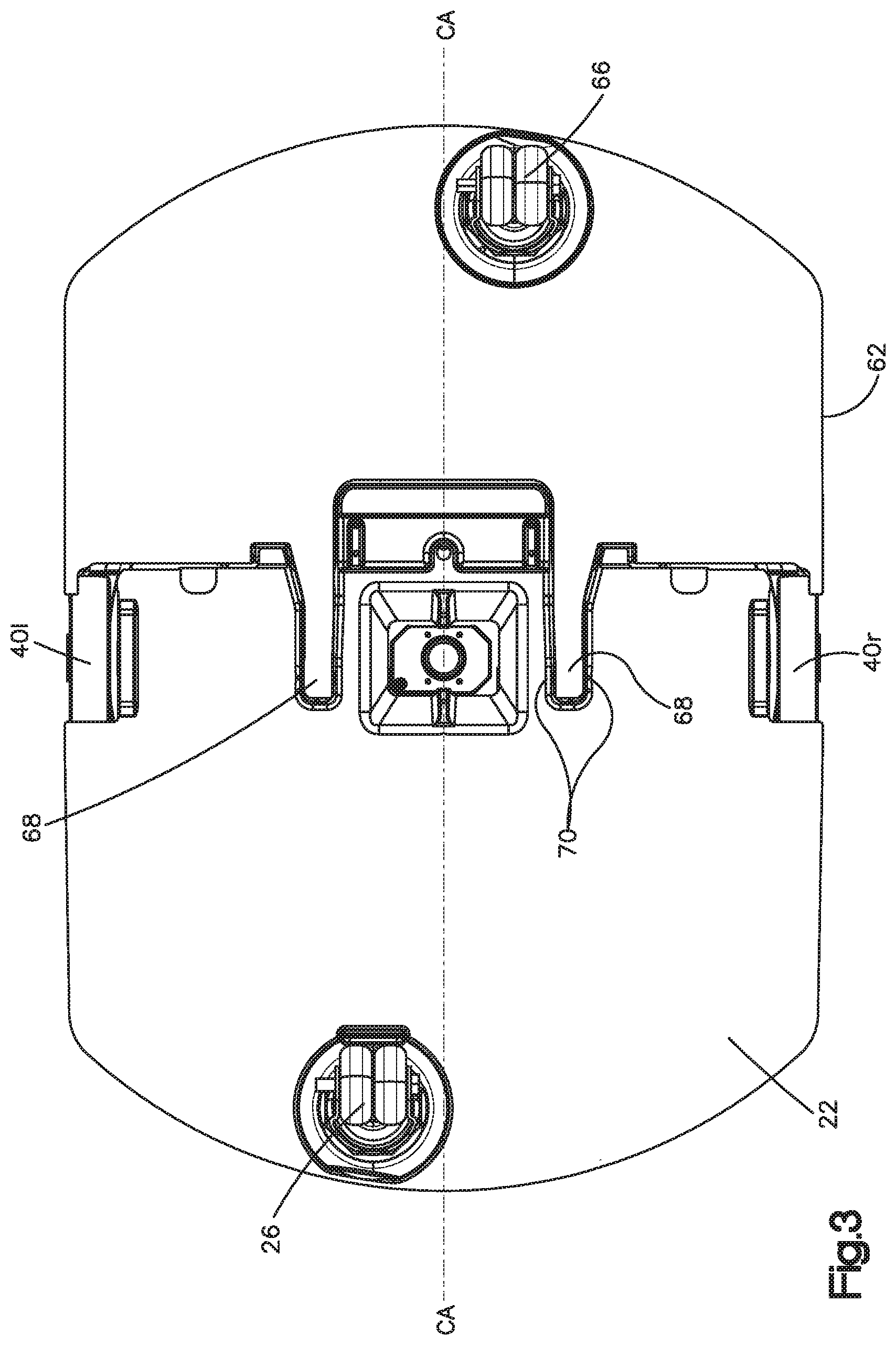
FIG. 3 is a bottom view of the chassis of FIG. 1;
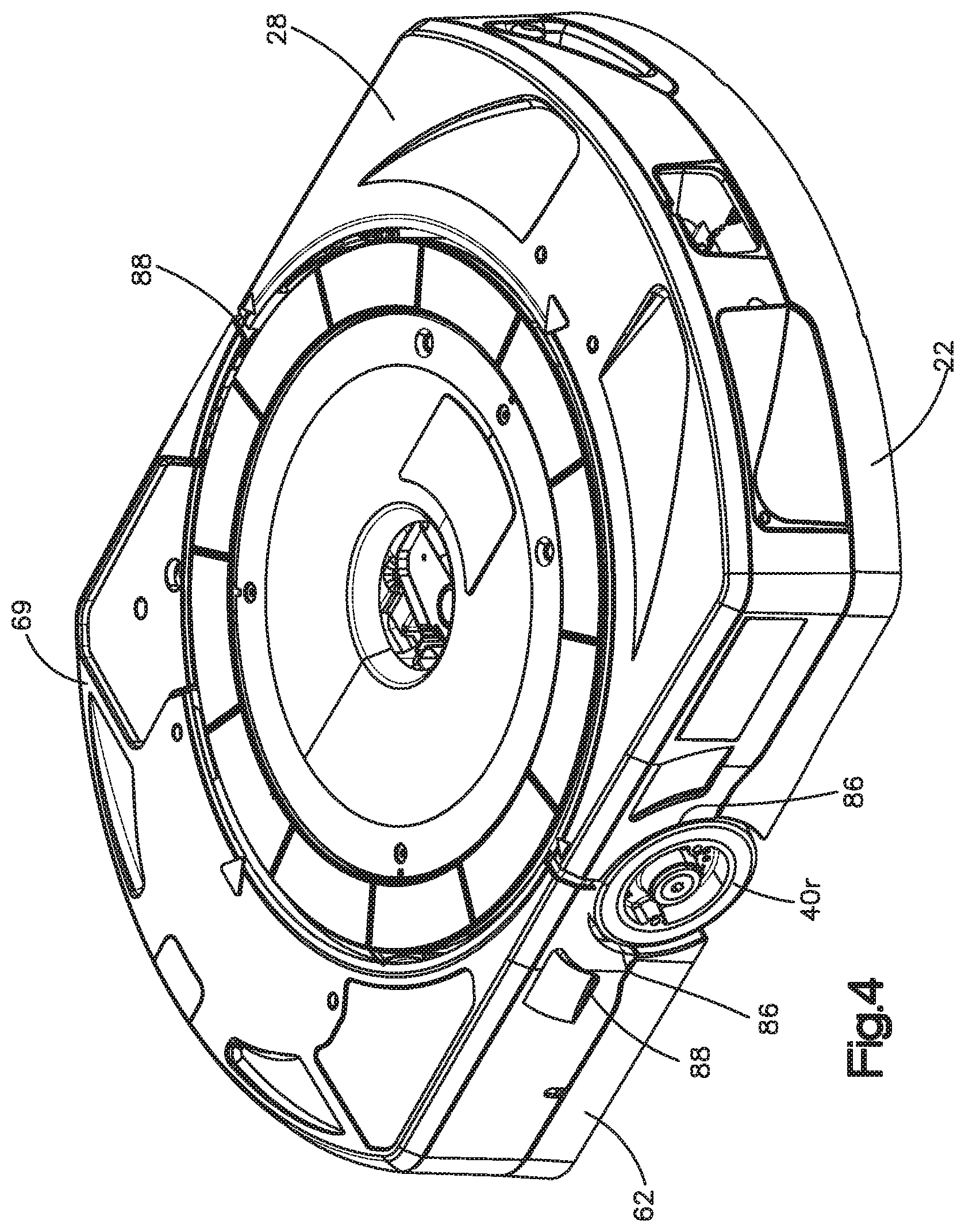
FIG. 4 is a perspective view of a chassis including a cover;
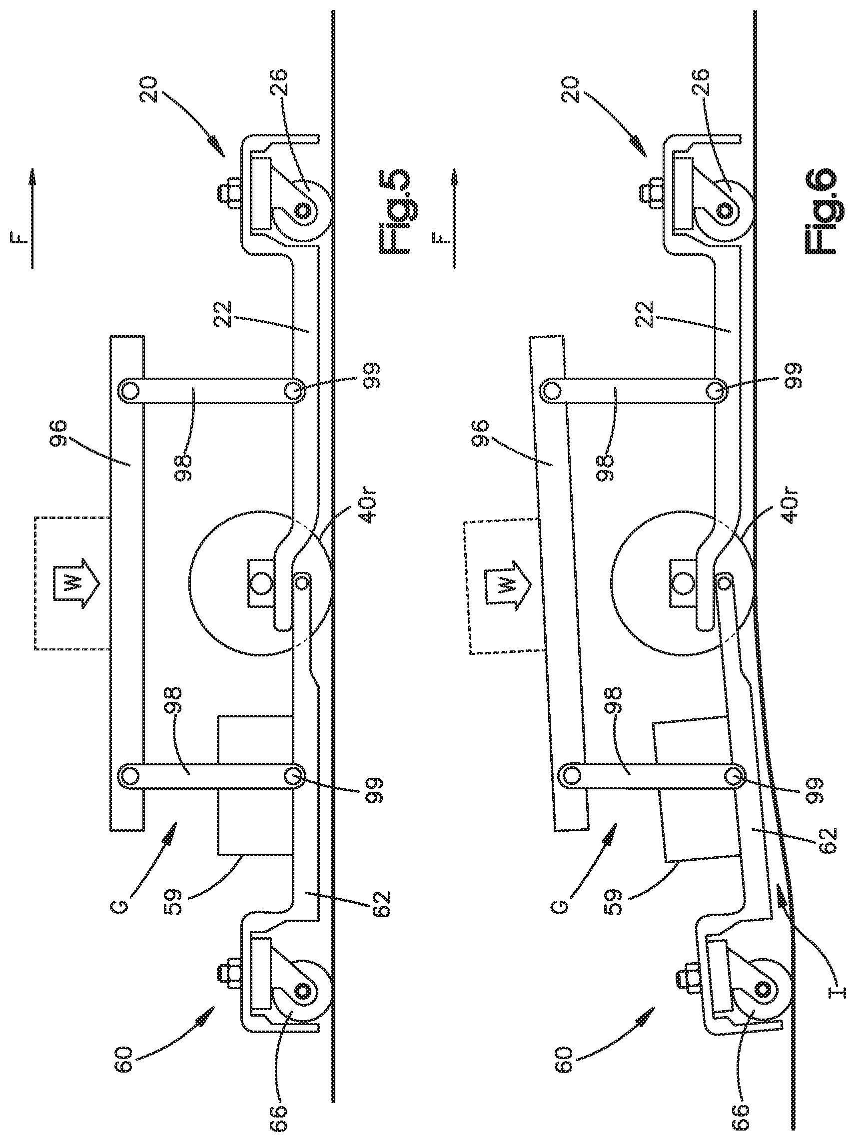
FIG. 5 is a schematic view of a cross section of the chassis of FIG. 1; and
FIG. 6 is another view of the chassis of FIG. 5 illustrating operation of the chassis upon encountering an irregularity in the floor.
DETAILED DESCRIPTION OF ILLUSTRATIVE EMBODIMENTS
The following disclosure relates to solutions to problems arising from or relating (at least in part) to achieving a short mobile drive unit. One type of exemplary mobile drive unit employs a one-piece chassis having a pair of motorized midwheels, a pair of front caster wheels, and a pair of rear caster wheels, which are attached to the chassis by a suspension arm. The front caster wheels and rear caster wheels are aligned along a longitudinal centerline of the mobile drive unit. Both the front and rear have a pair of casters that are closely connected by a common arm that may cause instability or rocking during operation.
A mobile drive unit 8 configured for use in inventory fulfillment includes a chassis. The chassis described herein includes a front chassis unit and a rear chassis unit that are hinged together such that upon encountering a floor irregularity, the front and/or rear chassis can move about a pivot. The pivoting feature of the chassis enables the overall height of the mobile drive unit to have a diminished height compared with prior generations of similar mobile drive units.
Referring FIGS. 1-3, a chassis 10 of a mobile drive unit includes a first chassis assembly, such as front chassis assembly or unit 20, and a second chassis assembly, such as rear chassis assembly or unit 60. Front chassis assembly 20 includes a base 22, a pair of motorized wheel assemblies 24L and 24R, and a front caster 26. Base 22 in the embodiment shown in the figures is a one-piece aluminum casting to which the wheel assemblies 24L and 24R and front caster 26 are mounted. Base 22 includes mounts and cut outs for receiving the wheel assemblies 24L and 24R, and includes a recess for mounting front caster 26. Base 22 also includes a pair of pivot mounts 70, as explained more fully below.
Rear chassis assembly 60 includes a base 62 and rear caster 66. Base 62 preferably is a one-piece aluminum casting that includes a recess for mounting rear caster 66 and an underside recess (shown from the top as reference number 74 in FIG. 2) for mounting a ballast 94. Base 62 may also include a mount 58 for batteries. FIG. 3 illustrates aspects of the split chassis and the relationship of the caster wheels, and omits other features, such as ballast 94.
Rear chassis assembly 60 includes a pair of forward-extending arms 68 that engage pivot mounts 70 of front base 22. A pair of pins 71 (FIG. 2) link arms 68 to mounts 70 to enable front base 22 and rear base 62 to pivot relative to each other. Pins 71 define a chassis pivot axis PA (FIG. 1) about which bases 22 and 62 pivot or rotate as needed. Axis PA is horizontal and transverse. Axis PA is also perpendicular to a direction of forward motion, which is illustrated in FIG. 1 by line CL, as in the embodiment shown the direction of forward motion is parallel to the centerline CL of MDU 8. Centerline CL bisects the bases 22 and 62 and is equidistant between the drive wheel assemblies 24L and 24R.
Casters 26 and 66 are mounted to base 22 and 62 (respectively)--the caster shafts extend through the base and are affixed by bolts. Preferably, casters 26 and 66 are conventional, and may include double wheels. Casters 26 and 66 freely pivot about the vertical axis through the shafts and are not driven. Casters 26 and 66 are asymmetrically and laterally offset from centerline CL. In the embodiment shown in the figures, front caster 26 is spaced apart from centerline CL to the left and rear caster 66 is spaced apart from centerline CL to the right. The offset spacing enables the drive unit 8 to pass over a fiducial marker, such as a bar code or 3D code, in the floor without any of the wheels contacting the marker. Thus, the centerline CL of MDU 8 passes directly over a fiducial marker when the unit 8 drives forward.
Each motor assembly 24L and 24R includes a conventional motor 42L and 42R (as will be understood by persons familiar with mobile drive unit technology) and a drive wheel 40L and 40R, respectively. Wheels 40L and 40R are approximately at the midpoint (fore and aft) of mobile drive unit 8. Each wheel 40L and 40R may be driven according to control signals to move the unit 8 forward, or a direction of one of the wheels can be reversed such that the drive unit 8 can rotate in place.
A pair of spring assemblies 80 have the function of transmitting a downward force on each one of the front caster 26 and rear caster 66, and thus spring assemblies 80 diminish the downward force on drive wheels 40L and 40R. Each spring assembly 80 includes a bracket 82 that is affixed to a rear portion of front chassis base 22 and extends rearwardly to a front portion of rear chassis base 62. Spring assembly 80 includes a compression spring 84 that is located in a pocket 76 formed in rear base 62. Compression spring 84 includes an adjusting bolt that enables spring 84 a pre-load force to be set.
Referring to FIG. 4, mobile drive unit 8 can include a front cover 28 that is affixed to front base 22 and a rear cover 69 that is affixed to rear base 62. Each cover 28 and 69 have a cut-out portion that, with the corresponding cut-outs in bases 22 and 62, forms wheel cut-out that wheels 40L/40R extend through. In this regard, wheels 40L and 40R may extend laterally to the outboard sides of the mobile drive unit.
Each one of front base 22 and rear base 62 includes a support structure or mounts 99 for mounting a support structure 98, as explained below and shown schematically in FIGS. 5 and 6. Mounts 99 may have any configuration and supports that connect to mounts 99 may take any configuration, as mounts 99 encompass (without limitation) pivots and fixed structure.
FIG. 5 schematically illustrates front chassis unit 20 and rear chassis unit 60 carrying a load W on a top structure 96. Top structure 96 can be any structure, such as a turntable shown in FIG. 4, or any other structure without limitation. Accordingly, top structure supports 98 may be any configuration and are shown only for illustration, as will be understood and can be implemented by persons familiar with mobile drive unit technology and depending on the particular parameters of the application.
A component, such as a battery pack 59, is mounted to rear base 62 to illustrate the operation of the mobile drive unit 8 (FIGS. 5 and 6). In this regard, component/battery 59 is employed to illustrate the gap between the components of mounted on the rear chassis base 62 of the mobile drive unit 8 and the top structure 96, which gap is required to avoid damage to the components. Thus, FIG. 5 illustrates the unit on a flat surface such that top structure 96 is spaced apart from component 59 to form a gap G.
Upon receiving a drive signal from the controls to drive forward, motors 42L and 42R provide torque to wheels 40L and 40R. Upon encountering an irregularity, such a bump I, as illustrated in FIG. 6, rear chassis unit 60 follows front chassis unit 20 over irregularity I such that rear chassis unit 60 pivots relative to front chassis unit 20. Clearance gap G is maintained.
The pivoting relationship is distinguished from prior mobile drive units, in which component 59 (or the highest vertical component on the rear unit) was affixed to an extension of the front chassis such that encountering the irregularity I shown in FIG. 6 eliminated gap G, enabling the top structure to contact the components. To prevent the contact between the top structure and the components, prior art mobile drive units where configured with a greater gap and therefore an overall greater height compared with the mobile drive unit 8. In this regard, in the embodiment shown, both the highest vertical component mounted and the support structure 98 for the top structure are located on the rear chassis unit base 62.
The structure described herein enables a lower overall height. Prior mobile drive units had a total height of 10 inches or greater. Mobile drive unit 8 has a total height of 7.785 inches.
The mobile drive unit includes controllers, cameras and other sensors, a docking port, a turntable, motors to lift and rotate the turntable, and the other components. A person familiar with mobile drive unit technology will understand how to mount and employ the additional components to the front and rear chassis units disclosed herein according to the particular goals and design of the mobile drive unit application.
The present invention has been described by employing a particular embodiment to illustrate particular features. For merely one non-limiting example, components are referred to as front and rear in order to illustrate the structure and function, but the invention is not limited to the particular front and rear orientations unless expressly stated in the claims. Further, the present invention is not limited to any structure or function, nor is the invention limited to any solution to any problem, described herein unless expressly stated in the claims. Nor is the invention limited in any way to embodying a benefit unless expressly stated in the claims. Rather, the structure and function described herein is merely an illustration, and the claims are intended to receive their full scope.
* * * * *
D00000
D00001
D00002
D00003
D00004
D00005
XML
uspto.report is an independent third-party trademark research tool that is not affiliated, endorsed, or sponsored by the United States Patent and Trademark Office (USPTO) or any other governmental organization. The information provided by uspto.report is based on publicly available data at the time of writing and is intended for informational purposes only.
While we strive to provide accurate and up-to-date information, we do not guarantee the accuracy, completeness, reliability, or suitability of the information displayed on this site. The use of this site is at your own risk. Any reliance you place on such information is therefore strictly at your own risk.
All official trademark data, including owner information, should be verified by visiting the official USPTO website at www.uspto.gov. This site is not intended to replace professional legal advice and should not be used as a substitute for consulting with a legal professional who is knowledgeable about trademark law.