Rotary disc filter having backwash guides
Jibert , et al. May 11, 2
U.S. patent number 11,000,791 [Application Number 16/293,772] was granted by the patent office on 2021-05-11 for rotary disc filter having backwash guides. This patent grant is currently assigned to Veolia Water Solutions & Technologies Support. The grantee listed for this patent is Veolia Water Solutions & Technologies Support. Invention is credited to Johan Gustav Alexander Jibert, Per Larsson, Emil Svensson, Filip Thysell.


| United States Patent | 11,000,791 |
| Jibert , et al. | May 11, 2021 |
Rotary disc filter having backwash guides
Abstract
A rotary disc filter includes one or more filter discs secured to a rotary drum and include a series of circumferentially spaced backwash guides disposed in the filter disc. During backwashing, the backwash guides function to engage a mixture of backwash and suspended solids and guide or direct the mixture to a sludge trough disposed in the disc filter. The backwash guides generally assure that a greater percentage of the backwash and suspended solids mixture end up in the solids trough.
| Inventors: | Jibert; Johan Gustav Alexander (Oxie, SE), Svensson; Emil (Trelleborg, SE), Thysell; Filip (Trelleborg, SE), Larsson; Per (Trelleborg, SE) | ||||||||||
|---|---|---|---|---|---|---|---|---|---|---|---|
| Applicant: |
|
||||||||||
| Assignee: | Veolia Water Solutions &
Technologies Support (Saint Maurice, FR) |
||||||||||
| Family ID: | 1000005548651 | ||||||||||
| Appl. No.: | 16/293,772 | ||||||||||
| Filed: | March 6, 2019 |
Prior Publication Data
| Document Identifier | Publication Date | |
|---|---|---|
| US 20200282345 A1 | Sep 10, 2020 | |
| Current U.S. Class: | 1/1 |
| Current CPC Class: | B01D 33/50 (20130101); B01D 33/23 (20130101); B01D 33/21 (20130101); B01D 33/463 (20130101); C02F 1/004 (20130101); B01D 33/76 (20130101); B01D 33/06 (20130101); B01D 2201/084 (20130101) |
| Current International Class: | B01D 33/76 (20060101); B01D 33/46 (20060101); B01D 33/23 (20060101); B01D 33/00 (20060101); B01D 33/50 (20060101); C02F 1/00 (20060101); B01D 33/21 (20060101) |
References Cited [Referenced By]
U.S. Patent Documents
| 424303 | March 1890 | Jensen |
| 920739 | May 1909 | Hedges et al. |
| 1017476 | February 1912 | Singer |
| 1036174 | August 1912 | Barnes |
| 1042295 | October 1912 | Trent |
| 1057475 | April 1913 | Young |
| 1259139 | March 1918 | Salisbury |
| 1264635 | April 1918 | Graham |
| 1283925 | November 1918 | Salisbury |
| 1293555 | February 1919 | Salisbury |
| 1336444 | April 1920 | Salisbury |
| 1432134 | October 1922 | Sweetland |
| 1446448 | February 1923 | Brown |
| 1472098 | October 1923 | Sweetland |
| 1494122 | May 1924 | McCaskell |
| 1502700 | July 1924 | Vallez |
| 1510568 | October 1924 | Sweetland |
| 1538980 | May 1925 | Genter |
| 1649581 | November 1927 | Gentep |
| 1685118 | September 1928 | Campbell |
| 1700772 | February 1929 | McCaskell |
| 1726035 | August 1929 | Bomonti |
| 1734652 | November 1929 | Sweetland |
| 1746409 | February 1930 | Sweetland |
| 1757355 | May 1930 | Benjamin |
| 1768167 | June 1930 | Sweetland |
| 1774044 | August 1930 | Sweetland |
| 1781652 | November 1930 | Ryley |
| 1784372 | December 1930 | McCaskell |
| 1785237 | December 1930 | Zenthoefer |
| 1796492 | March 1931 | Sweetland |
| 1803380 | May 1931 | Campbell |
| 1804934 | May 1931 | Hoyt |
| 1813073 | July 1931 | Naugle |
| 1857810 | May 1932 | Gee |
| 1859295 | May 1932 | French |
| 1860937 | May 1932 | McCaskell |
| 1871207 | August 1932 | Whitman |
| 1871878 | August 1932 | Bacheldor |
| 1874972 | August 1932 | Hall |
| 1887798 | November 1932 | Bryant |
| RE19359 | November 1934 | Armstrong |
| 2022069 | November 1935 | Whitmore |
| 2022403 | November 1935 | Chapman |
| 2038921 | April 1936 | Blaufuss |
| 2073026 | March 1937 | Bond |
| 2079755 | May 1937 | Wood |
| 2207618 | July 1940 | Feldstein |
| 2269725 | January 1942 | Malanowski |
| 2338549 | January 1944 | Shriver |
| 2362231 | November 1944 | Ackerly, Jr. |
| 2395225 | February 1946 | Kurz |
| 2406065 | August 1946 | Dickinson |
| 2434807 | January 1948 | Little |
| 2459082 | January 1949 | McCaskell |
| 2460280 | February 1949 | Finney |
| 2464223 | March 1949 | Genter |
| 2565388 | August 1951 | McCaskell |
| 2591720 | April 1952 | Peterson |
| 2592972 | April 1952 | Strassheim |
| 2593707 | April 1952 | Walker |
| 2655265 | October 1953 | Little |
| 2696916 | December 1954 | Peterson |
| 2699872 | January 1955 | Kelsey |
| 2799397 | July 1957 | Berline |
| 2885083 | May 1959 | Peterson |
| 2894632 | July 1959 | Myers |
| 2899066 | August 1959 | Peterson |
| 2902841 | September 1959 | Little |
| 2932402 | April 1960 | Logne |
| 2946448 | July 1960 | Peterson |
| 2964194 | December 1960 | Oliver, Jr. |
| 2974802 | March 1961 | Morehouse |
| 3061477 | October 1962 | Lavallee |
| 3064817 | November 1962 | Van Der Werff |
| 3080064 | March 1963 | Giesse |
| 3080597 | March 1963 | Peterson |
| 3096278 | July 1963 | Francom |
| 3137652 | June 1964 | Graue |
| 3163601 | December 1964 | Wennberg |
| 3187898 | June 1965 | Baker |
| 3190449 | June 1965 | Muller |
| 3193105 | July 1965 | Putnam |
| 3221887 | December 1965 | Schade |
| 3245538 | April 1966 | Leonard, III |
| 3251468 | May 1966 | Muller |
| 3251469 | May 1966 | Muller |
| 3252577 | May 1966 | Anderson |
| 3270885 | September 1966 | Anderson |
| 3270888 | September 1966 | Anderson |
| 3283906 | November 1966 | Crane |
| 3285417 | November 1966 | Schmidt, Jr. |
| 3291312 | December 1966 | Peterson |
| 3317050 | May 1967 | Daman |
| 3322277 | May 1967 | Pearson, Jr. |
| 3331512 | July 1967 | Vore |
| 3361259 | January 1968 | Von Der Gathen |
| 3371791 | March 1968 | Schryver |
| 3409134 | November 1968 | Wallace |
| 3455821 | July 1969 | Aremaa |
| 3471026 | October 1969 | Riker |
| 3473669 | October 1969 | Davis |
| 3485376 | December 1969 | Peterson |
| 3591009 | July 1971 | Luthi |
| 3610419 | October 1971 | Vallee |
| 3643803 | February 1972 | Glos, II |
| 3692181 | September 1972 | Davis |
| 3698556 | October 1972 | Emmett, Jr. |
| 3948779 | April 1976 | Jackson |
| 3960726 | June 1976 | Peterson |
| 3971722 | July 1976 | Radford |
| 4017399 | April 1977 | Lopker |
| 4032442 | June 1977 | Peterson |
| 4056473 | November 1977 | Nilsson |
| 4075103 | February 1978 | Kane |
| 4077887 | March 1978 | Langvik |
| 4086168 | April 1978 | Moore |
| 4123363 | October 1978 | Koskinen |
| 4131548 | December 1978 | Peterson |
| 4134835 | January 1979 | Solum |
| 4136028 | January 1979 | Toivonen |
| 4138338 | February 1979 | Velinsky |
| 4139472 | February 1979 | Simonson |
| 4152267 | May 1979 | Davis |
| 4159951 | July 1979 | Davis |
| 4162982 | July 1979 | Chesner |
| 4179378 | December 1979 | Borre |
| 4180461 | December 1979 | Langvik |
| 4203846 | May 1980 | Barthelemy |
| 4207190 | June 1980 | Sheaffer |
| 4216093 | August 1980 | Kane |
| 4220537 | September 1980 | Takahashi |
| 4255264 | March 1981 | Madsen |
| 4268385 | May 1981 | Yoshikawa |
| 4279749 | July 1981 | Moore |
| 4293411 | October 1981 | Davis |
| 4305820 | December 1981 | Stahl |
| 4321140 | March 1982 | Luthi |
| 4330405 | May 1982 | Davis |
| 4578192 | March 1986 | Muller |
| 4626351 | December 1986 | Fuhring |
| 4637876 | January 1987 | Dosoudil |
| 4639315 | January 1987 | Fuchs |
| 4648970 | March 1987 | Hermansson |
| 4655920 | April 1987 | Ragnegard |
| 4676901 | June 1987 | Ragnegard |
| 4678574 | July 1987 | Niiranen |
| 4678575 | July 1987 | Frykhult |
| 4686040 | August 1987 | Nilsson |
| 4695381 | September 1987 | Ragnegard |
| 4699716 | October 1987 | Barra |
| 4704206 | November 1987 | Barra |
| 4707258 | November 1987 | Drori |
| 4710294 | December 1987 | Ziller |
| 4728424 | March 1988 | Miura |
| 4781835 | November 1988 | Bahr |
| 4814093 | March 1989 | Frykhult |
| 4818401 | April 1989 | Lawrence |
| 4822486 | April 1989 | Wilkins |
| 4856204 | August 1989 | Hindstrom |
| 4863656 | September 1989 | Hindstrom |
| 4889625 | December 1989 | Nilsson |
| 4897192 | January 1990 | Lawrence |
| 4925557 | May 1990 | Ahlberg, Jr. |
| 4929355 | May 1990 | Ragnegard |
| 4931179 | June 1990 | Nilsson |
| 4935136 | June 1990 | Drori |
| 4936992 | June 1990 | Nilsson |
| 4943372 | July 1990 | Kohonen |
| 4946602 | August 1990 | Ekberg |
| 4950403 | August 1990 | Hauff |
| 4956088 | September 1990 | Hindstrom |
| 4975189 | December 1990 | Liszka |
| 4995991 | February 1991 | Ljokkoi |
| 5032270 | July 1991 | Nilsson |
| 5037562 | August 1991 | Tarves, Jr. |
| 5039347 | August 1991 | Hindstrom |
| 5053123 | October 1991 | Clarke-Pounder |
| 5124029 | June 1992 | Fjallstrom |
| 5227064 | July 1993 | Strid |
| 5242590 | September 1993 | Thomson |
| 5254250 | October 1993 | Rolchigo |
| 5258120 | November 1993 | Knodel |
| 5269945 | December 1993 | Holmberg |
| 5273651 | December 1993 | Nilsson |
| 5296143 | March 1994 | Frykhult |
| 5304304 | April 1994 | Jakobson |
| 5316675 | May 1994 | Frykhult |
| 5330646 | July 1994 | Frykhult |
| 5344575 | September 1994 | Boulet |
| 5362401 | November 1994 | Whetsei |
| 5374360 | December 1994 | Weis |
| 5389256 | February 1995 | McEwen |
| 5503737 | April 1996 | Luthi |
| 5540846 | July 1996 | Koch |
| 5615494 | April 1997 | Ekberg |
| 5618422 | April 1997 | Pelkio |
| 5620598 | April 1997 | Strid |
| 5635062 | June 1997 | Cameron |
| 5637213 | June 1997 | McEwen |
| 5641402 | June 1997 | Kohonen |
| 5653816 | August 1997 | Ekberg |
| 5656162 | August 1997 | Nilsson |
| 5692619 | December 1997 | Haeffner |
| 5705068 | January 1998 | Lukkarinen |
| 5707512 | January 1998 | Koch |
| 5759397 | June 1998 | Larsson |
| 5792352 | August 1998 | Scheucher |
| 5804071 | September 1998 | Haeffner |
| 5820756 | October 1998 | McEwen |
| 5849202 | December 1998 | Koch |
| 5855799 | January 1999 | Herrmann |
| 5876612 | March 1999 | Astrom |
| 5893972 | April 1999 | Peterson |
| 5900158 | May 1999 | Ruokolainen |
| 5914048 | June 1999 | Chase |
| 5925248 | July 1999 | Moore |
| 5951878 | September 1999 | Astrom |
| 6063294 | May 2000 | Martensson |
| 6079120 | June 2000 | Ekberg |
| 6090298 | July 2000 | Weis |
| 6096198 | August 2000 | Underhill |
| 6103132 | August 2000 | Seyfried |
| 6110374 | August 2000 | Hughes |
| 6110386 | August 2000 | Underhill |
| 6113783 | September 2000 | Strid |
| 6217782 | April 2001 | Tuori |
| 6231761 | May 2001 | Mohlin et al. |
| 6258282 | July 2001 | Strid |
| 6283306 | September 2001 | Nilsson |
| 6284136 | September 2001 | Tuori |
| 6294098 | September 2001 | Bergmann |
| 6447617 | September 2002 | Bergmann |
| 6454940 | September 2002 | Walters |
| 6500331 | December 2002 | Massignani |
| 6596166 | July 2003 | Danielsson |
| 6773585 | August 2004 | Troubounis |
| 6793809 | September 2004 | Ingelman |
| D497660 | October 2004 | Danielsson |
| 6833077 | December 2004 | Flanagan |
| 7005067 | February 2006 | Flanagan |
| 7314556 | January 2008 | Sheets |
| 7410569 | August 2008 | Tilev |
| 7556156 | July 2009 | Lovizzaro |
| 7597805 | October 2009 | Danielsson |
| 7686964 | March 2010 | Lownertz |
| 7892424 | February 2011 | Mayrand |
| 7972508 | July 2011 | Danielsson |
| 8002994 | August 2011 | Engdahl |
| 8101090 | January 2012 | Ralvert |
| 8118175 | February 2012 | Davis |
| 8197201 | June 2012 | Mayrand |
| 8409436 | April 2013 | Danielsson |
| 8414769 | April 2013 | Servo |
| 8444862 | May 2013 | Ralvert |
| 8518273 | August 2013 | Lownertz |
| 8585898 | November 2013 | Gaudfrin |
| 8628661 | January 2014 | Gaudfrin |
| 8801929 | August 2014 | Davis |
| 8808542 | August 2014 | Davis |
| 8852434 | October 2014 | Larsson |
| 8864991 | October 2014 | Larsson |
| 8926843 | January 2015 | Baker |
| 8961785 | February 2015 | Danielsson |
| 9023208 | May 2015 | Davis |
| 9028692 | May 2015 | Petit |
| 9238188 | January 2016 | Strid |
| 9259674 | February 2016 | Hammarberg |
| 9339745 | May 2016 | Davis |
| 9364779 | June 2016 | Rowe |
| 9468874 | October 2016 | Rantala |
| 9555349 | January 2017 | Hoefken |
| 9604162 | March 2017 | Hoefken |
| 9636611 | May 2017 | Luukkanen |
| 9669338 | June 2017 | Giasson |
| 9808747 | November 2017 | Massignani |
| 9938159 | April 2018 | Larsson |
| 9962635 | May 2018 | Stewart |
| 9968875 | May 2018 | Gabrielsson |
| 10005213 | June 2018 | Ralvert |
| 10011947 | July 2018 | Ingelman |
| 10188971 | January 2019 | Danielsson |
| 10207210 | February 2019 | Petit |
| 10220335 | March 2019 | Lee |
| 10286342 | May 2019 | Illi |
| 10391455 | August 2019 | Liebermann |
| 10589201 | March 2020 | Larsson |
| 10729994 | August 2020 | Svensson |
| 10800667 | October 2020 | Janicki |
| 10814282 | October 2020 | Vanttinen |
| 10857491 | December 2020 | Braschi |
| 10888807 | January 2021 | Harden |
| 10894226 | January 2021 | Niggl |
| 10913016 | February 2021 | Lee |
| 10946318 | March 2021 | Thysell |
| 2001/0017279 | August 2001 | Massignani |
| 2002/0050283 | May 2002 | Bergmann |
| 2002/0153296 | October 2002 | Servo |
| 2002/0166821 | November 2002 | Flanagan |
| 2002/0166822 | November 2002 | Flanagan |
| 2003/0106850 | June 2003 | Arnaut |
| 2004/0020838 | February 2004 | Gabl |
| 2004/0045913 | March 2004 | Flanagan |
| 2004/0069721 | April 2004 | Ingelman |
| 2004/0069722 | April 2004 | Ekberg |
| 2005/0103727 | May 2005 | Flanagan |
| 2005/0263918 | December 2005 | Heidenreich |
| 2006/0260999 | November 2006 | Danielsson |
| 2007/0221345 | September 2007 | Lownertz |
| 2007/0251891 | November 2007 | Lownertz |
| 2008/0035584 | February 2008 | Petit |
| 2008/0164222 | July 2008 | Engdahl |
| 2009/0020483 | January 2009 | Davis |
| 2009/0020484 | January 2009 | Davis |
| 2009/0026152 | January 2009 | Collins |
| 2009/0250386 | October 2009 | Mayrand |
| 2010/0012570 | January 2010 | Danielsson |
| 2010/0032364 | February 2010 | Servo |
| 2010/0032388 | February 2010 | Ralvert |
| 2010/0126945 | May 2010 | Patel |
| 2010/0282659 | November 2010 | Gaudfrin |
| 2011/0000834 | January 2011 | Kindlund |
| 2011/0001068 | January 2011 | Kindlund |
| 2011/0024347 | February 2011 | Larsson |
| 2011/0203988 | August 2011 | Gaudfrin |
| 2011/0203989 | August 2011 | Rantala |
| 2012/0000842 | January 2012 | Danielsson |
| 2012/0091065 | April 2012 | Xia |
| 2012/0103890 | May 2012 | Larsson |
| 2012/0111805 | May 2012 | Ralvert |
| 2012/0298573 | November 2012 | Davis |
| 2012/0325753 | December 2012 | Baker |
| 2013/0043179 | February 2013 | Bugg |
| 2013/0105382 | May 2013 | Strid |
| 2013/0153486 | June 2013 | Danielsson |
| 2013/0175208 | July 2013 | Madsen |
| 2013/0213876 | August 2013 | Larsson |
| 2013/0228506 | September 2013 | Ralvert |
| 2013/0256219 | October 2013 | Oldfield |
| 2013/0299408 | November 2013 | Olenberg |
| 2014/0048474 | February 2014 | Kuk |
| 2014/0069876 | March 2014 | Grace |
| 2014/0124461 | May 2014 | Buisson |
| 2014/0197093 | July 2014 | Gabrielsson |
| 2014/0346104 | November 2014 | Ekberg |
| 2014/0360950 | December 2014 | Davis |
| 2014/0374363 | December 2014 | Hammarberg |
| 2015/0008194 | January 2015 | Davis |
| 2015/0096945 | April 2015 | Chen |
| 2015/0128434 | May 2015 | Rowe |
| 2015/0190740 | July 2015 | Danielsson |
| 2015/0224429 | August 2015 | Massignani |
| 2015/0225895 | August 2015 | Ingelman |
| 2015/0246302 | September 2015 | Petit |
| 2015/0265951 | September 2015 | Frommann |
| 2015/0290564 | October 2015 | Hoefken |
| 2015/0290565 | October 2015 | Hoefken |
| 2015/0290566 | October 2015 | Luukkanen |
| 2015/0343347 | December 2015 | Hindstrom |
| 2016/0038857 | February 2016 | Rantala |
| 2016/0045871 | February 2016 | Liebermann |
| 2016/0074784 | March 2016 | Illi |
| 2016/0121244 | May 2016 | Ylisiurua |
| 2016/0121245 | May 2016 | Ekberg |
| 2016/0129377 | May 2016 | Stewart |
| 2016/0129379 | May 2016 | Maquet |
| 2016/0193767 | July 2016 | Ralvert |
| 2016/0263497 | September 2016 | Giasson |
| 2017/0043284 | February 2017 | Petit |
| 2017/0157540 | June 2017 | Svensson |
| 2017/0165597 | June 2017 | Kotler |
| 2017/0183818 | June 2017 | Hammarberg |
| 2017/0232367 | August 2017 | Giasson |
| 2018/0050291 | February 2018 | Chen |
| 2018/0147509 | May 2018 | Braschi |
| 2018/0154291 | June 2018 | Malo |
| 2018/0178147 | June 2018 | Thysell |
| 2018/0214800 | August 2018 | Gabrielsson |
| 2018/0318737 | November 2018 | Mackel |
| 2018/0326357 | November 2018 | Vanttinen |
| 2018/0326358 | November 2018 | Grone |
| 2018/0345184 | December 2018 | Lee |
| 2018/0369724 | December 2018 | Oswaldson |
| 2019/0111364 | April 2019 | Lee |
| 2019/0217227 | July 2019 | Niggl |
| 2019/0224597 | July 2019 | Harden |
| 2019/0255468 | August 2019 | Larsson |
| 2019/0263678 | August 2019 | Nazzer |
| 2019/0314743 | October 2019 | Jibert |
| 2020/0009484 | January 2020 | Uliel |
| 2020/0054974 | February 2020 | Karaila |
| 2020/0070072 | March 2020 | Harpin |
| 2020/0282345 | September 2020 | Jibert |
| 2020/0289962 | September 2020 | Wang |
| 2020/0324229 | October 2020 | Antikainen |
| 2021/0008473 | January 2021 | Moon |
| 2021/0046407 | February 2021 | Dedul |
| 2514500 | Oct 2012 | EP | |||
| 101039326 | Jun 2011 | KR | |||
| 101339328 | Dec 2013 | KR | |||
| 2018060809 | Apr 2018 | WO | |||
Attorney, Agent or Firm: Coats & Bennett PLLC
Claims
What is claimed is:
1. A method of filtering a liquid and backwashing filter media in a rotary disc filter, comprising: directing the liquid into a rotary drum; directing the liquid from the rotary drum into one or more filter discs secured to the rotary drum and having filter media disposed on opposite sides of the filter disc; filtering the liquid and removing suspended solids from the liquid by directing the liquid from the filter disc outwardly through the filter media, causing at least some of the suspended solids in the liquid to be retained on an inner surface of the filter media; backwashing the filter media by: rotating the drum and the filter disc such that portions of the filter media are rotated into a position to be backwashed by nozzles disposed exteriorly of the filter disc; directing a backwash from the nozzles through the filter media and into the interior of the filter disc and in the process, dislodging at least some of the suspended solids retained on the inner surface of the filter media which gives rise to a backwash and suspended solids mixture in the filter disc; receiving the backwash and suspended solids mixture in a series of backwash channels disposed in the filter disc; and directing the backwash and suspended solids mixture through the backwash channels and from the backwash channels through openings in an inner periphery of the filter disc and through openings in the drum and into a solids trough disposed in the drum.
2. The method of claim 1 including backwashing the filter media as the drum, filter disc and backwash channels are rotated; and as the drum, filter disc and backwash channels are rotated, sweeping the backwash and suspended solids mixture into the backwash channels.
3. The method of claim 1 wherein, as the filter disc is rotated, leading portions of the backwash channels are open in the direction of travel.
4. The method of claim 1 wherein there is provided a series of backwash guides that form a part of the backwash channels.
5. A rotary disc filter for filtering liquid comprising: a rotary drum for receiving the liquid and having a plurality of openings formed in a surface thereof; a solids trough disposed in the drum and configured to receive a backwash and suspended solids mixture; one or more filter discs secured to the drum and configured to receive liquid from the drum and filter the liquid as the liquid flows outwardly from the filter disc through filter media forming a part of the filter disc; the filter disc including a plurality of openings formed in an inner periphery of the filter disc; a backwashing system for backwashing the filter media and including a plurality of nozzles disposed exteriorly of the filter disc and configured to direct a backwash through the filter media and into the filter disc where the backwash dislodges suspended solids retained on the filter media; a drive for rotatively driving the drum and filter disc during a backwashing operation; a plurality of backwash guides disposed in the filter disc and configured to engage the backwash and suspended solids mixture during the backwashing operation and to guide the backwash and suspended solids mixture to the openings formed in the inner periphery of the filter disc after which the backwash and suspended solids flow through the openings in the drum and into the solids trough; the backwash guides spaced inwardly from the filter media such that open spaces are defined between the backwash guides and the filter media; and wherein the defined open spaces are disposed between the backwash guides and the filter media and are configured such that during the backwashing operation the backwash and the suspended solids mixture flows through the open spaces and through the filter disc to the openings formed in the inner periphery of the filter disc.
6. The rotary disc filter of claim 5 wherein the backwash guides are angled away from the filter media.
7. The rotary disc filter of claim 5 wherein the filter disc comprises a filter frame and a series of filter segments supported in the filter frame and wherein the backwash guides and the filter segments form the open spaces that extend interiorly within the filter disc.
8. The rotary disc filter of claim 5 wherein the backwash guides disposed in the filter disc include pairs of backwash guides that are transversely aligned and include terminal edges that terminate in spaced apart relationship with respect to each other.
9. The rotary disc filter of claim 5 wherein the filter disc comprises a filter frame and a plurality of filter segments supported in the filter frame; and wherein the backwash guides are secured to or integrally formed with the filter frame and project therefrom into the filter disc.
10. The rotary disc filter of claim 5 wherein the open spaces form at least a part of a series of backwash channels that extend through the filter disc, the backwash channels having an open side that faces the direction of travel of the filter disc during the backwashing operation.
11. The rotary disc filter of claim 10 wherein the backwash channels extend between an outer periphery of the filter disc and the inner periphery of the filter disc, and wherein the backwash channels include inner end portions that terminate adjacent the openings in the inner periphery of the filter disc.
12. A rotary disc filter for filtering a liquid comprising: a rotary drum for receiving the liquid and having a plurality of openings formed in a surface thereof; a solids trough disposed in the drum and configured to receive a backwash and suspended solids mixture; one or more filter discs secured to the drum and configured to receive liquid from the drum and filter the liquid as the liquid flows outwardly from the filter disc through filter media forming a part of the filter disc; the filter disc including a plurality of openings formed in an inner periphery of the filter disc; a drive for rotatively driving the drum and causing the filter disc to rotate with the drum; a backwash system for backwashing the filter media and including a plurality of nozzles disposed exteriorly of the filter disc and configured to direct the backwash through the filter media and into the filter disc where the backwash dislodges suspended solids from the filter media and a backwash and suspended solids mixture is formed; a plurality of backwash guides that project inwardly from opposite sides of the filter disc into the interior of the filter disc; the backwash guides and a portion of the filter disc form a series of backwash channels that extend through the filter disc; wherein the backwash channels extend generally toward the openings in the inner perimeter of the filter disc; and wherein in a backwashing operation, the backwash channels are configured to receive at least a portion of the backwash and suspended solids mixture and to direct the backwash and the suspended solids to the openings in the inner perimeter of the filter disc where the backwash and suspended solids pass through the openings in the drum and into the solids trough.
13. The rotary disc filter of claim 12 wherein the backwash guides include terminal edges that terminate intermediately between opposite sides of the filter disc.
14. The rotary disc filter of claim 12 wherein the backwash guides projecting from one side of the filter disc are transversely aligned with backwash guides projecting from the other side of the filter disc.
15. The rotary disc filter of claim 14 wherein the transversely aligned backwash guides are spaced apart such that an open area is defined between the transversely aligned backwash guides.
16. The rotary disc filter of claim 12 wherein the backwash channels extend generally between the outer and inner peripheries of the filter disc, and wherein the backwash channels include inner end portions and wherein the inner end portions of the backwash channels terminate adjacent the openings in the inner periphery of the filter disc.
17. The rotary disc filter of claim 12 wherein the backwash channels are disposed in pairs with the pairs of backwash channels being transversely aligned and circumferentially spaced around the filter disc.
18. The rotary disc filter of claim 12 wherein the filter disc comprises a filter frame that supports the filter media on opposite sides thereof; and wherein the backwash guides are secured to or integrally formed with the filter frame and project inwardly therefrom into the filter disc.
19. The rotary disc filter of claim 18 wherein the filter media comprises a series of filter segments supported in the filter frame and wherein the filter segments and the filter frame form a series of compartments around the filter disc; and wherein the backwash guides and the backwash channels are formed on leading edges of the compartments.
20. The rotary disc filter of claim 12 wherein the backwash guides that project from opposite sides of the filter disc include elongated edges that angle inwardly with respect to the filter media.
21. A rotary disc filter for filtering liquid comprising: a rotary drum for receiving the liquid and having a plurality of openings formed in a surface thereof; a solids trough disposed in the drum and configured to receive a backwash and suspended solids mixture; one or more filter discs secured to the drum and configured to receive the liquid from the drum and to filter the liquid as the liquid flows outwardly from the filter disc through filter media forming a part of the filter disc; the filter disc including a filter frame; a drive for rotatively driving the drum and causing the filter disc to rotate with the drum during a backwashing operation; a plurality of circumferentially spaced backwash guides projecting from the filter frame into the interior of the filter disc and configured to engage the backwash and suspended solids mixture and facilitate the movement of the backwash and suspended solids mixture into the solids trough; the backwash guides being angled relative to an adjacent side of the filter disc and projecting in the general direction of rotation of the filter disc during a backwashing operation; and the backwash guides including elongated edges that terminate intermediately between opposite sides of the filter disc.
22. The rotary disc filter of claim 21 wherein the backwash guides form a part of a plurality of backwash channels configured to direct or channel the backwash and suspended solids mixture through the filter disc.
23. The rotary disc filter of claim 21 wherein the backwash guides are disposed in pairs within the filter disc and wherein each pair of backwash guides are transversely aligned and project inwardly towards each other where the elongated edges terminate in spaced apart relationship to form an opening between transversely aligned backwash guides.
24. The rotary disc filter of claim 21 wherein the filter frame includes a plurality of circumferentially spaced support arms and wherein the backwash guides project from a leading side of the support arms.
25. The rotary disc filter of claim 21 wherein the backwash guides are spaced inwardly from the filter media.
Description
FIELD OF THE INVENTION
The present invention relates to rotary disc filters that filter water or wastewater.
BACKGROUND OF THE INVENTION
Rotary disc filters are designed to filter a liquid, such as water or wastewater, and typically include a drum, a plurality of filter discs secured to the drum, and a backwash system for backwashing filter media forming a part of the filter disc. Liquid to be filtered passes from the drum into the filter disc, which includes the filter media on opposite sides thereof. Liquid in the filter disc flows outwardly through the filter media. In this process, suspended solids in the liquid are captured or retained on the inner surfaces of the filter media. From time-to-time, the filter media is cleaned by a backwashing operation. In the backwashing operation, nozzles disposed exteriorly of the filter disc direct a pressurized backwash through the filter media and into the filter disc. The backwash dislodges the suspended solids retained on the inner surfaces of the filter media. The mixture of backwash and dislodged suspended solids flow by gravity from the filter disc, through openings in the drum, and into a solids trough disposed in the drum.
It is challenging, however, to channel all or substantially all of the suspended solids into the solids trough. An accumulation of suspended solids takes place inside the drum and inside the filter disc. Particles of all sizes accumulate in these areas. The reasons for this accumulation are many. A main reason is that 100% of the solids filtered by the filter media do not end up in the solids trough. Some of the solids fall off the media when breaking through the water surface when the drum and filter disc are rotated in a backwashing operation. Other suspended solids fail to reach the solids trough due to a high incoming water speed or a high rotation speed of the filter disc during backwashing. Further, some of the suspended solids captured or retained on the filter media do not end up in the solids trough. All of this tends to result in an inefficient filtering process.
Therefore, there has been and continues to be a need for a rotary disc filter that is designed to more efficiently collect suspended solids and direct them into the solids trough.
SUMMARY OF THE INVENTION
The present invention entails a rotary disc filter having backwash guides that are designed to guide a backwash and suspended solids mixture through the filter disc and through openings in the inner periphery of the filter disc after which the backwash and suspended solids pass through openings in the drum and into the solids trough disposed in the drum.
In one embodiment, the backwash guides project inwardly from opposite sides of the filter disc and are circumferentially spaced around the filter disc. Backwash guides and the filter media disposed on opposite sides of the filter disc form a series of backwash channels that extend generally between the inner and outer peripheries of the filter disc. Inner end portions of the backwash channels are disposed adjacent openings in the inner periphery of the filter disc. As the filter disc is rotated during the backwashing operation, the backwash channels tend to catch or receive the mixture of backwash and suspended solids and guide the mixture of backwash and suspended solids along the backwash channels and into the openings formed in the inner periphery of the filter disc. Thereafter, the backwash and suspended solids mixture pass through openings in the drum and into the solids trough disposed within the drum.
Other objects and advantages of the present invention will become apparent and obvious from a study of the following description and the accompanying drawings which are merely illustrative of such invention.
BRIEF DESCRIPTION OF THE DRAWINGS
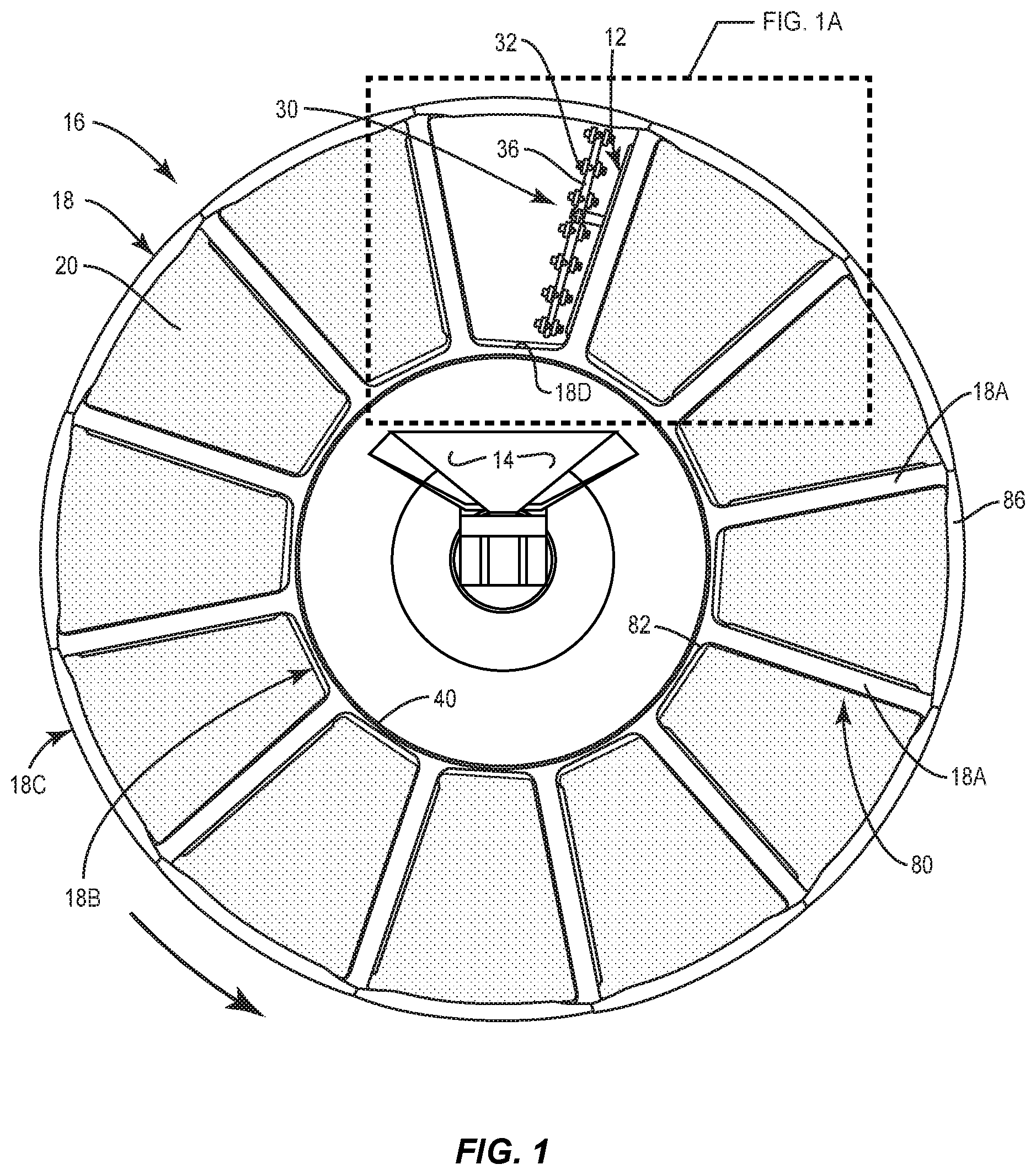
FIG. 1 is a cross-sectional view of a disc filter.
FIG. 1A is an enlarged fragmentary view illustrating a portion of a filter disc that forms a part of the disc filter.
FIG. 1B shows a portion of FIG. 1A and identifies the location of dimension and angle indicators L, H and cp.
FIG. 2 is a schematic cross-sectional view of a portion of the filter disc particularly illustrating the backwash guides.
FIG. 3 is a perspective view of a filter frame module having the backwash guides incorporated therein.
FIG. 4 is a perspective view of the disc filter with portions broken away to better illustrate certain components of the disc filter.
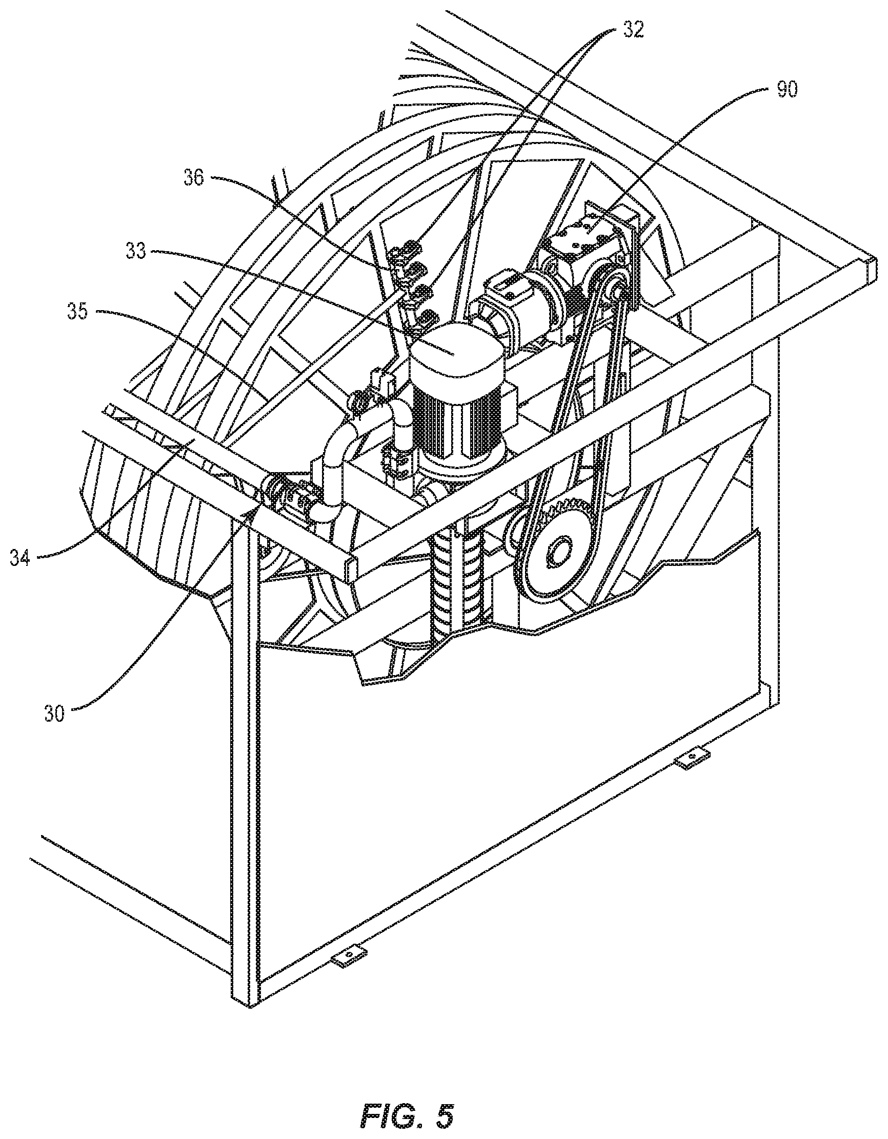
FIG. 5 is a perspective view of a rear portion of the disc filter with portions broken away to better illustrate certain components of the disc filter.
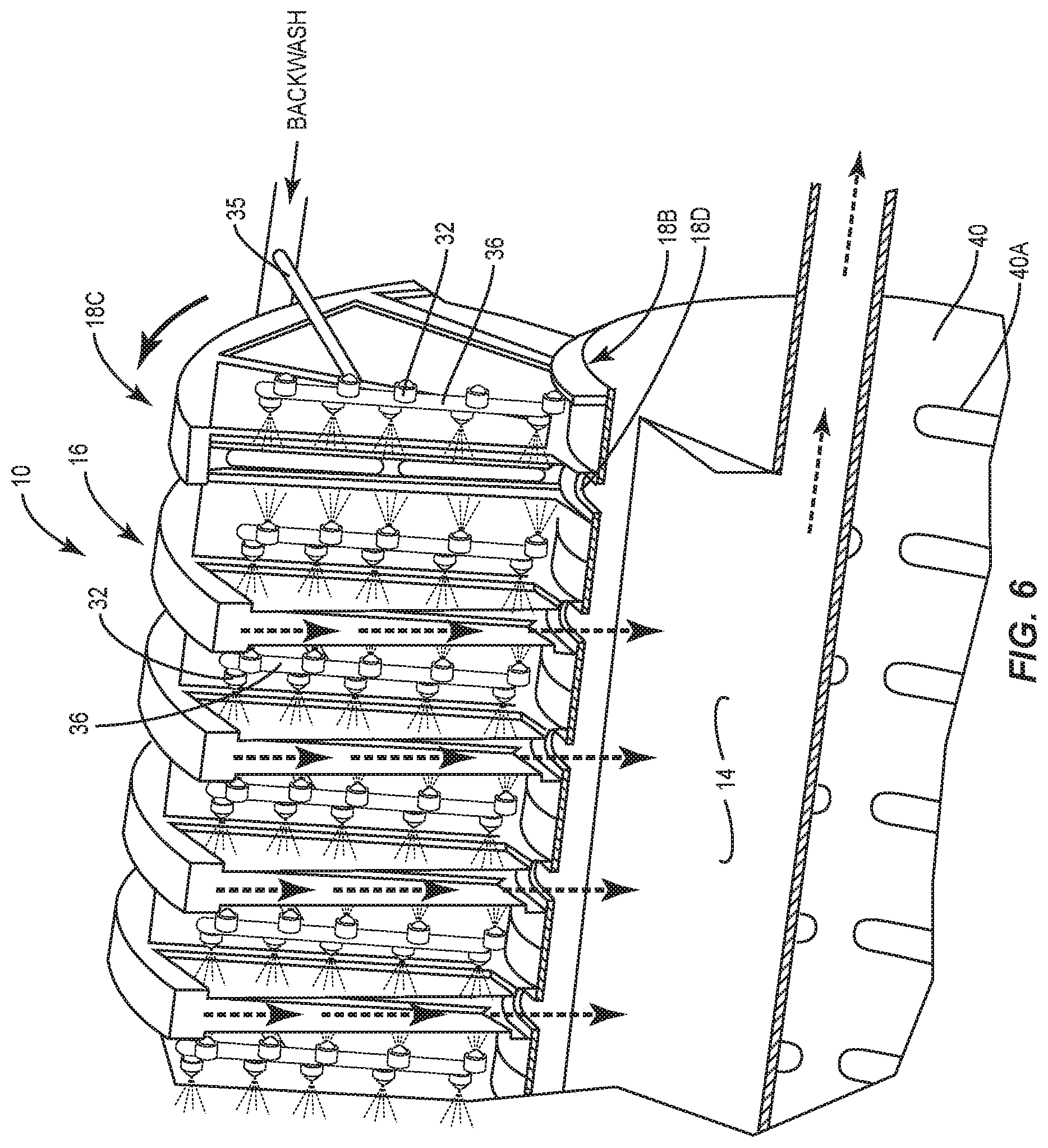
FIG. 6 is a fragmentary perspective view of a portion of the disc filter which illustrates how the backwash guides facilitate the removal of a backwash and suspended solids mixture from the filter disc.
DESCRIPTION OF EXEMPLARY EMBODIMENT
With further reference to the drawings and as discussed above, the present invention relates to a rotary disc filter 10 that is designed to effectively collect suspended solids in a solids trough 14. This is achieved by a series of backwash guides 12 provided in filter discs 16 mounted to a rotary drum 40. See FIGS. 1, 1A and 2. Each filter disc 16 comprises a filter frame 18 and filter segments 20 supported in the filter frame. Filter segments 20 form filter media disposed on opposite sides of the filter disc 16. See FIG. 2. Backwash guides 12 are spaced inwardly from the filter segments 20. This spacing results in the backwash guides 12, filter frame and the filter segments 20 forming backwash channels 22 around the interior of the filter disc 16.
In a backwashing operation, the filter discs 16 and hence the backwash channels 22 are rotated past backwashing nozzles 32 that form a part of the backwashing system 30 and which are disposed on opposite sides of the filter discs 16. Pressurized backwash from the nozzles 32 penetrates the filter segments 20 and enters the filter discs 16, and in the process, suspended solids are dislodged from an inner side of the filter segments 20. Backwash that penetrates the filter segments 20 does not typically continue in the same direction once inside the filter disc 16. The velocity of the backwash on the inner side of the filter segment 20 is relatively low. The backwash which penetrates the filter media tends to run down, by gravity, along the inner sides of the filter media. Expressed in another way, the backwash and suspended solids mixture tends to move by gravity closely adjacent the inner surfaces of the filter segments 20. Backwash channels 22 include open sides that face the direction of rotation of the filter discs 16. As portions of the filter segments 20 move towards and past the backwashing nozzles 32, the backwash channels 22 tend to catch or scoop the mixture of backwash and suspended solids. Since a substantial portion of the backwash and suspended solids mixture moves adjacent the inner surfaces of the filter segments 20, this facilitates the efficient capture of the mixture. Due to the location of the nozzles 32 and the direction of rotation of the filter disc 16, as viewed for example in FIG. 1, the backwash and suspended solids mixture tend to move towards and into oncoming backwash channels 22. Once in the backwash channels 22, the backwash and suspended solids mixture is guided inwardly to and through openings 18D formed in the inner periphery 18B of the filter frame 18. From there, the mixture of backwash and suspended solids passes through openings 40A in the drum 40 and into the solids trough 14 disposed in the drum.
Subsequently, the basic structure and function of the disc filter 10 will be described. But first, the focus is on the filter discs 16 and the backwash guides 12. FIGS. 1 and 1A show a filter disc 16 mounted to the rotary drum 40. Drum 40 includes an array of openings 40A formed in the surface thereof. Each filter disc 16 comprises a filter frame 18 and the filter segments 20 supported in the filter frame. In the embodiment shown in FIG. 1, the filter frame 18 comprises a plurality of circumferentially spaced support arms 18A. Support arms 18A extend between an inner periphery 18B and an outer periphery 18C of the filter frame. Inner periphery 18B of the filter frame 18 also forms the inner periphery of the filter disc 16. Openings 18D are formed in the inner periphery of the filter disc 16. Openings 18D enable water or liquid to flow from the drum 40 into the filter discs 16 during the filtering process. They also allow a mixture of backwash and suspended solids to flow from the filter discs 16 through openings 40D in the drum 40 and into the solids trough 14 disposed in the drum. See FIG. 1.
As noted above, in one embodiment during a backwashing operation, filter discs 16 rotates counterclockwise as viewed in FIG. 1. Backwash guides 12 project from one side of the support arms 18A in the direction of rotation of the filter discs 16. Backwash guides 12 can be integrally formed with the filter frame 18 and particularly with the support arms 18A attached or fastened to a particular filter frame structure or integrally formed with the filter segment 20.
During a backwashing operation, the nozzles 32 are disposed exteriorly of the filter discs 16 and direct a pressurized backwash through the filter segments 20. In the process, suspended solids filtered by the filter segments 20 and retained on the inner side thereof are dislodged. This results in a mixture of backwash and suspended solids in the filter discs 16. The function of the backwash guides 12 and backwash channels 22 is to guide the mixture of backwash and suspended solids out of the filter discs 16 and into the solids trough 14.
To better illustrate the backwash guides 12 and how they facilitate the efficient capture and removal of the backwash and suspended solids mixture, reference is made to FIG. 2. FIG. 2 is a schematic cross-sectional illustration showing a portion of the filter frame 18, filter segments 20 and the backwash guides 12. As noted above, filter frame 18 includes support arms 18A and they are schematically illustrated in FIG. 2. Support arms 18A include an inner portion 18A1, an outer portion 18A2, and a cross portion 18A3. See FIG. 2. Again, this is a schematic illustration and in one embodiment the transversely aligned support arms 18A shown in FIG. 2 can be interconnected. In any event, the support arms 18A form back-to-back grooves that receive and hold seals 54. Filter segments 20 which include a surrounding frame and filter media are in turn received and held in the seals 54.
Continuing to refer to FIG. 2, the backwash guides 12 project from one end of the inner portions 18A1. Again, the backwash guides 12 project in the direction of rotation of the filter discs 16 during backwashing as shown in FIGS. 1 and 2. Note that the backwash guides 12 also project inwardly into the filter disc 16. Further, the backwash guides 12 are circumferentially spaced around the filter disc 16. Backwash guides 12 are arranged in pairs. That is, two backwash guides 12 are transversely aligned and disposed across from each other. See FIG. 2. The backwash guides 12 project slightly towards each other. This forms an open space 60 between each pair of backwash guides 12. This open space enables water or liquid to pass through the open space when the filter discs 16 are rotated.
Backwash guides 12 in one embodiment effectively form an elongated edge that extends between the inner and outer peripheries 18B and 18C of the filter frame 18. Further, the backwash guides 12, along with portions of the support arms 18A, seals 54 and filter segments 20 form the backwash channels 22. See FIG. 2. During a backwashing operation, the backwash channels 22 effectively entrap a mixture of backwash and suspended solids and guide or direct the mixture to openings 18D formed in the inner periphery 18B of the filter frame 18. As noted before, this enables the backwash and suspended solids mixture to pass through the array of openings 40A in the drum 40 and into the underlying solids trough 14.
As noted above, during a backwashing operation, the drum 40 and the filter discs 16 can be rotated. Filter segments 20 are rotated to an upper position on the disc filter 10 where the nozzles 32 are stationed. As the backwash guides 12 approach the nozzles 32 and move past the nozzles, backwash from the nozzles 32 penetrate the filter segments 20 and enter the interior of the filter discs 16. When this happens, the backwash and dislodged suspended solids form a mixture. The backwash guides 12 tend to urge the backwash and suspended solids mixture into the backwash channels 22. The backwash guides 12 and the backwash channels 22 tend to catch or scoop the backwash and suspended solids mixture that ends up inside the filter disc 16. Once in the backwash channels 22, the backwash and suspended solids mixture is directed along the channels 22. Inner portions of the backwash channels 22 terminate adjacent the openings 18D in the inner periphery 18B of the filter frame or filter disc. Thus, the backwash channels 22 effectively guide or direct the backwash and suspended solids mixture into the openings 18D of the filter frame 18. From there, as discussed above, the backwash and suspended solid mixture passes through openings 40A in the drum 40 and into the solids trough 14.
In some embodiments, the filter frame 18 is modular and is constructed of interchangeable modules. The modules can be constructed of plastic or other suitable materials. With reference to FIG. 3, there is shown therein one of the modules 80 employed in the filter frame 18 shown in FIG. 1. In this example, the module 80 is constructed of plastic and includes a base 82. Bases 82 of the modules form the inner periphery 18B of the filter frame 18. Note that the bases 82 are interconnected in back-to-back relationship and secured around and to the drum 40. Each base 82 includes openings on opposite sides. These openings form openings 18D in the inner periphery 18B of the filter frame. Extending upwardly from the bases 82 are the support arms 18A that has been discussed above. As seen in FIG. 1, outer covers 86 are interconnected between adjacent modules 80. Thus, the modules 80, along with the outer covers 86, form the filter frame 18 shown in FIG. 1.
Formed on opposite sides of each module 80 is a pair of filter grooves. These filter grooves receive the surrounding frames of respective filter segments 20. A seal can be interposed between the filter segments 20 and the filter grooves.
FIG. 3 depicts one way in which the backwash guides 12 can be incorporated into the modules 80. Note that a pair of backwash guides 12 extends along a leading side of the support arms 18A of the modules 80. In particular, each backwashing guide 12 is integrally formed with a portion of the support arms 18A and projects slightly inwardly therefrom in the manner illustrated in FIG. 2. Therefore, on the leading side of each support arm 18A there is provided a pair of backwash guides 12 that extend over a substantial length of the support arms 18A. Note that these backwash guides 12, in conjunction with the modules 80 and the filter segments 20, also form a pair of backwash channels 22 on leading sides of the support arms. Backwash channels 22 include inner terminal ends that terminate adjacent the openings in the bases 82. Thus as described above, during a backwashing operation backwash channels 22 function to guide and direct a mixture of backwash and suspended solids to the openings formed in the bases 82 of the modules 80. And like discussed above, the openings in the bases 82 are aligned with openings 40A of the drum 40 and hence the backwash and suspended solids mixture passing from the openings in the bases 82 flows through the openings 40A into the underlying solids trough 14.
The volume and dimensions of the backwash channels 22 can vary. This is especially the case because the width of the filter disc 16 varies from one disc filter to another. FIG. 1B uses L, H and .phi. to denote dimensions and an angle relative to the backwash guides 12. Again, the length of L and H, as well as the angle .phi., will vary. However, in exemplary embodiments, L would typically be 5-85 mm, H 3-40 mm, and .phi. 2.degree.-83.degree..
FIG. 6 illustrates how the backwash guides 12 and the backwash channels 22 facilitate the recovery of the backwash and suspended solids mixture and how they guide and direct the mixture into the solids trough 14. The flow of the backwash and suspended solids mixture is shown by heavy dotted lines and arrows in FIG. 6. FIG. 6 does not show the backwash channels 22. The dotted lines and arrows are meant to simply represent the flow of the backwash and suspended solids mixture through the respective filter discs 16. Note also in FIG. 6 where the flow of the mixture passes through openings 18D in the inner periphery of the filter frame and from there through the array of openings 40A formed in the drum and then into the underlying solids trough 14.
The filter discs 16, drum 40, along with the backwash guides 12 and the backwash channels 22 are incorporated into a disc filter 10. It may be beneficial to briefly review the basic design of an exemplary disc filter. The disc filter 10, shown in FIGS. 4 and 5, includes a housing. Some rotary disc filters (a second type) are not provided with a substantial housing structure. These disc filters are often referred to as frame-type disc filters as they are designed to be installed in a pre-formed concrete basin. There is yet a third type or version of a disc filter which includes a half tank or frame with a bottom and sides and which only reaches to about the center of the drum of the disc filter.
In any event, either type of disc filter is provided with a frame structure for supporting various components that make up the disc filter. In this regard, the drum 40 is rotatively mounted on the frame structure of the disc filter. Generally the drum 40 is closed except that it includes an inlet opening and the array of openings 40A discussed above. The filter discs 16 are secured to the drum 40 and rotatable therewith during a backwashing operation. During the filtering of water or liquid, influent water or liquid is directed into the inlet of the drum 40 and from the drum into the filter discs 16 secured on the drum. The number of filter discs 16 secured to the drum can vary. A water holding area is defined inside each filter discs 16 for receiving and holding water or liquid to be filtered by the disc filter 10. Head pressure associated with the influent liquid or water is effective to cause the water or liquid to flow outwardly from the filter discs 16 and through the filter segments 20. Water exiting the filter discs 16 is filtered water or filtrate. As discussed above, this results in suspended solids in the water or liquid being captured or retained on the inner surfaces of the filter segments 20.
Filtered water or liquid exiting the filter discs 16 is collected in a holding chamber that underlies the filter discs. This holding chamber or area includes an outlet that enables the filtered water or liquid to be discharged from the disc filter 10.
During the backwashing operation, it is necessary for the drum 40 and the filter discs 16 mounted thereon to rotate. Disc filter 10 is provided with a drive system for rotatively driving the drum 40 and the filter discs 16. In the case of the embodiment illustrated in FIGS. 4 and 5, mounted to a panel or wall structure about the back portion of the disc filter 10 is a drum motor 90 that is operative to drive a sprocket or sheave connected to a shaft on which the drum 40 is mounted. See FIG. 5. Various means can be operatively interconnected between the drum motor 90 and the sprocket or sheave for rotating the drum 40. In one example, a chain drive is utilized to drive a sprocket secured to the shaft that rotates the drum 40. Various other types of drive systems can be utilized to rotate the drum and the filter discs 16. In some cases, for example, there may be a direct drive on the drum shaft from a gear motor.
Returning to the backwash system 30 discussed above, the system comprises a backwash pump 33, a manifold 34 that extends along a side portion of the disc filter 10, and a series of feed tubes 35 connected to the manifold 34 and projecting inwardly therefrom. Feed tubes 35, sometimes referred to as inner pipes, project from the manifold 34 into areas between respective filter discs 16. Secured to the feed tubes 35 are a series of nozzle holders or nozzle bars 36. Nozzles 32 are mounted on the nozzle bars 38. In a preferred embodiment, the backwash pump 33 forms a part of the disc filter. In other embodiments, pressurized backwash can be provided from a source other than a backwash pump that forms a part of the disc filter 10.
Manifold 34 can be rigidly mounted or rotatively mounted along one side of the disc filter 10. In some cases, manifold 34 is operatively connected to a drive (not shown) that can be indirectly driven from the drum motor 90. In any event, the manifold 34, during a cleaning operation, can oscillate back and forth, which results in the nozzles 32 sweeping back and forth between the filter discs 16 so as to backwash particular areas of the filter segments 20 disposed on opposite sides of the filter discs 16. In other cases, the manifold 24 is rigidly mounted and does not oscillate back and forth during the backwashing operation.
There are many advantages to the backwash guides 12. They assure that a larger percentage of the backwash and suspended solids mixture end up in the solids trough 14. One measure of the effectiveness of the backwash guides 12 can be appreciated from examining what is referred to herein as "separation speed of suspended solids" (mg separated suspended solids/s). In order to determine the separation speed of suspended solids, the first step is to measure the flow of the backwash and suspended solids mixture being discharged by the disc filter 10. Secondly, a sample of the flow of the backwash and suspended solids mixture is taken and a total suspended solids (TSS) test is carried out which gives the concentration of suspended solids (mg/L) of the backwash and suspended solids mixture. The separation speed of the suspended solids is defined as the product of the flow and the suspended solids concentration. The employment of the backwash guides 12 will, in most cases, increase the separation speed of the suspended solids.
"Configured to" is used in this application. The term "configured to" means "designed to".
The present invention may, of course, be carried out in other specific ways than those herein set forth without departing from the scope and the essential characteristics of the invention. The present embodiments are therefore to be construed in all aspects as illustrative and not restrictive and all changes coming within the meaning and equivalency range of the appended claims are intended to be embraced therein.
* * * * *
D00000
D00001
D00002
D00003
D00004
D00005
D00006
D00007
D00008
XML
uspto.report is an independent third-party trademark research tool that is not affiliated, endorsed, or sponsored by the United States Patent and Trademark Office (USPTO) or any other governmental organization. The information provided by uspto.report is based on publicly available data at the time of writing and is intended for informational purposes only.
While we strive to provide accurate and up-to-date information, we do not guarantee the accuracy, completeness, reliability, or suitability of the information displayed on this site. The use of this site is at your own risk. Any reliance you place on such information is therefore strictly at your own risk.
All official trademark data, including owner information, should be verified by visiting the official USPTO website at www.uspto.gov. This site is not intended to replace professional legal advice and should not be used as a substitute for consulting with a legal professional who is knowledgeable about trademark law.