Seals for surgical access devices
Vaccarella , et al. May 11, 2
U.S. patent number 11,000,313 [Application Number 16/394,043] was granted by the patent office on 2021-05-11 for seals for surgical access devices. This patent grant is currently assigned to Covidien LP. The grantee listed for this patent is Covidien LP. Invention is credited to Garrett Ebersole, Robert Pedros, Lorenzo Vaccarella.


| United States Patent | 11,000,313 |
| Vaccarella , et al. | May 11, 2021 |
Seals for surgical access devices
Abstract
A cannula for use in an access assembly includes an instrument valve housing including first and second housing sections and defining a cavity and a valve assembly disposed within the cavity of the instrument valve housing. The valve assembly includes a seal assembly including an outer flange and a septum seal extending across the outer flange, a guard assembly disposed within the outer flange of the seal assembly, and a centering mechanism. The guard assembly includes a plurality of guard members. Each guard member of the plurality of guard members includes a ring portion and a flap portion. The flap portions of the guard members of the guard assembly are configured to engage and stretch the septum seal during reception of a surgical instrument through the valve assembly.
| Inventors: | Vaccarella; Lorenzo (Bellingham, MA), Ebersole; Garrett (Hamden, CT), Pedros; Robert (Oxford, CT) | ||||||||||
|---|---|---|---|---|---|---|---|---|---|---|---|
| Applicant: |
|
||||||||||
| Assignee: | Covidien LP (Mansfield,
MA) |
||||||||||
| Family ID: | 70470820 | ||||||||||
| Appl. No.: | 16/394,043 | ||||||||||
| Filed: | April 25, 2019 |
Prior Publication Data
| Document Identifier | Publication Date | |
|---|---|---|
| US 20200337723 A1 | Oct 29, 2020 | |
| Current U.S. Class: | 1/1 |
| Current CPC Class: | A61M 39/0613 (20130101); A61B 17/3498 (20130101); A61B 17/3423 (20130101); A61B 17/3462 (20130101); A61B 17/3421 (20130101); A61B 17/3439 (20130101); A61B 2017/3419 (20130101); A61M 2039/0626 (20130101); A61B 2017/3464 (20130101); A61M 13/00 (20130101); A61M 2039/062 (20130101); A61M 2039/066 (20130101); A61M 2039/0673 (20130101) |
| Current International Class: | A61B 17/34 (20060101); A61M 13/00 (20060101) |
References Cited [Referenced By]
U.S. Patent Documents
| 3402710 | September 1968 | Paleschuck |
| 3495586 | February 1970 | Regenbogen |
| 4016884 | April 1977 | Kwan-Gett |
| 4112932 | September 1978 | Chiulli |
| 4183357 | January 1980 | Bentley et al. |
| 4356826 | November 1982 | Kubota |
| 4402683 | September 1983 | Kopman |
| 4653476 | March 1987 | Bonnet |
| 4737148 | April 1988 | Blake |
| 4863430 | September 1989 | Klyce et al. |
| 4863438 | September 1989 | Gauderer et al. |
| 4984564 | January 1991 | Yuen |
| 5002557 | March 1991 | Hasson |
| 5073169 | December 1991 | Raiken |
| 5082005 | January 1992 | Kaldany |
| 5122122 | June 1992 | Allgood |
| 5159921 | November 1992 | Hoover |
| 5176697 | January 1993 | Hasson et al. |
| 5183471 | February 1993 | Wilk |
| 5192301 | March 1993 | Kamiya et al. |
| 5209741 | May 1993 | Spaeth |
| 5209754 | May 1993 | Ahluwalia |
| 5217466 | June 1993 | Hasson |
| 5242409 | September 1993 | Buelna |
| 5242415 | September 1993 | Kantrowitz et al. |
| 5257973 | November 1993 | Villasuso |
| 5257975 | November 1993 | Foshee |
| 5269772 | December 1993 | Wilk |
| 5290249 | March 1994 | Foster et al. |
| 5312391 | May 1994 | Wilk |
| 5312417 | May 1994 | Wilk |
| 5314417 | May 1994 | Stephens et al. |
| 5318516 | June 1994 | Cosmescu |
| 5330486 | July 1994 | Wilk |
| 5334143 | August 1994 | Carroll |
| 5336169 | August 1994 | Divilio et al. |
| 5336203 | August 1994 | Goldhardt et al. |
| 5337937 | August 1994 | Remiszewski et al. |
| 5345927 | September 1994 | Bonutti |
| 5360417 | November 1994 | Gravener et al. |
| 5366478 | November 1994 | Brinkerhoff et al. |
| 5375588 | December 1994 | Yoon |
| 5378588 | January 1995 | Tsuchiya |
| 5391156 | February 1995 | Hildwein et al. |
| 5394863 | March 1995 | Sanford et al. |
| 5395367 | March 1995 | Wilk |
| 5437683 | August 1995 | Neumann et al. |
| 5445615 | August 1995 | Yoon |
| 5451222 | September 1995 | De Maagd et al. |
| 5460170 | October 1995 | Hammerslag |
| 5464409 | November 1995 | Mohajer |
| 5480410 | January 1996 | Cuschieri et al. |
| 5490843 | February 1996 | Hildwein et al. |
| 5507758 | April 1996 | Thomason et al. |
| 5511564 | April 1996 | Wilk |
| 5514133 | May 1996 | Golub et al. |
| 5514153 | May 1996 | Bonutti |
| 5520698 | May 1996 | Koh |
| 5522791 | June 1996 | Leyva |
| 5524644 | June 1996 | Crook |
| 5540648 | July 1996 | Yoon |
| 5545150 | August 1996 | Danks et al. |
| 5545179 | August 1996 | Williamson, IV |
| 5556385 | September 1996 | Andersen |
| 5569159 | October 1996 | Anderson et al. |
| 5577993 | November 1996 | Zhu et al. |
| 5601581 | February 1997 | Fogarty et al. |
| 5624399 | April 1997 | Ackerman |
| 5634911 | June 1997 | Hermann et al. |
| 5634937 | June 1997 | Mollenauer et al. |
| 5643285 | July 1997 | Rowden et al. |
| 5649550 | July 1997 | Crook |
| 5651771 | July 1997 | Tangherlini et al. |
| 5653705 | August 1997 | de la Torre et al. |
| 5656013 | August 1997 | Yoon |
| 5672168 | September 1997 | de la Torre et al. |
| 5683378 | November 1997 | Christy |
| 5685857 | November 1997 | Negus et al. |
| 5697946 | December 1997 | Hopper et al. |
| 5709675 | January 1998 | Williams |
| 5713858 | February 1998 | Heruth et al. |
| 5713869 | February 1998 | Morejon |
| 5722962 | March 1998 | Garcia |
| 5728103 | March 1998 | Picha et al. |
| 5730748 | March 1998 | Fogarty et al. |
| 5735791 | April 1998 | Alexander, Jr. et al. |
| 5741298 | April 1998 | MacLeod |
| 5752970 | May 1998 | Yoon |
| 5782817 | July 1998 | Franzel et al. |
| 5795290 | August 1998 | Bridges |
| 5803921 | September 1998 | Bonadio |
| 5810712 | September 1998 | Dunn |
| 5813409 | September 1998 | Leahy et al. |
| 5830191 | November 1998 | Hildwein et al. |
| 5836871 | November 1998 | Wallace et al. |
| 5836913 | November 1998 | Orth et al. |
| 5840077 | November 1998 | Rowden et al. |
| 5842971 | December 1998 | Yoon |
| 5848992 | December 1998 | Hart et al. |
| 5853417 | December 1998 | Fogarty et al. |
| 5857461 | January 1999 | Levitsky et al. |
| 5865817 | February 1999 | Moenning et al. |
| 5871474 | February 1999 | Hermann et al. |
| 5876413 | March 1999 | Fogarty et al. |
| 5894843 | April 1999 | Benetti et al. |
| 5899208 | May 1999 | Bonadio |
| 5899913 | May 1999 | Fogarty et al. |
| 5904703 | May 1999 | Gilson |
| 5906577 | May 1999 | Beane et al. |
| 5914415 | June 1999 | Tago |
| 5916198 | June 1999 | Dillow |
| 5941898 | August 1999 | Moenning et al. |
| 5951588 | September 1999 | Moenning |
| 5957913 | September 1999 | de la Torre et al. |
| 5964781 | October 1999 | Mollenauer et al. |
| 5976174 | November 1999 | Ruiz |
| 5997515 | December 1999 | de la Torre et al. |
| 6017355 | January 2000 | Hessel et al. |
| 6018094 | January 2000 | Fox |
| 6024736 | February 2000 | de la Torre et al. |
| 6030402 | February 2000 | Thompson et al. |
| 6033426 | March 2000 | Kaji |
| 6033428 | March 2000 | Sardella |
| 6042573 | March 2000 | Lucey |
| 6048309 | April 2000 | Flom et al. |
| 6059816 | May 2000 | Moenning |
| 6068639 | May 2000 | Fogarty et al. |
| 6077288 | June 2000 | Shimomura et al. |
| 6086603 | July 2000 | Termin et al. |
| 6099506 | August 2000 | Macoviak et al. |
| 6110154 | August 2000 | Shimomura et al. |
| 6142936 | November 2000 | Beane et al. |
| 6156006 | December 2000 | Brosens et al. |
| 6162196 | December 2000 | Hart et al. |
| 6171282 | January 2001 | Ragsdale |
| 6197002 | March 2001 | Peterson |
| 6217555 | April 2001 | Hart et al. |
| 6228063 | May 2001 | Aboul-Hosn |
| 6234958 | May 2001 | Snoke et al. |
| 6238373 | May 2001 | de la Torre et al. |
| 6241768 | June 2001 | Agarwal et al. |
| 6251119 | June 2001 | Addis |
| 6254534 | July 2001 | Butler et al. |
| 6264604 | July 2001 | Kieturakis et al. |
| 6276661 | August 2001 | Laird |
| 6293952 | September 2001 | Brosens et al. |
| 6315770 | November 2001 | de la Torre et al. |
| 6319246 | November 2001 | de la Torre et al. |
| 6328720 | December 2001 | McNally et al. |
| 6329637 | December 2001 | Hembree et al. |
| 6371968 | April 2002 | Kogasaka et al. |
| 6382211 | May 2002 | Crook |
| 6423036 | July 2002 | Van Huizen |
| 6440061 | August 2002 | Wenner et al. |
| 6440063 | August 2002 | Beane et al. |
| 6443957 | September 2002 | Addis |
| 6447489 | September 2002 | Peterson |
| 6450983 | September 2002 | Rambo |
| 6454783 | September 2002 | Piskun |
| 6464686 | October 2002 | O'Hara et al. |
| 6468292 | October 2002 | Mollenauer et al. |
| 6485410 | November 2002 | Loy |
| 6488620 | December 2002 | Segermark et al. |
| 6488692 | December 2002 | Spence et al. |
| 6524283 | February 2003 | Hopper et al. |
| 6527787 | March 2003 | Fogarty et al. |
| 6544210 | April 2003 | Trudel et al. |
| 6551270 | April 2003 | Bimbo et al. |
| 6558371 | May 2003 | Dorn |
| 6562022 | May 2003 | Hoste et al. |
| 6572631 | June 2003 | McCartney |
| 6578577 | June 2003 | Bonadio et al. |
| 6582364 | June 2003 | Butler et al. |
| 6589167 | July 2003 | Shimomura et al. |
| 6589316 | July 2003 | Schultz et al. |
| 6592543 | July 2003 | Wortrich et al. |
| 6613952 | September 2003 | Rambo |
| 6623426 | September 2003 | Bonadio et al. |
| 6669674 | December 2003 | Macoviak et al. |
| 6676639 | January 2004 | Ternstrom |
| 6684405 | February 2004 | Lezdey |
| 6706050 | March 2004 | Giannadakis |
| 6716201 | April 2004 | Blanco |
| 6723044 | April 2004 | Pulford et al. |
| 6723088 | April 2004 | Gaskill, III et al. |
| 6725080 | April 2004 | Melkent et al. |
| 6800084 | October 2004 | Davison et al. |
| 6811546 | November 2004 | Callas et al. |
| 6814078 | November 2004 | Crook |
| 6830578 | December 2004 | O'Heeron et al. |
| 6837893 | January 2005 | Miller |
| 6840946 | January 2005 | Fogarty et al. |
| 6840951 | January 2005 | de la Torre et al. |
| 6846287 | January 2005 | Bonadio et al. |
| 6863674 | March 2005 | Kasahara et al. |
| 6878110 | April 2005 | Yang et al. |
| 6884253 | April 2005 | McFarlane |
| 6890295 | May 2005 | Michels et al. |
| 6913609 | July 2005 | Yencho et al. |
| 6916310 | July 2005 | Sommerich |
| 6916331 | July 2005 | Mollenauer et al. |
| 6929637 | August 2005 | Gonzalez et al. |
| 6939296 | September 2005 | Ewers et al. |
| 6942633 | September 2005 | Odland |
| 6945932 | September 2005 | Caldwell et al. |
| 6958037 | October 2005 | Ewers et al. |
| 6972026 | December 2005 | Caldwell et al. |
| 6986752 | January 2006 | McGuckin, Jr. et al. |
| 6991602 | January 2006 | Nakazawa et al. |
| 6997909 | February 2006 | Goldberg |
| 7001397 | February 2006 | Davison et al. |
| 7008377 | March 2006 | Beane et al. |
| 7011645 | March 2006 | McGuckin, Jr. et al. |
| 7014628 | March 2006 | Bousquet |
| 7033319 | April 2006 | Pulford et al. |
| 7052454 | May 2006 | Taylor |
| 7056321 | June 2006 | Pagliuca et al. |
| 7077852 | July 2006 | Fogarty et al. |
| 7081089 | July 2006 | Bonadio et al. |
| 7083626 | August 2006 | Hart et al. |
| 7100614 | September 2006 | Stevens et al. |
| 7101353 | September 2006 | Lui et al. |
| 7104981 | September 2006 | Elkins et al. |
| 7153261 | December 2006 | Wenchell |
| 7160309 | January 2007 | Voss |
| 7163510 | January 2007 | Kahle et al. |
| 7192436 | March 2007 | Sing et al. |
| 7195590 | March 2007 | Butler et al. |
| 7201725 | April 2007 | Cragg et al. |
| 7214185 | May 2007 | Rosney et al. |
| 7217277 | May 2007 | Parihar et al. |
| 7223257 | May 2007 | Shubayev et al. |
| 7223278 | May 2007 | Davison et al. |
| 7235064 | June 2007 | Hopper et al. |
| 7235084 | June 2007 | Skakoon et al. |
| 7238154 | July 2007 | Ewers et al. |
| 7258712 | August 2007 | Schultz et al. |
| 7276075 | October 2007 | Callas et al. |
| 7294103 | November 2007 | Bertolero et al. |
| 7300399 | November 2007 | Bonadio et al. |
| 7316699 | January 2008 | McFarlane |
| 7331940 | February 2008 | Sommerich |
| 7344547 | March 2008 | Piskun |
| 7377898 | May 2008 | Ewers et al. |
| 7390322 | June 2008 | McGuckin, Jr. et al. |
| 7393322 | July 2008 | Wenchell |
| 7412977 | August 2008 | Fields et al. |
| 7440661 | October 2008 | Kobayashi |
| 7445597 | November 2008 | Butler et al. |
| 7452363 | November 2008 | Ortiz |
| 7473221 | January 2009 | Ewers et al. |
| 7481765 | January 2009 | Ewers et al. |
| 7493703 | February 2009 | Kim et al. |
| 7513361 | April 2009 | Mills, Jr. |
| 7513461 | April 2009 | Reutenauer et al. |
| 7520876 | April 2009 | Ressemann et al. |
| 7537564 | May 2009 | Bonadio et al. |
| 7540839 | June 2009 | Butler et al. |
| 7559893 | July 2009 | Bonadio et al. |
| 7608082 | October 2009 | Cuevas et al. |
| 7625361 | December 2009 | Suzuki et al. |
| 7645232 | January 2010 | Shluzas |
| 7650887 | January 2010 | Nguyen et al. |
| 7704207 | April 2010 | Albrecht et al. |
| 7717846 | May 2010 | Zirps et al. |
| 7717847 | May 2010 | Smith |
| 7721742 | May 2010 | Kalloo et al. |
| 7727146 | June 2010 | Albrecht et al. |
| 7730629 | June 2010 | Kim |
| 7736306 | June 2010 | Brustad et al. |
| 7753901 | July 2010 | Piskun et al. |
| 7758500 | July 2010 | Boyd et al. |
| 7762995 | July 2010 | Eversull et al. |
| 7766824 | August 2010 | Jensen et al. |
| 7787963 | August 2010 | Geistert et al. |
| 7798998 | September 2010 | Thompson et al. |
| 7811251 | October 2010 | Wenchell et al. |
| 7815567 | October 2010 | Albrecht et al. |
| 7837612 | November 2010 | Gill et al. |
| 7846123 | December 2010 | Vassiliades et al. |
| 7850600 | December 2010 | Piskun |
| 7850667 | December 2010 | Gresham |
| 7867164 | January 2011 | Butler et al. |
| 7896889 | March 2011 | Mazzocchi et al. |
| 7905829 | March 2011 | Nishimura et al. |
| 7909760 | March 2011 | Albrecht et al. |
| 7913697 | March 2011 | Nguyen et al. |
| 7951076 | May 2011 | Hart et al. |
| 7955257 | June 2011 | Frasier et al. |
| 7955313 | June 2011 | Boismier |
| 7998068 | August 2011 | Bonadio et al. |
| 8021296 | September 2011 | Bonadio et al. |
| 8025670 | September 2011 | Sharp et al. |
| 8038652 | October 2011 | Morrison et al. |
| 8066673 | November 2011 | Hart et al. |
| 8079986 | December 2011 | Taylor et al. |
| 8092430 | January 2012 | Richard et al. |
| 8105234 | January 2012 | Ewers et al. |
| 8109873 | February 2012 | Albrecht et al. |
| 8157786 | April 2012 | Miller et al. |
| 8157817 | April 2012 | Bonadio et al. |
| 8187177 | May 2012 | Kahle et al. |
| 8187178 | May 2012 | Bonadio et al. |
| 8241209 | August 2012 | Shelton, IV et al. |
| 8262568 | September 2012 | Albrecht et al. |
| 8323184 | December 2012 | Spiegal et al. |
| 8335783 | December 2012 | Milby |
| 8343047 | January 2013 | Albrecht et al. |
| 8353824 | January 2013 | Shelton, IV et al. |
| 8403889 | March 2013 | Richard |
| 8480683 | July 2013 | Fowler et al. |
| 8574153 | November 2013 | Richard |
| 8585632 | November 2013 | Okoniewski |
| 2001/0037053 | November 2001 | Bonadio et al. |
| 2002/0055714 | May 2002 | Rothschild |
| 2003/0014076 | January 2003 | Mollenauer et al. |
| 2003/0093104 | May 2003 | Bonner et al. |
| 2003/0187376 | October 2003 | Rambo |
| 2003/0233115 | December 2003 | Eversull et al. |
| 2003/0236549 | December 2003 | Bonadio et al. |
| 2004/0059297 | March 2004 | Racenet et al. |
| 2004/0092795 | May 2004 | Bonadio et al. |
| 2004/0102804 | May 2004 | Chin |
| 2004/0111061 | June 2004 | Curran |
| 2004/0138529 | July 2004 | Wiltshire et al. |
| 2004/0204734 | October 2004 | Wagner et al. |
| 2004/0267096 | December 2004 | Caldwell et al. |
| 2005/0020884 | January 2005 | Hart et al. |
| 2005/0070935 | March 2005 | Ortiz |
| 2005/0096695 | May 2005 | Olich |
| 2005/0119525 | June 2005 | Takemoto |
| 2005/0137459 | June 2005 | Chin et al. |
| 2005/0148823 | July 2005 | Vaugh et al. |
| 2005/0192483 | September 2005 | Bonadio et al. |
| 2005/0203346 | September 2005 | Bonadio et al. |
| 2005/0209608 | September 2005 | O'Heeron |
| 2005/0245876 | November 2005 | Khosravi et al. |
| 2005/0251092 | November 2005 | Howell et al. |
| 2005/0277946 | December 2005 | Greenhalgh |
| 2006/0071432 | April 2006 | Staudner |
| 2006/0129165 | June 2006 | Edoga et al. |
| 2006/0149137 | July 2006 | Pingleton et al. |
| 2006/0149306 | July 2006 | Hart et al. |
| 2006/0161049 | July 2006 | Beane et al. |
| 2006/0161050 | July 2006 | Butler et al. |
| 2006/0212063 | September 2006 | Wilk |
| 2006/0224161 | October 2006 | Bhattacharyya |
| 2006/0241651 | October 2006 | Wilk |
| 2006/0247498 | November 2006 | Bonadio et al. |
| 2006/0247499 | November 2006 | Butler et al. |
| 2006/0247500 | November 2006 | Voegele et al. |
| 2006/0247516 | November 2006 | Hess et al. |
| 2006/0247586 | November 2006 | Voegele et al. |
| 2006/0247673 | November 2006 | Voegele et al. |
| 2006/0247678 | November 2006 | Weisenburgh et al. |
| 2006/0270911 | November 2006 | Voegele et al. |
| 2007/0093695 | April 2007 | Bonadio et al. |
| 2007/0118175 | May 2007 | Butler et al. |
| 2007/0151566 | July 2007 | Kahle et al. |
| 2007/0203398 | August 2007 | Bonadio et al. |
| 2007/0208312 | September 2007 | Norton et al. |
| 2007/0225650 | September 2007 | Hart et al. |
| 2007/0270654 | November 2007 | Pignato et al. |
| 2007/0270882 | November 2007 | Hjelle et al. |
| 2008/0009826 | January 2008 | Miller et al. |
| 2008/0021360 | January 2008 | Fihe et al. |
| 2008/0027476 | January 2008 | Piskun |
| 2008/0048011 | February 2008 | Weller |
| 2008/0091143 | April 2008 | Taylor et al. |
| 2008/0097162 | April 2008 | Bonadio et al. |
| 2008/0097332 | April 2008 | Greenhalgh et al. |
| 2008/0119868 | May 2008 | Sharp et al. |
| 2008/0161826 | July 2008 | Guiraudon |
| 2008/0188868 | August 2008 | Weitzner et al. |
| 2008/0194973 | August 2008 | Imam |
| 2008/0200767 | August 2008 | Ewers et al. |
| 2008/0255519 | October 2008 | Piskun et al. |
| 2008/0319261 | December 2008 | Lucini et al. |
| 2009/0012477 | January 2009 | Norton et al. |
| 2009/0036738 | February 2009 | Cuschieri et al. |
| 2009/0036745 | February 2009 | Bonadio et al. |
| 2009/0093752 | April 2009 | Richard et al. |
| 2009/0093850 | April 2009 | Richard |
| 2009/0105635 | April 2009 | Bettuchi et al. |
| 2009/0131751 | May 2009 | Spivey et al. |
| 2009/0137879 | May 2009 | Ewers et al. |
| 2009/0182279 | July 2009 | Wenchell et al. |
| 2009/0182288 | July 2009 | Spenciner |
| 2009/0187079 | July 2009 | Albrecht et al. |
| 2009/0204067 | August 2009 | Abu-Halawa |
| 2009/0221968 | September 2009 | Morrison et al. |
| 2009/0227843 | September 2009 | Smith et al. |
| 2009/0326330 | December 2009 | Bonadio et al. |
| 2009/0326332 | December 2009 | Carter |
| 2010/0063452 | March 2010 | Edelman et al. |
| 2010/0100043 | April 2010 | Racenet |
| 2010/0113886 | May 2010 | Piskun et al. |
| 2010/0228094 | September 2010 | Ortiz et al. |
| 2010/0240960 | September 2010 | Richard |
| 2010/0249516 | September 2010 | Shelton, IV et al. |
| 2010/0249523 | September 2010 | Spiegal et al. |
| 2010/0249524 | September 2010 | Ransden et al. |
| 2010/0262080 | October 2010 | Shelton, IV et al. |
| 2010/0280326 | November 2010 | Hess et al. |
| 2010/0286484 | November 2010 | Stellon et al. |
| 2010/0286506 | November 2010 | Ransden et al. |
| 2010/0298646 | November 2010 | Stellon et al. |
| 2010/0312063 | December 2010 | Hess et al. |
| 2011/0009704 | January 2011 | Marczyk et al. |
| 2011/0021877 | January 2011 | Fortier et al. |
| 2011/0028891 | February 2011 | Okoniewski |
| 2011/0034778 | February 2011 | Kleyman |
| 2011/0054257 | March 2011 | Stopek |
| 2011/0054258 | March 2011 | O'Keefe et al. |
| 2011/0054260 | March 2011 | Albrecht et al. |
| 2011/0082341 | April 2011 | Kleyman et al. |
| 2011/0082343 | April 2011 | Okoniewski |
| 2011/0082346 | April 2011 | Stopek |
| 2011/0118553 | May 2011 | Stopek |
| 2011/0124968 | May 2011 | Kleyman |
| 2011/0124969 | May 2011 | Stopek |
| 2011/0124970 | May 2011 | Kleyman |
| 2011/0125186 | May 2011 | Fowler et al. |
| 2011/0166423 | July 2011 | Farascioni et al. |
| 2011/0251463 | October 2011 | Kleyman |
| 2011/0251464 | October 2011 | Kleyman |
| 2011/0251465 | October 2011 | Kleyman |
| 2011/0251466 | October 2011 | Kleyman et al. |
| 2011/0313250 | December 2011 | Kleyman |
| 2012/0059640 | March 2012 | Roy et al. |
| 2012/0130177 | May 2012 | Davis |
| 2012/0130181 | May 2012 | Davis |
| 2012/0130182 | May 2012 | Rodrigues, Jr. et al. |
| 2012/0130183 | May 2012 | Barnes |
| 2012/0130184 | May 2012 | Richard |
| 2012/0130185 | May 2012 | Pribanic |
| 2012/0130186 | May 2012 | Stopek et al. |
| 2012/0130187 | May 2012 | Okoniewski |
| 2012/0130188 | May 2012 | Okoniewski |
| 2012/0130190 | May 2012 | Kasvikis |
| 2012/0130191 | May 2012 | Pribanic |
| 2012/0149987 | June 2012 | Richard et al. |
| 2012/0157777 | June 2012 | Okoniewski |
| 2012/0157779 | June 2012 | Fischvogt |
| 2012/0157780 | June 2012 | Okoniewski et al. |
| 2012/0157781 | June 2012 | Kleyman |
| 2012/0157782 | June 2012 | Alfieri |
| 2012/0157783 | June 2012 | Okoniewski et al. |
| 2012/0157784 | June 2012 | Kleyman et al. |
| 2012/0157785 | June 2012 | Kleyman |
| 2012/0157786 | June 2012 | Pribanic |
| 2012/0190931 | July 2012 | Stopek |
| 2012/0190932 | July 2012 | Okoniewski |
| 2012/0190933 | July 2012 | Kleyman |
| 2012/0209077 | August 2012 | Racenet |
| 2012/0209078 | August 2012 | Pribanic et al. |
| 2012/0245427 | September 2012 | Kleyman |
| 2012/0245429 | September 2012 | Smith |
| 2012/0245430 | September 2012 | Kleyman et al. |
| 2012/0283520 | November 2012 | Kleyman |
| 2013/0225930 | August 2013 | Smith |
| 2013/0225931 | August 2013 | Cruz et al. |
| 2013/0245373 | September 2013 | Okoniewski |
| 2013/0274559 | October 2013 | Fowler et al. |
| 2013/0310651 | November 2013 | Alfieri |
| 2014/0018632 | January 2014 | Kleyman |
| 2018/0021063 | January 2018 | Main et al. |
| 2019/0059938 | February 2019 | Holsten |
| 2702419 | Nov 2010 | CA | |||
| 0226026 | Jun 1987 | EP | |||
| 0538060 | Apr 1993 | EP | |||
| 0577400 | Jan 1994 | EP | |||
| 0630660 | Dec 1994 | EP | |||
| 0807416 | Nov 1997 | EP | |||
| 0950376 | Oct 1999 | EP | |||
| 1188415 | Mar 2002 | EP | |||
| 1312318 | May 2003 | EP | |||
| 1774918 | Apr 2007 | EP | |||
| 1932485 | Jun 2008 | EP | |||
| 2044889 | Apr 2009 | EP | |||
| 2044897 | Apr 2009 | EP | |||
| 2080494 | Jul 2009 | EP | |||
| 2095781 | Sep 2009 | EP | |||
| 2098182 | Sep 2009 | EP | |||
| 2138117 | Dec 2009 | EP | |||
| 2138118 | Dec 2009 | EP | |||
| 2181657 | May 2010 | EP | |||
| 2226025 | Sep 2010 | EP | |||
| 2229900 | Sep 2010 | EP | |||
| 2238924 | Oct 2010 | EP | |||
| 2238925 | Oct 2010 | EP | |||
| 2238926 | Oct 2010 | EP | |||
| 2238933 | Oct 2010 | EP | |||
| 2248478 | Nov 2010 | EP | |||
| 2248482 | Nov 2010 | EP | |||
| 2253283 | Nov 2010 | EP | |||
| 2272450 | Jan 2011 | EP | |||
| 2277464 | Jan 2011 | EP | |||
| 2289438 | Mar 2011 | EP | |||
| 2292165 | Mar 2011 | EP | |||
| 2343019 | Jul 2011 | EP | |||
| 2469083 | Apr 2009 | GB | |||
| 8401512 | Apr 1984 | WO | |||
| 9314801 | Aug 1993 | WO | |||
| 9404067 | Mar 1994 | WO | |||
| 9610963 | Apr 1996 | WO | |||
| 9636283 | Nov 1996 | WO | |||
| 9733520 | Sep 1997 | WO | |||
| 9742889 | Nov 1997 | WO | |||
| 9916368 | Apr 1999 | WO | |||
| 9922804 | May 1999 | WO | |||
| 9929250 | Jun 1999 | WO | |||
| 0032116 | Jun 2000 | WO | |||
| 0032120 | Jun 2000 | WO | |||
| 0054675 | Sep 2000 | WO | |||
| 0108581 | Feb 2001 | WO | |||
| 0149363 | Jul 2001 | WO | |||
| 0207611 | Jan 2002 | WO | |||
| 03034908 | May 2003 | WO | |||
| 03071926 | Sep 2003 | WO | |||
| 03077726 | Sep 2003 | WO | |||
| 2004043275 | May 2004 | WO | |||
| 2004054456 | Jul 2004 | WO | |||
| 2004075741 | Sep 2004 | WO | |||
| 2004075930 | Sep 2004 | WO | |||
| 2005058409 | Jun 2005 | WO | |||
| 2006019723 | Feb 2006 | WO | |||
| 2006100658 | Sep 2006 | WO | |||
| 2006110733 | Oct 2006 | WO | |||
| 2007018458 | Feb 2007 | WO | |||
| 2007095703 | Aug 2007 | WO | |||
| 2007143200 | Dec 2007 | WO | |||
| 2008015566 | Feb 2008 | WO | |||
| 2008042005 | Apr 2008 | WO | |||
| 2008077080 | Jun 2008 | WO | |||
| 2008093313 | Aug 2008 | WO | |||
| 2008103151 | Aug 2008 | WO | |||
| 2008121294 | Oct 2008 | WO | |||
| 2008147644 | Dec 2008 | WO | |||
| 2009036343 | Mar 2009 | WO | |||
| 2010000047 | Jan 2010 | WO | |||
| 2010141409 | Dec 2010 | WO | |||
| 2010141673 | Dec 2010 | WO | |||
Other References
|
European Search Report dated Aug. 25, 2020, issued in EP Appln. No. 20171223, 7 pages. cited by applicant. |
Primary Examiner: Summitt; Lynnsy M
Assistant Examiner: Negrellirodriguez; Christina
Attorney, Agent or Firm: Carter, DeLuca & Farrell LLP
Claims
The invention claimed is:
1. A cannula comprising: an instrument valve housing including first and second housing sections and defining a cavity; and a valve assembly disposed within the cavity of the instrument valve housing, the valve assembly including: a seal assembly including an outer flange and a septum seal extending across the outer flange, a guard assembly disposed within the outer flange of the seal assembly, the guard assembly including a plurality of guard members, each guard member of the plurality of guard members consisting of a ring portion and a single flap portion extending from the ring portion, and a centering mechanism including an annular ring and a plurality of spokes extending outwardly from the annular ring, the outer flange of the seal assembly being supported within the annular ring and the annular ring being disposed within the cavity of the instrument valve housing, wherein the flap portions of the guard members of the guard assembly are configured to engage and stretch the septum seal during reception of a surgical instrument through the valve assembly.
2. The cannula of claim 1, wherein the guard assembly includes first, second, third and fourth guard members, each of the guard members including a ring portion and a single flap portion.
3. The cannula of claim 2, wherein the flap portions do not extend beyond a midline of the ring portions.
4. The cannula of claim 2, wherein the flap portions of the first and second guard members are disposed opposite one another and the flap portions of the third and fourth guard members are disposed opposite one another.
5. The cannula of claim 4, wherein the flap portions of the first and second guard members are disposed perpendicular to the flap portions of the third and fourth guard members.
6. The cannula of claim 2, wherein the flap portions include a substantial mushroom cap shape.
7. The cannula of claim 2, wherein the flap portion of the first guard member overlaps the flap portion of the second guard member, the flap portion of the second guard member overlaps the flap portion of the third guard member, the flap portion of the third guard member overlaps the flap portion of the fourth guard member and the flap portion of the fourth guard member overlaps the flap portion of the first guard member.
8. The cannula of claim 1, wherein the guard assembly further includes upper and lower retainer members, at least one of the upper or lower retainer members including a plurality of pins configured to engage the ring portions of the plurality of guard members.
9. A cannula comprising: an instrument valve housing including first and second housing sections and defining a cavity; and a valve assembly disposed within the cavity of the instrument valve housing, the valve assembly including: a seal assembly including an outer flange and a septum seal extending across the outer flange, a guard assembly disposed within the outer flange of the seal assembly, the guard assembly including a guard member having a ring portion and a plurality of petals, each petal of the plurality of petals having an outwardly curved outer edge, and a centering mechanism including an annular ring and a plurality of spokes extending outwardly from the annular ring, the outer flange of the seal assembly being supported within the annular ring, wherein the plurality of petals of the guard member are configured to engage and stretch the septum seal during reception of a surgical instrument through the valve assembly.
10. The cannula of claim 9, wherein each petal of the plurality of petals includes a flap portion and a connector portion, each of the flap portions being connected to the ring member by a respective connector portion.
11. The cannula of claim 10, wherein the plurality of petals extend radially outward from the ring portion.
12. The cannula of claim 11, wherein the plurality of petals are configured to be folded over the ring portion such that the flap portions overlap adjacent flap portions.
13. The cannula of claim 10, wherein each of the flap portions defines one or more openings and the ring portion defines corresponding openings.
14. The cannula of claim 13, wherein the guard assembly further includes upper and lower retainer members, at least one of the upper or lower retainer members including a plurality of pins.
15. The cannula of claim 14, wherein the one or more openings in the flap portions and the corresponding openings in the ring portion are configured to receive the plurality of pins of the at least one upper or lower retainer members.
16. A cannula comprising: an instrument valve housing including first and second housing sections and defining a cavity; and a valve assembly disposed within the cavity of the instrument valve housing, the valve assembly including: a seal assembly including an outer flange and a septum seal extending across the outer flange, a guard assembly disposed within the outer flange of the seal assembly, the guard assembly including a plurality of guard members, each guard member of the plurality of guard members having a ring portion and a flap portion, the flap portions having a substantially mushroom cap shape, and a centering mechanism including an annular ring and a plurality of spokes extending outwardly from the annular ring, the outer flange of the seal assembly being supported within the annular ring and the annular ring being disposed within the cavity of the instrument valve housing, wherein the flap portions of the plurality of guard members of the guard assembly are configured to engage and stretch the septum seal during reception of a surgical instrument through the valve assembly.
17. The cannula of claim 16, wherein the guard assembly includes first, second, third and fourth guard members, each of the guard members including a ring portion and a flap portion.
18. The cannula of claim 17, wherein the flap portions do not extend beyond a midline of the ring portions.
19. The cannula of claim 16, wherein the guard assembly further includes upper and lower retainer members, at least one of the upper or lower retainer members including a plurality of pins configured to engage the ring portions of the plurality of guard members.
Description
BACKGROUND
Technical Field
The present disclosure relates to seals. More particularly, the present disclosure relates to seals for surgical access devices.
Background
In order to facilitate minimally invasive surgery, a working space must be created in the desired surgical plane. An injection of an insufflation fluid, typically CO.sub.2, can be used to create a pneumoperitoneum in the abdomen. To work in the created space, access ports are required for surgical instrumentation and cameras. These ports maintain the pressure creating the pneumoperitoneum with seals that adapt to the surgical instrumentation.
The breadth of surgical instrumentation on the market today requires a robust seal capable adjusting to multiple sizes and withstanding multiple insertions of surgical instrumentation. Therefore, it would be beneficial to have an access assembly with improved seal durability.
SUMMARY
A cannula for use in an access assembly is provided. The cannula includes an instrument valve housing including first and second housing sections and defining a cavity and a valve assembly disposed within the cavity of the instrument valve housing. The valve assembly includes a seal assembly including an outer flange and a septum seal extending across the outer flange, a guard assembly disposed within the outer flange of the seal assembly, and a centering mechanism including an annular ring and a plurality of spokes extending outwardly from the annular ring. The guard assembly includes a plurality of guard members. Each guard member of the plurality of guard members includes a ring portion and a flap portion. The outer flange of the seal assembly is supported within the annular ring and the outer ring is disposed within the cavity of the instrument valve housing. The flap portions of the guard members of the guard assembly are configured to engage and stretch the septum seal during reception of a surgical instrument through the valve assembly.
In embodiments, the guard assembly includes first, second, third and fourth guard members. Each of the guard members may include a ring portion and a flap portion. The flap portions may not extend beyond a midline of the ring portions. The first and second flap portions may be disposed opposite one another, and the third and fourth flap portions may be disposed opposite one another. The first and second flap portions may be disposed perpendicular to the third and fourth flap portions. The flap portions may include a substantial mushroom cap shape.
The guard assembly of the valve assembly may further include upper and lower retainer members. At least one of the upper or lower retainer members may include a plurality of pins configured to engage the ring portions of the plurality of guard members. The flap portion of the first guard member may overlap the flap portion of the second guard member. The flap portion of the second guard member may overlap the flap portion of the third guard member. The flap portion of the third guard member may overlap the flap portion of the fourth guard member. The flap portion of the fourth guard member may overlap the flap portion of the first guard member.
Another cannula for use in an access assembly is provided. The cannula includes an instrument valve housing including first and second housing sections and defining a cavity, and a valve assembly disposed within the cavity of the instrument valve housing. The valve assembly includes a seal assembly including an outer flange and a septum seal extending across the outer flange, a guard assembly disposed within the outer flange of the seal assembly, and a centering mechanism including an annular ring and a plurality of spokes extending outwardly from the annular ring the guard assembly including a guard member having a ring portion and a plurality of petals. The outer flange of the seal assembly is supported within the annular ring. The plurality of petals of the guard member are configured to engage and stretch the septum seal during reception of a surgical instrument through the valve assembly.
In embodiments, each petal of the plurality of petals includes a flap portion and a connector portion. Each of the flap portions may be connected to the ring member by a respective connector portion. The plurality of petals may extend radially outward from the ring portion. The plurality of petals may be configured to be folded over the ring portion such that the flap portions overlap adjacent flap portions. Each of the flap portions may define one or more openings and the ring portion defines corresponding openings.
The guard assembly of the valve assembly may further include upper and lower retainer members. At least one of the upper or lower retainer members may include a plurality of pins. The one or more openings in the flap portions and the corresponding openings in the ring portion may be configured to receive the plurality of pins of the at least one upper or lower retainer members.
BRIEF DESCRIPTION OF THE DRAWINGS
The accompanying drawings, which are incorporated in and constitute a part of this specification, illustrate embodiments of the disclosure and, together with a general description of the disclosure given above, and the detailed description of the embodiments given below, serve to explain the principles of the disclosure, wherein:
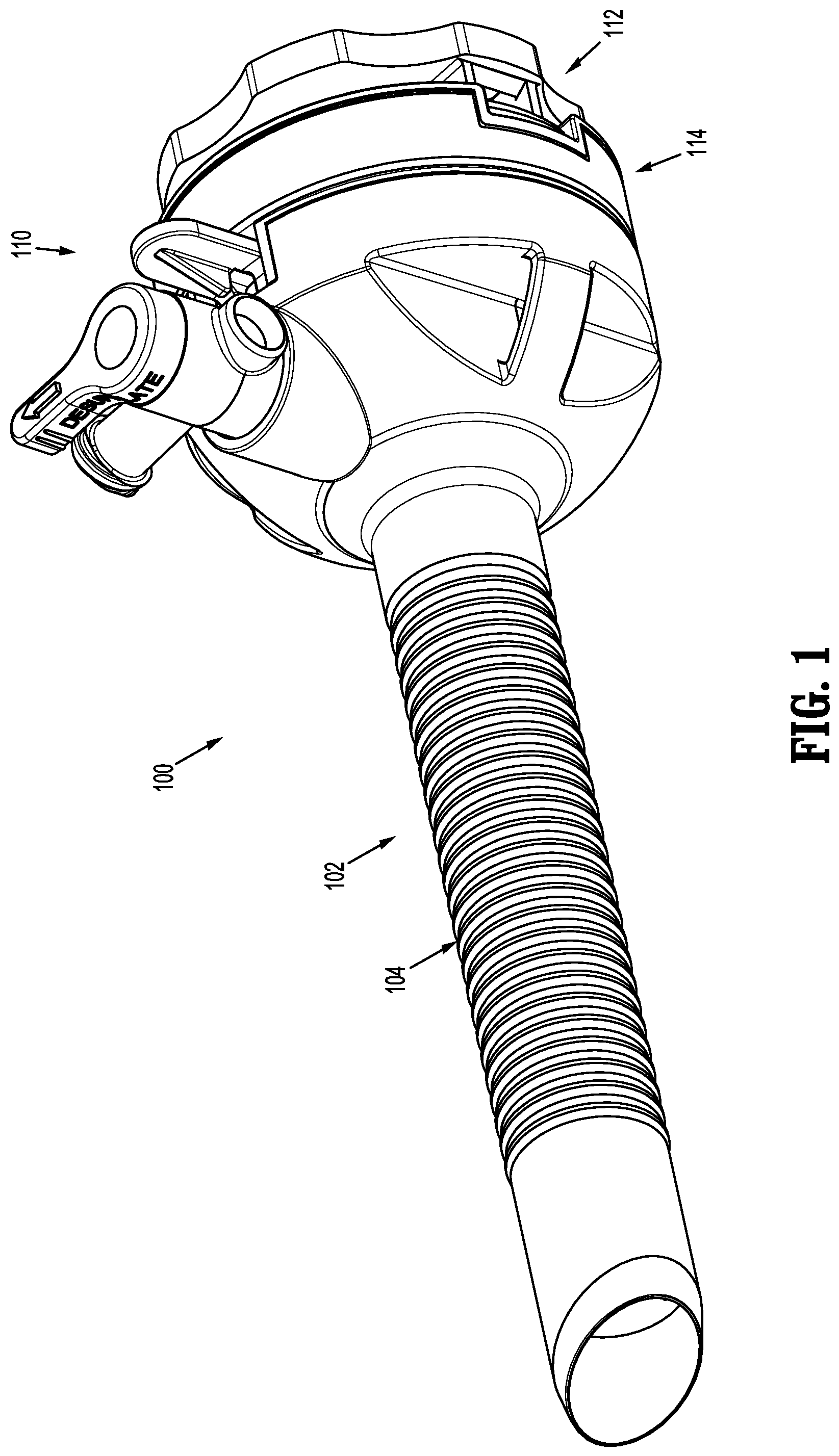
FIG. 1 is a perspective side view of a cannula of a trocar assembly according to an embodiment of the present disclosure;
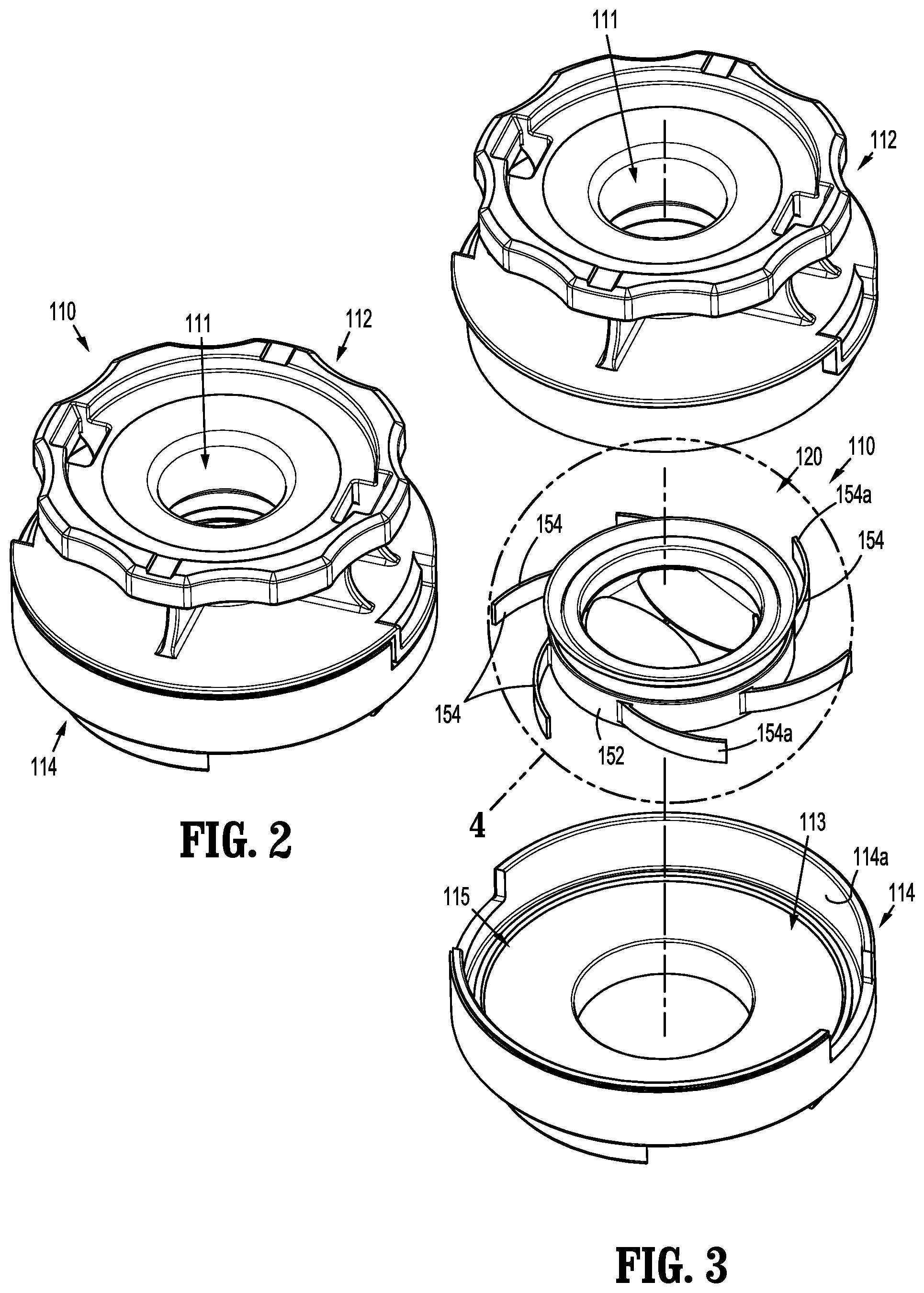
FIG. 2 is a perspective top view of an instrument valve housing of the cannula shown in FIG. 1;
FIG. 3 is an exploded top view of the instrument valve housing shown in FIG. 2, including first and second housing sections, separated, and a valve assembly;
FIG. 4 is a perspective top view of the valve assembly shown in FIG. 3;
FIG. 5 is a perspective top view of a plurality of guard members of a guard assembly of the valve assembly shown in FIG. 3;
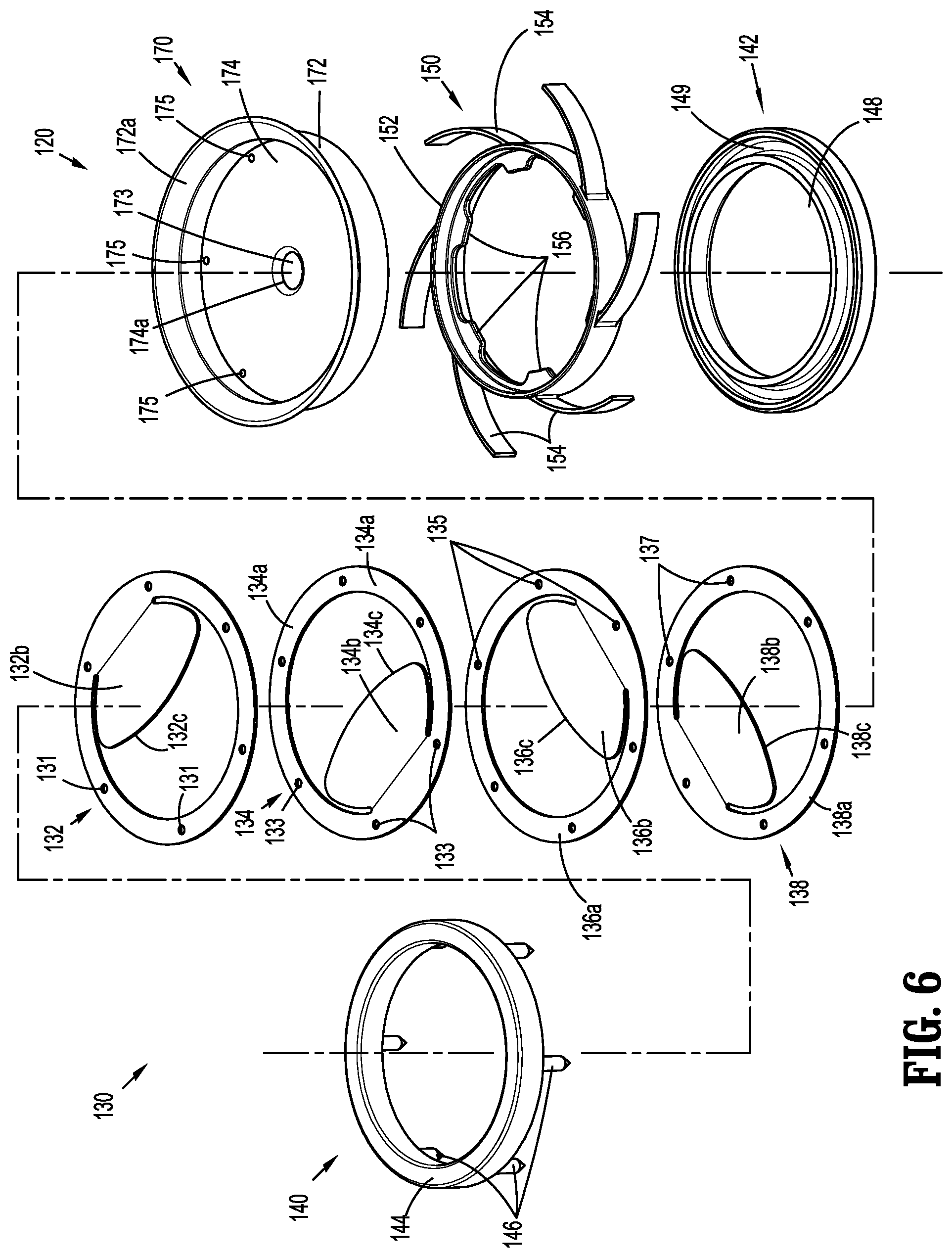
FIG. 6 is an exploded view of the valve assembly shown in FIG. 3, with parts separated;
FIG. 7 is a perspective top view of the plurality of guard members of the guard assembly shown in FIG. 3, with the guard members in an alternative configuration;
FIG. 8 is a perspective top view of a guard member according to another embodiment of the present disclosure, in an initial or pre-folded configuration;
FIG. 9 is a perspective top view of the guard member shown in FIG. 8, in a second or partially-folded configuration;
FIG. 10 is a perspective top view of the guard member shown in FIG. 8, in a fully-folded configuration;
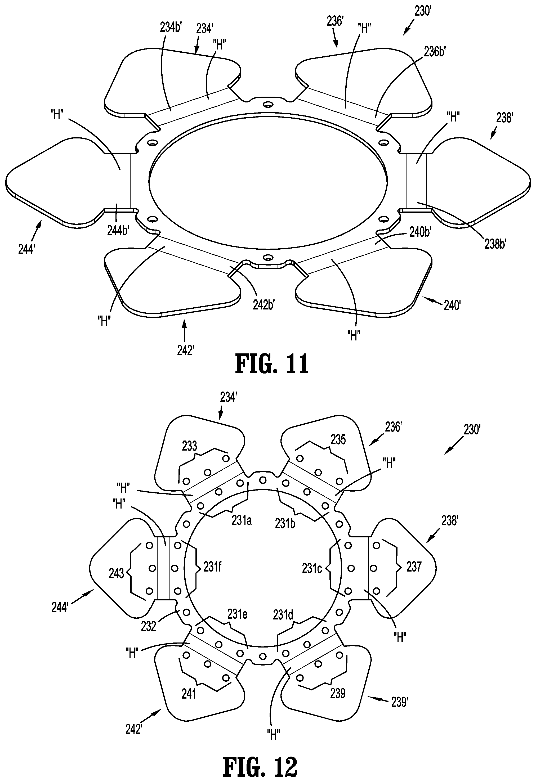
FIG. 11 is a perspective top view of a guard member according to yet another embodiment of the present disclosure; and
FIG. 12 is a top view of a guard member according to still another embodiment of the present disclosure.
DETAILED DESCRIPTION
Particular embodiments of the present disclosure are described hereinbelow with reference to the accompanying drawings; however, it is to be understood that the disclosed embodiments are merely exemplary of the disclosure and may be embodied in various forms. Well-known functions or constructions are not described in detail to avoid obscuring the present disclosure in unnecessary detail. Therefore, specific structural and functional details disclosed herein are not to be interpreted as limiting, but merely as a basis for the claims and as a representative basis for teaching one skilled in the art to variously employ the present disclosure in virtually any appropriately detailed structure. Like reference numerals refer to similar or identical elements throughout the description of the figures.
As used herein, the term "distal" refers to that portion of the instrument, or component thereof which is farther from the user while the term "proximal" refers to that portion of the instrument or component thereof which is closer to the user.
Cannulas are employed during, e.g., laparoscopic surgery and may, in various embodiments, provide for the sealed access of laparoscopic surgical instruments into an insufflated body cavity, such as the abdominal cavity. The cannulas of the present disclosure include an instrument valve housing mounted on a cannula tube. Cannulas are typically part of a trocar assembly including a trocar obturator. The trocar obturator is insertable through the cannula to facilitate placement of the cannula through tissue. The cannula and the trocar obturator are separate components but are capable of being selectively connected together. For example, the trocar obturator may be inserted into and through the cannula until the handle of the trocar obturator engages, e.g., selectively locks into, the instrument valve housing of the cannula.
Trocar assemblies are employed to tunnel through an anatomical structure, e.g., the abdominal wall, either by making a new passage through the structure or by passing through an existing opening through the structure. Once the trocar assembly has tunneled through the anatomical structure, the trocar obturator is removed, leaving the cannula in place in the structure, e.g., in the incision created by the trocar assembly. The instrument valve housing of the cannula may include valves that prevent the escape of insufflation gases from the body cavity, while also allowing surgical instruments to be inserted into the cavity.
In various embodiments, a bladeless optical trocar obturator may be provided that permits separation of tissue planes in a surgical procedure and visualization of body tissue fibers as they are being separated, thereby permitting a controlled traversal across a body wall. In other embodiments, the trocar obturator may be bladeless without being optical, e.g., without providing contemporaneous visualization thereof through the distal tip of an obturator. The bladeless obturator may be provided for the blunt dissection of the abdominal lining during a surgical procedure.
Various trocar obturators suitable for use with the cannulas of the present disclosure are known and include, for example, bladed, bladeless, blunt, optical, non-optical. The trocar assemblies will only be described to the extent necessary to disclose the aspects of the present disclosure. For a detailed description of the structure and function of exemplary trocar assemblies, including exemplar trocar obturators and exemplar cannulas, please refer to commonly owned PCT Publication No WO 2016/186905 ("the '905 publication"), the content of which is hereby incorporated by reference herein in its entirety.
With initial reference now to FIG. 1, a cannula according to aspects of the present disclosure is shown generally as cannula 100. The cannula 100 includes a cannula assembly 102 and an instrument valve housing 110 secured to the cannula assembly 102. The cannula assembly 102 will only be described to the extent necessary to fully disclose the aspects of the present disclosure. For a detailed description of an exemplary cannula assembly, please refer to the '905 publication.
With reference to FIGS. 2 and 3, the instrument valve housing 110 of the cannula 100 includes a first housing section 112 and a second housing section 114. The first and second housing section 112, 114 are configured to support a valve assembly 120 on a proximal end of the cannula assembly 102. More particularly, the first and second housing sections 112, 114 define a cavity 113 for operably receiving the valve assembly 120. The first housing section 112 of the instrument valve housing 110 may be selectively attachable to, and detachable from, the second housing section 114. The second housing section 114 may be releasably or permanently attached to a cannula tube 104 of the cannula assembly 102. In embodiments, either or both of the first and second housing sections 112, 114 of the instrument valve housing 110 may include knurls, indentations, tabs, or be otherwise configured to facilitate engagement by a clinician.
The first and second housing sections 112, 114 of the instrument valve housing 110 define a longitudinal passage 111 for receipt of a surgical instrument (not shown). The valve assembly 120 is supported within the first and second housing sections 112, 114 to provide sealed passage of the surgical instrument through the instrument valve housing 110.
With particular reference to FIGS. 4-6, the valve assembly 120 supported in the instrument valve housing 110 includes a guard assembly 130, a centering mechanism 150, and a seal assembly 170. As will be described in further detail below, the guard assembly 130 is configured to protect the seal assembly 170 during insertion and withdrawal of a surgical instrument through the seal assembly 170. The centering mechanism 150 is configured to permit radial movement of the valve assembly 120 relative to the instrument valve housing 110 when a surgical instrument is received through the valve assembly 120, and returns the valve assembly 120 to a centered position once the surgical instrument is withdrawn from within the instrument valve housing 120. The seal assembly 170 provides sealed passage of the surgical instrument through the instrument valve housing 110.
The guard assembly 130 of the valve assembly 120 supported within the instrument valve housing 110 includes first, second, third, and fourth guard members 132, 134, 136, 138. The guard members 132, 134, 136, 138 are formed of rigid plastic or other suitable material. Each of the first, second, third, and fourth guard members 132, 134, 136, 138 includes a ring portion 132a, 134a, 136a, 138a and a flap portion 132b, 134b, 136b, 138b. The ring portions 132a, 134a, 136a, 138a of the first, second, third, and fourth guard members 132, 134, 136, 138 each define a plurality of openings 131, 133, 135, 137, respectively. Each opening of the plurality of openings 131, 133, 135, 137 is configured to receive a pin of a plurality of pins 146 of an upper retainer member 140.
Each of the flap portions 132b, 134b, 136b, 138b of the respective first, second, third, and fourth guard members 132, 134, 136, 138 of the guard assembly 130 extends radially inward from the ring portions 132a, 134a, 136a, 138a. Each of the flap portions 132b, 134b, 136b, 138b includes a substantial mushroom cap shape having a curved outer edge 132c, 134c, 136c, 138c. The flap portions 132b, 134b, 136b, 138b do not extend beyond a midline of the respective first, second, third, and fourth guard members 132, 134, 136, 138, e.g., midline "y" of the first and second guard members 132, 134 and midline "z" of the third and fourth guard members 136, 138, shown in FIG. 5).
As shown in FIGS. 5 and 6, the first, second, third, and fourth guard members 132, 134, 136, 138 are arranged one on top of another, e.g., stacked configuration. As shown, the first and second guard members 132, 134 are arranged such that the respective flap portions 132b, 134b are opposed to one another and do not overlap. The first and second flap portions 132b, 134b form a first layer occupying a majority of the opening 139 defined by the ring portions 132a, 134a of the respective first and second guard members 132, 134. Similarly, the third and fourth guard members 136, 138 are arranged such that the respective flap portions 136b, 138b are opposed to one another and do not overlap. The third and fourth flap portions 136b, 138b of the third and fourth guard members 136, 138 form a second layer occupying a majority of the opening 139 defined by the ring portions 136a, 138a of the respective third and fourth guard members 136, 138.
As shown in FIG. 5, are offset by ninety degrees (90.degree.) relative to each other. In this manner, first and second guard members 132, 134 are perpendicular to the third and fourth guard members 136, 138, and together, occupy nearly the entire opening 139 defined by the ring portions 132a, 134a, 136a, 138a. The flap portions 132b, 134b, 136b, 138b of the respective first, second, third and fourth guard members 132, 134, 136, 138 are configured to flex downward upon engagement with a surgical instrument to facilitate passage of the surgical instrument through seal assembly 170. More particularly, engagement of the first and second flap portions 132b, 134b of the first and second guard members 132, 134, respectively, flexes the first and second flap portions 132b, 134b downward into engagement with the third and fourth flap portions 136b, 138b of the third and fourth guard members 136, 138. Continued insertion of the surgical instrument through the guard assembly 130 causes each of the first, second, third, and fourth flap portions 132b, 134b, 136b, 138b to engage with a septum seal 174 of the seal assembly 170 to stretch the septum seal 174 of the seal assembly 170 to increase the size of a central opening 173 of the septum seal 174. The increased size of the central opening 173 the septum seal 174 permits receipt of the surgical instrument through the valve assembly 120. The larger the diameter of the surgical instrument, the more the first, second, third, and fourth flap portions 132b, 134b, 136b, 138b of the first, second, third, and fourth guard members 132, 134, 136, 138 are flexed downward and the greater the size of the central opening 173 in the septum seal 174. The flap portions 132b, 134b, 136b, 138b guide and center the surgical instrument through the septum seal 174. In addition, the flap portions 132b, 134b, 136b, 138b may also inhibit inversion of the seal assembly 170 during withdrawal of a surgical instrument from the seal assembly 170.
It is envisioned that the guard assembly 130 may include a guard member (not shown) including a pair of opposed flap portions (not shown) supported on a single ring portion. In embodiments, the flap portions may extend radially outward from the ring portions, thereby necessitating folding the flap portions over the ring portions. See, for example, the embodiment of FIG. 8. The guard assembly may include any number of guard members, and the guard members may include flap portions of any size or configuration.
Turning briefly to FIG. 7, in an alternative embodiment of the guard assembly 130', the flap portions 132b', 134b', 136b', 138b' of the respective first, second, third and fourth guard members 132', 134', 136', 138' overlap with one another. More particularly, the first flap portion 132b' of the first guard member 132' overlaps the third flap portion 136b' of the third guard member 136', the third flap portion 136b' of the third guard member 136 overlaps the second flap portion 134b' of the second guard member 134', the second flap portion 134b' of the second guard member 134' overlaps the fourth flap portion 138b of the fourth guard member 138', and the fourth flap portion 138b' of the fourth guard member 138 overlaps the first flap portion 132b' of the first guard member 132'.
With reference again to FIG. 6, the guard assembly 130 further includes upper and lower retainer members 140, 142 for retaining the first, second, third and fourth guard members 132, 134, 136, 138. More particularly, the upper retainer member 140 includes a base 144 and the plurality of fingers or pins 146 extending downwardly from the base 144. The lower retainer member 142 includes a base 148 defining an annular channel 149 for securely receiving the plurality of pins 146 of the upper retainer member 140.
Although the plurality of pins 146 is shown as extending downwardly from the base 144 of the upper retainer member 140 for engagement with the lower retainer member 142, in other embodiments, the plurality of pins 146 may instead extend upwardly from the base 148 of the lower retainer member 142 for engagement with the upper retainer member 140, or the pins 146 may extend from both the upper and lower retainer members 140, 142 and extend both upwardly and downwardly. In addition, while the lower retainer member 142 is shown and described as including the annular channel 149, the lower retainer member 142 may instead include one or more discrete openings (not shown) for receiving the corresponding fingers or pins, which may improve the engagement of the pins 146 with the lower retainer member 142 and increase the retention between the pins 146 and the lower retainer member 142 once the upper and lower retainer members 140, 142 are connected to each other. Employing the channel 149 instead of the discrete openings eliminates the need to circumferential align the upper and lower retainer members 140, 142 prior to connecting the upper and lower retainer members 140, 142 to one another.
The plurality of pins 146 of the upper retainer member 140 of the guard assembly 130 are configured to be received through the plurality of openings 131, 133, 135, 137 in the respective ring portions 132a, 134a, 136a, 138a of the first, second, third, and fourth guard members 132, 134, 136, 138, respectively. Receipt of the plurality of pins 146 of the upper retainer member 140 of the guard assembly 130 through the plurality of openings 131, 133, 135, 137 in the respective first, second, third, and fourth guard members 132, 134, 136, 138 and subsequent attachment of the lower retainer member 142 to the upper retainer member 140 secures the first, second, third, and fourth guard members 132, 134, 136, 138 relative to one another. The upper and lower retainer members 140, 142 of the guard assembly 130 also secure the guard assembly 130 and seal assembly 170 the centering mechanism 150.
With particular reference to FIGS. 4 and 6, the centering mechanism 150 of the instrument valve housing 110 is configured to maintain the valve assembly 110 centered within the cavity 113 of the first and second housing sections 112, 114 of the instrument valve housing 110 (FIG. 3). More particularly, the centering mechanism 150 includes an annular ring 152 and a plurality of spokes or spring elements 154 extending radially outward from the annular ring 152. The centering mechanism 150 further includes a plurality of tabs 156 that extend inwardly from the annular ring 152 and are configured to engage the seal member 170. For a detailed description of the structure and function of an exemplary centering mechanism, please refer to commonly owned U.S. Pat. App. Pub. No. 2015/0025477 ("the '477 publication"), the content of which is incorporated herein by reference in its entirety. It is envisioned that the centering mechanism 150 may include two centering mechanisms, as disclosed in the '477 publication.
As described in the '477 publication, the plurality of spokes 154 of the centering mechanism 150 each include a free end 154a configured to engage an inner wall 114a (FIG. 3) of the lower housing section 114 when the valve assembly 120 is moved off-center to bias the valve assembly 120 back to a centered position.
Alternatively, the centering mechanism may include a bellows or otherwise be configured to maintain the valve assembly 120 centered within the instrument valve housing 110.
Referring again to FIG. 6, the seal member 170 of the valve assembly 120 is configured to provide a seal around an outer surface of a surgical instrument passing through the instrument valve housing 110. The seal member 170 includes an annular flange 172, and the septum seal 174 supported by the annular flange 172. As shown, a free end 172a of the annular flange 172 may extend radially outwardly and in a proximal direction to facilitate reception of a surgical instrument through the septum seal 174.
The septum seal 174 of the seal member 170 is formed of an elastic material, e.g., rubber, and defines a central opening 173. In embodiments, the septum seal 174 may include one or more fabric layers. The septum seal 174 is configured to provide a seal around an outer surface of a surgical instrument passing through the valve assembly 120. A surface 174a of the septum seal 174 defining the central opening 173 may be beveled or otherwise configured to facilitate reception of the surgical instrument through the central opening 173 in the septum seal 174. The septum seal 174 further defines a plurality of openings 175 corresponding to the pins 146 extending from the upper retainer member 140 of the guard assembly 130.
With particular reference to FIG. 4, the upper retainer member 140 of the guard assembly 130 of the valve assembly 120 is received within the annular flange 172 of the seal member 170 such that the pins 146 of the upper retainer member 140 are received through the openings 175 (FIG. 6) in the septum seal 174 of the seal member 170. Prior to receiving the pins 146 of the upper retainer member 140 through the openings 175 in the septum seal 174, the first, second, third and fourth guard members 132, 134, 136, 138 of the guard assembly 130 are secured to the upper retainer member 140. In this manner, when the pins 146 of the upper retainer member 140 are received through the openings 175 in the septum seal 174, the first, second, third, and fourth guard members 132, 134, 136, 138 of the guard assembly 130 are disposed within the annular flange 172 of the seal assembly 170. The lower retainer member 142 of the guard assembly 130 is secured to the upper retainer member 140 to secure the first, second, third, and fourth guard members 132, 134, 136, 138 relative to the seal assembly 170. The upper and lower retainer members 140, 142 also maintain alignment and orientation of the first, second, third, and fourth guard members 132, 134, 136, 138.
In an assembled configuration, the seal assembly 170, including the guard assembly 130, is received within the annular ring 152 of the centering mechanism 150. More particularly, the tabs 156 (FIG. 6) extending inwardly from the annular ring 152 of the center mechanism 150 engage an outer surface of the annular flange 172 to maintain the seal assembly 170 within the centering mechanism 150.
During a surgical procedure utilizing cannula 100, an instrument (not shown) is introduced into the instrument valve housing 110 through the longitudinal passage 113 in the first and second housing sections 112, 114. As described above, the distal end of the instrument engages the first and second flap portions 132b, 134b of the respective first and second guard members 132, 134. The first and second flap portions 132b, 134b flex downward into contact with the third and fourth flap portions 136b, 138b of the respective third and fourth guard members 136, 138. The first, second, third and fourth flap portions 132b, 134b, 136b, 138b flex into contact with the septum seal 174 of the seal member 170 to cause the central opening 173 of the septum seal 174 to open to accommodate passage of the surgical instrument through the septum seal 174. The first, second, third, and fourth guard members 132, 134, 136, 138 of the guard assembly 130 minimize damage to the seal member 170 during insertion of an instrument through the valve assembly 120.
The first, second, third, and fourth guard members 132, 134, 136, 138 of the guard assembly 130 operate to protect the septum seal 174 of the seal assembly 170 from tearing or other damage as a surgical instrument is received through the seal assembly 170. Additionally, the guard assembly 130 may prevent inversion of the septum seal 174 as the surgical instrument is retracted through the septum seal 174.
With reference now to FIGS. 8-10, a guard member according to another embodiment of the present disclosure is shown generally as guard member 230. The guard member 230 includes a ring portion 232 and first, second, third, fourth, fifth, and sixth petals 234, 236, 238, 240, 242, 244 supported by and extending radially outward from the ring portion 232 when the guard member 230 is in an initial or pre-folded condition (FIG. 8).
The ring portion 232 of the guard member 230 defines a plurality of openings 233 to facilitate engagement of the guard member 230 by retainer members, e.g., the upper and lower retainer members 140, 142 (FIG. 6). The ring portion 232 may define one or more openings corresponding to the first, second, third, fourth, fifth, and sixth petals 234, 236, 238, 240, 242, 244. In embodiments, and as will be described in further detail below, the plurality of petals may also each define one or more openings (FIG. 12) corresponding to openings in the ring portions when the petals are in a fully-folded condition (FIG. 10).
Each of the first, second, third, fourth, fifth, and sixth petals 234, 236, 238, 240, 242, 244 of the guard member 230 includes a flap portion 234a, 236a, 238a, 240a, 242a, 244a and a connector portion 234b, 236b, 238b, 240b, 242b, 244b connecting the flap portions 234a, 236a, 238a, 240a, 242a, 244a of the respective first, second, third, fourth, fifth, and sixth petals 234, 236, 238, 240, 242, 244 to the ring portion 232. In embodiments, and as shown, the flap portions 234a, 236a, 238a, 240a, 242a, 244a of the first, second, third, fourth, fifth, and sixth petals 234, 236, 238, 240, 242, 244, respectively, define a spade-like body, although other configurations are envisioned. Similarly, although shown having six (6) petals, it is envisioned that the guard member may have more or less than six (6) petals.
The connector portions 234b, 236b, 238b, 240b, 242b, 244b of the respective petals 234, 236, 238, 240, 242, 244 are configured to permit inward folding of the respective petals 234, 236, 238, 240, 242, 244 such that the flap portions 234a, 236a, 238a, 240a, 242a, 244a of the respective first, second, third, fourth, fifth, and sixth petals 234, 236, 238, 240, 242, 244 occupy substantially the entire opening 231 defined by the ring portion 232. In embodiments, and as shown, the first, second, third, fourth, fifth, and sixth petals 234, 236, 238, 240, 242, 244 are configured to overlap one another when folded, as described below. The connector portions 234b, 236b, 238b, 240b, 242b, 244b may provide increased stability and structure to the respective first, second, third, fourth, fifth, and sixth petals 234, 236, 238, 240, 242, 244.
Turning briefly to FIG. 11, in embodiments, connector portions 234b', 236b', 238b', 240b', 242b', 244b' of respective first, second, third, fourth, fifth, and sixth petals 234', 236', 238', 240', 242', 244' of a guard member 230' define a hinge feature "H" to facilitate folding of the respective first, second, third, fourth, fifth, and sixth petals 234', 236', 238', 240', 242', 244'. The hinge feature "H" may be a living hinge including a weakened or thinned portion of the connector portions 234b', 236b', 238b', 240b', 242b', 244b'. The hinge feature "H" may also facilitate orienting and aligning the first, second, third, fourth, fifth, and sixth petals 234', 236', 238', 240', 242', 244'.
With particular reference to FIG. 10, the first, second, third, fourth, fifth, and sixth petals 234, 236, 238, 240, 242, 244 of the guard member 230 are shown in a sequentially overlapping configuration. More particularly, the flap portion 234a of the first petal 234 overlaps the flap portion 236a of the second petal 236, which overlaps the flap portion 238a of the third petal 238, which overlaps the flap portion 240a of the fourth petal 240, which overlaps the flap portions 242a of the fifth petal 242, which overlaps the flap portion 244a of the sixth petal 244. In this manner, downward flexing of one of the flap portions 234, 236, 238, 240, 242, 244 during engagement by a surgical instrument causes downward flexing of all of the flap portions 234, 236, 238, 240, 242, 244.
Alternatively, the first, second, third, fourth, fifth, and sixth petals 234, 236, 238, 240, 242, 244 of the guard member 230 may be arranged in an alternating pattern. More particularly, the first, second, third, fourth, fifth, and sixth petals 234, 236, 238, 240, 242, 244 are arranged such that the second and sixth petals 236, 244 overlap the first petal 234, the second and fourth petals 236, 240 overlap the third petal 238, and the fourth and sixth petals 240, 244 overlap the fifth petal 242.
With reference to FIG. 12, in an alternative embodiment, a guard assembly 230' includes a ring portion 232' and first, second, third, fourth, fifth, and sixth petals 234', 236', 238', 240', 242', 244' each including a respective flap portion 234a', 236a', 238a', 240a', 242a', 244a'. Each of the flap portions 234a', 236a', 238a', 240a', 242a', 244a' defines one or more openings 233, 235, 237, 239, 241, 243 corresponding to one or more openings 231a, 231b, 231c, 231d, 231e, 231f in the ring portion 232'. The one or more openings 233, 235, 237, 239, 241, 243 of the respective of the flap portions 234a', 236a', 238a', 240a', 242a', 244a align with the corresponding one or more openings 231a, 231b, 231c, 231d, 231e, 231f in the ring portion 232' when the first, second, third, fourth, fifth, and sixth petals 234', 236', 238', 240', 242', 244' are in a folded configuration, e.g., FIG. 10.
The one or more openings 233, 235, 237, 239, 241, 243 of the first, second, third, fourth, fifth, and sixth petals 234', 236', 238', 240', 242', 244' are configured to receive pins, e.g., pins 146 (FIG. 6) of a retainer member, e.g., upper retainer member 140. Receipt of the pins through the one or more openings 233, 235, 237, 239, 241, 243 align the first, second, third, fourth, fifth, and sixth petals 234, 236, 238, 240, 242, 244 relative to each other and provide structure support to the guard member 230'.
While various embodiments of the present disclosure have been shown and described herein, it will be obvious to those skilled in the art that these embodiments are provided by way of example only. Numerous variations, changes, and substitutions will now occur to those skilled in the art without departing from the present disclosure. Accordingly, it is intended that the invention be limited only by the spirit and scope of the appended claims.
* * * * *
D00000
D00001
D00002
D00003
D00004
D00005
D00006
D00007
D00008
XML
uspto.report is an independent third-party trademark research tool that is not affiliated, endorsed, or sponsored by the United States Patent and Trademark Office (USPTO) or any other governmental organization. The information provided by uspto.report is based on publicly available data at the time of writing and is intended for informational purposes only.
While we strive to provide accurate and up-to-date information, we do not guarantee the accuracy, completeness, reliability, or suitability of the information displayed on this site. The use of this site is at your own risk. Any reliance you place on such information is therefore strictly at your own risk.
All official trademark data, including owner information, should be verified by visiting the official USPTO website at www.uspto.gov. This site is not intended to replace professional legal advice and should not be used as a substitute for consulting with a legal professional who is knowledgeable about trademark law.