System and method for creating or modifying a welding sequence based on non-real world weld data
Daniel , et al. May 4, 2
U.S. patent number 10,994,358 [Application Number 13/802,918] was granted by the patent office on 2021-05-04 for system and method for creating or modifying a welding sequence based on non-real world weld data. This patent grant is currently assigned to LINCOLN GLOBAL, INC.. The grantee listed for this patent is LINCOLN GLOBAL, INC.. Invention is credited to Joseph A. Daniel, Edward Enyedy, James Hearn, Judah Henry.


View All Diagrams
| United States Patent | 10,994,358 |
| Daniel , et al. | May 4, 2021 |
System and method for creating or modifying a welding sequence based on non-real world weld data
Abstract
The invention described herein generally pertains to a system and method for welder system that relates to creating a welding sequence for a welding environment in which the welding sequence is based upon non-real time data collected from a welding procedure. Welding procedure information is collected and utilized to create a welding sequence to perform two or more welds in which at least one parameter is based on the collected welding procedure information (e.g., non-real world welding procedure).
| Inventors: | Daniel; Joseph A. (Sagamore Hills, OH), Enyedy; Edward (Eastlake, OH), Hearn; James (Brunswick, OH), Henry; Judah (Geneva, OH) | ||||||||||
|---|---|---|---|---|---|---|---|---|---|---|---|
| Applicant: |
|
||||||||||
| Assignee: | LINCOLN GLOBAL, INC. (City Of
Industry, CA) |
||||||||||
| Family ID: | 1000005528102 | ||||||||||
| Appl. No.: | 13/802,918 | ||||||||||
| Filed: | March 14, 2013 |
Prior Publication Data
| Document Identifier | Publication Date | |
|---|---|---|
| US 20140263226 A1 | Sep 18, 2014 | |
| US 20160361774 A9 | Dec 15, 2016 | |
Related U.S. Patent Documents
| Application Number | Filing Date | Patent Number | Issue Date | ||
|---|---|---|---|---|---|
| 11613652 | Aug 11, 2015 | 9104195 | |||
| Current U.S. Class: | 1/1 |
| Current CPC Class: | B23K 9/0953 (20130101) |
| Current International Class: | B23K 9/12 (20060101); B23K 9/095 (20060101) |
| Field of Search: | ;219/125.1,130.01,130.1,130.5,130.51,130.21,137R,137.2,137.71 ;228/102 ;2/8.2 ;700/182 |
References Cited [Referenced By]
U.S. Patent Documents
| 1159119 | November 1915 | Springer |
| D140630 | March 1945 | Garibay |
| D142377 | September 1945 | Dunn |
| D152049 | December 1948 | Alanson |
| 2681969 | June 1954 | Burke |
| D174208 | March 1955 | Abildgaard |
| 2728838 | December 1955 | Barnes |
| D176942 | February 1956 | Cross |
| 2894086 | July 1959 | Rizer |
| 3035155 | May 1962 | Hawk |
| 3059519 | October 1962 | Stanton |
| 3356823 | December 1967 | Waters et al. |
| 3555239 | January 1971 | Kerth |
| 3581051 | May 1971 | Brown et al. |
| 3621177 | November 1971 | McPherson et al. |
| 3654421 | April 1972 | Streetman et al. |
| 3689734 | September 1972 | Burley et al. |
| 3739140 | June 1973 | Rotilio |
| 3847584 | November 1974 | Houser |
| 3866011 | February 1975 | Cole |
| 3867769 | February 1975 | Schow et al. |
| 3904845 | September 1975 | Minkiewicz |
| 3988913 | November 1976 | Metcalfe et al. |
| D243459 | February 1977 | Bliss |
| 4024371 | May 1977 | Drake |
| 4041615 | August 1977 | Whitehill |
| D247421 | March 1978 | Driscoll |
| 4104724 | August 1978 | Dix et al. |
| 4124944 | November 1978 | Blair |
| 4132014 | January 1979 | Schow |
| 4145593 | March 1979 | Merrick et al. |
| 4153913 | May 1979 | Swift |
| 4237365 | December 1980 | Lambros et al. |
| 4280041 | July 1981 | Kiessling et al. |
| 4280137 | July 1981 | Ashida et al. |
| 4314125 | February 1982 | Nakamura |
| 4324973 | April 1982 | Kirwan et al. |
| 4359622 | November 1982 | Dostoomian et al. |
| 4375026 | February 1983 | Kearney |
| 4380696 | April 1983 | Masaki |
| 4390954 | June 1983 | Manning |
| 4410787 | October 1983 | Kremers et al. |
| 4419560 | December 1983 | Zurek |
| 4419562 | December 1983 | Jon et al. |
| 4429266 | January 1984 | Tradt |
| 4452589 | June 1984 | Denison |
| 4459457 | July 1984 | Jurek |
| D275292 | August 1984 | Bouman |
| 4477713 | October 1984 | Cook et al. |
| 4484059 | November 1984 | Lillquist |
| 4497019 | January 1985 | Waber |
| D277761 | February 1985 | Korovin et al. |
| 4527045 | July 1985 | Nakajima |
| D280329 | August 1985 | Bouman |
| 4611111 | September 1986 | Baheti et al. |
| 4616326 | October 1986 | Meier et al. |
| 4629860 | December 1986 | Lindbom |
| 4631700 | December 1986 | Lapeyre |
| 4677277 | June 1987 | Cook et al. |
| 4680014 | July 1987 | Paton et al. |
| 4681999 | July 1987 | Hruska |
| 4689021 | August 1987 | Vasiliev et al. |
| 4707582 | November 1987 | Beyer |
| 4716273 | December 1987 | Paton et al. |
| D297704 | September 1988 | Bulow |
| 4785159 | November 1988 | Hruska |
| 4867685 | September 1989 | Brush et al. |
| 4877940 | October 1989 | Bangs et al. |
| 4881678 | November 1989 | Gaudin |
| 4897521 | January 1990 | Burr |
| 4907973 | March 1990 | Hon |
| 4920248 | April 1990 | Toyoda et al. |
| 4931018 | June 1990 | Herbst et al. |
| 4998050 | March 1991 | Nishiyama et al. |
| 5034593 | July 1991 | Rice et al. |
| 5061841 | October 1991 | Richardson |
| 5081338 | January 1992 | Dufrenne |
| 5089914 | February 1992 | Prescott |
| 5192845 | March 1993 | Kirmsse et al. |
| 5206472 | April 1993 | Myking et al. |
| 5206474 | April 1993 | Fukuoka |
| 5265787 | November 1993 | Ishizaka et al. |
| 5266930 | November 1993 | Ichikawa et al. |
| 5278390 | January 1994 | Blankenship |
| 5285916 | February 1994 | Ross |
| 5305183 | April 1994 | Teynor |
| 5306893 | April 1994 | Morris et al. |
| 5320538 | June 1994 | Baum |
| 5337611 | August 1994 | Fleming et al. |
| 5360156 | November 1994 | Ishizaka et al. |
| 5360960 | November 1994 | Shirk |
| 5380978 | January 1995 | Pryor |
| D359296 | June 1995 | Witherspoon |
| 5424634 | June 1995 | Goldfarb et al. |
| 5436638 | July 1995 | Bolas et al. |
| 5449877 | September 1995 | Buda et al. |
| 5450315 | September 1995 | Stefanski |
| 5464957 | November 1995 | Kidwell et al. |
| 5467957 | November 1995 | Gauger |
| D365583 | December 1995 | Viken |
| 5474225 | December 1995 | Geier et al. |
| 5493093 | February 1996 | Cecil |
| 5532452 | July 1996 | Lechner |
| 5533206 | July 1996 | Petrie et al. |
| 5562843 | October 1996 | Yasumoto |
| 5651903 | July 1997 | Shirk |
| 5670071 | September 1997 | Ueyama et al. |
| 5676503 | October 1997 | Lang |
| 5676867 | October 1997 | Van Allen |
| 5708253 | January 1998 | Bloch et al. |
| 5710405 | January 1998 | Solomon et al. |
| 5719369 | February 1998 | White et al. |
| D392534 | March 1998 | Degen et al. |
| 5728991 | March 1998 | Takada et al. |
| 5734421 | March 1998 | Maguire, Jr. |
| 5751258 | May 1998 | Fergason et al. |
| D395296 | June 1998 | Kaye et al. |
| 5773779 | June 1998 | Morlock |
| D396238 | July 1998 | Schmitt |
| 5781258 | July 1998 | Dabral et al. |
| 5823785 | October 1998 | Matherne, Jr. |
| 5835077 | November 1998 | Dao et al. |
| 5835277 | November 1998 | Hegg |
| 5837968 | November 1998 | Rohrberg et al. |
| 5845053 | December 1998 | Watanabe et al. |
| 5850066 | December 1998 | Dew et al. |
| 5859847 | January 1999 | Dew et al. |
| 5866866 | February 1999 | Shimada |
| 5877468 | March 1999 | Morlock |
| 5906761 | May 1999 | Gilliland |
| 5910894 | June 1999 | Pryor |
| 5949388 | September 1999 | Atsumi et al. |
| 5963891 | October 1999 | Walker et al. |
| 6002104 | December 1999 | Hsu |
| 6008470 | December 1999 | Zhang et al. |
| 6023044 | February 2000 | Kosaka et al. |
| 6049059 | April 2000 | Kim |
| 6051805 | April 2000 | Vaidya et al. |
| 6063458 | May 2000 | Robertson et al. |
| 6087627 | July 2000 | Kramer |
| 6114645 | September 2000 | Burgess |
| 6115273 | September 2000 | Geisler |
| RE36926 | October 2000 | Austin |
| 6133545 | October 2000 | Okazaki |
| 6151640 | November 2000 | Buda et al. |
| 6155475 | December 2000 | Ekelof et al. |
| 6155928 | December 2000 | Burdick |
| 6167328 | December 2000 | Takaoka et al. |
| 6230327 | May 2001 | Briand et al. |
| 6236013 | May 2001 | Delzenne |
| 6236017 | May 2001 | Smartt |
| 6242711 | June 2001 | Cooper |
| 6271500 | August 2001 | Hirayama et al. |
| 6278074 | September 2001 | Molock et al. |
| 6292715 | September 2001 | Rongo |
| 6330938 | December 2001 | Herve et al. |
| 6330966 | December 2001 | Eissfeller |
| 6331848 | December 2001 | Stove et al. |
| D456428 | April 2002 | Aronson, II et al. |
| 6373465 | April 2002 | Jolly et al. |
| D456828 | May 2002 | Aronson, II et al. |
| 6399912 | June 2002 | Steenis et al. |
| D461383 | August 2002 | Blackburn |
| 6441342 | August 2002 | Hsu |
| 6444942 | September 2002 | Kawai et al. |
| 6445964 | September 2002 | White et al. |
| 6492618 | December 2002 | Flood et al. |
| 6506997 | January 2003 | Matsuyama |
| 6548783 | April 2003 | Kilovsky et al. |
| 6552303 | April 2003 | Blankenship |
| 6560029 | May 2003 | Dobbie et al. |
| 6563489 | May 2003 | Latypov et al. |
| 6568846 | May 2003 | Cote et al. |
| D475726 | June 2003 | Suga et al. |
| 6572379 | June 2003 | Sears et al. |
| 6583386 | June 2003 | Ivkovich |
| 6621049 | September 2003 | Suzuki |
| 6624388 | September 2003 | Blankenship |
| 6636776 | October 2003 | Barton et al. |
| D482171 | November 2003 | Vui et al. |
| 6644645 | November 2003 | Bakodledis |
| 6647288 | November 2003 | Madill et al. |
| 6649858 | November 2003 | Wakeman |
| 6655645 | December 2003 | Lu et al. |
| 6660965 | December 2003 | Simpson |
| 6697701 | February 2004 | Hillen et al. |
| 6697770 | February 2004 | Nagetgaal |
| 6700097 | March 2004 | Hsu et al. |
| 6703585 | March 2004 | Suzuki |
| 6708385 | March 2004 | Lemelson |
| 6710298 | March 2004 | Eriksson |
| 6710299 | March 2004 | Blankenship et al. |
| 6715502 | April 2004 | Rome et al. |
| 6717108 | April 2004 | Hsu |
| D490347 | May 2004 | Meyers |
| 6730875 | May 2004 | Hsu |
| 6734393 | May 2004 | Friedl et al. |
| 6734394 | May 2004 | Hsu |
| 6744011 | June 2004 | Hu et al. |
| 6747247 | June 2004 | Holverson |
| 6750428 | June 2004 | Okamoto et al. |
| 6768974 | July 2004 | Nakano et al. |
| 6772802 | August 2004 | Few |
| 6788442 | September 2004 | Potin et al. |
| 6795778 | September 2004 | Dodge et al. |
| 6798974 | September 2004 | Nakano et al. |
| 6822195 | November 2004 | Kanodia et al. |
| 6847956 | January 2005 | Manicke et al. |
| 6857553 | February 2005 | Hartman et al. |
| 6858817 | February 2005 | Blankenship et al. |
| 6865926 | March 2005 | O'Brien et al. |
| D504449 | April 2005 | Butchko |
| 6847922 | April 2005 | Wampter, II |
| 6912447 | June 2005 | Klimko et al. |
| 6920371 | July 2005 | Hillen et al. |
| 6924459 | August 2005 | Spear et al. |
| 6930280 | August 2005 | Zauner et al. |
| 6940039 | September 2005 | Blankenship et al. |
| 6995665 | February 2006 | Appelt et al. |
| 7021937 | April 2006 | Simpson et al. |
| 7028882 | April 2006 | Kilovsky et al. |
| 7030334 | April 2006 | Ruiz et al. |
| 7032814 | April 2006 | Blankenship |
| 7072774 | July 2006 | Houston |
| 7102098 | September 2006 | Rouault et al. |
| 7126078 | October 2006 | Demers et al. |
| 7132617 | November 2006 | Lee et al. |
| 7170032 | January 2007 | Flood |
| 7194447 | March 2007 | Harvey et al. |
| 7247814 | July 2007 | Ott |
| D555446 | November 2007 | Picaza Ibarrondo |
| 7315241 | January 2008 | Daily et al. |
| D561973 | February 2008 | Kinsley et al. |
| 7353715 | April 2008 | Myers |
| 7358458 | April 2008 | Daniel |
| 7363137 | April 2008 | Brant et al. |
| 7375304 | May 2008 | Kainec et al. |
| 7381923 | June 2008 | Gordon et al. |
| 7414595 | August 2008 | Muffler |
| 7465230 | December 2008 | LeMay et al. |
| 7478108 | January 2009 | Townsend et al. |
| D587975 | March 2009 | Aronson, II et al. |
| 7515972 | April 2009 | Kumar et al. |
| 7516022 | April 2009 | Lee et al. |
| 7523069 | April 2009 | Friedl |
| 7534005 | May 2009 | Buckman |
| 7539603 | May 2009 | Subrahmanyam |
| 7575304 | August 2009 | Sugahara |
| D602057 | October 2009 | Osicki |
| 7603191 | October 2009 | Gross |
| 7617017 | November 2009 | Menassa et al. |
| 7621171 | November 2009 | O'Brien |
| D606102 | December 2009 | Bender et al. |
| 7642486 | January 2010 | Fosbinde et al. |
| 7643890 | January 2010 | Hillen et al. |
| 7643907 | January 2010 | Fuhlbrigge et al. |
| 7687741 | March 2010 | Kainec et al. |
| D614217 | April 2010 | Peters et al. |
| D615573 | May 2010 | Peters et al. |
| 7772524 | August 2010 | Hillen et al. |
| 7809534 | October 2010 | Sturrock |
| 7817162 | October 2010 | Bolick et al. |
| 7853645 | December 2010 | Brown et al. |
| D631074 | January 2011 | Peters et al. |
| 7874921 | January 2011 | Baszucki et al. |
| 7962967 | June 2011 | Becker et al. |
| 7970172 | June 2011 | Hendrickson |
| 7972129 | July 2011 | O'Donoghue |
| 7991587 | August 2011 | Ihn |
| 8049139 | November 2011 | Houston |
| 8069017 | November 2011 | Hallquist |
| 8115138 | February 2012 | Jacovetty et al. |
| 8224881 | July 2012 | Spear |
| 8248324 | August 2012 | Nangle |
| 8265886 | September 2012 | Bisiaux et al. |
| 8274013 | September 2012 | Wallace |
| 8287522 | October 2012 | Moses et al. |
| 8312060 | November 2012 | Gilbert et al. |
| 8316462 | November 2012 | Becker et al. |
| 8322591 | December 2012 | Diez et al. |
| 8363048 | January 2013 | Gering |
| 8365603 | February 2013 | Lesage et al. |
| 8502866 | August 2013 | Becker et al. |
| 8512043 | August 2013 | Choquet |
| 8569646 | October 2013 | Daniel et al. |
| 8569655 | October 2013 | Cole |
| 8592723 | November 2013 | Davidson et al. |
| 8777629 | July 2014 | Kreindl et al. |
| RE45062 | August 2014 | Maguire, Jr. |
| 8860760 | October 2014 | Chen et al. |
| 8884177 | November 2014 | Daniel et al. |
| 9089921 | July 2015 | Daniel et al. |
| 9104195 | August 2015 | Daniel et al. |
| 9323056 | April 2016 | Williams |
| 9937577 | April 2018 | Daniel et al. |
| 2001/0045808 | November 2001 | Hietmann et al. |
| 2001/0052893 | December 2001 | Jolly et al. |
| 2002/0032553 | March 2002 | Simpson et al. |
| 2002/0046999 | April 2002 | Veikkolainen et al. |
| 2002/0050984 | May 2002 | Roberts |
| 2002/0085843 | July 2002 | Mann |
| 2002/0107825 | August 2002 | Manicke et al. |
| 2002/0117487 | August 2002 | Corby, Jr. et al. |
| 2002/0175897 | November 2002 | Pelosi |
| 2003/0000931 | January 2003 | Ueda et al. |
| 2003/0023592 | January 2003 | Modica et al. |
| 2003/0025884 | February 2003 | Hamana et al. |
| 2003/0106787 | June 2003 | Santilli |
| 2003/0111451 | June 2003 | Blankenship et al. |
| 2003/0165180 | September 2003 | Weerasinghe et al. |
| 2003/0172032 | September 2003 | Choquet |
| 2003/0234885 | December 2003 | Pilu |
| 2004/0008157 | January 2004 | Brubaker et al. |
| 2004/0020907 | February 2004 | Zauner et al. |
| 2004/0035990 | February 2004 | Ackeret |
| 2004/0050824 | March 2004 | Samler |
| 2004/0122550 | June 2004 | Klimko |
| 2004/0140301 | July 2004 | Blankenship et al. |
| 2004/0232128 | November 2004 | Niedereder et al. |
| 2004/0245227 | December 2004 | Grafton-Reed et al. |
| 2005/0007504 | January 2005 | Fergason |
| 2005/0017152 | January 2005 | Fergason |
| 2005/0046584 | March 2005 | Breed |
| 2005/0050168 | March 2005 | Wen et al. |
| 2005/0101767 | May 2005 | Clapham et al. |
| 2005/0103766 | May 2005 | Iizuka et al. |
| 2005/0103767 | May 2005 | Kainec et al. |
| 2005/0109735 | May 2005 | Flood |
| 2005/0127052 | June 2005 | Spencer |
| 2005/0128186 | June 2005 | Shahoian et al. |
| 2005/0133488 | June 2005 | Blankenship et al. |
| 2005/0149210 | July 2005 | Britton |
| 2005/0159840 | July 2005 | Lin et al. |
| 2005/0189336 | September 2005 | Ku |
| 2005/0199602 | September 2005 | Kaddani et al. |
| 2005/0230573 | October 2005 | Ligertwood |
| 2005/0252897 | November 2005 | Hsu et al. |
| 2005/0275913 | December 2005 | Vesely et al. |
| 2005/0275914 | December 2005 | Vesely et al. |
| 2006/0010551 | January 2006 | Bishop et al. |
| 2006/0014130 | January 2006 | Weinstein |
| 2006/0070987 | April 2006 | Daniel |
| 2006/0131291 | June 2006 | Kaufman |
| 2006/0136183 | June 2006 | Choquet |
| 2006/0163227 | July 2006 | Hillen et al. |
| 2006/0163230 | July 2006 | Kaufman |
| 2006/0169682 | August 2006 | Kainec et al. |
| 2006/0173619 | August 2006 | Brant et al. |
| 2006/0178778 | August 2006 | Fuhlbrigge et al. |
| 2006/0189260 | August 2006 | Sung |
| 2006/0207980 | September 2006 | Jacovetty et al. |
| 2006/0213892 | September 2006 | Ott |
| 2006/0214924 | September 2006 | Kawamoto et al. |
| 2006/0226137 | October 2006 | Huismann et al. |
| 2006/0231539 | October 2006 | Katiyar |
| 2006/0252543 | November 2006 | Van Noland et al. |
| 2006/0258447 | November 2006 | Baszucki et al. |
| 2007/0034611 | February 2007 | Dirus et al. |
| 2007/0038400 | February 2007 | Lee et al. |
| 2007/0039937 | February 2007 | Jang et al. |
| 2007/0045488 | March 2007 | Shin |
| 2007/0056942 | March 2007 | Daniel |
| 2007/0080153 | April 2007 | Albrecht |
| 2007/0088536 | April 2007 | Ishikawa |
| 2007/0112889 | May 2007 | Cook et al. |
| 2007/0198105 | August 2007 | Britton |
| 2007/0198117 | August 2007 | Wajihuddin |
| 2007/0211026 | September 2007 | Ohta |
| 2007/0221797 | September 2007 | Thompson et al. |
| 2007/0256503 | November 2007 | Wong et al. |
| 2007/0262065 | November 2007 | Peters et al. |
| 2007/0277611 | December 2007 | Portzgen et al. |
| 2007/0291035 | December 2007 | Vesely et al. |
| 2008/0031774 | February 2008 | Magnant et al. |
| 2008/0038702 | February 2008 | Choquet |
| 2008/0078811 | April 2008 | Hillen et al. |
| 2008/0078812 | April 2008 | Peters et al. |
| 2008/0117203 | May 2008 | Gering |
| 2008/0128398 | June 2008 | Schneider |
| 2008/0135533 | June 2008 | Ertmer et al. |
| 2008/0140815 | June 2008 | Brant et al. |
| 2008/0149686 | June 2008 | Daniel et al. |
| 2008/0158502 | July 2008 | Becker |
| 2008/0169277 | July 2008 | Achtner et al. |
| 2008/0203075 | August 2008 | Feldhausen et al. |
| 2008/0233550 | September 2008 | Solomon |
| 2008/0314887 | December 2008 | Stoger et al. |
| 2009/0015585 | January 2009 | Klusza |
| 2009/0021514 | January 2009 | Klusza |
| 2009/0045183 | February 2009 | Artelsmair et al. |
| 2009/0057286 | March 2009 | Ihara et al. |
| 2009/0094721 | April 2009 | Becker |
| 2009/0107969 | April 2009 | Asai |
| 2009/0152251 | June 2009 | Dantinne et al. |
| 2009/0173726 | July 2009 | Davidson |
| 2009/0184098 | July 2009 | Daniel et al. |
| 2009/0200281 | August 2009 | Hampton |
| 2009/0200282 | August 2009 | Hampton |
| 2009/0231423 | September 2009 | Becker et al. |
| 2009/0259444 | October 2009 | Dolansky et al. |
| 2009/0277893 | November 2009 | Speilman |
| 2009/0298024 | December 2009 | Batzler |
| 2009/0313549 | December 2009 | Casner |
| 2009/0325699 | December 2009 | Delgiannidis |
| 2010/0012017 | January 2010 | Miller |
| 2010/0012625 | January 2010 | Silk et al. |
| 2010/0012637 | January 2010 | Jaeger |
| 2010/0048273 | February 2010 | Wallace et al. |
| 2010/0062405 | March 2010 | Zboray |
| 2010/0062406 | March 2010 | Zboray |
| 2010/0096373 | April 2010 | Hillen et al. |
| 2010/0121472 | May 2010 | Babu et al. |
| 2010/0133247 | June 2010 | Mazumder et al. |
| 2010/0133250 | June 2010 | Sardy et al. |
| 2010/0169053 | July 2010 | Martis et al. |
| 2010/0176106 | July 2010 | Christensen |
| 2010/0176107 | July 2010 | Bong |
| 2010/0201803 | August 2010 | Melikian |
| 2010/0217440 | August 2010 | Lindell |
| 2010/0224610 | September 2010 | Wallace |
| 2010/0262468 | October 2010 | Blankenship |
| 2010/0276396 | November 2010 | Cooper et al. |
| 2010/0299101 | November 2010 | Shimada et al. |
| 2010/0307249 | December 2010 | Lesage et al. |
| 2011/0006047 | January 2011 | Penrod et al. |
| 2011/0009985 | January 2011 | Nixon et al. |
| 2011/0060568 | March 2011 | Goldfine et al. |
| 2011/0083241 | April 2011 | Cole |
| 2011/0091846 | April 2011 | Kreindl et al. |
| 2011/0114615 | May 2011 | Daniel et al. |
| 2011/0116076 | May 2011 | Chantry et al. |
| 2011/0117527 | May 2011 | Conrardy et al. |
| 2011/0120978 | May 2011 | Takahashi et al. |
| 2011/0122495 | May 2011 | Togashi |
| 2011/0172796 | July 2011 | Sohmshetty et al. |
| 2011/0183304 | July 2011 | Wallace et al. |
| 2011/0198329 | August 2011 | Davidson |
| 2011/0246395 | October 2011 | Dolson et al. |
| 2011/0248864 | October 2011 | Becker et al. |
| 2011/0255259 | October 2011 | Weber |
| 2011/0290765 | December 2011 | Albrecht et al. |
| 2011/0316516 | December 2011 | Schiefermuller et al. |
| 2012/0081564 | April 2012 | Kamiya |
| 2012/0095941 | April 2012 | Dolson et al. |
| 2012/0122062 | May 2012 | Yang |
| 2012/0145689 | June 2012 | Hillen et al. |
| 2012/0189993 | July 2012 | Kindig et al. |
| 2012/0291172 | November 2012 | Wills et al. |
| 2012/0298640 | November 2012 | Conrardy et al. |
| 2012/0325792 | December 2012 | Stein et al. |
| 2013/0008003 | January 2013 | Izutani et al. |
| 2013/0015169 | January 2013 | Marschke et al. |
| 2013/0026150 | January 2013 | Chantry et al. |
| 2013/0040270 | February 2013 | Albrecht |
| 2013/0075380 | March 2013 | Albrech et al. |
| 2013/0119037 | May 2013 | Daniel |
| 2013/0189657 | July 2013 | Wallace et al. |
| 2013/0189658 | July 2013 | Peters et al. |
| 2013/0206741 | August 2013 | Pfeifer et al. |
| 2013/0230832 | September 2013 | Peters et al. |
| 2013/0242110 | September 2013 | Terre et al. |
| 2013/0264319 | October 2013 | Temby |
| 2013/0277344 | October 2013 | Guymon |
| 2013/0282182 | October 2013 | Hideg |
| 2013/0291271 | November 2013 | Becker et al. |
| 2014/0021184 | January 2014 | Daniel |
| 2014/0027422 | January 2014 | Panelli |
| 2014/0038143 | February 2014 | Daniel et al. |
| 2014/0042135 | February 2014 | Daniel et al. |
| 2014/0042136 | February 2014 | Daniel et al. |
| 2014/0042137 | February 2014 | Daniel et al. |
| 2014/0134579 | May 2014 | Becker |
| 2014/0134580 | May 2014 | Becker |
| 2014/0263224 | September 2014 | Becker |
| 2014/0263225 | September 2014 | Daniel et al. |
| 2014/0263226 | September 2014 | Daniel et al. |
| 2014/0272836 | September 2014 | Becker |
| 2014/0272837 | September 2014 | Becker |
| 2014/0272838 | September 2014 | Becker |
| 2014/0346158 | November 2014 | Matthews |
| 2015/0056584 | February 2015 | Boulware et al. |
| 2015/0056585 | February 2015 | Boulware et al. |
| 2015/0056586 | February 2015 | Penrod et al. |
| 2015/0234189 | August 2015 | Lyons |
| 2015/0268473 | September 2015 | Yjima et al. |
| 2016/0165220 | June 2016 | Fujimaki et al. |
| 2016/0188277 | June 2016 | Miyasaka et al. |
| 2016/0260261 | September 2016 | Hsu |
| 2016/0331592 | November 2016 | Stewart |
| 2016/0361774 | December 2016 | Daniel et al. |
| 2017/0045337 | February 2017 | Kim |
| 2698078 | Sep 2011 | CA | |||
| 688034 | Jan 1993 | CH | |||
| 1370654 | Sep 2002 | CN | |||
| 1469791 | Jan 2004 | CN | |||
| 101209512 | Jul 2008 | CN | |||
| 101214178 | Jul 2008 | CN | |||
| 201083660 | Jul 2008 | CN | |||
| 201229711 | Apr 2009 | CN | |||
| 101571887 | Nov 2009 | CN | |||
| 101600532 | Dec 2009 | CN | |||
| 101419755 | Aug 2010 | CN | |||
| 101587659 | Feb 2011 | CN | |||
| 20219978 | Apr 2012 | CN | |||
| 102573720 | Jul 2012 | CN | |||
| 102596476 | Jul 2012 | CN | |||
| 103871279 | Jun 2014 | CN | |||
| 105209994 | Dec 2015 | CN | |||
| 105229545 | Jan 2016 | CN | |||
| 106270941 | Jan 2017 | CN | |||
| 2833638 | Feb 1980 | DE | |||
| 3046634 | Jan 1983 | DE | |||
| 3244307 | May 1984 | DE | |||
| 3522581 | Jan 1987 | DE | |||
| 4037879 | Jun 1991 | DE | |||
| 19615069 | Oct 1997 | DE | |||
| 19739720 | Oct 1998 | DE | |||
| 19834205 | Feb 2000 | DE | |||
| 20009543 | Aug 2001 | DE | |||
| 102005047204 | Apr 2007 | DE | |||
| 102010023663 | Dec 2011 | DE | |||
| 102010038902 | Feb 2012 | DE | |||
| 202012013151 | Feb 2015 | DE | |||
| 0127299 | Dec 1984 | EP | |||
| 0145891 | Jun 1985 | EP | |||
| 108599 | Dec 1988 | EP | |||
| 319623 | Jun 1989 | EP | |||
| 0852986 | Jul 1998 | EP | |||
| 1078707 | Feb 2001 | EP | |||
| 1170649 | Jan 2002 | EP | |||
| 1700667 | Sep 2006 | EP | |||
| 1702707 | Sep 2006 | EP | |||
| 1724676 | Nov 2006 | EP | |||
| 1750185 | Feb 2007 | EP | |||
| 1527852 | Mar 2008 | EP | |||
| 1905533 | Apr 2008 | EP | |||
| 1905533 | Nov 2013 | EP | |||
| 2274736 | Mar 2008 | ES | |||
| 1456780 | Jul 1966 | FR | |||
| 2827066 | Apr 2005 | FR | |||
| 2926660 | Jun 2011 | FR | |||
| 1455972 | Nov 1976 | GB | |||
| 1511608 | May 1978 | GB | |||
| 2254172 | Dec 1992 | GB | |||
| 2435838 | Sep 2007 | GB | |||
| 2454232 | Apr 2012 | GB | |||
| 02224877 | Sep 1990 | JP | |||
| 03005083 | Jan 1991 | JP | |||
| 05329645 | Dec 1993 | JP | |||
| 07047471 | Feb 1995 | JP | |||
| 07232270 | Sep 1995 | JP | |||
| 08132274 | May 1996 | JP | |||
| 08150476 | Jun 1996 | JP | |||
| 08505091 | Jun 1996 | JP | |||
| 2000167666 | Jun 2000 | JP | |||
| 2001071140 | Mar 2001 | JP | |||
| 2001290518 | Oct 2001 | JP | |||
| 2002278670 | Sep 2002 | JP | |||
| 2003200372 | Jul 2003 | JP | |||
| 2003326362 | Nov 2003 | JP | |||
| 2006006604 | Jan 2006 | JP | |||
| 2006281270 | Oct 2006 | JP | |||
| 2007290025 | Nov 2007 | JP | |||
| 2009500178 | Jan 2009 | JP | |||
| 2009160636 | Jul 2009 | JP | |||
| 2010075954 | Apr 2010 | JP | |||
| 2010075954 | Apr 2010 | JP | |||
| 2011070539 | Apr 2011 | JP | |||
| 2012024867 | Feb 2012 | JP | |||
| 20090010693 | Jan 2009 | KR | |||
| 2008108601 | Sep 2009 | RU | |||
| 1038963 | Aug 1983 | SU | |||
| 9845078 | Oct 1998 | WO | |||
| 01012376 | Feb 2001 | WO | |||
| 0143910 | Jun 2001 | WO | |||
| 01058400 | Aug 2001 | WO | |||
| 2002086656 | Oct 2002 | WO | |||
| 2005084867 | Sep 2005 | WO | |||
| 2005102230 | Nov 2005 | WO | |||
| 2006034571 | Apr 2006 | WO | |||
| 2007009131 | Jan 2007 | WO | |||
| 2007039278 | Apr 2007 | WO | |||
| 2008031052 | Mar 2008 | WO | |||
| 2008079165 | Jul 2008 | WO | |||
| 2009060231 | May 2009 | WO | |||
| 2009120921 | Oct 2009 | WO | |||
| 2009149740 | Dec 2009 | WO | |||
| 2010000003 | Jan 2010 | WO | |||
| 2010044982 | Apr 2010 | WO | |||
| 2010091493 | Aug 2010 | WO | |||
| 2010142858 | Dec 2010 | WO | |||
| 2011045657 | Apr 2011 | WO | |||
| 2011058433 | May 2011 | WO | |||
| 2011067447 | Jun 2011 | WO | |||
| 2011100214 | Aug 2011 | WO | |||
| 2012004491 | Jan 2012 | WO | |||
| 2011097035 | Feb 2012 | WO | |||
| 2012082105 | Jun 2012 | WO | |||
| 2012143327 | Oct 2012 | WO | |||
| 2013014202 | Jan 2013 | WO | |||
| 2013114189 | Aug 2013 | WO | |||
| 2013160745 | Oct 2013 | WO | |||
| 2013175079 | Nov 2013 | WO | |||
| 2014007830 | Jan 2014 | WO | |||
| 2014019045 | Feb 2014 | WO | |||
| 2014020386 | Feb 2014 | WO | |||
| 2014140738 | Sep 2014 | WO | |||
| 2014140743 | Sep 2014 | WO | |||
| 2014140746 | Sep 2014 | WO | |||
| 2014140747 | Sep 2014 | WO | |||
| 2014140749 | Sep 2014 | WO | |||
| 2014140766 | Sep 2014 | WO | |||
Other References
|
Japanese to English machine translation of Kamiya, JP 2010075954, Published in 2010. cited by examiner . Response to Restriction Requirement from U.S. Appl. No. 13/802,985 dated Mar. 11, 2016. cited by applicant . Notice of Non-Compliant Amendment from U.S. Appl. No. 13/802,985 dated Apr. 13, 2016. cited by applicant . Amendment from U.S. Appl. No. 13/802,985 dated Jun. 2, 2016. cited by applicant . Office Action from U.S. Appl. No. 13/802,985 dated Jul. 26, 2016. cited by applicant . Amendment from U.S. Appl. No. 13/803,032 dated May 4, 2016. cited by applicant . Office Action from U.S. Appl. No. 13/803,077 dated Apr. 21, 2016. cited by applicant . Response to Office Action from U.S. Appl. No. 13/803,077 dated Jul. 14, 2016. cited by applicant . Office Action from U.S. Appl. No. 13/802,883 dated Jul. 28, 2016. cited by applicant . Office Action from U.S. Appl. No. 13/803,032 dated Aug. 11, 2016. cited by applicant . Applicant Initiated Interview Summary from U.S. Appl. No. 13/803,032 dated Nov. 2, 2016. cited by applicant . Final Office Action from U.S. Appl. No. 13/803,077 dated Sep. 29, 2016. cited by applicant . Applicant Initiated Interview Summary from U.S. Appl. No. 13/802,985 dated Oct. 17, 2016. cited by applicant . Amendment from U.S. Appl. No. 13/802,985 dated Oct. 26, 2016. cited by applicant . Applicant Initiated Interview Summary from U.S. Appl. No. 13/802,883 dated Oct. 17, 2016. cited by applicant . Amendment from U.S. Appl. No. 13/802,883 dated Oct. 26, 2016. cited by applicant . Task Level Off-line Programming System for Robotic Arc Welding--An Overview; 8287 Journal of Manufacturing Systems, 7 (1988) No. 4, Dearborn, Michigan USA; Jacob Rubinovitz and Richard A. Wysk; pp. 293-305. cited by applicant . PCT/IB2014/000319 International Search Report and Written Opinion of the International Searching Authority dated Aug. 29, 2014. cited by applicant . Office Action from Australian Patent Application No. 2007338858 dated Aug. 13, 2010 (2 pages). cited by applicant . Office Action from Canadian Patent Application No. 2672717 dated Mar. 21, 2013 (3 pages). cited by applicant . Office Action from Canadian Patent Application No. 2672717 dated Sep. 2, 2010 (5 pages). cited by applicant . Office Action from Chinese Patent Application No. 200780046777.X dated Jul. 3, 2012 (4 pages). cited by applicant . Office Action from Chinese Patent Application No. 200780046777.X dated Jul. 30, 2013 (4 pages). cited by applicant . Office Action from Chinese Patent Application No. 200780046777.X dated Feb. 1, 2013 (5 pages). cited by applicant . Office Action from Chinese Patent Application No. 200780046777.X dated Jan. 15, 2014 (5 pages). cited by applicant . Office Action from Chinese Patent Application No. 200780046777.X dated Aug. 14, 2014 (8 pages). cited by applicant . Office Action from Chinese Patent Application No. 200780046777.X dated Jul. 20, 2011 (8 pages). cited by applicant . IFW of (related by subject matter) U.S. Appl. No. 11/227,349, filed Sep. 15, 2015. cited by applicant . International Search Report and Written Opinion from PCT/US07115014 dated Mar. 11, 2008. cited by applicant . International Preliminary Report on Patenability from PCT/US07/15014 dated Jun. 6, 2009. cited by applicant . International Search Report and Written Opinion from PCT/IB2014/000313 dated Sep. 10, 2014. cited by applicant . International Search Report and Written Opinion from PCT/IB2014/000323 dated Sep. 19, 2014. cited by applicant . International Search Report and Written Opinion from PCT/IB2014/000324 dated Sep. 8, 2014. cited by applicant . International Search Report and Written Opinion from PCT/IB2014/000326 dated Aug. 29, 2014. cited by applicant . Lincoln Welders NA-3 and NA-4, Automatic Welding Systems with Solid State Controls, brochure. cited by applicant . Power Feed 10M, Publication E8.266, Aug. 2004 brochure. cited by applicant . Power Wave 455 M & Power Wave 455 M/Sti, Publication E5.161, Aug. 2004, brochure. cited by applicant . NA-5 Automatic Wedling System, brochure. cited by applicant . Wave Designer, Software for Waveform Control Technology, brochure. cited by applicant . "Interim Guidance for Determining Subject Matter Eligibility for Process Claims in View of Bilski v. Kappos," 75 Fed. Reg. 43,922-43,928 (Jul. 27, 2010), 7 pages. cited by applicant . Echtler et al., "The Intelligent Welding Gun: Augmented Reality for Experimental Vehicle Construction;" In: Virtual and Augmented Reality Applications in Manufacturing; Ong. S.K. and Nee A.Y.C. eds. Springer Verlag 2003 28 pgs., Jan. 1, 2003. cited by applicant . Office Action from U.S. Appl. No. 11/613,652 dated Aug. 21, 2008. cited by applicant . Amendment from from U.S. Appl. No. 11/613,652 dated Nov. 20, 2008. cited by applicant . Office Action from U.S. Appl. No. 11/613,652 dated Jun. 9, 2009. cited by applicant . Amendment from from U.S. Appl. No. 11/613,652 dated Sep. 9, 2009. cited by applicant . Office Action from U.S. Appl. No. 11/613,652 dated Jan. 25, 2010. cited by applicant . Amendment from from U.S. Appl. No. 11/613,652 dated Jun. 11, 2010. cited by applicant . Office Action from U.S. Appl. No. 11/613,652 dated Aug. 17, 2011. cited by applicant . Amendment from from U.S. Appl. No. 11/613,652 dated Dec. 19, 2011. cited by applicant . Office Action from U.S. Appl. No. 11/613,652 dated Feb. 20, 2014. cited by applicant . Amendment from from U.S. Appl. No. 11/613,652 dated May 19, 2014. cited by applicant . Advisory Action from U.S. Appl. No. 11/613,652 dated Jun. 6, 2014. cited by applicant . Notice of Appeal from U.S. Appl. No. 11/613,652 dated Aug. 19, 2014. cited by applicant . Applicant Summary of Interview With Examiner from U.S. Appl. No. 11/613,652 dated Aug. 19, 2014. cited by applicant . Applicant Summary of Interview With Examiner from U.S. Appl. No. 11/613,652 dated Oct. 2, 2014. cited by applicant . Applicant Initiated Interview Summary from U.S. Appl. No. 11/613,652 dated Oct. 9, 2014. cited by applicant . Amendment from from U.S. Appl. No. 11/613,652 dated Oct. 27, 2014. cited by applicant . Notice of Allowance from from U.S. Appl. No. 11/613,652 dated Nov. 20, 2014. cited by applicant . Restriction Requirement from U.S. Appl. No. 13/802,883 dated Jan. 14, 2016. cited by applicant . Office Action from U.S. Appl. No. 13/802,951 dated Nov. 2, 2015. cited by applicant . Amendment from U.S. Appl. No. 13/802,951 dated Mar. 2, 2016. cited by applicant . Restriction Requirement from U.S. Appl. No. 13/802,985 dated Jan. 15, 2016. cited by applicant . Office Action from U.S. Appl. No. 13/803,032 dated Jan. 5, 2016. cited by applicant . Restriction Requirement from U.S. Appl. No. 13/803,077 dated Jan. 14, 2016. cited by applicant . Response to Restriction Requirement from U.S. Appl. No. 13/803,077 dated Mar. 11, 2016. cited by applicant . Response to Restriction Requirement from U.S. Appl. No. 13/802,883 dated Mar. 11, 2016. cited by applicant . International Preliminary Report on Patenability from PCT/US15/001991 dated May 26, 2017. cited by applicant . Response to Office Action from U.S. Appl. No. 13/802,985 dated Jun. 8, 2017. cited by applicant . Amendment from U.S. Appl. No. 13/803,032 dated Jun. 20, 2017. cited by applicant . Advisory Action from U.S. Appl. No. 13/803,077 dated Jun. 15, 2017. cited by applicant . Amendment from U.S. Appl. No. 13/803,077 dated Jun. 20, 2017. cited by applicant . Office Action from U.S. Appl. No. 13/803,077 dated Aug. 7, 2017. cited by applicant . Response to Final Office Action from U.S. Appl. No. 13/802,883 dated Jun. 8, 2017. cited by applicant . Office Action from Chinese Application No. 201480026559.X dated Apr. 27, 2017. cited by applicant . Office Action from Chinese Patent Application No. 201480026618.3 dated Mar. 17, 2017 (English translation not available). cited by applicant . Office Action from Chinese Patent Application No. 201480027935 dated Mar. 23, 2017. cited by applicant . Office Action from Chinese Application No. 201480027966.2 dated Mar. 1, 2017. cited by applicant . Office Action from U.S. Appl. No. 13/802,985 dated Feb. 8, 2017. cited by applicant . Amendment from U.S. Appl. No. 13/803,032 dated Dec. 7, 2016. cited by applicant . Non-Final Office Action from U.S. Appl. No. 13/803,032 dated Feb. 24, 2017. cited by applicant . Final Office Action from U.S. Appl. No. 13/803,077 dated Feb. 23, 2017. cited by applicant . Final Office Action from U.S. Appl. No. 13/802,883 dated Feb. 8, 2017. cited by applicant . Amendment After Final Office Action from U.S. Appl. No. 13/803,077 dated May 22, 2017. cited by applicant . Amendment from U.S. Appl. No. 13/803,077 dated Dec. 29, 2016. cited by applicant . Advisory Action from U.S. Appl. No. 13/803,077 dated Jan. 27, 2017. cited by applicant . Amendment from U.S. Appl. No. 13/803,077 dated Jan. 30, 2017. cited by applicant . Office Action from Chinese Application No. 201480027966.2 dated Aug. 28, 2017. cited by applicant . Office Action from Chinese Application No. 201610806381.1 dated Aug. 1, 2017. cited by applicant . Non-Final Office Action from U.S. Appl. No. 13/802,883 dated Aug. 24, 2017. cited by applicant . Advisory Action from U.S. Appl. No. 13/802,985 dated Jun. 29, 2017. cited by applicant . Amendment from U.S. Appl. No. 13/802,985 dated Jul. 6, 2017. cited by applicant . Office Action from Chinese Patent Application No. 201480026618.3 dated Jun. 27, 2018. cited by applicant . Office Action from U.S. Appl. No. 13/803,077 dated May 15, 2018. cited by applicant . Office Action from U.S. Appl. No. 13/802,883 dated Jun. 29, 2018. cited by applicant . Office Action from U.S. Appl. No. 14/730,991 dated May 24, 2018. cited by applicant . Office Action from Chinese Patent Application No. 201480027935.7 dated May 11, 2018. cited by applicant . Office Action from U.S. Appl. No. 14/730,991 dated Sep. 26, 2017. cited by applicant . Final Office Action from U.S. Appl. No. 13/803,032 dated Oct. 5, 2017. cited by applicant . Office Action from U.S. Appl. No. 13/802,985 dated Nov. 3, 2017. cited by applicant . Office Action from Chinese Application No. 201480049376.X dated Jan. 2, 2018. cited by applicant . Advisory Action from U.S. Appl. No. 13/803,032 dated Apr. 10, 2018. cited by applicant . Amendment from U.S. Appl. No. 13/802,985 dated May 2, 2018. cited by applicant . Applicant Initiated Interview Summary from U.S. Appl. No. 13/802,985 dated May 3, 2018. cited by applicant . Amendment Filed with RCE from U.S. Appl. No. 13/803,032 dated Apr. 4, 2018. cited by applicant . Second Office Action from Chinese Application No. 201480027580.1 dated Jan. 3, 2018 (English Translation). cited by applicant . International Search Report and Written Opinion from PCT/IB2014/000350 dated Sep. 4, 2014. cited by applicant . International Preliminary Report on Patentability from PCT/IB2014/000350 dated Sep. 15, 2015. cited by applicant . Notice of Allowance from U.S. Appl. No. 13/802,951 dated Dec. 7, 2017. cited by applicant . Amendment from U.S. Appl. No. 13/803,032 dated Mar. 5, 2018. cited by applicant . Amendment from U.S. Appl. No. 13/803,077 dated Dec. 6, 2017. cited by applicant . Applicant Initiated Interview Summary from U.S. Appl. No. 13/803,077 dated Dec. 15, 2017. cited by applicant . Response to Office Action from U.S. Appl. No. 13/802,883 dated Jan. 24, 2018. cited by applicant . Amendment from U.S. Appl. No. 14/730,991 dated Jan. 26, 2018. cited by applicant . Office Action from Chinese Application No. 201480027966.2 dated Mar. 8, 2018 (5 pages). cited by applicant . Applicant Initiated Interview Summary U.S. Appl. No. 13/802,883 dated Sep. 25, 2018. cited by applicant . Response to Office Action from U.S. Appl. No. 13/802,883 dated Sep. 26, 2018. cited by applicant . Office Action from U.S. Appl. No. 13/802,985 dated Sep. 20, 2018. cited by applicant . Amendment from U.S. Appl. No. 13/802,985 dated Dec. 19, 2018. cited by applicant . Applicant Initiated Interview Summary from U.S. Appl. No. 13/802,985 dated Dec. 31, 2018. cited by applicant . Amendment Filed with RCE from U.S. Appl. No. 13/803,032 dated Oct. 4, 2018. cited by applicant . Office Action from U.S. Appl. No. 13/803,032 dated Oct. 30, 2018. cited by applicant . Amendment from U.S. Appl. No. 13/803,032 dated Jan. 30, 2019. cited by applicant . Response to Office Action from U.S. Appl. No. 13/803,077 dated Aug. 15, 2018. cited by applicant . Advisory Action, Applicant Initiated Interview Summary and After Final Consideration Program Decision from U.S. Appl. No. 13/803,077 dated Sep. 17, 2018. cited by applicant . Applicant Statement of Substance of Interview from U.S. Appl. No. 13/803,077 dated Oct. 17, 2018. cited by applicant . Amendment from U.S. Appl. No. 14/730,991 dated Aug. 21, 2018. cited by applicant . Advisory Action from U.S. Appl. No. 14/730,991 dated Sep. 27, 2018. cited by applicant . Notice of Appeal from U.S. Appl. No. 14/730,991 dated Oct. 23, 2018. cited by applicant . Preliminary Amendment from U.S. Appl. No. 16/131,827 dated Dec. 4, 2018. cited by applicant . Receive--definition from Dictionary.com downloaded Oct. 21, 2018. cited by applicant . Office Action from Korean Application No. 10-2014-7030446 with English Translation dated Nov. 29, 2018. cited by applicant . Appeal Brief from U.S. Appl. No. 13/802,883 dated Jul. 8, 2019. cited by applicant . Office Action from U.S. Appl. No. 13/803,032 dated May 30, 2019. cited by applicant . Notice of Allowance from U.S. Appl. No. 14/730,991 dated Jul. 10, 2019. cited by applicant . Office Action from U.S. Appl. No. 13/802,883 dated Feb. 8, 2019. cited by applicant . Office Action from U.S. Appl. No. 13/802,985 dated Apr. 1, 2019. cited by applicant . Applicant Interview Summary from U.S. Appl. No. 13/803,032 dated Feb. 28, 2019. cited by applicant . Notice of Allowance with Examiner Initiated Interview Summary from U.S. Appl. No. 14/730,991 dated Apr. 4, 2019. cited by applicant . What is Implementation--definition from whatis.com downloaded Feb. 22, 2019 (5 pages). cited by applicant . Microcontroller--https:/en.wikipedia/microcontroller--downloaded Feb. 22, 2019 (11 pages). cited by applicant . Fourth Office Action from Chinese Application No. 201480027580.1 dated Apr. 15, 2019. cited by applicant . Mantinband, et al.; "Autosteroscopic, field-sequential display with full freedom of movement OR Let the display were the shutter-glasses!;" Proceedings of SPIE, vol. 4660; Dated 2002; pp. 246-253. cited by applicant . Mavrikios et al., "A prototype virtual reality-based demonstrator for immersive and interactive simulation of welding processes;" International Journal of Computer Integrated Manufacturing; vol. 19, No. 3; Dated Apr. 1, 2006; pp. 294-300. cited by applicant . Miller Electric Mfg Co., "MIG Welding System features weld monitoring software;" NewsRoom 2010 (Dialog File 992); copyright 2011 Dialog 2010; http://www.dialogweb.com/cgi/dwclient?reg=1331233430487; Dated Mar. 8, 2012; pp. 1-3. cited by applicant . Miller Electric Mfg Co.; "LiveArc Welding Performance Management System;" Product Brochure; Dated Dec. 2014; pp. 1-4. cited by applicant . Miller Electric Mfg Co.; "LiveArc: Welding Performance Management System;" Owner's Manual; Dated Jul. 2014; pp. 1-64. cited by applicant . Morpha Style Guide compiled by: KUKA Roboter GmbH and Reis GmbH & Co Maschinenfabrik; BMBF Lead Project Anthropomorphe Assisenzsysteme (Morpha); Style Guide for Icon-based Programming; Accessed Mar. 2015; pp. 1-56. cited by applicant . Nasios; "Improving Chemical Plant Safety Training Using Virtual Reality;" University of Nottingham, School of Chemical, Environmental, and Mining Engineering; Dated Dec. 2001; pp. 1-313. cited by applicant . N. A. Tech.; "P/NA.3 Process Modeling and Optimization;" Dated Jun. 4, 2008; pp. 1-11. cited by applicant . NSRP ASE; "Low-Cost Virtual Reality Welder Training System;" Dated 2008; p. 1. cited by applicant . O'Brien; "Google's Project Glass gets some more details;" http://www.engadget.com/2012/06/27/googles-project-glass-gets-some-more-d- etails/, Dated Jun. 27, 2012; pp. 1-4. cited by applicant . Porter et al., "Virtual Reality Welder Training;" Paper No. 2005-P19; Dated 2005; pp. 1-16. cited by applicant . Porter, et al.; "Virtual Reality Welder Training;" Session 5: Joining Technologies for Naval Applications; Dated Jul. 14, 2006; pp. 1-29. cited by applicant . Praxaire Technology, Inc.; "The RealWeld Trainer System: Real Weld Training Under Real Conditions;" Product Brochure; Dated 2013; pp. 1-2. cited by applicant . Reeves; "Particles Systems--A Technique for Modeling a Class of Fuzzy Objects;" Computer Graphics; vol. 17, No. 3; Dated Jul. 1983; pp. 359-376. cited by applicant . Rodjito; "Position tracking and motion prediction using Fuzzy Logic;" Colby College; Honors Thesis: Department of Computer Science; Paper 520; Dated 2006; pp. 1-81. cited by applicant . Russell et al., "Artificial Intelligence: A Modern Approach;" Prentice-Hall; Copyright 1995; pp. 1-20. cited by applicant . Schoder, "Design and Implementation of a Video Sensor for Closed Loop Control of Back Bead Weld Puddle Width;" Massachusetts Institute of Technology, Dept. of Mechanical Engineering; Dated May 27, 1983; pp. 1-64. cited by applicant . SIMFOR/CESOL; ""RV-SOLD" Welding Simulator;" Accessed on Apr. 26, 2013; pp. 1-20. cited by applicant . Stone, et al. "Full Virtual Reality vs. Integrated Virtual Reality Training in Welding," Supplement to the Welding Journal; Dated Jun. 2013; vol. 92; pp. 167-174-s. cited by applicant . Teeravarunyou, et al.; "Computer Based Welding Training System;" International Journal of Industrial Engineering, 16(2); Dated Jan. 19, 2009; pp. 116-125. cited by applicant . The Lincoln Company, "CheckPoint Production Monitoring brochure;" http://www.lincolnelectric.com/assets/en_US/products/literature/s232.pdf; Publication S2.32; Dated Feb. 2012; pp. 1-4. cited by applicant . The Lincoln Company, "VRTEX Virtual Reality Arc Welding Trainer," http://www.lincolnelectric.com/en-us/equipment/training-equipment/Pages/v- rtex.aspx; Accessed Jul. 10, 2015; pp. 1-3. cited by applicant . The Lincoln Company, "Production Monitoring 2;" Dated May, 2009; pp. 1-4. cited by applicant . Tschirner et al., "A Concept for the Application of Augmented Reality in Manual Gas Metal Arc Welding;" Proceeding of the international Symposium on Mixed and Augmented Reality (SIMAR'02), IEEE Computer Society,; Dated 2002; pp. 1-2. cited by applicant . Veiga; "Simulation of a Work Cell in the IGRIP Program;" Master's Thesis; Master of Science Programme, Mechanical Engineering; Lulea University of Technology; Dated Apr. 2006; pp. 1-50. cited by applicant . Vizitech USA; "Changing the Way America Learns;" http://vizitechusa.com/; Retrieved on Mar. 27, 2014; pp. 1-2. cited by applicant . VJ Technologies; "Vi3 Imaging Software;" Dated May 2011; pp. 1-2. cited by applicant . VRSim; "SimWelder;" http://www.simwelder.com; Retrieved on Apr. 12, 2010; pp. 1-2. cited by applicant . Wade; "Human uses of ultrasound: ancient and modern;" Ultrasonics, vol. 38; Dated 2000; pp. 1-5. cited by applicant . Wang, et al.; "Numerical Analysis of Metal Transfer in Gas Metal Arc Welding under Modified Pulsed Current Conditions;" Metallurgical and Material Transactions B; vol. 35B; Dated Oct. 2004; pp. 857-865. cited by applicant . Wang et al.; "Study on Welder Training by Means of Haptic Guidance and Virtual Reality for Arc Welding;" Proceedings of the 2006 IEEE International Conference on Robotics and Biomimetics; Dated Dec. 17, 2006; pp. 954-958. cited by applicant . White, et al.; "Virtual Welder Trainer;" IEEE Virtual Reality Conference; Dated 2009; pp. 303, 2009. cited by applicant . Wu; "Microcomputer-based welder training simulator;" Computers in Industry 20; Dated 1992; pp. 321-325. cited by applicant . Wuhan Onew Technology Co. Ltd.; "ONEW-360 Welding Training Simulator;" http://en.onew1ech.com/_d276479751.htm; Accessed Jul. 10, 2015; pp. 1-12. cited by applicant . Yao, et al.; "Development of a Robot System for Pipe Welding;" 2010 International Conference on Measuring Technology and Mechatronics Automation; http://ieeexplore.ieee.org/stamp/stamp.jsp?tp=&arnumber=5460347&tag=1; Dated 2010; pp. 1109-1112. cited by applicant . International Search Report and Written Opinion from PCT/IB10/02913 dated Apr. 19, 2011. cited by applicant . Notice of Appeal from U.S. Appl. No. 13/802,883 dated May 8, 2019. cited by applicant . Notice of Appeal from U.S. Appl. No. 13/803,032 dated Aug. 30, 2019. cited by applicant . Appeal Brief from U.S. Appl. No. 13/803,032 dated Oct. 29, 2019. cited by applicant . United States Provisional Patent Application for "System for Characterizing Manual Welding Operations on Pipe and Other Curved Structures;" U.S. Appl. No. 62/055,724, filed Sep. 26, 2014; p. 1-35. cited by applicant . Abbas, et al.; "Code_Aster: Introduction to Code_Aster;" User Manual; Booket U1 .0-: Introduction to Code_Aster; Document: U1 .02.00; Version 7.4; Dated Jul. 22, 2005; pp. 1-14. cited by applicant . Abid, et al.; "Numerical simulation to study the effect of tack welds and root gap on welding deformations and residual stresses of a pipe-flange joint;" International Journal of Pressure Vessels and Piping 82 (2005); Dated Aug. 25, 2005; pp. 860-871. cited by applicant . Agren; "Sensor Integration for Robotic Arc Welding;" Lunds Universitet, vol. 5604C of Dissertations Abstracts International; Dated 1995; Printed Mar. 8, 2012; p. 1123. cited by applicant . Aidun, et al.; "Penetration in Spot GTA Welds during Centrifugation;" Journal of Materials Engineering and Performance; vol. 7(5); Dated Oct. 1998; pp. 597-600. cited by applicant . Aiteanu et al., "A step forward in manual welding: demonstration of augmented reality helmet;" IEEE Xplore Abstract; Accessed Jan. 15, 2016; pp. 1-2. cited by applicant . ARS Electronica; "Fronius: High-speed video technology is applied to research on welding equipment, and the results are visualized in the CAVE;" Dated May 18, 1997; pp. 1-2. cited by applicant . asciencetutor.com; "VWL (Virtual Welding Lab);" Dated 2007; pp. 1-2. cited by applicant . ASME; "ASME Definitions, Consumables, Welding Positions;" http:l/www.gowelding.com/wp/asme4.htm; Dated Mar. 19, 2001; pp. 1-3. cited by applicant . Antonelli, et al.; "A Semi-Automated Welding Station Exploiting Human-Robot Interaction;" Advanced Manufacturing Systems and Technology; Dated Jun. 2011; pp. 249-260. cited by applicant . Balijepalli, et al.; "A Haptic Based Virtual Grinding Tool;" Proceedings of the 11th Symposium on Haptic Interfaces for Virtual Environment and Teleoperator Systems; Dated Jul. 2003; pp. 1-7. cited by applicant . Borzecki, et al.; "Specialist Committee V.3: Fabrication Technology;" 16th International Ship and Offshore Structures Congress; vol. 2; Dated Aug. 20, 2006; pp. 115-163. cited by applicant . Cayo, et al.; "A Non-Intrusive GMA Welding Process Quality Monitoring System Using Acoustic Sensing;" Sensors, vol. 9; Dated Sep. 9, 2009; pp. 7150-7166. cited by applicant . chemweb.com; "Journal of Materials Engineering and Performance (v.7, #5);" Printed Sep. 26, 2012; pp. 1-3. cited by applicant . Chen, et al.; "Self-Learning Fuzzy Neural Networks and Computer Vision for Control of Pulsed GTAW;" Welding Research Supplement; Dated May 1997; pp. 201-s-209-s. cited by applicant . Chironis et al., "Mechanisms and Mechanical Devices SourceBook;" McGraw Hill; 2nd Addition; Dated 1996; pp. 1-10. cited by applicant . Choquet; "ARC+: Today's Virtual Reality Solution for Welders;" 123 Certification Inc.; Dated Jan. 1, 2008; pp. 1-6. cited by applicant . CS WAVE; "The Virtual Welding Trainer;" Dated 2007; pp. 1-6. cited by applicant . Da Dalto, et al.; "CS WAVE: A Virtual learning tool for welding motion;" Dated Mar. 14, 2008; pp. 1-10. cited by applicant . Desroches; "Code-Aster: Note of use for calculations of welding;" Instruction Manual U2.03 Booklet: Thermomechanical; Document: U2.03.05; Dated Oct. 1, 2003; pp. 1-13. cited by applicant . D'Huart, et al.; "Virtual Environment for Training;" 6th International Conference, ITS 20002; Dated Jun. 2002; pp. 1-6. cited by applicant . Dotson; "Augmented Reality Welding Helmet Prototypes How Awesome the Technology Can Get;" htlp://siliconangle.com/blog/2012/09/26/augmented-reality-welding-helmet-- prototypes-how-awesome-the-technology-can-get/, Dated Sep. 26, 2012; pp. 1-3. cited by applicant . Edison Welding Institute, "E-Weld Predictor;" Dated 2008; pp. 1-3. cited by applicant . Eduwelding+, "Weld Into the Future;" Online Welding Seminar--A virtual training environment; www.123arc.com; Dated 2005; pp. 1-4. cited by applicant . Eduwelding+, "Training Activities with ARC+ Simulator; Weld Into the Future;" Online Welding Simulator--A virtual training environment; www.123arc.com; Dated May 2008; pp. 1-6. cited by applicant . EWI; "Virtual Reality Welder Training;" Cooperative Research Program; Summary Report SR 0512; Dated Jul. 19, 2005; pp. 1-4. cited by applicant . Farber, "The next big thing in tech: Augmented reality;" Sci-Tech CNET; Dated Jun. 7, 2013; pp. 1-11. cited by applicant . Fast et al., "Virtual Training for Welding;" Mixed and Augmented Reality, 2004, ISMAR 2004, Third IEEE and CM International Symposium; Dated Nov. 2-5, 2004; pp. 1-2. cited by applicant . Garcia-Ellende et al., "Defect Detection in Arc-Welding Processes by Means of the Line-to-Continuum Method and Feature Selection;" www.mdpi.com/journal/sensors; Sensors 2009, 9, 7753-7770; doi; 10.3390/s91007753; Published Sep. 29, 2009; pp. 7754-7770. cited by applicant . "Getting Started with LabVIEW Virtual Instruments;" National Instruments Corporation; Accessed Mar. 2015; pp. 1-70 XP-002422858. cited by applicant . Graham; "Texture Mapping;" Carnegie Mellon University; Class 15-462 Computer Graphics; Lecture 10; Dated Feb. 13, 2003; pp. 1-53. cited by applicant . Guu, et al.; "Technique for Simultaneous Real-Time Measurements of Weld Pool Surface Geometry and Arc Force;" Welding Research Supplement; Dated Dec. 1992; pp. 473-s-482-s. cited by applicant . Heston, "Virtually welding;" thefabricator.com; Dated Mar. 11, 2008; pp. 1-4. cited by applicant . Hoff et al., "Computer vision-based registration techniques for augmented reality"; Proceedings of Intelligent Robots and Computer Vision XV; SPIE vol. 2904; Dated Nov. 18-22, 1996; pp. 538-548. cited by applicant . Hillers, et al. "Augmented Reality--The third way for new technologies in welding education;" GSI SLV Duisburg, Tech. Conf. "Welding Trainer 2010" 08-09; Dated Sep. 2010; pp. 1-4. cited by applicant . Hills et al., "Data Parallel Algorithms;" Communications of the ACM; vol. 29, No. 12; Dated Dec. 1986; pp. 1170-1183. cited by applicant . Hirche, et al.; "Hardware Accelerated Per-Pixel Displacement Mapping;" Proceedings of Graphics Interface; Dated May 17, 2004; pp. 1-8. cited by applicant . Hu, et al.; "Heat and mass transfer in gas metal arc welding. Part 1: The arc;" http://www.web.mst.eduHsai/publications/HU-IJHMT-2007-1-60.pdf; International Journal of Heat and Mass Transfer; vol. 50 (2007); Dated Oct. 24, 2006; pp. 833-846. cited by applicant . Jaonneum, "Fronius--virtual welding;" Dated May 12, 2008; pp. 1-2. cited by applicant . Jonsson, et al.; "Simulation of Tack Welding Procedures in Butt Joint Welding of Plates;" Welding Research Supplement; Dated Oct. 1985; pp. 296-s-302-s. cited by applicant . Lim et al., "Automatic classification of weld defects using simulated data and an MLP neutral network;" Insight, vol. 49, No. 3; Dated Mar. 2007; pp. 154-159. cited by applicant . Lincoln Global, Inc.; "VRTEX 360: Virtual Reality Arc Welding Trainer;" Product Brochure; Dated 2015; pp. 1-4. cited by applicant . Lindholm et al., "NVIDIA Testla: A Unifired Graphics and Computing Architecture;" IEEE Computer Society; Dated 2008; pp. 39-55. cited by applicant . Mahrle et al., "The influence of fluid flow phenomena on the laser beam welding process;" International Journal of Heat and Fluid Flow 23; Dated 2002; pp. 288-297. cited by applicant . Mann, et al., "Realtime HOR (High Dynamic Range) Video for Eyetap Wearable Computers, FPGA-Based Seeing Aids, and Glasseyes (Eyetaps);" Univ. of Toledo, IIEEE Canadian Conf. on Electrical and Computer Eng., 2012; pp. 1-6. cited by applicant . English Translation of Third Office Action from Chinese Application No. 201611041486.9 dated Nov. 4, 2019. cited by applicant . Examiner's Answer to Appeal Brief from U.S. Appl. No. 13/802,883 dated Nov. 1, 2019. cited by applicant . Reply Brief from from U.S. Appl. No. 13/802,883 dated Dec. 30, 2019. cited by applicant . Board of Appeal Decision from U.S. Appl. No. 13/802,883 dated Aug. 27, 2020. cited by applicant . Office Action from U.S. Appl. No. 15/948,357 dated Jul. 28, 2020. cited by applicant . Amendment from U.S. Appl. No. 15/948,357 dated Oct. 20, 2020. cited by applicant . First Office Action from Chinese Application No. 201910567340.5 dated Sep. 30, 2020 with English Translation. cited by applicant . Notice of Allowance from U.S. Appl. No. 15/948,357 dated Nov. 2, 2020. cited by applicant . Office Action from U.S. Appl. No. 16/131,827 dated Nov. 16, 2020. cited by applicant . Notice of Allowance from U.S. Appl. No. 13/803,032 dated Mar. 23, 2021. cited by applicant . Response to Office Action from U.S. Appl. No. 16/131,827 dated Feb. 5, 2021. cited by applicant. |
Primary Examiner: Nguyen; Hung D
Attorney, Agent or Firm: Calfee, Halter & Griswold LLP
Parent Case Text
CROSS-REFERENCE TO RELATED APPLICATIONS
This application is a continuation-in-part of U.S. application Ser. No. 11/613,652, filed Dec. 20, 2006, and entitled "WELDING JOB SEQUENCER." The entirety of the aforementioned application is incorporated herein by reference.
Claims
What is claimed is:
1. A welder system, comprising: a processor; and a non-transitory computer readable medium storing instructions for the processor to execute, the instructions comprising: a generate component that is configured to: receive a computer-based replication of a weld in a non-real world welding environment; and automatically create or edit a welding sequence to include a system check based on welding procedure data generated from the computer-based replication of a weld in the non-real world environment; and a welding job sequencer component that is configured to employ the welding sequence for a welding work cell to perform at least a first weld and a second weld in a real-world environment, wherein the welding sequence defines a sequence of operations, comprising at least: a first weld schedule having at least one first weld parameter; a second weld schedule having at least one second weld parameter, wherein at least one of said at least one second weld parameter is different from said at least one first weld parameter; and the system check, wherein the system check comprises a replacement of a consumable material used during the welding sequence, an inspection of equipment associated with the welding work cell, or a repair of equipment associated with the welding work cell; wherein the welder system is configured to perform at least the first weld and the second weld to assemble a workpiece by automatically adjusting a setting on a welding equipment within the welding work cell in accordance with the sequence of operations.
2. The welder system of claim 1, wherein the welding job sequencer component further defines a notification to an operator of the welding work cell.
3. The welder system of claim 1, wherein the welding procedure data from the non-real world environment comprises a computer-aided design (CAD) file.
4. The welder system of claim 1, wherein the welding procedure data from the non-real world environment comprises a work instruction.
5. The welder system of claim 1, wherein the welding procedure data from the non-real world environment comprises a data file that includes information related to at least one of a welding equipment setting, a weld type, a material of the workpiece, or a customer for the workpiece.
6. The welder system of claim 1, wherein the welding procedure data from the non-real world environment comprises a welding procedure specification (WPS), wherein the WPS includes information for a specific application to assure repeatability by at least one of a welder or an operator.
7. The welder system of claim 1, wherein the generate component utilizes the welding sequence as a portion of an additional welding sequence.
8. The welder system of claim 1, further comprising a collect component that is configured to receive the welding procedure data from the non-real world environment.
9. The welder system of claim 1, wherein the system is configured to create a work instruction based on the welding sequence.
10. The welder system of claim 1, wherein the generate component is further configured to aggregate the welding procedure data from the non-real world environment to automatically determine at least one of the at least one first weld parameter or the at least one second weld parameter in the real-world environment.
11. The welder system of claim 1, wherein the generate component is further configured to automatically identify which welding procedure data from the non-real world environment to use to create or edit the welding sequence.
12. The welder system of claim 1, wherein the system check comprises the replacement of the consumable material, and wherein the system check is included in the welding sequence after a period of time based on an estimate of a consumable material usage from the welding procedure data.
13. The welder system of claim 12, wherein the period of time is estimated based on the duration the welding equipment is used.
14. The welder system of claim 12, wherein the consumable material comprises a welding wire or a welding gas.
15. The welder system of claim 12, wherein the system check is included in the welding sequence to occur during a scheduled downtime.
16. The welder system of claim 15, wherein an amount of consumable material remaining before replacement during the scheduled downtime is less than the estimate of the consumable material usage before a next scheduled downtime.
17. The welder system of claim 1, wherein the system check comprises the inspection of equipment or the repair of equipment, and wherein the system check is included in the welding sequence after a period of time based on an estimate of the equipment usage from the welding procedure data.
18. The welder system of claim 15, wherein the period of time is estimated based on the duration the welding equipment is used.
19. A welder system, comprising: means for executing computer readable instructions; and means for storing the computer readable instructions, the instructions comprising: creating a welding sequence for a welding work cell to perform at least a first weld and a second weld in a real-world environment, comprising: receiving a computer-based replication of a weld in a non-real world welding environment; and automatically creating or editing the welding sequence to include a system check based on welding procedure data generated from the computer-based replication of a weld in the non-real world environment; and wherein the welding sequence defines a sequence of operations, comprising at least: a first weld schedule having at least one first weld parameter; a second weld schedule having at least one second weld parameter, wherein at least one of said at least one second weld parameter is different from said at least one first weld parameter; and the system check, wherein the system check comprises a replacement of a consumable material used during the welding sequence, an inspection of equipment associated with the welding work cell, or a repair of equipment associated with the welding work cell; and means for employing the welding sequence for the welding work cell to perform at least the first weld and the second weld by automatically adjusting a setting on a welding equipment within the welding work cell in accordance with the sequence of operations.
Description
TECHNICAL FIELD
Devices, systems, and methods consistent with the invention relate to welding work cells.
BACKGROUND OF THE INVENTION
In the related art, work cells are used to produce welds or welded parts. There are at least two broad categories of work cells, including robotic work cells and semi-automatic work cells.
In robotic work cells, the scheduling and performing of welding operations is largely automated, with little operator involvement. Thus, these cells generally have a relatively low labor cost and a relatively high productivity. However, their repeating operations cannot easily adapt to varying welding conditions and/or sequences.
In contrast, semi-automatic work cells (i.e., work cells involving at least some operator welding) generally provide less automation vis-a-vis robotic work cells, and accordingly have a relatively higher labor cost and a relatively lower productivity. Nevertheless, there are many instances where using a semi-automatic welding work cell can actually be advantageous over robotic work cells. For example, a semi-automatic welding work cell can more easily adapt to varying welding conditions and/or sequences.
Unfortunately, when welding more complex assemblies in related art semi-automatic work cells, multiple different welding schedules are often required for different types of welds on different parts of an assembly. In many systems, when a different welding schedule must be utilized, the operator is required to stop welding operations and manually adjust the output of the semi-automatic equipment according to the new schedule. In some other systems, this manual adjustment is eliminated by storing particular schedules in the work cell. Nevertheless, even in such systems, the operator still needs to cease welding operations and push a button to select the new welding schedule before he may continue welding.
Neither of these practices for setting a different welding schedule is particularly efficient. Thus, in practice, the number of welding schedules used in a semi-automatic work cell is often reduced in order to eliminate the need for constant adjustment of the output of the semi-automatic equipment. While this reduction of welding schedules makes the overall operation easier for the welder, the forced simplification of this approach can lead to reduced productivity and lower overall quality.
Additionally, when abiding by strict quality control specifications, it is sometimes necessary to perform welds in a specific sequence, verify that each weld is performed with a given set of conditions, and monitor the output of the equipment during the welding operations. In a robotic work cell, these requirements are easily fulfilled. However, in a semi-automatic work cell, these requirements are susceptible to human error, since the operator must keep track of all of these aspects in addition to performing the welding operations themselves.
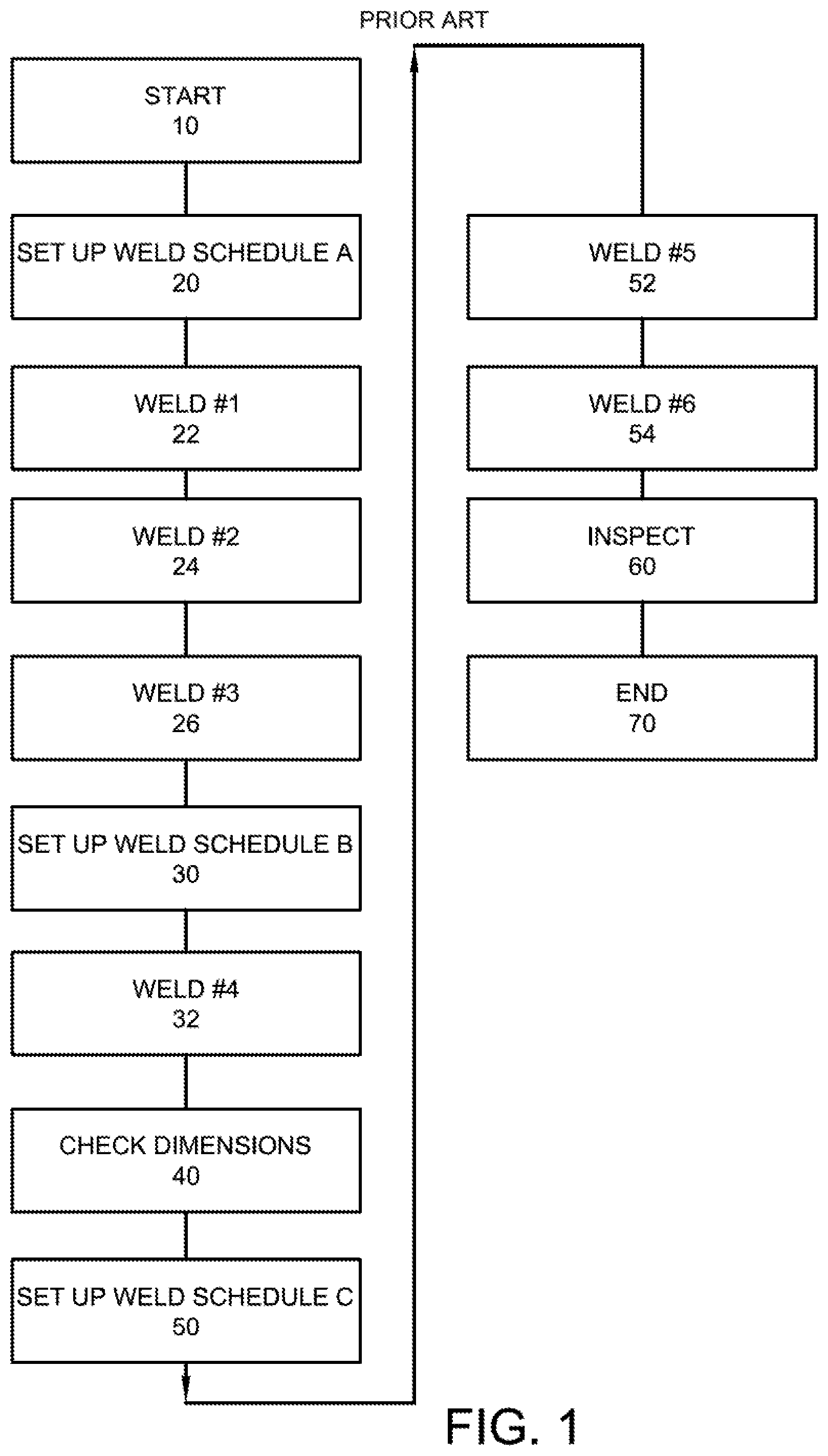
An illustrative example of the above problems is shown in the related art semi-automatic welding method diagrammatically represented in FIG. 1. In this method, each of the various scheduling, sequencing, inspection and welding operations are organized and performed by the operator (i.e., the welder) himself. Specifically, the operator begins the welding job at operation 10. Then, the operator sets up the welding equipment according to schedule A, at operation 20. Next, the operator performs weld #1, weld #2, and weld #3 using welding schedule A at operations 22, 24 and 26. Then, the operator stops welding operations and sets up the welding equipment according to schedule B at operation 30. Next, the operator performs weld #4 using welding schedule B at operation 32. Then, the operator checks the dimensions of the assembly at operation 40, and sets up the welding equipment according to schedule C at operation 50. Next, the operator performs weld #5 and weld #6 using welding schedule C at operations 52 and 54. After the welding operations are completed, the operator visually inspects the welded assembly at operation 60, and completes the welding job at operation 70.
Clearly, the method shown in FIG. 1 depends on the operator to correctly follow the predefined sequencing for performing welds and inspections, to accurately change between welding schedules (such as at operation 30), and to perform the welding itself. Errors in any of these responsibilities can result either in rework (if the errors are caught during inspection at operation 60) or a defective part being supplied to the end user. Further, this exemplary semi-automatic welding method hampers productivity, because the operator must spend time configuring and reconfiguring weld schedules.
The above problems demand an improvement in the related art system.
SUMMARY OF THE INVENTION
In accordance with an embodiment of the present invention, a welding system is provided that includes a first component that is configured to receive a parameter related to a welding schedule, wherein the parameter is collected from data representative of a portion of a welding process; a second component that is configured to create a welding sequence for a welding work cell, wherein the welding sequence defines at least the parameter and the welding schedule for a first welding procedure to create a first weld on a workpiece and a second welding procedure to create a second weld on the workpiece; and a welding job sequencer component that is configured to employ the welding sequence for the welding work cell.
In accordance with an embodiment of the present invention, a method of welding in a welding work cell is provided that includes at least the steps of: collecting data representative of a portion of a welding process; identifying a first parameter related to a first welding schedule based on the collected data; identifying a second parameter related to a second welding schedule based on at least one of the collected data or a real time weld procedure; creating a welding sequence based on the first parameter and the second parameter, wherein the welding sequence defines a first welding procedure that includes the first parameter to create a first weld on a workpiece and a second welding procedure that includes the second parameter to create a second weld on the workpiece; storing the created welding sequence remote from the welding work cell; and utilizing the welding sequence to automatically modify a welding equipment within the welding work cell without intervention from an operator creating at least one of the first weld or the second weld.
In accordance with an embodiment of the present invention, a welding system is provided that includes at least the following: means for collecting a data file that includes a parameter with a welding schedule for a workpiece; means for creating a welding sequence for a welding work cell, wherein the welding sequence defines at least the parameter and the welding schedule for a first welding procedure to create a first weld on a workpiece and a second welding procedure to create a second weld on the workpiece; and means for employing the welding sequence for the welding work cell to perform one or more welds to assemble the workpiece by automatically adjusting a setting on a welding equipment within the welding work cell.
These and other objects of this invention will be evident when viewed in light of the drawings, detailed description and appended claims.
BRIEF DESCRIPTION OF THE DRAWINGS
The invention may take physical form in certain parts and arrangements of parts, a preferred embodiment of which will be described in detail in the specification and illustrated in the accompanying drawings which form a part hereof, and wherein:
FIG. 1 illustrates a welding operation of the related art utilizing a semi-automatic welding work cell;
FIG. 2 illustrates a welding operation according to the invention utilizing a semi-automatic welding work cell;
FIG. 3 is a block diagram illustrating a welding system that utilizes a welding job sequencer component to configure welding equipment for two or more weld operations to assembly a workpiece;
FIG. 4 is a block diagram illustrating a welding system that utilizes a welding job sequencer component;
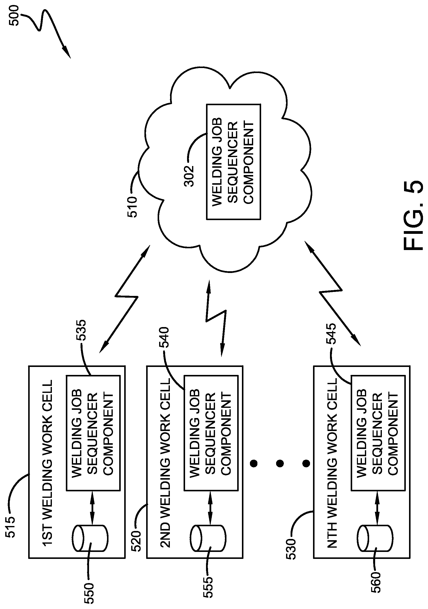
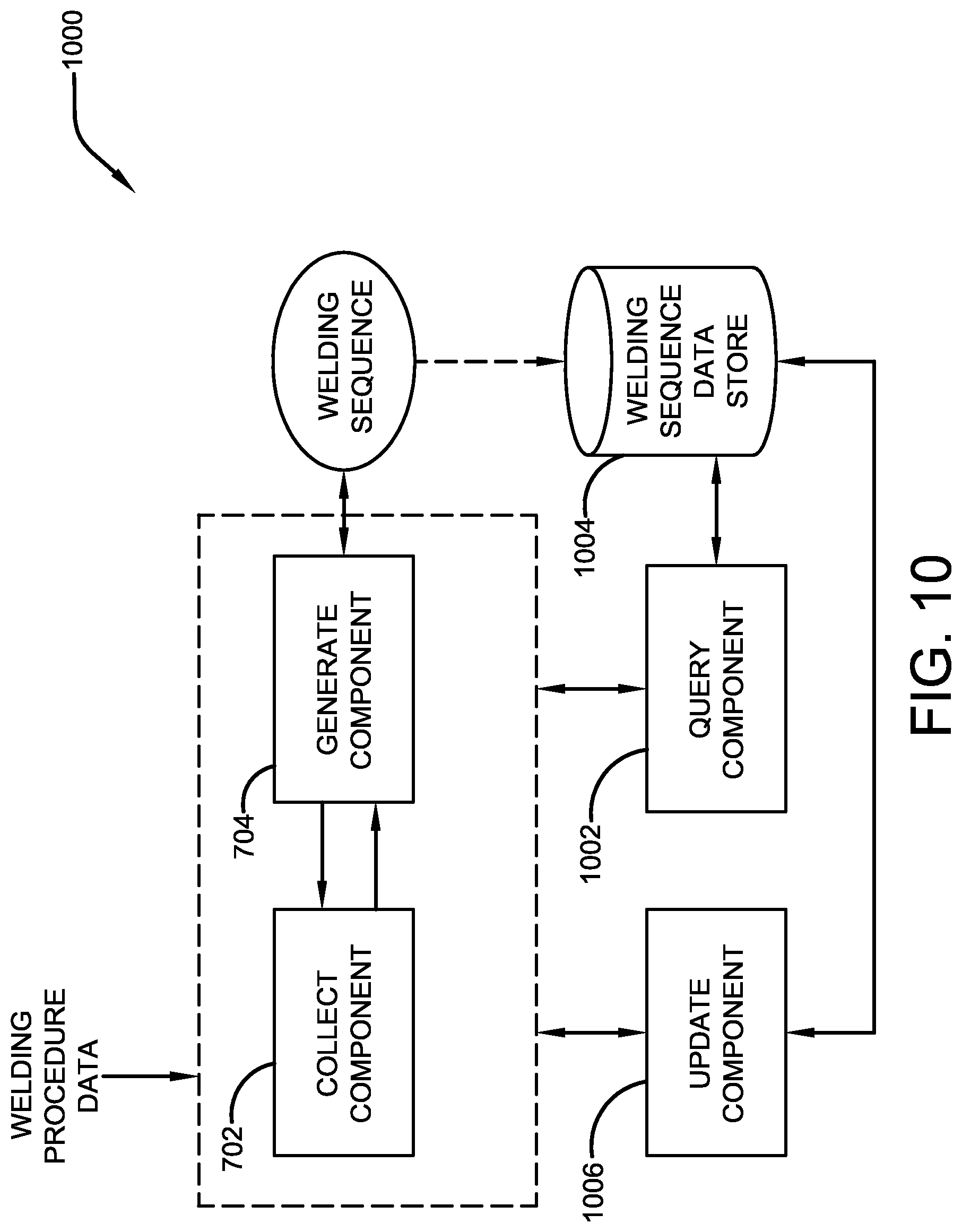
FIG. 5 is a block diagram illustrating a distributed welding environment with a plurality of welding work cells that interface with a welding job sequencer component via a local, remote, or cloud database;
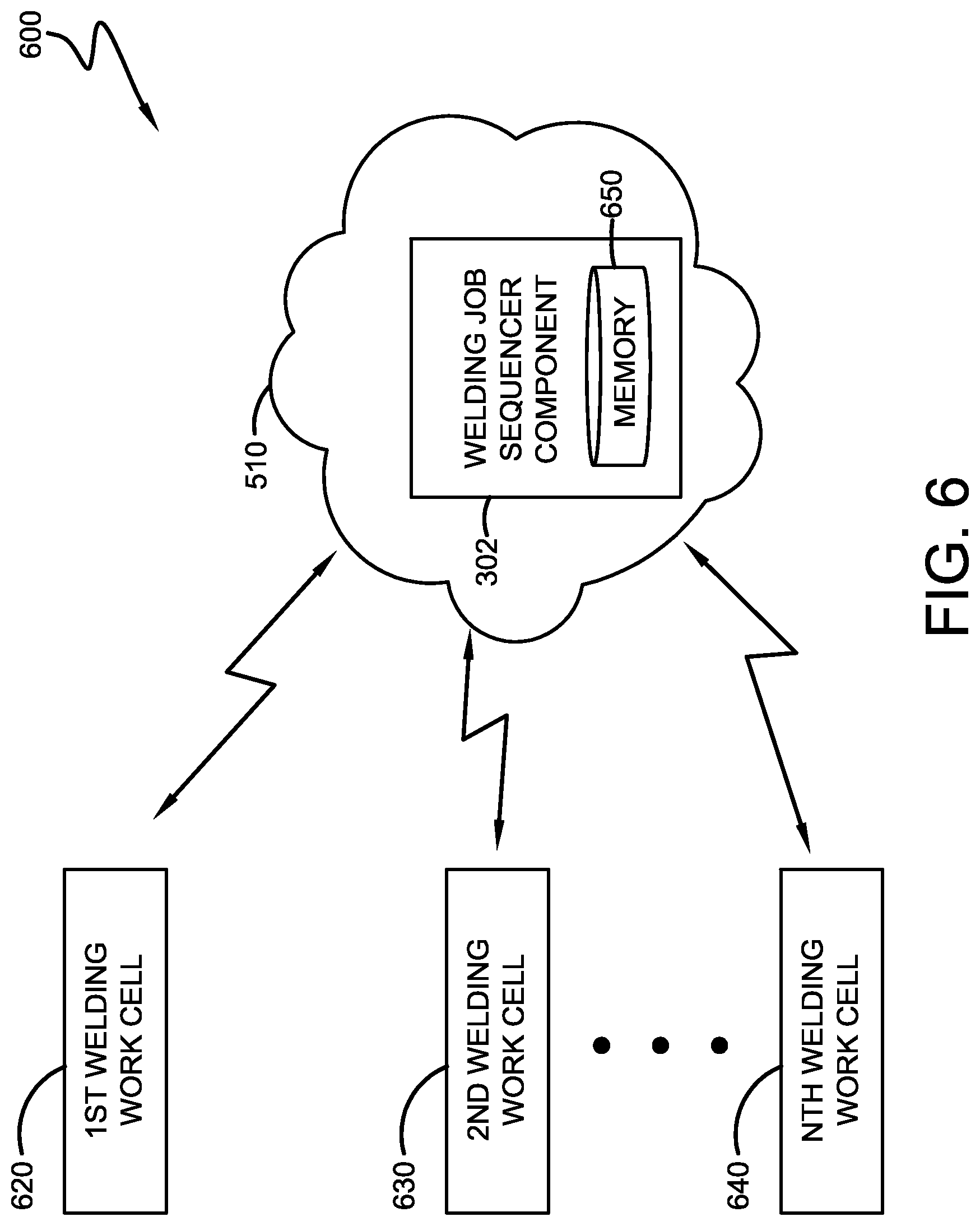
FIG. 6 is a block diagram illustrating a welding system that includes a plurality of welding work cells in which welding work cells are managed by a cloud-based welding job sequencer component;
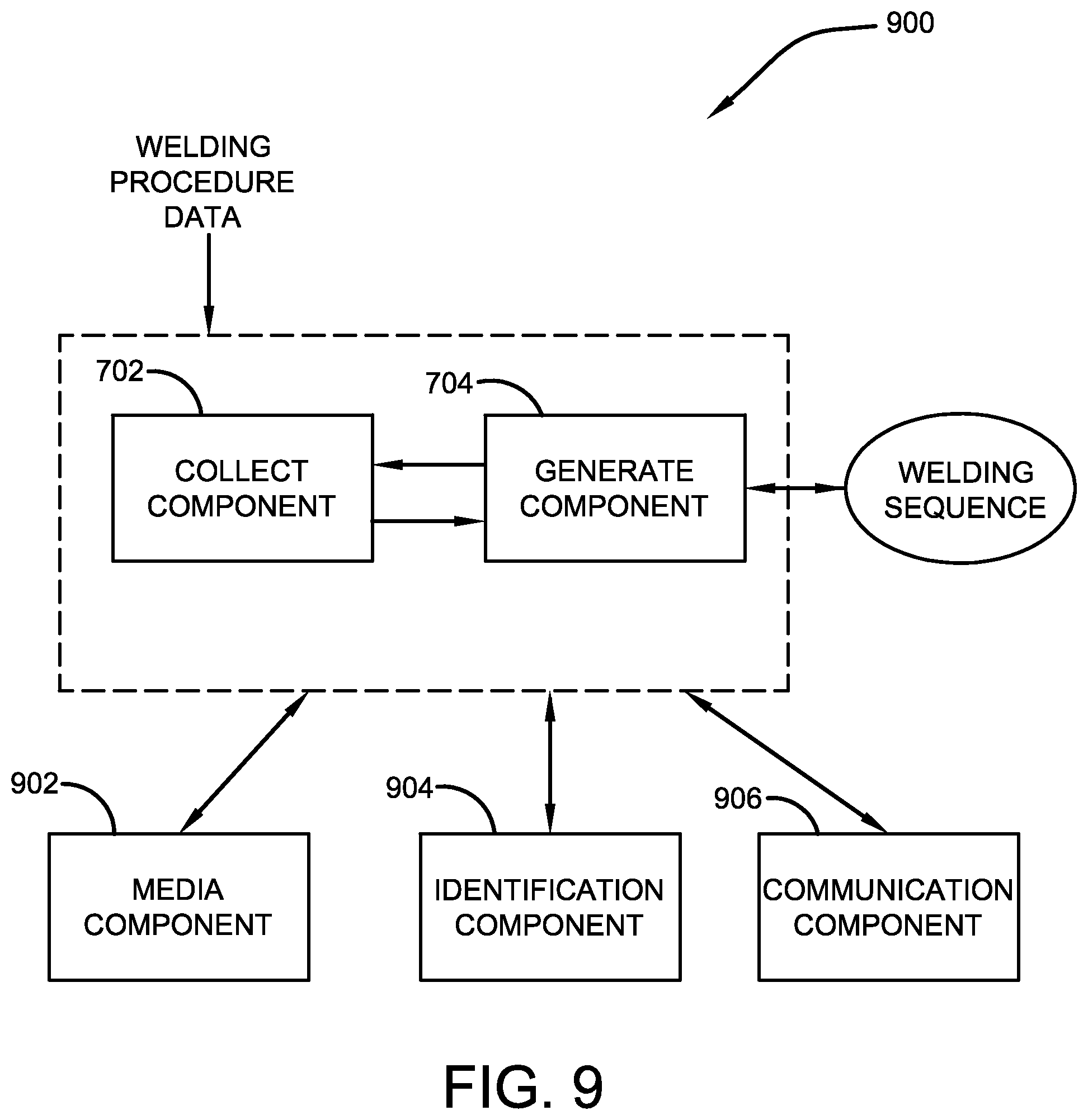
FIG. 7 is a block diagram illustrating a system that generates a welding sequence based on welding procedure data;
FIG. 8 is a block diagram illustrating a system that creates a welding sequence from a work instruction related to at least one of a workpiece or an assembly of a workpiece;
FIG. 9 is a block diagram illustrating a system that creates a welding sequence for employment in a welding environment;
FIG. 10 is a block diagram illustrating a system that utilizes a welding sequence for automatic configuration of a welding system to perform two or more welds;
FIG. 11 is a flow diagram of creating a welding sequence for employment to automatically configure welding equipment within a welding work cell; and
FIG. 12 is a flow diagram of creating a welding sequence based on one or more parameters of a welding procedure collected from a data file.
DETAILED DESCRIPTION OF THE INVENTION
Embodiments of the invention relate to methods and systems that relate to creating a welding sequence for a welding environment in which the welding sequence is based upon non-real time data collected from a welding procedure (e.g., data representative of a weld, among others). Welding procedure information is collected and utilized to create a welding sequence to perform two or more welds in which at least one parameter is based on the collected welding procedure information (e.g., non-real world welding procedure). The welding sequence is utilized to automatically configure a welding operation and/or at least one welding equipment to perform two or more welds that include disparate welding schedules (at least a portion of the welding schedules differ). Moreover, the welding sequence can eliminate operator intervention to configure or update welding equipment which allows the operator to concentrate on an act of welding rather than welding equipment settings, configurations, among others.
According to an aspect of the invention, there is provided a semi-automatic welding work cell including a welding job sequencer that automatically selects a welding schedule for use by an operator in the semi-automatic welding work cell.
According to another aspect of the invention, there is provided a method of welding in a semi-automatic work cell, including automatically selecting a welding schedule for use by an operator in the semi-automatic welding work cell.
According to another aspect of the invention, there is provided a welding production line including at least one semi-automatic welding work cell, where the semi-automatic work cell includes a welding job sequencer that automatically selects a welding schedule for use by an operator therein.
According to another aspect of the invention, there is provided a method of monitoring a welding production line, including automatically selecting a welding schedule for use by an operator in a semi-automatic welding work cell.
The term "component" as used herein can be defined as a portion of hardware, a portion of software, or a combination thereof. A portion of hardware can include at least a processor and a portion of memory, wherein the memory includes an instruction to execute.
The term "Welding Procedure Specification (WPS)" as used herein can be defined as information for specific application to assure repeatability by at least one of a welder or an operator.
The best mode for carrying out the invention will now be described for the purposes of illustrating the best mode known to the applicant at the time of the filing of this patent application. The examples and figures are illustrative only and not meant to limit the invention, which is measured by the scope and spirit of the claims. Referring now to the drawings, wherein the showings are for the purpose of illustrating an exemplary embodiment of the invention only and not for the purpose of limiting same, FIG. 2 is referenced. In an exemplary embodiment of the invention as illustrated in FIG. 2, a welding job sequencer is provided. The welding job sequencer improves the semi-automatic work cell of the related art by increasing the productivity of the semi-automatic work cell without compromising the number of weld schedules usable therein. The welding job sequencer accomplishes this improvement by implementing automatic changes in the semi-automatic work cell, and by providing the operator with an array of commands and instructions.
More specifically, in an exemplary embodiment, the welding job sequencer automatically selects and implements a function of the welding work cell. An example of such a function includes a particular weld schedule to be used with the semi-automatic work cell. In other words, the welding job sequencer may select a weld schedule to be used for a particular weld, and modify the settings of the semi-automatic work cell in accordance with the selected weld schedule, automatically for the operator (i.e., without the operator's specific intervention).
Additionally, in the exemplary embodiment, the welding job sequencer may automatically indicate a sequence of operations that the operator should follow to create a final welded assembly. In conjunction with the automatic selection of welding schedules, this indicated sequence allows an operator to follow the sequence to create a final welded part, without having to spend time adjusting, selecting, or reviewing each individual weld schedule and/or sequence.
Accordingly, since the welding job sequencer sets up the welding equipment and organizes the workflow, and since the operator only performs the welding operations themselves, the chance for error in the welding operation is greatly reduced, and productivity and quality are improved.
The exemplary embodiment is diagrammatically represented in FIG. 2. In FIG. 2, at operation 110, the welding job sequencer begins operation, and immediately sets the welding equipment to use weld schedule A (operation 120) and instructs the operator to perform welds #1, #2 and #3. Then, the operator performs welds #1, #2 and #3 using weld schedule A (operations 122, 124 and 126). Next, the welding job sequencer sets the welding equipment to use weld schedule B (operation 130), and instructs the operator to perform weld #4. Then the operator performs weld #4 using weld schedule B (operations 132). After completion of weld schedule B, the welding job sequencer sets the welding equipment to use weld schedule C (operation 150), and instructs the operator to perform welds #5 and #6, and to inspect the part. Then, the operator performs welds #5 and #6 (operations 152, and 154) using weld schedule C, and inspects the completed part to confirm that it is correct (operation 160). This inspection may include dimensional verification, visual defect confirmation, or any other type of check that might be needed. Further, operation 160 may include a requirement that the operator affirmatively indicate that the inspection is complete, such as by pressing an "OK" button, before it is possible to proceed to the next operation. Lastly, the welding job sequencer indicates that the welding operation is at an end (operation 170), and re-sets for the next operation.
Accordingly, as noted above, the sequencing and scheduling of welding operations is completed by the sequencer, and frees the operator to focus on performing welds according to instruction.
The welding job sequencer may select and implement a new function, such as the selection and implementation of weld schedules A, B and C shown in FIG. 2, based upon various variables or inputs. For example, the welding job sequencer may simply select new weld schedules based upon a monitoring of elapsed time since the beginning of the welding operations, or since the cessation of welding (such as the time after weld #3 in FIG. 2 above). Alternatively, the welding job sequencer may monitor the actions of the operator, compare the actions to the identified sequence of welds, and select new weld schedules appropriately. Still further, various combinations of these methods, or any other effective method, may be implemented, as long as the end effect is to provide an automatic selection and implementation of a function, such as the weld schedule, for use by the operator.
Parameters of the selected weld schedule may include such variables as welding process, wire type, wire size, WFS, volts, trim, which wire feeder to use, or which feed head to use, but are not limited thereto.
While the above description focuses on the selection of a weld schedule as a function which is automatically selected and implemented, the welding job sequencer is not limited to using only this function.
For example, another possible function that may be selected and implemented by the welding job sequencer is a selection of one of multiple wire feeders on a single power source in accordance with the weld schedule. This function provides an even greater variability in welding jobs capable of being performed by the operator in the semi-automatic work cell, since different wire feeders can provide a great variance of, for example, wire sizes and types.
Another example of a function compatible with the welding job sequencer is a Quality Check function. This function performs a quality check of the weld (either during welding or after the weld is completed) before allowing the job sequence to continue. The quality check can monitor various welding parameters and can pause the welding operation and alert the operator if an abnormality is detected. An example of a welding parameter measurable by this function would be arc data.
Another example of such a function would be a Repeat function. This function would instruct the operator to repeat a particular weld or weld sequence. An example of the use of this function includes when the Quality Check function shows an abnormality, or when multiple instances of the same weld are required.
Another example of such a function would be a Notify Welder function, which communicates information to the welder. This function would display information, give an audible signal, or communicate with the welder by some other means. Examples of use of this function include an indication to the operator that he is free to begin welding, or an indication that the operator should check some portion of the welded part for quality purposes.
Another example of such a function would be a Enter Job Information function. This function will require the welder to enter information, such as the part serial number, a personal ID number, or other special conditions before the job sequencer can continue. This information could also be read from a part or inventory tag itself through Radio Frequency Identification (RFID), bar code scanning, or the like. The welding job sequencer could then utilize the entered information for the welding operations. An example of the use of this function would be as a predicate to the entire welding operation, so as to indicate to the welding job sequencer which schedules and/or sequences should be selected.
A further example of such a function would be a Job Report function. This function will create a report on the welding job, which could include information such as: the number of welds performed, total and individual arc timing, sequence interruptions, errors, faults, wire usage, arc data, and the like. An example of the use of this function would be to report to a manufacturing quality department on the efficiency and quality of the welding processes.
A still further example of such a function would be a System Check function. This function will establish whether the welding job can continue, and could monitor such parameters as: wire supply, gas supply, time left in the shift (as compared to the required time to finish the job), and the like. The function could then determine whether the parameters indicate that there is enough time and/or material for the welding job to continue. This function would prevent down-time due to material depletion, and would prevent work-in-process assemblies from being delayed, which can lead to quality problems due to thermal and scheduling issues.
Further, as mentioned above, the welding job sequencer may select and implement a new function, based upon various variables or inputs. These variables and inputs are not particularly limited, and can even be another function. For example, another function compatible with the welding job sequencer is a Perform Welding Operation function. This function is designed to detect the actual welding performed by the operator, and to report that welding so that the welding job sequencer can determine whether to proceed with further operations. For example, this function can operate by starting when the operator pulls the trigger to start the welding operation, and finishing when the operator releases the trigger after the welding is complete, or after a predetermined period of time after it starts. This function could end when the trigger is released or it could be configured to automatically turn off after a period of time, a quantity of wire, or an amount of energy is delivered. This function may be used to determine when to select a new function, such as a new weld schedule, as discussed above.
Still further, various semi-automatic and/or robotic work cells can be integrated together on a single network, and the sequencing of welding steps at a single work-cell can be fully integrated into a complete production schedule, which itself can be modified as needed to track variations in the production schedule. Sequencing and/or scheduling information can also be stored in a database, be stored by date as archival information, and be accessed to provide various production reports
In an embodiment, a semi-automatic welding work cell for welding an assembly defined by a plurality of welds can be provided, the plurality of welds being defined by at least two weld schedules can include welding equipment for use by a welding operator to perform said plurality of welds and complete the assembly with said welding equipment having a plurality of functions. In the embodiment, the work cell can include a welding job sequencer that automatically selects a welding schedule for use by an operator in the semi-automatic welding work cell. In the embodiment, the welding job sequencer can select the welding schedule according to an elapsed time. In an embodiment, the welding job sequencer can detect when the operator is conducting a welding operation, and selects the welding schedule based upon that detection. In the embodiment, the welding job sequencer can detect when the operator is conducting a welding operation, and the welding job sequencer selects the welding schedule according to an amount of welding wire supplied for the welding operation. In the embodiment, the welding job sequencer can detect when the operator is conducting a welding operation, and the welding job sequencer selects the welding schedule according to an amount of energy supplied for the welding operation. In the embodiment, the welding schedule includes information about at least one of a welding process, wire type, wire size, WFS, volts, trim, wire feeder to use, or feed head to use.
In an embodiment, the welding work cell can include the welding job sequencer which select and implements at least one of a plurality of functions to define at least a first weld schedule and a second weld schedule from the at least two weld schedules so as to organize a workflow for creating the welded assembly and indicate to the welding operator a sequence of working operations for completing the assembly. In the embodiment, the welding job sequencer can automatically modify the welding equipment in accordance with the workflow and sequence of the welding operations without the welding operator intervening.
In the embodiment, the second weld schedule is defined according to an elapsed time of the first weld schedule. In the embodiment, the at least one function detects completion of said first weld schedule by said operator and automatically changes from said first weld schedule to said second weld schedule. In the embodiment, at least one function detects when the operator is conducting said first weld schedule, and said second weld schedule is defined according to an amount of welding wire supplied for said first weld schedule. In the embodiment, at least one function detects when the operator is conducting said first weld schedule, and said second weld schedule is defined according to an amount of energy supplied for said first weld schedule. In the embodiment, the at least one first weld set up parameter and said at least one second weld set up parameter comprise at least one of a welding process, wire type, wire size, WFS, volts, trim, wire feeder to use, or feed head to use. In the embodiment, at least one first weld set up parameter and said at least one second weld set up parameter comprise a feeder for use by an operator in the semi-automatic welding work cell. In the embodiment, at least one function monitors quality measurables of said weld assembly, wherein the quality measureables comprise at least information about an arc used to form the weld created by the operator In the embodiment, at least one function indicates information to the operator in the semiautomatic welding work cell. In the embodiment, at least one function accepts job information comprising at least a part ID number, operator ID number, or welding instructions. In the embodiment, at least one function produces a job report comprising at least one of a number of welds preformed, total arc time, individual arc time, sequence interruptions, errors, faults, wire usage, arc data. In the embodiment, at least one function includes a system check of said cell, the system check comprising at least a detection of wire supply, gas supply, and time.
In the embodiment, the welding job sequencer can select a welding sequence for use by the operator in the semi-automatic welding work cell. In the embodiment, the welding job sequencer can indicate the selected welding sequence to the operator in the semi-automatic welding work cell. In the embodiment, the welding job sequencer can select a wire feeder for use by an operator in the semi-automatic welding work cell. In the embodiment, the welding job sequencer can monitor quality measurables of a weld created by the operator, wherein the quality measureables comprise at least information about an arc used to form the weld created by the operator. In the embodiment, the welding job sequencer can indicate information to the operator in the semi-automatic welding work cell. In the embodiment, the welding job sequencer can accept job information comprising at least a part ID number, operator ID number, or welding instructions. In the embodiment, the welding job sequencer can produce a job report comprising at least one of a number of welds preformed, total arc time, individual arc time, sequence interruptions, errors, faults, wire usage, arc data. In the embodiment, the welding job sequencer can perform a system check comprising at least a detection of wire supply, gas supply, and time.
In an embodiment, a method of welding in a semi-automatic work cell can be provided that includes automatically selecting a welding schedule for use by an operator in the semi-automatic welding work cell. In the embodiment, the automatic selection can be performed after an elapsed time. In the embodiment, the method can include detecting when the operator is conducting a welding operation, wherein the automatic selection is performed based upon that detection. In the embodiment, the method can include detecting when the operator is conducting a welding operation, wherein the automatic selection is performed according to an amount of welding wire supplied for the welding operation. In the embodiment, the method can include detecting when the operator is conducting a welding operation, wherein the automatic selection is performed according to an amount of energy supplied for the welding operation. In the embodiment, the welding schedule can include information about at least one of a welding process, wire type, wire size, WFS, volts, trim, wire feeder to use, or feed head to use.
In the embodiment, the method can include selecting a welding sequence for use by the operator in the semi-automatic welding work cell. In the embodiment, the method can include indicating the selected welding sequence to the operator in the semi-automatic welding work cell. In the embodiment, the method can include selecting a wire feeder for use by an operator in the semi-automatic welding work cell. In the embodiment, the method can include monitoring quality measurables of a weld created by the operator, wherein the quality measureables comprise at least information about an arc used to form the weld created by the operator. In the embodiment, the method can include indicating information to the operator in the semi-automatic welding work cell. In the embodiment, the method can include accepting job information comprising at least a part ID number, operator ID number, or welding instructions. In the embodiment, the method can include producing a job report comprising at least one of a number of welds performed, total arc time, individual arc time, sequence interruptions, errors, faults, wire usage, arc data. In the embodiment, the method can include performing a system check comprising at least a detection of wire supply, gas supply, and time.
In an embodiment, a welding production line is provided with at least one semi-automatic welding work cell, wherein the semi-automatic work cell that includes a welding job sequencer that automatically selects a welding schedule for use by an operator therein. In the embodiment, the welding production line includes a monitoring system that communicates with the welding job sequencer to direct the welding job sequencer to automatically select the welding schedule for use by the operator therein.
In an embodiment, a method of monitoring a welding production line is provided that includes automatically selecting a welding schedule for use by an operator in a semi-automatic welding work cell. In the embodiment, the method can include directing the welding job sequencer to automatically select the welding schedule for use by the operator therein.
In an embodiment, a semi-automatic welding work cell is provided that includes a welding job sequencer that automatically selects a welding schedule for use by an operator in the semi-automatic welding work cell. The automatic selection may be by way of elapsed time, a detection of welding operations, a detection of the amount of welding wire supplied for the welding operation, or a detection of the amount of energy supplied for the welding operation.
In an embodiment, a method of welding in a semi-automatic work cell having welding equipment and a welding job sequencer to complete an assembly defined by a plurality of welds can be provided in which the plurality of welds can be defined by at least two weld schedules. The embodiment can include at least the steps of the following: implementing a welding equipment function with the welding job sequencer to define from the at least two weld schedules a first weld schedule having at least one first weld set up parameter and at least one first weld instruction and a second weld schedule having at least one second weld set up parameter and at least one second weld instruction, at least one of the said second weld set up parameter and said second weld instruction is different from said first weld set up parameter and said first weld instruction; indicating to a welding operator a sequence of welding operations for completing the assembly based on said first and second weld schedules; and automatically modifying said welding equipment in accordance with said sequence of welding operations for completing the assembly based on said first and second weld schedules.
In the embodiment, the method can include defining said second weld schedule is performed after an elapsed time defined by said first weld schedule. In the embodiment, the method can include detecting when the operator is conducting said first weld schedule, wherein defining said second schedule is based upon that detection. In the embodiment, defining said first and second weld schedules can include defining an amount of welding wire supplied for the welding operation. In the embodiment, defining said second weld schedule is according to an amount of energy supplied for the welding operation for said first weld schedule. In the embodiment, defining at least one of the first and second weld schedules can include selecting at least one of a welding process, wire type, wire size, WFS, volts, trim, wire feeder to use, or feed bead to use. In an embodiment, defining at least one of the first and second weld schedules can include selecting a wire feeder for use by an operator in the semi-automatic welding work cell. In an embodiment, the method can include monitoring quality measurables of a weld created by the operator, wherein the quality measureables comprise at least information about an arc used to form the weld created by the operator. In an embodiment, the method can include indicating information to the operator in the semi-automatic welding work cell. In an embodiment, the method can include accepting job information comprising at least a part ID number, operator ID number, or welding instructions. In an embodiment, the method can include producing a job report comprising at least one of a number of welds performed, total arc time, individual arc time, sequence interruptions, errors, faults, wire usage, arc data performing a system check comprising at least a detection of wire supply, gas supply, and time.
In an embodiment, a welding production line is provided that includes at least one semi-automatic welding work cell for welding an assembly defined by a plurality of welds, the plurality of welds being defined by at least weld schedules, the semi-automatic welding work cell including welding equipment for use by a welding operator to perform the plurality of welds and complete the assembly, the welding equipment having a plurality of functions. In the embodiment, the production line can include a welding job sequencer which selects and implements at least one of the plurality of functions to define at least a first and a second weld schedule in a sequence of welding operations from the at least two weld schedules to be used by said welding operator for completing the weld assembly. In an embodiment, the production line can include said first weld schedule contains at least one first weld set up parameter and at least one first weld instruction for said welding operator and said second weld schedule contains at least one second weld set up parameter and at least one second weld instruction for said welding operator, at least one of said first weld set up parameter and said first weld instruction is different from said second weld set up parameter and said second weld instruction, said welding job sequencer automatically modifying said welding equipment in accordance with said sequence of operations without said welding operator intervention. In an embodiment, the production line can include a monitoring system in communication with the welding job sequencer to monitor completion of the at least one weld instruction of each of the first and second weld schedule.
In an embodiment, a method for monitoring a welding production line in at least one semi-automatic welding work cell for use by a welding operator to complete an assembly defined by a plurality of welds, the plurality of welds being defined by at least two weld schedules, the semi-automatic welding work cell including welding equipment and a welding job sequencer. The method can include at least the following steps: defining at least a first and a second weld schedule in a sequence of welding operations from the at least two weld schedules with the welding job sequencer said first weld schedule having at least one first weld set up parameter and at least one first weld instruction and said second weld schedule defining at least one second weld set up parameter and at least one second weld instruction with at least one of said second weld set up parameter and said second weld instruction being different from said first weld set up parameter and said first weld instruction; determining completion of said first weld schedule by said welding operator; automatically modifying the welding equipment in accordance with said second weld schedule without said welding operator intervention; and monitoring the welding operations. In the embodiment, the method can include automatically modifying the welding equipment in accordance with said second weld schedule is based on said completion of said first weld schedule.
In an embodiment, a semi-automatic welding work cell for use by an operator is provided. The embodiment can include welding equipment having a plurality of functions for performing welds by the operator and a welding job sequencer selecting from the plurality of functions to set up and organize the welding equipment for the operator. The embodiment can include the plurality of functions including: a weld schedule function defined by a sequence of weld operations; a notify function to instruct the operator to perform the weld schedule; and a quality check function to monitor at least one weld operation of the sequence of weld operations.
In the embodiment, the quality check function performs a quality check on a weld completed by the at least one weld operation. In the embodiment, the quality check function monitors the at least one weld operation during the at least one weld operation. In the embodiment, the quality check function monitors the at least one weld operation after completion of the at least one weld operation. In the embodiment, the weld schedule function defines a plurality of weld schedules, each weld schedule having a first weld operation and at least a second weld operation. In the embodiment, the quality check function monitors the at least one weld operation before allowing the sequence of weld operations to continue. In the embodiment, the quality check function detects an abnormality, the sequencer pauses the sequence of weld operations and the notify function alerts the operator of the abnormality.
FIG. 3 is a schematic block diagram of an exemplary embodiment of welding system 300 that utilizes welding job sequencer component 302 to configure welding equipment for two or more weld operations to assembly a workpiece. Welding job sequencer component 302 is configured to implement a welding sequence that includes settings, configurations, and/or parameters to perform two or more welding procedures on a workpiece. In particular, welding job sequencer component 302, as discussed above as welding job sequencer, automatically configures welding equipment to create two or more welds that include two or more welding schedules. Moreover, welding job sequencer component 302 utilizes the welding sequence to aid an operator to perform the two or more welds. As discussed above, welding job sequencer component 302 can be utilized with welding work cell 304 that is semi-automatic. However, it is to be appreciated and understood that welding job sequencer component 302 can be implemented in a suitable welding environment or system that includes at least welding equipment and an operator to facilitate creating one or more welds.
Welding system 300 further includes check point component 306 that is configured to monitor a welding process and/or a welding operator in real time. For instance, the welding process is monitored in real time to detect at least one of a welding parameter (e.g., voltage, current, among others), a welding schedule parameter (e.g., welding process, wire type, wire size, WFS, volts, trim, wire feeder to use, feed head to use, among others), a weld on a workpiece as the weld is created, a movement of an operator, a position of a welding tool, a position or location of a welding equipment, a position or location of an operator, sensor data (e.g., video camera, image capture, thermal imaging device, heat sensing camera, temperature sensor, among others), and the like. Check point component 306 includes an alert system (not shown) that can communicate an alert or notification to indicate a status of the real time monitoring. In an embodiment, check point component 306 can utilize thresholds, ranges, limits, and the like for the real time monitoring to precisely identify a abnormality with welding system 300. Furthermore, check point component 306 can communicate an alert or notification to welding work cell 304 or the operator to at least one of stop the welding procedure, continue with the welding procedure, pause the welding procedure, terminate the welding procedure, or request approval of the welding procedure. In an embodiment, check point component 306 can store monitoring data (e.g., video, images, results, sensor data, and the like) in at least one of a server, a data store, a cloud, a combination thereof, among others.
Weld score component 308 is included with welding system 300 and is configured to evaluate a weld created by an operator within welding work cell 304 upon completion of such weld. Weld score component 308 provides a rating or score for the completed weld to facilitate implementing a quality control on the workpiece and/or assembly of the workpiece. For instance, weld score component 308 can alert a quality inspection upon completion, provide data collection of a job (e.g., assembly of workpiece, weld on workpiece, among others), and the like. In an embodiment, an in-person quality inspection can be performed upon completion of a portion of the assembly (e.g., completion of a weld, completion of two or more welds, completion of assembly, among others). In another embodiment, weld score component 308 can utilize a sensor to collect data (e.g., video camera, image capture, thermal imaging device, heat sensing camera, temperature sensor, among others) to determine approval of the job. For instance, a quality inspection can be performed remotely via video or image data collected upon completion of a job.
It is to be appreciated that welding job sequencer component 302 can be a stand-alone component (as depicted), incorporated into welding work cell 304, incorporated into check point component 306, incorporated into weld score component 308, or a suitable combination thereof. Additionally, as discussed below, welding job sequencer component 302 can be a distributed system, software-as-a-service (SaaS), a cloud-based system, or a combination thereof. Further, it is to be appreciated and understood that check point component 306 can be a stand-alone component (as depicted), incorporated into welding work cell 304, incorporated into welding job sequencer component 302, incorporated into weld score component 308, or a suitable combination thereof. Additionally, check point component 306 can be a distributed system, software-as-a-service (SaaS), a cloud-based system, or a combination thereof. Moreover, it is to be appreciated and understood that weld score component 308 can be a stand-alone component (as depicted), incorporated into welding work cell 304, incorporated into welding job sequencer component 302, incorporated into check point component 306, or a suitable combination thereof. Additionally, weld score component 308 can be a distributed system, software-as-a-service (SaaS), a cloud-based system, or a combination thereof.
FIG. 4 illustrates a schematic block diagram of an exemplary embodiment of welding system 400 including welding circuit path 405. It is to be appreciated that welding system 400 is also referred to as the welding work cell, wherein the welding work cell and/or welding system 400 can produce welds or welded parts. Welding system 400 includes welder power source 410 and display 415 operationally connected to welder power source 410. Alternatively, display 415 may be an integral part of welder power source 410. For instance, display 415 can be incorporated into welder power source 410, a stand-alone component (as depicted), or a combination thereof. Welding system 100 further includes welding cable 120, welding tool 430, workpiece connector 450, spool of wire 460, wire feeder 470, wire 480, and workpiece 440. Wire 480 is fed into welding tool 430 from spool 460 via wire feeder 470, in accordance with an embodiment of the present invention. In accordance with another embodiment of the present invention, welding system 400 does not include spool of wire 460, wire feeder 470, or wire 480 but, instead, includes a welding tool comprising a consumable electrode such as used in, for example, stick welding. In accordance with various embodiments of the present invention, welding tool 430 may include at least one of a welding torch, a welding gun, and a welding consumable.
Welding circuit path 405 runs from welder power source 410 through welding cable 420 to welding tool 430, through workpiece 440 and/or to workpiece connector 450, and back through welding cable 420 to welder power source 110. During operation, electrical current runs through welding circuit path 405 as a voltage is applied to welding circuit path 405. In accordance with an exemplary embodiment, welding cable 420 comprises a coaxial cable assembly. In accordance with another embodiment, welding cable 420 comprises a first cable length running from welder power source 410 to welding tool 430, and a second cable length running from workpiece connector 450 to welder power source 410.
Welding system 400 includes welding job sequencer component 302 (as described above). Welding job sequencer component 302 is configured to interact with a portion of welding system 400. For instance, welding job sequencer component 302 can interact with at least the power source 410, a portion of welding circuit path 405, spool of wire 460, wire feeder 470, or a combination thereof. Welding job sequencer component 302 automatically adjusts one or more elements of welding system 400 based on a welding sequence, wherein the welding sequence is utilized to configure welding system 400 (or an element thereof) without operator intervention in order to perform two or more welding procedures with respective settings or configurations for each welding procedure.
In an embodiment, welding job sequencer component 302 employs a welding sequence to automatically configure welding equipment. It is to be appreciated that welding system 400 or welding work cell can employ a plurality of welding sequences for assembly of one or more workpieces. For instance, a workpiece can include three (3) welds to complete assembly in which a first welding sequence can be used for the first weld, a second welding sequence can be used for the second weld, and a third welding sequence can be used for the third weld. Moreover, in such example, the entire assembly of the workpiece including the three (3) welds can be referenced as a welding sequence. In an embodiment, a welding sequence that includes specific configurations or steps can further be included within a disparate welding sequence (e.g., nested welding sequence). A nested welding sequence can be a welding sequence that includes a welding sequence as part of the procedure. Moreover, the welding sequence can include at least one of a parameter, a welding schedule, a portion of a welding schedule, a step-by-step instruction, a portion of media (e.g., images, video, text, and the like), a tutorial, among others. In general, the welding sequence can be created and employed in order to guide an operator through welding procedure(s) for specific workpieces without the operator manually setting welding equipment to perform such welding procedures. The subject innovation relates to creating a welding sequence and/or modifying a welding sequence.
One or more welder power source(s) (e.g., welder power source 410) aggregates data respective to a respective welding process to which the welder power source is providing power to implement. Such collected data relates to each welder power source and is herein referred to as "weld data." Weld data can include welding parameters and/or information specific to the particular welding process the welder power source is supplying power. For instance, weld data can be an output (e.g., a waveform, a signature, a voltage, a current, among others), a weld time, a power consumption, a welding parameter for a welding process, a welder power source output for the welding process, and the like. In an embodiment, weld data can be utilized with welding job sequencer component 302. For example, weld data can be set by a welding sequence. In another example, weld data can be used as a feedback or a feedforward loop to verify settings.
In one embodiment, welding job sequencer component 302 is a computer operable to execute the disclosed methodologies and processes, including methods 1100 and 1200 described herein. In order to provide additional context for various aspects of the present invention, the following discussion is intended to provide a brief, general description of a suitable computing environment in which the various aspects of the present invention may be implemented. While the invention has been described above in the general context of computer-executable instructions that may run on one or more computers, those skilled in the art will recognize that the invention also may be implemented in combination with other program modules and/or as a combination of hardware and/or software. Generally, program modules include routines, programs, components, data structures, etc., that perform particular tasks or implement particular abstract data types.
Moreover, those skilled in the art will appreciate that the inventive methods may be practiced with other computer system configurations, including single-processor or multiprocessor computer systems, minicomputers, mainframe computers, as well as personal computers, hand-held computing devices, microprocessor-based or programmable consumer electronics, and the like, each of which may be operatively coupled to one or more associated devices. The illustrated aspects of the invention may also be practiced in distributed computing environments where certain tasks are performed by remote processing devices that are linked through a communications network. In a distributed computing environment, program modules may be located in both local and remote memory storage devices. For instance, a remote database, a local database, a cloud-computing platform, a cloud database, or a combination thereof can be utilized with welding job sequencer 302.
Welding job sequencer 302 can utilize an exemplary environment for implementing various aspects of the invention including a computer, wherein the computer includes a processing unit, a system memory and a system bus. The system bus couples system components including, but not limited to the system memory to the processing unit. The processing unit may be any of various commercially available processors. Dual microprocessors and other multi-processor architectures also can be employed as the processing unit.
The system bus can be any of several types of bus structure including a memory bus or memory controller, a peripheral bus and a local bus using any of a variety of commercially available bus architectures. The system memory can include read only memory (ROM) and random access memory (RAM). A basic input/output system (BIOS), containing the basic routines that help to transfer information between elements within welding job sequencer 302, such as during start-up, is stored in the ROM.
Welding job sequencer 302 can further include a hard disk drive, a magnetic disk drive, e.g., to read from or write to a removable disk, and an optical disk drive, e.g., for reading a CD-ROM disk or to read from or write to other optical media. Welding job sequencer 302 can include at least some form of computer readable media. Computer readable media can be any available media that can be accessed by the computer. By way of example, and not limitation, computer readable media may comprise computer storage media and communication media. Computer storage media includes volatile and nonvolatile, removable and non-removable media implemented in any method or technology for storage of information such as computer readable instructions, data structures, program modules or other data. Computer storage media includes, but is not limited to, RAM, ROM, EEPROM, flash memory or other memory technology, CD-ROM, digital versatile disks (DVD) or other magnetic storage devices, or any other medium which can be used to store the desired information and which can be accessed by welding job sequencer 302.
Communication media typically embodies computer readable instructions, data structures, program modules or other data in a modulated data signal such as a carrier wave or other transport mechanism and includes any information delivery media. The term "modulated data signal" means a signal that has one or more of its characteristics set or changed in such a manner as to encode information in the signal. By way of example, and not limitation, communication media includes wired media such as a wired network or direct-wired connection, and wireless media such as acoustic, Radio Frequency (RF), Near Field Communications (NFC), Radio Frequency Identification (RFID), infrared, and/or other wireless media. Combinations of any of the above should also be included within the scope of computer readable media.
A number of program modules may be stored in the drives and RAM, including an operating system, one or more application programs, other program modules, and program data. The operating system in welding job sequencer 302 can be any of a number of commercially available operating systems.
In addition, a user may enter commands and information into the computer through a keyboard and a pointing device, such as a mouse. Other input devices may include a microphone, an IR remote control, a track ball, a pen input device, a joystick, a game pad, a digitizing tablet, a satellite dish, a scanner, or the like. These and other input devices are often connected to the processing unit through a serial port interface that is coupled to the system bus, but may be connected by other interfaces, such as a parallel port, a game port, a universal serial bus ("USB"), an IR interface, and/or various wireless technologies. A monitor (e.g., display 415), or other type of display device, may also be connected to the system bus via an interface, such as a video adapter. Visual output may also be accomplished through a remote display network protocol such as Remote Desktop Protocol, VNC, X-Window System, etc. In addition to visual output, a computer typically includes other peripheral output devices, such as speakers, printers, etc.
A display (in addition or in combination with display 415) can be employed with welding job sequencer 302 to present data that is electronically received from the processing unit. For example, the display can be an LCD, plasma, CRT, etc. monitor that presents data electronically. Alternatively or in addition, the display can present received data in a hard copy format such as a printer, facsimile, plotter etc. The display can present data in any color and can receive data from welding job sequencer 302 via any wireless or hard wire protocol and/or standard. In another example, welding job sequencer 302 and/or system 400 can be utilized with a mobile device such as a cellular phone, a smart phone, a tablet, a portable gaming device, a portable Internet browsing device, a Wi-Fi device, a Portable Digital Assistant (PDA), among others.
The computer can operate in a networked environment using logical and/or physical connections to one or more remote computers, such as a remote computer(s). The remote computer(s) can be a workstation, a server computer, a router, a personal computer, microprocessor based entertainment appliance, a peer device or other common network node, and typically includes many or all of the elements described relative to the computer. The logical connections depicted include a local area network (LAN) and a wide area network (WAN). Such networking environments are commonplace in offices, enterprise-wide computer networks, intranets and the Internet.
When used in a LAN networking environment, the computer is connected to the local network through a network interface or adapter. When used in a WAN networking environment, the computer typically includes a modem, or is connected to a communications server on the LAN, or has other means for establishing communications over the WAN, such as the Internet. In a networked environment, program modules depicted relative to the computer, or portions thereof, may be stored in the remote memory storage device. It will be appreciated that network connections described herein are exemplary and other means of establishing a communications link between the computers may be used.
Alternatively or in addition, a local or cloud (e.g., local, cloud, remote, among others) computing platform can be utilized for data aggregation, processing, and delivery. For this purpose, the cloud computing platform can include a plurality of processors, memory, and servers in a particular remote location. Under a software-as-a-service (SaaS) paradigm, a single application is employed by a plurality of users to access data resident in the cloud. In this manner, processing requirements at a local level are mitigated as data processing is generally done in the cloud, thereby relieving user network resources. The software-as-a-service application allows users to log into a web-based service (e.g., via a web browser) which hosts all the programs resident in the cloud.
Turning to FIG. 5, system 500 illustrates a welding environment with a plurality of welding work cells via a local, remote, or cloud database. System 500 includes a plurality of welding work cells such as first welding work cell 515, second welding work cell 520 to Nth welding work cell 530, where N is a positive integer. In an embodiment, each welding work cell includes a welding job sequencer component 535, 540, and 545, that is used to implement a welding schedule(s) to each welding work cell as well as or in the alternative to an enterprise-wide welding operation(s) and/or enterprise-wide welding work cell. Welding sequence(s) from each welding job sequencer component 535, 540, and 545 is received from the local or cloud database (e.g., local database, cloud database, remote database, among others) computing platform 510.
In an embodiment, each welding work cell further includes a local data store. For instance, first welding work cell 515 includes welding job sequencer component 535 and data store 550, second welding work cell 520 includes welding job sequencer component 540 and data store 555, and Nth welding work cell 530 includes welding job sequencer component 545 and data store 560. It is to be appreciated that system 500 includes welding job sequencer 302 hosted by computing platform 510 in which each welding work cell includes a distributed and respective welding job sequencer component. Yet, it is to be understood that welding job sequencer 302 (and distributed welding job sequencer components 535, 540, and 545) can be a stand-alone component in each welding work cell or a stand-alone component in the computing platform 510.
Each welding work cell can include a respective data store that stores a portion of at least one welding sequence. For instance, welding sequences related to a welding process A is employed at one or more welding work cell. The welding sequence is stored in a respective local data store (e.g., data stores 550, 555, and 560). Yet, it is to be appreciated and understood that each welding work cell can include a local data store (as depicted), a collective and shared remote data store, a collective and shared local data store, a cloud data store hosted by computing platform 510, or a combination thereof. A "data store" or "memory" can be, for example, either volatile memory or nonvolatile memory, or can include both volatile and nonvolatile memory. The data store of the subject systems and methods is intended to comprise, without being limited to, these and other suitable types of memory. In addition, the data store can be a server, a database, a hard drive, a flash drive, an external hard drive, a portable hard drive, a cloud-based storage, and the like.
For instance, welding job sequencer component 302 can manage each welding job sequencer component 535, 540, 545 in each welding work cell 515, 520, 530. In another embodiment, the communications can be transmitted from welding job sequencer 302 to each welding work cell (e.g., each welding job sequencer component). In another embodiment, the communications can be received from each welding work cell (e.g., each welding job sequencer component) from the welding job sequencer component 302. For instance, a welding sequence can be used with 1.sup.st welding work cell 515 and communicated directly to a disparate welding work cell or via computing platform 510.
FIG. 6 illustrates welding system 600 that includes a plurality of welding work cells in which welding job sequencer component 302 is hosted with computing platform 510 to utilize one or more welding sequences to configure welding equipment within one or more welding systems, welding environments, and/or welding work cells. Welding system 600 includes a local or cloud-based welding job sequencer component 302 hosted in computing platform 510. Welding job sequencer component 302 can utilize a welding sequence with a number of welding work cell. For instance, welding system 600 can a number of welding work cells such as, but not limited to, 1.sup.st welding work cell 620, 2.sup.nd welding work cell 630, to Nth welding work cell, where N is a positive integer. It is to be appreciated that the locality of the welding job sequencer component 302 is in relation to each 1.sup.st welding work cell 620, 2.sup.nd welding work cell 630, and/or Nth welding work cell 640.
In an embodiment, welding job sequencer 302 communicates one or more welding sequence to a target welding work cell, wherein the target welding work cell is a welding work cell that is to utilize the communicated welding sequence. Yet, in another embodiment, welding job sequencer 302 utilizes memory 650 hosted by computing platform 510 in which one or more welding sequences are stored. Yet, the stored welding sequence can be related or targeted to one or more welding work cells regardless of a storage location (e.g., local, cloud, remote, among others).
FIG. 7 illustrates system 700 that generates a welding sequence based on welding procedure data. System 700 includes collect component 702 that is configured to receive a portion of welding procedure data to create welding sequence 706. Collect component 702 receives, collects, aggregates, and/or identifies a portion of welding procedure data in which generate component 704 utilizes to create welding sequence 706. As discussed above, welding sequence 706 is used by a welding job sequencer component (See FIGS. 3-6) to perform two or more welds with two or more respective welding parameters (e.g., welding schedules, parameters, configurations, settings, and the like). In particular, welding sequence 706 is employed to automatically configure welding equipment without operator intervention to perform a first welding operation with a first welding schedule and a second welding operation with a second welding schedule.
The portion of welding procedure data is data representative of a weld in a non-real world environment. For instance, a portion of welding procedure data is data based upon a non-real world welding operation (e.g., computer-based replication or representation of a weld, data, among others). By way of example and not limitation, welding procedure data can be at least one of a data file (e.g., text file, word processing document file, spreadsheet data file, email, text message, computer-aided design (CAD) file, image file, 3-dimensional (3D) data file, work instructions, Welding Procedure Specification (WPS), among others), wherein the data file can include welding parameters, settings (e.g., voltage, current, and the like), welding type, weld size, weld dimensions (e.g., length, width, height, among others), material for workpiece, among others. From the data file or welding procedure data, system 700 can aggregate and identify other welding parameters used with the weld or welding procedure such as, but not limited to, welding equipment configurations (e.g., power source settings, waveforms, wire feed speed, and the like), welder setup (e.g., workpiece type, wire type, material type, weld to perform, and the like), among others. In another embodiment, a welding sequence and/or a welding sequence step can be created from a work instruction, work order, order request, purchase order, among others.
In an embodiment, a group of steps for welding sequence 706 can be inserted with a data file. For instance, a welding sequence with ten (10) welding operations can be added with a data file that includes welding procedure data for each step. By way of example and not limitation, welding procedure data and/or a data file can be utilized as a source code and/or with a compiler (not shown) to generate welding sequence 706 based on data contained therein. For instance, commands, operators, operators, expressions, inputs, and the like can be included within the data file and/or welding procedure data and be further employed to create (e.g., compiled) welding sequence.
In an embodiment, a CAD model can be utilized as a data file and/or welding procedure data to generate welding sequence 706. By way of example and not limitation, the CAD model can be used to import weld sequence(s). Thus, a hypothetical weld, created in with CAD or other computer-generated imagery, can be utilized as a foundation for a weld sequence to create real world weld(s). In another example, a 3D model that is printed or created from 3D printing can be utilized as a data file or data representative of a weld. 3D printing can be a process of making a three-dimensional solid object of virtually any shape from a digital model, wherein the 3D printing is achieved using an additive process with successive layers of material being laid down in different shapes.
As discussed above, system 700 creates welding sequence 706 based on welding procedure data or data file(s) to train a welding job sequencer component, wherein the welding job sequencer component utilizes the created welding sequence 706 to perform two or more welds. In an embodiment, welding procedure data is a data file representative of a weld such as, for instance, a CAD file, CAD model, CAD drawing, among others. Welding sequence 706 can be generated based on such data file(s). In another embodiment, such data file(s) can be used for revision control or changes to be made for welding sequence 706. In still another embodiment, WPS information can be utilized alone or in combination with the data file(s).
Although system 700 is illustrated as a stand-alone system, it is to be appreciated that system 700 can be a stand-alone system (as depicted), incorporated into welding job sequencer component (not shown), or a combination thereof. Further, welding procedure data can be received via welding job sequencer and thus from a local data store, a remote data store, a cloud-based data store, a computing platform, and/or any other network or computing environment configuration discussed above in regards to the welding job sequencer. For instance, a welding environment A can collect welding procedure data or parameters in which such welding procedure data is communicated (e.g., via Internet, cloud, computing platform, among others) to welding environment B. Welding environment B can utilize the welding procedure data from environment A to create a welding sequence for welding environment B based on a correlation or matched parameter for the welding procedure to perform.
In an embodiment, non-real world weld data can be utilized by generate component 704 to create welding sequence 706 independent of a welding environment to which welding procedure data originates. For instance, welding procedure data can be collected from data representative (e.g., data file) of a weld, wherein additional welding data parameters can be determined related to, for instance, welding equipment, welding environments, welding work cells, and the like. Based on data file(s), generate component 704 can further be configured to identify one or more parameters to use as welding sequence 706. In an embodiment, a computer-based evaluation can be utilized to determine additional welding parameters or settings for a welding sequence based on the data file utilized by generate component 704. In another embodiment, an operator or user can create data file(s) to use as a basis for welding sequence 706, wherein the welding sequence can be automatically supplemented with settings or configurations based upon the created data file(s). As discussed above, a cloud-based platform or computing platform can be employed to utilize welding procedure data used to generate welding sequence(s) 706.
In an example, a welding sequence can include a replenishment of a consumable. The welding sequence can be created or edited to include a replenishment of a consumable for at least one of a welding work cell, a welding equipment, among others. For instance, a replenishment of a consumable can be included with a welding sequence after a period of time, wherein the period of time is estimated based on the duration the welding equipment is used (e.g., estimate the use of consumables). Thus, a welding environment, welding system, and/or welding work cell can be evaluated in real time or from collected real time data and identify data to determine a replenishment of a consumable.
In an embodiment, welding sequence can be compiled or created to include a replenishment of a consumable during downtime (e.g., shift change, duration of time welding equipment is not used, among others). In particular, a gas mixture changeover can be programmed within welding sequence 706. In another example, a gas mixture changeover can be performed during downtime between sequence steps and/or between one welding sequence and another welding sequence. By way of example and not limitation, a functional block for gas solenoid selection can be utilized for each pass.
In another example, a welding sequence can include an inspection or a repair. The welding sequence can be created or edited to include an inspection request or a repair request based on a factor such as, but not limited to, a time, a duration, among others. A welding work cell can have a maintenance period for a particular time and if a welding sequence is created for such welding work cell, a repair or maintenance can be included with the created welding sequence. Thus, a welding environment, welding system, and/or welding work cell can be evaluated in real time or from collected real time data and identify data to determine inspections or repairs.
Furthermore, it is to be appreciated and understood that collect component 702 can be a stand-alone component (as depicted), incorporated into generate component 704, incorporated into the welding job sequencer component (not shown), or a combination thereof. Additionally, generate component 704 can be a stand-alone component (as depicted), incorporated into collect component 704, incorporated into the welding job sequencer component (not shown), or a combination thereof.
FIG. 8 illustrates system 800 that creates a welding sequence from a work instruction related to at least one of a workpiece or an assembly of a workpiece. System 800 further includes work instructions 802 related to at least one of workpiece 808 or the assembly of workpiece 808 utilizing welding equipment 806. It is to be appreciated and understood that work instructions 802 are used solely for example and any suitable welding procedure data as discussed above can be utilized. Work instructions can be created or identified by at least one of a user, a computer-based system, or a combination thereof. For instance, a first system can be used by a user to create a data file representative of a weld (e.g., work instruction) and a second system can be used by a second user to identify or create a welding sequence based on such data file. In another embodiment, operator 804 can input work instructions received from a client, wherein a welding sequence can be generated therefrom. By way of example and not limitation, welding sequence based upon work instructions 802 allow operator 804 to perform a weld (e.g., create the weld with welding equipment 806 on workpiece 808).
In another embodiment, data file(s) or data representative of a weld (e.g., work instructions 802, among others) can be stored in a data store (discussed in more detail below). With a data store, characteristics (e.g., weld type, material, workpiece, type of welding equipment, wire feed speed, wire gauge, time, pace, among others) can be identified from which individual characteristics can be aggregated to create one or more welding sequences. In other words, individual data (welding procedure data representative of a single weld) can be collected for a particular welding sequence (already created or being used) from which a best individual weld data tracked can replace existing data with the welding sequence (e.g., based upon performance analysis, among others).
FIG. 9 illustrates system 900 that creates a welding sequence for employment in a welding environment. System 900 includes media component 902 that is configured to include media to a welding sequence. It is to be appreciated that media can be, but is not limited to being, photos, images, graphics, text, audio, video, computer generated imagery, animations, dictations, voice recordings, and the like. For example, media component 902 includes media to facilitate performing a weld or welding operation from an operator perspective. In an embodiment, media component 902 includes a video of a weld being created for the welding sequence. Thus, when the welding sequence is used to create a weld, the video can guide an operator on how to perform the weld. In another example, media component 902 provides media related to at least one of safety concerns for utilizing the welding procedure, areas of caution, problematic situations, warnings, potential mistakes, scores, time, date, ranking of welding performed, among others. Media component 902 includes data with the welding sequence that can be displayed, communicated, or output to the operator, a location where the welding sequence is used, within a welding work cell, a welding environment, and the like. It is to be further appreciated that media component 902 is further configured to identify media from, for instance, welding procedure data, data representative of a weld, and/or a data file. For instance, media can be extracted from a work instruction, work order, purchase order, image data, among others. In still another embodiment, media related to a recorded virtual simulation of a weld can be included or associated with welding sequence(s) to facilitate performing a weld.
System 900 further includes identification component 904 that is configured to aggregate data for specification of the created welding sequence. Identification component 904 associates data to a welding sequence during or after creation, wherein the data can specify such welding sequence. By way of example and not limitation, the data can relate to date, time, user identification of who created, user identification of who modified, welding job, client, workpiece information, welding information (e.g., welding parameters, welding equipment settings, and the like), environment data (e.g., welding environment that welding sequence will be used, target welding equipment, and the like), job information (e.g., work order, client, work instructions, and the like), data file specifics, data file storage location, data file information (e.g., format, date created, time created, application to open the data file, and the like), among others. Identification component 904 is customizable to include data to locate and employ a welding sequence via search and/or query based on a criteria defined or included with a welding sequence. In an embodiment, a job-based criteria can be employed in which job related data is aggregated for a created welding sequence and associated therewith. Thus, after creation of the welding sequence, a query (discussed in more detail below) with job-based data can be utilized to locate and find the welding sequence. It is to be appreciated that various data can be collected and associated with a created welding sequence at various points of creation and that any suitable data can be collected at any suitable point during the creation of a welding sequence.
For instance, identification component 904 can collect an employee identification of a creator of a welding sequence. By way of example and not limitation, the employee identification can be related to a creator of the welding sequence, a creator of a data file used as part of a creation of a welding sequence, an editor of a welding sequence, among others. It is to be appreciated that identification component 904 can associate one or more employee identifications to a welding sequence to provide a tracking of each welding sequence creation, edit, and/or modification of a welding sequence. This employee identification information can be used to provide query results for one or more creators (e.g., employees, workers, users, and the like).
Moreover, it is to be appreciated and understood that identification component 904 can collect data for a portion of a welding sequence to enable portions or parts of a welding sequence to be identified or located. This, for instance, can allow a user to identify a part or portion of a welding sequence to reuse in a creation of another welding sequence.
System 900 further includes communication component 906 that is configured to transmit and/or receive at least a portion of a welding sequence. In an embodiment, communication component 906 can transmit a portion of a welding sequence from a first location to a second location. For example, a welding sequence can be communicated from a welding work cell to a disparate welding work cell, a welding environment to a disparate welding environment, an operator to a disparate operator, a combination thereof, among others. In an embodiment, communication component 906 is further configured to print data related to the welding sequence, wherein the data is at least one of work instructions, related media, client information, welding parameters, welding equipment settings, details of the welding sequence, among others. In an embodiment, communication component 906 is configured to print a work instruction from a welding sequence. In other words, the data file or welding procedure data (e.g., work instructions) utilized to create the welding sequence can be utilized to identify the work instructions from the welding sequence. In a particular example, communication component 906 can be configured to communicate a work instruction for a workpiece based on association with a welding sequence (e.g., wherein the work instruction is derived from the welding sequence) and the work instruction is physically coupled or connected to one or more workpieces or material used for assembly.
FIG. 10 illustrates system 1000 that utilizes a welding sequence for automatic configuration of a welding system to perform two or more welds. System 1000 includes query component 1002 that is configured to receive a query and provide a result based on the query. Query component 1002 can query one or more data stores discussed above. In particular, query component 1002 can query data stored with welding sequence data store 1004. Welding sequence data store 1004 stores at least one of a welding sequence, a portion of a welding sequence, and/or data (e.g., metadata, metadata tags, and the like) associated with a welding sequence. In an embodiment, data store 1004 stores data representative of a weld, data file(s), and/or welding procedure data. Query component 1002, based on a received query, can generate results from at least welding sequence data store 1004. Query component 1002 and welding sequence data store 1004 facilitate creating welding sequences (e.g., by allowing reuse of portions of a welding sequence, reuse data file(s), reuse data representative of a weld, and the like), management of welding sequences, and/or locating welding sequences (e.g., updating, synchronizing, consistency, and the like). As discussed above, query component 1002 can leverage data collected via identification component (See FIG. 9).
In an embodiment, welding procedure data and/or data file(s) can be identified by querying welding sequence data store 1004 and/or other data stores (discussed above). For instance, data file(s) or data representative of a weld can be evaluated by collect component 702 and/or generate component 704, wherein the evaluation allows identification of at least one portion of a welding sequence that matches or correlates to the data file(s) or data representation of a weld. In other words, data file(s) used to create a welding sequence can be supplemented with information from previously created welding sequences, real-world weld data collected in real time, other data files (e.g., other data files or data representative of a weld, other CAD files, other work instructions, and the like), among others. Thus, in a particular example, CAD data (e.g., a type of data representative of a weld) can be queried by query component 1002 to identify other CAD data that relates to the CAD data or real world weld data previously collected or utilized to create a welding sequence.
In an embodiment, query component 1002 is further configured to match a welding sequence based on a received query or data. For instance, a query requesting a welding sequence related to a particular data file(s) can be received by query component 1002 in which a welding sequence matching or including the particular data file is returned. In a more particular example, data representative of a weld (e.g., weld simulation program, 3D CAD model, CAD file, and the like) can be monitored and the query component 1002 can identify a welding sequence that matches or includes a portion of the data representative of the weld. Utilizing the matched welding sequence, welding equipment and/or operator(s) can be guided through the welding procedure. For instance, a CAD data file can be used as a basis to create a welding sequence which allows a physical weld to be created based on a virtual representation and/or data file representative of the weld.
System 1000 further includes update component 1006 that is configured to modify a previously created welding sequence. Update component 1006 modifies an existing welding sequence with new (e.g., non-existing data) or edited (e.g., previously existing data) information. It is to be appreciated that update component 1006 can create a new welding sequence that includes modified data and archive the previous welding sequence. In another embodiment, update component 1006 can replace the new welding sequence with modified data in place of the previous welding sequence. Moreover, it is to be appreciated that update component 1006 can be utilized with query component 1002, welding sequence data store 1004, and/or identification component (See FIG. 9).
For instance, a user can utilize query component 1002 to identify a previously created welding sequence in order to update the welding sequence with an updated media. Once identified via query component 1002 in welding sequence data store 1004 with identification component 904, the user or operator can add or replace media with the welding sequence to provide up-to-date specifications.
In an embodiment, upon completion of a created welding procedure, a data model and/or software model can be employed to manage factors of the welding procedure used for the welding procedure. The software model and/or data model evaluates welding procedures performed with a corresponding welding sequence from which factors can be adjusted. For instance, a cycle time and/or a progression for a welding procedure can be adjusted based upon at least one of a software model and/or a data model.
In view of the exemplary devices and elements described supra, methodologies that may be implemented in accordance with the disclosed subject matter will be better appreciated with reference to the flow charts and/or methodologies of FIGS. 11 and 12. The methodologies and/or flow diagrams are shown and described as a series of blocks, the claimed subject matter is not limited by the order of the blocks, as some blocks may occur in different orders and/or concurrently with other blocks from what is depicted and described herein. In an embodiment, a first input can be received prior to a second input (as described below). In another embodiment, a second input can be received prior to a first input. In an embodiment, the a first input and a second input can be received at substantially the same time. Moreover, not all illustrated blocks may be required to implement the methods and/or flow diagrams described hereinafter.
Sequentially, the following occurs as illustrated in the decision tree flow diagram 1100 of FIG. 11 which is a flow diagram 1100 that creates a welding sequence for employment to automatically configure welding equipment within a welding work cell. Methodology 1100 leverages data representative of a weld to create a welding sequence. Data representative of a portion of a welding process is collected (reference block 1102). A first parameter is identified in which the first parameter is related to a first welding schedule based on the collected data (reference block 1104). A second parameter is identified in which the second parameter is related to a second welding schedule based on at least one of the collected data or a real time weld procedure (reference block 1106). It is to be appreciated that the first parameter and/or the second parameter can be based upon at least one of data file(s) representative of a weld in which the data file(s) not captured from a real time welding procedure. For instance, the first parameter and/or the second parameter can be a CAD file, a work instruction, a 3-dimensional (3D) model, a work instruction, a work order, WPS data, computer generated image of a weld, among others. A welding sequence is created based on the first parameter and the second parameter, wherein the welding sequence defines a first welding procedure that includes the first parameter to create a first weld on a workpiece and a second welding procedure that includes the second parameter to create a second weld on the workpiece (reference block 1108). The created welding sequence is stored remote from the welding work cell (reference block 1110). For instance, the welding sequence is stored on a disparate network than a network that hosts a portion of the welding work cell. In another embodiment, the welding sequence can be stored locally in reference to the welding work cell (e.g., welding sequence stored on a same network as the welding work cell). The welding sequence is utilized to automatically modify a welding equipment within the welding work cell without intervention from an operator creating at least one of the first weld or the second weld (reference block 1112).
The following occurs as illustrated in the flow diagram 1200 of FIG. 12. Flow diagram 1200 relates to creating a welding sequence based on one or more parameters of a welding procedure collected from a data file. A data file is collected that includes a parameter with a welding schedule for a workpiece (reference block 1202). A welding sequence is created for a welding work cell, wherein the welding sequence defines at least the parameter and the welding schedule for a first welding procedure to create a first weld on a workpiece and a second welding procedure to create a second weld on the workpiece (reference block 1204). The welding sequence is employed for the welding work cell to perform one or more welds to assemble the workpiece by automatically adjusting a setting on a welding equipment within the welding work cell (reference block 1206).
By way of example and not limitation, welding equipment (e.g., controller for a welder power source, wire feeder, welder power source, among others) can include one or more steps related to a particular welding process for a specific workpiece, wherein a step can include a respective setting or configuration for at least one welding equipment. For instance, a first workpiece can include steps A, B, C, and D based on welding parameters desired, the welding process used, and/or the workpiece. In another example, a second workpiece can include steps B, C, A, E, and F. With the employment of a welding sequence, the controller implementing the steps for the welding process via the welder power source and/or welding equipment can be managed and/or instructed. For instance, the welding sequence can indicate at least one of the following: which steps to perform, redo a step, skip a step, pause a sequence of steps, among others. Furthermore, a controller (e.g., or other suitable component) can control one or more welder power sources, parameters, welding schedules, among others associated with one or more welding processes, wherein each welding process can have a corresponding welding sequence(s).
In an embodiment, a welder system is provided that includes a weld score component that is configured to evaluate at least one of the first weld or the second weld performed on the workpiece based upon at least one of an image of the first weld or the second weld or a user inspection. In an embodiment, a welder system is provided that includes a check point component that is configured to monitor the creation of at least one of the first weld or the second weld in real time. In an embodiment, a welder system is provided in which a welding job sequencer component instructs an operator of the welding work cell to assemble the workpiece with the first welding procedure and the second welding procedure having two separate welding schedules.
In an embodiment of a welder system, the data representative of the portion of the welding process is a computer-aided design (CAD) file. In an embodiment of a welder system, the data representative of the portion of the welding process is a work order instruction. In an embodiment of a welder system, the data representative of the portion of the welding process is a data file that includes information related to at least one of a welding equipment setting, a weld type, a material of the workpiece, or a customer for the workpiece. In an embodiment of a welder system, the data representative of the portion of the welding process is a welding procedure specification (WPS), wherein the WPS includes information for specific application to assure repeatability by at least one of a welder or an operator.
In an embodiment of a welder system, a second component (e.g., generate component) can utilize the welding sequence as a portion of an additional welding sequence. In an embodiment, a welder system can include a third component that is configured to create a work instruction based upon the welding sequence. In an embodiment, a welder system can include a data store that stores at least one of the parameter, the work schedule, or the welding sequence; and a fourth component that is configured to generate a query result based on a received query, wherein the query result is a welding sequence originating from a previously performed welding procedure from the data store that satisfies the received query.
In an embodiment, a welder system can include a fifth component that is configured to collect identification information for the welding sequence. In the embodiment, the identification information is metadata related to at least one of a user that created the welding sequence, a weld type, a client name, a material of the workpiece, a date, a time, a location, a serial number, a price, a wire speed, an originating welding procedure that is a source for the welding sequence, data location, data filename, data source, data file type, or a wire type.
In an embodiment, a method is provided that includes modifying the created welding sequence to update at least a portion of the first welding schedule or the second welding schedule based on data representative of the portion of the welding process. In an embodiment, a method is provided that includes modifying the created welding sequence with a portion of data related to a welding procedure performed in real time.
In an embodiment, the creating the welding process further includes evaluating at least one of the first parameter or the second parameter in comparison with a previously created welding sequence; identifying a correlation between the first parameter and the second parameter with a portion of at least one previously created welding sequence; and utilizing a portion of the previously created welding sequence to create the welding sequence. In an embodiment, a method is provided that includes appending the welding sequence with media to aid in performing at least one of the first weld or the second weld, the media is at least one of a video or an image.
The above examples are merely illustrative of several possible embodiments of various aspects of the present invention, wherein equivalent alterations and/or modifications will occur to others skilled in the art upon reading and understanding this specification and the annexed drawings. In particular regard to the various functions performed by the above described components (assemblies, devices, systems, circuits, and the like), the terms (including a reference to a "means") used to describe such components are intended to correspond, unless otherwise indicated, to any component, such as hardware, software, or combinations thereof, which performs the specified function of the described component (e.g., that is functionally equivalent), even though not structurally equivalent to the disclosed structure which performs the function in the illustrated implementations of the invention. In addition although a particular feature of the invention may have been disclosed with respect to only one of several implementations, such feature may be combined with one or more other features of the other implementations as may be desired and advantageous for any given or particular application. Also, to the extent that the terms "including", "includes", "having", "has", "with", or variants thereof are used in the detailed description and/or in the claims, such terms are intended to be inclusive in a manner similar to the term "comprising."
This written description uses examples to disclose the invention, including the best mode, and also to enable one of ordinary skill in the art to practice the invention, including making and using any devices or systems and performing any incorporated methods. The patentable scope of the invention is defined by the claims, and may include other examples that occur to those skilled in the art. Such other examples are intended to be within the scope of the claims if they have structural elements that are not different from the literal language of the claims, or if they include equivalent structural elements with insubstantial differences from the literal language of the claims.
The best mode for carrying out the invention has been described for purposes of illustrating the best mode known to the applicant at the time. The examples are illustrative only and not meant to limit the invention, as measured by the scope and merit of the claims. The invention has been described with reference to preferred and alternate embodiments. Obviously, modifications and alterations will occur to others upon the reading and understanding of the specification. It is intended to include all such modifications and alterations insofar as they come within the scope of the appended claims or the equivalents thereof.
* * * * *
References
-
en.wikipedia/microcontroller--downloadedFeb
-
dialogweb.com/cgi/dwclient?reg=1331233430487
-
engadget.com/2012/06/27/googles-project-glass-gets-some-more-details
-
lincolnelectric.com/assets/en_US/products/literature/s232.pdf
-
-
vizitechusa.com
-
simwelder.com
-
en.onew1ech.com/_d276479751.htm
-
ieeexplore.ieee.org/stamp/stamp.jsp?tp=&arnumber=5460347&tag=1
-
123arc.com
-
mdpi.com/journal/sensors
-
web.mst.eduHsai/publications/HU-IJHMT-2007-1-60.pdf
D00000
D00001
D00002
D00003
D00004
D00005
D00006
D00007
D00008
D00009
D00010
D00011
D00012
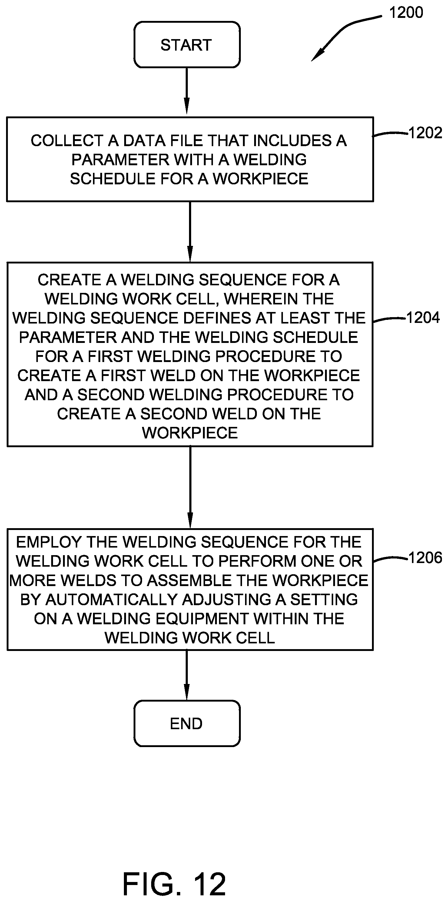
XML
uspto.report is an independent third-party trademark research tool that is not affiliated, endorsed, or sponsored by the United States Patent and Trademark Office (USPTO) or any other governmental organization. The information provided by uspto.report is based on publicly available data at the time of writing and is intended for informational purposes only.
While we strive to provide accurate and up-to-date information, we do not guarantee the accuracy, completeness, reliability, or suitability of the information displayed on this site. The use of this site is at your own risk. Any reliance you place on such information is therefore strictly at your own risk.
All official trademark data, including owner information, should be verified by visiting the official USPTO website at www.uspto.gov. This site is not intended to replace professional legal advice and should not be used as a substitute for consulting with a legal professional who is knowledgeable about trademark law.