Orthopedic implant in the form of a plate to be fixed between two bone parts
Prandi , et al. May 4, 2
U.S. patent number 10,993,751 [Application Number 17/143,709] was granted by the patent office on 2021-05-04 for orthopedic implant in the form of a plate to be fixed between two bone parts. This patent grant is currently assigned to Stryker European Operations Holdings LLC. The grantee listed for this patent is Stryker European Operations Holdings LLC. Invention is credited to Bernard Prandi, Charles P. Wapner, Keith Wapner, Peter W. Wapner.

| United States Patent | 10,993,751 |
| Prandi , et al. | May 4, 2021 |
Orthopedic implant in the form of a plate to be fixed between two bone parts
Abstract
The invention relates to a plate fixed between two bone parts by way of screws engaged in holes formed in the thickness of said plate. The plate comprises an angled member or rib which is inclined according to an angle of between about 30.degree. and 60.degree. in relation to the plane defined by the plate. The angled member or rib has a hole for engaging a screw and is located in the central part of the width, over a determined part of the length of the plate, so that the screw brings the two bone parts into a compressive position.
| Inventors: | Prandi; Bernard (Rennes, FR), Wapner; Keith (Philadelphia, PA), Wapner; Charles P. (Media, PA), Wapner; Peter W. (Media, PA) | ||||||||||
|---|---|---|---|---|---|---|---|---|---|---|---|
| Applicant: |
|
||||||||||
| Assignee: | Stryker European Operations
Holdings LLC (Kalamazoo, MI) |
||||||||||
| Family ID: | 1000005527559 | ||||||||||
| Appl. No.: | 17/143,709 | ||||||||||
| Filed: | January 7, 2021 |
Related U.S. Patent Documents
| Application Number | Filing Date | Patent Number | Issue Date | ||
|---|---|---|---|---|---|
| 16429834 | Jun 3, 2019 | ||||
| 15130147 | Jul 16, 2019 | 10349988 | |||
| 14734676 | May 10, 2016 | 9333013 | |||
| 14041706 | Jul 14, 2015 | 9078713 | |||
| 12918071 | Oct 15, 2013 | 8556946 | |||
| PCT/FR2009/051879 | Oct 2, 2009 | ||||
Foreign Application Priority Data
| Oct 2, 2008 [FR] | 0856694 | |||
| Current U.S. Class: | 1/1 |
| Current CPC Class: | A61B 17/809 (20130101); A61B 17/846 (20130101); A61B 17/8014 (20130101); A61B 17/8004 (20130101); A61B 17/8057 (20130101); A61B 17/808 (20130101); A61B 17/8061 (20130101); A61B 17/8052 (20130101); A61B 2017/681 (20130101) |
| Current International Class: | A61B 17/80 (20060101); A61B 17/84 (20060101); A61B 17/68 (20060101) |
References Cited [Referenced By]
U.S. Patent Documents
| 2486303 | October 1949 | Longfellow |
| 3528085 | September 1970 | Reynolds |
| 3534731 | October 1970 | Muller |
| 3552389 | January 1971 | Allgower et al. |
| 3779240 | December 1973 | Kondo |
| RE28841 | June 1976 | Allgower et al. |
| 4388921 | June 1983 | Sutter et al. |
| 4408601 | October 1983 | Wenk |
| RE31628 | July 1984 | Allgower et al. |
| 4493317 | January 1985 | Klaue |
| 4503737 | March 1985 | DiGiovanni |
| 4513744 | April 1985 | Klaue |
| 4651724 | March 1987 | Berentey et al. |
| 4800874 | January 1989 | David et al. |
| 4957496 | September 1990 | Schmidt |
| 4988350 | January 1991 | Herzberg |
| 5105690 | April 1992 | Lazzara et al. |
| 5304180 | April 1994 | Slocum |
| 5347894 | September 1994 | Fischer |
| 5487741 | January 1996 | Maruyama et al. |
| 5662655 | September 1997 | Laboureau et al. |
| 5667510 | September 1997 | Combs |
| 5674222 | October 1997 | Berger et al. |
| 5709686 | January 1998 | Talos et al. |
| 5810822 | September 1998 | Mortier |
| 5827285 | October 1998 | Bramlet |
| 5853413 | December 1998 | Carter et al. |
| 5904684 | May 1999 | Rooks |
| 5931839 | August 1999 | Medoff |
| 6146382 | November 2000 | Hurlbert |
| 6183475 | February 2001 | Lester et al. |
| 6348052 | February 2002 | Sammarco |
| 6379359 | April 2002 | Dahners |
| 6383186 | May 2002 | Michelson |
| 6533786 | March 2003 | Needham et al. |
| 6544266 | April 2003 | Roger et al. |
| 6565570 | May 2003 | Sterett et al. |
| 6576018 | June 2003 | Holt |
| 6623486 | September 2003 | Weaver et al. |
| 6626907 | September 2003 | Campbell et al. |
| 6669700 | December 2003 | Farris et al. |
| 6669701 | December 2003 | Steiner et al. |
| 6692503 | February 2004 | Foley et al. |
| 6712820 | March 2004 | Orbay |
| 6719759 | April 2004 | Wagner et al. |
| 6730091 | May 2004 | Pfefferle et al. |
| 6764489 | July 2004 | Ferree |
| 6960211 | November 2005 | Pfefferle et al. |
| 7037342 | May 2006 | Nilsson et al. |
| 7044951 | May 2006 | Medoff et al. |
| 7108697 | September 2006 | Mingozzi et al. |
| 7137987 | November 2006 | Patterson et al. |
| 7179260 | February 2007 | Gerlach et al. |
| 7326218 | February 2008 | Sterett et al. |
| 7341589 | March 2008 | Weaver et al. |
| 7344538 | March 2008 | Myerson et al. |
| D587370 | February 2009 | Coillard-Lavirotte et al. |
| 7491220 | February 2009 | Coughln |
| D596294 | July 2009 | Coillard-Lavirotte et al. |
| 7695472 | April 2010 | Young |
| 7766948 | August 2010 | Leung |
| 7771457 | August 2010 | Kay et al. |
| D623745 | September 2010 | Kay et al. |
| 7799061 | September 2010 | Kay et al. |
| 7819903 | October 2010 | Fraser et al. |
| 7857836 | December 2010 | Huebner et al. |
| 7931680 | April 2011 | Myerson et al. |
| 8080010 | December 2011 | Schulz et al. |
| 8100954 | January 2012 | Kay et al. |
| 8100983 | January 2012 | Schulte |
| 8852246 | October 2014 | Hansson |
| 9078713 | July 2015 | Prandi |
| 10349988 | July 2019 | Prandi |
| 2001/0011172 | August 2001 | Orbay et al. |
| 2001/0047172 | November 2001 | Foley et al. |
| 2002/0045901 | April 2002 | Wagner et al. |
| 2002/0128653 | September 2002 | Haidukewych |
| 2002/0183752 | December 2002 | Steiner et al. |
| 2003/0040748 | February 2003 | Aikins et al. |
| 2003/0060827 | March 2003 | Coughln |
| 2003/0195516 | October 2003 | Sterett et al. |
| 2003/0199875 | October 2003 | Mingozzi et al. |
| 2004/0059334 | March 2004 | Weaver et al. |
| 2004/0092929 | May 2004 | Zindrick |
| 2004/0093081 | May 2004 | Nilsson et al. |
| 2004/0097950 | May 2004 | Foley et al. |
| 2004/0167522 | August 2004 | Niederberger et al. |
| 2004/0172028 | September 2004 | Roger |
| 2004/0181228 | September 2004 | Wagner et al. |
| 2004/0186477 | September 2004 | Winquist et al. |
| 2004/0210234 | October 2004 | Coillard-Lavirotte et al. |
| 2004/0214137 | October 2004 | Walton |
| 2004/0236332 | November 2004 | Frigg |
| 2005/0010226 | January 2005 | Grady et al. |
| 2005/0015089 | January 2005 | Young et al. |
| 2005/0070904 | March 2005 | Gerlach et al. |
| 2005/0080421 | April 2005 | Weaver et al. |
| 2005/0085913 | April 2005 | Fraser et al. |
| 2005/0090825 | April 2005 | Pfefferle et al. |
| 2005/0171544 | August 2005 | Falkner |
| 2005/0182408 | August 2005 | Pfefferle et al. |
| 2005/0277937 | December 2005 | Leung et al. |
| 2005/0277941 | December 2005 | Trumble et al. |
| 2006/0004362 | January 2006 | Patterson et al. |
| 2006/0015102 | January 2006 | Toullec et al. |
| 2006/0058796 | March 2006 | Hartdegen et al. |
| 2006/0106387 | May 2006 | Fanger et al. |
| 2006/0122607 | June 2006 | Kolb |
| 2006/0149261 | July 2006 | Nilsson et al. |
| 2006/0173459 | August 2006 | Kay et al. |
| 2006/0200145 | September 2006 | Kay et al. |
| 2006/0235397 | October 2006 | Sanders et al. |
| 2006/0241607 | October 2006 | Myerson et al. |
| 2006/0241608 | October 2006 | Myerson et al. |
| 2006/0241609 | October 2006 | Myerson et al. |
| 2007/0142920 | June 2007 | Niemi |
| 2007/0233106 | October 2007 | Horan et al. |
| 2007/0270850 | November 2007 | Geissler |
| 2008/0015593 | January 2008 | Pfefferle et al. |
| 2008/0051791 | February 2008 | Young et al. |
| 2008/0091197 | April 2008 | Coughlin |
| 2008/0114360 | May 2008 | Da Frota Carrera |
| 2008/0132960 | June 2008 | Weaver et al. |
| 2008/0161860 | July 2008 | Ahrens et al. |
| 2008/0208262 | August 2008 | Butler et al. |
| 2008/0249572 | October 2008 | Tandon |
| 2008/0249573 | October 2008 | Buhren et al. |
| 2009/0024173 | January 2009 | Reis, Jr. |
| 2009/0036933 | February 2009 | Dube et al. |
| 2009/0093849 | April 2009 | Grabowski |
| 2009/0118769 | May 2009 | Sixto, Jr. et al. |
| 2009/0198285 | August 2009 | Raven, III |
| 2009/0210010 | August 2009 | Strnad et al. |
| 2009/0210011 | August 2009 | Den Hartog |
| 2009/0210013 | August 2009 | Kay et al. |
| 2009/0228048 | September 2009 | Duncan et al. |
| 2009/0234359 | September 2009 | Onoue et al. |
| 2009/0275987 | November 2009 | Graham et al. |
| 2009/0306724 | December 2009 | Leither et al. |
| 2009/0312759 | December 2009 | Ducharme et al. |
| 2010/0016900 | January 2010 | Terres et al. |
| 2010/0057214 | March 2010 | Graham et al. |
| 2010/0121324 | May 2010 | Tyber et al. |
| 2010/0121325 | May 2010 | Tyber et al. |
| 2010/0125300 | May 2010 | Blitz et al. |
| 2010/0160973 | June 2010 | Leung |
| 2010/0217328 | August 2010 | Terrill et al. |
| 2010/0256638 | October 2010 | Tyber et al. |
| 2010/0256639 | October 2010 | Tyber et al. |
| 2010/0274293 | October 2010 | Terrill et al. |
| 2010/0305618 | December 2010 | Kay et al. |
| 2010/0324556 | December 2010 | Tyber et al. |
| 2011/0004253 | January 2011 | Fraser et al. |
| 2011/0009866 | January 2011 | Johnson et al. |
| 2011/0046681 | February 2011 | Prandi et al. |
| 2011/0087229 | April 2011 | Kubiak et al. |
| 2011/0087295 | April 2011 | Kubiak et al. |
| 2011/0092981 | April 2011 | Ng et al. |
| 2011/0093017 | April 2011 | Prasad et al. |
| 2011/0093018 | April 2011 | Prasad et al. |
| 2011/0118739 | May 2011 | Tyber et al. |
| 2011/0125153 | May 2011 | Tyber et al. |
| 2011/0213367 | September 2011 | Tyber et al. |
| 2011/0218535 | September 2011 | Wang et al. |
| 2011/0230884 | September 2011 | Mantzaris et al. |
| 2011/0264148 | October 2011 | Prandi et al. |
| 2011/0306976 | December 2011 | Kubiak et al. |
| 2011/0306977 | December 2011 | Michel et al. |
| 3027148 | Dec 1981 | DE | |||
| 8227727 | Dec 1982 | DE | |||
| 3630862 | Mar 1988 | DE | |||
| 0 705 572 | Apr 1996 | EP | |||
| 1707227 | Oct 2006 | EP | |||
| 1897509 | Mar 2008 | EP | |||
| 590290 | Jun 1925 | FR | |||
| 2362616 | Mar 1978 | FR | |||
| 2764183 | Dec 1998 | FR | |||
| 2846870 | May 2004 | FR | |||
| 2912895 | Aug 2008 | FR | |||
| 95016403 | Jun 1995 | WO | |||
| 9528887 | Nov 1995 | WO | |||
| 1996005778 | Feb 1996 | WO | |||
| 2002098306 | Dec 2002 | WO | |||
| 2007131287 | Nov 2007 | WO | |||
Other References
|
Manual of Small Animal Fracture Repair and Management, Jan. 1, 1998, pp. 80-81. cited by applicant . Catalogue General 1987-1988, plaques d'osteosynthese, bone plates, Division of Pfzer Hospital Products Group, Bagneux, France. cited by applicant . Vitallium Screw-Plate-Systems of Prof. R. Judet, 12 pages, 1974, Howmedica International, Inc. Shannon Industrial Estate, Co. Clare, Ireland. cited by applicant . European Search Report for Application No. 16185971 dated Feb. 9, 2017. cited by applicant . Osteomed LLC v. Stryker Corporation, In the US District Court for the Northern District of Illinois, Eastern Division, Answer to Complaint and Counterclaims, dated Jan. 29, 2021; 83 pages. cited by applicant. |
Primary Examiner: Beccia; Christopher J
Attorney, Agent or Firm: Lerner, David, Littenberg, Krumholz & Mentlik, LLP
Parent Case Text
CROSS-REFERENCE TO RELATED APPLICATIONS
This application is a continuation of U.S. application Ser. No. 16/429,834, filed Jun. 3, 2019, which is a continuation of U.S. application Ser. No. 15/130,147, filed Apr. 15, 2016 and now U.S. Pat. No. 10,349,988, which is a continuation of U.S. application Ser. No. 14/734,676, filed Jun. 9, 2015 and now U.S. Pat. No. 9,333,013, which is a continuation of U.S. application Ser. No. 14/041,706, filed Sep. 30, 2013 and now U.S. Pat. No. 9,078,713, which is a continuation of U.S. application Ser. No. 12/918,071, filed Oct. 29, 2010 and now U.S. Pat. No. 8,556,946, which is a national phase entry under 35 U.S.C. .sctn. 371 of International Application No. PCT/FR2009/051879, filed Oct. 2, 2009, published in French, which claims priority from French Patent Application No. 0856694, filed Oct. 2, 2008, all of which are incorporated herein by reference in their entireties.
Claims
The invention claimed is:
1. A system for fusing a first discrete bone and a second discrete bone separated by a joint, said system comprising: a bone plate having a length sufficient to span the joint, said bone plate having a first end and a second end along said length, said length defining a longitudinal axis, said bone plate defining: a first hole at or adjacent the first end, said first hole configured to align with the first discrete bone on a first side of the joint; a second hole at or adjacent the second end, said second hole configured to align with the second discrete bone on a second side of the joint; and a third hole located between said first hole and said second hole, wherein said third hole is angled relative to the longitudinal axis of said bone plate; a first fixation member configured to be inserted through the first hole of the bone plate and into the first discrete bone of the joint; a second fixation member configured to inserted through said second hole of said bone plate and into the second discrete bone of said joint; and a third fixation member configured to be inserted through said third hole of said bone plate, into the first discrete bone, across said joint, and into the second discrete bone such that a free end of said third fixation member, not attached to any portion of the bone plate, resides in the second discrete bone, wherein said third fixation member is the only fixation member extending across said joint from the first side of the joint to the second side of the joint.
2. The system of claim 1 wherein said bone plate is contoured to anatomically fit bones in a human foot.
3. The system of claim 1 wherein said joint is a metatarsophalangeal joint.
4. The system of claim 1 wherein said joint is a naviculocuneiform joint.
5. The system of claim 1 wherein said joint is a calcaneocuboid joint.
6. The system of claim 1 wherein said joint is a tarsometatarsal joint.
7. The system of claim 1 wherein said third fixation member is configured to develop compression across said joint with lag effect when said third fixation member is tightened.
8. The system of claim 1 wherein the free end of said third fixation member and a free end of said second fixation member are configured to reside adjacent each other within said second discrete bone.
9. The system of claim 1 wherein said bone plate includes at least one pin hole adjacent said first hole, said pin hole configured to receive a temporary fixation member.
10. The system of claim 1 wherein said bone plate includes at least one pin hole adjacent said second hole, said pin hole configured to receive a temporary fixation member.
11. A system for fusing first and second bone parts, said system comprising: a bone plate having a length sufficient to span a fracture or joint of a patient such that said bone plate is positionable alongside first and second bone parts straddling the fracture or joint, said bone plate having; a first hole configured to align with the first bone part, a second hole configured to align with the second bone part, a third hole and a fourth located between the first hole and the second hole, said third and fourth hole having an axis that is configured to cross the fracture or joint during use, the third hole defining a first area and the fourth hole defining a second area, the second area being smaller than the first area, and a fifth hole located adjacent either the first hole or the second hole, said fifth hole being smaller in area than said first hole or said second hole; a first fixation member configured to be inserted through the first hole of said bone plate and into the first bone part; a second fixation member configured to be inserted through the second hole of said bone plate and into the second bone part; a third fixation member configured to be inserted through the third and fourth hole in the bone plate, into the first bone part, across the fracture or joint, and into the second bone part, wherein a free end of said third fixation member does not attach to any portion of the bone plate and wherein the third fixation member is the only fixation member extending across the fracture or joint, the third fixation member having a fixation head defining a head area, the head area being greater than the second area and less than the first area; and a temporary fixation member configured to be inserted through the fifth hole in the bone plate.
12. The system of claim 11 wherein the bone plate is contoured to anatomically fit bones in a human foot.
13. The system of claim 11 wherein the free end of the third fixation member and a free end of the second fixation member are configured to reside adjacent each other within said second bone part.
14. The system of claim 11 wherein the bone plate is substantially planar.
15. The system of claim 11 wherein the fifth hole is a pin hole.
16. The system of claim 11 wherein the temporary fixation member is a guide pin.
17. An orthopedic implant comprising; a bone plate having a proximal surface and an opposite distal bone contacting surface, said bone plate having a length sufficient to span a fracture or joint of a patient such that said bone plate is positionable alongside first and second bone parts straddling the fracture or joint, said bone plate having a first hole configured to align with the first bone part, the first hole sized to accept a first bone screw, a second hole configured to align with the second bone part, the second hole sized to accept a second bone screw, a third hole located between said first hole and said second hole, said third hole sized to accept a third bone screw having a screw head, said third hole being angled relative to said bone plate such that, during use, said third bone screw is positioned to extend through said third hole and cross the fracture or joint, said third hole being configured to allow the entire screw head to be seated below the proximal surface of said bone plate, and a pin hole located adjacent either said first hole or said second hole, said pin hole being smaller in area than said first hole or said second hole, said pin hole extending from said proximal surface of said bone plate to said distal surface, said pin hole being configured to accept a temporary fixation member.
18. The orthopedic implant of claim 17 wherein the temporary fixation is a guide pin.
Description
BACKGROUND OF THE INVENTION
The invention relates to the technical field of orthopedic implants.
More particularly, the invention relates to a plate for arthrodesis or osteosynthesis adapted to be fixed between two bone parts.
In a manner known to one having ordinary skill in the art, this type of plate generally has holes for engaging screws, allowing arthrodesis between two bones or osteosynthesis between two bone fragments. This is, for example, the case for bones of the hand or foot, without however excluding other applications, particularly in the field of the spine. Depending on the pathology to be treated, these plates can have a general rectilinear or other geometric shapes.
From this state of the art, one of the objects the invention proposes to attain is to improve, in a sure and efficient manner, compression in a precise direction between the bone parts subjected to the plate.
To attain the given object to enhance the compression between the two relative bone parts, according to the invention, the plate has a formation that orients at least one screw at an angle with respect to a plane defined by the plate, the angle being between about 30.degree. and 60.degree..
According to an advantageous embodiment, the formation is a tab that is angled according to an angle between 30.degree. and 60.degree., and having a hole for engaging the screw. The angled tab results from a cut out and a deformation of a portion of the plate.
In another embodiment, the formation is a hole angled at an angle between 30.degree. and 60.degree. for engaging the screw.
Considering the problem to be solved, the formation is located on a determined portion of the length of the plate so that the screw ensures the compression of the two bone parts.
BRIEF DESCRIPTION OF THE DRAWINGS
The invention is described hereinafter in more detail, with reference to the attached drawings in which:
FIG. 1 is a perspective view of an embodiment of the plate;
FIG. 2 is a side view of the plate;
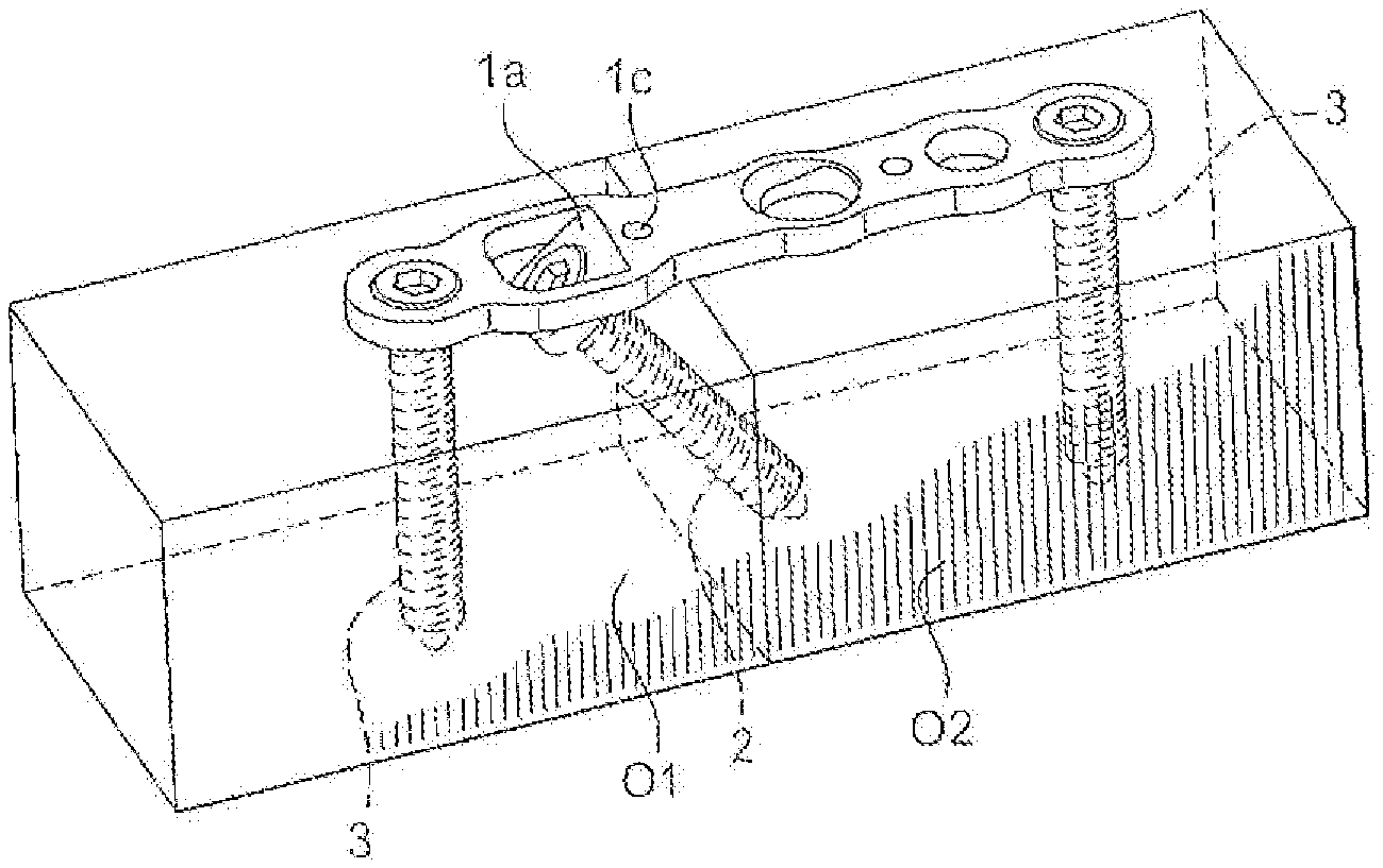
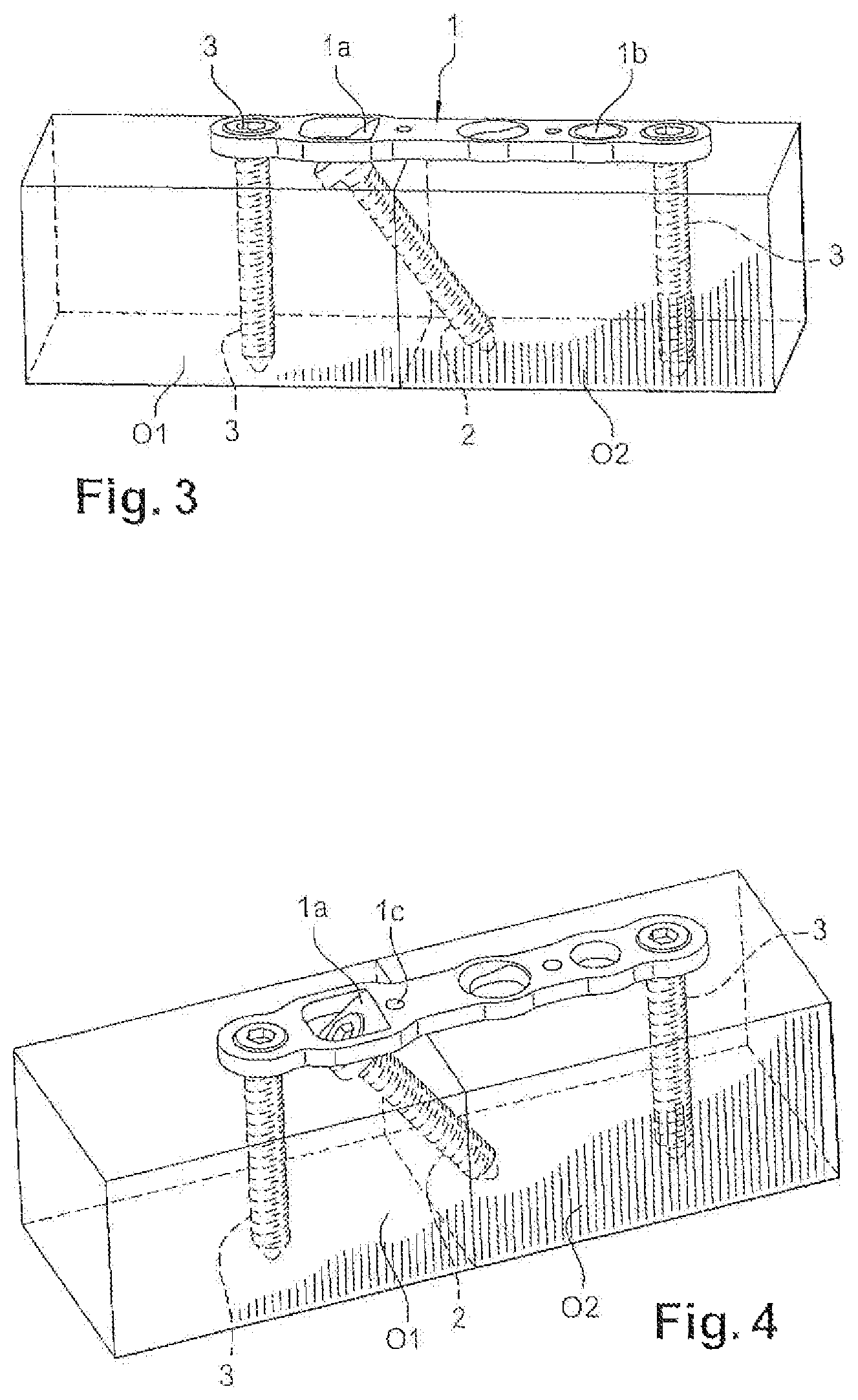
FIGS. 3 and 4 are perspective views showing the mounting of the plate between two bone parts and their orientation by means of the plate according to the invention, the bone parts being shown schematically.
DETAILED DESCRIPTION
According to the invention, the plate 1 has at least one formation 1a adapted to enable the positioning of at least one screw 2, at an angle a of between 30.degree. and 60.degree. with respect to a plane of the plate (FIG. 2).
In one embodiment, the formation 1a is an angled tab cut out and deformed from the plate. For example, the deformation is made with a cutting-punching operation. This angled tab has a hole 1a1 for screw 2. The angled tab 1a is positioned along the length of the plate so that after the screw 2 is fitted to it, the screw ensures the compression together of the two bone parts, as indicated below in the description.
In another embodiment, to allow for an angular orientation of the screw 2 according to an angle between about 30.degree. and 60.degree., the formation 1a can be formed as an angled hole. It must be noted that the tab 1a enables adaptation of the angle as a function of the pathology to be treated, given that it is possible to deform this tab at will. In other words, the angle can be adjusted over a few degrees directly by the surgeon in the operating room, using an appropriate tool.
With reference to FIGS. 3 and 4 that show the positioning of the plate 1 between two bone parts O1 and O2:
Once the osteotomies have been carried out, a template of the plate, which does not have a guide formation, enables the position of the tab to be determined.
After determining the position of the tab, the surgeon makes a corresponding recess with the appropriate rasp.
Once the plate having the tab has been positioned, the surgeon sets one or two screws 3, on a side of the site of the osteosynthesis or the arthrodesis toward the tab. A temporary fastening pin can, possibly, be positioned in a complementary lug.
The screw 2 is then engaged in the hole 1a1 of the tab 1a to place the fracture in compression.
Once the compression has been done, the surgeon can screw one or several other additional fastening screws 3 and remove the temporary pin.
In a known manner, this plate 1 has smooth and/or threaded holes for the fastening screws 3 set in the bone parts O1 and O2 to engage in, as shown in FIGS. 3 and 4.
Similarly, the plate 1 can have at least one hole 1c for a pin for temporarily positioning the plate 1. Advantageously, the plate 1 can have a guide 1c for the insertion of a pin on the side of one of the bone parts O1 and another guide 1d for the insertion of another pin on the side of the other bone part O2.
Considering the effect of the desired compression, such as indicated above, the guide 1c is a circular hole whose diameter corresponds substantially to that of the pin, whereas the other guide 1d can be an elongated slot.
These provisions thus enable the bone to slide under the plate 1 as the screws are set, while ensuring compression along a precise direction, generally axially or parallel to the plate. The pins are of any known and appropriate type, and perfectly known to one having ordinary skill in the art.
The plate 1 can have several shapes, so that the holes 1a in particular can be aligned or arrayed, all or in part, according to the corners of a triangle or of a quadrilateral. These provisions, in triangle or in quadrilateral, of the screws, improve the stability of the mounting.
It must be noted also that the plate 1, no matter its shape, can be longitudinally bent so as to adapt to the curvature of the bone, consequently enabling the screws to form an angle between them.
The advantages are readily apparent from the description.
* * * * *
D00000
D00001
D00002
XML
uspto.report is an independent third-party trademark research tool that is not affiliated, endorsed, or sponsored by the United States Patent and Trademark Office (USPTO) or any other governmental organization. The information provided by uspto.report is based on publicly available data at the time of writing and is intended for informational purposes only.
While we strive to provide accurate and up-to-date information, we do not guarantee the accuracy, completeness, reliability, or suitability of the information displayed on this site. The use of this site is at your own risk. Any reliance you place on such information is therefore strictly at your own risk.
All official trademark data, including owner information, should be verified by visiting the official USPTO website at www.uspto.gov. This site is not intended to replace professional legal advice and should not be used as a substitute for consulting with a legal professional who is knowledgeable about trademark law.