System and method for intent-based active callback management
Moller , et al. April 27, 2
U.S. patent number 10,992,811 [Application Number 16/836,798] was granted by the patent office on 2021-04-27 for system and method for intent-based active callback management. This patent grant is currently assigned to Virtual Hold Technology Solutions, LLC. The grantee listed for this patent is Virtual Hold Technology Solutions, LLC. Invention is credited to Matthew DiMaria, Brian Galvin, Nicholas James Kennedy, Shannon Lekas, Matthew Donaldson Moller, Kurt Nelson.


View All Diagrams
| United States Patent | 10,992,811 |
| Moller , et al. | April 27, 2021 |
System and method for intent-based active callback management
Abstract
A system and method for intent-based active callback management, utilizing a cloud callback system comprising at least a profile manager, callback manager, interaction manager, media server, and environment analyzer, allowing users to call businesses, agents in contact centers, or other users who are connected to a cloud callback system, and, failing to connect to the individual they called, allow for an automatic callback object to be created, whereby the two users may be automatically called and bridged together at a time when both users are available.
| Inventors: | Moller; Matthew Donaldson (Petaluma, CA), DiMaria; Matthew (Brentwood, TN), Lekas; Shannon (Cushing, TX), Nelson; Kurt (Thompsons Station, TN), Kennedy; Nicholas James (Akron, OH), Galvin; Brian (Silverdale, WA) | ||||||||||
|---|---|---|---|---|---|---|---|---|---|---|---|
| Applicant: |
|
||||||||||
| Assignee: | Virtual Hold Technology Solutions,
LLC (Akron, OH) |
||||||||||
| Family ID: | 1000005517826 | ||||||||||
| Appl. No.: | 16/836,798 | ||||||||||
| Filed: | March 31, 2020 |
Prior Publication Data
| Document Identifier | Publication Date | |
|---|---|---|
| US 20200366791 A1 | Nov 19, 2020 | |
Related U.S. Patent Documents
| Application Number | Filing Date | Patent Number | Issue Date | ||
|---|---|---|---|---|---|
| 16542577 | Aug 16, 2019 | 10609218 | |||
| 62820190 | Mar 18, 2019 | ||||
| Current U.S. Class: | 1/1 |
| Current CPC Class: | H04L 67/306 (20130101); H04M 3/5231 (20130101); H04M 3/5183 (20130101) |
| Current International Class: | H04M 3/523 (20060101); H04L 29/08 (20060101); H04M 3/51 (20060101) |
| Field of Search: | ;379/265.02,209.01,210.01,211.01,265.05,266.06,266.01,265.11 |
References Cited [Referenced By]
U.S. Patent Documents
| 6731625 | May 2004 | Eastep et al. |
| 7720091 | May 2010 | Faber et al. |
| 8588753 | November 2013 | Patino |
| 10152718 | December 2018 | Janefalkar |
| 10356091 | July 2019 | Kim et al. |
Attorney, Agent or Firm: Galvin; Brian R. Galvin Patent Law LLC
Parent Case Text
CROSS-REFERENCE TO RELATED APPLICATIONS
TABLE-US-00001 application No. Date Filed Title Current Herewith A SYSTEM AND METHOD FOR application INTENT- BASED ACTIVE CALLBACK MANAGEMENT which is a continuation of: 16/542,577 Aug. 16, 2019 A SYSTEM AND METHOD FOR INTENT- BASED ACTIVE CALLBACK MANAGEMENT which claims benefit of, and priority to: 62/820,190 Mar. 18, 2019 A SYSTEM AND METHOD FOR INTENT- BASED ACTIVE CALLBACK MANAGEMENT the entire specification of each of which is incorporated herein by reference.
Claims
What is claimed is:
1. A system for intent-based active callback management, comprising: a callback manager comprising at least a processor, a memory, and a first plurality of programming instructions stored in the memory and operating on the processor, wherein the first programming instructions, when operating on the processor, cause the processor to: receive a request for a callback to a callback recipient from a callback requester; instantiate a callback object; obtain environmental context for callback requester and callback recipient; update user profiles based on callback usage and performance patterns, as well as updates requested by users; determine a callback time, based at least on at least one user profile and the environmental context, and communicate it back to the callback recipient and the callback requester; connect the two parties, when the two first and second called parties are online, and delete the callback object; an interaction manager comprising at least a processor, a memory, and a first plurality of programming instructions stored in the memory and operating on the processor, wherein the first programming instructions, when operating on the processor, cause the processor to: call the other of a callback requester and callback recipient, when the first called party is online, as a second called party; connect the two parties, when the two first and second called parties are online, and delete the callback object; a media server comprising at least a processor, a memory, and a first plurality of programming instructions stored in the memory and operating on the processor, wherein the first programming instructions, when operating on the processor, cause the processor to: make calls and bridge them when appropriate, under control of the interaction manager; and an environment analyzer comprising at least a processor, a memory, and a first plurality of programming instructions stored in the memory and operating on the processor, wherein the first programming instructions, when operating on the processor, cause the processor to: analyze environment context data pertaining to the callback requester and the callback recipient.
2. The system of claim 1, further comprising a calendar server comprising at least a processor, a memory, and a first plurality of programming instructions stored in the memory and operating on the processor, wherein the first programming instructions, when operating on the processor, cause the processor to: interface with a plurality of user-specific calendars; and identify timeslots when the callback requester and recipient will both be available.
3. The system of claim 1, further comprising a brand interface server comprising at least a processor, a memory, and a first plurality of programming instructions stored in the memory and operating on the processor, wherein the first programming instructions, when operating on the processor, cause the processor to: connect to a plurality of external services; identify an external service to the callback manager; and expose any available APIs of the identified external service to the callback manager.
4. The system of claim 3, further comprising an intent analyzer comprising at least a processor, a memory, and a first plurality of programming instructions stored in the memory and operating on the processor, wherein the first programming instructions, when operating on the processor, cause the processor to: analyze a callback request to determine the context of the request; wherein the analysis comprises at least one operation drawn from the set of text analytics, speech-to-text transcription, audio analysis, facial recognition, expression analysis, and posture analysis.
5. The system of claim 1, further comprising a privacy server comprising at least a processor, a memory, and a first plurality of programming instructions stored in the memory and operating on the processor, wherein the first programming instructions, when operating on the processor, cause the processor to: identify a callback requestor; verify the callback requestor's identity against a trust configuration to determine whether the callback requestor is considered a trusted user; if the callback requestor is not a trusted user, deny the callback request; and encrypt at least one data stream involved in a callback.
6. The system of claim 1, further comprising a bot server comprising at least a processor, a memory, and a first plurality of programming instructions stored in the memory and operating on the processor, wherein the first programming instructions, when operating on the processor, cause the processor to: receive a plurality of callback parameters from the callback requestor; and provide the callback parameters to a callback manager.
7. The system of claim 1, further comprising an operations analyzer comprising at least a processor, a memory, and a first plurality of programming instructions stored in the memory and operating on the processor, wherein the first programming instructions, when operating on the processor, cause the processor to: determine a particular communication channel to use for a callback; monitor operation of components and communication channels involved in the callback; and if a component or communication channel of a callback cloud experiences a failure, select an alternate communication channel to complete the callback at a scheduled time.
8. The system of claim 4, further comprising a broker server comprising at least a processor, a memory, and a first plurality of programming instructions stored in the memory and operating on the processor, wherein the first programming instructions, when operating on the processor, cause the processor to: select a plurality of specific actions to take during a callback; and allocate each selected action to a system component involved in the callback.
9. A method for intent-based active callback management, comprising the steps of: receiving a request for a callback to a callback recipient from a callback requester; instantiate a callback object; retrieving user profiles for the callback requester and the callback recipient; obtaining environmental context for callback requester and callback recipient; determining a callback time based on at least one retrieved user profile and an environmental context, and communicating the determined callback time to the callback recipient and the callback requester; attempting a call to a first called party when a callback time arrives, the first called party being one of either the callback requester or callback recipient; calling as a second called party, the other of the callback requester and callback recipients, when the first called party is online; updating user profiles based on callback usage and performance patterns, as well as updates requested by users; and connecting the two first and second called parties when the second called party is online, and delete the callback object.
10. The method of claim 9, further including the steps of: obtaining a plurality of scheduled events from a calendar from the callback requester; and determining the callback time by determining when the requesting user is available for a callback, referencing the plurality of scheduled events.
11. The method of claim 9, further including the steps of: interfacing with a plurality of user-specific calendars using a calendar server; and identifying time slots when the callback requester and callback recipient will both be available.
12. The method of claim 9, further comprising the steps of: connecting to a plurality of external services using a brand interface server; identifying an external service to the callback manager; and exposing any available APIs of the identified external service to the callback manager.
13. The method of claim 12, further comprising the steps of: analyzing a callback request to determine the context of the request, using an intent analyzer; wherein the analysis comprises at least one operation drawn from the set of text analytics, speech-to-text transcription, audio analysis, facial recognition, expression analysis, and posture analysis.
14. The method of claim 9, further comprising the steps of: identifying a callback requestor, using a privacy server; verifying the callback requestor's identity against a trust configuration to determine whether the callback requestor is considered a trusted user; if the callback requestor is not a trusted user, denying the callback request; and encrypting at least one data stream involved in a callback.
15. The method of claim 9, further comprising the steps of: receiving a plurality of callback parameters from the callback requestor, using a bot server; and providing the callback parameters to a callback manager.
16. The method of claim 9, further comprising the steps of: determining a particular communication channel to use for a callback, using an operations analyzer; monitoring operation of components and communication channels involved in the callback; and if a component or communication channel of a callback cloud experiences a failure, selecting an alternate communication channel to complete the callback at a scheduled time.
17. The method of claim 13, further comprising the steps of: selecting a plurality of specific actions to take during a callback, using a broker server; and allocating each selected action to a system component involved in the callback.
Description
BACKGROUND OF THE INVENTION
Field of the Art
The disclosure relates to the field of contact center technology, specifically to the field of cloud-implemented automated callback systems.
Many businesses use groups of service representatives for communicating with clients who initiate communications with the business, such as by telephone calls. To most efficiently use the time and skills of each service representative, the service representatives may be organized into groups based on a skill set. For example, the groupings may be based on the representative's ability to handle client issues such as the opening of new accounts, billing issues and customer service issues on existing accounts.
Discussion of the State of the Art
Typically, if a client calls such a business, voice prompt menu choices enable the calling client to identify the issue for which the client requires service and the client is then queued for a service agent capable of handling the identified issue. As such, it is expected that clients who identify the purpose of their call as a "billing issue" will be queued for, and connected to, a service representative with the ability to handle billing issues. Similarly, it is expected that clients who identify the purpose of their call as a "customer service issue" will be queued for, and connected to, a service representative with the ability to handle customer service issues.
There are problems with existing communications systems, such as contact centers, including the following two problems. First, the voice prompt menus that are used to channel callers to the queue for the appropriate group of service agents are exacerbating to a client at best. It takes significant time to navigate the layered menus of voice prompts.
Second, waiting on-hold while a connection, be it a phone call, web chat, video conference, or other interaction type, is maintained in queue for connection to a service agent is also exacerbating to a client at best.
In an effort to reduce customer exacerbation caused by having to maintain a connection while on-hold in queue, secondary queue systems have been developed. A typical secondary queue system obtains a telephone number at which the calling client can be reached when a service representative is available (i.e., a call back number). The client disconnects, and then, at the proper time, a call back system establishes a connection to the client utilizing the call back number and couples the client to an available representative without waiting on-hold in queue. One exemplary system is disclosed in U.S. Pat. No. 6,563,921 to Williams et al. which is commonly assigned with the present application.
While such a system may make the experience of waiting for a connection to a service representative slightly less exasperating, it does not address the inconvenience of having to navigate an irritatingly slow and usually complicated voice prompt menu to enter the queue.
What is needed is a system and various methods for providing a callback cloud and related services that overcome the limitations of the prior art noted above.
SUMMARY OF THE INVENTION
Accordingly, the inventor has conceived and reduced to practice, in a preferred embodiment of the invention, a system and methods for intent-based active callback management. The following non-limiting summary of the invention is provided for clarity, and should be construed consistently with embodiments described in the detailed description below.
A system has been devised for intent-based active callback management, comprising: a profile manager comprising at least a processor, a memory, and a first plurality of programming instructions stored in the memory and operating on the processor, wherein the first programming instructions, when operating on the processor, cause the processor to: stores and maintains global user profiles; updates profiles based on callback usage and performance patterns, as well as updates requested by users; a callback manager comprising at least a processor, a memory, and a first plurality of programming instructions stored in the memory and operating on the processor, wherein the first programming instructions, when operating on the processor, cause the processor to: receiving a request for a callback to a callback recipient from a callback requester; instantiating a callback object; retrieving global profiles for the callback requester and the callback recipient from the profile manager; obtaining environmental context for callback requester and callback recipient; determining a callback time based on the profile and the environmental context and communicating it back to the callback recipient and the callback requester; connecting the two parties, when the two first and second called parties are online, and deleting the callback object; an interaction manager comprising at least a processor, a memory, and a first plurality of programming instructions stored in the memory and operating on the processor, wherein the first programming instructions, when operating on the processor, cause the processor to: calling the other of a callback requester and callback recipient, when the first called party is online, as a second called party; connecting the two parties, when the two first and second called parties are online, and deleting the callback object; a media server comprising at least a processor, a memory, and a first plurality of programming instructions stored in the memory and operating on the processor, wherein the first programming instructions, when operating on the processor, cause the processor to: make calls and bridge them when appropriate, under control of the interaction manager; and an environment analyzer comprising at least a processor, a memory, and a first plurality of programming instructions stored in the memory and operating on the processor, wherein the first programming instructions, when operating on the processor, cause the processor to: analyze environment context data pertaining to the callback requester and the callback recipient.
A method for intent-based active callback management has been devised, comprising the steps of: receiving a request for a callback to a callback recipient from a callback requester; instantiating a callback object; retrieving global profiles for the callback requester and the callback recipient; obtaining environmental context for callback requester and callback recipient; determining a callback time based on the profile and the environmental context, and communicating back to the callback recipient and the callback requester; attempting a call to a first called party when a callback time arrives, the first called party being one of either the callback requester or callback recipient; calling as a second called party, the other of the callback requester and callback recipients, when the first called party is online; and connecting the two first and second called parties when the second called party is online, and deleting the callback object.
BRIEF DESCRIPTION OF THE DRAWING FIGURES
The accompanying drawings illustrate several aspects and, together with the description, serve to explain the principles of the invention according to the aspects. It will be appreciated by one skilled in the art that the particular arrangements illustrated in the drawings are merely exemplary, and are not to be considered as limiting of the scope of the invention or the claims herein in any way.
FIG. 1 is a block diagram illustrating an exemplary system architecture for operating a callback cloud, according to one aspect.
FIG. 2 is a block diagram illustrating an exemplary system architecture for a callback cloud operating over a public switched telephone network and internet, to a variety of other brand devices and services, according to an embodiment.
FIG. 3 is a block diagram illustrating an exemplary system architecture for a callback cloud operating including a calendar server, over a public switched telephone network and internet, to a variety of other brand devices and services, according to an embodiment.
FIG. 4 is a block diagram illustrating an exemplary system architecture for a callback cloud operating including a brand interface server, over a public switched telephone network and internet, to a variety of other brand devices and services, according to an embodiment.
FIG. 5 is a block diagram illustrating an exemplary system architecture for a callback cloud operating including a brand interface server and intent analyzer, over a public switched telephone network and internet, to a variety of other brand devices and services, according to an embodiment.
FIG. 6 is a block diagram illustrating an exemplary system architecture for a callback cloud operating including a privacy server, over a public switched telephone network and internet, to a variety of other brand devices and services, according to an embodiment.
FIG. 7 is a block diagram illustrating an exemplary system architecture for a callback cloud operating including a bot server, over a public switched telephone network and internet, to a variety of other brand devices and services, according to an embodiment.
FIG. 8 is a block diagram illustrating an exemplary system architecture for a callback cloud operating including an operations analyzer over a public switched telephone network and internet, to a variety of other brand devices and services, according to an embodiment.
FIG. 9 is a block diagram illustrating an exemplary system architecture for a callback cloud including a brand interface server, an intent analyzer, and a broker server, operating over a public switched telephone network and internet, to a variety of other brand devices and services, according to an embodiment.
FIG. 10 is a diagram illustrating trust circles of levels of privacy for a user of a callback cloud, according to an aspect.
FIG. 11 is a method diagram illustrating the use of a callback cloud for intent-based active callback management, according to an embodiment.
FIG. 12 is a method diagram illustrating the use of a callback cloud for intent-based active callback management, including a calendar server, according to an embodiment.
FIG. 13 is a method diagram illustrating the use of a callback cloud for intent-based active callback management, including gathering of environmental context data of users, according to an embodiment.
FIG. 14 is a method diagram illustrating the use of a callback cloud for intent-based active callback management, including a brand interface server and intent analyzer, according to an embodiment.
FIG. 15 is a method diagram illustrating the use of a callback cloud for intent-based active callback management, including a privacy server, according to an embodiment.
FIG. 16 is a method diagram illustrating the use of a callback cloud for intent-based active callback management, including a bot server, according to an embodiment.
FIG. 17 is a method diagram illustrating the use of a callback cloud for intent-based active callback management, including an operations analyzer, according to an embodiment.
FIG. 18 is a method diagram illustrating the use of a callback cloud for intent-based active callback management, including a brand interface server, intent analyzer, and broker server, according to an embodiment.
FIG. 19 is a message flow diagram illustrating the exchange of messages and data between components of a callback cloud for intent-based active callback management, according to an embodiment.
FIG. 20 is a message flow diagram illustrating the exchange of messages and data between components of a callback cloud for intent-based active callback management, including a calendar server, according to an embodiment.
FIG. 21 is a message flow diagram illustrating the exchange of messages and data between components of a callback cloud for intent-based active callback management, including a brand interface server, according to an embodiment.
FIG. 22 is a message flow diagram illustrating the exchange of messages and data between components of a callback cloud for intent-based active callback management, including a brand interface server and intent analyzer, according to an embodiment.
FIG. 23 is a message flow diagram illustrating the exchange of messages and data between components of a callback cloud for intent-based active callback management, including a privacy server, according to an embodiment.
FIG. 24 is a message flow diagram illustrating the exchange of messages and data between components of a callback cloud for intent-based active callback management, including a bot server, according to an embodiment.
FIG. 25 is a message flow diagram illustrating the exchange of messages and data between components of a callback cloud for intent-based active callback management, including an operations analyzer, according to an embodiment.
FIG. 26 is a block diagram illustrating an exemplary hardware architecture of a computing device.
FIG. 27 is a block diagram illustrating an exemplary logical architecture for a client device.
FIG. 28 is a block diagram showing an exemplary architectural arrangement of clients, servers, and external services.
FIG. 29 is another block diagram illustrating an exemplary hardware architecture of a computing device.
FIG. 30 is a message flow diagram illustrating the exchange of messages and data between components of a callback cloud for intent-based active callback management, including a brand interface server, intent analyzer, and broker server, according to an embodiment.
DETAILED DESCRIPTION
The inventor has conceived, and reduced to practice, a system and method for intent-based active callback management.
One or more different aspects may be described in the present application. Further, for one or more of the aspects described herein, numerous alternative arrangements may be described; it should be appreciated that these are presented for illustrative purposes only and are not limiting of the aspects contained herein or the claims presented herein in any way. One or more of the arrangements may be widely applicable to numerous aspects, as may be readily apparent from the disclosure. In general, arrangements are described in sufficient detail to enable those skilled in the art to practice one or more of the aspects, and it should be appreciated that other arrangements may be utilized and that structural, logical, software, electrical and other changes may be made without departing from the scope of the particular aspects. Particular features of one or more of the aspects described herein may be described with reference to one or more particular aspects or figures that form a part of the present disclosure, and in which are shown, by way of illustration, specific arrangements of one or more of the aspects. It should be appreciated, however, that such features are not limited to usage in the one or more particular aspects or figures with reference to which they are described. The present disclosure is neither a literal description of all arrangements of one or more of the aspects nor a listing of features of one or more of the aspects that must be present in all arrangements.
Headings of sections provided in this patent application and the title of this patent application are for convenience only, and are not to be taken as limiting the disclosure in any way.
Devices that are in communication with each other need not be in continuous communication with each other, unless expressly specified otherwise. In addition, devices that are in communication with each other may communicate directly or indirectly through one or more communication means or intermediaries, logical or physical.
A description of an aspect with several components in communication with each other does not imply that all such components are required. To the contrary, a variety of optional components may be described to illustrate a wide variety of possible aspects and in order to more fully illustrate one or more aspects. Similarly, although process steps, method steps, algorithms or the like may be described in a sequential order, such processes, methods and algorithms may generally be configured to work in alternate orders, unless specifically stated to the contrary. In other words, any sequence or order of steps that may be described in this patent application does not, in and of itself, indicate a requirement that the steps be performed in that order. The steps of described processes may be performed in any order practical. Further, some steps may be performed simultaneously despite being described or implied as occurring non-simultaneously (e.g., because one step is described after the other step). Moreover, the illustration of a process by its depiction in a drawing does not imply that the illustrated process is exclusive of other variations and modifications thereto, does not imply that the illustrated process or any of its steps are necessary to one or more of the aspects, and does not imply that the illustrated process is preferred. Also, steps are generally described once per aspect, but this does not mean they must occur once, or that they may only occur once each time a process, method, or algorithm is carried out or executed. Some steps may be omitted in some aspects or some occurrences, or some steps may be executed more than once in a given aspect or occurrence.
When a single device or article is described herein, it will be readily apparent that more than one device or article may be used in place of a single device or article. Similarly, where more than one device or article is described herein, it will be readily apparent that a single device or article may be used in place of the more than one device or article.
The functionality or the features of a device may be alternatively embodied by one or more other devices that are not explicitly described as having such functionality or features. Thus, other aspects need not include the device itself.
Techniques and mechanisms described or referenced herein will sometimes be described in singular form for clarity. However, it should be appreciated that particular aspects may include multiple iterations of a technique or multiple instantiations of a mechanism unless noted otherwise. Process descriptions or blocks in figures should be understood as representing modules, segments, or portions of code which include one or more executable instructions for implementing specific logical functions or steps in the process. Alternate implementations are included within the scope of various aspects in which, for example, functions may be executed out of order from that shown or discussed, including substantially concurrently or in reverse order, depending on the functionality involved, as would be understood by those having ordinary skill in the art.
Definitions
"Callback" as used herein refers to an instance of an individual being contacted after their initial contact was unsuccessful. For instance, if a first user calls a second user on a telephone, but the second user does not receive their call for one of numerous reasons including turning off their phone or simply not picking up, the second user may then place a callback to the first user once they realize they missed their call. This callback concept applies equally to many forms of interaction that need not be restricted to telephone calls, for example including (but not limited to) voice calls over a telephone line, video calls over a network connection, or live text-based chat such as web chat or short message service (SMS) texting. While a callback (and various associated components, methods, and operations taught herein) may also be used with an email communication despite the inherently asynchronous nature of email (participants may read and reply to emails at any time, and need not be interacting at the same time or while other participants are online or available), the preferred usage as taught herein refers to synchronous communication (that is, communication where participants are interacting at the same time, as with a phone call or chat conversation).
"Callback object" as used herein means a data object representing callback data, such as the identities and call information for a first and second user, the parameters for a callback including what time it shall be performed, and any other relevant data for a callback to be completed based on the data held by the callback object.
"Latency period" as used herein refers to the period of time between when a Callback Object is created and the desired Callback is initiated, for example, if a callback object is created and scheduled for a time five hours from the creation of the object, and the callback initiates on-time in five hours, the latency period is equal to the five hours between the callback object creation and the callback initiation.
"Brand" as used herein means a possible third-party service or device that may hold a specific identity, such as a specific MAC address, IP address, a username or secret key which can be sent to a cloud callback system for identification, or other manner of identifiable device or service that may connect with the system. Connected systems or services may include a Private Branch Exchange ("PBX"), call router, chat server which may include text or voice chat data, a Customer Relationship Management ("CRM") server, an Automatic Call Distributor ("ACD"), or a Session Initiation Protocol ("SIP") server.
Conceptual Architecture
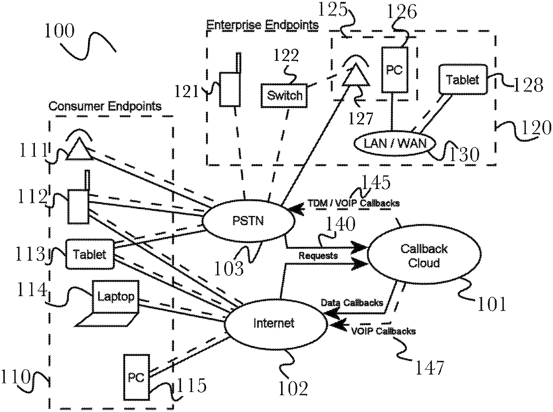
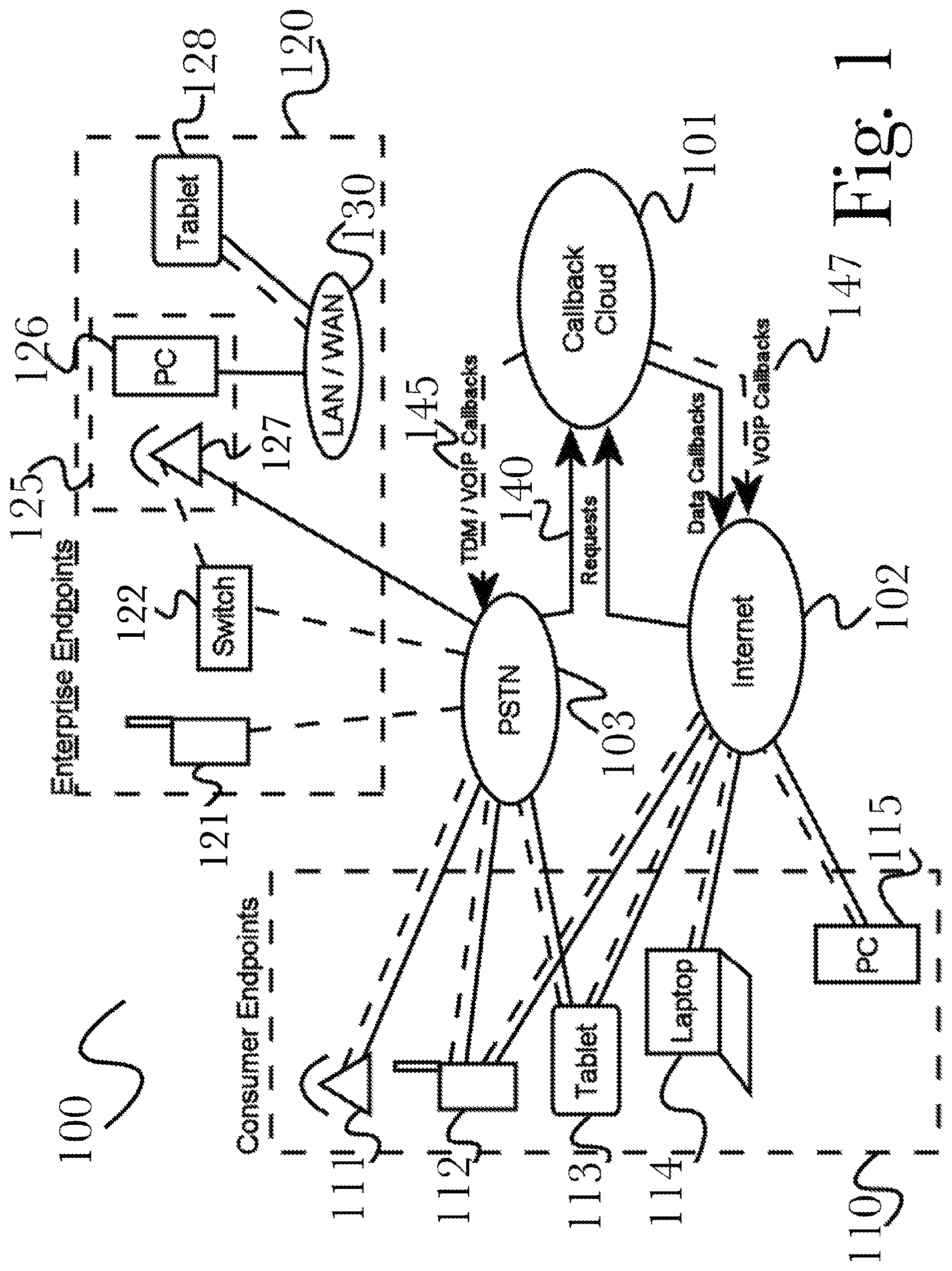
FIG. 1 is a block diagram of a preferred embodiment of the invention, illustrating an exemplary architecture of a system 100 for providing a callback cloud service. According to the embodiment, callback cloud 101 may receive requests 140 via a plurality of communications networks such as a public switched telephone network (PSTN) 103 or the Internet 102. These requests may comprise a variety of communication and interaction types, for example including (but not limited to) voice calls over a telephone line, video calls over a network connection, or live text-based chat such as web chat or short message service (SMS) texting via PSTN 103. Such communications networks may be connected to a plurality of consumer endpoints 110 and enterprise endpoints 120 as illustrated, according to the particular architecture of communication network involved. Exemplary consumer endpoints 110 may include, but are not limited to, traditional telephones 111, cellular telephones 112, mobile tablet computing devices 113, laptop computers 114, or desktop personal computers (PC) 115. Such devices may be connected to respective communications networks via a variety of means, which may include telephone dialers, VOIP telecommunications services, web browser applications, SMS text messaging services, or other telephony or data communications services. It will be appreciated by one having ordinary skill in the art that such means of communication are exemplary, and many alternative means are possible and becoming possible in the art, any of which may be utilized as an element of system 100 according to the invention.
A PSTN 103 or the Internet 102 (and it should be noted that not all alternate connections are shown for the sake of simplicity, for example a desktop PC 126 may communicate via the Internet 102) may be further connected to a plurality of enterprise endpoints 120, which may comprise cellular telephones 121, telephony switch 122, desktop environment 125, internal Local Area Network (LAN) or Wide-Area Network (WAN) 130, and mobile devices such as tablet computing device 128. As illustrated, desktop environment 125 may include both a telephone 127 and a desktop computer 126, which may be used as a network bridge to connect a telephony switch 122 to an internal LAN or WAN 130, such that additional mobile devices such as tablet PC 128 may utilize switch 122 to communicate with PSTN 102. Telephone 127 may be connected to switch 122 or it may be connected directly to PSTN 102. It will be appreciated that the illustrated arrangement is exemplary, and a variety of arrangements that may comprise additional devices known in the art are possible, according to the invention.
Callback cloud 101 may respond to requests 140 received from communications networks with callbacks appropriate to the technology utilized by such networks, such as data or Voice over Internet Protocol (VOIP) callbacks 145, 147 sent to Internet 102, or time-division multiplexing (TDM) such as is commonly used in cellular telephony networks such as the Global System for Mobile Communications (GSM) cellular network commonly used worldwide, or VOIP callbacks to PSTN 103. Data callbacks 147 may be performed over a variety of Internet-enabled communications technologies, such as via e-mail messages, application pop-ups, or Internet Relay Chat (IRC) conversations, and it will be appreciated by one having ordinary skill in the art that a wide variety of such communications technologies are available and may be utilized according to the invention. VOIP callbacks may be made using either, or both, traditional telephony networks such as PSTN 103 or over VOIP networks such as Internet 102, due to the flexibility to the technology involved and the design of such networks. It will be appreciated that such callback methods are exemplary, and that callbacks may be tailored to available communications technologies according to the invention.
Additionally, callback cloud 101 may receive estimated wait time (EWT) information from an enterprise 120 such as a contact center. This information may be used to estimate the wait time for a caller before reaching an agent (or other destination, such as an automated billing system), and determine whether to offer a callback proactively before the customer has waited for long. EWT information may also be used to select options for a callback being offered, for example to determine availability windows where a customer's callback is most likely to be fulfilled (based on anticipated agent availability at that time), or to offer the customer a callback from another department or location that may have different availability. This enables more detailed and relevant callback offerings by incorporating live performance data from an enterprise, and improves customer satisfaction by saving additional time with preselected recommendations and proactively-offered callbacks.
FIG. 2 is a block diagram illustrating an exemplary system architecture for a callback cloud operating over a public switched telephone network and the Internet, and connecting to a variety of other brand devices and services, according to an embodiment. A collection of user brands 210 may be present either singly or in some combination, possibly including a Public Branch Exchange ("PBX") 211, a Session Initiation Protocol ("SIP") server 212, a Customer Relationship Management ("CRM") server 213, a call router 214, or a chat server 215, or some combination of these brands. These brands 210 may communicate over a combination of, or only one of, a Public Switched Telephone Network ("PSTN") 103, and the Internet 102, to communicate with other devices including a callback cloud 220, a company phone 121, or a personal cellular phone 112. A SIP server 212 is responsible for initiating, maintaining, and terminating sessions of voice, video, and text or other messaging protocols, services, and applications, including handling of PBX 211 phone sessions, CRM server 213 user sessions, and calls forwarded via a call router 214, all of which may be used by a business to facilitate diverse communications requests from a user or users, reachable by phone 121, 112 over either PSTN 103 or the Internet 102. A chat server 215 may be responsible for maintaining one or both of text messaging with a user, and automated voice systems involving technologies such as an Automated Call Distributor ("ACD"), forwarding relevant data to a call router 214 and CRM server 213 for further processing, and a SIP server 212 for generating communications sessions not run over the PSTN 103. Various systems may also be used to monitor their respective interactions (for example, chat session by a chat server 215 or phone calls by an ACD or SIP server 212), to track agent and resource availability for producing EWT estimations.
When a user calls from a mobile device 112 or uses some communication application such as (for example, including but not limited to) SKYPE.TM. or instant messaging, which may also be available on a laptop or other network endpoint other than a cellular phone 112, they may be forwarded to brands 210 operated by a business in the manner described herein. For example, a cellular phone call my be placed over PSTN 103 before being handled by a call router 214 and generating a session with a SIP server 212, the SIP server creating a session with a callback cloud 220 with a profile manager 221 if the call cannot be completed, resulting in a callback being required. A profile manager 221 manages the storage, retrieval, and updating of user profiles, including global and local user profiles. The profile manager 221, which may be located in a callback cloud 220 receives initial requests to connect to callback cloud 220, and forwards relevant user profile information to a callback manager 223, which may further request environmental context data from an environment analyzer 222. Environmental context data may include (for example, and not limited to) recorded information about when a callback requester or callback recipient may be suspected to be driving or commuting from work, for example, and may be parsed from online profiles or online textual data, using an environment analyzer 222.
A callback manager 223 centrally manages all callback data, creating a callback programming object which may be used to manage the data for a particular callback, and communicates with an interaction manager 224 which handles requests to make calls and bridge calls, which go out to a media server 225 which actually makes the calls as requested. For example, interaction manager 224 may receive a call from a callback requester, retrieve callback parameters for that callback requester from the callback manager 223, and cause the media server 225 to make a call to a callback recipient while the callback requester is still on the line, thus connecting the two parties. After the call is connected, the callback programming object used to make the connection may be deleted. The interaction manager 224 may subsequently provide changed callback parameters to the callback manager 223 for use or storage. In this way, the media server 225 may be altered in the manner in which it makes and bridges calls when directed, but the callback manager 223 does not need to adjust itself, due to going through an intermediary component, the interaction manager 224, as an interface between the two. A media server 225, when directed, may place calls and send messages, emails, or connect voice over IP ("VoIP") calls and video calls, to users over a PSTN 103 or the Internet 102. Callback manager 223 may work with a user's profile as managed by a profile manager 221, with environmental context from an environment analyzer 222 as well as (if provided) EWT information for any callback recipients (for example, contact center agents with the appropriate skills to address the callback requestor's needs, or online tech support agents to respond to chat requests), to determine an appropriate callback time for the two users (a callback requestor and a callback recipient), interfacing with an interaction manager 224 to physically place and bridge the calls with a media server 225. In this way, a user may communicate with another user on a PBX system 211, or with automated services hosted on a chat server 215, and if they do not successfully place their call or need to be called back by a system, a callback cloud 220 may find an optimal time to bridge a call between the callback requestor and callback recipient, as necessary.
FIG. 3 is a block diagram illustrating an exemplary system architecture for a callback cloud including a calendar server operating over a public switched telephone network and the Internet, and connected to a variety of other brand devices and services, according to an embodiment. According to this embodiment, many user brands 310 are present, including PBX system 311, a SIP server 312, a CRM server 313, a call router 314, and a chat server 315, which may be connected variously to each other as shown, and connected to a PSTN 103 and the Internet 102, which further connect to a cellular phone 112 and a landline 121 or other phone that may not have internet access. As further shown, callback cloud 320 contains multiple components, including a calendar server 321, profile manager 322, environment analyzer 323, callback manager 324, interaction manager 325, and media server 326, which similarly to user brands 310 may be interconnected in various ways as depicted in the diagram, and connected to either a PSTN 103 or the internet 102.
A calendar server 321, according to the embodiment, is a server which may store and retrieve, either locally or from internet-enabled services associated with a user, calendars which hold data on what times a user may be available or busy (or some other status that may indicate other special conditions, such as to allow only calls from certain sources) for a callback to take place. A calendar server 321 connects to the internet 102, and to a profile manager 322, to determine the times a callback requestor and callback recipient may both be available.
FIG. 4 is a block diagram illustrating an exemplary system architecture for a callback cloud including a brand interface server, operating over a public switched telephone network and the Internet, and connected to a variety of other brand devices and services, according to an embodiment. According to this embodiment, many user brands 410 are present, including PBX system 411, a SIP server 412, a CRM server 413, a call router 414, and a chat server 415, which may be connected variously to each other as shown, and connected to a PSTN 103 and the Internet 102, which further connect to a cellular phone 112 and a landline 121 or other phone that may not have internet access. As further shown, callback cloud 420 contains multiple components, including a profile manager 421, environment analyzer 422, callback manager 423, interaction manager 424, and media server 425, which similarly to user brands 410 may be interconnected in various ways as depicted in the diagram, and connected to either a PSTN 103 or the internet 102.
Present in this embodiment is a brand interface server 430, which may expose the identity of, and any relevant API's or functionality for, any of a plurality of connected brands 410, to elements in a callback cloud 420. In this way, elements of a callback cloud 420 may be able to connect to, and interact more directly with, systems and applications operating in a business' infrastructure such as a SIP server 412, which may be interfaced with a profile manager 421 to determine the exact nature of a user's profiles, sessions, and interactions in the system for added precision regarding their possible availability and most importantly, their identity.
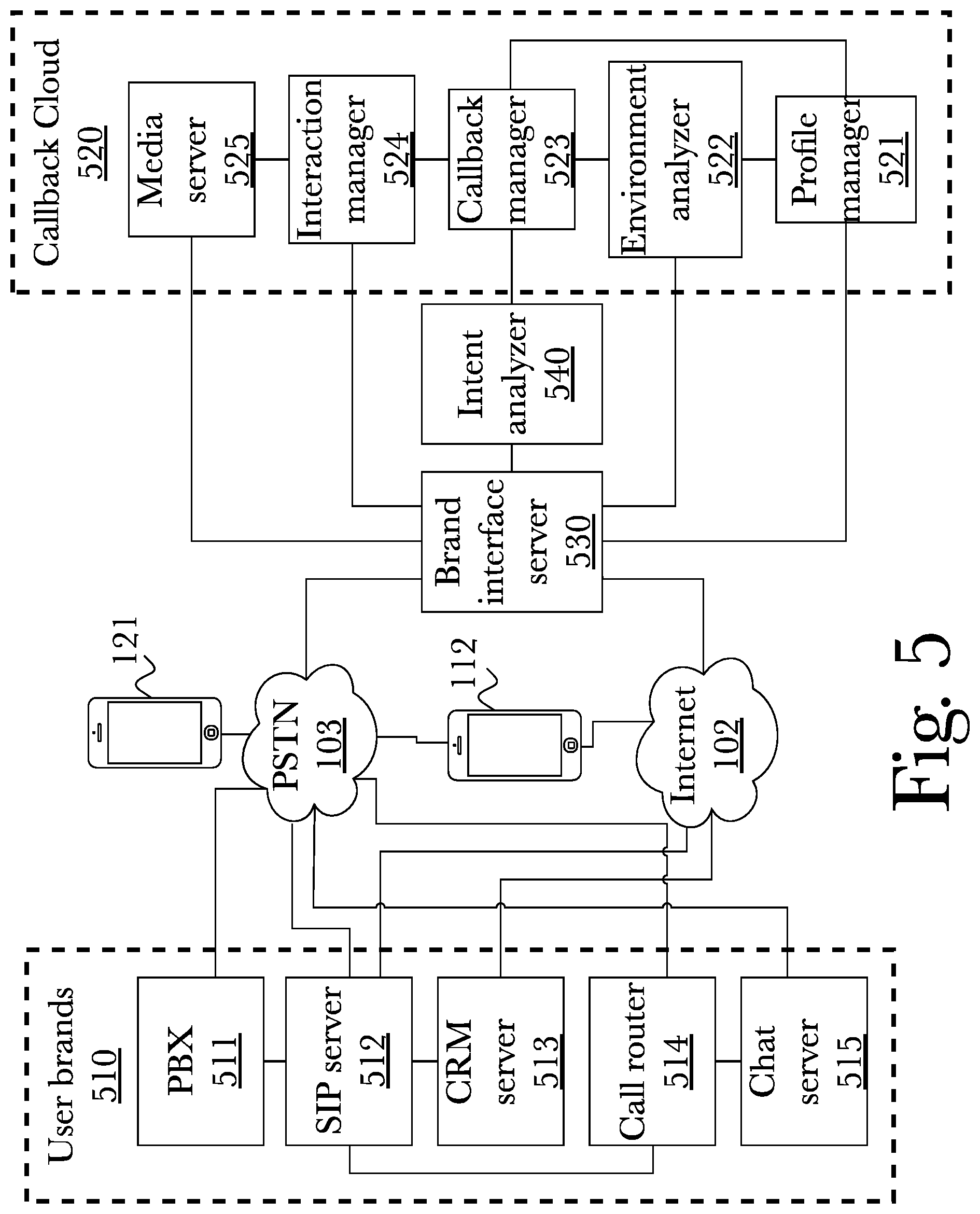
FIG. 5 is a block diagram illustrating an exemplary system architecture for a callback cloud including a brand interface server and intent analyzer, operating over a public switched telephone network and the Internet, and connected to a variety of other brand devices and services, according to an embodiment. According to this embodiment, many user brands 510 are present, including PBX system 511, a SIP server 512, a CRM server 513, a call router 514, and a chat server 515, which may be connected variously to each other as shown, and connected to a PSTN 103 and the Internet 102, which further connect to a cellular phone 112 and a landline 121 or other phone that may not have internet access. Further shown is a callback cloud 520 contains multiple components, including a profile manager 521, environment analyzer 522, callback manager 523, interaction manager 524, and media server 525, which similarly to user brands 510 may be interconnected in various ways as depicted in the diagram, and connected to either a PSTN 103 or the internet 102.
Present in this embodiment is a brand interface server 530, which may expose the identity of, and any relevant API's or functionality for, any of a plurality of connected brands 510, to elements in a callback cloud 520. In this way, elements of a callback cloud 520 may be able to connect to, and interact more directly with, systems and applications operating in a business' infrastructure such as a SIP server 512, which may be interfaced with a profile manager 521 to determine the exact nature of a user's profiles, sessions, and interactions in the system for added precision regarding their possible availability and most importantly, their identity. Also present in this embodiment is an intent analyzer 540, which analyzes spoken words or typed messages from a user that initiated the callback request, to determine their intent for a callback. For example, their intent may be to have an hour-long meeting, which may factor into the decision by a callback cloud 520 to place a call shortly before one or both users may be required to start commuting to or from their workplace. Intent analysis may utilize any combination of text analytics, speech-to-text transcription, audio analysis, facial recognition, expression analysis, posture analysis, or other analysis techniques, and the particular technique or combination of techniques may vary according to such factors as the device type or interaction type (for example, speech-to-text may be used for a voice-only call, while face/expression/posture analysis may be appropriate for a video call), or according to preconfigured settings (that may be global, enterprise-specific, user-specific, device-specific, or any other defined scope).
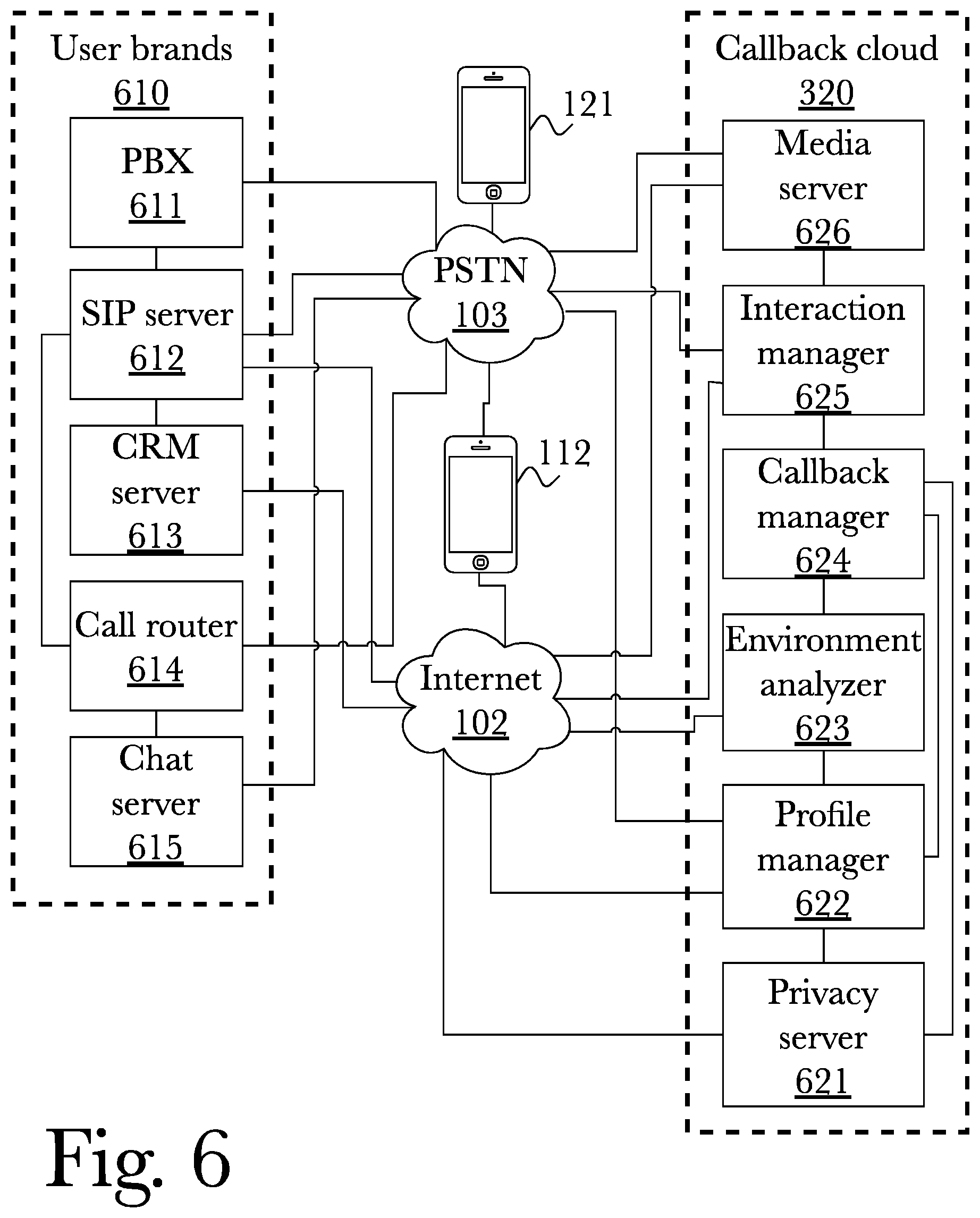
FIG. 6 is a block diagram illustrating an exemplary system architecture for a callback cloud including a privacy server, operating over a public switched telephone network and the Internet, and connected to a variety of other brand devices and services, according to an embodiment. According to this embodiment, many user brands 610 are present, including PBX system 611, a SIP server 612, a CRM server 613, a call router 614, and a chat server 615, which may be connected variously to each other as shown, and connected to a PSTN 103 and the Internet 102, which further connect to a cellular phone 112 and a landline 121 or other phone that may not have internet access. As further shown, a callback cloud 620 contains multiple components, including a profile manager 622, environment analyzer 623, callback manager 624, interaction manager 625, and media server 626, which similarly to user brands 610 may be interconnected in various ways as depicted in the diagram, and connected to either a PSTN 103 or the internet 102.
In this embodiment, a privacy server 621 may connect to the internet 102, and to a profile manager 622 as well as a callback manager 624, and allows for callback requestors to first be validated using trust-circles to determine if they are a trusted user. A trusted user may be defined using a variety of criteria (that may vary according to the user, interaction, device, enterprise, or other context), and may for example comprise a determination of whether the callback requestor is a friend or family member, or is using a trusted brand such as a piece of equipment from the same company that the callback recipient works at, or if the callback requestor is untrusted or is contacting unknown recipients, to determine if a callback request is permitted based on user settings. Further, a privacy server 621 may encrypt one or both of incoming and outgoing data from a callback manager 624 in such a way as to ensure that, for example, a callback recipient might not know who requested the callback, or their profile may not be visible to the recipient, or vice versa, and other privacy options may also be enabled as needed by a corporation. Encryption may utilize public or private keys, or may utilize perfect forward secrecy (such that even the enterprise routing the call cannot decrypt it), or other encryption schema or combinations thereof that may provide varying features or degrees of privacy, security, or anonymity (for example, one enterprise may permit anonymous callbacks while another may require a user to identify themselves and may optionally verify this identification).
FIG. 7 is a block diagram illustrating an exemplary system architecture for a callback cloud including a bot server, operating over a public switched telephone network and the Internet, and connected to a variety of other brand devices and services, according to an embodiment. According to this embodiment, many user brands 710 are present, including PBX system 711, a SIP server 712, a CRM server 713, a call router 714, and a chat server 715, which may be connected variously to each other as shown, and connected to a PSTN 103 and the Internet 102, which further connect to a cellular phone 112 and a landline 121 or other phone that may not have internet access. As further shown, a callback cloud 720 contains multiple components, including a profile manager 721, environment analyzer 722, callback manager 723, interaction manager 725, and media server 726, which similarly to user brands 710 may be interconnected in various ways as depicted in the diagram, and connected to either a PSTN 103 or the internet 102.
In the present embodiment, a bot server 724 also is present in a callback cloud 720, which allows for communication with a callback requestor. Bot server 724 allows a user to specify, through any available data type such as (including, but not limited to) SMS texting, email, or audio data, any desired parameters for the callback they would like to request. This is similar to an ACD system used by individual call-centers, but exists as a separate server 724 in a cloud service 720 which may then be configured as-needed by a hosting company, and behaves akin to an automated secretary, taking user information down to specify a callback at a later time from the callback recipient.
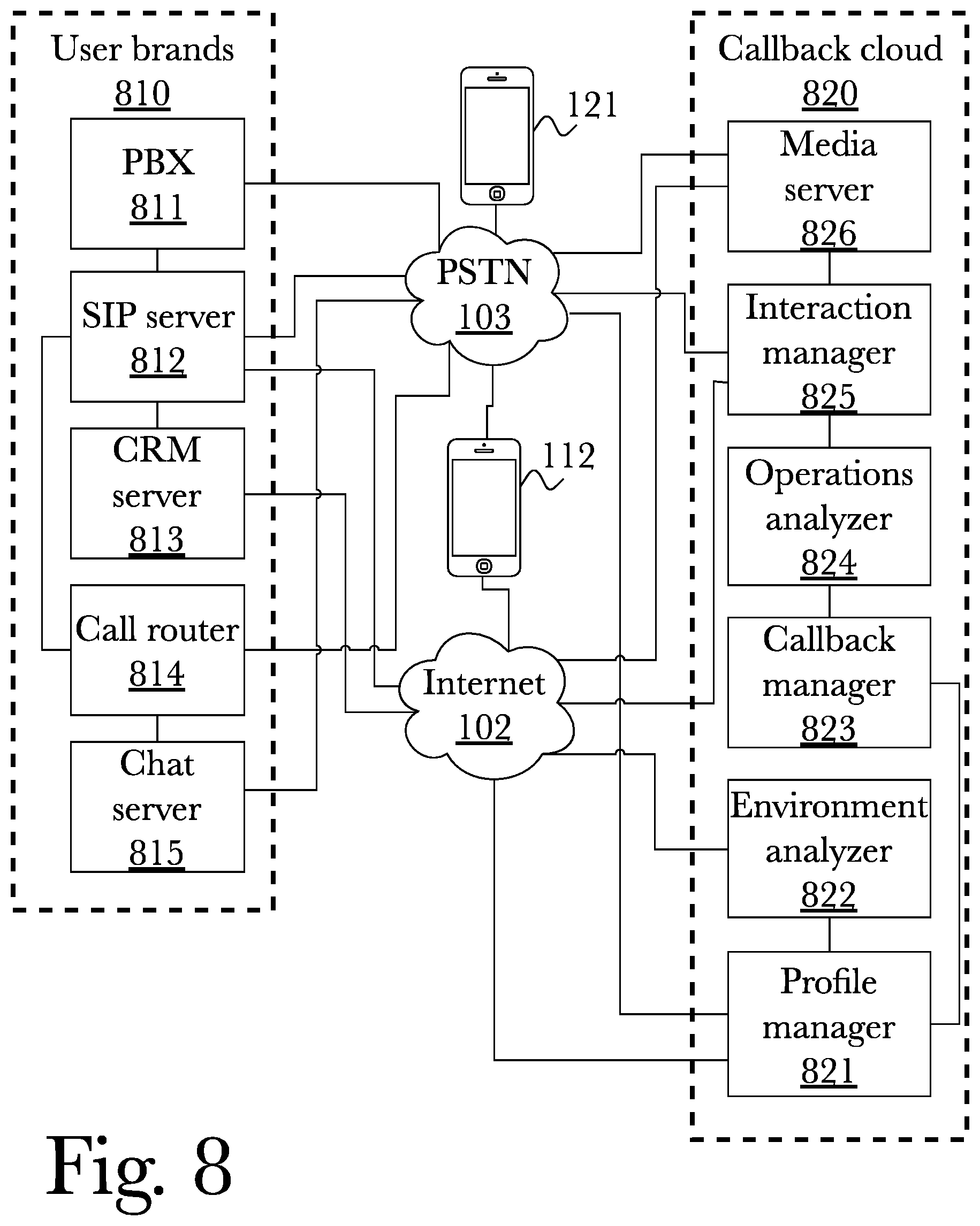
FIG. 8 is a block diagram illustrating an exemplary system architecture for a callback cloud including an operations analyzer operating over a public switched telephone network and the Internet, and connected to a variety of other brand devices and services, according to an embodiment. According to this embodiment, many user brands 810 are present, including PBX system 811, a SIP server 812, a CRM server 813, a call router 814, and a chat server 815, which may be connected variously to each other as shown, and connected to a PSTN 103 and the Internet 102, which further connect to a cellular phone 112 and a landline 121 or other phone that may not have internet access. As further shown, a callback cloud 820 contains multiple components, including a profile manager 821, environment analyzer 822, callback manager 823, interaction manager 825, and media server 826, which similarly to user brands 810 may be interconnected in various ways as depicted in the diagram, and connected to either a PSTN 103 or the internet 102.
In this embodiment, an operations analyzer 824 is present, which may determine a particular channel to be used to reach a callback recipient and callback requestor, for example (and not limited to), VoIP services such as SKYPE.TM. or DISCORD.TM., a PSTN phone connection, any particular phone number or user accounts to connect using, or other service, to determine the optimal method with which to reach a user during a callback. An operations analyzer 824 may also analyze and determine the points of failure in a callback cloud 820, if necessary, for example if a callback attempt fails to connect operations analyzer 824 may bridge a callback requestor and recipient using an alternate communication channel to complete the callback at the scheduled time.
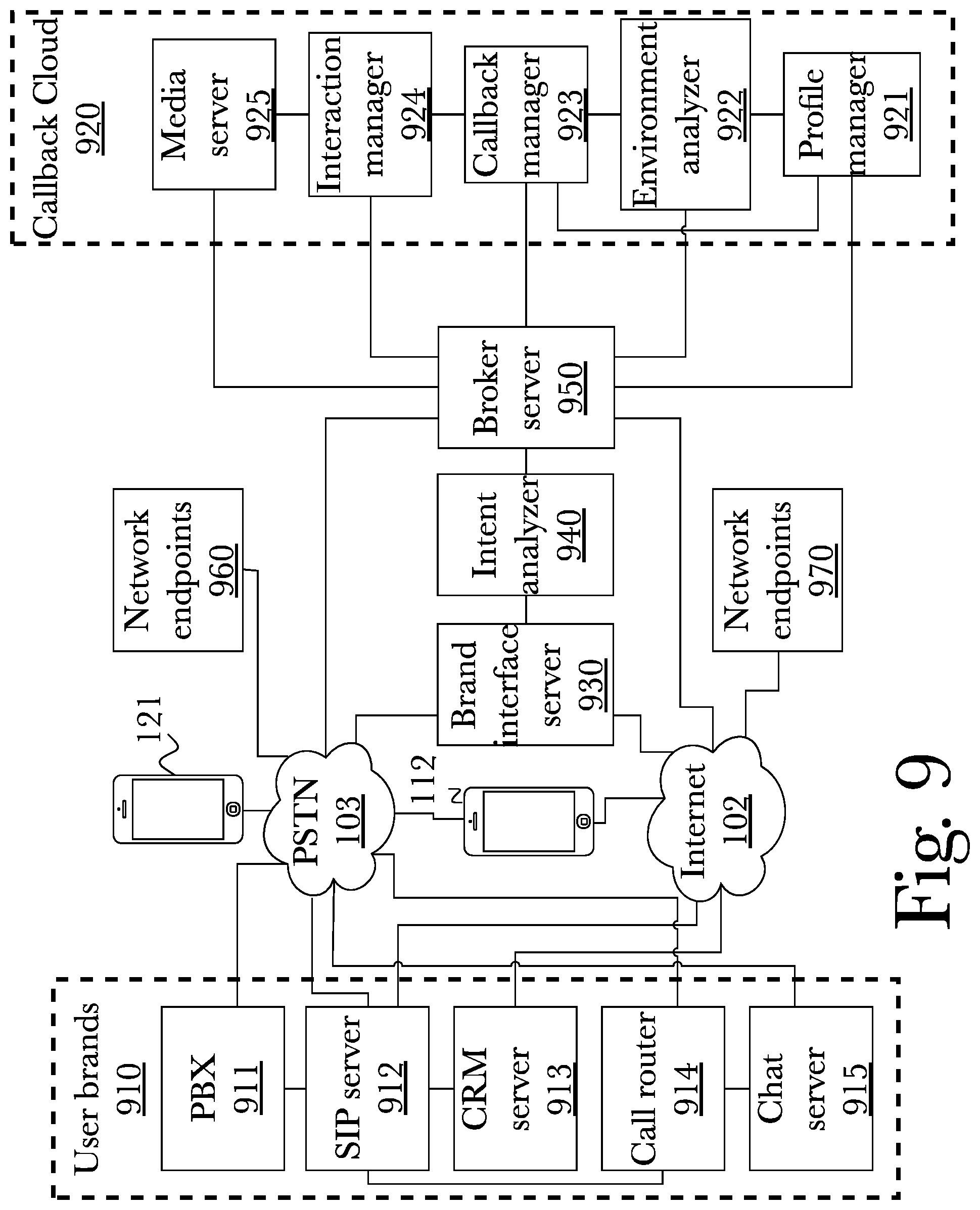
FIG. 9 is a block diagram illustrating an exemplary system architecture for a callback cloud including a brand interface server, an intent analyzer, and a broker server, operating over a public switched telephone network and internet, and connected to a variety of other brand devices and services, according to an embodiment. According to this embodiment, many user brands 910 are present, including PBX system 911, a SIP server 912, a CRM server 913, a call router 914, and a chat server 915, which may be connected variously to each other as shown, and connected to a PSTN 103 and the Internet 102, which further connect to a cellular phone 112 and a landline 121 or other phone that may not have internet access. As further shown, a callback cloud 920 contains multiple components, including a profile manager 921, environment analyzer 922, callback manager 923, interaction manager 924, and media server 925, which similarly to user brands 910 may be interconnected in various ways as depicted in the diagram, and connected to either a PSTN 103 or the internet 102. Also present are a plurality of network endpoints 960, 970, connected to either or both of the internet 102 and a PSTN 103, such network endpoints representing contact points other than a landline 121 or cell phone 112, including laptops, desktops, tablet computers, or other communication devices.
Present in this embodiment is a brand interface server 930, which may expose the identity of, and any relevant API's or functionality for, any of a plurality of connected brands 910, to an intent analyzer 940. In this way, elements of a callback cloud 920 may be able to connect to, and interact more directly with, systems and applications operating in a business' infrastructure such as a SIP server 912, which may be interfaced with a profile manager 921 to determine the exact nature of a user's profiles, sessions, and interactions in the system for added precision regarding their possible availability and most importantly, their identity. An intent analyzer 940 may analyze spoken words or typed messages from a user that initiated the callback request, to determine their intent for a callback, as well as forward data received from a brand interface server. For example, their intent may be to have an hour-long meeting, which may factor into the decision by a callback cloud 920 to place a call shortly before one or both users may be required to start commuting to or from their workplace. An intent analyzer 940 may forward all data through a broker server 950 which may allocate specific actions and responses to take between third-party brands 910 and callback cloud 920 components, as needed, as well as forward all data from the exposed and interfaced elements with the callback cloud 920.
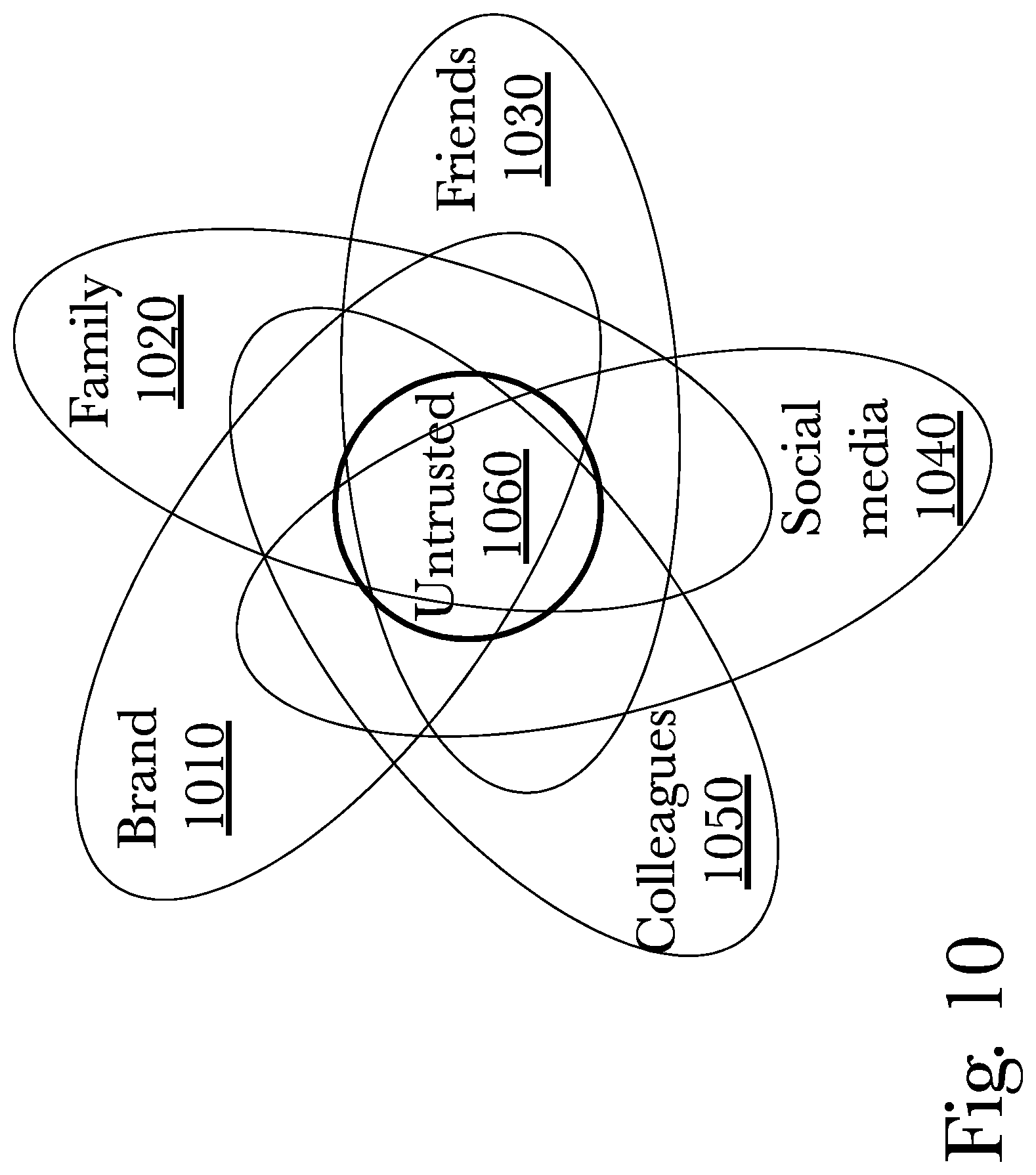
FIG. 10 is a diagram illustrating trust circles of levels of privacy for a user of a callback cloud, according to an aspect. These trust circles are data constructs enforced by a privacy server 621 which are determined with a profile manager 622, which indicate the level of trust that callers may possess, and therefore the system's ability to schedule a callback with the caller and the recipient. A caller who calls from a recognized brand 1010, for example a company's phone forwarded through their PBX 611, may be recognized as having the highest level of trust, due to coming from a recognized source within the same organization. Family 1020 may (for example) be the second highest level of trust, allowing for just as many privileges with callbacks, or perhaps restricting callback requests to only certain hours, to prevent users from being disrupted during certain work hours. A callback recipient's friends 1030 may occupy a level of trust lower than that of family, representing users less-trusted than family 1020 callers, and may yet have more restricted access to making callback requests for a user, and a continuing, descending hierarchy may be used to model additional levels of trust. For example, additional trust levels may include (but are not limited to) social media 1040 recognized users, colleagues 1050 which may represent individuals only loosely affiliated with a potential callback recipient, and untrusted 1060, representing users who are known to the system and deemed banned or untrustworthy, having the lowest ability to request an automated callback connection with a user. A further level of trust may exist, outside of the trust-circle paradigm, representing unknown contacts 1070, which, depending on the settings for an individual user or an organization using a callback cloud system 620, may be unable to request callbacks, or may only be able to request callbacks at certain restricted hours until they are set to a higher level of trust in the system, according to a preferred embodiment.
As shown in FIG. 10, trust circles need not be implicitly hierarchical in nature and may overlap in various ways similar to a logical Venn diagram. For example one individual may be a friend and also known on social media, or someone may be both family and a colleague (as is commonplace in family businesses or large companies that may employ many people). As shown, anybody may be considered "untrusted" regardless of their other trust groupings, for example if a user does not wish to receive callbacks from a specific friend or coworker. While the arrangement shown is one example, it should be appreciated that a wide variety of numerous overlapping configuration may be possible with arbitrary complexity, as any one person may be logically placed within any number of groups as long as the trust groupings themselves are not exclusive (such as a group for coworkers and one for individuals outside the company).
Expanding on the notion of trust circles, there may also be logical "ability" circles that correspond to various individuals' capabilities and appropriateness for various issues, such as (for example) tech support skill or training with specific products, or whether a member of a brand 1010 is actually a member of the best brand to handle a specific reason for a callback, based on the callback request context. For example, a customer requesting a callback for assistance with booking a flight may not be adequately served by employees of airlines that don't offer flights to their intended destination, so combining the brand trust zone 1010 with a capability map would indicate to the callback system which individuals are more appropriate for the callback in question. This expands from merely trusting certain users and discarding others, to a form of automated virtual concierge service that finds the user for a callback request that is most capable and relevant to the request, ensuring optimum handling of the callback requestor's needs.
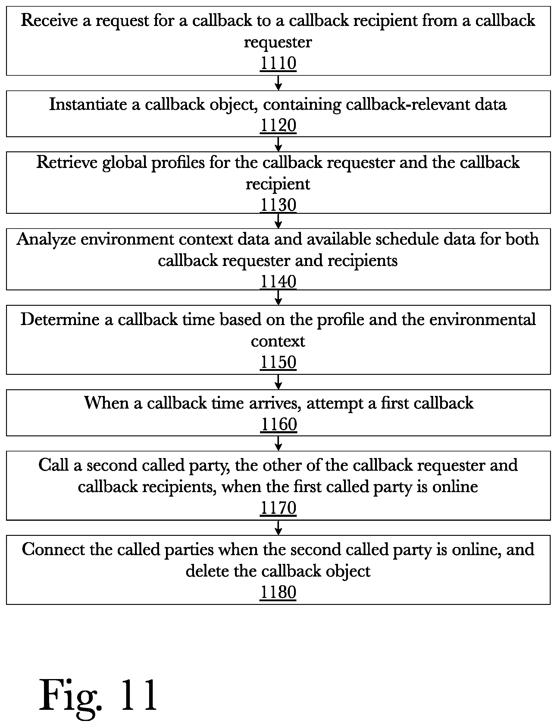
FIG. 11 is a method diagram illustrating the use of a callback cloud for intent-based active callback management, according to an embodiment. According to an embodiment, a callback cloud 220 must receive a request for a callback to a callback recipient, from a callback requester 1110. This refers to an individual calling a user of a cloud callback system 220, being unable to connect for any reason, and the system allowing the caller to request a callback, thus becoming the callback requester, from the callback recipient, the person they were initially unable to reach. A callback object is instantiated 1120, using a callback manager 223, which is an object with data fields representing the various parts of callback data for a callback requester and callback recipient, and any related information such as what scheduled times may be possible for such a callback to take place. Global profiles may then be retrieved 1130 using a profile manager 221 in a cloud callback system, as well as an analysis of environmental context data 1140, allowing for the system to determine times when a callback may be possible for a callback requestor and callback recipient both 1150. When such a time arrives, a first callback is attempted 1160 to the callback requestor or callback recipient, and if this succeeds, a second call is attempted to the second of the callback requestor and callback recipient 1170, allowing a media server 225 to bridge the connection when both are online, before deleting the callback object 1180.
FIG. 12 is a method diagram illustrating the use of a callback cloud for intent-based active callback management, including a calendar server, according to an embodiment. According to an embodiment, a callback cloud 320 must receive a request for a callback to a callback recipient, from a callback requester 1205. This refers to an individual calling a user of a cloud callback system 320, being unable to connect for any reason, and the system allowing the caller to request a callback, thus becoming the callback requester, from the callback recipient, the person they were initially unable to reach. A callback object is instantiated 1210, using a callback manager 324, which is an object with data fields representing the various parts of callback data for a callback requester and callback recipient, and any related information such as what scheduled times may be possible for such a callback to take place. Global profiles may then be retrieved 1215 using a profile manager 322 which manages the storage and retrieval of user profiles, including global and local user profiles. The profile manager 322, which may be located in a cloud callback system, interfaces with user-specific calendars 1220 to find dates and timeslots on their specific calendars that they both may be available 1225 through use of a calendar server 321, as well as an analysis of environmental context data 1230, allowing for the system to determine times when a callback may be possible for a callback requestor and callback recipient both 1235. When such a time arrives, a first callback is attempted 1240 to the callback requestor or callback recipient, and if this succeeds, a second call is attempted to the second of the callback requestor and callback recipient 1245, allowing a media server 326 to bridge the connection when both are online, before deleting the callback object 1250.
FIG. 13 is a method diagram illustrating the use of a callback cloud for intent-based active callback management, including gathering of environmental context data of users, according to an embodiment. According to an embodiment, a callback cloud 420 may interface with a brand interface server 430, which may interface with third-party or proprietary brands of communications devices and interfaces such as automated call distributor systems 1305. Through this brand interface, the system may receive a request for a callback to a callback recipient, from a callback requester 1310. This refers to an individual calling a user of a cloud callback system 420, being unable to connect for any reason, and the system allowing the caller to request a callback, thus becoming the callback requester, from the callback recipient, the person they were initially unable to reach. A callback object is instantiated 1315, using a callback manager 423, which is an object with data fields representing the various parts of callback data for a callback requester and callback recipient, and any related information such as what scheduled times may be possible for such a callback to take place. Global profiles may then be retrieved 1320 using a profile manager 421 in a cloud callback system, as well as an analysis of environmental context data 1325, allowing for the system to determine times when a callback may be possible for a callback requestor and callback recipient both 1330. When such a time arrives, a first callback is attempted 1335 to the callback requestor or callback recipient, and if this succeeds, a second call is attempted to the second of the callback requestor and callback recipient 1340, allowing a media server 425 to bridge the connection when both are online, before deleting the callback object 1345.
FIG. 14 is a method diagram illustrating the use of a callback cloud for intent-based active callback management, including a brand interface server and intent analyzer, according to an embodiment. According to an embodiment, a callback cloud 520 may interface with a brand interface server 530, which may interface with third-party or proprietary brands of communications devices and interfaces such as automated call distributor systems 1405. Through this brand interface, the system may receive a request for a callback to a callback recipient, analyzing their intent from the provided input 1410, followed by processing it as a callback request 1415. Callback requestor intent in this case may indicate how long or what times are preferred for a callback to take place, which may be taken into account for a callback 1410. This refers to an individual calling a user of a cloud callback system 520, being unable to connect for any reason, and the system allowing the caller to request a callback, thus becoming the callback requester, from the callback recipient, the person they were initially unable to reach. A callback object is instantiated 1420, using a callback manager 523, which is an object with data fields representing the various parts of callback data for a callback requester and callback recipient, and any related information such as what scheduled times may be possible for such a callback to take place. Global profiles may then be retrieved 1425 using a profile manager 521 in a cloud callback system, as well as an analysis of environmental context data 1430, allowing for the system to determine times when a callback may be possible for a callback requestor and callback recipient both 1435. When such a time arrives, a first callback is attempted 1440 to the callback requestor or callback recipient, and if this succeeds, a second call is attempted to the second of the callback requestor and callback recipient 1445, allowing a media server 525 to bridge the connection when both are online, before deleting the callback object 1450.
FIG. 15 is a method diagram illustrating the use of a callback cloud for intent-based active callback management, including a privacy server, according to an embodiment. According to an embodiment, a callback cloud 620 must receive a request for a callback to a callback recipient, from a callback requester 1505. This refers to an individual calling a user of a cloud callback system 620, being unable to connect for any reason, and the system allowing the caller to request a callback, thus becoming the callback requester, from the callback recipient, the person they were initially unable to reach. When a callback request is received 1505, trust-circle rules are enforced using a privacy server 621, 1510 preventing untrusted users from requesting a callback, or insufficiently trusted users from scheduling callbacks at specific times or perhaps preventing them from requesting callbacks with certain callback recipients, depending on the privacy settings of a given callback recipient. All data may also be encrypted 1515 for added security, using a privacy server 621. If a callback request is allowed to proceed, a callback object is instantiated 1520, using a callback manager 624, which is an object with data fields representing the various parts of callback data for a callback requester and callback recipient, and any related information such as what scheduled times may be possible for such a callback to take place. Global profiles may then be retrieved 1525 using a profile manager 622 in a cloud callback system, as well as an analysis of environmental context data 1530, allowing for the system to determine times when a callback may be possible for a callback requestor and callback recipient both 1535. When such a time arrives, a first callback is attempted 1540 to the callback requestor or callback recipient, and if this succeeds, a second call is attempted to the second of the callback requestor and callback recipient 1545, allowing a media server 626 to bridge the connection when both are online, before deleting the callback object 1550.
FIG. 16 is a method diagram illustrating the use of a callback cloud for intent-based active callback management, including a bot server, according to an embodiment. According to an embodiment, a callback cloud 720 may first utilize a bot server 724 to receive an automated callback request from a user 1605, which may allow a user to specify their parameters for a callback directly to the system. The system may then receive a request for a callback to a callback recipient, from a callback requester 1610. This refers to an individual calling a user of a cloud callback system 720, being unable to connect for any reason, and the system allowing the caller to request a callback, thus becoming the callback requester, from the callback recipient, the person they were initially unable to reach. A callback object is instantiated 1615, using a callback manager 723, which is an object with data fields representing the various parts of callback data for a callback requester and callback recipient, and any related information such as what scheduled times may be possible for such a callback to take place. Global profiles may then be retrieved 1620 using a profile manager 721 in a cloud callback system, as well as an analysis of environmental context data 1625, allowing for the system to determine times when a callback may be possible for a callback requestor and callback recipient both 1630. When such a time arrives, a first callback is attempted 1635 to the callback requestor or callback recipient, and if this succeeds, a second call is attempted to the second of the callback requestor and callback recipient 1640, allowing a media server 726 to bridge the connection when both are online, before deleting the callback object 1645.
FIG. 17 is a method diagram illustrating the use of a callback cloud for intent-based active callback management, including an operations analyzer, according to an embodiment. According to an embodiment, a callback cloud 820 must receive a request for a callback to a callback recipient, from a callback requester 1705. This refers to an individual calling a user of a cloud callback system 820, being unable to connect for any reason, and the system allowing the caller to request a callback, thus becoming the callback requester, from the callback recipient, the person they were initially unable to reach. A callback object is instantiated 1710, using a callback manager 823, which is an object with data fields representing the various parts of callback data for a callback requester and callback recipient, and any related information such as what scheduled times may be possible for such a callback to take place. Global profiles may then be retrieved 1715 using a profile manager 821 in a cloud callback system, as well as an analysis of environmental context data 1720, allowing for the system to determine times when a callback may be possible for a callback requestor and callback recipient both 1725. When such a time arrives, a first callback is attempted 1730 to the callback requestor or callback recipient, and if this succeeds, a second call is attempted to the second of the callback requestor and callback recipient 1735, allowing a media server 826 to bridge the connection when both are online, before deleting the callback object 1740. An operations analyzer 824 may then monitor operation of components and communication channels involved in the callback, analyze the results of the attempted callback bridge, and if it was unsuccessful, determine whether a component or communication channel of a callback cloud experiences a failure, and either select an alternate communication channel to complete the callback at a scheduled time or store such results 1745 for viewing by a later system administrator.
FIG. 18 is a method diagram illustrating the use of a callback cloud for intent-based active callback management, including a brand interface server, intent analyzer, and broker server, according to an embodiment. According to an embodiment, a callback cloud 920 may interface with a brand interface server 930, which may interface with third-party or proprietary brands of communications devices and interfaces such as automated call distributor systems 1805. Through this brand interface, the system may receive a request for a callback to a callback recipient, analyzing their intent from the provided input 1810, before a broker server 940 communicates this request to the callback cloud 920, 1820 and not only exposes but also manages connections and interactions between various brands 910 and a callback cloud 920, 1815. The system may then process a callback request 1820. Callback requestor intent in this case may indicate how long or what times are preferred for a callback to take place, which may be taken into account for a callback 1810. This refers to an individual calling a user of a cloud callback system 920, being unable to connect for any reason, and the system allowing the caller to request a callback, thus becoming the callback requester, from the callback recipient, the person they were initially unable to reach. After receiving at least one callback request, a broker server 940 may further manage dealings between multiple callback requests and more than two requestors or recipients 1825, selecting a plurality of specific actions to take during a callback and allocating each selected action to a system component involved in the callback. The broker server 940 may organize successive or nested callback attempts by user availability and times available, as well as the times the requests are received 1830. At least one callback object is then instantiated 1835, using a callback manager 923, which is an object with data fields representing the various parts of callback data for a callback requester and callback recipient, and any related information such as what scheduled times may be possible for such a callback to take place. Global profiles may then be retrieved 1840 using a profile manager 921 in a cloud callback system, as well as an analysis of environmental context data 1845, allowing for the system to determine times when a callback may be possible for a callback requestor and callback recipient both 1850. When such a time arrives, a first callback is attempted 1855 to the callback requestor or callback recipient, and if this succeeds, a second call is attempted to the second of the callback requestor and callback recipient 1860, allowing a media server 925 to bridge the connection when both are online, before deleting the callback object 1865.
FIG. 19 is a message flow diagram illustrating the exchange of messages and data between components of a callback cloud for intent-based active callback management, according to an embodiment. Key components exchanging messages in this embodiment include a callback manager 1905, a profile manager 1910, an environment analyzer 1915, an interaction manager 1920, and a media server 1925. A callback request is made 1930, which is forwarded to a callback manager 1915. A callback manager then requests profile information on a callback requestor and recipient 1935, a profile manager 1910 then requesting environmental context 1940 from an environment analyzer 1915. Profile information and environmental context information are both sent to the callback manager 1945, before an interaction manager is sent the time for an attempted callback 1950, which then, at the designated time, sends the relevant IP addresses, usernames, phone numbers, or other pertinent connection information to a media server 1955. The call results are sent back to an interaction manager 1960, which then sends the finished result of the attempt at bridging the callback to the callback manager 1965.
FIG. 20 is a message flow diagram illustrating the exchange of messages and data between components of a callback cloud for intent-based active callback management, including a calendar server, according to an embodiment. Key components exchanging messages in this embodiment include a callback manager 2005, a profile manager 2010, an environment analyzer 2015, an interaction manager 2020, a media server 2025, and a calendar server 2030. A callback request is made 2035, which is forwarded to a callback manager 2015. A callback manager then requests profile information on a callback requestor and recipient 2040, a profile manager 2010 then requesting environmental context 2045 from an environment analyzer 2015. Profile information and environmental context information are both sent to the callback manager 2050, before a profile manager may request calendar schedules 2055 from both a callback requestor and a callback recipient, using a calendar server 2030. If calendars are available for either or both users, they are forwarded to the callback manager 2060. The interaction manager is then sent the time for an attempted callback 2065, which then, at the designated time, sends the relevant IP addresses, usernames, phone numbers, or other pertinent connection information to a media server 2070. The call results are sent back to an interaction manager 2075, which then sends the finished result of the attempt at bridging the callback to the callback manager 2080.
FIG. 21 is a message flow diagram illustrating the exchange of messages and data between components of a callback cloud for intent-based active callback management, including a brand interface server, according to an embodiment. Key components exchanging messages in this embodiment include a callback manager 2105, a profile manager 2110, an environment analyzer 2115, an interaction manager 2120, a media server 2125, and a brand interface server 2130. A callback request is made 2135, which is forwarded to a callback manager 2115. A brand interface server may identify the devices or services communicating with the callback cloud system 2140, and possibly allow for communication back to such services and devices. A callback manager then requests profile information on a callback requestor and recipient 2145, a profile manager 2110 then requesting environmental context 2150 from an environment analyzer 2115. Profile information and environmental context information are both sent to the callback manager 2155, before an interaction manager is sent the time for an attempted callback 2160, which then, at the designated time, sends the relevant IP addresses, usernames, phone numbers, or other pertinent connection information to a media server 2165. The call results are sent back to an interaction manager 2170, which then sends the finished result of the attempt at bridging the callback to the callback manager 2175.
FIG. 22 is a message flow diagram illustrating the exchange of messages and data between components of a callback cloud for intent-based active callback management, including a brand interface server and intent analyzer, according to an embodiment. Key components exchanging messages in this embodiment include a callback manager 2205, a profile manager 2210, an environment analyzer 2215, an interaction manager 2220, a media server 2225, a brand interface server 2230, and an intent analyzer 2235. After a callback request is made, a brand interface server may forward raw data from the services or applications used in making the request to an intent analyzer 2240, before identifying the devices or services communicating with the callback cloud system 2245 and sending such data to a callback manager. An intent analyzer may then send data on callback request intent 2250 to a callback manager 2205, which may indicate such things as the time a user may want to receive a callback, or what days they may be available, or how long the callback may take, which may affect the availability of timeslots for both a callback requestor and recipient. A callback manager then requests profile information on a callback requestor and recipient 2255, a profile manager 2210 then requesting environmental context 2260 from an environment analyzer 2215. Profile information and environmental context information are both sent to the callback manager 2265, before an interaction manager is sent the time for an attempted callback 2270, which then, at the designated time, sends the relevant IP addresses, usernames, phone numbers, or other pertinent connection information to a media server 2275. The call results are sent back to an interaction manager 2280, which then sends the finished result of the attempt at bridging the callback to the callback manager 2285.
FIG. 23 is a message flow diagram illustrating the exchange of messages and data between components of a callback cloud for intent-based active callback management, including a privacy server, according to an embodiment. Key components exchanging messages in this embodiment include a callback manager 2305, a profile manager 2310, an environment analyzer 2315, an interaction manager 2320, a media server 2325, and a privacy server 2330. A callback request is made 2335, which is forwarded to a callback manager 2315. A callback manager may then request privacy settings 2340 from a privacy server 2330, being forwarded the privacy settings 2345 from said server, including information on a user's trust circles as needed. A callback manager 2305 then requests profile information on a callback requestor and recipient 2350, a profile manager 2310 then requesting environmental context 2355 from an environment analyzer 2315. Profile information and environmental context information are both sent to the callback manager 2360, before an interaction manager is sent the time for an attempted callback 2365, which then, at the designated time, sends the relevant IP addresses, usernames, phone numbers, or other pertinent connection information to a media server 2370. The call results are sent back to an interaction manager 2375, which then sends the finished result of the attempt at bridging the callback to the callback manager 2380.
FIG. 24 is a message flow diagram illustrating the exchange of messages and data between components of a callback cloud for intent-based active callback management, including a bot server, according to an embodiment. Key components exchanging messages in this embodiment include a callback manager 2405, a profile manager 2410, an environment analyzer 2415, an interaction manager 2420, a media server 2425, and a bot server 2430. A callback request is made 2435, which is forwarded to a bot server 2430. A bot server may handle a user in a similar manner to an automated call distribution server for example, allowing a user to communicate verbally or textually with it, or it may instead handle results from a chat server and parse the results of a user interacting with another chat server 715. A callback manager may then receive parsed callback data 2440 from a bot server 2430. A callback manager 2405 then requests profile information on a callback requestor and recipient 2445, a profile manager 2410 then requesting environmental context 2450 from an environment analyzer 2415. Profile information and environmental context information are both sent to the callback manager 2455, before an interaction manager is sent the time for an attempted callback 2460, which then, at the designated time, sends the relevant IP addresses, usernames, phone numbers, or other pertinent connection information to a media server 2465. The call results are sent back to an interaction manager 2470, which then sends the finished result of the attempt at bridging the callback to the callback manager 2475.
FIG. 25 is a message flow diagram illustrating the exchange of messages and data between components of a callback cloud for intent-based active callback management, including an operations analyzer, according to an embodiment. Key components exchanging messages in this embodiment include a callback manager 2505, a profile manager 2510, an environment analyzer 2515, an interaction manager 2520, a media server 2525, and an operations analyzer 2530. A callback request is made 2535, which is forwarded to a callback manager 2505. A callback manager then requests profile information on a callback requestor and recipient 2540, a profile manager 2510 then requesting environmental context 2545 from an environment analyzer 2515. Profile information and environmental context information are both sent to the callback manager 2550, allowing a callback manager to forward initial callback object data to an operations analyzer 2555, before an interaction manager is sent the time for an attempted callback 2560, which then, at the designated time, sends the relevant IP addresses, usernames, phone numbers, or other pertinent connection information to a media server 2565. The call results are sent back to an interaction manager 2570, which then sends the finished result of the attempt at bridging the callback to the callback manager 2575. At the end of this sequence, the callback result data, including any failures or lack of ability to bridge a call for a completed callback between at least two users, is forwarded to an operations analyzer 2580 for possible review by a human, if needed, and for adjustment of the parameters the system uses in attempts to make callbacks for said users.
FIG. 30 is a message flow diagram illustrating the exchange of messages and data between components of a callback cloud for intent-based active callback management, including a brand interface server, intent analyzer, and broker server, according to an embodiment. Key components exchanging messages in this embodiment include a callback manager 3005, a profile manager 3010, an environment analyzer 3015, an interaction manager 3020, a media server 3025, a brand interface server 3030, an intent analyzer 3035, and a broker server 3090. After a callback request is made, a brand interface server may forward raw data 3040 from the services or applications used in making the request to an intent analyzer 3035, before identifying the devices or services communicating with the callback cloud system and sending such data to a broker server 3090, which identifies and exposes brand information 3045 to the callback cloud while managing connections between the callback cloud and various brands. An intent analyzer may then send data on callback request intent 3050 to broker server 3090, which forwards this information to a callback manager 3005, which may indicate such things as the time a user may want to receive a callback, or what days they may be available, or how long the callback may take, which may affect the availability of timeslots for both a callback requestor and recipient. A callback manager then requests profile information on a callback requestor and recipient 3055, a profile manager 3010 then requesting environmental context 3060 from an environment analyzer 3015. Profile information and environmental context information are both sent to the callback manager 3065, before an interaction manager is sent the time for an attempted callback 3070, which then, at the designated time, sends the relevant IP addresses, usernames, phone numbers, or other pertinent connection information to a media server 3075. The call results are sent back to an interaction manager 3080, which then sends the finished result of the attempt at bridging the callback to the callback manager 3085.
Hardware Architecture
Generally, the techniques disclosed herein may be implemented on hardware or a combination of software and hardware. For example, they may be implemented in an operating system kernel, in a separate user process, in a library package bound into network applications, on a specially constructed machine, on an application-specific integrated circuit ("ASIC"), or on a network interface card.
Software/hardware hybrid implementations of at least some of the aspects disclosed herein may be implemented on a programmable network-resident machine (which should be understood to include intermittently connected network-aware machines) selectively activated or reconfigured by a computer program stored in memory. Such network devices may have multiple network interfaces that may be configured or designed to utilize different types of network communication protocols. A general architecture for some of these machines may be described herein in order to illustrate one or more exemplary means by which a given unit of functionality may be implemented. According to specific aspects, at least some of the features or functionalities of the various aspects disclosed herein may be implemented on one or more general-purpose computers associated with one or more networks, such as for example an end-user computer system, a client computer, a network server or other server system, a mobile computing device (e.g., tablet computing device, mobile phone, smartphone, laptop, or other appropriate computing device), a consumer electronic device, a music player, or any other suitable electronic device, router, switch, or other suitable device, or any combination thereof. In at least some aspects, at least some of the features or functionalities of the various aspects disclosed herein may be implemented in one or more virtualized computing environments (e.g., network computing clouds, virtual machines hosted on one or more physical computing machines, or other appropriate virtual environments).
Referring now to FIG. 26, there is shown a block diagram depicting an exemplary computing device 10 suitable for implementing at least a portion of the features or functionalities disclosed herein. Computing device 10 may be, for example, any one of the computing machines listed in the previous paragraph, or indeed any other electronic device capable of executing software- or hardware-based instructions according to one or more programs stored in memory. Computing device 10 may be configured to communicate with a plurality of other computing devices, such as clients or servers, over communications networks such as a wide area network a metropolitan area network, a local area network, a wireless network, the Internet, or any other network, using known protocols for such communication, whether wireless or wired.
In one embodiment, computing device 10 includes one or more central processing units (CPU) 12, one or more interfaces 15, and one or more busses 14 (such as a peripheral component interconnect (PCI) bus). When acting under the control of appropriate software or firmware, CPU 12 may be responsible for implementing specific functions associated with the functions of a specifically configured computing device or machine. For example, in at least one embodiment, a computing device 10 may be configured or designed to function as a server system utilizing CPU 12, local memory 11 and/or remote memory 16, and interface(s) 15. In at least one embodiment, CPU 12 may be caused to perform one or more of the different types of functions and/or operations under the control of software modules or components, which for example, may include an operating system and any appropriate applications software, drivers, and the like.
CPU 12 may include one or more processors 13 such as, for example, a processor from one of the Intel, ARM, Qualcomm, and AMD families of microprocessors. In some embodiments, processors 13 may include specially designed hardware such as application-specific integrated circuits (ASICs), electrically erasable programmable read-only memories (EEPROMs), field-programmable gate arrays (FPGAs), and so forth, for controlling operations of computing device 10. In a specific embodiment, a local memory 11 (such as non-volatile random access memory (RAM) and/or read-only memory (ROM), including for example one or more levels of cached memory) may also form part of CPU 12. However, there are many different ways in which memory may be coupled to system 10. Memory 11 may be used for a variety of purposes such as, for example, caching and/or storing data, programming instructions, and the like. It should be further appreciated that CPU 12 may be one of a variety of system-on-a-chip (SOC) type hardware that may include additional hardware such as memory or graphics processing chips, such as a QUALCOMM SNAPDRAGON.TM. or SAMSUNG EXYNOS.TM. CPU as are becoming increasingly common in the art, such as for use in mobile devices or integrated devices.
As used herein, the term "processor" is not limited merely to those integrated circuits referred to in the art as a processor, a mobile processor, or a microprocessor, but broadly refers to a microcontroller, a microcomputer, a programmable logic controller, an application-specific integrated circuit, and any other programmable circuit.
In one embodiment, interfaces 15 are provided as network interface cards (NICs). Generally, NICs control the sending and receiving of data packets over a computer network; other types of interfaces 15 may for example support other peripherals used with computing device 10. Among the interfaces that may be provided are Ethernet interfaces, frame relay interfaces, cable interfaces, DSL interfaces, token ring interfaces, graphics interfaces, and the like. In addition, various types of interfaces may be provided such as, for example, universal serial bus (USB), Serial, Ethernet, FIREWIRE.TM., THUNDERBOLT.TM., PCI, parallel, radio frequency (RF), BLUETOOTH.TM., near-field communications (e.g., using near-field magnetics), 802.11 (Wi-Fi), frame relay, TCP/IP, ISDN, fast Ethernet interfaces, Gigabit Ethernet interfaces, Serial ATA (SATA) or external SATA (ESATA) interfaces, high-definition multimedia interface (HDMI), digital visual interface (DVI), analog or digital audio interfaces, asynchronous transfer mode (ATM) interfaces, high-speed serial interface (HSSI) interfaces, Point of Sale (POS) interfaces, fiber data distributed interfaces (FDDIs), and the like. Generally, such interfaces 15 may include physical ports appropriate for communication with appropriate media. In some cases, they may also include an independent processor (such as a dedicated audio or video processor, as is common in the art for high-fidelity A/V hardware interfaces) and, in some instances, volatile and/or non-volatile memory (e.g., RAM).
Although the system shown in FIG. 26 illustrates one specific architecture for a computing device 10 for implementing one or more of the inventions described herein, it is by no means the only device architecture on which at least a portion of the features and techniques described herein may be implemented. For example, architectures having one or any number of processors 13 may be used, and such processors 13 may be present in a single device or distributed among any number of devices. In one embodiment, a single processor 13 handles communications as well as routing computations, while in other embodiments a separate dedicated communications processor may be provided. In various embodiments, different types of features or functionalities may be implemented in a system according to the invention that includes a client device (such as a tablet device or smartphone running client software) and server systems (such as a server system described in more detail below).
Regardless of network device configuration, the system of the present invention may employ one or more memories or memory modules (such as, for example, remote memory block 16 and local memory 11) configured to store data, program instructions for the general-purpose network operations, or other information relating to the functionality of the embodiments described herein (or any combinations of the above). Program instructions may control execution of or comprise an operating system and/or one or more applications, for example. Memory 16 or memories 11, 16 may also be configured to store data structures, configuration data, encryption data, historical system operations information, or any other specific or generic non-program information described herein.
Because such information and program instructions may be employed to implement one or more systems or methods described herein, at least some network device embodiments may include nontransitory machine-readable storage media, which, for example, may be configured or designed to store program instructions, state information, and the like for performing various operations described herein. Examples of such nontransitory machine-readable storage media include, but are not limited to, magnetic media such as hard disks, floppy disks, and magnetic tape; optical media such as CD-ROM disks; magneto-optical media such as optical disks, and hardware devices that are specially configured to store and perform program instructions, such as read-only memory devices (ROM), flash memory (as is common in mobile devices and integrated systems), solid state drives (SSD) and "hybrid SSD" storage drives that may combine physical components of solid state and hard disk drives in a single hardware device (as are becoming increasingly common in the art with regard to personal computers), memristor memory, random access memory (RAM), and the like. It should be appreciated that such storage means may be integral and non-removable (such as RAM hardware modules that may be soldered onto a motherboard or otherwise integrated into an electronic device), or they may be removable such as swappable flash memory modules (such as "thumb drives" or other removable media designed for rapidly exchanging physical storage devices), "hot-swappable" hard disk drives or solid state drives, removable optical storage discs, or other such removable media, and that such integral and removable storage media may be utilized interchangeably. Examples of program instructions include both object code, such as may be produced by a compiler, machine code, such as may be produced by an assembler or a linker, byte code, such as may be generated by for example a JAVA.TM. compiler and may be executed using a Java virtual machine or equivalent, or files containing higher level code that may be executed by the computer using an interpreter (for example, scripts written in Python, Perl, Ruby, Groovy, or any other scripting language).
In some embodiments, systems according to the present invention may be implemented on a standalone computing system. Referring now to FIG. 27, there is shown a block diagram depicting a typical exemplary architecture of one or more embodiments or components thereof on a standalone computing system. Computing device 20 includes processors 21 that may run software that carry out one or more functions or applications of embodiments of the invention, such as for example a client application 24. Processors 21 may carry out computing instructions under control of an operating system 22 such as, for example, a version of MICROSOFT WINDOWS.TM. operating system, APPLE OSX.TM. or iOS.TM. operating systems, some variety of the Linux operating system, ANDROID.TM. operating system, or the like. In many cases, one or more shared services 23 may be operable in system 20, and may be useful for providing common services to client applications 24. Services 23 may for example be WINDOWS.TM. services, user-space common services in a Linux environment, or any other type of common service architecture used with operating system 21. Input devices 28 may be of any type suitable for receiving user input, including for example a keyboard, touchscreen, microphone (for example, for voice input), mouse, touchpad, trackball, or any combination thereof. Output devices 27 may be of any type suitable for providing output to one or more users, whether remote or local to system 20, and may include for example one or more screens for visual output, speakers, printers, or any combination thereof. Memory 25 may be random-access memory having any structure and architecture known in the art, for use by processors 21, for example to run software. Storage devices 26 may be any magnetic, optical, mechanical, memristor, or electrical storage device for storage of data in digital form (such as those described above, referring to FIG. 26). Examples of storage devices 26 include flash memory, magnetic hard drive, CD-ROM, and/or the like.
In some embodiments, systems of the present invention may be implemented on a distributed computing network, such as one having any number of clients and/or servers. Referring now to FIG. 28, there is shown a block diagram depicting an exemplary architecture 30 for implementing at least a portion of a system according to an embodiment of the invention on a distributed computing network. According to the embodiment, any number of clients 33 may be provided. Each client 33 may run software for implementing client-side portions of the present invention; clients may comprise a system 20 such as that illustrated in FIG. 27. In addition, any number of servers 32 may be provided for handling requests received from one or more clients 33. Clients 33 and servers 32 may communicate with one another via one or more electronic networks 31, which may be in various embodiments any of the Internet, a wide area network, a mobile telephony network (such as CDMA or GSM cellular networks), a wireless network (such as WiFi, WiMAX, LTE, and so forth), or a local area network (or indeed any network topology known in the art; the invention does not prefer any one network topology over any other). Networks 31 may be implemented using any known network protocols, including for example wired and/or wireless protocols.
In addition, in some embodiments, servers 32 may call external services 37 when needed to obtain additional information, or to refer to additional data concerning a particular call. Communications with external services 37 may take place, for example, via one or more networks 31. In various embodiments, external services 37 may comprise web-enabled services or functionality related to or installed on the hardware device itself. For example, in an embodiment where client applications 24 are implemented on a smartphone or other electronic device, client applications 24 may obtain information stored in a server system 32 in the cloud or on an external service 37 deployed on one or more of a particular enterprise's or user's premises.
In some embodiments of the invention, clients 33 or servers 32 (or both) may make use of one or more specialized services or appliances that may be deployed locally or remotely across one or more networks 31. For example, one or more databases 34 may be used or referred to by one or more embodiments of the invention. It should be understood by one having ordinary skill in the art that databases 34 may be arranged in a wide variety of architectures and using a wide variety of data access and manipulation means. For example, in various embodiments one or more databases 34 may comprise a relational database system using a structured query language (SQL), while others may comprise an alternative data storage technology such as those referred to in the art as "NoSQL" (for example, HADOOP CASSANDRA.TM., GOOGLE BIGTABLE.TM., and so forth). In some embodiments, variant database architectures such as column-oriented databases, in-memory databases, clustered databases, distributed databases, or even flat file data repositories may be used according to the invention. It will be appreciated by one having ordinary skill in the art that any combination of known or future database technologies may be used as appropriate, unless a specific database technology or a specific arrangement of components is specified for a particular embodiment herein. Moreover, it should be appreciated that the term "database" as used herein may refer to a physical database machine, a cluster of machines acting as a single database system, or a logical database within an overall database management system. Unless a specific meaning is specified for a given use of the term "database", it should be construed to mean any of these senses of the word, all of which are understood as a plain meaning of the term "database" by those having ordinary skill in the art.
Similarly, most embodiments of the invention may make use of one or more security systems 36 and configuration systems 35. Security and configuration management are common information technology (IT) and web functions, and some amount of each are generally associated with any IT or web systems. It should be understood by one having ordinary skill in the art that any configuration or security subsystems known in the art now or in the future may be used in conjunction with embodiments of the invention without limitation, unless a specific security 36 or configuration system 35 or approach is specifically required by the description of any specific embodiment.
FIG. 29 shows an exemplary overview of a computer system 40 as may be used in any of the various locations throughout the system. It is exemplary of any computer that may execute code to process data. Various modifications and changes may be made to computer system 40 without departing from the broader scope of the system and method disclosed herein. Central processor unit (CPU) 41 is connected to bus 42, to which bus is also connected memory 43, nonvolatile memory 44, display 47, input/output (I/O) unit 48, and network interface card (NIC) 53. I/O unit 48 may, typically, be connected to keyboard 49, pointing device 50, hard disk 52, and real-time clock 51. NIC 53 connects to network 54, which may be the Internet or a local network, which local network may or may not have connections to the Internet. Also shown as part of system 40 is power supply unit 45 connected, in this example, to a main alternating current (AC) supply 46. Not shown are batteries that could be present, and many other devices and modifications that are well known but are not applicable to the specific novel functions of the current system and method disclosed herein. It should be appreciated that some or all components illustrated may be combined, such as in various integrated applications, for example Qualcomm or Samsung system-on-a-chip (SOC) devices, or whenever it may be appropriate to combine multiple capabilities or functions into a single hardware device (for instance, in mobile devices such as smartphones, video game consoles, in-vehicle computer systems such as navigation or multimedia systems in automobiles, or other integrated hardware devices).
In various embodiments, functionality for implementing systems or methods of the present invention may be distributed among any number of client and/or server components. For example, various software modules may be implemented for performing various functions in connection with the present invention, and such modules may be variously implemented to run on server and/or client components.
The skilled person will be aware of a range of possible modifications of the various embodiments described above. Accordingly, the present invention is defined by the claims and their equivalents.
* * * * *
D00000
D00001
D00002
D00003
D00004
D00005
D00006
D00007
D00008
D00009
D00010
D00011
D00012
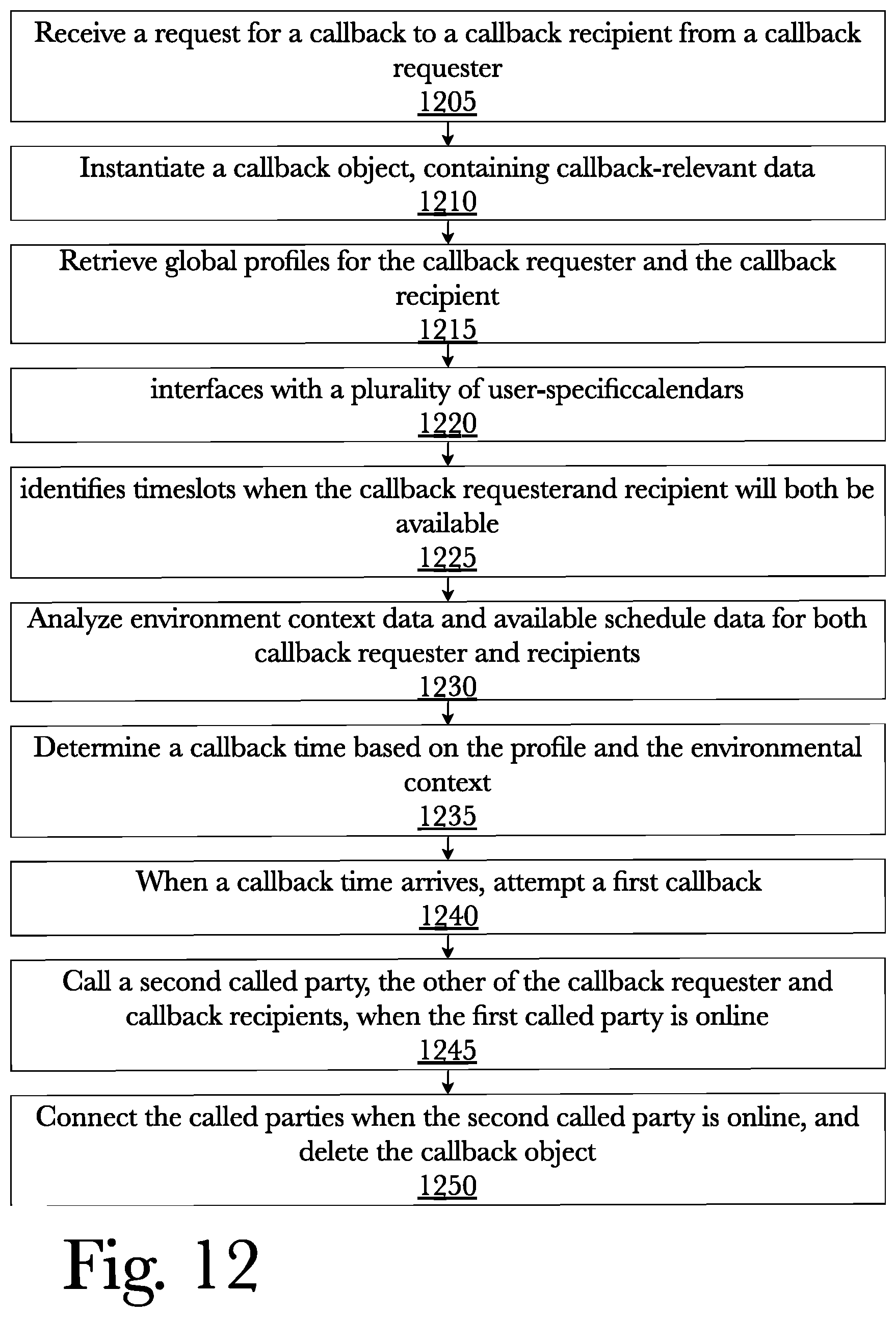
D00013

D00014
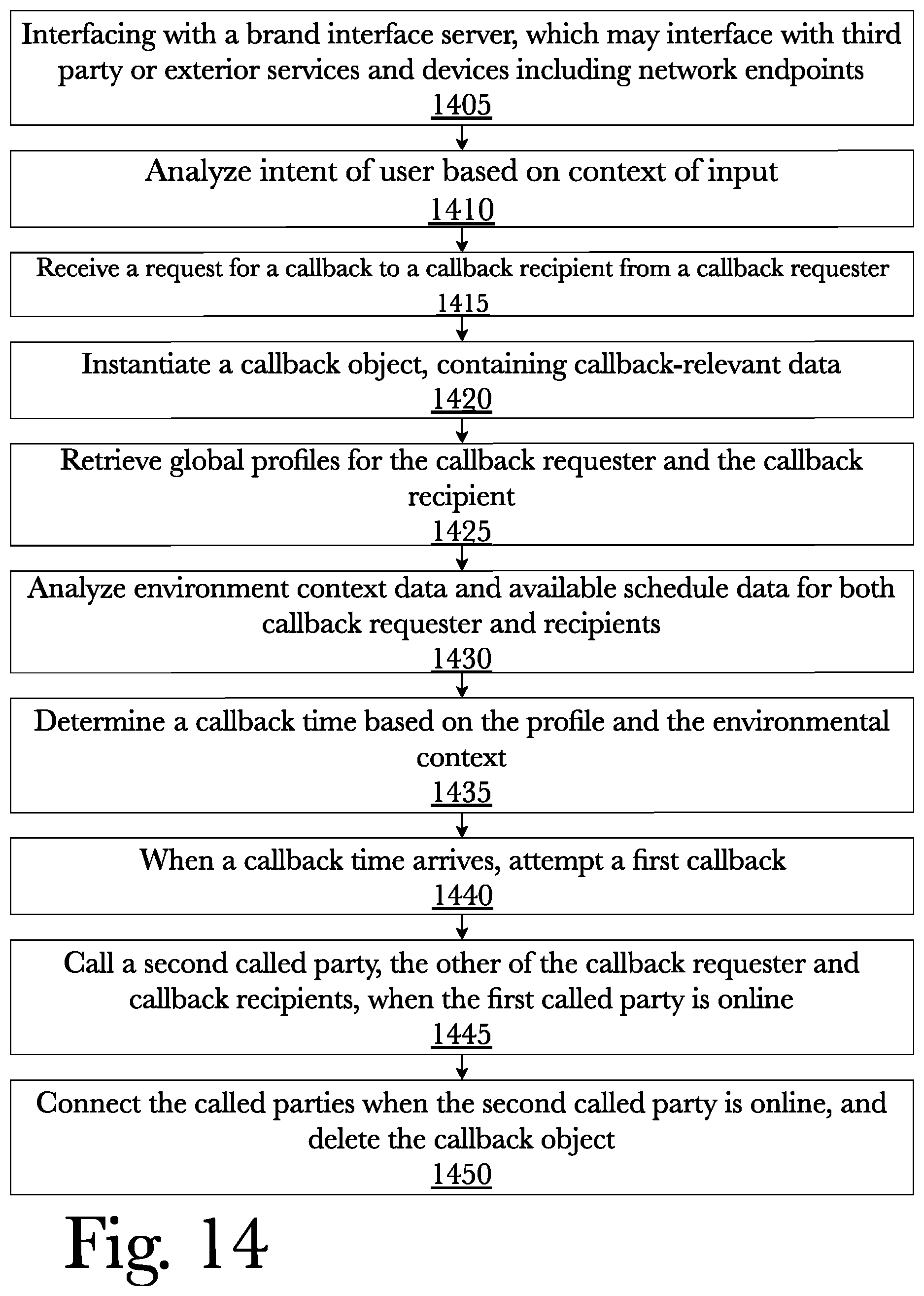
D00015

D00016
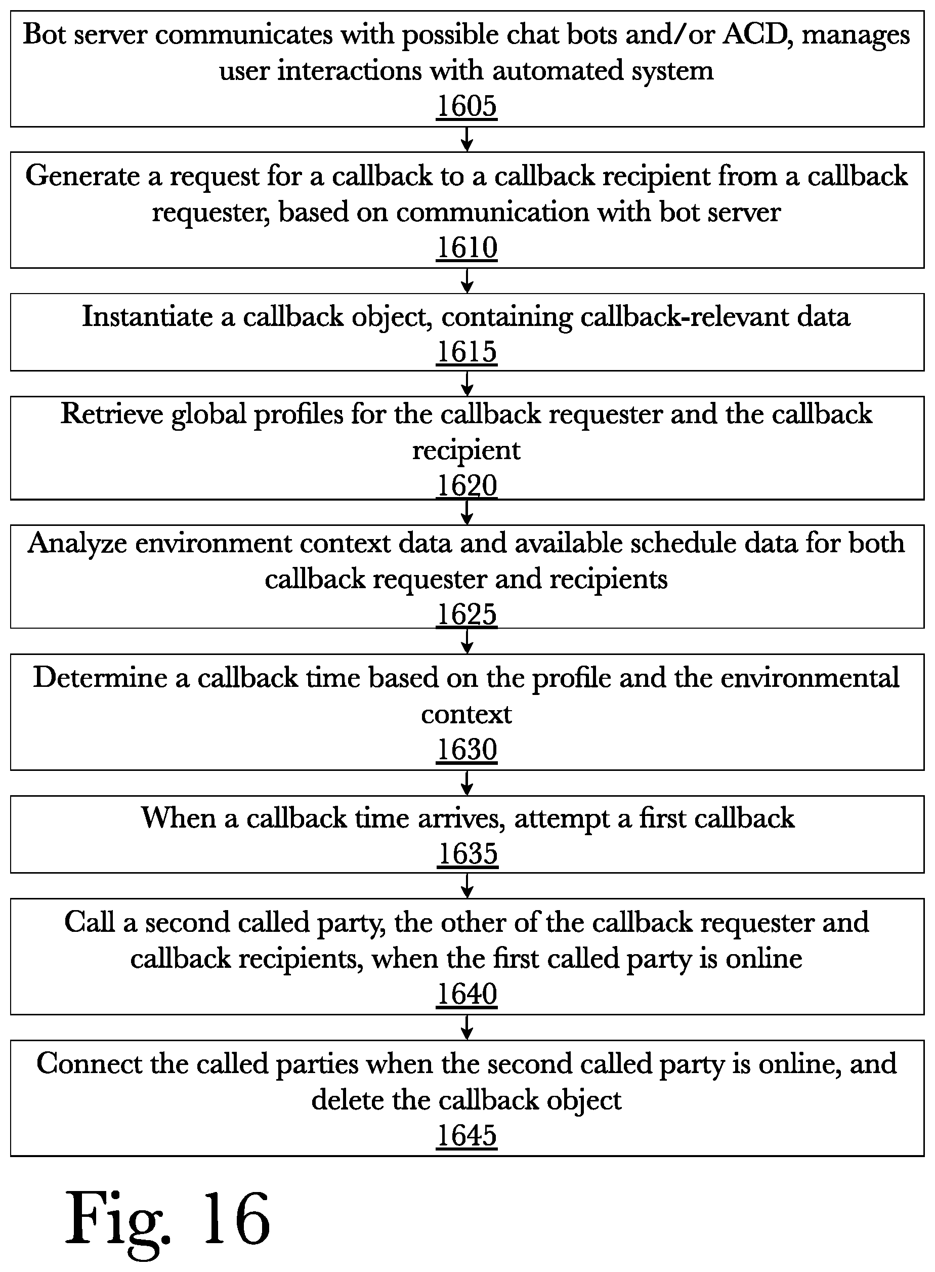
D00017
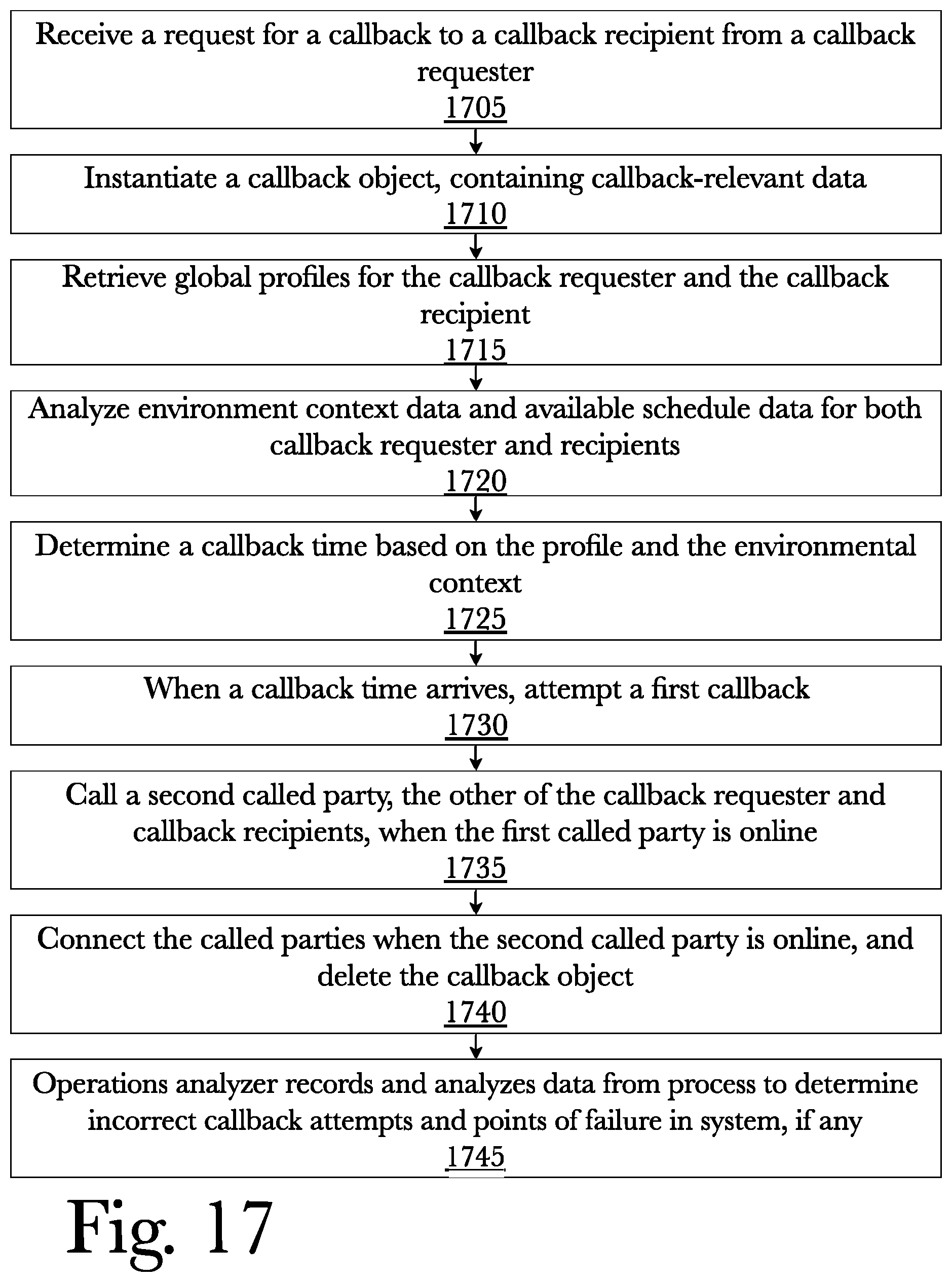
D00018

D00019
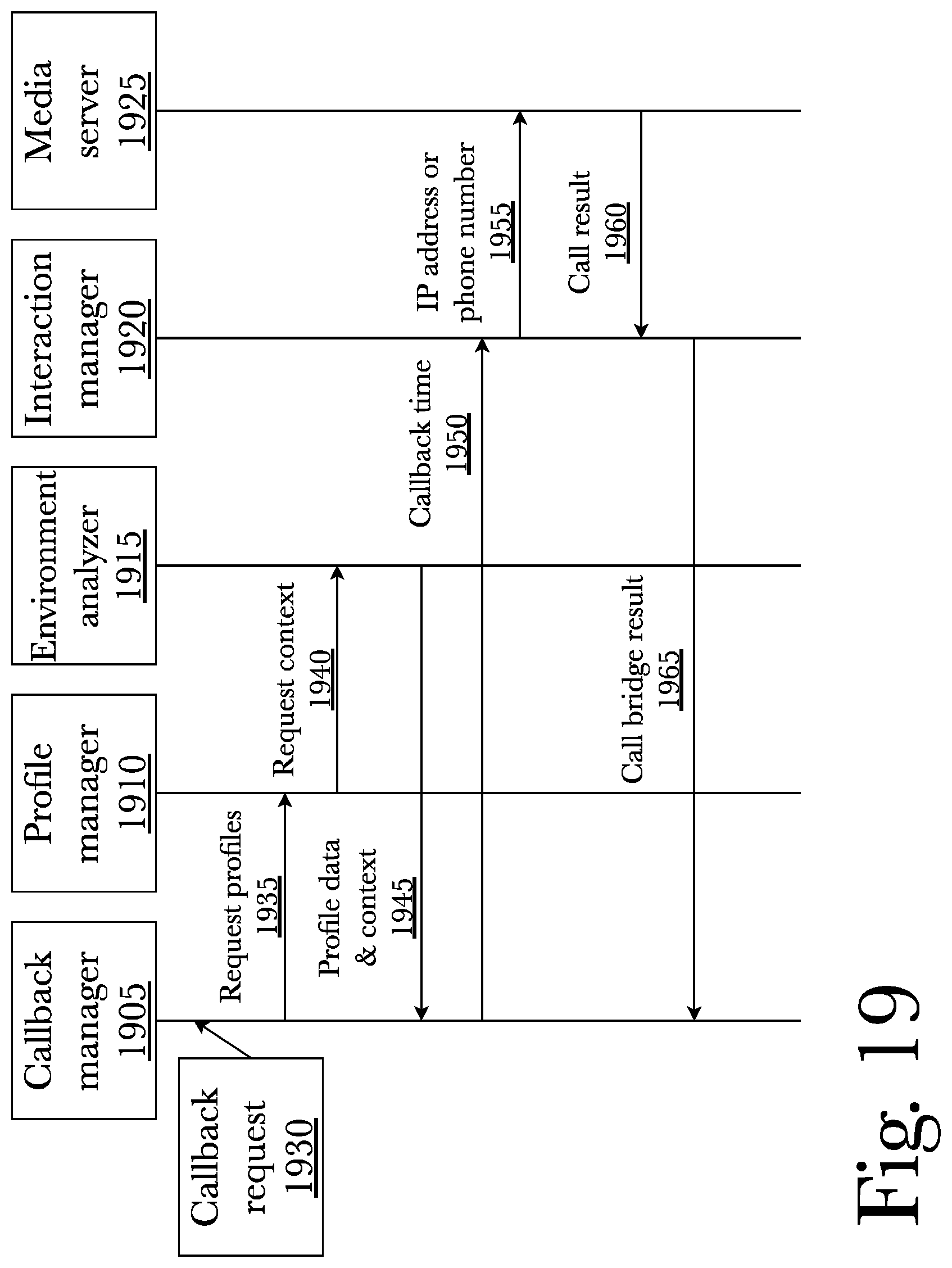
D00020
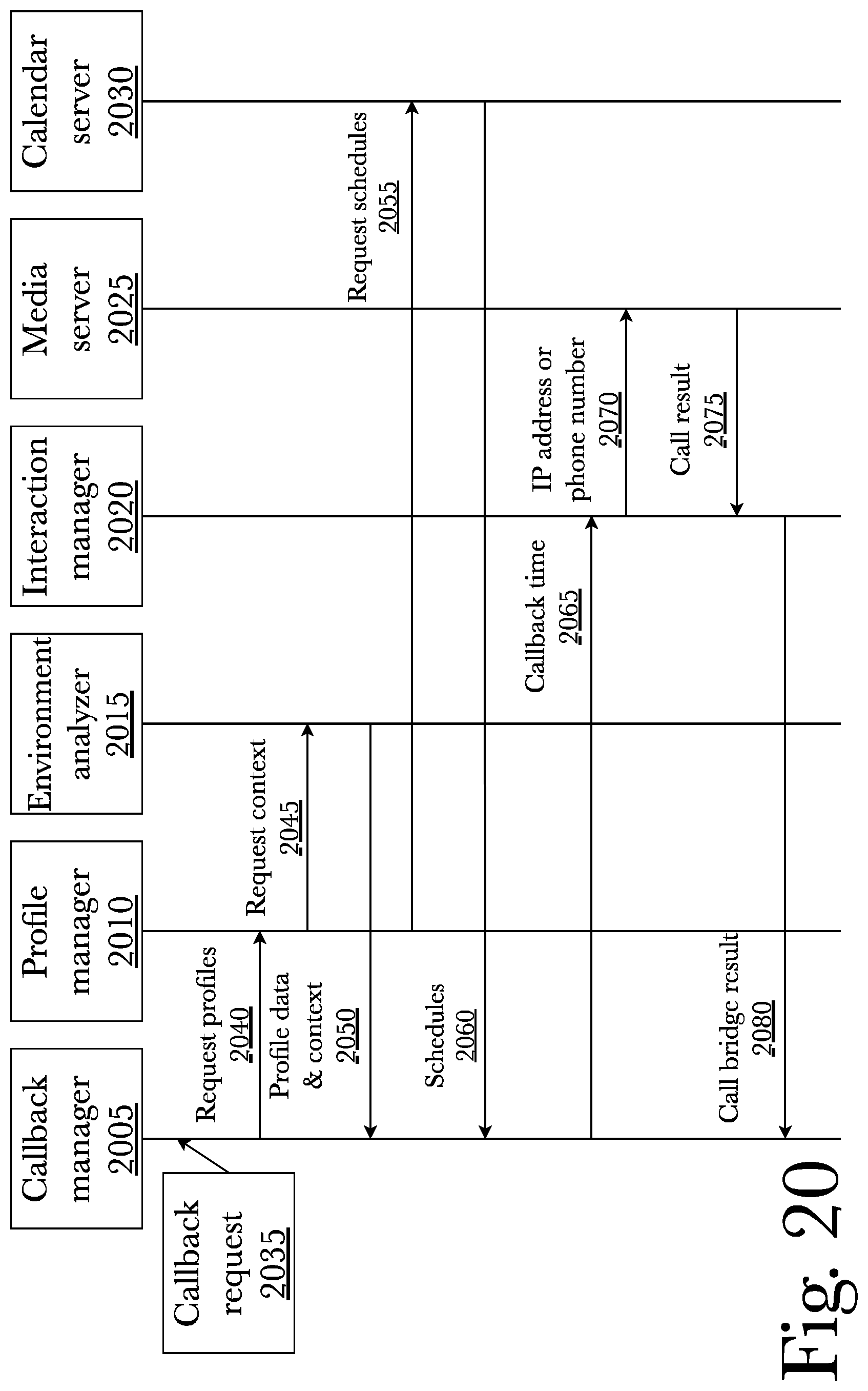
D00021
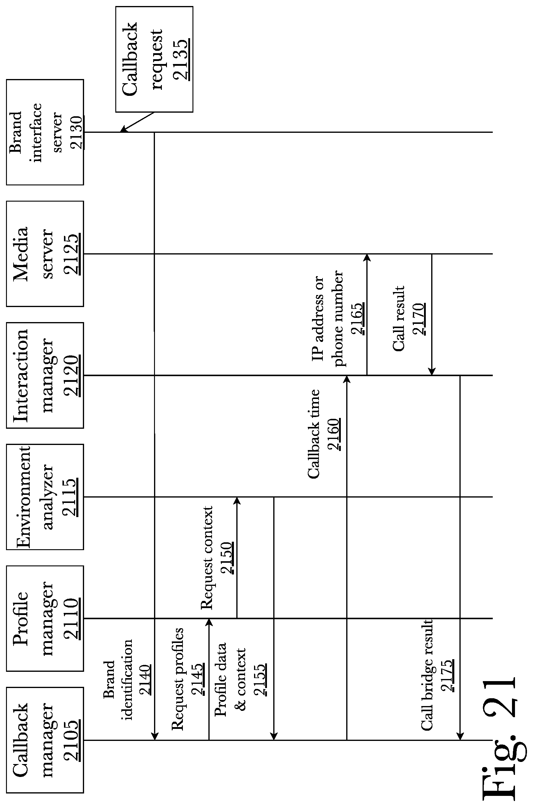
D00022

D00023
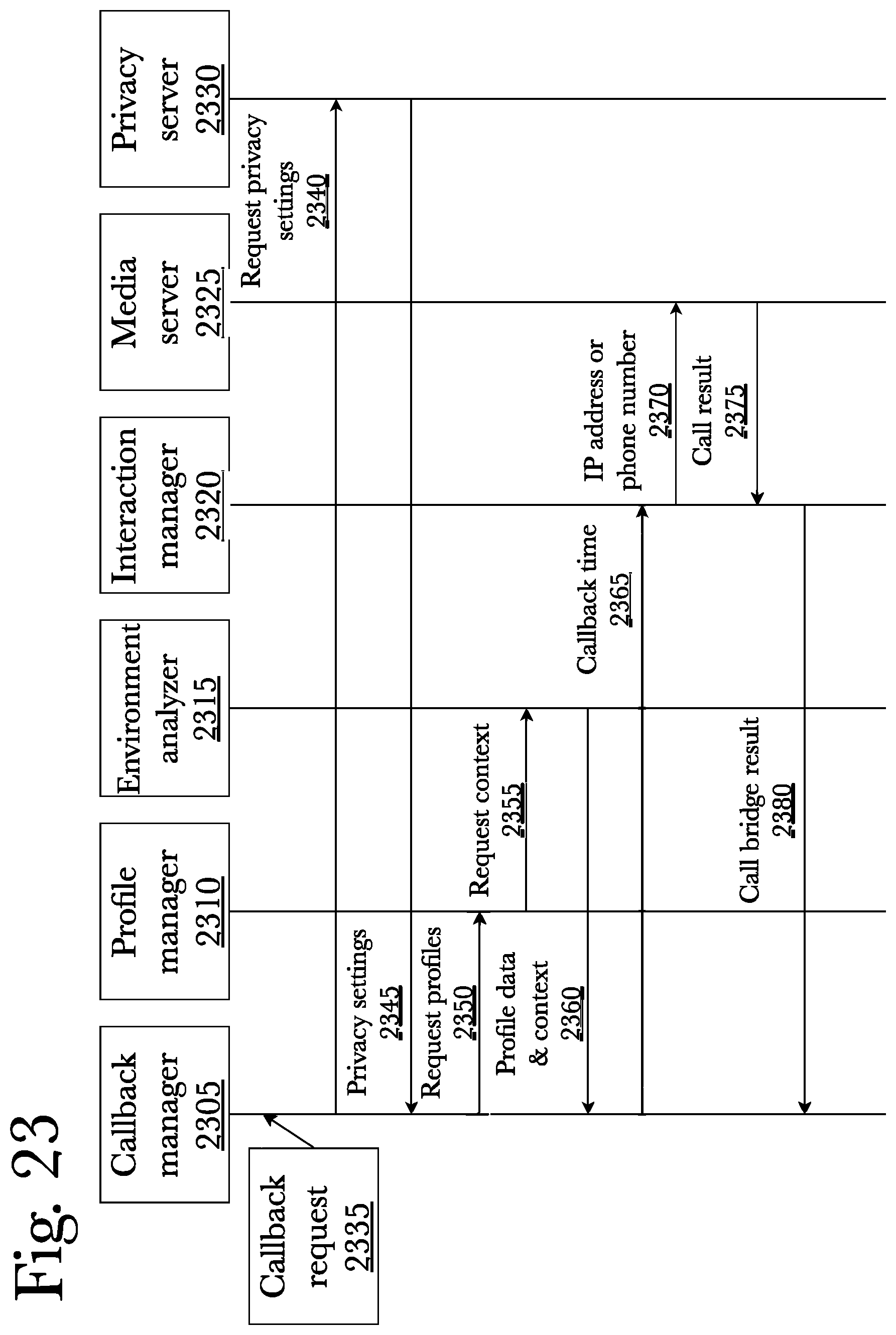
D00024

D00025

D00026
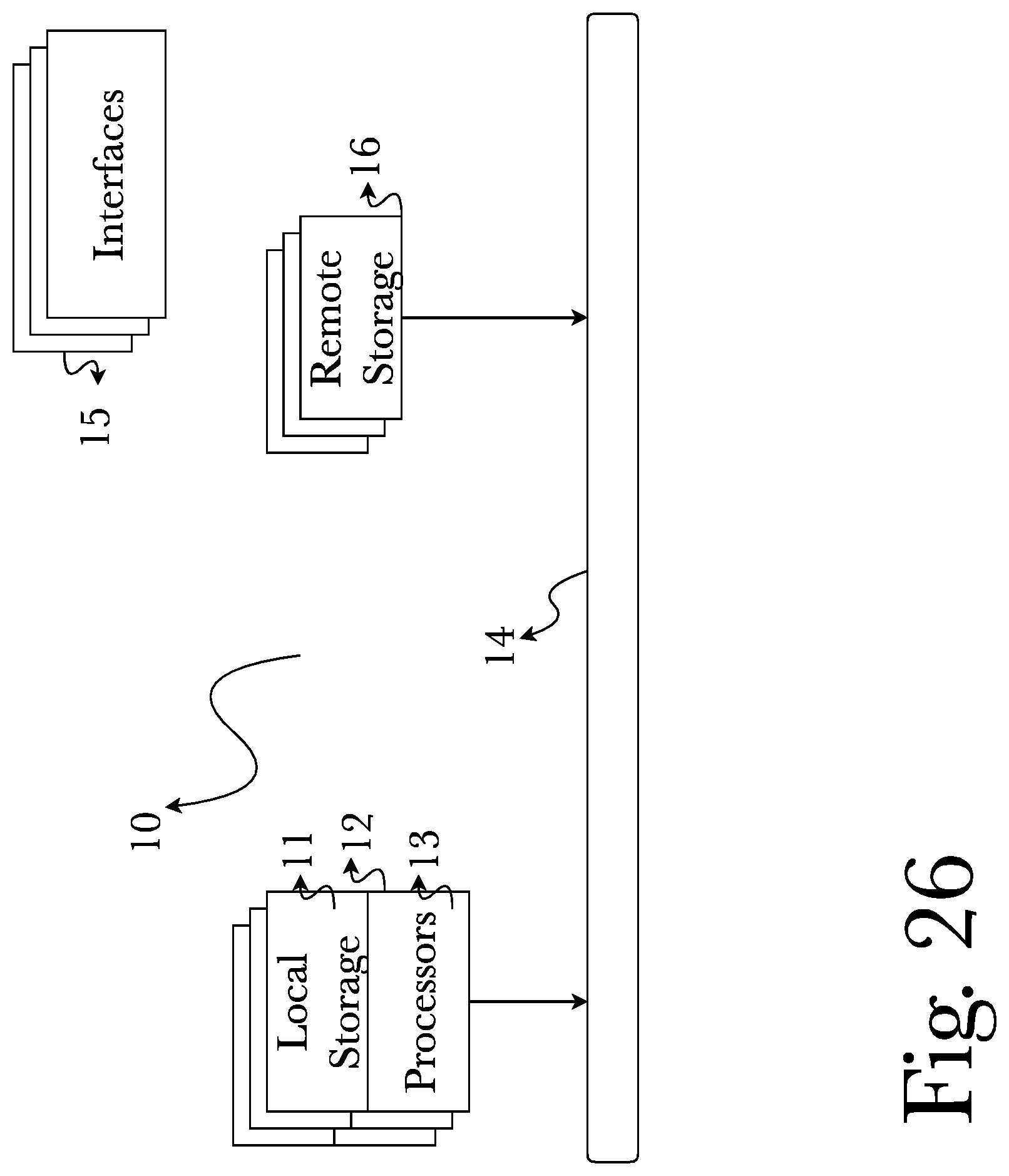
D00027
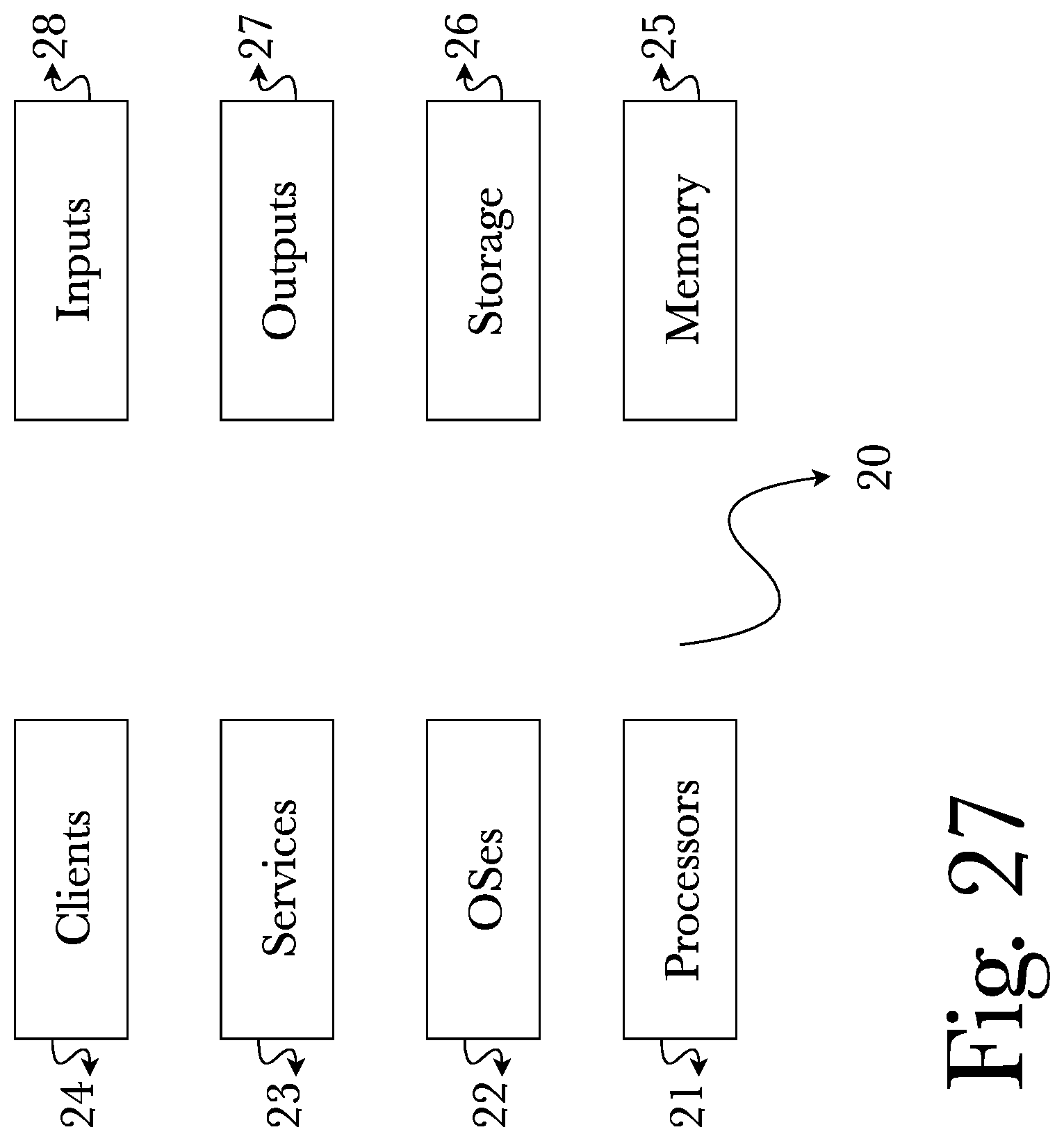
D00028
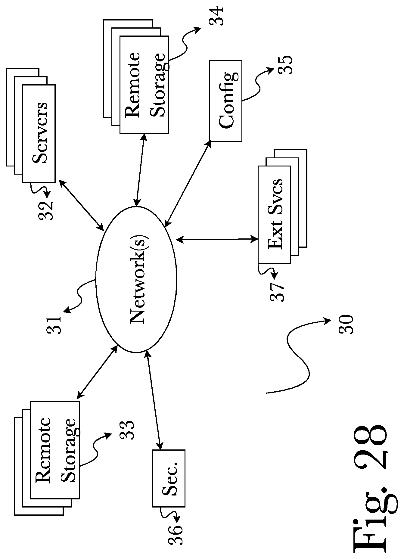
D00029
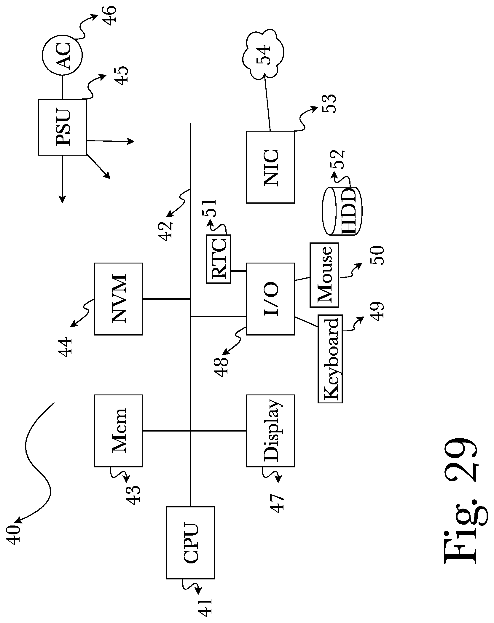
D00030

XML
uspto.report is an independent third-party trademark research tool that is not affiliated, endorsed, or sponsored by the United States Patent and Trademark Office (USPTO) or any other governmental organization. The information provided by uspto.report is based on publicly available data at the time of writing and is intended for informational purposes only.
While we strive to provide accurate and up-to-date information, we do not guarantee the accuracy, completeness, reliability, or suitability of the information displayed on this site. The use of this site is at your own risk. Any reliance you place on such information is therefore strictly at your own risk.
All official trademark data, including owner information, should be verified by visiting the official USPTO website at www.uspto.gov. This site is not intended to replace professional legal advice and should not be used as a substitute for consulting with a legal professional who is knowledgeable about trademark law.