Well treatment operations using diverting system
Gupta , et al. April 27, 2
U.S. patent number 10,988,678 [Application Number 15/922,979] was granted by the patent office on 2021-04-27 for well treatment operations using diverting system. This patent grant is currently assigned to Baker Hughes, a GE company, LLC. The grantee listed for this patent is Baker Hughes, a GE company, LLC. Invention is credited to Dorianne Arlene Castillo, D. V. Satyanarayana Gupta, Anna Jensen, Scott G. Nelson.


View All Diagrams
| United States Patent | 10,988,678 |
| Gupta , et al. | April 27, 2021 |
Well treatment operations using diverting system
Abstract
The flow of a fluid may be diverted from a high permeability zone to a low permeability portion of a subterranean formation by use of particulates comprising dicarboxylic acid, ester or an anhydride of the formula: ##STR00001## or an anhydride thereof, wherein R.sup.1 is --COO--(R.sup.5O)y--R.sup.4 or --H; R.sup.2 and R.sup.3 are selected from the group consisting of --H and --COO--(R.sup.5O)y--R.sup.4, provided both R.sup.2 and R.sup.3 are --COO--(R.sup.5O)y--R.sup.4 when R.sup.1 is --H and further provided only one of R.sup.2 or R.sup.3 is --COO--(R.sup.5O)y--R.sup.4 when R.sup.1 is --COO--(R.sup.5O)y--R.sup.4, R.sup.4 is --H or a C.sub.1-C.sub.6 alkyl group, R.sup.5 is a C.sub.1-C.sub.6 alkylene group, and each y is 0 to 5. The dicarboxylic acid, ester or anhydride may further be admixed with an aliphatic polyester having the general formula of repeating units: ##STR00002## where n is an integer between 75 and 10,000 and R is selected from the group consisting of hydrogen, alkyl, aryl, alkylaryl, acetyl, heteroatoms, and mixtures; thereof.
| Inventors: | Gupta; D. V. Satyanarayana (The Woodlands, TX), Nelson; Scott G. (Cypress, TX), Castillo; Dorianne Arlene (Humble, TX), Jensen; Anna (The Woodlands, TX) | ||||||||||
|---|---|---|---|---|---|---|---|---|---|---|---|
| Applicant: |
|
||||||||||
| Assignee: | Baker Hughes, a GE company, LLC
(Houston, TX) |
||||||||||
| Family ID: | 1000005514193 | ||||||||||
| Appl. No.: | 15/922,979 | ||||||||||
| Filed: | March 16, 2018 |
Prior Publication Data
| Document Identifier | Publication Date | |
|---|---|---|
| US 20180201827 A1 | Jul 19, 2018 | |
Related U.S. Patent Documents
| Application Number | Filing Date | Patent Number | Issue Date | ||
|---|---|---|---|---|---|
| 13928006 | Jun 26, 2013 | 9919966 | |||
| 14461123 | Aug 15, 2014 | 10041327 | |||
| 13928006 | Jun 26, 2013 | 9919966 | |||
| 61664640 | Jun 26, 2012 | ||||
| Current U.S. Class: | 1/1 |
| Current CPC Class: | C09K 8/506 (20130101); E21B 43/04 (20130101); C09K 8/92 (20130101); C09K 8/516 (20130101); E21B 43/26 (20130101); C09K 8/86 (20130101); E21B 33/138 (20130101); C09K 8/74 (20130101); C09K 2208/18 (20130101) |
| Current International Class: | E21B 43/267 (20060101); C09K 8/516 (20060101); C09K 8/508 (20060101); C09K 8/86 (20060101); C09K 8/74 (20060101); E21B 43/26 (20060101); E21B 43/04 (20060101); C09K 8/92 (20060101); C09K 8/506 (20060101); E21B 33/138 (20060101); E21B 43/14 (20060101); C09K 8/536 (20060101) |
References Cited [Referenced By]
U.S. Patent Documents
| 2596843 | May 1952 | Farris |
| 2735269 | February 1956 | Carpenter et al. |
| 2966457 | December 1960 | Starmann et al. |
| 3089542 | May 1963 | Kolodny |
| 3127937 | April 1964 | McGuire, Jr. et al. |
| 3149673 | September 1964 | Pennington |
| 3149674 | September 1964 | Schutze et al. |
| 3151678 | October 1964 | Hanson et al. |
| 3159217 | December 1964 | Hanson |
| 3175615 | March 1965 | East |
| 3249158 | May 1966 | Kieschnick, Jr. et al. |
| 3254717 | June 1966 | Huitt et al. |
| 3266573 | August 1966 | Rixe |
| 3335796 | August 1967 | Parker, Jr. |
| 3335797 | August 1967 | Braunlich, Jr. |
| 3372752 | March 1968 | Prater |
| 3399727 | September 1968 | Graham et al. |
| 3480084 | November 1969 | Eilers |
| 3492147 | January 1970 | Young |
| 3497008 | February 1970 | Graham et al. |
| 3659651 | May 1972 | Graham |
| 3709300 | January 1973 | Pye |
| 3888311 | June 1975 | Cooke |
| 3929191 | December 1975 | Graham et al. |
| 3937283 | February 1976 | Blauer et al. |
| 3954142 | May 1976 | Broaddus et al. |
| 4051900 | October 1977 | Hankins |
| 4074760 | February 1978 | Copeland et al. |
| 4078609 | March 1978 | Pavlich |
| 4078610 | March 1978 | Arnold |
| 4195010 | March 1980 | Russell et al. |
| 4216829 | August 1980 | Murphey |
| 4283089 | August 1981 | Mazza et al. |
| 4421167 | December 1983 | Erbstoesser et al. |
| 4439489 | March 1984 | Johnson |
| 4444264 | April 1984 | Dill |
| 4462466 | July 1984 | Kachnik |
| 4493875 | January 1985 | Beck et al. |
| 4501672 | February 1985 | Connell et al. |
| 4506734 | March 1985 | Nolte |
| 4509598 | April 1985 | Earl et al. |
| 4502967 | May 1985 | Conway |
| 4547468 | October 1985 | Jones et al. |
| 4566539 | January 1986 | Perlman |
| 4585064 | April 1986 | Graham et al. |
| 4632876 | December 1986 | Laird et al. |
| 4654266 | March 1987 | Kachnik |
| 4680230 | July 1987 | Gibb et al. |
| 4717594 | January 1988 | Graham et al. |
| 4733729 | March 1988 | Copeland |
| 4796701 | January 1989 | Hudson et al. |
| 4829100 | May 1989 | Murphey et al. |
| 4830794 | May 1989 | Edgley et al. |
| 4840729 | June 1989 | Levine |
| 4850430 | July 1989 | Copeland et al. |
| 4869960 | September 1989 | Gibb et al. |
| 4875525 | October 1989 | Mana |
| 4887670 | December 1989 | Lord et al. |
| 4888240 | December 1989 | Graham et al. |
| 4895207 | January 1990 | Friedman et al. |
| 4921820 | May 1990 | Rumpf et al. |
| 4921821 | May 1990 | Rumpf et al. |
| 4923714 | May 1990 | Gibb et al. |
| 4969523 | November 1990 | Martin et al. |
| 5014788 | May 1991 | Puri et al. |
| 5069283 | December 1991 | Mack |
| 5074359 | December 1991 | Schmidt |
| 5103905 | April 1992 | Brannon et al. |
| 5163521 | November 1992 | Pustanyk et al. |
| 5175133 | December 1992 | Smith et al. |
| 5240654 | August 1993 | Smith et al. |
| 5246602 | September 1993 | Forrest |
| 5305832 | April 1994 | Gupta et al. |
| 5325921 | July 1994 | Johnson et al. |
| 5330005 | July 1994 | Card et al. |
| 5333689 | August 1994 | Jones et al. |
| 5381864 | January 1995 | Nguyen et al. |
| 5390741 | February 1995 | Payton et al. |
| 5417286 | May 1995 | Palmer et al. |
| 5422183 | June 1995 | Sinclair et al. |
| 5425421 | June 1995 | Coleman et al. |
| 5435391 | July 1995 | Jones et al. |
| 5439055 | August 1995 | Card et al. |
| 5443633 | August 1995 | Hirsbrunner et al. |
| 5492178 | February 1996 | Nguyen |
| 5501273 | March 1996 | Puri |
| 5501275 | March 1996 | Card et al. |
| 5515920 | May 1996 | Luk |
| 5531274 | July 1996 | Bienvenu, Jr. |
| 5547506 | August 1996 | Rae et al. |
| 5551344 | September 1996 | Couet et al. |
| 5582249 | December 1996 | Caveny et al. |
| 5582250 | December 1996 | Constien |
| 5597784 | January 1997 | Sinclair et al. |
| 5604184 | February 1997 | Ellis et al. |
| 5699860 | December 1997 | Grundmann |
| 5799734 | September 1998 | Norman et al. |
| 5837656 | November 1998 | Sinclair |
| 5850875 | December 1998 | McCulloch et al. |
| 5881813 | March 1999 | Brannon et al. |
| 5908073 | June 1999 | Nguyen et al. |
| 5916933 | June 1999 | Johnson et al. |
| 5921317 | July 1999 | Dewprashed et al. |
| 5924488 | July 1999 | Nguyen et al. |
| 5948734 | September 1999 | Sinclair |
| 5950727 | September 1999 | Irani |
| 5955144 | September 1999 | Sinclair et al. |
| 5960878 | October 1999 | Nguyen et al. |
| 5964289 | October 1999 | Hill |
| 5964290 | October 1999 | Riese et al. |
| 5964291 | October 1999 | Bourne et al. |
| 6047772 | April 2000 | Weaver et al. |
| 6059034 | May 2000 | Rickards et al. |
| 6070666 | June 2000 | Montgomery |
| 6079492 | June 2000 | Hoogteejling et al. |
| 6114410 | September 2000 | Betzold |
| 6116342 | September 2000 | Clark et al. |
| 6138760 | October 2000 | Lopez et al. |
| 6169058 | January 2001 | Le et al. |
| 6172011 | January 2001 | Card et al. |
| 6194355 | February 2001 | Jarrett et al. |
| 6209643 | April 2001 | Nguyen et al. |
| 6211120 | April 2001 | Welch et al. |
| 6248838 | June 2001 | Albright |
| 6311773 | November 2001 | Todd et al. |
| 6315041 | November 2001 | Carlisle et al. |
| 6328105 | December 2001 | Betzold |
| 6330916 | December 2001 | Rickards et al. |
| 6348629 | February 2002 | Albright |
| 6364018 | April 2002 | Brannon et al. |
| 6367548 | April 2002 | Purvis et al. |
| 6372678 | April 2002 | Youngman et al. |
| 6399546 | June 2002 | Chang et al. |
| 6406789 | June 2002 | McDaniel et al. |
| 6412559 | July 2002 | Gunter et al. |
| 6439309 | August 2002 | Matherly et al. |
| 6439310 | August 2002 | Scott, III et al. |
| 6451953 | September 2002 | Albright |
| 6491099 | December 2002 | Di Lullo Arias et al. |
| 6503676 | January 2003 | Yamashita et al. |
| 6508305 | January 2003 | Brannon et al. |
| 6528157 | March 2003 | McDaniel et al. |
| 6541579 | April 2003 | Albright |
| 6579947 | June 2003 | Heitz et al. |
| 6582819 | June 2003 | McDaniel et al. |
| 6632527 | October 2003 | McDaniel et al. |
| 6640897 | November 2003 | Misselbrook et al. |
| 6667261 | December 2003 | Anshits et al. |
| 6705400 | March 2004 | Nguyen et al. |
| 6725931 | April 2004 | Nguyen et al. |
| 6742590 | June 2004 | Nguyen |
| 6749025 | June 2004 | Brannon et al. |
| 6766817 | July 2004 | da Silva |
| 6776235 | July 2004 | England |
| 6772838 | August 2004 | Dawson et al. |
| 6830105 | December 2004 | Theising et al. |
| 6892813 | April 2005 | Nguyen et al. |
| 7001872 | February 2006 | Pyecroft et al. |
| 7036590 | May 2006 | Harris |
| 7036591 | May 2006 | Canan et al. |
| 7036597 | May 2006 | O'Brien et al. |
| 7044220 | May 2006 | Nguyen et al. |
| 7066258 | June 2006 | Justus et al. |
| 7086460 | August 2006 | Nguyen et al. |
| 7153575 | December 2006 | Anderson et al. |
| 7207386 | April 2007 | Brannon et al. |
| 7210528 | May 2007 | Brannon et al. |
| 7213651 | May 2007 | Brannon et al. |
| 7226971 | June 2007 | Ramesh et al. |
| 7270879 | September 2007 | McCrary |
| 7271133 | September 2007 | Weaver et al. |
| 7275596 | October 2007 | Willberg et al. |
| 7303018 | December 2007 | Cawiezel et al. |
| 7350572 | April 2008 | Fredd et al. |
| 7361693 | April 2008 | Albright et al. |
| 7426961 | September 2008 | Stephenson et al. |
| 7472751 | January 2009 | Brannon et al. |
| 7510009 | March 2009 | Cawiezel et al. |
| 7565929 | July 2009 | Bustos |
| 7603896 | October 2009 | Kalfayan et al. |
| 7638468 | December 2009 | Gupta |
| 7669655 | March 2010 | Brannon |
| 7726399 | June 2010 | Brannon et al. |
| 7913762 | March 2011 | Wheeler et al. |
| 7918277 | April 2011 | Brannon et al. |
| 7971643 | July 2011 | Brannon et al. |
| 8061424 | November 2011 | Willberg et al. |
| 8127850 | March 2012 | Brannon et al. |
| 8173581 | May 2012 | Huang |
| 8205675 | June 2012 | Brannon et al. |
| 8408305 | April 2013 | Brannon et al. |
| 8739878 | June 2014 | Brannon et al. |
| 8757260 | June 2014 | Luo et al. |
| 8789596 | July 2014 | Curtis et al. |
| 8936085 | January 2015 | Boney et al. |
| 9919966 | March 2018 | Gupta |
| 9920607 | March 2018 | Brannon |
| 9920610 | March 2018 | Nelson |
| 9920614 | March 2018 | Trinh |
| 9938811 | April 2018 | Bestaoui-Spurr |
| 2002/0023752 | February 2002 | Qu et al. |
| 2002/0048676 | April 2002 | McDaniel et al. |
| 2003/0050432 | March 2003 | Ramesh et al. |
| 2003/0102128 | June 2003 | Dawson et al. |
| 2003/0224165 | December 2003 | Anderson et al. |
| 2003/0234106 | December 2003 | Surjaatmadja |
| 2004/0023812 | February 2004 | England et al. |
| 2004/0023818 | February 2004 | Nguyen et al. |
| 2004/0040708 | March 2004 | Stephenson et al. |
| 2004/0072700 | April 2004 | Gupta et al. |
| 2004/0224165 | December 2004 | Barron et al. |
| 2004/0244978 | December 2004 | Shaarpour |
| 2004/0261996 | December 2004 | Munoz et al. |
| 2005/0016732 | January 2005 | Brannon et al. |
| 2005/0019574 | January 2005 | McCrary |
| 2005/0028976 | February 2005 | Nguyen et al. |
| 2005/0028979 | February 2005 | Brannon et al. |
| 2005/0034860 | February 2005 | Lauritzen |
| 2005/0059558 | March 2005 | Blauch et al. |
| 2005/0089631 | April 2005 | Nguyen et al. |
| 2005/0130848 | June 2005 | Todd et al. |
| 2005/0137095 | June 2005 | Cawiezel et al. |
| 2005/0244641 | November 2005 | Vincent |
| 2005/0272612 | December 2005 | Dawson et al. |
| 2005/0274523 | December 2005 | Wood et al. |
| 2006/0011342 | January 2006 | Lizak |
| 2006/0042797 | March 2006 | Fredd et al. |
| 2006/0073980 | April 2006 | Brannon et al. |
| 2006/0151169 | July 2006 | Ortiz et al. |
| 2006/0185848 | August 2006 | Surjaatmadja et al. |
| 2006/0196659 | September 2006 | Jee et al. |
| 2006/0283591 | December 2006 | Willberg et al. |
| 2008/0093073 | April 2008 | Bustos et al. |
| 2008/0139416 | June 2008 | Rimassa et al. |
| 2008/0156531 | July 2008 | Boone et al. |
| 2008/0179057 | July 2008 | Dawson |
| 2010/0089648 | April 2010 | Hall et al. |
| 2010/0200235 | August 2010 | Luo et al. |
| 2010/0252325 | October 2010 | Porche |
| 2010/0263866 | October 2010 | Huang et al. |
| 2011/0088905 | April 2011 | Kabishcher et al. |
| 2011/0180259 | July 2011 | Willberg et al. |
| 2012/0024530 | February 2012 | Todd et al. |
| 2012/0073809 | March 2012 | Clum et al. |
| 2012/0085536 | April 2012 | Alboudwarej et al. |
| 2012/0142562 | June 2012 | Spindler et al. |
| 2012/0267102 | October 2012 | Huang et al. |
| 2012/0285692 | November 2012 | Potapenko |
| 2013/0168096 | July 2013 | Parkhonyuk et al. |
| 2013/0341025 | December 2013 | Gupta |
| 2013/0341030 | December 2013 | Brannon et al. |
| 2014/0014338 | January 2014 | Crews et al. |
| 2014/0138087 | May 2014 | Gupta |
| 2014/0178325 | June 2014 | Martinez-Castro et al. |
| 2014/0299318 | October 2014 | Crews et al. |
| 2014/0318783 | October 2014 | Martin et al. |
| 2014/0352959 | December 2014 | Nelson et al. |
| 2015/0041132 | February 2015 | Nelson et al. |
| 2015/0047838 | February 2015 | Lecerf |
| 2015/0129214 | May 2015 | Boney et al. |
| 2015/0233226 | August 2015 | Holzhauser |
| 2015/0330197 | November 2015 | Brannon et al. |
| 2017/0051599 | February 2017 | Bestaoui-Spurr et al. |
| 2017/0159402 | June 2017 | Nelson et al. |
| 2329834 | Jun 2002 | CA | |||
| 0308257 | Sep 1989 | EP | |||
| 0773343 | May 1997 | EP | |||
| 1023382 | Aug 2006 | EP | |||
| 2137262 | Oct 1984 | GB | |||
| 2319796 | Jun 1998 | GB | |||
| 01/66908 | Sep 2001 | WO | |||
| 0005302 | Feb 2002 | WO | |||
| 02/26656 | Apr 2002 | WO | |||
| 2004018840 | Mar 2004 | WO | |||
| 2004/083600 | Sep 2004 | WO | |||
| 2007032956 | Mar 2007 | WO | |||
| 2010027839 | Mar 2010 | WO | |||
| 2011018257 | Feb 2011 | WO | |||
Other References
|
Allison, Dave; "Accessfrac Service Diversion Technology"; HO9034; Jan. 30, 2011; 45 pages; Haliburton Energy Services. cited by applicant . Allison, D., Method to Help Improve Long-Term Production Following Shale Fracture Treatments, H09032; Oct. 31, 2011; Halliburton Energy Services (23 pages). cited by applicant . BJ Services Company, "LiteProp 125 Lightweight Proppant," Nov. 21, 2003, USA. cited by applicant . Barree, B., "Pre-Frac Injection Tests in Tight Gas Reservoirs" Presentation, Apr. 17, 2003, Barree & Associates, Lakewood, Colorado (33 pages). cited by applicant . Chang, F., et al., "Chemical Diversion Techniques Used for Carbonate Matrix Acidizing: An Overview and Case Histories",2007 SPE International Symposium on Oilfield Chemistry; SPE 106444; Feb. 28-Mar. 2, 2007; Houston, Texas. cited by applicant . Chellappah, et al., "A New Outlook on the Ideal Packing Theory for Bridging Solids", Society of Petroleum Engineers, SPE 151636, Feb. 16-17, 2012. cited by applicant . Drilling Formulas.com reference sheet, "Bottom-hole pressure calculation", pp. 1-2 (Jan. 2010). cited by applicant . Glasbergen, et al., "Design and Field Testing of Truly Novel Diverting Agent", Society of Petroleum Engineers, SPE 102606, Sep. 24-27, 2006. cited by applicant . Gupta, et al., "The History and Success of Liquid CO2 and CO2/N2 Fracturing System"; SPE 40016, Society of Petroleum Engineers, Inc. (1998). cited by applicant . Halliburton; "AccessFrac Stimulation Service: Enhanced Proppant Distribution Provides Improved Access to Complex Fracture Networks in Shale Formations"; HO8720; Nov. 2011; 2 pages; Haliburton Production Enhancement. cited by applicant . Halliburton, "Halliburton Introduces AccessFrac Service"; Product Announcement, Oct. 2011, Halliburton (2 pages). cited by applicant . Hannah, R.R., et al., "The Real-Time Calculation of Accurate Bottomhole Fracturing Pressure from Surface Measurements Using Measured Pressures as a Base", SPE 12062, Dallas, TX, Oct. 5-8, 1983 (pp. 1-2). cited by applicant . International Search Report and Written Opinion, PCT Application No. PCT/US2012/035202 dated Nov. 29, 2012. cited by applicant . International Search Report and Written Opinion, PCT Application No. PCT/US2017/042397 dated Oct. 20, 2017. cited by applicant . Kaageson-Loe, et al., "Particulate-Based Loss-Prevention Material-The secrets of Fracture Sealing REvealed", Society of Petroleum Engineers, SPE 112595, Dec. 2009. cited by applicant . Nitters, et al., "Granular Diverting Agents Selection, Design and Performance", SPE 18884 (1989). cited by applicant . Pessier, R.C., et al., "Quantifying Common Drilling Problems with Mechanical Specific Energy and a Bit-Specific Coefficient of Sliding Friction," SPE 24584; 67th Annual Technical Conference and Exhibition of the Society of Petroleum engineers, Washington, D.C., Oct. 4-7, 1992, pp. 373-388. cited by applicant . Reddy, et al., "Activator Development for Controlling Degradation Rates of Polymeric Diverting Agents", Society of Petroleum Engineers, SPE 164117, Feb. 2014. cited by applicant . Savari, et al., "Engineered LCM Design Yields Novel Activating Material for Potential Application in Severe Lost Circulation Scenarios", Society of Petroleum Engineers, SPE 164748, Apr. 15-17, 2013. cited by applicant . Savari, et al., "Improved Lost Circulation Treatment Design and Testing Techniques Minimize Formation Damage", SPE 143603, The Netherlands, Jun. 7-10, 2011. cited by applicant . Solares, et al., "Successful Application of Innovative Fiber-Diverting Technology Achieved Effective Diversion in Acid Stimulation Treatments in Saudi Arabia Deep Gas Producers", Society of Petroleum Engineers, SPE 115528, Oct. 20-22, 2008. cited by applicant . Spectra Chemical Catalog, 2013, pp. 1-46. cited by applicant . Wood, et al., "Ultra-Lightweight Proppant Development Yields Exciting New opportunities in Hydraulic Fracturing Design"; SEP84309; Society of Petroleum Engineers, Inc. (2003). cited by applicant . Notice of Allowance in U.S. Appl. No. 15/234,314, filed Aug. 11, 2016, entitled "Method fo Fracking Using Silicone Surfactants", (5 pages). cited by applicant. |
Primary Examiner: Nold; Charles R
Attorney, Agent or Firm: Jones; John Wilson Jones Delflache LLP
Parent Case Text
This application is a continuation-in-part application of U.S. patent application Ser. No. 13/928,006, filed on Jun. 26, 2013 (which claims the benefit of U.S. patent application Ser. No. 61/664,640, filed on Jun. 26, 2012) and is a continuation-in-part application of U.S. patent application Ser. No. 14/461,123, filed on Aug. 15, 2014 (which further is a continuation-in-part of U.S. patent application Ser. No. 13/928,006, claiming the benefit of U.S. patent application Ser. No. 61/664,640), all of which are herein incorporated by reference.
Claims
What is claimed is:
1. A method of stimulating a subterranean formation penetrated by a well comprising: (A) introducing into the well a fluid comprising particulates of (i) or both (i) and (ii), wherein (i) is a compound of formula (I): ##STR00008## or an anhydride thereof and (ii) is at least one aliphatic polyester having repeating units (II): ##STR00009## wherein: R.sup.1 is --COO--(R.sup.5O)y--R.sup.4 or --H; R.sup.2 and R.sup.3 are selected from the group consisting of --H and --COO--(R.sup.5O)y--R.sup.4; provided both R.sup.2 and R.sup.3 are --COO--(R.sup.5O)y--R.sup.4 when R.sup.1 is --H and further provided only one of R.sup.2 or R.sup.3 is --COO--(R.sup.5O)y--R.sup.4 when R.sup.1 is --COO--(R.sup.5O)y--R.sup.4; R.sup.4 is --H or a C.sub.1-C.sub.6 alkyl group; R.sup.5 is a C.sub.1-C.sub.6 alkylene group; each y is 0 to 5; n is an integer between 75 and 10,000; and R is selected from the group consisting of hydrogen, alkyl, aryl, alkylaryl, acetyl, heteroatoms and mixtures thereof; the particulates having a sized distribution to form bridging solids on a face of a first permeability zone of the formation and block the penetration of the fluid into the first permeability zone of the formation; (B) forming a filter cake consisting essentially of the particulates on the face of the first permeability zone and increasing resistance to flow of the well treatment fluid through the first permeability zone by a pressure drop through the filter cake; and (C) diverting flow of the fluid to a second zone of the formation, the second zone having a permeability lower than the permeability of the first permeability zone.
2. The method of claim 1, wherein R.sup.1 is --COO--(R.sup.5O)y--R.sup.4 and R.sup.2 is --H.
3. The method of claim 2, wherein y is 0 and R.sup.4 is --H.
4. The method of claim 1, wherein R.sup.1 is --H and wherein R.sup.2 and R.sup.3 are --COO--(R.sup.5O)y--R.sup.4.
5. The method of claim 4, wherein y is 0 and R.sup.4 is --H.
6. The method of claim 4, wherein at least some of the particulates are selected from the group consisting of phthalic acid, phthalic acid anhydride and mixtures thereof.
7. The method of claim 1, wherein the fluid is an acidizing fluid having from about 70 to about 99 volume percent of aqueous acid and further wherein the strength of the acid is greater than or equal to 10%.
8. The method of claim 1, wherein the fluid is a wellbore completion fluid or a fluid loss pill.
9. The method of claim 1, wherein the amount of compound of formula (I) in the fluid is from about 0.01 to about 30 volume percent.
10. The method of claim 1, wherein at least 60% of the particulates in the fluid have a particle size between from about 150 .mu.m to about 2000 .mu.m.
11. The method of claim 1, wherein the particulates have a particle size between from about 150 .mu.m to about 2000 .mu.m.
12. The method of claim 1, wherein the fluid comprises particles comprising a material selected from the group consisting of dextran, cellulose, chitin, chitosan, protein, an orthoester, poly(glycolide), poly(c-caprolactone), poly(hydroxybutyrate); aliphatic polycarbonates; poly(amino acids); poly(ethylene oxide); and polyphosphazenes.
13. The method of claim 1, wherein the fluid is a hydraulic fracturing fluid.
14. A method of stimulating a subterranean formation penetrated by a well comprising: (A) pumping into a first permeability zone a fluid comprising particulates of (i) or both (i) and (ii), wherein (i) is a compound of formula (I): ##STR00010## or an anhydride thereof and (ii) is at least one aliphatic polyester having repeating units (II): ##STR00011## wherein: R.sup.1 is --COO--(R.sup.5O)y--R.sup.4 or --H; R.sup.2 and R.sup.3 are selected from the group consisting of --H and --COO--(R.sup.5O)y--R.sup.4; provided both R.sup.2 and R.sup.3 are --COO--(R.sup.5O)y--R.sup.4 when R.sup.1 is --H and further provided only one of R.sup.2 or R.sup.3 is --COO--(R.sup.5O)y--R.sup.4 when R.sup.1 is --COO--(R.sup.5O)y--R.sup.4; R.sup.4 is --H or a C.sub.1-C.sub.6 alkyl group; R.sup.5 is a C.sub.1-C.sub.6 alkylene group; each y is 0 to 5; n is an integer between 75 and 10,000 and R is selected from the group consisting of hydrogen, alkyl, aryl, alkylaryl, acetyl, heteroatoms and mixtures thereof; and forming a temporary plug or viscous pill in the first permeability zone and increasing pressure in the first permeability zone upon the formation of the temporary plug or viscous pill; (B) diverting flow of fluid introduced into the well after the formation of the temporary plug or viscous pill (A) into a second permeability zone wherein permeability of the first permeability zone is greater than permeability of the second permeability zone.
15. The method of claim 14, wherein at least some of the particulates are selected from the group consisting of isophthalic acid, isophthalic acid anhydride, terephthalic acid, or terephthalic acid anhydride and mixtures thereof.
16. The method of claim 14, wherein at least 60% of the particulates have a particle size between from about 150 .mu.m to about 2000 .mu.m.
17. A method of stimulating a subterranean formation penetrated by a well with a diverting agent, the method comprising: (A) introducing into the well a fluid comprising particulates of (i) or both (i) and (ii) wherein (i) is a compound of formula (I): ##STR00012## or an anhydride thereof and (ii) is at least one aliphatic polyester having repeating units (II): ##STR00013## wherein: R.sup.1 is --COO--(R.sup.5O)y--R.sup.4 or --H; R.sup.2 and R.sup.3 are selected from the group consisting of --H and --COO--(R.sup.5O)y--R.sup.4; provided both R.sup.2 and R.sup.3 are --COO--(R.sup.5O)y--R.sup.4 when R.sup.1 is --H and further provided only one of R.sup.2 or R.sup.3 is --COO--(R.sup.5O)y--R.sup.4 when R.sup.1 is --COO--(R.sup.5O)y--R.sup.4; R.sup.4 is --H or a C.sub.1-C.sub.6 alkyl group; R.sup.5 is a C.sub.1-C.sub.6 alkylene group; each y is 0 to 5; n is an integer between 75 and 10,000; and R is selected from the group consisting of hydrogen, alkyl, aryl, alkylaryl, acetyl, heteroatoms and mixtures thereof; (B) forming a filter cake consisting of the particulates in a first permeable zone; (C) creating a pressure drop through the filter cake and increasing resistance to fluid flow through the first permeable zone; and (D) diverting flow of fluid to a second zone of the formation, the second zone having a permeability lower than the permeability of the first permeability zone.
18. The method of claim 17, wherein R.sup.1 is --H and R.sup.3 is --COO--(R.sup.5O)y--R.sup.4.
19. The method of claim 17, wherein the particulates of formula (I) are selected from the group consisting of phthalic acid, phthalic acid anhydride, isophthalic acid, isophthalic acid anhydride, terephthalic acid and terephthalic acid anhydride and mixtures thereof.
20. The method of claim 17, wherein at least 60% of the particulates have a particle size between from about 150 .mu.m to about 2000 .mu.m.
Description
FIELD OF THE DISCLOSURE
The disclosure relates to methods of re-directing well treatment fluids from high permeability zones of a subterranean formation to low permeability zones with aromatic dicarboxylic acids, esters and anhydrides, optionally admixed with aliphatic polyesters.
BACKGROUND OF THE DISCLOSURE
The success of well treatment operations often depends on optimizing placement of fluids downhole. This is especially the case for fluids used in acid stimulation, hydraulic fracturing, sand control, well clean-out and well completion operations. It further is true for treatment operations which employ fluid loss pills.
In the past, much interest has focused on methods for improving downhole placement of well treatment fluids used in acid stimulation and hydraulic fracturing operations. Acid simulation of a hydrocarbon producing formation, such as by matrix acidizing, enhances the production of hydrocarbons. In this procedure, acid or an acid-forming material is injected into the formation and the acid reacts with minerals in the formation. As a result, near-wellbore permeability is improved by the opening of channels or wormholes within the formation. In addition to dissolving formation materials, the acid may remove blockages caused by natural or man-made conditions. The procedure is especially prevalent in the treatment of carbonate formations since the reaction products are soluble in the spent acid.
Early attempts at optimizing the placement of acid downhole focused on injection of a simple acidic solution into the wellbore. Such attempts proved to be inefficient as the fluid often reacted or was spent too quickly. Such treatment fluids were therefore incapable of penetrating deep into the formation, thereby limiting their effectiveness to very near-wellbore applications. Thus, where the treated subterranean formation contained sections with varying permeability, the injected acid typically acidized the zone within the formation which had the highest permeability and the highest degree of water saturation. A permeability contrast between areas of high permeability (treated areas) within the formation and areas of low permeability (untreated areas) resulted.
It is necessary that acid placement downhole be optimized to provide uniform distribution of treatment fluid over the zone being treated. Chemical, as well as mechanical, methods have been developed to divert the flow of treatment fluids from the higher permeability and/or water saturated sections of the formation to the lower permeability or oil bearing sections. The difference between chemical and mechanical diversion is that chemical diverting agents achieve diversion by increasing flow resistance inside the created channels, whereas mechanical diversion controls the fluid entry point at the wellbore. Hence chemical diverting agents are often considered to be internal diverting agents compared to external mechanical diversion.
In the past, chemical diversion has been achieved using viscous fluids, foams and gels which reportedly improve acid placement. Though several chemical diverters have emerged over the years, they have each failed to precisely control the flow of the acidizing fluid. One such alternative, disclosed in U.S. Pat. No. 7,060,661 is drawn to the use of a single surfactant system as a gelled acidizing fluid wherein the surfactant gels an acid fluid containing between 3 to 15% HCl solution by volume. Extra energy is often required to pump this already viscous gelled fluid into the well.
Further, N,N,-bis (2-hydroxyethyl) tallow ammonium acetate has been proposed as a gelling agent though the compound exhibits breakdown at higher temperatures as the acid is spent. In addition, since the compound gels too quickly, it is unable to fully penetrate into the formation. In addition, the maximum viscosity of the gelling agent is too low to adequately perform the necessary diverting.
Other proposed alternatives employ crosslinked systems wherein a gel is produced from a polymerization reaction while the fluid is pumped into the formation. A residue is often left in the formation which causes damage to the formation. Such systems are further dependent upon a sensitive chemical reaction since it is desirable that polymerization be delayed during pumping and maximized once the fluid is within the formation. Further, breakers for defragmenting the crosslinked polymer are typically needed to remove such systems from the well.
Other attempts at creating a gelled acidizing fluid have used a multi-surfactant based system. An example of this type of system was described in U.S. Pat. No. 6,399,546. These systems are often undesirable because they require mixing of two or more compounds at the well site. In addition, the ratio of the components is often dependent on the temperature and the pH of the system. Further, gelling of the system often requires introduction of a chemical trigger.
Further attention has been directed to diverters useful in wells having a bottomhole temperature less than 250.degree. F. Oil-soluble naphthalenes, crushed limestone, sodium tetraborate, oyster shells, gilsonite, perilite and paraformaldehyde have also been reported for use as chemical diverters. While such materials have been shown to be useful in reservoirs having lower bottomhole temperatures (typically less than 175.degree. F.), interest in these compounds has been replaced by rock salt, which is partially soluble in the acid, inexpensive and easier to handle.
Further attention has been focused on the use of aliphatic polyesters, such as polylactic acids. Such products are extremely slow to dissolve at lower temperatures and have not been found to be useful in reservoirs having a bottomhole temperature lower than 250.degree. F.
A need exists therefore for a chemical diverter that does not rely upon crosslinking for gelation and which exhibits high viscosity. Such diverters need to adequately divert incoming fluids and yet allow maximum penetration. In particular, the diverter should be capable of being useful at bottomhole temperatures between 175.degree. F. and 250.degree. F.
It further would be helpful for the diverting agent to have applications in other well treatment operations such as in hydraulic fracturing, sand control, well clean-out and well completion operations.
SUMMARY OF THE DISCLOSURE
This disclosure relates to a method of re-directing a well treatment fluid to targeted zones of a subterranean formation within a reservoir by diverting the fluid away from high permeability or undamaged zones of the formation by temporarily blocking the high permeability zones.
In an embodiment, the downhole temperature of the reservoir is between from about 80.degree. F. to about 190.degree. F. In other embodiments, the downhole temperature of the reservoir may be up to about 250.degree. F. The latter is often the case where an accelerated dissolving rate is required for the compound of formula (II) as referenced below
In an embodiment, a well treatment fluid is diverted from a high permeability or undamaged zone of a formation by introducing into the wellbore particulates having the structural formula (I):
##STR00003##
or an anhydride thereof
wherein:
R.sup.1 is --COO--(R.sup.5O).sub.y--R.sup.4 or --H; R.sup.2 and R.sup.3 are selected from the group consisting of --H and --COO--(R.sup.5O).sub.y--R.sup.4; provided both R.sup.2 and R.sup.3 are --COO--(R.sup.5O).sub.y--R.sup.4 when R.sup.1 is --H and further provided only one of R.sup.2 or R.sup.3 is --COO--(R.sup.5O).sub.y--R.sup.4 when R.sup.1 is --COO--(R.sup.5O).sub.y--R.sup.4; R.sup.4 is --H or a C.sub.1-C.sub.6 alkyl group; R.sup.5 is a C.sub.1-C.sub.6 alkylene group; and each y is 0 to 5.
In another embodiment, a well treatment fluid is diverted from a high permeability or undamaged zone of a formation within a reservoir having a bottomhole temperature less than 250.degree. F. by introducing into the reservoir a mixture of particulates of particulates having the structural formula (I) and one or more aliphatic polyesters having the general formula of repeating units:
##STR00004## where n is an integer between 75 and 10,000 and R is selected from the group consisting of hydrogen, alkyl, aryl, alkylaryl, acetyl, heteroatoms, and mixtures thereof.
In an embodiment, the particulates of (I), optionally with particulates of (II), have a sized particle distribution to block the penetration of the fluid into the high permeability zone of the formation. The flow of the fluid is then diverted to a low permeability portion of the formation.
In another embodiment, particulates having the structural formula (I), or a mixture of particulates (I) and (II), form bridging solids on the face of a subterranean formation within a reservoir which diverts the flow of treatment fluid away from the high permeability zone of the formation. Where a mixture of particulates of (I) and (II) are used, the downhole temperature of the reservoir may be between from about 140.degree. F. to about 190.degree. F. The compound(s) of formula (I) enhance the performance of the particulates of formula (II) at such downhole temperatures.
In another embodiment, particulates having the structural formula (I), or a mixture of particulates of (I) and (II), form a relatively low-permeability filter cake on the face of the subterranean formation. The pressure drop through the filter cake increases the flow resistance of well treatment fluid through the formation and diverts the treatment fluid to other parts of the formation.
In another embodiment, particulates having the structural formula (II), when used in combination with the aliphatic polyester of formula (I), enhance degradation of the aliphatic polyester at bottomhole temperatures less than 250.degree. F. and thus enable the aliphatic polyester to be useful in lower temperature reservoirs.
In another embodiment, an acidizing fluid containing the particulates of structural formula (I), as well as a mixture of particulates of (I) and (II), is provided to divert fluids from a high permeability zone to a lower permeability zone of a formation, preferably a formation having a bottomhole temperature less than 250.degree. F.
In another embodiment, a hydraulic fracturing fluid is diverted away from a high permeability zone to a lower permeability zone of a formation by introducing into the formation a mixture of particulates having structural formula (I) or a mixture of particulates having structural formula (I) and the aliphatic polyester of formula (II). The particulates of structural formula (I) enhance the degradation of the aliphatic polyester and thus provide a preferred method of using the aliphatic polyester at bottomhole temperatures less than 250.degree. F.
In another embodiment, particulates of formula (I), as well as a mixture of particulates of formula (I) and formula (II), may be used in a fluid loss pill to control leak-off of treatment fluids to the formation.
In another embodiment, particulates of formula (I), as well as a mixture of particulates of formula (I) and formula (II), may be used in a wellbore completion fluid to enable formation of a filter cake over the surface of the wellbore.
In another embodiment, particulates of formula (I), as well as a mixture of particulates of formula (I) and formula (II), may be used as a clean-out fluid.
In another embodiment, particulates of formula (I), as well as a mixture of particulates of formula (I) and formula (II) may be used to form a permeable pack during a sand control operation, such as gravel packing.
Characteristics and advantages of the present disclosure described above and additional features and benefits will be readily apparent to those skilled in the art upon consideration of the following detailed description of various embodiments and referring to the accompanying drawing.
BRIEF DESCRIPTION OF THE DRAWINGS
The following FIGURES are part of the present specification, included to demonstrate certain aspects of various embodiments of this disclosure and referenced in the detailed description herein:
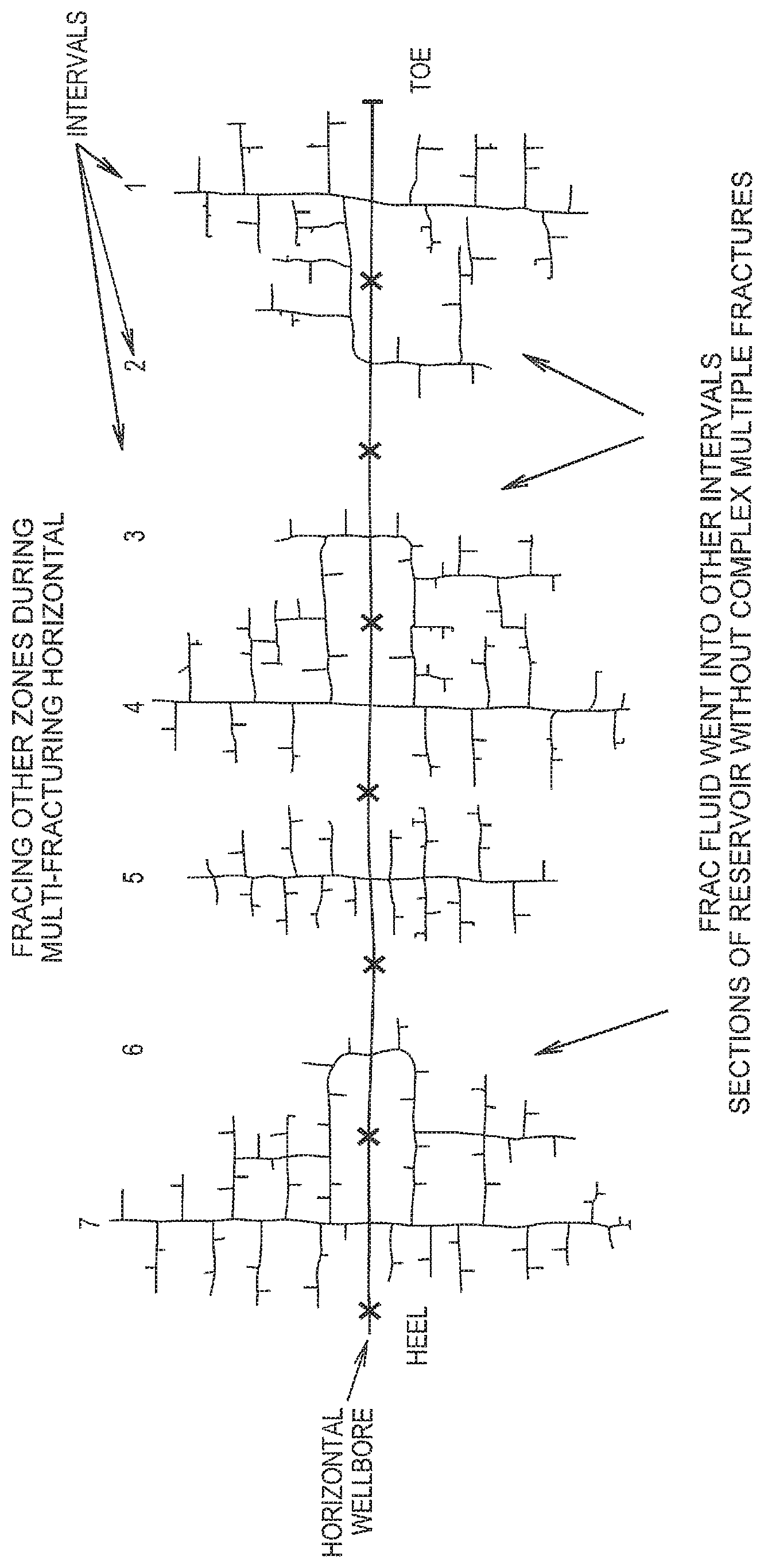
FIG. 1 illustrates the reduction in fracturing areas which are outside of intervals subjected to fracturing by use of the mixture disclosed herein.
DETAILED DESCRIPTION OF THE PREFERRED EMBODIMENTS
Well treatment fluids for use in the methods described herein contain particulates having the structural formula (I):
##STR00005##
or an anhydride thereof
wherein:
R.sup.1 is --COO--(R.sup.5O).sub.y--R.sup.4 or --H; R.sup.2 and R.sup.3 are selected from the group consisting of --H and --COO--(R.sup.5O).sub.y--R.sup.4; provided both R.sup.2 and R.sup.3 are --COO--(R.sup.5O).sub.y--R.sup.4 when R.sup.1 is --H and further provided only one of R.sup.2 or R.sup.3 is --COO--(R.sup.5O).sub.y--R.sup.4 when R.sup.1 is --COO--(R.sup.5O).sub.y--R.sup.4; R.sup.4 is --H or a C.sub.1-C.sub.6 alkyl group; R.sup.5 is a C.sub.1-C.sub.6 alkylene group; and each y is 0 to 5. Alternatively, the particulates may be an anhydride of the compound of structural formula (I).
In a preferred embodiment, R.sup.1 of the compound of formula (I) is --H and R.sup.3 is --COO--(R.sup.5O).sub.y--R.sup.4. In an especially preferred embodiment, the compound of formula (I) is phthalic acid (wherein y is 0 and R.sup.1 and R.sup.4 are --H). In another preferred embodiment, the compound of formula (I) is phthalic acid anhydride.
In another preferred embodiment, R.sup.2 of the compound of formula (I) is --H and R.sup.1 and R.sup.3 are --COO--(R.sup.5O).sub.y--R.sup.4. In an especially preferred embodiment, the compound of formula (I) is terephthalic acid (wherein y is 0 and R.sup.2 and R.sup.4 are --H). In another preferred embodiment, the compound of formula (I) is terephthalic acid anhydride.
Still in another preferred embodiment, R.sup.3 is --H and R.sup.1 and R.sup.2 of the compound of formula (I) is --COO--(R.sup.5O).sub.y--R.sup.4. In an especially preferred embodiment, the compound of formula (I) is isophthalic acid (wherein y is 0 and R.sup.3 and R.sup.4 are --H). In another preferred embodiment, the compound of formula (I) is isophthalic acid anhydride.
When the aromatic compounds of formula (I) are used in a mixture with aliphatic polyesters, the aliphatic polyesters may include those having the general formula of repeating units shown below:
##STR00006## where n is an integer between 75 and 10,000 and R is selected from the group consisting of hydrogen, alkyl (preferably a C.sub.1-C.sub.6 alkyl), aryl (preferably a C.sub.6-C.sub.18 aryl), alkylaryl (preferably having from about 7 to about 24 carbon atoms), acetyl, heteroatoms (such as oxygen and sulfur) and mixtures thereof. In a preferred embodiment, the weight average molecular weight of the aliphatic polyester is between from about 100,000 to about 200,000.
A preferred aliphatic polyester is poly(lactide). Poly(lactide) is synthesized either from lactic acid by a condensation reaction or more commonly by ring-opening polymerization of cyclic lactide monomer. Since both lactic acid and lactide can achieve the same repeating unit, the general term poly(lactic acid) as used herein refers to formula (II) without any limitation as to how the polymer was made such as from lactides, lactic acid, or oligomers, and without reference to the degree of polymerization.
The lactide monomer exists generally in three different forms: two stereoisomers L- and D-lactide and racemic D,L-lactide (meso-lactide). The oligomers of lactic acid, and oligomers of lactide may be defined by the formula:
##STR00007## where m is an integer: 2.ltoreq.m.ltoreq.75. Preferably m is an integer: 2.ltoreq.m.ltoreq.10. These limits correspond to number average molecular weights below about 5,400 and below about 720, respectively. The chirality of the lactide units provides a means to adjust, inter alia, degradation rates, as well as physical and mechanical properties. Poly(L-lactide), for instance, is a semi-crystalline polymer with a relatively slow hydrolysis rate. Poly(D,L-lactide) may be a more amorphous polymer with a resultant faster hydrolysis rate. The stereoisomers of lactic acid may be used individually or combined. Additionally, they may be copolymerized with, for example, glycolide or other monomers like .epsilon.-caprolactone, 1,5-dioxepan-2-one, trimethylene carbonate, or other suitable monomers to obtain polymers with different properties or degradation times. Additionally, the lactic acid stereoisomers may be modified by blending high and low molecular weight polylactide or by blending polylactide with other polyesters.
As an alternative to the aliphatic polyesters of formula (II), the phthalic acid or phthalic acid anhydride of formula (I) may be used to enhance the activity of other aliphatic polyesters including star- and hyper-branched aliphatic polyesters polymers as well as other homopolymers, random, block and graft copolymers. Such suitable polymers may be prepared by polycondensation reactions, ring-opening polymerizations, free radical polymerizations, anionic polymerizations, carbocationic polymerizations, and coordinative ring-opening polymerization for, e.g., lactones, and any other suitable process. Specific examples of suitable polymers include polysaccharides such as dextran or cellulose; chitin; chitosan; proteins; orthoesters; poly(glycolide); poly(c-caprolactone); poly(hydroxybutyrate); poly(anhydrides); aliphatic polycarbonates; poly(orthoesters); poly(amino acids); poly(ethylene oxide); and polyphosphazenes.
In a preferred embodiment, the particulates of formula (I), as well as the mixture of particulates of formula (I) and (II) may be of any size or shape. For instance, the particulates may be substantially spherical, such as being beaded, or pelleted. Further, the particulates may be non-beaded and non-spherical such as an elongated, tapered, egg, tear-drop or oval shape or mixtures thereof. For instance, the particulates may have a shape that is cubic, bar-shaped (as in a hexahedron with a length greater than its width, and a width greater than its thickness), cylindrical, multi-faceted, irregular, or mixtures thereof. In addition, the particulates may have a surface that is substantially roughened or irregular in nature or a surface that is substantially smooth in nature. Moreover, mixtures or blends of particulates having differing, but suitable shapes for use in the disclosed method, may be further employed.
The particulates used herein have a sized particle distribution effective to block the penetration of the fluid into the high permeability zone of the formation. In an embodiment, the particle size distribution of the particulates is in the range from about 0.1 micron to about 1.0 millimeter.
When used in combination with the aliphatic polyesters of formula (II), the weight ratio of particulates of formula (I) and particulates of formula (II) introduced into the well is typically between from about 90:10 to about 10:90 and more typically between from about 40:60 to about 60:40.
Typically, the amount of compound(s) of formula (I) in the fluid introduced into the well is between from about 0.01 to about 30 weight percent (based on the total weight of the fluid). When a mixture of particulates of the compound of formula (I) and the compound of formula (II) are used, the amount of particulates of formula (I) in the fluid introduced into the well is between from about 0.01 to about 30 weight percent and the amount of the compound(s) of formula (II) in the fluid is from about 0.01 to about 3% by weight.
The particulates of formula (I) are particularly effective when placed into wells having bottomhole temperatures between from about 175.degree. F. to about 250.degree. F. The particulates may be partially, but not fully, dissolved at in-situ reservoir conditions. Typically, the particulates are fully dissolved over time. In most instances, the particulates are fully dissolved after completion of the well treatment operation.
When a mixture of particulates of formula (I) and (II) are used, the mixture is particularly effective when placed into wells having bottomhole temperatures between from about 140.degree. F. to about 190.degree. F. The compound of formula (I) enhances the performance of the aliphatic polyester of formula (II) since in the absence of the compound of formula (I) the aliphatic polyester is non-dissolvable or sparingly soluble at bottomhole temperatures less than 250.degree. F. Thus, when used in combination with the compound of formula (I), the aliphatic polyesters may be used in reservoirs having a bottomhole temperature less than 250.degree. F. Typically, the particulates of the mixture are fully dissolved over time at such bottomhole temperatures.
The fluid of the treatment fluid containing the particulates may be any fluid suitable for transporting the particulates into the reservoir and/or subterranean formation such as water, salt brine and slickwater. Suitable brines including those containing potassium chloride, sodium chloride, cesium chloride, ammonium chloride, calcium chloride, magnesium chloride, sodium bromide, potassium bromide, cesium bromide, calcium bromide, zinc bromide, sodium formate, potassium formate, cesium formate, sodium acetate, and mixtures thereof. The percentage of salt in the water preferably ranges from about 0% to about 60% by weight, based upon the weight of the water.
The fluid of the treatment fluid may be foamed with a liquid hydrocarbon or a gas or liquefied gas such as nitrogen or carbon dioxide.
In addition, the fluid may further be foamed by inclusion of a non-gaseous foaming agent. The non-gaseous foaming agent may be amphoteric, cationic or anionic. Suitable amphoteric foaming agents include alkyl betaines, alkyl sultaines and alkyl carboxylates, such as those disclosed in U.S. Patent Publication No. 2010/0204069, herein incorporated by reference. Suitable anionic foaming agents include alkyl ether sulfates, ethoxylated ether sulfates, phosphate esters, alkyl ether phosphates, ethoxylated alcohol phosphate esters, alkyl sulfates and alpha olefin sulfonates. Suitable cationic foaming agents include alkyl quaternary ammonium salts, alkyl benzyl quaternary ammonium salts and alkyl amido amine quaternary ammonium salts.
The pH of the fluid containing the particulates may further be adjusted when desired. When adjusted, it typically has a value of about 6.5 or more, 7 or more, 8 or more, 9 or more, between 9 and 14, and, most preferably, between 7.5 and 9.5. The pH may be adjusted by any means known in the art, including adding acid or base to the fluid, or bubbling carbon dioxide through the fluid.
The fluid may be gelled or non-gelled. Typically, the fluid is gelled by the inclusion of a viscosifying agent such as a viscosifying polymer or viscoelastic fluid. The fluid may contain a crosslinking agent though a crosslinking agent is not required. Generally, the viscosity of the fluid is greater than or equal to 10 cP at room temperature.
In a preferred embodiment, the particulates of the diverter are used as a diverter in the stimulation of a subterranean formation penetrated by a well where it may be introduced into productive zones of a formation having various permeabilities. The bottomhole temperature of the reservoir may be less than 250.degree. F. and may be as low as 140.degree. F. The particulates can divert a well treatment fluid from a high permeability zone to a low permeability zone of a subterranean formation at such bottomhole temperatures. Since conductivity is permeability multiplied by injection geometry, this is synonymous to the statement that the particulates can divert a well treatment fluid from a highly conductive primary fracture(s) to less conductive secondary fractures. Further, since conductivity is a function of the relative resistance to inflow, the reference to a conductive fracture as used herein is considered synonymous to a conductive reservoir area.
By bridging the flow spaces on the face of the formation, the solid particulates form a filter cake. The pressure drop though the filter cake increases the flow resistance and diverts treatment fluid to less permeable zones of the formation. The filter cake is more easily formed when at least 60%, more preferably 80%, of the particulates of formula (I) or particulates of the mixture of (I) and (II) within the well treatment fluid have a particle size between from about 150 .mu.m to about 2000 .mu.m.
When used in stimulation operations, the particle size of the particulates is such that the particulates may form a bridge on the face of the rock. Alternatively, the particle size of the particulates may be such that they can flow into the fracture and thereby pack the fracture to reduce the permeability of at least some of the fractures in the formation.
When employed in acid fracturing, the particulates are of sufficient size to bridge the flow space (created from the reaction of the injected acid with the reservoir rock) without penetration of the matrix. By being filtered at the face of the formation, a relatively impermeable or low permeability filter cake is created on the face of the formation. The pressure drop through the filter cake increases the flow resistance and diverts treatment fluid to less permeable zones of the formation.
When used as a diverter, the fluid containing the particulates may be pumped directly to the high permeability zone of the well formation. The majority of the diverting fluid will enter into the high permeability or non-damaged zone and form a temporary "plug" or "viscous pill" while the lower permeability zone has little invasion. This temporary "viscous pill" causes a pressure increase and diverts the fluid to a lower permeability portion of the formation. The particulates are capable of being spread deeper into subterranean formations than diverting agents of the prior art.
Once in place, the viscous pill formed from the diverter will have a finite depth of invasion which is related to the pore throat diameter. For a given formation type, the invasion depth is directly proportional to the nominal pore throat diameter of the formation. Since varying depths of invasion occur throughout the formation based upon the varying permeability or damage throughout the treated zone, the ability of the treatment fluid to invade into pore throats is dependent on the difference between pore throat sizing of the damaged and non-damaged formation. Invasion depths will normally be greater in the cleaner or non-damaged portion of the formation (larger pore throats) than in the lower permeability or damaged zones (smaller or partially filled pore throats). With a greater depth of invasion in the cleaner sections of the formation, more of the diverter may be placed in these intervals.
The mixture defined herein further has particular applicability when used to increase the productivity of hydrocarbons far field from the wellbore as well as near wellbore. For instance, the mixture may be used to increase the productivity of low permeability formations such as in stimulation operation where discrete intervals or clusters are formed along a horizontal wellbore. The particle size of the particulates of the fluid may be such that they are capable of flowing into the fracture and thereby pack the fracture in order to reduce the permeability of at least some of the fractures in the formation. The mixture defined herein thus may be used to increase the stimulated rock volume (SRV) of the formation between production areas and clusters by increasing the distribution of the area subjected to fracturing.
The mixture may also be used to create a complex fracture network within a formation. Thus, the mixture may be used as a fracturing fluid and may be pumped into the formation at a pressure sufficient to create or enlarge a primary fracture. In other instances, a fracturing fluid not containing the mixture may be pumped into the formation. Such other fracturing fluids may include those fluids containing a viscosifying agent other than that of the mixture defined herein. Further, the fracturing fluid used to create or enlarge the fracture may be slickwater. After the primary fracture is created or enlarged, a second fluid containing the mixture defined herein may be pumped into the formation. At least one secondary fracture having a directional orientation distinct from the directional orientation of the primary fracture may be created. The second fluid diverts the flow of the second fluid into the secondary fracture. This process may be repeated and multiple fluids containing the mixture defined herein may be pumped into the formation to divert the flow of a preceding fluid. In this manner, a complex fracture network may be created consisting of multiple fractures in the formation originating from the primary fracture.
In another embodiment, the particle size of the compounds of formula (I) and (II) may be selected such that particulates of the mixture form a bridge on the face of the rock. In this manner, the particle size of the particulates are such that slugs containing the particulates of the mixture may be pumped into the formation, pass through the perforations or clusters and then form a bridge in the near-wellbore area within the fracture. Such packing of the fracture temporarily reduce the conductivity of at least some of the fractures in the formation. This, in turn, assists diversion of the fracturing fluid more evenly.
The mixture defined herein may further be used to further limit the fracturing of zones in formations (such as shale formations) which are known to exhibit non-uniform interval coverage. Microseismic mapping and well temperature logging often show poor frac fluid distribution across each interval and re-fracturing of nearby intervals. By directing the placement of fluid containing particulates of the mixture within the fractured zones, out of intervals fracturing areas are reduced. This is shown in FIG. 1.
Re-fracturing of a formation using the mixture disclosed herein is especially useful in the re-fracturing of horizontal wells. In such cases, a portion of the wellbore or the entire lateral of the wellbore may be perforated in a multitude of locations, sometimes dozens of locations, from the original fracture stimulation. Further, the wellbore may have new perforated clusters added during the re-fracturing operation that are intended to be fracture treated for the first time. With all of such perforations open, a pill or plug of a fluid containing the particulates of the mixture defined herein may be pumped into the formation. The particulates plug off the zones that are readily accepting the fluid most rapidly such that the fluid moves toward the areas of the formation which are more difficult to treat.
Where the particulates are components of an acidizing solution, the amount of aqueous acid in the fluid may range from about 70 to about 99 volume percent and the strength of the acid may be greater than or equal to 10%. The acid reacting, with the rock, lowers the acid strength to a concentration less than 15%.
In another preferred embodiment, the particulates are used as a fluid loss pill in the control of leak-off of the treatment fluid to the formation. The fluid loss pill is a specific fluid that is injected into the well and designed to alleviate the fluid loss, particularly from completion fluids, into the formation. In specific situations, such as during perforation of the well casing, it is considered particularly advantageous to incorporate a fluid loss pill in addition to the normal fluid loss control additives typically included in the wellbore treatment fluids. The operator may control leak-off of the treatment fluid to the formation by controlling the size differential between the particulates and the pore throats. Solid particulates of formula (I) or a mixture of particulates of formula (I) and (II) are deposited on the formation wall and form a substantially impermeable filter cake.
Particulates of formula (I) as well as a mixture of particulates of formula (I) and formula (II) may further be used in completion fluids. Completion fluids are utilized when conducting various completion operations in the producing formations. Such particulates seal off the face of the wellbore so that the fluid is not lost to the formation. The particulates are deposited and form a filter cake of the solids in the fluid over the surface of the wellbore without any loss of solids to the formation. As such, the particulates form a fluid bridge over the formation pores rather than permanently plugging the pores.
Fluids containing the particulates may also be useful as a sand control fluid. In one exemplary embodiment, a gravel pack operation may be carried out on a wellbore that penetrates a subterranean formation to prevent or substantially reduce the production of formation particles into the wellbore from the formation during production of formation fluids. A screen assembly such as is known in the art may be placed or otherwise disposed within the wellbore so that at least a portion of the screen assembly is disposed adjacent the subterranean formation. A slurry including particulates of formula (I) or a mixture of particulates of formula (I) and (II) and a treatment fluid for carrying the particulates may then be introduced into the wellbore and placed adjacent the subterranean formation by circulation or other suitable method so as to form a fluid-permeable pack in an annular area between the exterior of the screen and the interior of the wellbore. This permeable pack is capable of reducing or substantially preventing the passage of formation particles from the subterranean formation into the wellbore during production of fluids from the formation, while at the same time allowing passage of formation fluids from the subterranean formation through the screen into the wellbore.
The particulates described herein may further be used in well intervention applications, such as wellbore clean-out wherein solid debris, especially hydrophobic materials, are removed from the wellbore in order to ensure unobstructed hydrocarbon recovery. For instance, fluid containing particulates of formula (I) or a mixture of particulates of (I) and (II) may be introduced into the wellbore, such as by coiled tubing, to remove hydrophobic particulate materials remaining in the wellbore. In an embodiment, the particulates may agglomerate the hydrophobic particulate material and the agglomerate may then be removed or carried upward to the surface. Clean-out may also occur the well is drilled and prior to stimulation. The use of the particulates in such clean-out operations cuttings are removed that could adversely affect the subsequent injection of fracturing fluid.
While the particulates are most typically a component of the treatment fluid (i.e., acidizing fluid, hydraulic fracturing fluid, wellbore completion fluid, etc.), a fluid containing particulates of formula (I), as well as a mixture of particulates of formula (I) and (II) may be pumped into the wellbore followed by or prior to the addition of the well treatment fluid (i.e., acidizing fluid, hydraulic fracturing fluid, wellbore completion fluid, etc.).
For instance, when used in hydraulic fracturing, the particulates perform as a diverter and may be a component of the hydraulic fracturing fluid or may be pumped into the formation as a component of a pad fluid. Further, in an acid fracturing operation, a stage of acid may preferably be injected following introduction of a fluid containing the diverter.
Further, a fluid containing the particulates of formula (I), as well as a mixture of particulates of formula (I) and (II), may be pumped into the wellbore in alternative stages and may be separate by spacer fluids. The spacer fluid typically contains a salt solution such as NaCl, KCl and/or NH.sub.4Cl. For instance, the loss in viscosity of a fluid loss pill may require additional diverter stages to be pumped. In addition, alternate stages may be required to more appropriately treat a heterogeneous formation. For instance, when used in an acid stimulation operation, it may be desirable to alternate the pumping of acid stimulation fluids and diverting fluids. An exemplary pumping schedule may be (i) pumping an acid stimulation fluid; (ii) optionally pumping a spacer fluid; (iii) pumping a fluid containing the diverter; (iv) optionally pumping a spacer fluid; and then repeating the cycle of steps (i), (ii), (iii) and (iv).
The fluid containing the particulates may further contain additional well treatment fluid additives. These include one or more conventional additives to the well service industry such as a gelling agent, fluid loss additives, gel breaker, surfactant, demulsifier, biocide, mutual solvent, surface tension reducing agent, defoaming agent, demulsifier, non-emulsifier, scale inhibitor, gas hydrate inhibitor, enzyme breaker, oxidative breaker, buffer, clay stabilizer, acid, buffer, solvent or a mixture thereof.
Where the fluid containing the particulates is an acidizing fluid, it may be preferable to include within the fluid a corrosion inhibitor, a corrosion inhibitor intensifier, or a combination thereof. The purpose of these additives is to reduce the corrosive effects that the acids may have on the well tubulars. Suitable corrosion inhibitors can include alkali metal nitrites, nitrates, phosphates, silicates and benzoates. Representative suitable organic inhibitors include hydrocarbyl amine and hydroxy-substituted hydrocarbyl amine neutralized acid compound, such as neutralized phosphates and hydrocarbyl phosphate esters, neutralized fatty acids (e.g., those having 8 to about 22 carbon atoms), neutralized carboxylic acids (e.g., 4-(t-butyl)-benzoic acid and formic acid), neutralized naphthenic acids and neutralized hydrocarbyl sulfonates. Mixed salt esters of alkylated succinimides are also useful. Corrosion inhibitors can also include the alkanolamines such as ethanolamine, diethanolamine, triethanolamine and the corresponding propanolamines as well as morpholine, ethylenediamine, N,N-diethylethanolamine, alpha- and gamma-picoline, piperazine and isopropylaminoethanol.
Fluids containing particulates of formula (I), as well as a mixture of particulates of formula (I) and (II), may also have an internal breaker built into the system to insure that the fluid viscosity can be reduced after a period of time. The internal breaker may also be an oxidizer such as, but not limited to, persulfates, such as ammonia persulfate and sodium persulfate, and peroxidizers such as hydrogen peroxide.
The formation subjected to the treatment of the disclosure may be a hydrocarbon or a non-hydrocarbon subterranean formation. The high permeability zone of the formation into which the fluid containing the diverter is pumped may be natural fractures. When used with low viscosity fracturing fluids, the particulates of formula (I), as well as a mixture of particulates of formula (I) and (II) are capable of diverting fracturing fluids to extend fractures and increase the stimulated surface area.
The disclosure has particular applicability to the stimulation of carbonate formations, such as limestone, chalk or dolomite as well as subterranean sandstone or siliceous formations in oil and gas wells, including quartz, clay, shale, silt, chert, zeolite, or a combination thereof.
In another preferred embodiment, the diverter is introduced into coal beds having a series of natural fractures, or cleats, for the recovery of natural gases, such as methane, and/or sequestering a fluid which is more strongly adsorbing than methane, such as carbon dioxide and/or hydrogen sulfide.
EXAMPLES
The following designations are used in the Example:
A: a 90:10 v/v mixture of phthalic anhydride:phthalic acid, 20/40 mesh, melting range.sup.1: 268-270.degree. F.;
B: a 85:15 v/v mixture of phthalic anhydride:phthalic acid, 8/50 mesh, melting range: 268-356.degree. F.;
C: polylactic acid, 14/70 mesh, melting range: 298-329.degree. F.;
D: polylactic acid, 10/70 mesh, melting range: 336-345.degree. F.
C&D were prepared by grinding pellets of polylactic acid, commercially available as INGEO.RTM. 4340-D from NatureWorks LLC, to the designated size.
Example 1
Phthalic anhydride (obtained from a commercial supplier) and Sample A (8 g of each) were first diluted in 100 mL deionized water or HCl 15% for 20 hours at 180.degree. F., and then left for 3 hours at room temperature. The mixture was vacuum filtrated with 100 mL water and dried for 24 hours at 160.degree. F. The results are set forth in Table I.
TABLE-US-00001 TABLE I Melting Dissolved Range.sup.2, Sample (%) .degree. F. Solvent Commercial Phthalic Anhydride 6 403 Deionized water Sample A 7.5 401 Deionized water Sample A, crushed 4 397-399 Deionized water Commercial Phthalic Anhydride 4 412 HCl 15% Sample A 0 410 HCl 15% Sample A, crushed 16 415 HCl 15% .sup.1Melting range represents the temperature at which the solid started to soften to when it was completely melted. .sup.2Undissolved sample, not starting material.
FTIR and melting point of the recovered undissolved samples showed that the remaining phthalic anhydride had converted into phthalic acid.
Example 2
Samples of Sample A (each 5 g) were diluted in 100 mL of either deionized water (DI) or tap water for (1) 54 hours at 180.degree. F. and (2) 64 hours at 140.degree. F. and then left to cool at room temperature. The solids were vacuum filtrated with 100 mL water and dried for 24 h at 160.degree. F. The results are set forth in Table II).
TABLE-US-00002 TABLE II 54 hr PERCENT 64 hr PERCENT SOLUBILITY @ SOLUBILITY @ 140.degree. F. 180.degree. F. tap tap water DI water DI 18.5 13.4 5.6 9.3
The FTIR and melting point of the recovered undissolved samples showed that the remaining phthalic anhydride had converted into phthalic acid. Table II illustrates that more phthalic anhydride was converted to phthalic acid at higher temperatures. Sample A was thus more suitable for lower temperature applications.
Example 3
Different initial weights of Sample A were diluted in 18 mL of deionized water for 24 hours at 250.degree. F. using a digestion vessel. After leaving the samples to cool, they were vacuum filtrated with deionized water and dried for 24 hours at 160.degree. F. The results are set forth in Table III. The FTIR and melting point of the recovered undissolved samples showed that the remaining phthalic anhydride had converted into phthalic acid.
TABLE-US-00003 TABLE III Initial Weight (g) % dissolved 1 55.6 0.5 83.7 0.25 100 0.1 100 0.05 100 0.025 100
Example 4
Different initial weights of Sample C were tested for solubility by using a digestion vessel (at 250.degree. F. for 24 hours) and diluting in 18 mL of DI water, using different sample concentrations. The results are set forth in Table IV.
TABLE-US-00004 TABLE IV Amount (g) % Dissolved 1.000 100 0.500 100 0.250 100 0.100 100 0.050 100 0.025 100
Example 5
Samples were dissolved in water and heated in a water bath. After reaching room temperature, the samples were filtered via a vacuum. The recovered material was then dried overnight and the percentage of dissolved solids was calculated based on the amount of sample retained on a Whatman #41 filter paper. All samples were allowed to dry for at least 24 hours at approximately 160.degree. F. The samples (2.5 total) were then tested for solubility in 50 mL of deionized water using different temperatures (heating for 24 or 48 hours). The 1:1 mixture of Sample B and Sample C were made by mixing equal amounts of each product (1.25 g) and diluting in 50 mL total deionized water. The results are set forth in Table V:
TABLE-US-00005 TABLE V 24 hr 48 hr SAMPLE 140.degree. F. 180.degree. F. 80.degree. F. 180.degree. F. 300.degree. F. B 8.7 21.6 19.9 5.4 11.0 B 6.1 n/a 24.1 n/a 10.5 C 0.31 1.1 0.99 9.9 99.3 C 0.30 n/a 0.98 n/a 99.2 B:C 10.9 31.1 13.8 30.1 90.5 B:C 10.2 n/a 12.9 n/a 87.2
Example 6
Additional solubility tests were performed using Sample B and Sample D (2.5 g total) in 50 mL of deionized water using different temperatures (heating for 24 or 48 hr). The 1:1 mixture of Sample B:Sample D was made by mixing equal amounts of each product (1.25 g) and diluting in 50 mL deionized water. The results are set forth in Table VI:
TABLE-US-00006 TABLE VI 24 hr 48 hr SAMPLE 150.degree. F. 180.degree. F. 150.degree. F. B 24.8 21.6 16.5 D 0.2 0.24 0.1 1:1 B:D 20.2 23.1 16.7
The Examples illustrate that phthalic anhydride/phthalic acid is more suitable as a diverting agent in lower temperatures (180-250.degree. F.) applications and polylactic acid is more suitable as a diverting agent at higher temperature higher temperature (>250.degree. F.) applications. The Examples further illustrate, based on the solubility results, that phthalic anhydride/phthalic acid acts enhances lowering the temperature at which polylactic acid dissolves. When mixed with polylactic acid, the Examples illustrate that phthalic anhydride/phthalic acid acts to enhance the activity of polylactic acid, while lowering the temperature at which polylactic dissolves. Thus, when mixed with phthalic anhydride/phthalic acid, polylactic acid may be used in lower temperature applications.
While exemplary embodiments of the disclosure have been shown and described, many variations, modifications and/or changes of the system, apparatus and methods of the present disclosure, such as in the components, details of construction and operation, arrangement of parts and/or methods of use, are possible, contemplated by the patent applicant(s), within the scope of the appended claims, and may be made and used by one of ordinary skill in the art without departing from the spirit or teachings of the disclosure and scope of appended claims. Thus, all matter herein set forth or shown in the accompanying drawings should be interpreted as illustrative, and the scope of the disclosure and the appended claims should not be limited to the embodiments described and shown herein.
* * * * *
C00001
C00002
C00003
C00004
C00005
C00006
C00007
C00008
C00009
C00010
C00011
C00012
C00013

D00000

D00001
XML
uspto.report is an independent third-party trademark research tool that is not affiliated, endorsed, or sponsored by the United States Patent and Trademark Office (USPTO) or any other governmental organization. The information provided by uspto.report is based on publicly available data at the time of writing and is intended for informational purposes only.
While we strive to provide accurate and up-to-date information, we do not guarantee the accuracy, completeness, reliability, or suitability of the information displayed on this site. The use of this site is at your own risk. Any reliance you place on such information is therefore strictly at your own risk.
All official trademark data, including owner information, should be verified by visiting the official USPTO website at www.uspto.gov. This site is not intended to replace professional legal advice and should not be used as a substitute for consulting with a legal professional who is knowledgeable about trademark law.