Aircraft having hydraulic support struts between fuselage and wings
Klettke April 27, 2
U.S. patent number 10,988,234 [Application Number 15/455,724] was granted by the patent office on 2021-04-27 for aircraft having hydraulic support struts between fuselage and wings. This patent grant is currently assigned to Airbus Operations GmbH. The grantee listed for this patent is Airbus Operations GmbH. Invention is credited to Marcus Klettke.

| United States Patent | 10,988,234 |
| Klettke | April 27, 2021 |
Aircraft having hydraulic support struts between fuselage and wings
Abstract
An aircraft with a fuselage and with wings connected thereto, wherein a support strut extends between the fuselage and each of the wings, which support strut is connected both to the fuselage and to the wing. The support strut has a hydraulic working cylinder, which can be pressurized with hydraulic fluid in a controlled manner for the purpose of pivoting the wing.
| Inventors: | Klettke; Marcus (Hamburg, DE) | ||||||||||
|---|---|---|---|---|---|---|---|---|---|---|---|
| Applicant: |
|
||||||||||
| Assignee: | Airbus Operations GmbH
(Hamburg, DE) |
||||||||||
| Family ID: | 1000005513778 | ||||||||||
| Appl. No.: | 15/455,724 | ||||||||||
| Filed: | March 10, 2017 |
Prior Publication Data
| Document Identifier | Publication Date | |
|---|---|---|
| US 20170247103 A1 | Aug 31, 2017 | |
Related U.S. Patent Documents
| Application Number | Filing Date | Patent Number | Issue Date | ||
|---|---|---|---|---|---|
| PCT/EP2015/070624 | Sep 9, 2015 | ||||
Foreign Application Priority Data
| Sep 12, 2014 [DE] | 10 2014 113 218 | |||
| Current U.S. Class: | 1/1 |
| Current CPC Class: | B64C 1/26 (20130101); B64C 3/38 (20130101); F15B 11/10 (20130101); B64D 41/00 (20130101); F15B 2211/40 (20130101) |
| Current International Class: | B64C 3/38 (20060101); B64C 1/26 (20060101); B64D 41/00 (20060101); F15B 11/10 (20060101) |
References Cited [Referenced By]
U.S. Patent Documents
| 1783529 | December 1930 | Waterman |
| 2186558 | January 1940 | Rouanet |
| 2603435 | July 1952 | Metzler |
| 5078338 | January 1992 | O'Neill et al. |
| 5645250 | July 1997 | Gevers |
| 5915650 | June 1999 | Petrovich |
| 9597939 | March 2017 | Anderson et al. |
| 2010/0059623 | March 2010 | Cazals et al. |
| 102498002 | Jun 2012 | CN | |||
| 483040 | Sep 1929 | DE | |||
| 525387 | Oct 1931 | DE | |||
| 907502 | Mar 1954 | DE | |||
| 421352 | Feb 1911 | FR | |||
Other References
|
Chinese Office Action and Search Report for Chinese Application No. 20150052284.1 dated Jul. 2, 2018. cited by applicant . Chinese Office Action for Application No. 201580052284.1 dated Mar. 4, 2019. cited by applicant . English Translation of the IPRP with Written Opinion for Application No. PCT/EP2015/070624 dated Mar. 14, 2017. cited by applicant . German Search Report for Application No. 102014113218 dated Mar. 30, 2015. cited by applicant . International Search Report for Application No. PCT/EP2015/070624 dated Nov. 5, 2015. cited by applicant. |
Primary Examiner: O'Hara; Brian M
Assistant Examiner: Dixon; Keith L
Attorney, Agent or Firm: Jenkins, Wilson, Taylor & Hunt, P.A.
Parent Case Text
CROSS-REFERENCE TO RELATED APPLICATIONS
This application is a continuation of International Application No. PCT/EP2015/070624 filed Sep. 9, 2015, which claims priority to German Patent Application No. 10 2014 113 218.1 filed Sep. 12, 2014, the entire disclosures of which are incorporated by reference herein.
Claims
The invention claimed is:
1. An aircraft comprising: a fuselage; wings connected to the fuselage; support struts, which extend between, and are connected to, the fuselage and a corresponding one of the wings, wherein each support strut comprises a hydraulic working cylinder, which can be pressurized with hydraulic fluid in a controlled manner for pivoting the corresponding one of the wings to which the support strut is connected, wherein each of the support struts comprises a piston rod connected between the working cylinder and the corresponding one of the wings to which the support strut is attached, and wherein the working cylinder is coupled with a hydraulic motor and an electric motor/generator, so that a movement of the piston rod caused by wing vibrations or wing oscillations drives the hydraulic motor and thus the motor/generator; and one or more valves in a flow path of the hydraulic fluid, wherein the one or more valves are configured for activation such that a flow resistance for the hydraulic fluid is adjustable.
2. The aircraft according to claim 1, wherein the hydraulic working cylinder is connected to the fuselage.
3. The aircraft according to claim 1, wherein the working cylinder is fixedly attached to the fuselage, and wherein a free end of the piston rod is swivelably connected to the corresponding one of the wings to which the support strut is connected by the piston rod.
4. The aircraft according to claim 1, wherein the working cylinder is produced with a lightweight construction.
5. The aircraft according to claim 4, wherein the working cylinder comprises fiber-reinforced plastic.
6. The aircraft according to claim 1, wherein the motor/generator is configured to, from the movement of the piston rod that drives the hydraulic motor and the motor/generator, generate electricity that can be stored and/or used for operating the aircraft.
Description
TECHNICAL FIELD
The disclosure herein relates to an aircraft with a fuselage and with wings connected thereto, wherein a support strut extends between the fuselage and each of the wings, which support strut is connected both to the fuselage and to the wing.
BACKGROUND
Concepts for aircraft are known which are to be entirely or partially electrically powered (e.g., Boeing SUGAR Volt), where support struts are provided between the fuselage and wings because the wings have a considerable wingspan and require support.
A problem addressed by the disclosure herein is to form an aircraft in such a way that the provided support struts, in addition to supporting the respective wing, have additional functions with respect to the fuselage.
In order to solve this problem, an aircraft of the type mentioned above is formed according to the disclosure herein such that the support strut has a hydraulic working cylinder, which can be pressurized with hydraulic fluid in a controlled manner for the purpose of pivoting the wing.
Pressurizing the working cylinder with hydraulic fluid changes its length and thus also the position of the wing relative to the aircraft fuselage. A simultaneous or synchronous adjustment of the working cylinders by the same amounts produces a simultaneous corresponding adjustment of the wing positions, which allows the wing assembly to be adapted to a variety of different fueling and loading situations. This adaptation can take place both before take-off of the aircraft and during the flight.
It is also possible to differently or asynchronously pressurize the working cylinders with hydraulic fluid, so that the wings are displaced differently and a rolling motion of the aircraft is produced which is otherwise usually generated by ailerons.
SUMMARY
In one preferred embodiment of the disclosure herein, the cylinder body of the working cylinder is connected to the fuselage, and the piston of the working cylinder can be connected to a section of a support strut which extends to the wing, or, in the case of sufficient piston length, to the wing. It is also possible to fixedly attach the cylinder of the working cylinder to the fuselage and to connect the free end of the piston rod to the end of the support strut which is close to the fuselage via a swiveling lever.
During normal flight, vibrations or oscillations are produced, which act on the working cylinders of the support struts and bring about shifting of the piston. These shifting movements occur more or less rapidly depending on the resistance which works against the shifting of hydraulic fluid in the working cylinder. In one preferred embodiment of the disclosure herein, the valves lying in the flow path of the hydraulic fluid can be controlled such that the flow resistance of the hydraulic fluid is adjustable. The wings can thus be adjusted to be more flexible or more rigid.
In another embodiment of the disclosure herein, the respective working cylinder is coupled with a hydraulic motor and an electric motor/generator, so that the piston movement caused during flight by wing vibrations or wing oscillations drives the hydraulic motor and thus the motor/generator.
Such a construction is known as so-called GenShock technology for automobile suspension. The application in an aircraft according to the disclosure herein allows electricity to be generated from the piston movements produced by the wing vibrations or wing oscillations when the motor/generator functions as a generator. This electricity can be stored and used for operating the aircraft.
Since significant importance is placed on obtaining weight reductions in aircraft, lightweight-construction working cylinders are preferably used according to the invention, for example, working cylinders with cylinders comprising or consisting of fiber-reinforced plastic, of the sort produced by Parker Hannifin Corp., Cleveland, Ohio, U.S.A., for example.
BRIEF DESCRIPTION OF THE DRAWINGS
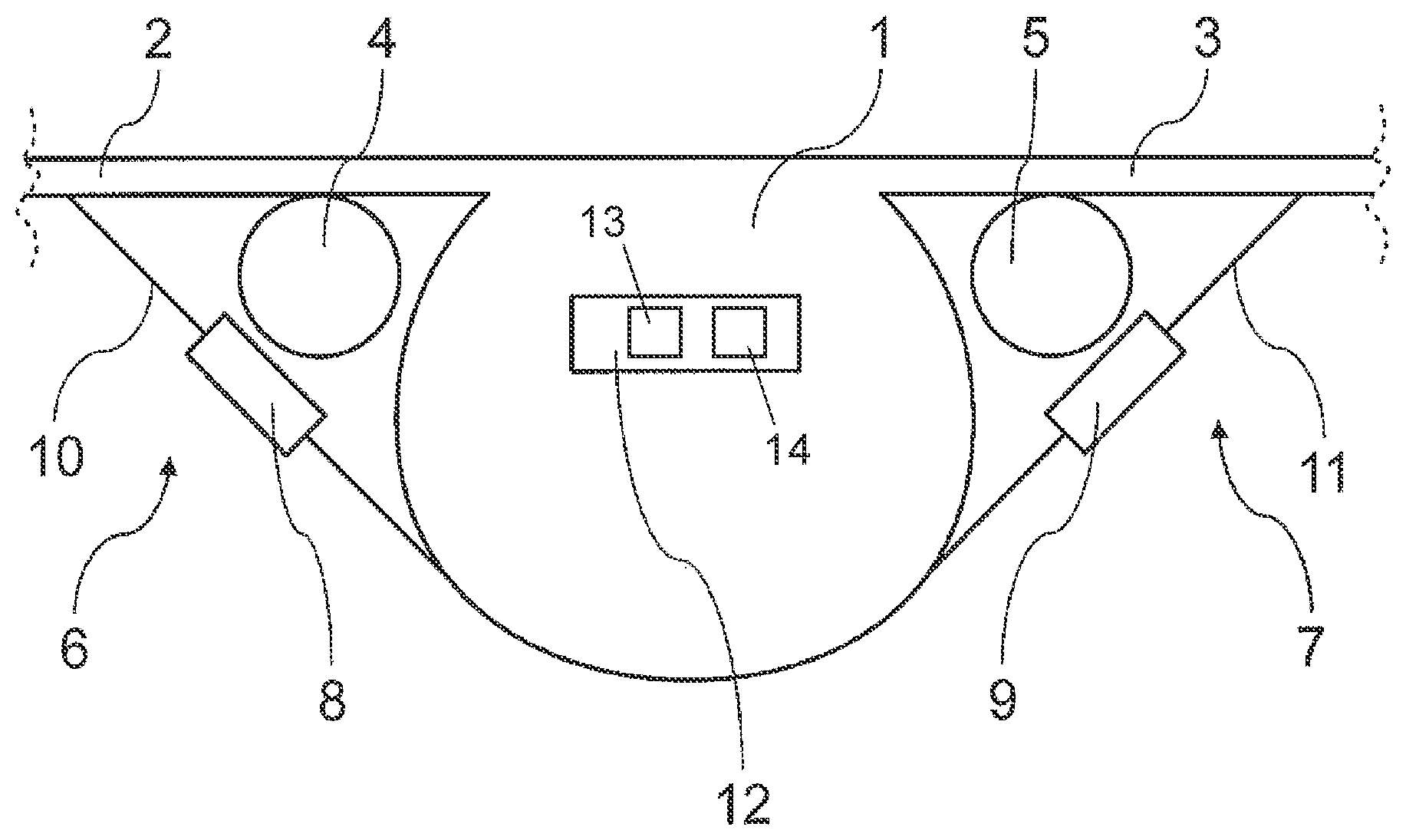
The disclosure herein is explained in greater detail below with reference to the greatly simplified schematic diagram of FIG. 1 showing an exemplary embodiment.
DETAILED DESCRIPTION
The depicted aircraft has a fuselage 1 and wings 2, 3, to which propulsion units 4, 5 are usually attached. A support strut 6 extends between the fuselage 1 and the wing 2 and a support strut 7 extends between the fuselage 1 and the wing 3, both of which support struts are identically constructed. Each of the support struts 6, 7 comprises a hydraulic working cylinder, the cylinder body 8, 9 of which is attached to the fuselage 1, while its piston rod 10, 11 is connected to the wings 2, 3. The entire piston rod 10, 11 can extend to the wing 2, 3 or it can be connected to a strut section which is attached to the wing 2, 3.
The hydraulic working cylinders 8, 10 and 9, 11 are each connected to a source of hydraulic fluid in a manner which is not depicted. This source can be part of a unit 12, which is housed at a suitable location in the fuselage 1 of the aircraft. This unit 12 comprises, in addition to the hydraulic fluid sources for the working cylinders 8, 10 and 9, 11, a hydraulic motor 13 and an electric motor/generator 14 for each of the working cylinders as well as corresponding control devices. These permit an activation of the electric motors/generators 14 in order to drive the hydraulic motors 13, which then supply hydraulic fluid to the working cylinders 8, 10 and 9, 11 or withdraw hydraulic fluid from them by suction.
The sources of hydraulic fluid, the hydraulic motors 13 and the electric motors/generators 14 can of course also be individually housed in the fuselage instead of the hydraulic motors 13 and the electric motors/generators 14 being grouped together in a unit.
If the electric motors/generators 14 are simultaneously activated at the same speed, the pistons of the working cylinders 8, 10 and 9, 11 are displaced correspondingly and both wings 2, 3 are thus either raised or lowered. An adaptation to fueling and loading states is thus obtained which enhances the efficiency of the aircraft.
If the electric motors/generators 14 are activated in such that one of the working cylinders is supplied with more and the other working cylinder with less or no hydraulic fluid, then one wing is pivoted more and the other wing is pivoted less or not at all. This leads to a rolling motion of the aircraft, of the sort usually generated by the aileron.
In this regard it is noted that an adjustment of the "rigidity" of the wings 2, 3 can also be realized by the hydraulic working cylinders 8, 9. For this purpose, the resistance of the hydraulic fluid to displacement in the cylinder 8, 9 is able to be changed, for example, by adjustable valves. The forces which, by wing vibrations and wing oscillations, act on the piston of the working cylinder 8, 10 and 9, 11 and which produce a displacement of hydraulic fluid, can then more or less easily shift the hydraulic fluid and thus the respective piston dependent on the set flow resistance of the hydraulic fluid, so that the wing is adjusted to be more flexible or more rigid. A more flexible wing adjustment increases the cabin comfort during turbulence for example.
Finally, it is also possible to use the piston movements resulting from wing vibrations and wing oscillations to supply hydraulic fluid to the corresponding hydraulic motor 13 and to use the thus obtained driving of the hydraulic motor 13 to drive the electric motor/generator 14, so that it functions as a generator and generates electricity, which can be used for operating the aircraft.
While at least one exemplary embodiment of the invention(s) herein is disclosed herein, it should be understood that modifications, substitutions and alternatives may be apparent to one of ordinary skill in the art and can be made without departing from the scope of this disclosure. This disclosure is intended to cover any adaptations or variations of the exemplary embodiment(s). In addition, in this disclosure, the terms "comprise" or "comprising" do not exclude other elements or steps, the terms "a", "an" or "one" do not exclude a plural number, and the term "or" means either or both. Furthermore, characteristics or steps which have been described may also be used in combination with other characteristics or steps and in any order unless the disclosure or context suggests otherwise. This disclosure hereby incorporates by reference the complete disclosure of any patent or application from which it claims benefit or priority.
* * * * *
D00000
D00001
XML
uspto.report is an independent third-party trademark research tool that is not affiliated, endorsed, or sponsored by the United States Patent and Trademark Office (USPTO) or any other governmental organization. The information provided by uspto.report is based on publicly available data at the time of writing and is intended for informational purposes only.
While we strive to provide accurate and up-to-date information, we do not guarantee the accuracy, completeness, reliability, or suitability of the information displayed on this site. The use of this site is at your own risk. Any reliance you place on such information is therefore strictly at your own risk.
All official trademark data, including owner information, should be verified by visiting the official USPTO website at www.uspto.gov. This site is not intended to replace professional legal advice and should not be used as a substitute for consulting with a legal professional who is knowledgeable about trademark law.