Device for storing elements
Mongrenier April 27, 2
U.S. patent number 10,987,276 [Application Number 16/338,839] was granted by the patent office on 2021-04-27 for device for storing elements. This patent grant is currently assigned to BIOLOG-ID. The grantee listed for this patent is BIOLOG-ID. Invention is credited to Jean-Claude Mongrenier.


| United States Patent | 10,987,276 |
| Mongrenier | April 27, 2021 |
Device for storing elements
Abstract
A device is provided for storing elements, each element including a first wireless communication unit. The device includes at least two drawer units each including: a drawer including a bottom defining at least one location for receiving an element; for each location, at least one second wireless communication unit including an antenna having a radiation-zone field, each antenna having a first state in which the antenna is activated and a second state in which the antenna is deactivated; and a data-processing unit able to control the activation and deactivation of the antenna of each second communication unit according to a control law.
| Inventors: | Mongrenier; Jean-Claude (Versailles, FR) | ||||||||||
|---|---|---|---|---|---|---|---|---|---|---|---|
| Applicant: |
|
||||||||||
| Assignee: | BIOLOG-ID
(Boulogne-Billancourt, FR) |
||||||||||
| Family ID: | 1000005512914 | ||||||||||
| Appl. No.: | 16/338,839 | ||||||||||
| Filed: | October 24, 2016 | ||||||||||
| PCT Filed: | October 24, 2016 | ||||||||||
| PCT No.: | PCT/EP2016/075498 | ||||||||||
| 371(c)(1),(2),(4) Date: | April 02, 2019 | ||||||||||
| PCT Pub. No.: | WO2018/065075 | ||||||||||
| PCT Pub. Date: | April 12, 2018 |
Prior Publication Data
| Document Identifier | Publication Date | |
|---|---|---|
| US 20190247276 A1 | Aug 15, 2019 | |
Foreign Application Priority Data
| Oct 3, 2016 [FR] | 1659518 | |||
| Current U.S. Class: | 1/1 |
| Current CPC Class: | G06K 7/10415 (20130101); A61J 1/10 (20130101); A61M 1/0286 (20140204); B65G 1/00 (20130101); A61M 1/0277 (20140204); B65G 1/02 (20130101); A61M 1/025 (20130101); B65G 2203/046 (20130101); A61J 2205/60 (20130101) |
| Current International Class: | A61J 1/10 (20060101); B65G 1/00 (20060101); G06K 7/10 (20060101); A61M 1/02 (20060101); B65G 1/02 (20060101) |
| Field of Search: | ;235/492,385 |
References Cited [Referenced By]
U.S. Patent Documents
| 3722964 | March 1973 | Chitester et al. |
| 4114559 | September 1978 | Rogen |
| 4608178 | August 1986 | Johansson |
| 4688026 | August 1987 | Scribner |
| 4857716 | August 1989 | Gombrich |
| 4871439 | October 1989 | Enzer |
| 4952913 | August 1990 | Pauley |
| 5100564 | March 1992 | Pall |
| 5263929 | November 1993 | Falcone |
| 5300060 | April 1994 | Nelson |
| 5507525 | April 1996 | Leuenberger |
| 5527472 | June 1996 | Bellotti |
| 5572873 | November 1996 | Lavigne |
| 5618662 | April 1997 | Lin |
| 5635917 | June 1997 | Todman |
| 5674741 | October 1997 | Watanabe |
| 5709472 | January 1998 | Prusik |
| 5769811 | June 1998 | Stacey |
| 5839806 | November 1998 | Liu |
| 5852590 | December 1998 | De La Huerga |
| 5936527 | August 1999 | Isaacman |
| 5969606 | October 1999 | Reber |
| 5980501 | November 1999 | Gray |
| 6032155 | February 2000 | De La Huerga |
| 6036101 | March 2000 | Hass |
| 6113554 | September 2000 | Gilcher |
| 6122704 | September 2000 | Hass |
| 6285285 | September 2001 | Mongrenier |
| 6294997 | September 2001 | Paratore |
| 6382416 | May 2002 | Gainey |
| 6613554 | September 2003 | Wei |
| 6712276 | March 2004 | Abali |
| 8342400 | January 2013 | Reese |
| 8770479 | July 2014 | Shoenfeld |
| 9275262 | March 2016 | Mongrenier |
| 2001/0006368 | July 2001 | Maloney |
| 2001/0033233 | October 2001 | Jentsch |
| 2001/0034614 | October 2001 | Fletcher-Haynes |
| 2002/0013523 | January 2002 | Csore |
| 2002/0023441 | February 2002 | Bara |
| 2002/0143320 | October 2002 | Levin |
| 2002/0183882 | December 2002 | Dearing |
| 2002/0186145 | December 2002 | Chainer |
| 2003/0072676 | April 2003 | Fletcher-Haynes |
| 2003/0099158 | May 2003 | De La Huerga |
| 2003/0132298 | July 2003 | Swartz |
| 2004/0044326 | March 2004 | Kranz |
| 2004/0046020 | March 2004 | Andreasson |
| 2004/0100380 | May 2004 | Lindsay |
| 2004/0151633 | August 2004 | De Gaulle |
| 2004/0166583 | August 2004 | De Gaulle |
| 2004/0212507 | October 2004 | Zweig |
| 2005/0091896 | May 2005 | Kotik |
| 2005/0127090 | June 2005 | Sayers |
| 2005/0276728 | December 2005 | Muller-Cohn |
| 2005/0285715 | December 2005 | Comunale |
| 2007/0018819 | January 2007 | Streeb |
| 2007/0023513 | February 2007 | Andreasson et al. |
| 2007/0123809 | May 2007 | Weiss |
| 2007/0220796 | September 2007 | Riley |
| 2007/0272746 | November 2007 | Ortiz |
| 2008/0104993 | May 2008 | Zenobi |
| 2008/0203160 | August 2008 | Lee |
| 2008/0208750 | August 2008 | Chen |
| 2008/0264962 | October 2008 | Schifman |
| 2008/0283596 | November 2008 | Ishida |
| 2008/0316045 | December 2008 | Sriharto |
| 2009/0134997 | May 2009 | Godlewski |
| 2009/0189816 | July 2009 | Nikitin |
| 2009/0251293 | October 2009 | Azevedo |
| 2010/0206948 | August 2010 | Seremjian |
| 2011/0140831 | June 2011 | Michael |
| 2011/0320322 | December 2011 | Roslak |
| 2012/0044054 | February 2012 | Hussain |
| 2015/0015373 | January 2015 | Mongrenier |
| 2016/0042313 | February 2016 | Caputo et al. |
| 2016/0113721 | April 2016 | Seremjian |
| 2017/0177832 | June 2017 | Caputo |
| 2017/0196128 | July 2017 | Elizondo, II |
| 2019/0220638 | July 2019 | Mongrenier |
| 2019/0307936 | October 2019 | Rushing |
| 403245 | Dec 1997 | AT | |||
| 2017236045 | Mar 2020 | AU | |||
| 2307517 | Oct 2000 | CA | |||
| 2545978 | Nov 2007 | CA | |||
| 2572649 | Jan 2017 | CA | |||
| 2280671 | May 1998 | CN | |||
| 0733377 | Sep 1996 | EP | |||
| 0598624 | Sep 1998 | EP | |||
| 0 639 384 | Feb 2002 | EP | |||
| 1 262 161 | Dec 2002 | EP | |||
| 1 526 484 | Apr 2005 | EP | |||
| 1 693 807 | Aug 2006 | EP | |||
| 2 186 480 | May 2014 | EP | |||
| 3 076 339 | Oct 2016 | EP | |||
| 2581044 | Oct 1986 | FR | |||
| 2 777 378 | Oct 1999 | FR | |||
| 2 787 220 | Jun 2000 | FR | |||
| 2 791 795 | Oct 2000 | FR | |||
| 2 796 182 | Jan 2001 | FR | |||
| 2 825 637 | Dec 2002 | FR | |||
| 2 825 638 | Dec 2002 | FR | |||
| 2 827 176 | Jan 2003 | FR | |||
| 2985590 | Jul 2013 | FR | |||
| 2988936 | Oct 2013 | FR | |||
| 3 047 185 | Aug 2017 | FR | |||
| 3 053 498 | Jan 2018 | FR | |||
| H10-212028 | Aug 1998 | JP | |||
| 2004-537352 | Dec 2004 | JP | |||
| 2005-503870 | Feb 2005 | JP | |||
| 2007-525383 | Sep 2007 | JP | |||
| 2008-540063 | Nov 2008 | JP | |||
| 2009-083954 | Apr 2009 | JP | |||
| 2013-519177 | May 2013 | JP | |||
| 2014-513225 | May 2014 | JP | |||
| 94/01193 | Jan 1994 | WO | |||
| 96/14043 | May 1996 | WO | |||
| 99/04837 | Feb 1999 | WO | |||
| 99/25397 | May 1999 | WO | |||
| 99/53467 | Oct 1999 | WO | |||
| 99/56696 | Nov 1999 | WO | |||
| 00/42969 | Jul 2000 | WO | |||
| 00/45331 | Aug 2000 | WO | |||
| 02/07800 | Jan 2002 | WO | |||
| 02/38101 | May 2002 | WO | |||
| 03/026724 | Apr 2003 | WO | |||
| 2006/035465 | Apr 2006 | WO | |||
| 2009/043084 | Apr 2009 | WO | |||
| 2010/004331 | Jan 2010 | WO | |||
| 2011/100356 | Aug 2011 | WO | |||
| 2012/142314 | Oct 2012 | WO | |||
| 2016/065113 | Apr 2016 | WO | |||
Other References
|
French Search Report for Application No. 1659518, dated Jan. 5, 2017. cited by applicant . International Preliminary Report on Patentability for Application No. PCT/EP2016/075498, dated Aug. 16, 2017. cited by applicant . International Search Report for Application No. PCT/EP2016/075498, dated Apr. 19, 2017. cited by applicant . Amador et al., "Application of RFID Technologies in the Temperature Mapping of the Pineapple Supply Chain," Sensing and Instrumentation for Food and Quality and Safety, Mar. 2009, 3:26-33. cited by applicant . Borghino, Dario, "Intelligent blood bags optimize supplies and prevent dangerous mistakes," Dec. 14, 2009, https://newatlas.com/intelligent-blood-bags/13583/. cited by applicant . Gibson et al., "The Effect of Varying Temperatures on the Post-Transfusion Survival of Whole Blood During Depot Storage and After Transportation by Land and Air," Storage Temperature and Red Cell Preservation, Aug. 31, 1946, pp. 747-755. cited by applicant . Hamil, T.R., "The 30-minute rule for reissuing blood: are we needlessly discarding units?" Transfusion, 1990; 30:58-62. cited by applicant . Intelligent blood bags (Dec. 1, 2009) retrieved Dec. 17, 2018 from https://phys.org/news/2009-12-intelligent-blood-bags.html. cited by applicant . Kim et al., "Smart Blood Bag Management System in a Hospital Environment," PWC 2006, Computer Science, vol. 4217. cited by applicant . Pick et al., "Temperature Changes in Donor Blood under Different Storage Conditions," Transfusion, vol. 11, No. 4, Jul.-Aug. 1971 pp. 213-215. cited by applicant . Saxena et al., "The Risk of Bacterial Growth in Units of Blood that Have Warmed to More Than 10.degree. C.," Brief Scientific Reports, vol. 94, No. 1, pp. 80-83. cited by applicant . Saxena et al., "A comprehensive assessment program to improve blood-administering practices using the FOCUS-PDCA model," Transfusion, vol. 44, Sep. 2004, pp. 1350-1356. cited by applicant . Shields, C.E., "Studies on Stored Whole Blood, Effects of Temperature and Mechanical Agitation on Blood with and without Plasma," vol. 10, No. 4, Jul.-Aug. 1970, pp. 155-162. cited by applicant . "Blood bags with RFIP chips: Secure transport from vein to vein," Jun. 15, 2010, Reference No. PN201005. cited by applicant . Shulman et al., "Assessing Blood Administering Practices," Arch Pathol Lab Med, vol. 123, Jul. 1999, pp. 595-598. cited by applicant. |
Primary Examiner: Ellis; Suezu
Attorney, Agent or Firm: Nixon & Vanderhye
Claims
The invention claimed is:
1. A device configured to store a plurality of elements, each element including a wireless communication device, the device comprising: a plurality of drawer assemblies, each drawer assembly comprising an upper end and a lower end, a support comprising a housing and an assembly member with a respective complementary assembly member of the lower end or the upper end of the support of another of the drawer assemblies, so that the drawer assemblies are configured to be assembled on each other to form a vertical stack, a drawer positioned in the housing of the support and slidable relative to the support, the drawer comprising a bottom defining a plurality of slots configured to receive an element, for each slot, a single transmitter dedicated to the slot and configured to transmit radio frequency waves, the single transmitter being configured to communicate with all of the wireless communication devices, wherein the bottom of the drawer is made of a material configured to be traversed by radiofrequency waves emitted by the or each single transmitter, and wherein the or each single transmitter is disposed under the bottom of the drawer facing the corresponding slot of the bottom of the drawer in order to allow communication between the single transmitter and the wireless communication device of one of the elements received in the slot.
2. The device according to claim 1, wherein the bottom of the drawer is made of plastic.
3. The device according to claim 1, wherein the elements are containers of biological products, drugs or therapeutic preparations.
4. The device according to claim 1, wherein each wireless communication device is a radio identification tag, and each single transmitter is a radio identification reader.
5. The device according to claim 1, wherein each single transmitter is secured to the support of the corresponding drawer assembly.
6. The device according to claim 1, wherein each single transmitter is secured to the drawer of the corresponding drawer assembly.
7. The device according to claim 1, wherein each wireless communication device comprises information relative to the respective element, wherein each single transmitter is, when it is appropriate, configured to communicate with the wireless communication device of the element received in the slot opposite the single transmitter to obtain information relative to the element when it is appropriate for the respective single transmitter to communicate with the wireless communication device, the device further comprising a processor connected to each single transmitter, the processor being configured to determine, from the communicated information, an occupation of each slot and, when it is appropriate, a state of the element received in the slot, the processor being configured to trigger an alarm according to the occupation of each slot and, when it is appropriate, the state of the element corresponding to the slot.
8. An installation comprising: an enclosure comprising an internal compartment; and the device according to claim 1, the device being disposed in the internal compartment of the enclosure.
9. The installation according to claim 8, wherein the enclosure is a refrigerating enclosure.
10. The installation according to claim 8, wherein the elements are platelet containers, and the enclosure is a platelet stirrer.
11. A device configured to store a plurality of elements, each element including a wireless communication device, the device comprising: a plurality of drawer assemblies, each drawer assembly comprising a support comprising a housing, a drawer positioned in the housing of the support and slidable relative to the support, the drawer comprising a bottom defining a plurality of slots configured to receive an element, for each slot, at least one transmitter dedicated to the slot and configured to transmit radio frequency waves, the at least one transmitter being configured to communicate with all of the wireless communication devices, wherein the bottom of the drawer is made of a material configured to be traversed by radiofrequency waves emitted by the or each transmitter, wherein the or each transmitter is disposed under the bottom of the drawer facing the corresponding slot of the bottom of the drawer in order to allow communication between the at least one transmitter and the wireless communication device of one of the elements received in the slot, and wherein each transmitter is secured to the drawer of the corresponding drawer assembly.
Description
BACKGROUND OF THE INVENTION
Field of the Invention
The present invention relates to a device for storing elements.
The present invention also relates to an installation comprising such a storage device.
Description of the Related Art
The elements are, for example, pouches containing biological products, such as blood products (pouches of primary blood, plasma, platelets, red blood cells . . . ) or cellular engineering products (cells, strains, etc.), or pouches for of drugs, such as chemotherapy pouches.
It is known to store such pouches in cooling structures formed by drawers in which the pouches are inserted. The pouches inserted in such structures generally comprise an identifying tag, such as an RFID (radio frequency identification) tag, in which information relating to the corresponding pouch is stored. In addition, a reader, such as an RFID reader, is arranged in relation to the intended location of the pouches of each drawer in order to read and update the information contained in the tags of the pouches.
However, when the tags of the pouches are not positioned directly opposite the reader in the drawer, the reading of the information contained in the tag of the pouches may not be carried out.
There is therefore a need for a device for storing elements allowing the reliable checking of the state of the elements without encumbering the storage space.
BRIEF SUMMARY OF THE INVENTION
For this purpose, the object of the invention is a device for storing elements, wherein each element comprises a first wireless communication unit, and wherein the device comprises at least one drawer assembly, and each drawer assembly comprises: a support comprising a housing, a drawer positioned in the housing of the support and slidable relative to the support, wherein the drawer comprises a bottom defining at least one slot for receiving an element, for each slot, at least one second wireless communication unit capable of transmitting radio frequency waves, wherein the second communication unit is designed to communicate with all the first communication units,
wherein the bottom of the drawer is made of a material that may be traversed by radio frequency waves transmitted by the, or each, second communication unit, wherein the, or each, second communication unit is arranged below the bottom of the drawer in relation to the corresponding slot of the bottom of the drawer, in order to allow communication between the second communication unit and the first communication unit of an element received in the slot.
According to particular embodiments, the device comprises one or more of the following characteristics, taken separately or in any technically feasible combination: the bottom of the drawer is made of plastic; the elements are containers of biological products, medicines or therapeutic preparations; each first communication unit is a radio identification tag and each second communication unit is a radio identification reader; each second communication unit is secured to the support of the corresponding drawer assembly; while each second communication unit is secured to the drawer of the corresponding drawer assembly; the device comprises a plurality of drawer assemblies, wherein an upper end and/or a lower end of the support of each drawer assembly comprises an assembly member with a respective complementary assembly member, of a lower end or of a upper end of the support of another of the drawer assemblies, so that the drawer assemblies are assembled on top of one another to form a vertical stack; each first communication unit comprises information relative to the element corresponding to said first communication unit, each second communication unit being, if appropriate, able to communicate with the first communication unit of the element received in the slot facing said second communication unit for obtaining information relative to the element, wherein the device further comprises a processing unit connected to each second communication unit, and wherein the processing unit is able to determine from the communicated information, the occupation of each slot and, where appropriate, the state of the element received in the slot, wherein the processing unit is able to trigger an alarm according to the occupation of each slot and, if applicable, determine the state of the element corresponding to the slot.
The invention also relates to an installation comprising: an enclosure comprising an internal compartment, and a device according to the first aspect of the invention, wherein the device is arranged in the inner compartment of the enclosure.
According to particular embodiments, the device comprises one or more of the following characteristics, taken separately or in any technically feasible combination: the enclosure is a refrigerating enclosure; the elements are platelet containers, while the enclosure is a platelet stirrer.
BRIEF DESCRIPTION OF THE DRAWINGS
Other features and advantages of the invention will become apparent upon reading the following description of embodiments of the invention, given by way of example only and with reference to the drawings, wherein:
FIG. 1 shows a schematic representation in perspective of an installation comprising a storage device,
FIG. 2 shows a schematic representation in perspective of the storage device of FIG. 1,
FIG. 3 shows a schematic representation of several drawer assemblies of the storage device of FIG. 1, and
FIG. 4 shows a schematic representation of an element intended to be stored in the device of FIG. 1.
DETAILED DESCRIPTION OF THE PREFERRED EMBODIMENTS
An element storage 12 installation 10 is illustrated in FIG. 1.
The elements 12 are, for example, containers (visible in FIG. 2). In general, a container designates any type of pouch that is intended to contain products, the use of which is conditioned by strict storage constraints.
More particularly, the elements 12 are, for example, pouches containing biological products such as blood products (pouches for primary blood, plasma, platelets, red blood cells, etc.) or cellular engineering products (human cells or animal, especially human or animal stem cells, products derived from human or animal cells).
Alternatively, the elements 12 are pouches for drugs or therapeutic preparations containing one or more active ingredients or drugs, such as chemotherapy pouches that generally contain a solute and one or more chemotherapy active ingredients.
More generally, the elements 12 are able to contain any product intended to perfuse a human or an animal.
As may be seen in FIG. 4, each element 12 comprises a first wireless communication unit 14. Each first communication unit 14 is, for example, a tag, such as an adhesive tag attached to an outer face of the element 12.
In general, each first communication unit 14 comprises at least one antenna, a memory and, optionally, a microprocessor.
The antenna of each first communication unit 14 is, for example, a radiofrequency antenna.
The memory of each first communication unit 14 comprises information relating to the corresponding element 12.
Such information is, for example: a unique identifier of the element 12, the date of storage of the element 12, the expiry date of the element 12, the date on which the first communication unit 14 of the element 12 last provided information, the donation number relating to the content of the element 12, the product code of the content of the element 12, the rhesus group of the content of the element 12, the blood phenotype of the content of the element 12, the identity of the patient from which the content of the element 12 originates, the name of the patient from which the content of the element 12 originates, the volume of the content of the element 12, the donation center (including the address) where the content of element 12 was obtained, the current process on the element 12, and the type of anticoagulant of the content of the element 12. In the case of chemotherapy, such information includes, in addition, the date of manufacture, the type of product, the type of vehicle, the identity of the prescribing physician, the identity of the pharmacist, the identity of the manufacturer, the date of release and the state (released, issued, etc.).
The installation 10 comprises an enclosure 20 and a storage device 22.
The enclosure 20 includes an internal compartment 24 for receiving the storage device 22.
The enclosure 20 is, for example, a cooling enclosure, such as a refrigerator or a freezer. When the cooling enclosure is a refrigerator, the temperature of the enclosure is between 0 degrees Celsius (.degree. C.) and 5.degree., preferably equal to 4.degree. C. When the cooling enclosure is a freezer, the temperature of the enclosure is between -35.degree. C. and -196.degree. C., preferably equal to -40.degree. C.
Alternatively, the enclosure 20 may be a platelet stirrer. The enclosure 20 is then preferably integrated in an incubator having a temperature, preferably equal to 24.degree. C.
In what follows, relative positions are defined with respect to a current direction of use of the enclosure 20 for which a bottom is defined that generally rests on the floor and there is a top opposite the bottom. These relative positions are highlighted by terms such as "below" or "above".
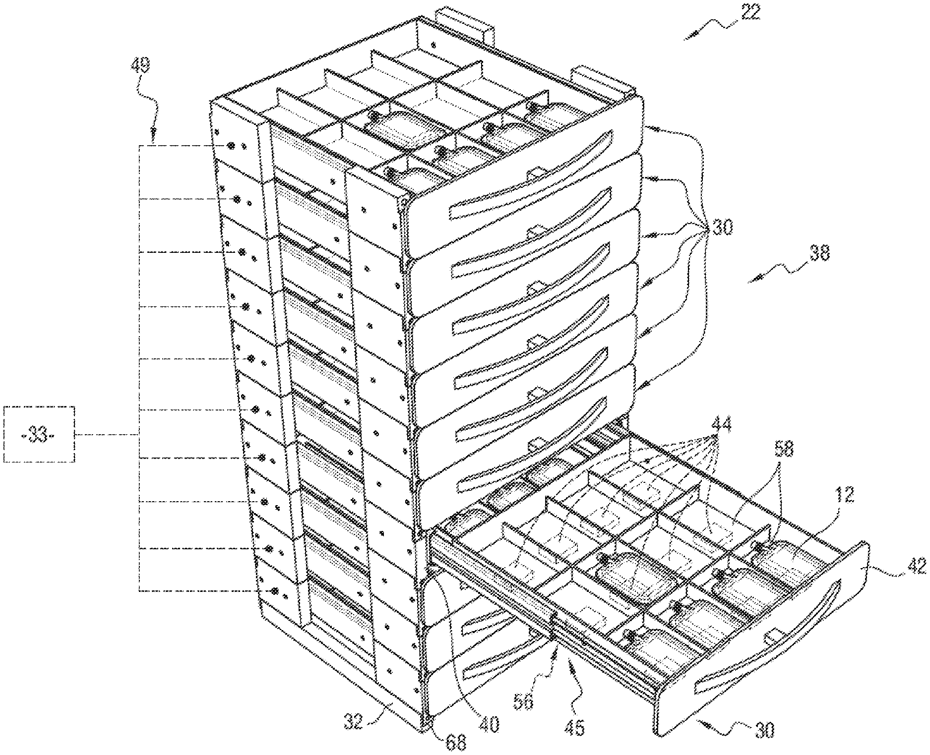
The device 22 comprises a plurality of drawer assemblies 30 and a base 32. As shown in FIG. 2, the device 22 further comprises a processing unit 33.
As described later, the drawer assemblies 30 are stacked on top of one another to form a vertical stack 38 of drawer assemblies 30. FIGS. 1 to 3 show an example of a stack of ten drawer assemblies 30.
Each drawer assembly 30 comprises a support 40, a drawer 42 and at least a second communication unit 44, visible in FIG. 2.
The support 40 comprises a housing 45, an upper end 46, a lower end 48 (visible in FIG. 3) and connections 49 (visible in FIG. 2). Optionally, each drawer assembly 30 also comprises a plate.
Each housing 45 is designed to receive the corresponding drawer 42.
The upper end 46 of each drawer assembly 30, visible in FIG. 3, and comprises at least a first assembly member 51. The first assembly members 51 are, for example, female connecting members.
The lower end 48 of each drawer assembly 30, visible in FIG. 3, comprises at least one second assembly member 52 that is complementary to the first assembly members 51. The second assembly members 52 are, for example, male assembly members.
In the example illustrated in FIG. 3, the first connecting members 51 are slots, while the second connecting members 52 are ribs that are complementary to the slots.
Thus, each drawer assembly 30 is assembled with at least one other drawer assembly 30 of the stack 38 by the first assembly member(s) 51 of the drawer assembly 30 and/or by the second one or two assembly member(s) 52 of the drawer assembly 30.
The connections 49 are, for example, electrical connections.
In the embodiment illustrated in FIGS. 1 to 3, the connections 49 of each drawer assembly 30 are connected, on the one hand, to the second communication units 44 of the drawer assembly 30, and, on the other hand, to the second communication units of the other drawer assemblies 30. In addition, the connections 49 are connected to the processing unit 33.
Each drawer 42 is positioned in the housing 45 of the support 40. Each drawer 42 is able to slide relative to the corresponding support 40.
Each drawer 42 comprises a bottom 56 defining at least one slot 58 to receive an element 12.
The bottom 56 of each drawer 42 consists of a material that may be traversed by radio waves emitted by the second communication unit 44 of the drawer assembly 30 of the drawer 42.
The material of the bottom 56 of each drawer 42 is, for example, plastic.
In the embodiment illustrated in FIGS. 1 to 3, the bottom 56 of each drawer 42 defines twelve slots 58 for receiving elements 12.
Each slot 58 is, for example, delimited by edges 59 to form a box 60.
In the embodiment illustrated in FIGS. 1 to 3, each drawer assembly 30 comprises as many second communication units 44 as there are slots 58.
Each second communication unit 44 is arranged below the bottom 56 of the drawer 42 in relation to the corresponding slot 58, in order to allow communication between the second communication unit 44 and the first communication unit 14 of an element 12 received in the slot 58. The expression "opposite" is understood to mean that each second communication unit 44 is arranged opposite the space delimited by the slot 58. In other words, the projection of the slot 58 in the plane of the second communication unit 44 is merged with the second communication unit 44.
Each second communication unit 44 is able to communicate, if necessary, with the first communication unit 14 of the element 12 received in the slot 58, in order to obtain information relating to the element 12.
Each second communication unit 44 is able to emit radio frequency waves. Each second communication unit 44 is designed to communicate with all the first communication units 14.
In an exemplary embodiment, the first communication units 14 are RFID tags, while the second communication units 44 are RFID readers.
More generally, each second communication unit 44 comprises at least one antenna, a memory, and, optionally, a microprocessor.
In the embodiment illustrated in FIGS. 1 to 3, each second communication unit 44 is integral with the drawer 42 of the corresponding drawer assembly 30. More specifically, each second communication unit 44 is fixed below the bottom 56 of the drawer 42 of the corresponding slot 58.
Alternatively, each second communication unit 44 is integral with the support 40 of the corresponding drawer assembly 30. Each drawer assembly 30 further includes a satellite. The satellite is a housing which contains the second communication unit 44. The satellite is fixed to the support 40 of the drawer assembly 30 directly under the drawer 42 of the drawer assembly 30. When the drawer 42 is closed, the second communication unit 44 is in a position facing the corresponding slot 58 and is therefore, if necessary, able to communicate with a first communication unit 14 positioned in the corresponding slot 58. When the drawer 42 is opened, the second communication unit 44 does not move with the drawer 42, and therefore is not able to communicate with a first communication unit 14 positioned in the corresponding slot 58.
Each plate is designed to prevent the passage of radio waves emitted by any second communication unit 44.
Each plate is positioned below the bottom 56 of the drawer 42 of each drawer assembly 30 and below the second communication units 44 corresponding to the slots 58 of the bottom 56 of the drawer 42 of the drawer assembly 30. Thus, each second communication unit 44 is only able to communicate with the first communication units 14 positioned above the second communication unit 44.
Each plate is, for example, made of metal.
The base 32 is assembled with the lowest drawer assembly 30 of the stack 38 of drawer assemblies 30. For this purpose, the base 32 comprises an upper end comprising at least a third assembly member 68. Each third assembly member 68 is identical to the first assembly member 51. The second assembly member(s) 52 of the last drawer assembly 30 of the stack 38 is/are assembled with the third assembly member(s) 68 of the base 32, which makes it possible to close the stack 38.
The processing unit 33 is able to process the information coming from the second communication units 44. In particular, the processing unit 33 is able to determine the occupation of each slot 58 and, where appropriate from the available information, the state of the element 12 positioned in the slot 58.
The states determined are, for example, two in number: a "valid" state and an "invalid" state. An element 12 is considered "valid" when the information relating to the element 12 conforms to a specification, or is otherwise considered "invalid".
Thus, the processing unit 33 has an instantaneous image of the storage device 22, namely which element 12 is in which slot 58 and the information relating to each of the elements 12. The processing unit 33 also comprises an input and output dates of each element 12 relative to the device 22.
In addition, the processing unit 33 is able to coordinate the second communication units 44. In particular, the processing unit 33 is able to activate each second communication unit 44 and to order, if necessary, the updating by the second communication unit 44 of the information contained in the first communication units 14.
Optionally, the processing unit 33 is able to trigger an alarm according to the occupation of each slot 58 and, if applicable, the state of the element 12 corresponding to the slot 58. For example, if the processing unit 33 determines that the same slot 58 comprises more than one element 12, the processing unit 33 triggers an alarm.
The operation of the device 22 integrated in the installation 10 will now be described.
When an element 12 is positioned in the slot 58 of one of the drawer assemblies 30 of the device 22, the second communication unit 44 corresponding to the slot 58, communicates with the first communication unit 14 of the element 12 in order to obtain information relating to the element 12. From the collected information, the processing unit 33 determines the state of each element 12, and, if necessary, either triggers an alarm or not.
Thus, the device 22 reliably controls the state of the elements 12 stored in the device 22, as well as the occupancy rate of the slots 58 of the drawer assemblies 30.
In addition, the specific positioning of the readers below the corresponding drawer offers a reduced footprint.
The device 22 is therefore an element storage device for reliably controlling the state of the elements 12 without encumbering the storage space.
In addition, it is easy to assemble and disassemble the drawer assemblies 30 of the device 22. Such modularity of the device 22 allows the device 22 to be adapted to suit a large number of installations 10 by modifying the number of drawer assemblies 30 in the stack 38.
In addition, a stack of drawer assemblies is much less heavy and cumbersome than a plurality of drawers, and is thus easier to handle and install.
In addition, from a manufacturing point of view, thousands of identical drawer assemblies are manufactured, rather than dozens of differently sized cabinets. This allows simplified stock management, and maintenance for economies of scale.
Furthermore, the device 22 may be adapted for an installation 10 that does not previously have RFID technology.
In addition, the reduced size makes it possible to envisage configurations in which the installation 10 contains a larger number of elements 12.
In addition, the installation 10 and/or the device 22 is/are easy to manufacture.
Finally, in the variant in which each drawer assembly 30 comprises a satellite, the satellite is in one assembly and is therefore easy to replace in the event of malfunction.
* * * * *
References
D00000
D00001
D00002
D00003
D00004
XML
uspto.report is an independent third-party trademark research tool that is not affiliated, endorsed, or sponsored by the United States Patent and Trademark Office (USPTO) or any other governmental organization. The information provided by uspto.report is based on publicly available data at the time of writing and is intended for informational purposes only.
While we strive to provide accurate and up-to-date information, we do not guarantee the accuracy, completeness, reliability, or suitability of the information displayed on this site. The use of this site is at your own risk. Any reliance you place on such information is therefore strictly at your own risk.
All official trademark data, including owner information, should be verified by visiting the official USPTO website at www.uspto.gov. This site is not intended to replace professional legal advice and should not be used as a substitute for consulting with a legal professional who is knowledgeable about trademark law.