Data processing device and data processing method
Ikegaya , et al. April 20, 2
U.S. patent number 10,985,782 [Application Number 16/459,088] was granted by the patent office on 2021-04-20 for data processing device and data processing method. This patent grant is currently assigned to SATURN LICENSING LLC. The grantee listed for this patent is SATURN LICENSING LLC. Invention is credited to Ryoji Ikegaya, Yuji Shinohara, Makiko Yamamoto.


View All Diagrams
| United States Patent | 10,985,782 |
| Ikegaya , et al. | April 20, 2021 |
Data processing device and data processing method
Abstract
The present technology relates to a data processing device and a data processing method which can ensure high communication quality in data transmission using LDPC codes. In group-wise interleaving, an LDPC code having a code length N of 64800 bits and a coding rate r of 11/15 is interleaved in a unit of a bit group of 360 bits. In group-wise deinterleaving, a sequence of bit groups of the LDPC code which has been subjected to the group-wise interleaving is returned to an original sequence. The present technology can be applied to, for example, a case in which data transmission is performed using LDPC codes.
| Inventors: | Ikegaya; Ryoji (Kanagawa, JP), Yamamoto; Makiko (Tokyo, JP), Shinohara; Yuji (Kanagawa, JP) | ||||||||||
|---|---|---|---|---|---|---|---|---|---|---|---|
| Applicant: |
|
||||||||||
| Assignee: | SATURN LICENSING LLC (New York,
NY) |
||||||||||
| Family ID: | 1000005502328 | ||||||||||
| Appl. No.: | 16/459,088 | ||||||||||
| Filed: | July 1, 2019 |
Prior Publication Data
| Document Identifier | Publication Date | |
|---|---|---|
| US 20190326936 A1 | Oct 24, 2019 | |
Related U.S. Patent Documents
| Application Number | Filing Date | Patent Number | Issue Date | ||
|---|---|---|---|---|---|
| 15993269 | May 30, 2018 | 10411741 | |||
| 15117782 | |||||
| PCT/JP2015/053184 | Feb 5, 2015 | ||||
Foreign Application Priority Data
| Feb 19, 2014 [JP] | 2014-030015 | |||
| Current U.S. Class: | 1/1 |
| Current CPC Class: | H03M 13/1177 (20130101); H03M 13/253 (20130101); H03M 13/2906 (20130101); H03M 13/616 (20130101); H03M 13/2792 (20130101); H03M 13/255 (20130101); H03M 13/116 (20130101); H03M 13/1165 (20130101); H03M 13/2778 (20130101); H03M 13/1185 (20130101); H03M 13/1111 (20130101); H04L 1/0071 (20130101); H03M 13/152 (20130101); H04L 2001/0093 (20130101); H04L 1/0057 (20130101) |
| Current International Class: | H03M 13/00 (20060101); H03M 13/25 (20060101); H03M 13/11 (20060101); H03M 13/29 (20060101); H03M 13/27 (20060101); H04L 1/00 (20060101); H03M 13/15 (20060101) |
References Cited [Referenced By]
U.S. Patent Documents
| 2007/0011570 | January 2007 | Jeong et al. |
| 2010/0275100 | October 2010 | Yokokawa et al. |
| 2011/0090948 | April 2011 | Zhou et al. |
| 2014/0082452 | March 2014 | Shinohara et al. |
| 2016/0233890 | August 2016 | Shinohara |
| 1 513 258 | Mar 2005 | EP | |||
| 2007-6494 | Jan 2007 | JP | |||
| 2011-523318 | Aug 2011 | JP | |||
| 2013-5124 | Jan 2013 | JP | |||
| 10-0619206 | Mar 2005 | KR | |||
| 10-2005-0025085 | Aug 2006 | KR | |||
Other References
|
"Digital Video Broadcasting (DVB); Second generation framing structure, channel coding and modulation systems for Broadcasting, Interactive Services, News Gathering and other broadband satellite applications (DVB-S2)," ETSI EN 302 307, V1.2.1, Aug. 2009, 78 pages. cited by applicant . "Digital Video Broadcasting (DVB); Frame structure channel coding and modulation for a second generation digital terrestrial television broadcasting system (DVB-T2)," ETSI EN 302 755, V1.3.1, Apr. 2012, 18 pages. cited by applicant . International Search Report dated Apr. 21, 2015 in PCT/JP2015/053184 filed Feb. 5, 2015. cited by applicant . Notice of Allowance dated May 26, 2017 in Korean Application No. 10-2016-7020549. cited by applicant . Notice of Allowance dated Mar. 22, 2017 in Korean Application No. 10-2016-7020549. cited by applicant . Notice of Allowance issued in corresponding Korean Application No. 10-2018-7035170 dated Jun. 11, 2019. cited by applicant. |
Primary Examiner: Blair; April Y
Assistant Examiner: Tang; Rong
Attorney, Agent or Firm: Oblon, McClelland, Maier & Neustadt, L.L.P.
Parent Case Text
CROSS REFERENCE TO RELATED APPLICATIONS
This application is a continuation of U.S. application Ser. No. 15/993,269, filed May 30, 2018, which is a continuation of U.S. application Ser. No. 15/117,782, filed Aug. 10, 2016, which is a National Stage application of PCT/JP2015/053184, filed Feb. 5, 2015 and claims the benefit of priority under 35 U.S.C. .sctn. 119 of Japanese Application No. 2014-030015, filed Feb. 19, 2014. The entire contents of each of the above-identified applications are incorporated herein by reference.
Claims
The invention claimed is:
1. A method comprising: low density parity check (LDPC) coding data to be transmitted in a digital broadcast signal by a transmitting device on the basis of a parity check matrix of an LDPC code having a code length N of 64800 bits and a coding rate r of 11/15 to generate an LDPC code word, wherein the LDPC code includes information bits and parity bits, the parity check matrix includes an information matrix portion corresponding to the information bits and a parity matrix portion corresponding to the parity bits, the information matrix portion is represented by a parity check matrix initial value table, and the parity check matrix initial value table, having each row indicating positions of elements "1" in corresponding 360 columns of the information matrix portion, includes the following, 696 989 1238 3091 3116 3738 4269 6406 7033 8048 9157 10254 12033 16456 16912 444 1488 6541 8626 10735 12447 13111 13706 14135 15195 15947 16453 16916 1713717268 401 460 992 1145 1576 1678 2238 2320 4280 6770 10027 12486 15363 16714 17157 1161 3108 3727 4508 5092 5348 5582 7727 11793 12515 12917 13362 14247 16717 17205 542 1190 6883 7911 8349 8835 10489 11631 14195 15009 15454 15482 16632 17040 17063 17 487 776 880 5077 6172 9771 11446 12798 16016 16109 16171 17087 17132 17226 1337 3275 3462 4229 9246 10180 10845 10866 12250 13633 14482 16024 16812 17186 17241 15 980 2305 3674 5971 8224 11499 11752 11770 12897 14082 14836 15311 16391 17209 0 3926 5869 8696 9351 9391 11371 14052 14172 14636 14974 16619 16961 17033 17237 3033 5317 6501 8579 10698 12168 12966 14019 15392 15806 15991 16493 16690 17062 17090 981 1205 4400 6410 11003 13319 13405 14695 15846 16297 16492 16563 16616 16862 16953 1725 4276 8869 9588 14062 14486 15474 15548 16300 16432 17042 17050 17060 17175 17273 1807 5921 9960 10011 14305 14490 14872 15852 16054 16061 16306 16799 16833 17136 17262 2826 4752 6017 6540 7016 8201 14245 14419 14716 15983 16569 16652 17171 17179 17247 1662 2516 3345 5229 8086 9686 11456 12210 14595 15808 16011 16421 16825 17112 17195 2890 4821 5987 7226 8823 9869 12468 14694 15352 15805 16075 16462 17102 17251 17263 3751 3890 4382 5720 10281 10411 11350 12721 13121 14127 14980 15202 15335 16735 17123 26 30 2805 5457 6630 7188 7477 7556 11065 16608 16859 16909 16943 17030 17103 40 4524 5043 5566 9645 10204 10282 11696 13080 14837 15607 16274 17034 17225 17266 904 3157 6284 7151 7984 11712 12887 13767 15547 16099 16753 16829 17044 17250 17259 7 311 4876 8334 9249 11267 14072 14559 15003 15235 15686 16331 17177 17238 17253 4410 8066 8596 9631 10369 11249 12610 15769 16791 16960 17018 17037 17062 17165 17204 24 8261 9691 10138 11607 12782 12786 13424 13933 15262 15795 16476 17084 17193 17220 88 11622 14705 15890 304 2026 2638 6018 1163 4268 11620 17232 9701 11785 14463 17260 4118 10952 12224 17006 3647 10823 11521 12060 1717 3753 9199 11642 2187 14280 17220 14787 16903 17061 381 3534 4294 3149 6947 8323 12562 16724 16881 7289 9997 15306 5615 13152 17260 5666 16926 17027 4190 7798 16831 4778 10629 17180 10001 13884 15453 6 2237 8203 7831 15144 15160 9186 17204 17243 9435 17168 17237 42 5701 17159 7812 14259 15715 39 4513 6658 38 9368 11273 1119 4785 17182 5620 16521 16729 16 6685 17242 210 3452 12383 466 14462 16250 10548 12633 13962 1452 6005 16453 22 4120 13684 5195 11563 16522 5518 16705 17201 12233 14552 15471 6067 13440 17248 8660 8967 17061 8673 12176 15051 5959 15767 16541 3244 12109 12414 31 15913 16323 3270 15686 16653 24 7346 14675 12 1531 8740 6228 7565 16667 16936 17122 17162 4868 8451 13183 3714 4451 16919 11313 13801 17132 17070 17191 17242 1911 11201 17186 14 17190 17254 11760 16008 16832 14543 17033 17278 16129 16765 17155 6891 15561 17007 12741 14744 17116 8992 16661 17277 1861 11130 16742 4822 13331 16192 13281 14027 14989 38 14887 17141 10698 13452 15674 4 2539 16877 857 17170 17249 11449 11906 12867 285 14118 16831 15191 17214 17242 39 728 16915 2469 12969 15579 16644 17151 17164 2592 8280 10448 9236 12431 17173 9064 16892 17233 4526 16146 17038 31 2116 16083 15837 16951 17031 5362 8382 16618 6137 13199 17221 2841 15068 17068 24 3620 17003 9880 15718 16764 1784 10240 17209 2731 10293 10846 3121 8723 16598 8563 15662 17088 13 1167 14676 29 13850 15963 3654 7553 8114 23 4362 14865 4434 14741 16688 8362 13901 17244 13687 16736 17232 46 4229 13394 13169 16383 16972 16031 16681 16952 3384 9894 12580 9841 14414 16165 5013 17099 17115 2130 8941 17266 6907 15428 17241 16 1860 17235 2151 16014 16643 14954 15958 17222 3969 8419 15116 31 15593 16984 11514 16605 17255; group-wise interleaving the LDPC code word in units of bit groups of 360 bits to generate a group-wise interleaved LDPC code word; wherein, in the group-wise interleaving, an (i+1)-th bit group from a head of the LDPC code word is indicated by a bit group i, and a sequence of bit groups 0 to 179 of the LDPC code word of 64800 bits is interleaved into a following sequence of bit groups 21, 11, 12, 9, 0, 6, 24, 25, 85, 103, 118, 122, 71, 101, 41, 93, 55, 73, 100, 40, 106, 119, 45, 80, 128, 68, 129, 61, 124, 36, 126, 117, 114, 132, 136, 140, 144, 148, 152, 156, 160, 164, 168, 172, 176, 20, 18, 10, 13, 16, 8, 26, 27, 54, 111, 52, 44, 87, 113, 115, 58, 116, 49, 77, 95, 86, 30, 78, 81, 56, 125, 53, 89, 94, 50, 123, 65, 83, 133, 137, 141, 145, 149, 153, 157, 161, 165, 169, 173, 177, 2, 17, 1, 4, 7, 15, 29, 82, 32, 102, 76, 121, 92, 130, 127, 62, 107, 38, 46, 43, 110, 75, 104, 70, 91, 69, 96, 120, 42, 34, 79, 35, 105, 134, 138, 142, 146, 150, 154, 158, 162, 166, 170, 174, 178, 19, 5, 3, 14, 22, 28, 23, 109, 51, 108, 131, 33, 84, 88, 64, 63, 59, 57, 97, 98, 48, 31, 99, 37, 72, 39, 74, 66, 60, 67, 47, 112, 90, 135, 139, 143, 147, 151, 155, 159, 163, 167, 171, 175, 179; mapping the group-wise interleaved LDPC code word to any one of 16 signal points which are determined by a modulation scheme in a unit of 4 bits; and transmitting the digital broadcast signal including the mapped group-wise interleaved LDPC code word, to a receiving device.
2. The method of claim 1, wherein the parity check matrix has no cycle-4.
3. The method of claim 1, wherein the modulation scheme employs non uniform constellations (NUCs).
4. A receiving device comprising: a receiver configured to receive a digital broadcast signal including a mapped group-wise interleaved low density parity check (LDPC) code word from a transmitting device; and at least one processor configured to process the mapped group-wise interleaved LDPC code word to obtain a group-wise interleaved LDPC code word, wherein each unit of 4 bits of the group-wise interleaved LDPC code word is mapped to one of 16 signal points of a modulation scheme, process the group-wise interleaved LDPC code word in units of bit groups of 360 bits to obtain an LDPC code word of a LDPC code, wherein an (i+1)-th bit group from a head of the LDPC code word of the LDPC code is indicated by a bit group i, the LDPC code word of the LDPC code has a sequence of bit groups 0 to 179, and the group-wise interleaved LDPC code word has a following sequence of bit groups, 21, 11, 12, 9, 0, 6, 24, 25, 85, 103, 118, 122, 71, 101, 41, 93, 55, 73, 100, 40, 106, 119, 45, 80, 128, 68, 129, 61, 124, 36, 126, 117, 114, 132, 136, 140, 144, 148, 152, 156, 160, 164, 168, 172, 176, 20, 18, 10, 13, 16, 8, 26, 27, 54, 111, 52, 44, 87, 113, 115, 58, 116, 49, 77, 95, 86, 30, 78, 81, 56, 125, 53, 89, 94, 50, 123, 65, 83, 133, 137, 141, 145, 149, 153, 157, 161, 165, 169, 173, 177, 2, 17, 1, 4, 7, 15, 29, 82, 32, 102, 76, 121, 92, 130, 127, 62, 107, 38, 46, 43, 110, 75, 104, 70, 91, 69, 96, 120, 42, 34, 79, 35, 105, 134, 138, 142, 146, 150, 154, 158, 162, 166, 170, 174, 178, 19, 5, 3, 14, 22, 28, 23, 109, 51, 108, 131, 33, 84, 88, 64, 63, 59, 57, 97, 98, 48, 31, 99, 37, 72, 39, 74, 66, 60, 67, 47, 112, 90, 135, 139, 143, 147, 151, 155, 159, 163, 167, 171, 175, 179; decode the LDPC code word of the LDPC code to obtain a decoded LDPC code word, and process the decoded LDPC code word for presentation of the digital broadcast signal; wherein the LDPC code has a code length N of 64800 bits and a coding rate r of 11/15 and is based on a parity check matrix initial value table listed as follows, 696 989 1238 3091 3116 3738 4269 6406 7033 8048 9157 10254 12033 16456 16912 444 1488 6541 8626 10735 12447 13111 13706 14135 15195 15947 16453 16916 17137 17268 401 460 992 1145 1576 1678 2238 2320 4280 6770 10027 12486 15363 16714 17157 1161 3108 3727 4508 5092 5348 5582 7727 11793 12515 12917 13362 14247 16717 17205 542 1190 6883 7911 8349 8835 10489 11631 14195 15009 15454 15482 16632 17040 17063 17 487 776 880 5077 6172 9771 11446 12798 16016 16109 16171 17087 17132 17226 1337 3275 3462 4229 9246 10180 10845 10866 12250 13633 14482 16024 16812 17186 17241 15 980 2305 3674 5971 8224 11499 11752 11770 12897 14082 14836 15311 16391 17209 0 3926 5869 8696 9351 9391 11371 14052 14172 14636 14974 16619 16961 17033 17237 3033 5317 6501 8579 10698 12168 12966 14019 15392 15806 15991 16493 16690 17062 17090 981 1205 4400 6410 11003 13319 13405 14695 15846 16297 16492 16563 16616 16862 16953 1725 4276 8869 9588 14062 14486 15474 15548 16300 16432 17042 17050 17060 17175 17273 1807 5921 9960 10011 14305 14490 14872 15852 16054 16061 16306 16799 16833 1713617262 2826 4752 6017 6540 7016 8201 14245 14419 14716 15983 16569 16652 17171 17179 17247 1662 2516 3345 5229 8086 9686 11456 12210 14595 15808 16011 16421 16825 17112 17195 2890 4821 5987 7226 8823 9869 12468 14694 15352 15805 16075 16462 17102 17251 17263 3751 3890 4382 5720 10281 10411 11350 12721 13121 14127 14980 15202 15335 16735 17123 26 30 2805 5457 6630 7188 7477 7556 11065 16608 16859 16909 16943 17030 17103 40 4524 5043 5566 9645 10204 10282 11696 13080 14837 15607 16274 17034 17225 17266 904 3157 6284 7151 7984 11712 12887 13767 15547 16099 16753 16829 17044 17250 17259 7 311 4876 8334 9249 11267 14072 14559 15003 15235 15686 16331 17177 17238 17253 4410 8066 8596 9631 10369 11249 12610 15769 16791 16960 17018 17037 17062 17165 17204 24 8261 9691 10138 11607 12782 12786 13424 13933 15262 15795 16476 17084 17193 17220 88 11622 14705 15890 304 2026 2638 6018 1163 4268 11620 17232 9701 11785 14463 17260 4118 10952 12224 17006 3647 10823 11521 12060 1717 3753 9199 11642 2187 14280 17220 14787 16903 17061 381 3534 4294 3149 6947 8323 12562 16724 16881 7289 9997 15306 5615 13152 17260 5666 16926 17027 4190 7798 16831 4778 10629 17180 10001 13884 15453 6 2237 8203 7831 15144 15160 9186 17204 17243 9435 17168 17237 42 5701 17159 7812 14259 15715 39 4513 6658 38 9368 11273 1119 4785 17182 5620 16521 16729 16 6685 17242 210 3452 12383 466 14462 16250 10548 12633 13962 1452 6005 16453 22 4120 13684 5195 11563 16522 5518 16705 17201 12233 1455215471 6067 13440 17248 8660 8967 17061 8673 12176 15051 5959 15767 16541 3244 12109 12414 31 15913 16323 3270 15686 16653 24 7346 14675 12 1531 8740 6228 7565 16667 16936 17122 17162 4868 8451 13183 3714 4451 16919 11313 13801 17132 17070 17191 17242 1911 11201 17186 14 17190 17254 11760 16008 16832 14543 1703317278 16129 16765 17155 6891 15561 17007 12741 14744 17116 8992 16661 17277 1861 11130 16742 4822 13331 16192 13281 14027 14989 38 14887 17141 10698 13452 15674 4 2539 16877 857 17170 17249 11449 11906 12867 285 14118 16831 15191 17214 17242 39 728 16915 2469 12969 15579 16644 17151 17164 2592 8280 10448 9236 12431 17173 9064 16892 17233 4526 16146 17038 31 2116 16083 15837 16951 17031 5362 8382 16618 6137 13199 17221 2841 15068 17068 24 3620 17003 9880 15718 16764 1784 10240 17209 2731 10293 10846 3121 8723 16598 8563 15662 17088 13 1167 14676 29 13850 15963 3654 7553 8114 23 4362 14865 4434 14741 16688 8362 13901 17244 13687 16736 17232 46 4229 13394 13169 16383 16972 16031 16681 16952 3384 9894 12580 9841 14414 16165 5013 17099 17115 2130 8941 17266 6907 15428 17241 16 1860 17235 2151 16014 16643 14954 15958 17222 3969 8419 15116 31 15593 16984 11514 16605 17255.
5. The receiving device of claim 4, wherein the LDPC code word of the LDPC code is encoded based on a parity check matrix of the LDPC code, the LDPC code word includes information bits and parity bits; the parity check matrix includes an information matrix part corresponding to the information bits and a parity matrix part corresponding to the parity bits, the information matrix part is represented by the parity check matrix initial value table, and each row of the parity check matrix initial value table indicates positions of elements "1" in corresponding 360 columns of the information matrix part corresponding to a subset of information bits used in calculating the parity bits.
6. The receiving device of claim 5, wherein a row of the parity check matrix initial value table is represented by i and a length of the parity bits of the LDPC code word of the LDPC code is represented by M, a 2+360.times.(i-1)-th column of the parity check matrix is obtained by a cyclic shift of a 1+360.times.(i-1)-th column of the parity check matrix downward by q=M/360.
7. The receiving device of claim 6, wherein for the 1+360.times.(i-1)-th column of the parity check matrix, an i-th row of the parity check matrix initial value table includes one or more values each representing a different row number of element 1 of the 1+360.times.(i-1)-th column of the parity check matrix, and for each column from the 2+360.times.(i-1)-th column to a 360.times.i-th column being a column other than the 1+360.times.(i-1)-th column of the parity check matrix, an i-th row and j-th column value of the parity check matrix initial value table is represented as Hi, j and a row number of a j-th element 1 of a w-th column of the parity check matrix H is represented as Hw-j, the row number Hw-j of the element 1 of the w-th column being a column other than the 1+360.times.(i-1)-th column of the parity check matrix is represented by the equation Hw-j=mod(Hi,j+mod((w-1),360).times.M/360,M).
8. The receiving device of claim 5, wherein the parity matrix part is a lower bidiagonal matrix, in which elements of "1" are arranged in a step-wise fashion.
9. The receiving device of claim 5, wherein the parity check matrix has no cycle-4.
10. The receiving device of claim 5, wherein the parity check matrix of the LDPC code belongs to an ensemble in which a performance threshold being a ratio of signal power to noise power at which a bit error rate starts to decrease is a predetermined value or smaller is found by multi-edge type density evolution.
11. A method comprising: receiving by a receiving device, a digital broadcast signal including a mapped group-wise interleaved low density parity check (LDPC) code word from a transmitting device; processing the mapped group-wise interleaved LDPC code word to obtain a group-wise interleaved LDPC code word, wherein each unit of 4 bits of the group-wise interleaved LDPC code word is mapped to one of 16 signal points of a modulation scheme; processing the group-wise interleaved LDPC code word in units of bit groups of 360 bits to obtain an LDPC code word of an LDPC code, wherein an (i+1)-th bit group from a head of the LDPC code word of the LDPC code is indicated by a bit group i, the LDPC code word of the LDPC code has a sequence of bit groups 0 to 179, and the group-wise interleaved LDPC code word has a following sequence of bit groups, 21, 11, 12, 9, 0, 6, 24, 25, 85, 103, 118, 122, 71, 101, 41, 93, 55, 73, 100, 40, 106, 119, 45, 80, 128, 68, 129, 61, 124, 36, 126, 117, 114, 132, 136, 140, 144, 148, 152, 156, 160, 164, 168, 172, 176, 20, 18, 10, 13, 16, 8, 26, 27, 54, 111, 52, 44, 87, 113, 115, 58, 116, 49, 77, 95, 86, 30, 78, 81, 56, 125, 53, 89, 94, 50, 123, 65, 83, 133, 137, 141, 145, 149, 153, 157, 161, 165, 169, 173, 177, 2, 17, 1, 4, 7, 15, 29, 82, 32, 102, 76, 121, 92, 130, 127, 62, 107, 38, 46, 43, 110, 75, 104, 70, 91, 69, 96, 120, 42, 34, 79, 35, 105, 134, 138, 142, 146, 150, 154, 158, 162, 166, 170, 174, 178, 19, 5, 3, 14, 22, 28, 23, 109, 51, 108, 131, 33, 84, 88, 64, 63, 59, 57, 97, 98, 48, 31, 99, 37, 72, 39, 74, 66, 60, 67, 47, 112, 90, 135, 139, 143, 147, 151, 155, 159, 163, 167, 171, 175, 179; decoding the LDPC code word of the LDPC code to obtain a decoded LDPC code word, and processing the decoded LDPC code word for presentation of the digital broadcast signal; wherein the LDPC code has a code length N of 64800 bits and a coding rate r of 11/15 and is based on a parity check matrix initial value table listed as follows, 696 989 1238 3091 3116 3738 4269 6406 7033 8048 9157 10254 12033 16456 16912 444 1488 6541 8626 10735 12447 13111 13706 14135 15195 15947 16453 16916 17137 17268 401 460 992 1145 1576 1678 2238 2320 4280 6770 10027 12486 15363 16714 17157 1161 3108 3727 4508 5092 5348 5582 7727 11793 12515 12917 13362 14247 16717 17205 542 1190 6883 7911 8349 8835 10489 11631 14195 15009 15454 15482 16632 17040 17063 17 487 776 880 5077 6172 9771 11446 12798 16016 16109 16171 17087 17132 17226 1337 3275 3462 4229 9246 10180 10845 10866 12250 13633 14482 16024 16812 17186 17241 15 980 2305 3674 5971 8224 11499 11752 11770 12897 14082 14836 15311 16391 17209 0 3926 5869 8696 9351 9391 11371 14052 14172 14636 14974 16619 16961 17033 17237 3033 5317 6501 8579 10698 12168 12966 14019 15392 15806 15991 16493 16690 17062 17090 981 1205 4400 6410 11003 13319 13405 14695 15846 16297 16492 16563 16616 16862 16953 1725 4276 8869 9588 14062 14486 15474 15548 16300 16432 17042 17050 17060 17175 17273 1807 5921 9960 10011 14305 14490 14872 15852 16054 16061 16306 16799 16833 1713617262 2826 4752 6017 6540 7016 8201 14245 14419 14716 15983 16569 16652 17171 17179 17247 1662 2516 3345 5229 8086 9686 11456 12210 14595 15808 16011 16421 16825 17112 17195 2890 4821 5987 7226 8823 9869 12468 14694 15352 15805 16075 16462 17102 17251 17263 3751 3890 4382 5720 10281 10411 11350 12721 13121 14127 14980 15202 15335 16735 17123 26 30 2805 5457 6630 7188 7477 7556 11065 16608 16859 16909 16943 17030 17103 40 4524 5043 5566 9645 10204 10282 11696 13080 14837 15607 16274 17034 17225 17266 904 3157 6284 7151 7984 11712 12887 13767 15547 16099 16753 16829 17044 17250 17259 7 311 4876 8334 9249 11267 14072 14559 15003 15235 15686 16331 17177 17238 17253 4410 8066 8596 9631 10369 11249 12610 15769 16791 16960 17018 17037 17062 17165 17204 24 8261 9691 10138 11607 12782 12786 13424 13933 15262 15795 16476 17084 17193 17220 88 11622 14705 15890 304 2026 2638 6018 1163 4268 11620 17232 9701 11785 14463 17260 4118 10952 12224 17006 3647 10823 11521 12060 1717 3753 9199 11642 2187 14280 17220 14787 16903 17061 381 3534 4294 3149 6947 8323 12562 16724 16881 7289 9997 15306 5615 13152 17260 5666 16926 17027 4190 7798 16831 4778 10629 17180 10001 13884 15453 6 2237 8203 7831 15144 15160 9186 17204 17243 9435 17168 17237 42 5701 17159 7812 14259 15715 39 4513 6658 38 9368 11273 1119 4785 17182 5620 16521 16729 16 6685 17242 210 3452 12383 466 14462 16250 10548 12633 13962 1452 6005 16453 22 4120 13684 5195 11563 16522 5518 16705 17201 12233 1455215471 6067 13440 17248 8660 8967 17061 8673 12176 15051 5959 15767 16541 3244 12109 12414 31 15913 16323 3270 15686 16653 24 7346 14675 12 1531 8740 6228 7565 16667 16936 17122 17162 4868 8451 13183 3714 4451 16919 11313 13801 17132 17070 17191 17242 1911 11201 17186 14 17190 17254 11760 16008 16832 14543 1703317278 16129 16765 17155 6891 15561 17007 12741 14744 17116 8992 16661 17277 1861 11130 16742 4822 13331 16192 13281 14027 14989 38 14887 17141 10698 13452 15674 4 2539 16877 857 17170 17249 11449 11906 12867 285 14118 16831 15191 17214 17242 39 728 16915 2469 12969 15579 16644 17151 17164 2592 8280 10448 9236 12431 17173 9064 16892 17233 4526 16146 17038 31 2116 16083 15837 16951 17031 5362 8382 16618 6137 13199 17221 2841 15068 17068 24 3620 17003 9880 15718 16764 1784 10240 17209 2731 10293 10846 3121 8723 16598 8563 15662 17088 13 1167 14676 29 13850 15963 3654 7553 8114 23 4362 14865 4434 14741 16688 8362 13901 17244 13687 16736 17232 46 4229 13394 13169 16383 16972 16031 16681 16952 3384 9894 12580 9841 14414 16165 5013 17099 17115 2130 8941 17266 6907 15428 17241 16 1860 17235 2151 16014 16643 14954 15958 17222 3969 8419 15116 31 15593 16984 11514 16605 17255.
12. The method of claim 11, wherein the LDPC code word of the LDPC code is encoded based on a parity check matrix of the LDPC code, the LDPC code word includes information bits and parity bits; the parity check matrix includes an information matrix part corresponding to the information bits and a parity matrix part corresponding to the parity bits, the information matrix part being represented by the parity check matrix initial value table, and each row of the parity check matrix initial value table indicates positions of elements "1" in corresponding 360 columns of the information matrix part corresponding to a subset of information bits used in calculating the parity bits.
13. The method of claim 12, wherein a row of the parity check matrix initial value table is represented by i and a length of the parity bits of the LDPC code word of the LDPC code is represented by M, a 2+360.times.(i-1)-th column of the parity check matrix is obtained by a cyclic shift of a 1+360.times.(i-1)-th column of the parity check matrix downward by q=M/360.
14. The method of claim 13, wherein for the 1+360.times.(i-1)-th column of the parity check matrix, an i-th row of the parity check matrix initial value table includes one or more values each representing a different row number of element 1 of the 1+360.times.(i-1)-th column of the parity check matrix, and for each column from the 2+360.times.(i-1)-th column to a 360.times.i-th column being a column other than the I+360.times.(i-1)-th column of the parity check matrix, an i-th row and j-th column value of the parity check matrix initial value table is represented as Hi, j and a row number of a j-th element 1 of a w-th column of the parity check matrix H is represented as Hw-j, the row number Hw-j of the element 1 of the w-th column being a column other than the 1+360.times.(i-1)-th column of the parity check matrix is represented by the equation Hw-j=mod(Hi,j+mod((w-1),360).times.M/360,M).
15. The method of claim 12, wherein the parity matrix part is a lower bidiagonal matrix, in which elements of "I" are arranged in a step-wise fashion.
16. The method of claim 12, wherein the parity check matrix has no cycle-4.
17. The method of claim 12, wherein the parity check matrix of the LDPC code belongs to an ensemble in which a performance threshold being a ratio of signal power to noise power at which a bit error rate starts to decrease is a predetermined value or smaller is found by multi-edge type density evolution.
18. The method of claim 11, wherein the modulation scheme employs non uniform constellations (NUCs).
19. A non-transitory computer readable medium including computer executable instructions which, when executed by a computer, cause the computer to perform a method comprising: receiving by a receiving device, a digital broadcast signal including a mapped group-wise interleaved low density parity check (LDPC) code word from a transmitting device; processing the mapped group-wise interleaved LDPC code word to obtain a group-wise interleaved LDPC code word, wherein each unit of 4 bits of the group-wise interleaved LDPC code word is mapped to one of 16 signal points of a modulation scheme; processing the group-wise interleaved LDPC code word in units of bit groups of 360 bits to obtain an LDPC code word of an LDPC code, wherein an (i+1)-th bit group from a head of the LDPC code word of the LDPC code is indicated by a bit group i, the LDPC code word of the LDPC code has a sequence of bit groups 0 to 179, and the group-wise interleaved LDPC code word has a following sequence of bit groups, 0, 14, 19, 21, 2, 11, 22, 9, 8, 7, 16, 3, 26, 24, 27, 80, 100, 121, 107, 31, 36, 42, 46, 49, 75, 93, 127, 95, 119, 73, 61, 63, 117, 89, 99, 129, 52, 111, 124, 48, 122, 82, 106, 91, 92, 71, 103, 102, 81, 113, 101, 97, 33, 115, 59, 112, 90, 51, 126, 85, 123, 40, 83, 53, 69, 70, 132, 134, 136, 138, 140, 142, 144, 146, 148, 150, 152, 154, 156, 158, 160, 162, 164, 166, 168, 170, 172, 174, 176, 178, 4, 5, 10, 12, 20, 6, 18, 13, 17, 15, 1, 29, 28, 23, 25, 67, 116, 66, 104, 44, 50, 47, 84, 76, 65, 130, 56, 128, 77, 39, 94, 87, 120, 62, 88, 74, 35, 110, 131, 98, 60, 37, 45, 78, 125, 41, 34, 118, 38, 72, 108, 58, 43, 109, 57, 105, 68, 86, 79, 96, 32, 114, 64, 55, 30, 54, 133, 135, 137, 139, 141, 143, 145, 147, 149, 151, 153, 155, 157, 159, 161, 163, 165, 167, 169, 171, 173, 175, 177, 179; decoding the LDPC code word of the LDPC code to obtain a decoded LDPC code word, and processing the decoded LDPC code word for presentation of the digital broadcast signal; wherein the LDPC code has a code length N of 64800 bits and a coding rate r of 11/15 and is based on a parity check matrix initial value table listed as follows, 696 989 1238 3091 3116 3738 4269 6406 7033 8048 9157 10254 12033 16456 16912 444 1488 6541 8626 10735 12447 13111 13706 14135 15195 15947 16453 16916 17137 17268 401 460 992 1145 1576 1678 2238 2320 4280 6770 10027 12486 15363 16714 17157 1161 3108 3727 4508 5092 5348 5582 7727 11793 12515 12917 13362 14247 16717 17205 542 1190 6883 7911 8349 8835 10489 11631 14195 15009 15454 15482 16632 17040 17063 17 487 776 880 5077 6172 9771 11446 12798 16016 16109 16171 17087 17132 17226 1337 3275 3462 4229 9246 10180 10845 10866 12250 13633 14482 16024 16812 1718617241 15 980 2305 3674 5971 8224 11499 11752 11770 12897 14082 14836 15311 16391 17209 0 3926 5869 8696 9351 9391 11371 14052 14172 14636 14974 16619 16961 17033 17237 3033 5317 6501 8579 10698 12168 12966 14019 15392 15806 15991 16493 16690 17062 17090 981 1205 4400 6410 11003 13319 13405 14695 15846 16297 16492 16563 16616 16862 16953 1725 4276 8869 9588 14062 14486 15474 15548 16300 16432 17042 17050 17060 17175 17273 1807 5921 9960 10011 14305 14490 14872 15852 16054 16061 16306 16799 16833 17136 17262 2826 4752 6017 6540 7016 8201 14245 14419 14716 15983 16569 16652 17171 17179 17247 1662 2516 3345 5229 8086 9686 11456 12210 14595 15808 16011 16421 16825 17112 17195 2890 4821 5987 7226 8823 9869 12468 14694 15352 15805 16075 16462 17102 17251 17263 3751 3890 4382 5720 10281 10411 11350 12721 13121 14127 14980 15202 15335 16735 17123 26 30 2805 5457 6630 7188 7477 7556 11065 16608 16859 16909 16943 17030 17103 40 4524 5043 5566 9645 10204 10282 11696 13080 14837 15607 16274 17034 17225 17266 904 3157 6284 7151 7984 11712 12887 13767 15547 16099 16753 16829 17044 17250 17259 7 311 4876 8334 9249 11267 14072 14559 15003 15235 15686 16331 17177 17238 17253 4410 8066 8596 9631 10369 11249 12610 15769 16791 16960 17018 17037 17062 17165 17204 24 8261 9691 10138 11607 12782 12786 13424 13933 15262 15795 16476 17084 17193 17220 88 11622 14705 15890 304 2026 2638 6018 1163 4268 11620 17232 9701 11785 14463 17260 4118 10952 12224 17006 3647 10823 11521 12060 1717 3753 9199 11642 2187 14280 17220 14787 16903 17061 381 3534 4294 3149 6947 8323 12562 16724 16881 7289 9997 15306 5615 13152 17260 5666 16926 17027 4190 7798 16831 4778 10629 17180 10001 13884 15453 6 2237 8203 7831 15144 15160 9186 17204 17243 9435 17168 17237 42 5701 17159 7812 14259 15715 39 4513 6658 38 9368 11273 1119 4785 17182 5620 16521 16729 16 6685 17242 210 3452 12383 466 14462 16250 10548 12633 13962 1452 6005 16453 22 4120 13684 5195 11563 16522 5518 16705 17201 12233 14552 15471 6067 13440 17248 8660 8967 17061 8673 12176 15051 5959 15767 16541 3244 12109 12414 31 15913 16323 3270 15686 16653 24 7346 14675 12 1531 8740 6228 7565 16667 16936 17122 17162 4868 8451 13183 3714 4451 16919 11313 13801 17132 17070 17191 17242 1911 11201 17186 14 17190 17254 11760 16008 16832 14543 17033 17278 16129 16765 17155 6891 15561 17007 12741 14744 17116 8992 16661 17277 1861 11130 16742 4822 13331 16192 13281 14027 14989 38 14887 17141 10698 13452 15674 4 2539 16877 857 17170 17249 11449 11906 12867 285 14118 16831 15191 17214 17242 39 728 16915 2469 12969 15579 16644 17151 17164 2592 8280 10448 9236 12431 17173 9064 16892 17233 4526 16146 17038 31 2116 16083 15837 16951 17031 5362 8382 16618 6137 13199 17221 2841 15068 17068 24 3620 17003 9880 15718 16764 1784 10240 17209 2731 10293 10846 3121 8723 16598 8563 15662 17088 13 1167 14676 29 13850 15963 3654 7553 8114 23 4362 14865 4434 14741 16688 8362 13901 17244 13687 16736 17232 46 4229 13394 13169 16383 16972 16031 16681 16952 3384 9894 12580 9841 14414 16165 5013 17099 17115 2130 8941 17266 6907 15428 17241 16 1860 17235 2151 16014 16643 14954 15958 17222 3969 8419 15116 31 15593 16984 11514 16605 17255.
20. The non-transitory computer readable medium of claim 19, wherein the modulation scheme employs non uniform constellations (NUCs).
Description
TECHNICAL FIELD
The present technology relates to a data processing device and a data processing method, and more particularly, to a data processing device and a data processing method which can ensure high communication quality in data transmission using, for example, an LDPC code.
BACKGROUND ART
Some of information used in the specification and the drawings is provided by Samsung Electronics Co., Ltd. (hereinafter, referred to as Samsung), LG Electronics Inc., NERC, and CRC/ETRI (which is clarified in the drawings).
A low density parity check (LDPC) code has a high error correction capability and has been widely adopted in transmission systems for digital broadcasting, for example, Digital Video Broadcasting (DVB)-S.2, DVB-T.2, and DVB-C.2 used in Europe, and Advanced Television Systems Committee (ATSC) 3.0 used in the U.S. (for example, see Non-Patent Document 1).
The recent study shows that the performance of an LDPC code becomes closer to a Shannon limit as the code length thereof becomes larger, similar to a turbo code. The LDPC code has the property that the shortest distance is proportional to the code length. Therefore, the LDPC code has the advantages that block error probability characteristics are excellent and a so-called error floor phenomenon which is observed in the decoding characteristics of, for example, a turbo code rarely occurs.
CITATION LIST
Non-Patent Document
Non-Patent Document 1: DVB-S.2: ETSI EN 302 307 V1.2.1 (2009-08)
SUMMARY OF THE INVENTION
Problems to be Solved by the Invention
In data transmission using LDPC codes, for example, an LDPC code serves as a symbol (changes to a symbol) of quadrature modulation (digital modulation), such as quadrature phase shift keying (QPSK), and the symbol is mapped to a signal point of the quadrature modulation and is transmitted.
The data transmission using LDPC codes has come into widespread use and there has been a demand for ensuring high communication (transmission) quality.
The present technology has been made in view of the above-mentioned problems and an objective of the present technology is to ensure high communication quality in data transmission using LDPC codes.
Solutions to Problems
A first data processing device/method according to the present technology includes: a coding unit/step that performs LDPC coding on the basis of a parity check matrix of an LDPC code having a code length N of 64800 bits and a coding rate r of 11/15; a group-wise interleaving unit/step that performs group-wise interleaving which interleaves the LDPC code in a unit of a bit group of 360 bits; and a mapping unit/step that maps the LDPC code to any one of four signal points which are determined by a modulation method in a unit of 2 bits. In the group-wise interleaving, an (i+1)-th bit group from a head of the LDPC code is set as a bit group i, an (i+1)-th bit group from a head of the LDPC code is set as a bit group i and a sequence of bit groups 0 to 179 of the 64800-bit LDPC code is interleaved into a sequence of the following bit groups.
0, 14, 19, 21, 2, 11, 22, 9, 8, 7, 16, 3, 26, 24, 27, 80, 100, 121, 107, 31, 36, 42, 46, 49, 75, 93, 127, 95, 119, 73, 61, 63, 117, 89, 99, 129, 52, 111, 124, 48, 122, 82, 106, 91, 92, 71, 103, 102, 81, 113, 101, 97, 33, 115, 59, 112, 90, 51, 126, 85, 123, 40, 83, 53, 69, 70, 132, 134, 136, 138, 140, 142, 144, 146, 148, 150, 152, 154, 156, 158, 160, 162, 164, 166, 168, 170, 172, 174, 176, 178, 4, 5, 10, 12, 20, 6, 18, 13, 17, 15, 1, 29, 28, 23, 25, 67, 116, 66, 104, 44, 50, 47, 84, 76, 65, 130, 56, 128, 77, 39, 94, 87, 120, 62, 88, 74, 35, 110, 131, 98, 60, 37, 45, 78, 125, 41, 34, 118, 38, 72, 108, 58, 43, 109, 57, 105, 68, 86, 79, 96, 32, 114, 64, 55, 30, 54, 133, 135, 137, 139, 141, 143, 145, 147, 149, 151, 153, 155, 157, 159, 161, 163, 165, 167, 169, 171, 173, 175, 177, 179
The LDPC code includes information bits and parity bits. The parity check matrix includes an information matrix portion corresponding to the information bits and a parity matrix portion corresponding to the parity bits. The information matrix portion is represented by a parity check matrix initial value table. The parity check matrix initial value table indicates positions of elements "1" in the information matrix portion for every 360 columns and includes the following.
696 989 1238 3091 3116 3738 4269 6406 7033 8048 9157 10254 12033 16456 16912
444 1488 6541 8626 10735 12447 13111 13706 14135 15195 15947 16453 16916 17137 17268
401 460 992 1145 1576 1678 2238 2320 4280 6770 10027 12486 15363 16714 17157
1161 3108 3727 4508 5092 5348 5582 7727 11793 12515 12917 13362 14247 16717 17205
542 1190 6883 7911 8349 8835 10489 11631 14195 15009 15454 15482 16632 17040 17063
17 487 776 880 5077 6172 9771 11446 12798 16016 16109 16171 17087 17132 17226 1337 3275 3462 4229 9246 10180 10845 10866 12250 13633 14482 16024 16812 17186 17241
15 980 2305 3674 5971 8224 11499 11752 11770 12897 14082 14836 15311 16391 17209
0 3926 5869 8696 9351 9391 11371 14052 14172 14636 14974 16619 16961 17033 17237
3033 5317 6501 8579 10698 12168 12966 14019 15392 15806 15991 16493 16690 17062 17090
981 1205 4400 6410 11003 13319 13405 14695 15846 16297 16492 16563 16616 16862 16953
1725 4276 8869 9588 14062 14486 15474 15548 16300 16432 17042 17050 17060 17175 17273
1807 5921 9960 10011 14305 14490 14872 15852 16054 16061 16306 16799 16833 17136 17262
2826 4752 6017 6540 7016 8201 14245 14419 14716 15983 16569 16652 17171 17179 17247
1662 2516 3345 5229 8086 9686 11456 12210 14595 15808 16011 16421 16825 17112 17195
2890 4821 5987 7226 8823 9869 12468 14694 15352 15805 16075 16462 17102 17251 17263
3751 3890 4382 5720 10281 10411 11350 12721 13121 14127 14980 15202 15335 16735 17123
26 30 2805 5457 6630 7188 7477 7556 11065 16608 16859 16909 16943 17030 17103 40 4524 5043 5566 9645 10204 10282 11696 13080 14837 15607 16274 17034 17225 17266
904 3157 6284 7151 7984 11712 12887 13767 15547 16099 16753 16829 17044 17250 17259
7 311 4876 8334 9249 11267 14072 14559 15003 15235 15686 16331 17177 17238 17253
4410 8066 8596 9631 10369 11249 12610 15769 16791 16960 17018 17037 17062 17165 17204
24 8261 9691 10138 11607 12782 12786 13424 13933 15262 15795 16476 17084 17193 17220
88 11622 14705 15890
304 2026 2638 6018
1163 4268 11620 17232
9701 11785 14463 17260
4118 10952 12224 17006
3647 10823 11521 12060
1717 3753 9199 11642
2187 14280 17220
14787 16903 17061
381 3534 4294
3149 6947 8323
12562 16724 16881
7289 9997 15306
5615 13152 17260
5666 16926 17027
4190 7798 16831
4778 10629 17180
10001 13884 15453
6 2237 8203
7831 15144 15160
9186 17204 17243
9435 17168 17237
42 5701 17159
7812 14259 15715
39 4513 6658
38 9368 11273
1119 4785 17182
5620 16521 16729
16 6685 17242
210 3452 12383
466 14462 16250
10548 12633 13962
1452 6005 16453
22 4120 13684
5195 11563 16522
5518 16705 17201
12233 14552 15471
6067 13440 17248
8660 8967 17061
8673 12176 15051
5959 15767 16541
3244 12109 12414
31 15913 16323
3270 15686 16653
24 7346 14675
12 1531 8740
6228 7565 16667
16936 17122 17162
4868 8451 13183
3714 4451 16919
11313 13801 17132
17070 17191 17242
1911 11201 17186
14 17190 17254
11760 16008 16832
14543 17033 17278
16129 16765 17155
6891 15561 17007
12741 14744 17116
8992 16661 17277
1861 11130 16742
4822 13331 16192
13281 14027 14989
38 14887 17141
10698 13452 15674
4 2539 16877
857 17170 17249
11449 11906 12867
285 14118 16831
15191 17214 17242
39 728 16915
2469 12969 15579
16644 17151 17164
2592 8280 10448
9236 12431 17173
9064 16892 17233
4526 16146 17038
31 2116 16083
15837 16951 17031
5362 8382 16618
6137 13199 17221
2841 15068 17068
24 3620 17003
9880 15718 16764
1784 10240 17209
2731 10293 10846
3121 8723 16598
8563 15662 17088
13 1167 14676
29 13850 15963
3654 7553 8114
23 4362 14865
4434 14741 16688
8362 13901 17244
13687 16736 17232
46 4229 13394
13169 16383 16972
16031 16681 16952
3384 9894 12580
9841 14414 16165
5013 17099 17115
2130 8941 17266
6907 15428 17241
16 1860 17235
2151 16014 16643
14954 15958 17222
3969 8419 15116
31 15593 16984
11514 16605 17255
In the first data processing device/method, the LDPC coding is performed on the basis of the parity check matrix of the LDPC code having a code length N of 64800 bits and a coding rate r of 11/15. The group-wise interleaving which interleaves the LDPC code in a unit of a bit group of 360 bits is performed. Then, the LDPC code is mapped to any one of four signal points which are determined by the modulation method in a unit of 2 bits. In the group-wise interleaving, the (i+1)-th bit group from the head of the LDPC code is set as the bit group i and a sequence of bit groups 0 to 179 of the 64800-bit LDPC code is interleaved into a sequence of the following bit groups.
0, 14, 19, 21, 2, 11, 22, 9, 8, 7, 16, 3, 26, 24, 27, 80, 100, 121, 107, 31, 36, 42, 46, 49, 75, 93, 127, 95, 119, 73, 61, 63, 117, 89, 99, 129, 52, 111, 124, 48, 122, 82, 106, 91, 92, 71, 103, 102, 81, 113, 101, 97, 33, 115, 59, 112, 90, 51, 126, 85, 123, 40, 83, 53, 69, 70, 132, 134, 136, 138, 140, 142, 144, 146, 148, 150, 152, 154, 156, 158, 160, 162, 164, 166, 168, 170, 172, 174, 176, 178, 4, 5, 10, 12, 20, 6, 18, 13, 17, 15, 1, 29, 28, 23, 25, 67, 116, 66, 104, 44, 50, 47, 84, 76, 65, 130, 56, 128, 77, 39, 94, 87, 120, 62, 88, 74, 35, 110, 131, 98, 60, 37, 45, 78, 125, 41, 34, 118, 38, 72, 108, 58, 43, 109, 57, 105, 68, 86, 79, 96, 32, 114, 64, 55, 30, 54, 133, 135, 137, 139, 141, 143, 145, 147, 149, 151, 153, 155, 157, 159, 161, 163, 165, 167, 169, 171, 173, 175, 177, 179
The LDPC code includes the information bits and the parity bits. The parity check matrix includes the information matrix portion corresponding to the information bits and the parity matrix portion corresponding to the parity bits. The information matrix portion is represented by the parity check matrix initial value table. The parity check matrix initial value table indicates the positions of the elements "1" in the information matrix portion for every 360 columns and includes the following.
696 989 1238 3091 3116 3738 4269 6406 7033 8048 9157 10254 12033 16456 16912
444 1488 6541 8626 10735 12447 13111 13706 14135 15195 15947 16453 16916 17137 17268
401 460 992 1145 1576 1678 2238 2320 4280 6770 10027 12486 15363 16714 17157
1161 3108 3727 4508 5092 5348 5582 7727 11793 12515 12917 13362 14247 16717 17205
542 1190 6883 7911 8349 8835 10489 11631 14195 15009 15454 15482 16632 17040 17063
17 487 776 880 5077 6172 9771 11446 12798 16016 16109 16171 17087 17132 17226 1337 3275 3462 4229 9246 10180 10845 10866 12250 13633 14482 16024 16812 17186 17241
15 980 2305 3674 5971 8224 11499 11752 11770 12897 14082 14836 15311 16391 17209
0 3926 5869 8696 9351 9391 11371 14052 14172 14636 14974 16619 16961 17033 17237
3033 5317 6501 8579 10698 12168 12966 14019 15392 15806 15991 16493 16690 17062 17090
981 1205 4400 6410 11003 13319 13405 14695 15846 16297 16492 16563 16616 16862 16953
1725 4276 8869 9588 14062 14486 15474 15548 16300 16432 17042 17050 17060 17175 17273
1807 5921 9960 10011 14305 14490 14872 15852 16054 16061 16306 16799 16833 17136 17262
2826 4752 6017 6540 7016 8201 14245 14419 14716 15983 16569 16652 17171 17179 17247
1662 2516 3345 5229 8086 9686 11456 12210 14595 15808 16011 16421 16825 17112 17195
2890 4821 5987 7226 8823 9869 12468 14694 15352 15805 16075 16462 17102 17251 17263
3751 3890 4382 5720 10281 10411 11350 12721 13121 14127 14980 15202 15335 16735 17123
26 30 2805 5457 6630 7188 7477 7556 11065 16608 16859 16909 16943 17030 17103 40 4524 5043 5566 9645 10204 10282 11696 13080 14837 15607 16274 17034 17225 17266
904 3157 6284 7151 7984 11712 12887 13767 15547 16099 16753 16829 17044 17250 17259
7 311 4876 8334 9249 11267 14072 14559 15003 15235 15686 16331 17177 17238 17253
4410 8066 8596 9631 10369 11249 12610 15769 16791 16960 17018 17037 17062 17165 17204
24 8261 9691 10138 11607 12782 12786 13424 13933 15262 15795 16476 17084 17193 17220
88 11622 14705 15890
304 2026 2638 6018
1163 4268 11620 17232
9701 11785 14463 17260
4118 10952 12224 17006
3647 10823 11521 12060
1717 3753 9199 11642
2187 14280 17220
14787 16903 17061
381 3534 4294
3149 6947 8323
12562 16724 16881
7289 9997 15306
5615 13152 17260
5666 16926 17027
4190 7798 16831
4778 10629 17180
10001 13884 15453
6 2237 8203
7831 15144 15160
9186 17204 17243
9435 17168 17237
42 5701 17159
7812 14259 15715
39 4513 6658
38 9368 11273
1119 4785 17182
5620 16521 16729
16 6685 17242
210 3452 12383
466 14462 16250
10548 12633 13962
1452 6005 16453
22 4120 13684
5195 11563 16522
5518 16705 17201
12233 14552 15471
6067 13440 17248
8660 8967 17061
8673 12176 15051
5959 15767 16541
3244 12109 12414
31 15913 16323
3270 15686 16653
24 7346 14675
12 1531 8740
6228 7565 16667
16936 17122 17162
4868 8451 13183
3714 4451 16919
11313 13801 17132
17070 17191 17242
1911 11201 17186
14 17190 17254
11760 16008 16832
14543 17033 17278
16129 16765 17155
6891 15561 17007
12741 14744 17116
8992 16661 17277
1861 11130 16742
4822 13331 16192
13281 14027 14989
38 14887 17141
10698 13452 15674
4 2539 16877
857 17170 17249
11449 11906 12867
285 14118 16831
15191 17214 17242
39 728 16915
2469 12969 15579
16644 17151 17164
2592 8280 10448
9236 12431 17173
9064 16892 17233
4526 16146 17038
31 2116 16083
15837 16951 17031
5362 8382 16618
6137 13199 17221
2841 15068 17068
24 3620 17003
9880 15718 16764
1784 10240 17209
2731 10293 10846
3121 8723 16598
8563 15662 17088
13 1167 14676
29 13850 15963
3654 7553 8114
23 4362 14865
4434 14741 16688
8362 13901 17244
13687 16736 17232
46 4229 13394
13169 16383 16972
16031 16681 16952
3384 9894 12580
9841 14414 16165
5013 17099 17115
2130 8941 17266
6907 15428 17241
16 1860 17235
2151 16014 16643
14954 15958 17222
3969 8419 15116
31 15593 16984
11514 16605 17255
A second data processing device/method according to the present technology includes: a group-wise deinterleaving unit/step that returns a sequence of an LDPC code, which has been subjected to group-wise interleaving and is obtained from data transmitted from a transmitting device, to an original sequence. The transmitting device includes: a coding unit that performs LDPC coding on the basis of a parity check matrix of the LDPC code having a code length N of 64800 bits and a coding rate r of 11/15; a group-wise interleaving unit that performs the group-wise interleaving which interleaves the LDPC code in a unit of a bit group of 360 bits; and a mapping unit that maps the LDPC code to any one of four signal points which are determined by a modulation method in a unit of 2 bits. In the group-wise interleaving, an (i+1)-th bit group from a head of the LDPC code is set as a bit group i and a sequence of bit groups 0 to 179 of the 64800-bit LDPC code is interleaved into a sequence of the following bit groups.
0, 14, 19, 21, 2, 11, 22, 9, 8, 7, 16, 3, 26, 24, 27, 80, 100, 121, 107, 31, 36, 42, 46, 49, 75, 93, 127, 95, 119, 73, 61, 63, 117, 89, 99, 129, 52, 111, 124, 48, 122, 82, 106, 91, 92, 71, 103, 102, 81, 113, 101, 97, 33, 115, 59, 112, 90, 51, 126, 85, 123, 40, 83, 53, 69, 70, 132, 134, 136, 138, 140, 142, 144, 146, 148, 150, 152, 154, 156, 158, 160, 162, 164, 166, 168, 170, 172, 174, 176, 178, 4, 5, 10, 12, 20, 6, 18, 13, 17, 15, 1, 29, 28, 23, 25, 67, 116, 66, 104, 44, 50, 47, 84, 76, 65, 130, 56, 128, 77, 39, 94, 87, 120, 62, 88, 74, 35, 110, 131, 98, 60, 37, 45, 78, 125, 41, 34, 118, 38, 72, 108, 58, 43, 109, 57, 105, 68, 86, 79, 96, 32, 114, 64, 55, 30, 54, 133, 135, 137, 139, 141, 143, 145, 147, 149, 151, 153, 155, 157, 159, 161, 163, 165, 167, 169, 171, 173, 175, 177, 179
The LDPC code includes information bits and parity bits. The parity check matrix includes an information matrix portion corresponding to the information bits and a parity matrix portion corresponding to the parity bits. The information matrix portion is represented by a parity check matrix initial value table. The parity check matrix initial value table indicates positions of elements "1" in the information matrix portion for every 360 columns and includes the following. 696 989 1238 3091 3116 3738 4269 6406 7033 8048 9157 10254 12033 16456 16912
444 1488 6541 8626 10735 12447 13111 13706 14135 15195 15947 16453 16916 17137 17268
401 460 992 1145 1576 1678 2238 2320 4280 6770 10027 12486 15363 16714 17157
1161 3108 3727 4508 5092 5348 5582 7727 11793 12515 12917 13362 14247 16717 17205
542 1190 6883 7911 8349 8835 10489 11631 14195 15009 15454 15482 16632 17040 17063
17 487 776 880 5077 6172 9771 11446 12798 16016 16109 16171 17087 17132 17226 1337 3275 3462 4229 9246 10180 10845 10866 12250 13633 14482 16024 16812 17186 17241
15 980 2305 3674 5971 8224 11499 11752 11770 12897 14082 14836 15311 16391 17209
0 3926 5869 8696 9351 9391 11371 14052 14172 14636 14974 16619 16961 17033 17237
3033 5317 6501 8579 10698 12168 12966 14019 15392 15806 15991 16493 16690 17062 17090
981 1205 4400 6410 11003 13319 13405 14695 15846 16297 16492 16563 16616 16862 16953
1725 4276 8869 9588 14062 14486 15474 15548 16300 16432 17042 17050 17060 17175 17273
1807 5921 9960 10011 14305 14490 14872 15852 16054 16061 16306 16799 16833 17136 17262
2826 4752 6017 6540 7016 8201 14245 14419 14716 15983 16569 16652 17171 17179 17247
1662 2516 3345 5229 8086 9686 11456 12210 14595 15808 16011 16421 16825 17112 17195
2890 4821 5987 7226 8823 9869 12468 14694 15352 15805 16075 16462 17102 17251 17263
3751 3890 4382 5720 10281 10411 11350 12721 13121 14127 14980 15202 15335 16735 17123
26 30 2805 5457 6630 7188 7477 7556 11065 16608 16859 16909 16943 17030 17103 40 4524 5043 5566 9645 10204 10282 11696 13080 14837 15607 16274 17034 17225 17266
904 3157 6284 7151 7984 11712 12887 13767 15547 16099 16753 16829 17044 17250 17259
7 311 4876 8334 9249 11267 14072 14559 15003 15235 15686 16331 17177 17238 17253
4410 8066 8596 9631 10369 11249 12610 15769 16791 16960 17018 17037 17062 17165 17204
24 8261 9691 10138 11607 12782 12786 13424 13933 15262 15795 16476 17084 17193 17220
88 11622 14705 15890
304 2026 2638 6018
1163 4268 11620 17232
9701 11785 14463 17260
4118 10952 12224 17006
3647 10823 11521 12060
1717 3753 9199 11642
2187 14280 17220
14787 16903 17061
381 3534 4294
3149 6947 8323
12562 16724 16881
7289 9997 15306
5615 13152 17260
5666 16926 17027
4190 7798 16831
4778 10629 17180
10001 13884 15453
6 2237 8203
7831 15144 15160
9186 17204 17243
9435 17168 17237
42 5701 17159
7812 14259 15715
39 4513 6658
38 9368 11273
1119 4785 17182
5620 16521 16729
16 6685 17242
210 3452 12383
466 14462 16250
10548 12633 13962
1452 6005 16453
22 4120 13684
5195 11563 16522
5518 16705 17201
12233 14552 15471
6067 13440 17248
8660 8967 17061
8673 12176 15051
5959 15767 16541
3244 12109 12414
31 15913 16323
3270 15686 16653
24 7346 14675
12 1531 8740
6228 7565 16667
16936 17122 17162
4868 8451 13183
3714 4451 16919
11313 13801 17132
17070 17191 17242
1911 11201 17186
14 17190 17254
11760 16008 16832
14543 17033 17278
16129 16765 17155
6891 15561 17007
12741 14744 17116
8992 16661 17277
1861 11130 16742
4822 13331 16192
13281 14027 14989
38 14887 17141
10698 13452 15674
4 2539 16877
857 17170 17249
11449 11906 12867
285 14118 16831
15191 17214 17242
39 728 16915
2469 12969 15579
16644 17151 17164
2592 8280 10448
9236 12431 17173
9064 16892 17233
4526 16146 17038
31 2116 16083
15837 16951 17031
5362 8382 16618
6137 13199 17221
2841 15068 17068
24 3620 17003
9880 15718 16764
1784 10240 17209
2731 10293 10846
3121 8723 16598
8563 15662 17088
13 1167 14676
29 13850 15963
3654 7553 8114
23 4362 14865
4434 14741 16688
8362 13901 17244
13687 16736 17232
46 4229 13394
13169 16383 16972
16031 16681 16952
3384 9894 12580
9841 14414 16165
5013 17099 17115
2130 8941 17266
6907 15428 17241
16 1860 17235
2151 16014 16643
14954 15958 17222
3969 8419 15116
31 15593 16984
11514 16605 17255
In the second data processing device/method, the transmitting device includes: the coding unit that performs LDPC coding on the basis of the parity check matrix of the LDPC code having a code length N of 64800 bits and a coding rate r of 11/15; the group-wise interleaving unit that performs the group-wise interleaving which interleaves the LDPC code in a unit of a bit group of 360 bits; and the mapping unit that maps the LDPC code to any one of four signal points which are determined by the modulation method in a unit of 2 bits. In the group-wise interleaving, the (i+1)-th bit group from the head of the LDPC code is set as the bit group i and a sequence of bit groups 0 to 179 of the 64800-bit LDPC code is interleaved into a sequence of the following bit groups.
0, 14, 19, 21, 2, 11, 22, 9, 8, 7, 16, 3, 26, 24, 27, 80, 100, 121, 107, 31, 36, 42, 46, 49, 75, 93, 127, 95, 119, 73, 61, 63, 117, 89, 99, 129, 52, 111, 124, 48, 122, 82, 106, 91, 92, 71, 103, 102, 81, 113, 101, 97, 33, 115, 59, 112, 90, 51, 126, 85, 123, 40, 83, 53, 69, 70, 132, 134, 136, 138, 140, 142, 144, 146, 148, 150, 152, 154, 156, 158, 160, 162, 164, 166, 168, 170, 172, 174, 176, 178, 4, 5, 10, 12, 20, 6, 18, 13, 17, 15, 1, 29, 28, 23, 25, 67, 116, 66, 104, 44, 50, 47, 84, 76, 65, 130, 56, 128, 77, 39, 94, 87, 120, 62, 88, 74, 35, 110, 131, 98, 60, 37, 45, 78, 125, 41, 34, 118, 38, 72, 108, 58, 43, 109, 57, 105, 68, 86, 79, 96, 32, 114, 64, 55, 30, 54, 133, 135, 137, 139, 141, 143, 145, 147, 149, 151, 153, 155, 157, 159, 161, 163, 165, 167, 169, 171, 173, 175, 177, 179
LDPC code includes the information bits and the parity bits. The parity check matrix includes the information matrix portion corresponding to the information bits and the parity matrix portion corresponding to the parity bits. The information matrix portion is represented by the parity check matrix initial value table. The parity check matrix initial value table indicates positions of elements "1" in the information matrix portion for every 360 columns and includes the following. A sequence of the bit groups of the LDPC code, which has been subjected to the group-wise interleaving and is obtained from the data transmitted from the transmitting device, is returned to the original sequence.
696 989 1238 3091 3116 3738 4269 6406 7033 8048 9157 10254 12033 16456 16912
88 6541 8626 10735 12447 13111 13706 14135 15195 15947 16453 16916 17137 17268
401 460 992 1145 1576 1678 2238 2320 4280 6770 10027 12486 15363 16714 17157
1161 3108 3727 4508 5092 5348 5582 7727 11793 12515 12917 13362 14247 16717 17205
542 1190 6883 7911 8349 8835 10489 11631 14195 15009 15454 15482 16632 17040 17063
17 487 776 880 5077 6172 9771 11446 12798 16016 16109 16171 17087 17132 17226 1337 3275 3462 4229 9246 10180 10845 10866 12250 13633 14482 16024 16812 17186 17241
15 980 2305 3674 5971 8224 11499 11752 11770 12897 14082 14836 15311 16391 17209
0 3926 5869 8696 9351 9391 11371 14052 14172 14636 14974 16619 16961 17033 17237
3033 5317 6501 8579 10698 12168 12966 14019 15392 15806 15991 16493 16690 17062 17090
981 1205 4400 6410 11003 13319 13405 14695 15846 16297 16492 16563 16616 16862 16953
1725 4276 8869 9588 14062 14486 15474 15548 16300 16432 17042 17050 17060 17175 17273
1807 5921 9960 10011 14305 14490 14872 15852 16054 16061 16306 16799 16833 17136 17262
2826 4752 6017 6540 7016 8201 14245 14419 14716 15983 16569 16652 17171 17179 17247
1662 2516 3345 5229 8086 9686 11456 12210 14595 15808 16011 16421 16825 17112 17195
2890 4821 5987 7226 8823 9869 12468 14694 15352 15805 16075 16462 17102 17251 17263
3751 3890 4382 5720 10281 10411 11350 12721 13121 14127 14980 15202 15335 16735 17123
26 30 2805 5457 6630 7188 7477 7556 11065 16608 16859 16909 16943 17030 17103 40 4524 5043 5566 9645 10204 10282 11696 13080 14837 15607 16274 17034 17225 17266
904 3157 6284 7151 7984 11712 12887 13767 15547 16099 16753 16829 17044 17250 17259
7 311 4876 8334 9249 11267 14072 14559 15003 15235 15686 16331 17177 17238 17253
4410 8066 8596 9631 10369 11249 12610 15769 16791 16960 17018 17037 17062 17165 17204
24 8261 9691 10138 11607 12782 12786 13424 13933 15262 15795 16476 17084 17193 17220
88 11622 14705 15890
304 2026 2638 6018
1163 4268 11620 17232
9701 11785 14463 17260
4118 10952 12224 17006
3647 10823 11521 12060
1717 3753 9199 11642
2187 14280 17220
14787 16903 17061
381 3534 4294
3149 6947 8323
12562 16724 16881
7289 9997 15306
5615 13152 17260
5666 16926 17027
4190 7798 16831
4778 10629 17180
10001 13884 15453
6 2237 8203
7831 15144 15160
9186 17204 17243
9435 17168 17237
42 5701 17159
7812 14259 15715
39 4513 6658
38 9368 11273
1119 4785 17182
5620 16521 16729
16 6685 17242
210 3452 12383
466 14462 16250
10548 12633 13962
1452 6005 16453
22 4120 13684
5195 11563 16522
5518 16705 17201
12233 14552 15471
6067 13440 17248
8660 8967 17061
8673 12176 15051
5959 15767 16541
3244 12109 12414
31 15913 16323
3270 15686 16653
24 7346 14675
12 1531 8740
6228 7565 16667
16936 17122 17162
4868 8451 13183
3714 4451 16919
11313 13801 17132
17070 17191 17242
1911 11201 17186
14 17190 17254
11760 16008 16832
14543 17033 17278
16129 16765 17155
6891 15561 17007
12741 14744 17116
8992 16661 17277
1861 11130 16742
4822 13331 16192
13281 14027 14989
38 14887 17141
10698 13452 15674
4 2539 16877
857 17170 17249
11449 11906 12867
285 14118 16831
15191 17214 17242
39 728 16915
2469 12969 15579
16644 17151 17164
2592 8280 10448
9236 12431 17173
9064 16892 17233
4526 16146 17038
31 2116 16083
15837 16951 17031
5362 8382 16618
6137 13199 17221
2841 15068 17068
24 3620 17003
9880 15718 16764
1784 10240 17209
2731 10293 10846
3121 8723 16598
8563 15662 17088
13 1167 14676
29 13850 15963
3654 7553 8114
23 4362 14865
4434 14741 16688
8362 13901 17244
13687 16736 17232
46 4229 13394
13169 16383 16972
16031 16681 16952
3384 9894 12580
9841 14414 16165
5013 17099 17115
2130 8941 17266
6907 15428 17241
16 1860 17235
2151 16014 16643
14954 15958 17222
3969 8419 15116
31 15593 16984
11514 16605 17255
A third data processing device/method according to the present technology includes: a coding unit/step that performs LDPC coding on the basis of a parity check matrix of an LDPC code having a code length N of 64800 bits and a coding rate r of 11/15; a group-wise interleaving unit/step that performs group-wise interleaving which interleaves the LDPC code in a unit of a bit group of 360 bits; and a mapping unit/step that maps the LDPC code to any one of 16 signal points which are determined by a modulation method in a unit of 4 bits. In the group-wise interleaving, an (i+1)-th bit group from a head of the LDPC code is set as a bit group i and a sequence of bit groups 0 to 179 of the 64800-bit LDPC code is interleaved into a sequence of the following bit groups.
21, 11, 12, 9, 0, 6, 24, 25, 85, 103, 118, 122, 71, 101, 41, 93, 55, 73, 100, 40, 106, 119, 45, 80, 128, 68, 129, 61, 124, 36, 126, 117, 114, 132, 136, 140, 144, 148, 152, 156, 160, 164, 168, 172, 176, 20, 18, 10, 13, 16, 8, 26, 27, 54, 111, 52, 44, 87, 113, 115, 58, 116, 49, 77, 95, 86, 30, 78, 81, 56, 125, 53, 89, 94, 50, 123, 65, 83, 133, 137, 141, 145, 149, 153, 157, 161, 165, 169, 173, 177, 2, 17, 1, 4, 7, 15, 29, 82, 32, 102, 76, 121, 92, 130, 127, 62, 107, 38, 46, 43, 110, 75, 104, 70, 91, 69, 96, 120, 42, 34, 79, 35, 105, 134, 138, 142, 146, 150, 154, 158, 162, 166, 170, 174, 178, 19, 5, 3, 14, 22, 28, 23, 109, 51, 108, 131, 33, 84, 88, 64, 63, 59, 57, 97, 98, 48, 31, 99, 37, 72, 39, 74, 66, 60, 67, 47, 112, 90, 135, 139, 143, 147, 151, 155, 159, 163, 167, 171, 175, 179
The LDPC code includes information bits and parity bits. The parity check matrix includes an information matrix portion corresponding to the information bits and a parity matrix portion corresponding to the parity bits. The information matrix portion is represented by a parity check matrix initial value table. The parity check matrix initial value table indicates positions of elements "1" in the information matrix portion for every 360 columns and includes the following.
696 989 1238 3091 3116 3738 4269 6406 7033 8048 9157 10254 12033 16456 16912
444 1488 6541 8626 10735 12447 13111 13706 14135 15195 15947 16453 16916 17137 17268
401 460 992 1145 1576 1678 2238 2320 4280 6770 10027 12486 15363 16714 17157
1161 3108 3727 4508 5092 5348 5582 7727 11793 12515 12917 13362 14247 16717 17205
542 1190 6883 7911 8349 8835 10489 11631 14195 15009 15454 15482 16632 17040 17063
17 487 776 880 5077 6172 9771 11446 12798 16016 16109 16171 17087 17132 17226 1337 3275 3462 4229 9246 10180 10845 10866 12250 13633 14482 16024 16812 17186 17241
15 980 2305 3674 5971 8224 11499 11752 11770 12897 14082 14836 15311 16391 17209
0 3926 5869 8696 9351 9391 11371 14052 14172 14636 14974 16619 16961 17033 17237
3033 5317 6501 8579 10698 12168 12966 14019 15392 15806 15991 16493 16690 17062 17090
981 1205 4400 6410 11003 13319 13405 14695 15846 16297 16492 16563 16616 16862 16953
1725 4276 8869 9588 14062 14486 15474 15548 16300 16432 17042 17050 17060 17175 17273
1807 5921 9960 10011 14305 14490 14872 15852 16054 16061 16306 16799 16833 17136 17262
2826 4752 6017 6540 7016 8201 14245 14419 14716 15983 16569 16652 17171 17179 17247
1662 2516 3345 5229 8086 9686 11456 12210 14595 15808 16011 16421 16825 17112 17195
2890 4821 5987 7226 8823 9869 12468 14694 15352 15805 16075 16462 17102 17251 17263
3751 3890 4382 5720 10281 10411 11350 12721 13121 14127 14980 15202 15335 16735 17123
26 30 2805 5457 6630 7188 7477 7556 11065 16608 16859 16909 16943 17030 17103 40 4524 5043 5566 9645 10204 10282 11696 13080 14837 15607 16274 17034 17225 17266
904 3157 6284 7151 7984 11712 12887 13767 15547 16099 16753 16829 17044 17250 17259
7 311 4876 8334 9249 11267 14072 14559 15003 15235 15686 16331 17177 17238 17253
4410 8066 8596 9631 10369 11249 12610 15769 16791 16960 17018 17037 17062 17165 17204
24 8261 9691 10138 11607 12782 12786 13424 13933 15262 15795 16476 17084 17193 17220
88 11622 14705 15890
304 2026 2638 6018
1163 4268 11620 17232
9701 11785 14463 17260
4118 10952 12224 17006
3647 10823 11521 12060
1717 3753 9199 11642
2187 14280 17220
14787 16903 17061
381 3534 4294
3149 6947 8323
12562 16724 16881
7289 9997 15306
5615 13152 17260
5666 16926 17027
4190 7798 16831
4778 10629 17180
10001 13884 15453
6 2237 8203
7831 15144 15160
9186 17204 17243
9435 17168 17237
42 5701 17159
7812 14259 15715
39 4513 6658
38 9368 11273
1119 4785 17182
5620 16521 16729
16 6685 17242
210 3452 12383
466 14462 16250
10548 12633 13962
1452 6005 16453
22 4120 13684
5195 11563 16522
5518 16705 17201
12233 14552 15471
6067 13440 17248
8660 8967 17061
8673 12176 15051
5959 15767 16541
3244 12109 12414
31 15913 16323
3270 15686 16653
24 7346 14675
12 1531 8740
6228 7565 16667
16936 17122 17162
4868 8451 13183
3714 4451 16919
11313 13801 17132
17070 17191 17242
1911 11201 17186
14 17190 17254
11760 16008 16832
14543 17033 17278
16129 16765 17155
6891 15561 17007
12741 14744 17116
8992 16661 17277
1861 11130 16742
4822 13331 16192
13281 14027 14989
38 14887 17141
10698 13452 15674
4 2539 16877
857 17170 17249
11449 11906 12867
285 14118 16831
15191 17214 17242
39 728 16915
2469 12969 15579
16644 17151 17164
2592 8280 10448
9236 12431 17173
9064 16892 17233
4526 16146 17038
31 2116 16083
15837 16951 17031
5362 8382 16618
6137 13199 17221
2841 15068 17068
24 3620 17003
9880 15718 16764
1784 10240 17209
2731 10293 10846
3121 8723 16598
8563 15662 17088
13 1167 14676
29 13850 15963
3654 7553 8114
23 4362 14865
4434 14741 16688
8362 13901 17244
13687 16736 17232
46 4229 13394
13169 16383 16972
16031 16681 16952
3384 9894 12580
9841 14414 16165
5013 17099 17115
2130 8941 17266
6907 15428 17241
16 1860 17235
2151 16014 16643
14954 15958 17222
3969 8419 15116
31 15593 16984
11514 16605 17255
In the third data processing device/method, the LDPC coding is performed on the basis of the parity check matrix of the LDPC code having a code length N of 64800 bits and a coding rate r of 11/15. The group-wise interleaving which interleaves the LDPC code in a unit of a bit group of 360 bits is performed. Then, the LDPC code is mapped to any one of 16 signal points which are determined by the modulation method in a unit of 4 bits. In the group-wise interleaving, the (i+1)-th bit group from the head of the LDPC code is set as the bit group i and a sequence of bit groups 0 to 179 of the 64800-bit LDPC code is interleaved into a sequence of the following bit groups.
21, 11, 12, 9, 0, 6, 24, 25, 85, 103, 118, 122, 71, 101, 41, 93, 55, 73, 100, 40, 106, 119, 45, 80, 128, 68, 129, 61, 124, 36, 126, 117, 114, 132, 136, 140, 144, 148, 152, 156, 160, 164, 168, 172, 176, 20, 18, 10, 13, 16, 8, 26, 27, 54, 111, 52, 44, 87, 113, 115, 58, 116, 49, 77, 95, 86, 30, 78, 81, 56, 125, 53, 89, 94, 50, 123, 65, 83, 133, 137, 141, 145, 149, 153, 157, 161, 165, 169, 173, 177, 2, 17, 1, 4, 7, 15, 29, 82, 32, 102, 76, 121, 92, 130, 127, 62, 107, 38, 46, 43, 110, 75, 104, 70, 91, 69, 96, 120, 42, 34, 79, 35, 105, 134, 138, 142, 146, 150, 154, 158, 162, 166, 170, 174, 178, 19, 5, 3, 14, 22, 28, 23, 109, 51, 108, 131, 33, 84, 88, 64, 63, 59, 57, 97, 98, 48, 31, 99, 37, 72, 39, 74, 66, 60, 67, 47, 112, 90, 135, 139, 143, 147, 151, 155, 159, 163, 167, 171, 175, 179
The LDPC code includes the information bits and the parity bits. The parity check matrix includes the information matrix portion corresponding to the information bits and the parity matrix portion corresponding to the parity bits. The information matrix portion is represented by the parity check matrix initial value table. The parity check matrix initial value table indicates the positions of the elements "1" in the information matrix portion for every 360 columns and includes the following.
696 989 1238 3091 3116 3738 4269 6406 7033 8048 9157 10254 12033 16456 16912
444 1488 6541 8626 10735 12447 13111 13706 14135 15195 15947 16453 16916 17137 17268
401 460 992 1145 1576 1678 2238 2320 4280 6770 10027 12486 15363 16714 17157
1161 3108 3727 4508 5092 5348 5582 7727 11793 12515 12917 13362 14247 16717 17205
542 1190 6883 7911 8349 8835 10489 11631 14195 15009 15454 15482 16632 17040 17063
17 487 776 880 5077 6172 9771 11446 12798 16016 16109 16171 17087 17132 17226 1337 3275 3462 4229 9246 10180 10845 10866 12250 13633 14482 16024 16812 17186 17241
15 980 2305 3674 5971 8224 11499 11752 11770 12897 14082 14836 15311 16391 17209
0 3926 5869 8696 9351 9391 11371 14052 14172 14636 14974 16619 16961 17033 17237
3033 5317 6501 8579 10698 12168 12966 14019 15392 15806 15991 16493 16690 17062 17090 981 1205 4400 6410 11003 13319 13405 14695 15846 16297 16492 16563 16616 16862 16953
1725 4276 8869 9588 14062 14486 15474 15548 16300 16432 17042 17050 17060 17175 17273
1807 5921 9960 10011 14305 14490 14872 15852 16054 16061 16306 16799 16833 17136 17262
2826 4752 6017 6540 7016 8201 14245 14419 14716 15983 16569 16652 17171 17179 17247
1662 2516 3345 5229 8086 9686 11456 12210 14595 15808 16011 16421 16825 17112 17195
2890 4821 5987 7226 8823 9869 12468 14694 15352 15805 16075 16462 17102 17251 17263
3751 3890 4382 5720 10281 10411 11350 12721 13121 14127 14980 15202 15335 16735 17123
26 30 2805 5457 6630 7188 7477 7556 11065 16608 16859 16909 16943 17030 17103 40 4524 5043 5566 9645 10204 10282 11696 13080 14837 15607 16274 17034 17225 17266
904 3157 6284 7151 7984 11712 12887 13767 15547 16099 16753 16829 17044 17250 17259
7 311 4876 8334 9249 11267 14072 14559 15003 15235 15686 16331 17177 17238 17253
4410 8066 8596 9631 10369 11249 12610 15769 16791 16960 17018 17037 17062 17165 17204
24 8261 9691 10138 11607 12782 12786 13424 13933 15262 15795 16476 17084 17193 17220
88 11622 14705 15890
304 2026 2638 6018
1163 4268 11620 17232
9701 11785 14463 17260
4118 10952 12224 17006
3647 10823 11521 12060
1717 3753 9199 11642
2187 14280 17220
14787 16903 17061
381 3534 4294
3149 6947 8323
12562 16724 16881
7289 9997 15306
5615 13152 17260
5666 16926 17027
4190 7798 16831
4778 10629 17180
10001 13884 15453
6 2237 8203
7831 15144 15160
9186 17204 17243
9435 17168 17237
42 5701 17159
7812 14259 15715
39 4513 6658
38 9368 11273
1119 4785 17182
5620 16521 16729
16 6685 17242
210 3452 12383
466 14462 16250
10548 12633 13962
1452 6005 16453
22 4120 13684
5195 11563 16522
5518 16705 17201
12233 14552 15471
6067 13440 17248
8660 8967 17061
8673 12176 15051
5959 15767 16541
3244 12109 12414
31 15913 16323
3270 15686 16653
24 7346 14675
12 1531 8740
6228 7565 16667
16936 17122 17162
4868 8451 13183
3714 4451 16919
11313 13801 17132
17070 17191 17242
1911 11201 17186
14 17190 17254
11760 16008 16832
14543 17033 17278
16129 16765 17155
6891 15561 17007
12741 14744 17116
8992 16661 17277
1861 11130 16742
4822 13331 16192
13281 14027 14989
38 14887 17141
10698 13452 15674
4 2539 16877
857 17170 17249
11449 11906 12867
285 14118 16831
15191 17214 17242
39 728 16915
2469 12969 15579
16644 17151 17164
2592 8280 10448
9236 12431 17173
9064 16892 17233
4526 16146 17038
31 2116 16083
15837 16951 17031
5362 8382 16618
6137 13199 17221
2841 15068 17068
24 3620 17003
9880 15718 16764
1784 10240 17209
2731 10293 10846
3121 8723 16598
8563 15662 17088
13 1167 14676
29 13850 15963
3654 7553 8114
23 4362 14865
4434 14741 16688
8362 13901 17244
13687 16736 17232
46 4229 13394
13169 16383 16972
16031 16681 16952
3384 9894 12580
9841 14414 16165
5013 17099 17115
2130 8941 17266
6907 15428 17241
16 1860 17235
2151 16014 16643
14954 15958 17222
3969 8419 15116
31 15593 16984
11514 16605 17255
A fourth data processing device/method to the present technology includes a group-wise deinterleaving unit/step that returns a sequence of an LDPC code, which has been subjected to group-wise interleaving and is obtained from data transmitted from a transmitting device, to an original sequence. The transmitting device includes: a coding unit that performs LDPC coding on the basis of a parity check matrix of the LDPC code having a code length N of 64800 bits and a coding rate r of 11/15; a group-wise interleaving unit that performs the group-wise interleaving which interleaves the LDPC code in a unit of a bit group of 360 bits; and a mapping unit that maps the LDPC code to any one of 16 signal points which are determined by a modulation method in a unit of 4 bits. In the group-wise interleaving, an (i+1)-th bit group from a head of the LDPC code is set as a bit group i and a sequence of bit groups 0 to 179 of the 64800-bit LDPC code is interleaved into a sequence of the following bit groups.
21, 11, 12, 9, 0, 6, 24, 25, 85, 103, 118, 122, 71, 101, 41, 93, 55, 73, 100, 40, 106, 119, 45, 80, 128, 68, 129, 61, 124, 36, 126, 117, 114, 132, 136, 140, 144, 148, 152, 156, 160, 164, 168, 172, 176, 20, 18, 10, 13, 16, 8, 26, 27, 54, 111, 52, 44, 87, 113, 115, 58, 116, 49, 77, 95, 86, 30, 78, 81, 56, 125, 53, 89, 94, 50, 123, 65, 83, 133, 137, 141, 145, 149, 153, 157, 161, 165, 169, 173, 177, 2, 17, 1, 4, 7, 15, 29, 82, 32, 102, 76, 121, 92, 130, 127, 62, 107, 38, 46, 43, 110, 75, 104, 70, 91, 69, 96, 120, 42, 34, 79, 35, 105, 134, 138, 142, 146, 150, 154, 158, 162, 166, 170, 174, 178, 19, 5, 3, 14, 22, 28, 23, 109, 51, 108, 131, 33, 84, 88, 64, 63, 59, 57, 97, 98, 48, 31, 99, 37, 72, 39, 74, 66, 60, 67, 47, 112, 90, 135, 139, 143, 147, 151, 155, 159, 163, 167, 171, 175, 179
The LDPC code includes information bits and parity bits. The parity check matrix includes an information matrix portion corresponding to the information bits and a parity matrix portion corresponding to the parity bits. The information matrix portion is represented by a parity check matrix initial value table. The parity check matrix initial value table indicates positions of elements "1" in the information matrix portion for every 360 columns and includes the following.
696 989 1238 3091 3116 3738 4269 6406 7033 8048 9157 10254 12033 16456 16912
444 1488 6541 8626 10735 12447 13111 13706 14135 15195 15947 16453 16916 17137 17268
401 460 992 1145 1576 1678 2238 2320 4280 6770 10027 12486 15363 16714 17157
1161 3108 3727 4508 5092 5348 5582 7727 11793 12515 12917 13362 14247 16717 17205
542 1190 6883 7911 8349 8835 10489 11631 14195 15009 15454 15482 16632 17040 17063
17 487 776 880 5077 6172 9771 11446 12798 16016 16109 16171 17087 17132 17226 1337 3275 3462 4229 9246 10180 10845 10866 12250 13633 14482 16024 16812 17186 17241
15 980 2305 3674 5971 8224 11499 11752 11770 12897 14082 14836 15311 16391 17209
0 3926 5869 8696 9351 9391 11371 14052 14172 14636 14974 16619 16961 17033 17237
3033 5317 6501 8579 10698 12168 12966 14019 15392 15806 15991 16493 16690 17062 17090
981 1205 4400 6410 11003 13319 13405 14695 15846 16297 16492 16563 16616 16862 16953
1725 4276 8869 9588 14062 14486 15474 15548 16300 16432 17042 17050 17060 17175 17273
1807 5921 9960 10011 14305 14490 14872 15852 16054 16061 16306 16799 16833 17136 17262
2826 4752 6017 6540 7016 8201 14245 14419 14716 15983 16569 16652 17171 17179 17247
1662 2516 3345 5229 8086 9686 11456 12210 14595 15808 16011 16421 16825 17112 17195
2890 4821 5987 7226 8823 9869 12468 14694 15352 15805 16075 16462 17102 17251 17263
3751 3890 4382 5720 10281 10411 11350 12721 13121 14127 14980 15202 15335 16735 17123
26 30 2805 5457 6630 7188 7477 7556 11065 16608 16859 16909 16943 17030 17103 40 4524 5043 5566 9645 10204 10282 11696 13080 14837 15607 16274 17034 17225 17266
904 3157 6284 7151 7984 11712 12887 13767 15547 16099 16753 16829 17044 17250 17259
7 311 4876 8334 9249 11267 14072 14559 15003 15235 15686 16331 17177 17238 17253
4410 8066 8596 9631 10369 11249 12610 15769 16791 16960 17018 17037 17062 17165 17204
24 8261 9691 10138 11607 12782 12786 13424 13933 15262 15795 16476 17084 17193 17220
88 11622 14705 15890
304 2026 2638 6018
1163 4268 11620 17232
9701 11785 14463 17260
4118 10952 12224 17006
3647 10823 11521 12060
1717 3753 9199 11642
2187 14280 17220
14787 16903 17061
381 3534 4294
3149 6947 8323
12562 16724 16881
7289 9997 15306
5615 13152 17260
5666 16926 17027
4190 7798 16831
4778 10629 17180
10001 13884 15453
6 2237 8203
7831 15144 15160
9186 17204 17243
9435 17168 17237
42 5701 17159
7812 14259 15715
39 4513 6658
38 9368 11273
1119 4785 17182
5620 16521 16729
16 6685 17242
210 3452 12383
466 14462 16250
10548 12633 13962
1452 6005 16453
22 4120 13684
5195 11563 16522
5518 16705 17201
12233 14552 15471
6067 13440 17248
8660 8967 17061
8673 12176 15051
5959 15767 16541
3244 12109 12414
31 15913 16323
3270 15686 16653
24 7346 14675
12 1531 8740
6228 7565 16667
16936 17122 17162
4868 8451 13183
3714 4451 16919
11313 13801 17132
17070 17191 17242
1911 11201 17186
14 17190 17254
11760 16008 16832
14543 17033 17278
16129 16765 17155
6891 15561 17007
12741 14744 17116
8992 16661 17277
1861 11130 16742
4822 13331 16192
13281 14027 14989
38 14887 17141
10698 13452 15674
4 2539 16877
857 17170 17249
11449 11906 12867
285 14118 16831
15191 17214 17242
39 728 16915
2469 12969 15579
16644 17151 17164
2592 8280 10448
9236 12431 17173
9064 16892 17233
4526 16146 17038
31 2116 16083
15837 16951 17031
5362 8382 16618
6137 13199 17221
2841 15068 17068
24 3620 17003
9880 15718 16764
1784 10240 17209
2731 10293 10846
3121 8723 16598
8563 15662 17088
13 1167 14676
29 13850 15963
3654 7553 8114
23 4362 14865
4434 14741 16688
8362 13901 17244
13687 16736 17232
46 4229 13394
13169 16383 16972
16031 16681 16952
3384 9894 12580
9841 14414 16165
5013 17099 17115
2130 8941 17266
6907 15428 17241
16 1860 17235
2151 16014 16643
14954 15958 17222
3969 8419 15116
31 15593 16984
11514 16605 17255
In the fourth data processing device/method, the transmitting device includes: the coding unit that performs LDPC coding on the basis of the parity check matrix of the LDPC code having a code length N of 64800 bits and a coding rate r of 11/15; the group-wise interleaving unit that performs the group-wise interleaving which interleaves the LDPC code in a unit of a bit group of 360 bits; and the mapping unit that maps the LDPC code to any one of 16 signal points which are determined by the modulation method in a unit of 4 bits. In the group-wise interleaving, the (i+1)-th bit group from the head of the LDPC code is set as the bit group i and a sequence of bit groups 0 to 179 of the 64800-bit LDPC code is interleaved into a sequence of the following bit groups.
21, 11, 12, 9, 0, 6, 24, 25, 85, 103, 118, 122, 71, 101, 41, 93, 55, 73, 100, 40, 106, 119, 45, 80, 128, 68, 129, 61, 124, 36, 126, 117, 114, 132, 136, 140, 144, 148, 152, 156, 160, 164, 168, 172, 176, 20, 18, 10, 13, 16, 8, 26, 27, 54, 111, 52, 44, 87, 113, 115, 58, 116, 49, 77, 95, 86, 30, 78, 81, 56, 125, 53, 89, 94, 50, 123, 65, 83, 133, 137, 141, 145, 149, 153, 157, 161, 165, 169, 173, 177, 2, 17, 1, 4, 7, 15, 29, 82, 32, 102, 76, 121, 92, 130, 127, 62, 107, 38, 46, 43, 110, 75, 104, 70, 91, 69, 96, 120, 42, 34, 79, 35, 105, 134, 138, 142, 146, 150, 154, 158, 162, 166, 170, 174, 178, 19, 5, 3, 14, 22, 28, 23, 109, 51, 108, 131, 33, 84, 88, 64, 63, 59, 57, 97, 98, 48, 31, 99, 37, 72, 39, 74, 66, 60, 67, 47, 112, 90, 135, 139, 143, 147, 151, 155, 159, 163, 167, 171, 175, 179
The LDPC code includes the information bits and the parity bits. The parity check matrix includes the information matrix portion corresponding to the information bits and the parity matrix portion corresponding to the parity bits. The information matrix portion is represented by the parity check matrix initial value table. The parity check matrix initial value table indicates positions of elements "1" in the information matrix portion for every 360 columns and includes the following. A sequence of the bit groups of the LDPC code, which has been subjected to the group-wise interleaving and is obtained from the data transmitted from the transmitting device, is returned to the original sequence.
696 989 1238 3091 3116 3738 4269 6406 7033 8048 9157 10254 12033 16456 16912
444 1488 6541 8626 10735 12447 13111 13706 14135 15195 15947 16453 16916 17137 17268
401 460 992 1145 1576 1678 2238 2320 4280 6770 10027 12486 15363 16714 17157
1161 3108 3727 4508 5092 5348 5582 7727 11793 12515 12917 13362 14247 16717 17205
542 1190 6883 7911 8349 8835 10489 11631 14195 15009 15454 15482 16632 17040 17063
17 487 776 880 5077 6172 9771 11446 12798 16016 16109 16171 17087 17132 17226 1337 3275 3462 4229 9246 10180 10845 10866 12250 13633 14482 16024 16812 17186 17241
15 980 2305 3674 5971 8224 11499 11752 11770 12897 14082 14836 15311 16391 17209
0 3926 5869 8696 9351 9391 11371 14052 14172 14636 14974 16619 16961 17033 17237
3033 5317 6501 8579 10698 12168 12966 14019 15392 15806 15991 16493 16690 17062 17090
981 1205 4400 6410 11003 13319 13405 14695 15846 16297 16492 16563 16616 16862 16953
1725 4276 8869 9588 14062 14486 15474 15548 16300 16432 17042 17050 17060 17175 17273
1807 5921 9960 10011 14305 14490 14872 15852 16054 16061 16306 16799 16833 17136 17262
2826 4752 6017 6540 7016 8201 14245 14419 14716 15983 16569 16652 17171 17179 17247
1662 2516 3345 5229 8086 9686 11456 12210 14595 15808 16011 16421 16825 17112 17195
2890 4821 5987 7226 8823 9869 12468 14694 15352 15805 16075 16462 17102 17251 17263
3751 3890 4382 5720 10281 10411 11350 12721 13121 14127 14980 15202 15335 16735 17123
26 30 2805 5457 6630 7188 7477 7556 11065 16608 16859 16909 16943 17030 17103 40 4524 5043 5566 9645 10204 10282 11696 13080 14837 15607 16274 17034 17225 17266
904 3157 6284 7151 7984 11712 12887 13767 15547 16099 16753 16829 17044 17250 17259
7 311 4876 8334 9249 11267 14072 14559 15003 15235 15686 16331 17177 17238 17253
4410 8066 8596 9631 10369 11249 12610 15769 16791 16960 17018 17037 17062 17165 17204
24 8261 9691 10138 11607 12782 12786 13424 13933 15262 15795 16476 17084 17193 17220
88 11622 14705 15890
304 2026 2638 6018
1163 4268 11620 17232
9701 11785 14463 17260
4118 10952 12224 17006
3647 10823 11521 12060
1717 3753 9199 11642
2187 14280 17220
14787 16903 17061
381 3534 4294
3149 6947 8323
12562 16724 16881
7289 9997 15306
5615 13152 17260
5666 16926 17027
4190 7798 16831
4778 10629 17180
10001 13884 15453
6 2237 8203
7831 15144 15160
9186 17204 17243
9435 17168 17237
42 5701 17159
7812 14259 15715
39 4513 6658
38 9368 11273
1119 4785 17182
5620 16521 16729
16 6685 17242
210 3452 12383
466 14462 16250
10548 12633 13962
1452 6005 16453
22 4120 13684
5195 11563 16522
5518 16705 17201
12233 14552 15471
6067 13440 17248
8660 8967 17061
8673 12176 15051
5959 15767 16541
3244 12109 12414
31 15913 16323
3270 15686 16653
24 7346 14675
12 1531 8740
6228 7565 16667
16936 17122 17162
4868 8451 13183
3714 4451 16919
11313 13801 17132
17070 17191 17242
1911 11201 17186
14 17190 17254
11760 16008 16832
14543 17033 17278
16129 16765 17155
6891 15561 17007
12741 14744 17116
8992 16661 17277
1861 11130 16742
4822 13331 16192
13281 14027 14989
38 14887 17141
10698 13452 15674
4 2539 16877
857 17170 17249
11449 11906 12867
285 14118 16831
15191 17214 17242
39 728 16915
2469 12969 15579
16644 17151 17164
2592 8280 10448
9236 12431 17173
9064 16892 17233
4526 16146 17038
31 2116 16083
15837 16951 17031
5362 8382 16618
6137 13199 17221
2841 15068 17068
24 3620 17003
9880 15718 16764
1784 10240 17209
2731 10293 10846
3121 8723 16598
8563 15662 17088
13 1167 14676
29 13850 15963
3654 7553 8114
23 4362 14865
4434 14741 16688
8362 13901 17244
13687 16736 17232
46 4229 13394
13169 16383 16972
16031 16681 16952
3384 9894 12580
9841 14414 16165
5013 17099 17115
2130 8941 17266
6907 15428 17241
16 1860 17235
2151 16014 16643
14954 15958 17222
3969 8419 15116
31 15593 16984
11514 16605 17255
A fifth data processing device/method according to the present technology includes: a coding unit/step that performs LDPC coding on the basis of a parity check matrix of an LDPC code having a code length N of 64800 bits and a coding rate r of 11/15; a group-wise interleaving unit/step that performs group-wise interleaving which interleaves the LDPC code in a unit of a bit group of 360 bits; and a mapping unit/step that maps the LDPC code to any one of 64 signal points which are determined by a modulation method in a unit of 6 bits. In the group-wise interleaving, an (i+1)-th bit group from a head of the LDPC code is set as a bit group i and a sequence of bit groups 0 to 179 of the 64800-bit LDPC code is interleaved into a sequence of the following bit groups.
12, 15, 2, 16, 27, 50, 35, 74, 38, 70, 108, 32, 112, 54, 30, 122, 72, 116, 36, 90, 49, 85, 132, 138, 144, 150, 156, 162, 168, 174, 0, 14, 9, 5, 23, 66, 68, 52, 96, 117, 84, 128, 100, 63, 60, 127, 81, 99, 53, 55, 103, 95, 133, 139, 145, 151, 157, 163, 169, 175, 10, 22, 13, 11, 28, 104, 37, 57, 115, 46, 65, 129, 107, 75, 119, 110, 31, 43, 97, 78, 125, 58, 134, 140, 146, 152, 158, 164, 170, 176, 4, 19, 6, 8, 24, 44, 101, 94, 118, 130, 69, 71, 83, 34, 86, 124, 48, 106, 89, 40, 102, 91, 135, 141, 147, 153, 159, 165, 171, 177, 3, 20, 7, 17, 25, 87, 41, 120, 47, 80, 59, 62, 88, 45, 56, 131, 61, 126, 113, 92, 51, 98, 136, 142, 148, 154, 160, 166, 172, 178, 21, 18, 1, 26, 29, 39, 73, 121, 105, 77, 42, 114, 93, 82, 111, 109, 67, 79, 123, 64, 76, 33, 137, 143, 149, 155, 161, 167, 173, 179
The LDPC code includes information bits and parity bits. The parity check matrix includes an information matrix portion corresponding to the information bits and a parity matrix portion corresponding to the parity bits. The information matrix portion is represented by a parity check matrix initial value table. The parity check matrix initial value table indicates positions of elements "1" in the information matrix portion for every 360 columns and includes the following.
696 989 1238 3091 3116 3738 4269 6406 7033 8048 9157 10254 12033 16456 16912
444 1488 6541 8626 10735 12447 13111 13706 14135 15195 15947 16453 16916 17137 17268
401 460 992 1145 1576 1678 2238 2320 4280 6770 10027 12486 15363 16714 17157
1161 3108 3727 4508 5092 5348 5582 7727 11793 12515 12917 13362 14247 16717 17205
542 1190 6883 7911 8349 8835 10489 11631 14195 15009 15454 15482 16632 17040 17063
17 487 776 880 5077 6172 9771 11446 12798 16016 16109 16171 17087 17132 17226 1337 3275 3462 4229 9246 10180 10845 10866 12250 13633 14482 16024 16812 17186 17241
15 980 2305 3674 5971 8224 11499 11752 11770 12897 14082 14836 15311 16391 17209
0 3926 5869 8696 9351 9391 11371 14052 14172 14636 14974 16619 16961 17033 17237
3033 5317 6501 8579 10698 12168 12966 14019 15392 15806 15991 16493 16690 17062 17090
981 1205 4400 6410 11003 13319 13405 14695 15846 16297 16492 16563 16616 16862 16953
1725 4276 8869 9588 14062 14486 15474 15548 16300 16432 17042 17050 17060 17175 17273
1807 5921 9960 10011 14305 14490 14872 15852 16054 16061 16306 16799 16833 17136 17262
2826 4752 6017 6540 7016 8201 14245 14419 14716 15983 16569 16652 17171 17179 17247
1662 2516 3345 5229 8086 9686 11456 12210 14595 15808 16011 16421 16825 17112 17195
2890 4821 5987 7226 8823 9869 12468 14694 15352 15805 16075 16462 17102 17251 17263
3751 3890 4382 5720 10281 10411 11350 12721 13121 14127 14980 15202 15335 16735 17123
26 30 2805 5457 6630 7188 7477 7556 11065 16608 16859 16909 16943 17030 17103 40 4524 5043 5566 9645 10204 10282 11696 13080 14837 15607 16274 17034 17225 17266
904 3157 6284 7151 7984 11712 12887 13767 15547 16099 16753 16829 17044 17250 17259
7 311 4876 8334 9249 11267 14072 14559 15003 15235 15686 16331 17177 17238 17253
4410 8066 8596 9631 10369 11249 12610 15769 16791 16960 17018 17037 17062 17165 17204
24 8261 9691 10138 11607 12782 12786 13424 13933 15262 15795 16476 17084 17193 17220
88 11622 14705 15890
304 2026 2638 6018
1163 4268 11620 17232
9701 11785 14463 17260
4118 10952 12224 17006
3647 10823 11521 12060
1717 3753 9199 11642
2187 14280 17220
14787 16903 17061
381 3534 4294
3149 6947 8323
12562 16724 16881
7289 9997 15306
5615 13152 17260
5666 16926 17027
4190 7798 16831
4778 10629 17180
10001 13884 15453
6 2237 8203
7831 15144 15160
9186 17204 17243
9435 17168 17237
42 5701 17159
7812 14259 15715
39 4513 6658
38 9368 11273
1119 4785 17182
5620 16521 16729
16 6685 17242
210 3452 12383
466 14462 16250
10548 12633 13962
1452 6005 16453
22 4120 13684
5195 11563 16522
5518 16705 17201
12233 14552 15471
6067 13440 17248
8660 8967 17061
8673 12176 15051
5959 15767 16541
3244 12109 12414
31 15913 16323
3270 15686 16653
24 7346 14675
12 1531 8740
6228 7565 16667
16936 17122 17162
4868 8451 13183
3714 4451 16919
11313 13801 17132
17070 17191 17242
1911 11201 17186
14 17190 17254
11760 16008 16832
14543 17033 17278
16129 16765 17155
6891 15561 17007
12741 14744 17116
8992 16661 17277
1861 11130 16742
4822 13331 16192
13281 14027 14989
38 14887 17141
10698 13452 15674
4 2539 16877
857 17170 17249
11449 11906 12867
285 14118 16831
15191 17214 17242
39 728 16915
2469 12969 15579
16644 17151 17164
2592 8280 10448
9236 12431 17173
9064 16892 17233
4526 16146 17038
31 2116 16083
15837 16951 17031
5362 8382 16618
6137 13199 17221
2841 15068 17068
24 3620 17003
9880 15718 16764
1784 10240 17209
2731 10293 10846
3121 8723 16598
8563 15662 17088
13 1167 14676
29 13850 15963
3654 7553 8114
23 4362 14865
4434 14741 16688
8362 13901 17244
13687 16736 17232
46 4229 13394
13169 16383 16972
16031 16681 16952
3384 9894 12580
9841 14414 16165
5013 17099 17115
2130 8941 17266
6907 15428 17241
16 1860 17235
2151 16014 16643
14954 15958 17222
3969 8419 15116
31 15593 16984
11514 16605 17255
In the fifth data processing device/method, the LDPC coding is performed on the basis of the parity check matrix of the LDPC code having a code length N of 64800 bits and a coding rate r of 11/15. The group-wise interleaving which interleaves the LDPC code in a unit of a bit group of 360 bits is performed. Then, the LDPC code is mapped to any one of 64 signal points which are determined by the modulation method in a unit of 6 bits. In the group-wise interleaving, the (i+1)-th bit group from the head of the LDPC code is set as the bit group i and a sequence of bit groups 0 to 179 of the 64800-bit LDPC code is interleaved into a sequence of the following bit groups.
12, 15, 2, 16, 27, 50, 35, 74, 38, 70, 108, 32, 112, 54, 30, 122, 72, 116, 36, 90, 49, 85, 132, 138, 144, 150, 156, 162, 168, 174, 0, 14, 9, 5, 23, 66, 68, 52, 96, 117, 84, 128, 100, 63, 60, 127, 81, 99, 53, 55, 103, 95, 133, 139, 145, 151, 157, 163, 169, 175, 10, 22, 13, 11, 28, 104, 37, 57, 115, 46, 65, 129, 107, 75, 119, 110, 31, 43, 97, 78, 125, 58, 134, 140, 146, 152, 158, 164, 170, 176, 4, 19, 6, 8, 24, 44, 101, 94, 118, 130, 69, 71, 83, 34, 86, 124, 48, 106, 89, 40, 102, 91, 135, 141, 147, 153, 159, 165, 171, 177, 3, 20, 7, 17, 25, 87, 41, 120, 47, 80, 59, 62, 88, 45, 56, 131, 61, 126, 113, 92, 51, 98, 136, 142, 148, 154, 160, 166, 172, 178, 21, 18, 1, 26, 29, 39, 73, 121, 105, 77, 42, 114, 93, 82, 111, 109, 67, 79, 123, 64, 76, 33, 137, 143, 149, 155, 161, 167, 173, 179
The LDPC code includes the information bits and the parity bits. The parity check matrix includes the information matrix portion corresponding to the information bits and the parity matrix portion corresponding to the parity bits. The information matrix portion is represented by the parity check matrix initial value table. The parity check matrix initial value table indicates the positions of the elements "1" in the information matrix portion for every 360 columns and includes the following.
696 989 1238 3091 3116 3738 4269 6406 7033 8048 9157 10254 12033 16456 16912
444 1488 6541 8626 10735 12447 13111 13706 14135 15195 15947 16453 16916 17137 17268
401 460 992 1145 1576 1678 2238 2320 4280 6770 10027 12486 15363 16714 17157
1161 3108 3727 4508 5092 5348 5582 7727 11793 12515 12917 13362 14247 16717 17205
542 1190 6883 7911 8349 8835 10489 11631 14195 15009 15454 15482 16632 17040 17063
17 487 776 880 5077 6172 9771 11446 12798 16016 16109 16171 17087 17132 17226 1337 3275 3462 4229 9246 10180 10845 10866 12250 13633 14482 16024 16812 17186 17241
15 980 2305 3674 5971 8224 11499 11752 11770 12897 14082 14836 15311 16391 17209
0 3926 5869 8696 9351 9391 11371 14052 14172 14636 14974 16619 16961 17033 17237
3033 5317 6501 8579 10698 12168 12966 14019 15392 15806 15991 16493 16690 17062 17090
981 1205 4400 6410 11003 13319 13405 14695 15846 16297 16492 16563 16616 16862 16953
1725 4276 8869 9588 14062 14486 15474 15548 16300 16432 17042 17050 17060 17175 17273
1807 5921 9960 10011 14305 14490 14872 15852 16054 16061 16306 16799 16833 17136 17262
2826 4752 6017 6540 7016 8201 14245 14419 14716 15983 16569 16652 17171 17179 17247
1662 2516 3345 5229 8086 9686 11456 12210 14595 15808 16011 16421 16825 17112 17195
2890 4821 5987 7226 8823 9869 12468 14694 15352 15805 16075 16462 17102 17251 17263
3751 3890 4382 5720 10281 10411 11350 12721 13121 14127 14980 15202 15335 16735 17123
26 30 2805 5457 6630 7188 7477 7556 11065 16608 16859 16909 16943 17030 17103 40 4524 5043 5566 9645 10204 10282 11696 13080 14837 15607 16274 17034 17225 17266
904 3157 6284 7151 7984 11712 12887 13767 15547 16099 16753 16829 17044 17250 17259
7 311 4876 8334 9249 11267 14072 14559 15003 15235 15686 16331 17177 17238 17253
4410 8066 8596 9631 10369 11249 12610 15769 16791 16960 17018 17037 17062 17165 17204
24 8261 9691 10138 11607 12782 12786 13424 13933 15262 15795 16476 17084 17193 17220
88 11622 14705 15890
304 2026 2638 6018
1163 4268 11620 17232
9701 11785 14463 17260
4118 10952 12224 17006
3647 10823 11521 12060
1717 3753 9199 11642
2187 14280 17220
14787 16903 17061
381 3534 4294
3149 6947 8323
12562 16724 16881
7289 9997 15306
5615 13152 17260
5666 16926 17027
4190 7798 16831
4778 10629 17180
10001 13884 15453
6 2237 8203
7831 15144 15160
9186 17204 17243
9435 17168 17237
42 5701 17159
7812 14259 15715
39 4513 6658
38 9368 11273
1119 4785 17182
5620 16521 16729
16 6685 17242
210 3452 12383
466 14462 16250
10548 12633 13962
1452 6005 16453
22 4120 13684
5195 11563 16522
5518 16705 17201
12233 14552 15471
6067 13440 17248
8660 8967 17061
8673 12176 15051
5959 15767 16541
3244 12109 12414
31 15913 16323
3270 15686 16653
24 7346 14675
12 1531 8740
6228 7565 16667
16936 17122 17162
4868 8451 13183
3714 4451 16919
11313 13801 17132
17070 17191 17242
1911 11201 17186
14 17190 17254
11760 16008 16832
14543 17033 17278
16129 16765 17155
6891 15561 17007
12741 14744 17116
8992 16661 17277
1861 11130 16742
4822 13331 16192
13281 14027 14989
38 14887 17141
10698 13452 15674
4 2539 16877
857 17170 17249
11449 11906 12867
285 14118 16831
15191 17214 17242
39 728 16915
2469 12969 15579
16644 17151 17164
2592 8280 10448
9236 12431 17173
9064 16892 17233
4526 16146 17038
31 2116 16083
15837 16951 17031
5362 8382 16618
6137 13199 17221
2841 15068 17068
24 3620 17003
9880 15718 16764
1784 10240 17209
2731 10293 10846
3121 8723 16598
8563 15662 17088
13 1167 14676
29 13850 15963
3654 7553 8114
23 4362 14865
4434 14741 16688
8362 13901 17244
13687 16736 17232
46 4229 13394
13169 16383 16972
16031 16681 16952
3384 9894 12580
9841 14414 16165
5013 17099 17115
2130 8941 17266
6907 15428 17241
16 1860 17235
2151 16014 16643
14954 15958 17222
3969 8419 15116
31 15593 16984
11514 16605 17255
A sixth data processing device/method according to the present technology includes a group-wise deinterleaving unit/step that returns a sequence of an LDPC code, which has been subjected to group-wise interleaving and is obtained from data transmitted from a transmitting device, to an original sequence. The transmitting device includes: a coding unit that performs LDPC coding on the basis of a parity check matrix of the LDPC code having a code length N of 64800 bits and a coding rate r of 11/15; a group-wise interleaving unit that performs the group-wise interleaving which interleaves the LDPC code in a unit of a bit group of 360 bits; and a mapping unit that maps the LDPC code to any one of 64 signal points which are determined by a modulation method in a unit of 6 bits. In the group-wise interleaving, an (i+1)-th bit group from a head of the LDPC code is set as a bit group i and a sequence of bit groups 0 to 179 of the 64800-bit LDPC code is interleaved into a sequence of the following bit groups.
12, 15, 2, 16, 27, 50, 35, 74, 38, 70, 108, 32, 112, 54, 30, 122, 72, 116, 36, 90, 49, 85, 132, 138, 144, 150, 156, 162, 168, 174, 0, 14, 9, 5, 23, 66, 68, 52, 96, 117, 84, 128, 100, 63, 60, 127, 81, 99, 53, 55, 103, 95, 133, 139, 145, 151, 157, 163, 169, 175, 10, 22, 13, 11, 28, 104, 37, 57, 115, 46, 65, 129, 107, 75, 119, 110, 31, 43, 97, 78, 125, 58, 134, 140, 146, 152, 158, 164, 170, 176, 4, 19, 6, 8, 24, 44, 101, 94, 118, 130, 69, 71, 83, 34, 86, 124, 48, 106, 89, 40, 102, 91, 135, 141, 147, 153, 159, 165, 171, 177, 3, 20, 7, 17, 25, 87, 41, 120, 47, 80, 59, 62, 88, 45, 56, 131, 61, 126, 113, 92, 51, 98, 136, 142, 148, 154, 160, 166, 172, 178, 21, 18, 1, 26, 29, 39, 73, 121, 105, 77, 42, 114, 93, 82, 111, 109, 67, 79, 123, 64, 76, 33, 137, 143, 149, 155, 161, 167, 173, 179
The LDPC code includes information bits and parity bits. The parity check matrix includes an information matrix portion corresponding to the information bits and a parity matrix portion corresponding to the parity bits. The information matrix portion is represented by a parity check matrix initial value table. The parity check matrix initial value table indicates positions of elements "1" in the information matrix portion for every 360 columns and includes the following.
696 989 1238 3091 3116 3738 4269 6406 7033 8048 9157 10254 12033 16456 16912
444 1488 6541 8626 10735 12447 13111 13706 14135 15195 15947 16453 16916 17137 17268
401 460 992 1145 1576 1678 2238 2320 4280 6770 10027 12486 15363 16714 17157
1161 3108 3727 4508 5092 5348 5582 7727 11793 12515 12917 13362 14247 16717 17205
542 1190 6883 7911 8349 8835 10489 11631 14195 15009 15454 15482 16632 17040 17063
17 487 776 880 5077 6172 9771 11446 12798 16016 16109 16171 17087 17132 17226 1337 3275 3462 4229 9246 10180 10845 10866 12250 13633 14482 16024 16812 17186 17241
15 980 2305 3674 5971 8224 11499 11752 11770 12897 14082 14836 15311 16391 17209
0 3926 5869 8696 9351 9391 11371 14052 14172 14636 14974 16619 16961 17033 17237
3033 5317 6501 8579 10698 12168 12966 14019 15392 15806 15991 16493 16690 17062 17090
981 1205 4400 6410 11003 13319 13405 14695 15846 16297 16492 16563 16616 16862 16953
1725 4276 8869 9588 14062 14486 15474 15548 16300 16432 17042 17050 17060 17175 17273
1807 5921 9960 10011 14305 14490 14872 15852 16054 16061 16306 16799 16833 17136 17262
2826 4752 6017 6540 7016 8201 14245 14419 14716 15983 16569 16652 17171 17179 17247
1662 2516 3345 5229 8086 9686 11456 12210 14595 15808 16011 16421 16825 17112 17195
2890 4821 5987 7226 8823 9869 12468 14694 15352 15805 16075 16462 17102 17251 17263
3751 3890 4382 5720 10281 10411 11350 12721 13121 14127 14980 15202 15335 16735 17123
26 30 2805 5457 6630 7188 7477 7556 11065 16608 16859 16909 16943 17030 17103 40 4524 5043 5566 9645 10204 10282 11696 13080 14837 15607 16274 17034 17225 17266
904 3157 6284 7151 7984 11712 12887 13767 15547 16099 16753 16829 17044 17250 17259
7 311 4876 8334 9249 11267 14072 14559 15003 15235 15686 16331 17177 17238 17253
4410 8066 8596 9631 10369 11249 12610 15769 16791 16960 17018 17037 17062 17165 17204
24 8261 9691 10138 11607 12782 12786 13424 13933 15262 15795 16476 17084 17193 17220
88 11622 14705 15890
304 2026 2638 6018
1163 4268 11620 17232
9701 11785 14463 17260
4118 10952 12224 17006
3647 10823 11521 12060
1717 3753 9199 11642
2187 14280 17220
14787 16903 17061
381 3534 4294
3149 6947 8323
12562 16724 16881
7289 9997 15306
5615 13152 17260
5666 16926 17027
4190 7798 16831
4778 10629 17180
10001 13884 15453
6 2237 8203
7831 15144 15160
9186 17204 17243
9435 17168 17237
42 5701 17159
7812 14259 15715
39 4513 6658
38 9368 11273
1119 4785 17182
5620 16521 16729
16 6685 17242
210 3452 12383
466 14462 16250
10548 12633 13962
1452 6005 16453
22 4120 13684
5195 11563 16522
5518 16705 17201
12233 14552 15471
6067 13440 17248
8660 8967 17061
8673 12176 15051
5959 15767 16541
3244 12109 12414
31 15913 16323
3270 15686 16653
24 7346 14675
12 1531 8740
6228 7565 16667
16936 17122 17162
4868 8451 13183
3714 4451 16919
11313 13801 17132
17070 17191 17242
1911 11201 17186
14 17190 17254
11760 16008 16832
14543 17033 17278
16129 16765 17155
6891 15561 17007
12741 14744 17116
8992 16661 17277
1861 11130 16742
4822 13331 16192
13281 14027 14989
38 14887 17141
10698 13452 15674
4 2539 16877
857 17170 17249
11449 11906 12867
285 14118 16831
15191 17214 17242
39 728 16915
2469 12969 15579
16644 17151 17164
2592 8280 10448
9236 12431 17173
9064 16892 17233
4526 16146 17038
31 2116 16083
15837 16951 17031
5362 8382 16618
6137 13199 17221
2841 15068 17068
24 3620 17003
9880 15718 16764
1784 10240 17209
2731 10293 10846
3121 8723 16598
8563 15662 17088
13 1167 14676
29 13850 15963
3654 7553 8114
23 4362 14865
4434 14741 16688
8362 13901 17244
13687 16736 17232
46 4229 13394
13169 16383 16972
16031 16681 16952
3384 9894 12580
9841 14414 16165
5013 17099 17115
2130 8941 17266
6907 15428 17241
16 1860 17235
2151 16014 16643
14954 15958 17222
3969 8419 15116
31 15593 16984
11514 16605 17255
In the sixth data processing device/method, the transmitting device includes: the coding unit that performs LDPC coding on the basis of the parity check matrix of the LDPC code having a code length N of 64800 bits and a coding rate r of 11/15; the group-wise interleaving unit that performs the group-wise interleaving which interleaves the LDPC code in a unit of a bit group of 360 bits; and the mapping unit that maps the LDPC code to any one of 64 signal points which are determined by the modulation method in a unit of 6 bits. In the group-wise interleaving, the (i+1)-th bit group from the head of the LDPC code is set as the bit group i and a sequence of bit groups 0 to 179 of the 64800-bit LDPC code is interleaved into a sequence of the following bit groups.
12, 15, 2, 16, 27, 50, 35, 74, 38, 70, 108, 32, 112, 54, 30, 122, 72, 116, 36, 90, 49, 85, 132, 138, 144, 150, 156, 162, 168, 174, 0, 14, 9, 5, 23, 66, 68, 52, 96, 117, 84, 128, 100, 63, 60, 127, 81, 99, 53, 55, 103, 95, 133, 139, 145, 151, 157, 163, 169, 175, 10, 22, 13, 11, 28, 104, 37, 57, 115, 46, 65, 129, 107, 75, 119, 110, 31, 43, 97, 78, 125, 58, 134, 140, 146, 152, 158, 164, 170, 176, 4, 19, 6, 8, 24, 44, 101, 94, 118, 130, 69, 71, 83, 34, 86, 124, 48, 106, 89, 40, 102, 91, 135, 141, 147, 153, 159, 165, 171, 177, 3, 20, 7, 17, 25, 87, 41, 120, 47, 80, 59, 62, 88, 45, 56, 131, 61, 126, 113, 92, 51, 98, 136, 142, 148, 154, 160, 166, 172, 178, 21, 18, 1, 26, 29, 39, 73, 121, 105, 77, 42, 114, 93, 82, 111, 109, 67, 79, 123, 64, 76, 33, 137, 143, 149, 155, 161, 167, 173, 179
The LDPC code includes the information bits and the parity bits. The parity check matrix includes the information matrix portion corresponding to the information bits and the parity matrix portion corresponding to the parity bits. The information matrix portion is represented by the parity check matrix initial value table. The parity check matrix initial value table indicates positions of elements "1" in the information matrix portion for every 360 columns and includes the following. A sequence of the bit groups of the LDPC code, which has been subjected to the group-wise interleaving and is obtained from the data transmitted from the transmitting device, is returned to the original sequence.
696 989 1238 3091 3116 3738 4269 6406 7033 8048 9157 10254 12033 16456 16912
444 1488 6541 8626 10735 12447 13111 13706 14135 15195 15947 16453 16916 17137 17268
401 460 992 1145 1576 1678 2238 2320 4280 6770 10027 12486 15363 16714 17157
1161 3108 3727 4508 5092 5348 5582 7727 11793 12515 12917 13362 14247 16717 17205
542 1190 6883 7911 8349 8835 10489 11631 14195 15009 15454 15482 16632 17040 17063
17 487 776 880 5077 6172 9771 11446 12798 16016 16109 16171 17087 17132 17226 1337 3275 3462 4229 9246 10180 10845 10866 12250 13633 14482 16024 16812 17186 17241
15 980 2305 3674 5971 8224 11499 11752 11770 12897 14082 14836 15311 16391 17209
0 3926 5869 8696 9351 9391 11371 14052 14172 14636 14974 16619 16961 17033 17237
3033 5317 6501 8579 10698 12168 12966 14019 15392 15806 15991 16493 16690 17062 17090
981 1205 4400 6410 11003 13319 13405 14695 15846 16297 16492 16563 16616 16862 16953
1725 4276 8869 9588 14062 14486 15474 15548 16300 16432 17042 17050 17060 17175 17273
1807 5921 9960 10011 14305 14490 14872 15852 16054 16061 16306 16799 16833 17136 17262
2826 4752 6017 6540 7016 8201 14245 14419 14716 15983 16569 16652 17171 17179 17247
1662 2516 3345 5229 8086 9686 11456 12210 14595 15808 16011 16421 16825 17112 17195
2890 4821 5987 7226 8823 9869 12468 14694 15352 15805 16075 16462 17102 17251 17263
3751 3890 4382 5720 10281 10411 11350 12721 13121 14127 14980 15202 15335 16735 17123
26 30 2805 5457 6630 7188 7477 7556 11065 16608 16859 16909 16943 17030 17103 40 4524 5043 5566 9645 10204 10282 11696 13080 14837 15607 16274 17034 17225 17266
904 3157 6284 7151 7984 11712 12887 13767 15547 16099 16753 16829 17044 17250 17259
7 311 4876 8334 9249 11267 14072 14559 15003 15235 15686 16331 17177 17238 17253
4410 8066 8596 9631 10369 11249 12610 15769 16791 16960 17018 17037 17062 17165 17204
24 8261 9691 10138 11607 12782 12786 13424 13933 15262 15795 16476 17084 17193 17220
88 11622 14705 15890
304 2026 2638 6018
1163 4268 11620 17232
9701 11785 14463 17260
4118 10952 12224 17006
3647 10823 11521 12060
1717 3753 9199 11642
2187 14280 17220
14787 16903 17061
381 3534 4294
3149 6947 8323
12562 16724 16881
7289 9997 15306
5615 13152 17260
5666 16926 17027
4190 7798 16831
4778 10629 17180
10001 13884 15453
6 2237 8203
7831 15144 15160
9186 17204 17243
9435 17168 17237
42 5701 17159
7812 14259 15715
39 4513 6658
38 9368 11273
1119 4785 17182
5620 16521 16729
16 6685 17242
210 3452 12383
466 14462 16250
10548 12633 13962
1452 6005 16453
22 4120 13684
5195 11563 16522
5518 16705 17201
12233 14552 15471
6067 13440 17248
8660 8967 17061
8673 12176 15051
5959 15767 16541
3244 12109 12414
31 15913 16323
3270 15686 16653
24 7346 14675
12 1531 8740
6228 7565 16667
16936 17122 17162
4868 8451 13183
3714 4451 16919
11313 13801 17132
17070 17191 17242
1911 11201 17186
14 17190 17254
11760 16008 16832
14543 17033 17278
16129 16765 17155
6891 15561 17007
12741 14744 17116
8992 16661 17277
1861 11130 16742
4822 13331 16192
13281 14027 14989
38 14887 17141
10698 13452 15674
4 2539 16877
857 17170 17249
11449 11906 12867
285 14118 16831
15191 17214 17242
39 728 16915
2469 12969 15579
16644 17151 17164
2592 8280 10448
9236 12431 17173
9064 16892 17233
4526 16146 17038
31 2116 16083
15837 16951 17031
5362 8382 16618
6137 13199 17221
2841 15068 17068
24 3620 17003
9880 15718 16764
1784 10240 17209
2731 10293 10846
3121 8723 16598
8563 15662 17088
13 1167 14676
29 13850 15963
3654 7553 8114
23 4362 14865
4434 14741 16688
8362 13901 17244
13687 16736 17232
46 4229 13394
13169 16383 16972
16031 16681 16952
3384 9894 12580
9841 14414 16165
5013 17099 17115
2130 8941 17266
6907 15428 17241
16 1860 17235
2151 16014 16643
14954 15958 17222
3969 8419 15116
31 15593 16984
11514 16605 17255
The data processing device may be an independent device or an internal block forming one device.
Effects of the Invention
According to the present technology, it is possible to ensure high communication quality in data transmission using LDPC codes.
The effects described herein are not necessarily limited and may be any effect described in the present disclosure.
BRIEF DESCRIPTION OF DRAWINGS
FIG. 1 is a diagram illustrating a parity check matrix H of an LDPC code.
FIG. 2 is a flowchart illustrating an LDPC code decoding process.
FIG. 3 is a diagram illustrating an example of a parity check matrix of an LDPC code.
FIG. 4 is a diagram illustrating an example of a Tanner graph of the parity check matrix.
FIG. 5 is a diagram illustrating an example of a variable node.
FIG. 6 is a diagram illustrating an example of a check node.
FIG. 7 is a diagram illustrating an example of the structure of an embodiment of a transmission system to which the present technology is applied.
FIG. 8 is a block diagram illustrating an example of the structure of a transmitting device 11.
FIG. 9 is a block diagram illustrating an example of the structure of a bit interleaver 116.
FIG. 10 is a diagram illustrating an example of a parity check matrix.
FIG. 11 is a diagram illustrating an example of a parity matrix.
FIG. 12 is a diagram illustrating a parity check matrix of an LDPC code defined by a DVB-T.2 standard.
FIG. 13 is a diagram illustrating the parity check matrix of the LDPC code defined by the DVB-T.2 standard.
FIG. 14 is a diagram illustrating an example of a Tanner graph for the decoding of an LDPC code.
FIG. 15 is a diagram illustrating an example of a parity matrix H.sub.T having a dual diagonal structure and a Tanner graph corresponding to the parity matrix H.sub.T.
FIG. 16 is a diagram illustrating an example of a parity matrix H.sub.T of a parity check matrix H corresponding to an LDPC code subjected to parity interleaving.
FIG. 17 is a flowchart illustrating an example of a process performed by the bit interleaver 116 and a mapper 117.
FIG. 18 is a block diagram illustrating an example of the structure of an LDPC encoder 115.
FIG. 19 is a flowchart illustrating an example of the process of the LDPC encoder 115.
FIG. 20 is a diagram illustrating an example of a parity check matrix initial value table for a parity check matrix having a coding rate of 1/4 and a code length of 16200.
FIG. 21 is a diagram illustrating a method for calculating a parity check matrix H from the parity check matrix initial value table.
FIG. 22 is a diagram illustrating the structure of a parity check matrix.
FIG. 23 is a diagram illustrating an example of the parity check matrix initial value table.
FIG. 24 is a diagram illustrating an A matrix which is generated from the parity check matrix initial value table.
FIG. 25 is a diagram illustrating parity interleaving for a B matrix.
FIG. 26 is a diagram illustrating a C matrix which is generated from the parity check matrix initial value table.
FIG. 27 is a diagram illustrating parity interleaving for a D matrix.
FIG. 28 is a diagram illustrating a parity check matrix obtained by performing column permutation as parity deinterleaving, which returns a sequence subjected to parity interleaving to an original sequence, for the parity check matrix.
FIG. 29 is a diagram illustrating a transformed parity check matrix obtained by performing row permutation for the parity check matrix.
FIG. 30 is a diagram illustrating an example of the parity check matrix initial value table.
FIG. 31 is a diagram illustrating an example of the parity check matrix initial value table.
FIG. 32 is a diagram illustrating an example of the parity check matrix initial value table.
FIG. 33 is a diagram illustrating an example of the parity check matrix initial value table.
FIG. 34 is a diagram illustrating the example of the parity check matrix initial value table.
FIG. 35 is a diagram illustrating the example of the parity check matrix initial value table.
FIG. 36 is a diagram illustrating an example of the parity check matrix initial value table.
FIG. 37 is a diagram illustrating the example of the parity check matrix initial value table.
FIG. 38 is a diagram illustrating the example of the parity check matrix initial value table.
FIG. 39 is a diagram illustrating an example of the parity check matrix initial value table.
FIG. 40 is a diagram illustrating the example of the parity check matrix initial value table.
FIG. 41 is a diagram illustrating the example of the parity check matrix initial value table.
FIG. 42 is a diagram illustrating the example of the parity check matrix initial value table.
FIG. 43 is a diagram illustrating an example of the parity check matrix initial value table.
FIG. 44 is a diagram illustrating the example of the parity check matrix initial value table.
FIG. 45 is a diagram illustrating the example of the parity check matrix initial value table.
FIG. 46 is a diagram illustrating the example of the parity check matrix initial value table.
FIG. 47 is a diagram illustrating an example of the parity check matrix initial value table.
FIG. 48 is a diagram illustrating the example of the parity check matrix initial value table.
FIG. 49 is a diagram illustrating an example of the parity check matrix initial value table.
FIG. 50 is a diagram illustrating the example of the parity check matrix initial value table.
FIG. 51 is a diagram illustrating the example of the parity check matrix initial value table.
FIG. 52 is a diagram illustrating an example of the parity check matrix initial value table.
FIG. 53 is a diagram illustrating the example of the parity check matrix initial value table.
FIG. 54 is a diagram illustrating the example of the parity check matrix initial value table.
FIG. 55 is a diagram illustrating an example of the parity check matrix initial value table.
FIG. 56 is a diagram illustrating an example of the parity check matrix initial value table.
FIG. 57 is a diagram illustrating an example of the parity check matrix initial value table.
FIG. 58 is a diagram illustrating an example of the parity check matrix initial value table.
FIG. 59 is a diagram illustrating an example of the parity check matrix initial value table.
FIG. 60 is a diagram illustrating an example of the parity check matrix initial value table.
FIG. 61 is a diagram illustrating the example of the parity check matrix initial value table.
FIG. 62 is a diagram illustrating the example of the parity check matrix initial value table.
FIG. 63 is a diagram illustrating an example of the parity check matrix initial value table.
FIG. 64 is a diagram illustrating the example of the parity check matrix initial value table.
FIG. 65 is a diagram illustrating the example of the parity check matrix initial value table.
FIG. 66 is a diagram illustrating an example of the parity check matrix initial value table.
FIG. 67 is a diagram illustrating an example of the parity check matrix initial value table.
FIG. 68 is a diagram illustrating the example of the parity check matrix initial value table.
FIG. 69 is a diagram illustrating an example of the parity check matrix initial value table.
FIG. 70 is a diagram illustrating the example of the parity check matrix initial value table.
FIG. 71 is a diagram illustrating an example of the parity check matrix initial value table.
FIG. 72 is a diagram illustrating the example of the parity check matrix initial value table.
FIG. 73 is a diagram illustrating an example of a Tanner graph of an ensemble of a degree sequence having a column weight of 3 and a row weight of 6.
FIG. 74 is a diagram illustrating an example of a Tanner graph of a multi-edge-type ensemble.
FIG. 75 is a diagram illustrating a parity check matrix.
FIG. 76 is a diagram illustrating a parity check matrix.
FIG. 77 is a diagram illustrating a parity check matrix.
FIG. 78 is a diagram illustrating a parity check matrix.
FIG. 79 is a diagram illustrating a parity check matrix.
FIG. 80 is a diagram illustrating a parity check matrix.
FIG. 81 is a diagram illustrating a parity check matrix.
FIG. 82 is a diagram illustrating a parity check matrix.
FIG. 83 is a diagram illustrating an example of constellations when a modulation method is 16QAM.
FIG. 84 is a diagram illustrating an example of constellations when the modulation method is 64QAM.
FIG. 85 is a diagram illustrating an example of constellations when the modulation method is 256QAM.
FIG. 86 is a diagram illustrating an example of constellations when the modulation method is 1024QAM.
FIG. 87 is a diagram illustrating an example of the coordinates of a signal point of a UC when the modulation method is QPSK.
FIG. 88 is a diagram illustrating an example of the coordinates of a signal point of a 2D NUC when the modulation method is 16QAM.
FIG. 89 is a diagram illustrating an example of the coordinates of a signal point of a 2D NUC when the modulation method is 64QAM.
FIG. 90 is a diagram illustrating an example of the coordinates of a signal point of a 2D NUC when the modulation method is 256QAM.
FIG. 91 is a diagram illustrating an example of the coordinates of a signal point of a 1D NUC when the modulation method is 1024QAM.
FIG. 92 is a diagram illustrating the relationship between a symbol y, and a real part R.sub.e(z.sub.q) and an imaginary part Im(z.sub.q) of a complex number as the coordinates of a signal point z.sub.q of a 1D NUC corresponding to the symbol y.
FIG. 93 is a block diagram illustrating an example of the structure of a block interleaver 25.
FIG. 94 is a diagram illustrating examples of the number of columns C of parts 1 and 2 corresponding to a combination of a code length N and a modulation method and part column lengths R1 and R2.
FIG. 95 is a diagram illustrating block interleaving performed by the block interleaver 25.
FIG. 96 is a diagram illustrating group-wise interleaving performed by a group-wise interleaver 24.
FIG. 97 is a diagram illustrating a first example of a GW pattern for an LDPC code with a code length N of 64 kbits.
FIG. 98 is a diagram illustrating a second example of the GW pattern for the LDPC code with a code length N of 64 kbits.
FIG. 99 is a diagram illustrating a third example of the GW pattern for the LDPC code with a code length N of 64 kbits.
FIG. 100 is a diagram illustrating a fourth example of the GW pattern for the LDPC code with a code length N of 64 kbits.
FIG. 101 is a diagram illustrating a fifth example of the GW pattern for the LDPC code with a code length N of 64 kbits.
FIG. 102 is a diagram illustrating a sixth example of the GW pattern for the LDPC code with a code length N of 64 kbits.
FIG. 103 is a diagram illustrating a seventh example of the GW pattern for the LDPC code with a code length N of 64 kbits.
FIG. 104 is a diagram illustrating an eighth example of the GW pattern for the LDPC code with a code length N of 64 kbits.
FIG. 105 is a diagram illustrating a ninth example of the GW pattern for the LDPC code with a code length N of 64 kbits.
FIG. 106 is a diagram illustrating a tenth example of the GW pattern for the LDPC code with a code length N of 64 kbits.
FIG. 107 is a diagram illustrating an eleventh example of the GW pattern for the LDPC code with a code length N of 64 kbits.
FIG. 108 is a diagram illustrating a twelfth example of the GW pattern for the LDPC code with a code length N of 64 kbits.
FIG. 109 is a diagram illustrating a thirteenth example of the GW pattern for the LDPC code with a code length N of 64 kbits.
FIG. 110 is a diagram illustrating a fourteenth example of the GW pattern for the LDPC code with a code length N of 64 kbits.
FIG. 111 is a diagram illustrating a fifteenth example of the GW pattern for the LDPC code with a code length N of 64 kbits.
FIG. 112 is a diagram illustrating the results of a simulation for measuring an error rate.
FIG. 113 is a diagram illustrating the results of a simulation for measuring an error rate.
FIG. 114 is a diagram illustrating the results of a simulation for measuring an error rate.
FIG. 115 is a diagram illustrating the results of a simulation for measuring an error rate.
FIG. 116 is a diagram illustrating the results of a simulation for measuring an error rate.
FIG. 117 is a diagram illustrating the results of a simulation for measuring an error rate.
FIG. 118 is a diagram illustrating the results of a simulation for measuring an error rate.
FIG. 119 is a diagram illustrating the results of a simulation for measuring an error rate.
FIG. 120 is a diagram illustrating the results of a simulation for measuring an error rate.
FIG. 121 is a diagram illustrating the results of a simulation for measuring an error rate.
FIG. 122 is a diagram illustrating the results of a simulation for measuring an error rate.
FIG. 123 is a diagram illustrating the results of a simulation for measuring an error rate.
FIG. 124 is a diagram illustrating the results of a simulation for measuring an error rate.
FIG. 125 is a diagram illustrating the results of a simulation for measuring an error rate.
FIG. 126 is a diagram illustrating the results of a simulation for measuring an error rate.
FIG. 127 is a block diagram illustrating an example of the structure of a receiving device 12.
FIG. 128 is a block diagram illustrating an example of the structure of a bit deinterleaver 165.
FIG. 129 is a flowchart describing an example of a process performed by a demapper 164, the bit deinterleaver 165, and an LDPC decoder 166.
FIG. 130 is a diagram illustrating an example of a parity check matrix of an LDPC code.
FIG. 131 is a diagram illustrating an example of a matrix (transformed parity check matrix) obtained by performing row permutation and column permutation for a parity check matrix.
FIG. 132 is a diagram illustrating an example of a transformed parity check matrix which is divided into 5.times.5 unit matrices.
FIG. 133 is a block diagram illustrating an example of the structure of a decoding device which collectively performs P node operations.
FIG. 134 is a block diagram illustrating an example of the structure of the LDPC decoder 166.
FIG. 135 is a block diagram illustrating an example of the structure of a block deinterleaver 54.
FIG. 136 is a block diagram illustrating another example of the structure of the bit deinterleaver 165.
FIG. 137 is a block diagram illustrating a first example of the structure of a receiving system to which the receiving device 12 can be applied.
FIG. 138 is a block diagram illustrating a second example of the structure of the receiving system to which the receiving device 12 can be applied.
FIG. 139 is a block diagram illustrating a third example of the structure of the receiving system to which the receiving device 12 can be applied.
FIG. 140 is a block diagram illustrating an example of the structure of an embodiment of a computer to which the present technology is applied.
MODE FOR CARRYING OUT THE INVENTION
Hereinafter, an LDPC code will be described before embodiments of the present technology are described.
<LDPC Code>
The LDPC code is a linear code and is not necessarily a binary code. However, here, it is assumed that the LDPC code is a binary code.
The maximum characteristic of the LDPC code is that a parity check matrix defining the LDPC code is sparse. Here, the sparse matrix means a matrix in which the number of "1s" which are elements of a matrix is very small (a matrix in which most of the elements are 0).
FIG. 1 is a diagram illustrating an example of a parity check matrix H of the LDPC code.
In the parity check matrix H illustrated in FIG. 1, the weight of each column (column weight) (the number of "1s") is "3" and the weight of each row (row weight) is "6".
In coding using the LDPC code (LDPC coding), for example, a generation matrix G is generated on the basis of the parity check matrix H and the generation matrix G is multiplied by binary information bits to generate a code word (LDPC code).
Specifically, first, a coding device that performs the LDPC coding calculates the generation matrix G in which a formula GH.sup.T=0 is established between a transposed matrix H.sup.T of the parity check matrix H and the generation matrix G. Here, when the generation matrix G is a K.times.N matrix, the coding device multiplies the generation matrix G by a bit string (vector u) of information bits including K bits to generate a code word c (=uG) including N bits. The code word (LDPC code) generated by the coding device is received by a receiver side through a predetermined communication path.
The LDPC code can be decoded by an algorithm that is called probabilistic decoding suggested by Gallager, that is, a message passing algorithm using belief propagation on a so-called Tanner graph including a variable node (also referred to as a message node) and a check node. Hereinafter, the variable node and the check node are appropriately referred to as nodes simply.
FIG. 2 is a flowchart illustrating an LDPC code decoding process.
Hereinafter, a real value (a reception LLR) in which the likelihood of a value "0" of an i-th code bit in the LDPC code (one code word) which is received by the receiver side is represented by a log likelihood ratio is appropriately referred to as a reception value u.sub.oi. In addition, a message that is output from the check node is referred to as u.sub.j and a message that is output from the variable node is referred to as v.sub.i.
First, in the decoding of the LDPC code, as illustrated in FIG. 2, in Step S11, the LDPC code is received, the message (check node message) u.sub.j is initialized to "0", and a variable k which is an integer as a counter of a repetition process is initialized to "0". Then, the process proceeds to Step S12. In Step S12, the message (variable node operation) v.sub.i is calculated by performing an operation (variable node operation) represented by Formula (1) on the basis of the reception value u.sub.oi obtained by receiving the LDPC code and the message u.sub.j is calculated by performing an operation (check node operation) represented by Formula (2) on the basis of the message v.sub.i.
.times..times..times..times..times..times..times..times..times..times..ti- mes..function..times..times..function. ##EQU00001##
Here, d.sub.v and d.sub.c in Formula (1) and Formula (2) are parameters which can be arbitrarily selected and indicate the number of "1s" in the longitudinal direction (column) and the lateral direction (row) of the parity check matrix H, respectively. For example, in the case of an LDPC code ((3, 6) LDPC code) with respect to the parity check matrix H in which the column weight is 3 and the row weight is 6 as illustrated in FIG. 1, d.sub.v is 3 and d.sub.c is 6.
In the variable node operation represented by Formula (1) and the check node operation represented by Formula (2), since the message which is input from an edge (a line connecting the variable node and the check node) for outputting the message is not subjected to the operation, an operation range is from 1 to d.sub.v-1 or from 1 to d.sub.c-1. In practice, the check node operation represented by Formula (2) is performed by making a table of a function R(v.sub.1, v.sub.2) that is represented by Formula (3) defined by two inputs v.sub.1 and v.sub.2 and one output and by continuously (recursively) using the table, as represented by Formula (4). [Mathematical Formula 3] x=2 tanh.sup.-1{tanh(v.sub.1/2)tanh(v.sub.2/2)}=R(v.sub.1,v.sub.2) (3) [Mathematical Formula 4] u.sub.j=R(v.sub.1,R(v.sub.2,R(v.sub.3, . . . R(v.sub.d.sub.c.sub.-2,v.sub.d.sub.c.sub.-1)))) (4)
In Step S12, the variable k is incremented by "1" and the process proceeds to Step S13. In Step S13, it is determined whether the variable k is greater than a predetermined number of repetitive decoding operations C. When it is determined in Step S13 that the variable k is not greater than C, the process returns to Step S12 and the same process as described above is repeated.
When it is determined in Step S13 that the variable k is greater than C, the process proceeds to Step S14. An operation represented by Formula (5) is performed to calculate the message v.sub.i as the decoding result that is finally output and the message v.sub.i is output. The LDPC code decoding process ends.
.times..times..times..times..times..times..times. ##EQU00002##
Here, the operation represented by Formula (5) is different from the variable node operation represented by Formula (1) and is performed using the messages u.sub.j from all of the edges connected to the variable node.
FIG. 3 is a diagram illustrating an example of the parity check matrix H of the (3, 6) LDPC code (a coding rate of 1/2 and a code length of 12).
In the parity check matrix H illustrated in FIG. 3, similarly to FIG. 1, the weight of a column is 3 and the weight of a row is 6.
FIG. 4 is a diagram illustrating a Tanner graph of the parity check matrix H illustrated in FIG. 3.
Here, in FIG. 4, the check node is represented by "+" (plus) and the variable node is represented by "=" (equal). The check node and the variable node correspond to a row and a column of the parity check matrix H, respectively. A line that connects the check node and the variable node is the edge and corresponds to an element "1" of the parity check matrix.
That is, in FIG. 4, when an element in a j-th row and an i-th column of the parity check matrix is 1, an i-th variable node (node represented by "=") from the upper side and a j-th check node (node represented by "+") from the upper side are connected by the edge. The edge indicates that a code bit corresponding to the variable node has a restriction condition corresponding to the check node.
In a sum product algorithm that is an LDPC code decoding method, the variable node operation and the check node operation are repetitively performed.
FIG. 5 is a diagram illustrating the variable node operation performed in the variable node.
In the variable node, the message v.sub.i that corresponds to the edge to be calculated is calculated by the variable node operation represented by Formula (1), using messages u.sub.1 and u.sub.2 from the remaining edges connected to the variable node and the reception value u.sub.oi. The messages that correspond to the other edges are calculated by the same method as described above.
FIG. 6 is a diagram illustrating the check node operation performed in the check node.
Here, the check node operation represented by Formula (2) can be rewritten by Formula (6) using the relationship of the following formula: a.times.b=exp{ln(|a|)+ln(|b|)}.times.sign(a).times.sign(b). However, sign(x) is 1 when x.gtoreq.0 is satisfied and is -1 when x<0 is satisfied.
.times..times..times..times..times..function..times..function..times..fun- ction..times..times..function..function..times..times..function..function.- .times..function..times..times..function..function..times..times..function- . ##EQU00003##
When a function .PHI.(x) is defined as a formula .PHI.(x)=ln(tanh(x/2)) at x.gtoreq.0, a formula .PHI..sup.-1(x)=2 tanh.sup.-1(e.sup.-x) is established. Therefore, Formula (6) can be changed to Formula (7).
.times..times..times..times..PHI..function..times..PHI..function..times..- times..function. ##EQU00004##
In the check node, the check node operation represented by Formula (2) is performed according to Formula (7).
That is, in the check node, as illustrated in FIG. 6, the message u.sub.j corresponding to the edge to be calculated is calculated by the check node operation represented by Formula (7), using messages v.sub.1, v.sub.2, v.sub.3, v.sub.4, and v.sub.5 from the remaining edges connected to the check node. The messages that correspond to the other edges are calculated by the same method as described above.
The function .PHI.(x) in Formula (7) can be represented by a formula .PHI.(x)=ln((e.sup.x+1)/(e.sup.x-1)) and .PHI.(x)=.PHI..sup.-1(x) is established when x>0 is satisfied. When the functions .PHI.(x) and .PHI..sup.-1(x) are provided in hardware, in some cases, they are provided using a lookup table (LUT). Both the functions become the same LUT.
<Example of Structure of Transmission System to Which the Present Invention is Applied>
FIG. 7 is a diagram illustrating an example of the structure of an embodiment of a transmission system (a system means a logical group of a plurality of devices and it does not matter whether devices having each structure are provided in the same housing) to which the present technology is applied.
In FIG. 7, the transmission system includes a transmitting device 11 and a receiving device 12.
For example, the transmitting device 11 transmits (broadcasts) (sends) a television program. That is, for example, the transmitting device 11 encodes target data to be transmitted, such as image data and audio data as a program, into LDPC codes, and transmits the LDPC codes through a communication path 13, such as a satellite channel, a terrestrial channel, or a cable (wired line). The receiving device 12 receives the LDPC codes transmitted from the transmitting device 11 through the communication path 13, decodes the LDPC codes into target data, and outputs the target data.
Here, it has been known that the LDPC code used by the transmission system illustrated in FIG. 7 has very high capability in an additive white Gaussian noise (AWGN) communication path.
In the communication path 13, in some cases, a burst error or erasure occurs. For example, in particular, when the communication path 13 is a terrestrial channel, in some cases, the power of a specific symbol is 0 (erasure) according to the delay of an echo (a channel other than a main channel) in a multi-path environment in which a desired-to-undesired ratio (D/U) is 0 dB (the power of Undesired=echo is equal to the power of Desired=main path) in an orthogonal frequency division multiplexing (OFDM) system.
In a flutter (a communication path in which delay is 0 and to which an echo having a Doppler frequency is added), in some cases, when D/U is 0 dB, the power of all of the OFDM symbols at a specific time is 0 (erasure) according to the Doppler frequency.
In addition, in some cases, a burst error occurs due to the conditions of a wiring line from a receiving unit (not illustrated), such as an antenna that receives signals from the transmitting device 11, on the side of the receiving device 12 to the receiving device 12 or the instability of a power supply of the receiving device 12.
In the decoding of the LDPC code, in the variable node corresponding to the column of the parity check matrix H and the code bit of the LDPC code, as illustrated in FIG. 5, the variable node operation represented by Formula (1) involving the addition of (the reception value u.sub.oi of) the code bit of the LDPC code is performed. Therefore, when an error occurs in the code bits used for the variable node operation, the accuracy of the calculated message is reduced.
In the decoding of the LDPC code, in the check node, the check node operation represented by Formula (7) is performed, using the message calculated in the variable node connected to the check node. Therefore, when the number of check nodes to which (the code bits of the LDPC codes corresponding to) a plurality of variable nodes, in which errors (including erasure) simultaneously occur, are connected increases, a decoding performance deteriorates.
That is, for example, when erasure simultaneously occurs in two or more of the variable nodes connected to the check node, the check node returns a message in which the probability of a value being 0 and the probability of a value being 1 are equal to each other to all of the variable nodes. In this case, the check node that returns the message of the equal probability does not contribute to one decoding process (one set of the variable node operation and the check node operation). As a result, it is necessary to increase the number of times the decoding process is repeated and the decoding performance deteriorates. In addition, the power consumption of the receiving device 12 that decodes the LDPC code increases.
Therefore, in the transmission system illustrated in FIG. 7, it is possible to improve tolerance to a burst error or erasure while maintaining the performance in the AWGN communication path (AWGN channel).
<Example of Structure of Transmitting Device 11>
FIG. 8 is a block diagram illustrating an example of the structure of the transmitting device 11 illustrated in FIG. 7.
In the transmitting device 11, one or more input streams are supplied as target data to a mode adaptation/multiplexer 111.
The mode adaptation/multiplexer 111 performs, for example, a mode selection process and a process of multiplexing one or more input streams supplied thereto, if necessary, and supplies the processed data to a padder 112.
The padder 112 performs necessary zero padding (insertion of Null) for the data from the mode adaptation/multiplexer 111 and supplies data obtained by the zero padding to a BB scrambler 113.
The BB scrambler 113 performs base-band scrambling (BB scrambling) for the data from the padder 112 and supplies data obtained by the BB scrambling to a BCH encoder 114.
The BCH encoder 114 performs BCH coding for the data from the BB scrambler 113 and supplies data obtained by the BCH coding as LDPC target data to be subjected to LDPC coding to an LDPC encoder 115.
The LDPC encoder 115 performs LDPC coding for the LDPC target data supplied from the BCH encoder 114 according to a parity check matrix in which a parity matrix that is a portion corresponding to the parity bits of the LDPC code has a dual diagonal structure and outputs an LDPC code having the LDPC target data as information bits.
That is, the LDPC encoder 115 performs LDPC coding (corresponding to the parity check matrix) which is defined by a predetermined standard, such as DVB-S.2, DVB-T.2, or DVB-C.2, or LDPC coding (corresponding to the parity check matrix) which is scheduled to be used in ATSC3.0 for the LDPC target data and outputs the LDPC code obtained by the LDPC coding.
Here, the LDPC code defined by the DVB-T.2 standard or the LDPC code which is scheduled to be used in ATSC3.0 is an irregular repeat accumulate (IRA) code and a parity matrix of the parity check matrix of the LDPC code has a dual diagonal structure. The parity matrix and the dual diagonal structure will be described below. The IRA code is described in, for example, "Irregular Repeat-Accumulate Codes", H. Jin, A. Khandekar, and R. J. McEliece, in Proceedings of 2nd International Symposium on Turbo codes and Related Topics, pp. 1-8, September 2000.
The LDPC code output from the LDPC encoder 115 is supplied to a bit interleaver 116.
The bit interleaver 116 performs bit interleaving, which will be described below, for the LDPC code supplied from the LDPC encoder 115 and supplies the bit-interleaved LDPC code to a mapper 117.
The mapper 117 maps the LDPC code supplied from the bit interleaver 116 to a signal point indicating one symbol of quadrature modulation in units (symbol unit) of one or more code bits of the LDPC code to perform quadrature modulation (multilevel modulation).
That is, the mapper 117 performs quadrature modulation by mapping the LDPC code supplied from the bit interleaver 116 to a signal point which is determined by a modulation method for performing quadrature modulation for the LDPC code in an IQ plane (IQ constellation) defined by an I-axis indicating an I component that has the same phase as a carrier wave and a Q-axis indicating a Q component that is orthogonal to the carrier wave.
When the number of signal points determined by the quadrature modulation method performed by the mapper 117 is 2.sup.m, the code bits of m bits of the LDPC code are used as a symbol (one symbol) and the mapper 117 maps the LDPC code supplied from the bit interleaver 116 to a signal point indicating the symbol among 2.sup.m signal points in units of symbols.
Here, as the quadrature modulation method performed by the mapper 117, for example, there are the following modulation methods: modulation methods defined by the DVB-T.2 standard; modulation methods scheduled to be used in ATSC3.0; and other modulation methods, such as binary phase shift keying (BPSK), quadrature phase shift keying (QPSK), 8 phase-shift keying (8PSK), 16 amplitude phase-shift keying (16APSK), 32APSK, 16 quadrature amplitude modulation (16QAM), 16QAM, 64QAM, 256QAM, 1024QAM, 4096QAM, and 4 pulse amplitude modulation (4PAM). For example, the operator of the transmitting device 11 presets which modulation method is used for quadrature modulation in the mapper 117.
Data (the result of mapping the symbol to the signal point) obtained by the process of the mapper 117 is supplied to a time interleaver 118.
The time interleaver 118 performs time interleaving (interleaving in a time direction) for the data supplied from the mapper 117 in units of symbols and supplies data obtained by the time interleaving to a single input-single output/multiple input-single output (SISO/MISO) encoder 119.
The SISO/MISO encoder 119 performs spatiotemporal coding for the data supplied from the time interleaver 118 and supplies the data to a frequency interleaver 120.
The frequency interleaver 120 performs frequency interleaving (interleaving in a frequency direction) for the data supplied from the SISO/MISO encoder 119 in units of symbols and supplies the data to a frame builder/resource allocation unit 131.
For example, control data (signalling) for transmission control, such as base band signalling (BB signalling) (BB header), is supplied to a BCH encoder 121.
The BCH encoder 121 performs BCH coding for the control data supplied thereto, similarly to the BCH encoder 114, and supplies data obtained by the BCH coding to an LDPC encoder 122.
The LDPC encoder 122 performs LDPC coding for the data from the BCH encoder 121 as LDPC target data, similarly to the LDPC encoder 115, and outputs an LDPC code obtained by the LDPC coding to a mapper 123.
Similarly to the mapper 117, the mapper 123 performs quadrature modulation by mapping the LDPC code supplied from the LDPC encoder 122 to a signal point indicating one symbol of quadrature modulation in unit (symbol unit) of one or more code bits of the LDPC code and supplies data obtained by the quadrature modulation to a frequency interleaver 124.
Similarly to the frequency interleaver 120, the frequency interleaver 124 performs frequency interleaving for the data supplied from the mapper 123 in units of symbols and supplies the data to the frame builder/resource allocation unit 131.
The frame builder/resource allocation unit 131 inserts symbols of pilots into necessary positions of the data (symbols) supplied from the frequency interleavers 120 and 124, forms a frame (for example, a physical layer (PL) frame, a T2 frame, or a C2 frame) including a predetermined number of symbols from the resultant data (symbols), and supplies the frame to an OFDM generation unit 132.
The OFDM generation unit 132 generates an OFDM signal, which corresponding to the frame supplied from the frame builder/resource allocation unit 131, from the frame and transmits the OFDM signal through the communication path 13 (FIG. 7).
For example, the transmitting device 11 may be configured, without including some of the blocks illustrated in FIG. 8, such as the time interleaver 118, the SISO/MISO encoder 119, the frequency interleaver 120 and the frequency interleaver 124.
<Example of Structure of Bit Interleaver 116>
FIG. 9 is a block diagram illustrating an example of the structure of the bit interleaver 116 illustrated in FIG. 8.
The bit interleaver 116 has a function of interleaving data and includes a parity interleaver 23, a group-wise interleaver 24, and a block interleaver 25.
The parity interleaver 23 performs parity interleaving for interleaving the parity bits of the LDPC code supplied from the LDPC encoder 115 into the positions of other parity bits and supplies the LDPC code subjected to the parity interleaving to the group-wise interleaver 24.
The group-wise interleaver 24 performs group-wise interleaving for the LDPC code from the parity interleaver 23 and supplies the LDPC code subjected to the group-wise interleaving to the block interleaver 25.
Here, in the group-wise interleaving, an LDPC code corresponding to one code is divided into sections each having 360 bits equal to a unit size P, which will be described below, from the head and 360 bits in each section form a bit group. The LDPC code from the parity interleaver 23 is interleaved in units of bit groups.
When group-wise interleaving is performed, an error rate can be reduced, as compared to a case in which group-wise interleaving is not performed. As a result, it is possible to ensure high communication quality in data transmission.
The block interleaver 25 performs block interleaving for inversely multiplexing the LDPC code from the group-wise interleaver 24 to change the LDPC code corresponding to one code, for example, to an m-bit symbol that is the unit of mapping, and supplies the symbol to the mapper 117 (FIG. 8).
Here, in the block interleaving, for example, in a storage region in which columns that correspond to the number of bits m of the symbol and serve as storage regions for storing a predetermined number of bits in the column (longitudinal) direction are arranged in the row (lateral) direction, the LDPC code from the group-wise interleaver 24 is written in the column direction and is read in the row direction. In this way, the LDPC code corresponding to one code is changed to an m-bit symbol.
<Parity Check Matrix of LDPC Code>
FIG. 10 is a diagram illustrating an example of the parity check matrix H that is used for LDPC coding by the LDPC encoder 115 illustrated in FIG. 8.
The parity check matrix H has a low-density generation matrix (LDGM) structure and can be represented by a formula H=[H.sub.A|H.sub.T] (a matrix in which elements of an information matrix H.sub.A are left elements and elements of a parity matrix H.sub.T are right elements) using the information matrix H.sub.A corresponding to information bits and the parity matrix H.sub.T corresponding to parity bits among the code bits of the LDPC code.
Here, the number of information bits and the number of parity bits among the code bits of one LDPC code (one code word) are referred to as an information length K and a parity length M, respectively, and the number of code bits of one LDPC code (one code word) is referred to as a code length N (=K+M).
The information length K and the parity length M in the LDPC code having a certain code length N are determined by a coding rate. The parity check matrix H is an M.times.N matrix (a matrix of M rows and N columns). The information matrix H.sub.A is an M.times.K matrix and the parity matrix H.sub.T is an M.times.M matrix.
FIG. 11 is a diagram illustrating an example of the parity matrix H.sub.T of the parity check matrix H that is used for LDPC coding by the LDPC encoder 115 illustrated in FIG. 8.
The parity matrix H.sub.T of the parity check matrix H that is used for LDPC coding by the LDPC encoder 115 is the same as the parity matrix H.sub.T of the parity check matrix H of the LDPC code which is defined by, for example, the DVB-T.2 standard.
The parity matrix H.sub.T of the parity check matrix H of the LDPC code which is defined by, for example, the DVB-T.2 standard is a lower bidiagonal matrix in which elements "1" are arranged in a staircase shape, as illustrated in FIG. 11. In parity matrix H.sub.T, the weight of a first row is 1 and the weight of the remaining rows is 2. The weight of the final column is 1 and the weight of the remaining columns is 2.
As described above, the LDPC code of the parity check matrix H in which the parity matrix H.sub.T has the lower bidiagonal structure can be easily generated using the parity check matrix H.
That is, the LDPC code (one code word) is represented by a row vector c and a column vector obtained by transposing the row vector is represented by c.sup.T. In addition, in the row vector c which is the LDPC code, the information bits are represented by a row vector A and the parity bits is represented by a row vector T.
In this case, the row vector c can be represented by a formula c=[A|T] (a row vector in which elements of the row vector A are left elements and elements of the row vector T are right elements) using the row vector A as the information bits and the row vector T as the parity bits.
The parity check matrix H and the row vector c=[A|T] as the LDPC code need to satisfy a formula Hc.sup.T=0. When the parity matrix H.sub.T of the parity check matrix H=[H.sub.A|H.sub.T] has the dual diagonal structure illustrated in FIG. 11, the row vector T that corresponds to the parity bits forming the row vector c=[A|T] satisfying the formula Hc.sup.T=0 can be sequentially (in order) calculated by sequentially setting elements in each row to 0 from elements in a first row of the column vector Hc.sup.T in the formula Hc.sup.T=0.
FIG. 12 is a diagram illustrating the parity check matrix H of the LDPC code which is defined by, for example, the DVB-T.2 standard.
The weight of a KX column from the first column of the parity check matrix H of the LDPC code which is defined by, for example, the DVB-T.2 standard is X. The weight of a K3 column is 3. The weight of an (M-1) column is 2. The weight of the final column is 1.
Here, KX+K3+M-1+1 is equal to the code length N.
FIG. 13 is a diagram illustrating column numbers KX, K3, and M and a column weight X with respect to each coding rate r of the LDPC code which is defined by the DVB-T.2 standard.
For example, in the DVB-T.2 standard, LDPC codes with a code length N of 64800 bits and a code length N of 16200 bits are defined.
For the LDPC code with a code length N of 64800 bits, 11 coding rates (nominal rates) of 1/4, 1/3, 2/5, 1/2, 3/5, 2/3, 3/4, 4/5, 5/6, 8/9, and 9/10 are defined. In the LDPC code with a code length N of 16200 bits, 10 coding rates of 1/4, 1/3, 2/5, 1/2, 3/5, 2/3, 3/4, 4/5, 5/6, and 8/9 are defined.
Hereinafter, a code length N of 64800 bits is referred to as 64 kbits and a code length N of 16200 bits is referred to as 16 kbits.
For the LDPC code, an error rate tends to be lower in a code bit corresponding to a column with a larger column weight in the parity check matrix H.
In the parity check matrix H that is illustrated in FIGS. 12 and 13 and is defined by, for example, the DVB-T.2 standard, a column which is closer to the head side (left side) tends to have a larger weight. Therefore, in the LDPC code corresponding to the parity check matrix H, a code bit that is closer to the head side tends to have higher error tolerance (higher tolerance to errors) and a code bit that is closer to the end tends to have lower tolerance to errors.
<Parity Interleaving>
The parity interleaving performed by the parity interleaver 23 illustrated in FIG. 9 will be described with reference to FIGS. 14 to 16.
FIG. 14 is a diagram illustrating an example of (a part of) a Tanner graph of the parity check matrix of the LDPC code.
As illustrated in FIG. 14, when an error, such as erasure, simultaneously occurs in a plurality of variable nodes, for example, two variable nodes among (the code bits corresponding to) the variable nodes connected to the check node, the check node returns a message, in which the probability of a value being 0 and the probability of a value being 1 are equal to each other, to all of the variable nodes connected to the check node. Therefore, when erasure simultaneously occurs in a plurality of variable nodes connected to the same check node, a decoding performance deteriorates.
However, similarly to the LDPC code which is defined by, for example, the DVB-T.2 standard, the LDPC code that is output from the LDPC encoder 115 illustrated in FIG. 8 is an IRA code and the parity matrix H.sub.T of the parity check matrix H has a dual diagonal structure, as illustrated in FIG. 11.
FIG. 15 is a diagram illustrating an example of the parity matrix H.sub.T having a dual diagonal structure and a Tanner graph corresponding to the parity matrix H.sub.T, as illustrated in FIG. 11.
A of FIG. 15 illustrates an example of the parity matrix H.sub.T having a dual diagonal structure and B of FIG. 15 illustrates the Tanner graph corresponding to the parity matrix H.sub.T illustrated in A of FIG. 15.
In the parity matrix H.sub.T with a dual diagonal structure, elements "1" are adjacent to each other in each row (except for the first row). Therefore, in the Tanner graph of the parity matrix H.sub.T, two adjacent variable nodes corresponding to a column of two adjacent elements in which the value of the parity matrix H.sub.T is 1 are connected to the same check node.
Therefore, when parity bits corresponding to the two adjacent variable nodes indicate an error at the same time due to, for example, a burst error and erasure, the check node that is connected to two variable nodes (variable nodes requiring a message using parity bits) corresponding to the two parity bits indicating the error returns a message, in which the probability of a value being 0 and the probability of a value being 1 are equal to each other, to the variable nodes connected to the check node. As a result, the decoding performance deteriorates. Furthermore, when the burst length (the number of consecutive parity bits indicating an error) is large, the number of check nodes that return the message indicating equal probability increases and the decoding performance further deteriorates.
Therefore, the parity interleaver 23 (FIG. 9) performs parity interleaving for interleaving the parity bits of the LDPC code supplied from the LDPC encoder 115 into the positions of other parity bits, in order to prevent deterioration of the decoding performance.
FIG. 16 is a diagram illustrating the parity matrix H.sub.T of the parity check matrix H corresponding to the LDPC code that has been subjected to parity interleaving by the parity interleaver 23 illustrated in FIG. 9.
Here, the information matrix H.sub.A of the parity check matrix H corresponding to the LDPC code that is output from the LDPC encoder 115 has a cyclic structure, similarly to the information matrix of the parity check matrix H corresponding to the LDPC code which is defined by, for example, the DVB-T.2 standard.
The cyclic structure means a structure in which a certain column is matched with a column obtained by cyclically shifting another column. For example, the cyclic structure includes a structure in which the position of 1 in each row of P columns becomes a position obtained by cyclically shifting the first column of the P columns in the column direction by a predetermined value, such as a value that is proportional to a value q obtained by dividing a parity length M, for every P columns. Hereinafter, the P columns in the cyclic structure are appropriately referred to as a unit size.
As the LDPC code that is defined by, for example, the DVB-T.2 standard, as described in FIG. 12 and FIG. 13, there are two kinds of LDPC codes, that is, an LDPC code with a code length N of 64800 bits and an LDPC code with a code length N of 16200 bits. For both the two kinds of LDPC codes, the unit size P is defined as 360 which is one of the divisors of the parity length M except for 1 and M.
The parity length M is a value other than prime numbers represented by a formula M=q.times.P=q.times.360, using a value q that varies depending on the coding rate. Therefore, similarly to the unit size P, the value q is another one of the divisors of the parity length M except for 1 and M and is obtained by dividing the parity length M by the unit size P (the product of P and q, which are the divisors of the parity length M, is the parity length M).
As described above, when an information length is K, an integer that is equal to or greater than 0 and less than P is x, and an integer that is equal to or greater than 0 and less than q is y, the parity interleaver 23 parity interleaving for interleaving a (K+qx+y+1)-th code bit among the code bits of an LDPC code of N bits into the position of a (K+Py+x+1)-th code bit.
Since both the (K+qx+y+1)-th code bit and the (K+Py+x+1)-th code bit are code bits after a (K+1)-th code bit, they are parity bits. Therefore, the position of the parity bits of the LDPC code is moved by the parity interleaving.
According to the parity interleaving, (the parity bits corresponding to) the variable nodes connected to the same check node are separated by the unit size P, that is, 360 bits in this example. Therefore, when the burst length is less than 360 bits, it is possible to prevent errors from occurring in a plurality of variable nodes connected to the same check node at the same time. As a result, it is possible to improve tolerance to the burst error.
The LDPC code after the parity interleaving for interleaving the (K+qx+y+1)-th code bit into the position of the (K+Py+x+1)-th code bit is matched with an LDPC code having a parity check matrix (hereinafter, referred to as a transformed parity check matrix) obtained by performing column permutation for substituting the (K+qx+y+1)-th column of the original parity check matrix H with the (K+Py+x+1)-th column.
As illustrated in FIG. 16, a parity matrix of the transformed parity check matrix has a pseudo-cyclic structure that uses the P columns (360 columns in FIG. 16) as a unit.
Here, the pseudo-cyclic structure means a structure in which a part of a matrix is not cyclic.
The transformed parity check matrix that is obtained by performing column permutation corresponding to parity interleaving for the parity check matrix of the LDPC code which is defined by, for example, the DVB-T.2 standard does not have the (perfect) cyclic structure, but has the pseudo-cyclic structure since the number of elements "1" is one short (an element "0" is present) in a 360.times.360 matrix at the upper right corner (a shifted matrix which will be described below) of the transformed parity check matrix.
The transformed parity check matrix of the parity check matrix of the LDPC code that is output from the LDPC encoder 115 has a pseudo-cyclic structure, similarly to the transformed parity check matrix of the parity check matrix of the LDPC code that is defined, for example, by the DVB-T.2 standard.
The transformed parity check matrix illustrated in FIG. 16 is a matrix that is obtained by performing the permutation of rows (row permutation), in addition to column permutation corresponding to the parity interleaving, for the original parity check matrix H such that the transformed parity check matrix is a constitutive matrix, which will be described below.
FIG. 17 is a flowchart illustrating the process performed by the LDPC encoder 115, the bit interleaver 116, and the mapper 117 illustrated in FIG. 8.
The LDPC encoder 115 waits for the supply of the LDPC target data from the BCH encoder 114. In Step S101, the LDPC encoder 115 encodes the LDPC target data into the LDPC code and supplies the LDPC code to the bit interleaver 116. Then, the process proceeds to Step S102.
In Step S102, the bit interleaver 116 performs bit interleaving for the LDPC code supplied from the LDPC encoder 115 and supplies a symbol obtained by the bit interleaving to the mapper 117. The process proceeds to Step S103.
That is, in Step S102, in the bit interleaver 116 (FIG. 9), the parity interleaver 23 performs parity interleaving for the LDPC code supplied from the LDPC encoder 115 and supplies the LDPC code subjected to the parity interleaving to the group-wise interleaver 24.
The group-wise interleaver 24 performs group-wise interleaving for the LDPC code supplied from the parity interleaver 23 and supplies the LDPC code to the block interleaver 25.
The block interleaver 25 performs block interleaving for the LDPC code subjected to the group-wise interleaving by the group-wise interleaver 24 and supplies an m-bit symbol obtained by the block interleaving to the mapper 117.
In Step S103, the mapper 117 maps the symbol supplied from the block interleaver 25 to any one of 2.sup.m signal points which are determined by the quadrature modulation method performed by the mapper 117 to perform quadrature modulation, and supplies data obtained by the quadrature modulation to the time interleaver 118.
As described above, the parity interleaving or the group-wise interleaving makes it possible to improve an error rate when a plurality of code bits of the LDPC code are transmitted as one symbol.
In FIG. 9, for convenience of explanation, the parity interleaver 23, which is a block for performing parity interleaving, and the group-wise interleaver 24, which is a block for performing group-wise interleaving, are individually provided. However, the parity interleaver 23 and the group-wise interleaver 24 may be integrally provided.
That is, both the parity interleaving and the group-wise interleaving can be performed by writing and reading code bits to and from the memory and can be represented by a matrix which converts an address (write address) for writing code bits into an address (read address) for reading code bits.
Therefore, when a matrix obtained by multiplying a matrix indicating parity interleaving by a matrix indicating group-wise interleaving is calculated, code bits are converted by the matrix and parity interleaving is performed. In addition, group-wise interleaving is performed for the LDPC code subjected to the parity interleaving. In this way, it is possible to obtain the result of the group-wise interleaving.
In addition, the parity interleaver 23, the group-wise interleaver 24, and the block interleaver 25 may be integrally provided.
That is, the block interleaving performed by the block interleaver 25 can be represented by a matrix which converts a write address of the memory storing the LDPC code into a read address.
Therefore, when a matrix obtained by multiplying a matrix indicating parity interleaving, a matrix indicating group-wise interleaving, and a matrix indicating block interleaving is calculated, the parity interleaving, the group-wise interleaving, and the block interleaving can be collectively performed by the matrix.
<Example of Structure of LDPC Encoder 115>
FIG. 18 is a block diagram illustrating an example of the structure of the LDPC encoder 115 illustrated in FIG. 8.
The LDPC encoder 122 illustrated in FIG. 8 has the same structure as the LDPC encoder 115.
As described in FIG. 12 and FIG. 13, for example, in the DVB-T.2 standard, two types of LDPC codes having a code length N of 64800 bits and a code length N of 16200 bits are defined.
For the LDPC code with a code length N of 64800 bits, 11 coding rates of 1/4, 1/3, 2/5, 1/2, 3/5, 2/3, 3/4, 4/5, 5/6, 8/9, and 9/10 are defined. For the LDPC code with a code length N of 16200 bits, 10 coding rates of 1/4, 1/3, 2/5, 1/2, 3/5, 2/3, 3/4, 4/5, 5/6, and 8/9 are defined (FIG. 12 and FIG. 13).
For example, the LDPC encoder 115 can perform coding (error correction coding) for the LDPC code having a code length N of 64800 bits or 16200 bits at each coding rate, according to the parity check matrix H which is prepared for each code length N and each coding rate.
The LDPC encoder 115 includes a coding processing unit 601 and a storage unit 602.
The coding processing unit 601 includes a coding rate setting unit 611, an initial value table reading unit 612, a parity check matrix generation unit 613, an information bit reading unit 614, a coding parity calculation unit 615, and a control unit 616, performs LDPC coding for the LDPC target data supplied from the LDPC encoder 115, and supplies an LDPC code obtained by the LDPC coding to the bit interleaver 116 (FIG. 8).
That is, the coding rate setting unit 611 sets the code length N and the coding rate of the LDPC code, according to, for example, an operation of the operator.
The initial value table reading unit 612 reads a parity check matrix initial value table, which corresponds to the code length N and the coding rate set by the coding rate setting unit 611 and will be described below, from the storage unit 602.
The parity check matrix generation unit 613 arranges elements "1" of an information matrix H.sub.A corresponding to the information length K (=the code length N-the parity length M) which corresponds to the code length N and the coding rate set by the coding rate setting unit 611 in the column direction in a cycle of 360 columns (unit size P) to generate a parity check matrix H, on the basis of the parity check matrix initial value table read by the initial value table reading unit 612, and stores the parity check matrix H in the storage unit 602.
The information bit reading unit 614 reads (extracts) information bits corresponding to the information length K from the LDPC target data supplied to the LDPC encoder 115.
The coding parity calculation unit 615 reads the parity check matrix H generated by the parity check matrix generation unit 613 from the storage unit 602, calculates parity bits for the information bits read by the information bit reading unit 614, on the basis of a predetermined formula, using the parity check matrix H, and generates a code word (LDPC code).
The control unit 616 controls each of the blocks forming the coding processing unit 601.
For example, a plurality of parity check matrix initial value tables that correspond to the plurality of coding rates illustrated in FIGS. 12 and 13 for each code length N of 64800 bits or 16200 bits are stored in the storage unit 602. In addition, the storage unit 602 temporarily stores data that is required for the process of the coding processing unit 601.
FIG. 19 is a flowchart illustrating an example of the process of the LDPC encoder 115 illustrated in FIG. 18.
In Step S201, the coding rate setting unit 611 determines (sets) the code length N and the coding rate r for LDPC coding.
In Step S202, the initial value table reading unit 612 reads a predetermined parity check matrix initial value table corresponding to the code length N and the coding rate r determined by the coding rate setting unit 611 from the storage unit 602.
In Step S203, the parity check matrix generation unit 613 calculates (generates) the parity check matrix H of the LDPC code having the code length N and the coding rate r determined by the coding rate setting unit 611, using the parity check matrix initial value table that is read from the storage unit 602 by the initial value table reading unit 612, and supplies the parity check matrix H to the storage unit 602. The parity check matrix H is stored in the storage unit 602.
In Step S204, the information bit reading unit 614 reads the information bits with the information length K (=N.times.r) corresponding to the code length N and the coding rate r determined by the coding rate setting unit 611 from the LDPC target data supplied to the LDPC encoder 115, reads the parity check matrix H calculated by the parity check matrix generation unit 613 from the storage unit 602, and supplies the information bits and the parity check matrix H to the coding parity calculation unit 615.
In Step S205, the coding parity calculation unit 615 sequentially calculates the parity bits of a code word c satisfying the following Formula (8), using the information bits and the parity check matrix H from the information bit reading unit 614. Hc.sup.T=0 (8)
In Formula (8), c indicates a row vector as a code word (LDPC code) and c.sup.T indicates the transposition of the row vector c.
As described above, when the information bits of the row vector c as the LDPC code (one code word) are represented by a row vector A and the parity bits thereof are represented by a row vector T, the row vector c can be represented by a formula c=[A/T] using the row vector A as the information bits and the row vector T as the parity bits.
The parity check matrix H and the row vector c=[A|T] as the LDPC code need to satisfy the formula Hc.sup.T=0. When the parity matrix H.sub.T of the parity check matrix H=[H.sub.A|H.sub.T] has the dual diagonal structure illustrated in FIG. 11, the row vector T that corresponds to the parity bits forming the row vector c=[A|T] satisfying the formula Hc.sup.T=0 can be sequentially calculated by sequentially setting elements in each row to 0 from elements in the first row of the column vector Hc.sup.T in the formula Hc.sup.T=0.
The coding parity calculation unit 615 calculates the parity bits T with respect to the information bits A from the information bit reading unit 614 and outputs the code word c=[A/T] represented by the information bits A and the parity bits T as the LDPC coding result of the information bits A.
Then, in Step S206, the control unit 616 determines whether the LDPC coding ends. When it is determined in Step S206 that the LDPC coding does not end, that is, when LDPC target data to be subjected to the LDPC coding remains, the process returns to Step S201 (or Step S204). Then, the process from Step S201 (or Step S204) to Step S206 is repeated.
When it is determined in Step S206 that the LDPC coding ends, that is, when the LDPC target data to be subjected to the LDPC coding does not remain, the LDPC encoder 115 ends the process.
As described above, the parity check matrix initial value tables corresponding to each code length N and each coding rate r are prepared and the LDPC encoder 115 performs LDPC coding for an LDPC code with a predetermined code length N and a predetermined coding rate r, using the parity check matrix H that is generated from the parity check matrix initial value table corresponding to the predetermined code length N and the predetermined coding rate r.
<Example of Parity Check Matrix Initial Value Table>
The parity check matrix initial value table is a table that indicates the positions of elements "1" of the information matrix H.sub.A (FIG. 10), which corresponds to the information length K corresponding to the code length N and the coding rate r of the LDPC code (the LDPC code defined by the parity check matrix H), in the parity check matrix H for every 360 columns (unit size P) and is created for each parity check matrix H with each code length N and each coding rate r in advance.
That is, the parity check matrix initial value table indicates at least the positions of the elements "1" of the information matrix H.sub.A for every 360 columns (unit size P).
In addition, examples of the parity check matrix H include a parity check matrix which is defined by, for example, DVB-T.2 and in which the (entire) parity matrix H.sub.T has the dual diagonal structure and a parity check matrix which is suggested by CRC/ETRI and in which a part of the parity matrix H.sub.T has the dual diagonal structure and the remaining portion is a diagonal matrix (unit matrix).
Hereinafter, a method for expressing the parity check matrix initial value table indicating the parity check matrix which is defined by, for example, DVB-T.2 and in which the parity matrix H.sub.T has the dual diagonal structure is referred to as a DVB method and a method for expressing the parity check matrix initial value table indicating the parity check matrix which is suggested by CRC/ETRI is referred to as an ETRI method.
FIG. 20 is a diagram illustrating an example of the parity check matrix initial value table based on the DVB method.
That is, FIG. 20 illustrates a parity check matrix initial value table corresponding to the parity check matrix H which is defined by the DVB-T.2 standard and has a code length N of 16200 bits and a coding rate (a coding rate in DVB-T.2) r of 1/4.
The parity check matrix generation unit 613 (FIG. 18) calculates the parity check matrix H, using the parity check matrix initial value table based on the DVB method, as follows.
FIG. 21 is a diagram illustrating a method for calculating the parity check matrix H from the parity check matrix initial value table based on the DVB method.
That is, FIG. 21 illustrates a parity check matrix initial value table corresponding to a parity check matrix H which is defined by the DVB-T.2 standard and has a code length N of 16200 bits and a coding rate r of 2/3.
The parity check matrix initial value table based on the DVB method is a table which represents the positions of elements "1" of the entire information matrix H.sub.A corresponding to the information length K which corresponds to the code length N and the coding rate r of the LDPC code for every 360 columns (unit size P). In an i-th row of the table, the row numbers of the elements "1" in a (1+360.times.(i-1))-th column of the parity check matrix H (the row numbers of the elements "1" in the first row of the parity check matrix H are 0) are arranged. The row numbers correspond to the number of column weights of the (1+360.times.(i-1))-th column.
The parity matrix H.sub.T (FIG. 10) corresponding to the parity length M in the parity check matrix H based on the DVB method is decided to have the dual diagonal structure illustrated in FIG. 15. Therefore, when the information matrix H.sub.A (FIG. 10) corresponding to the information length K can be calculated using the parity check matrix initial value table, it is possible to calculate the parity check matrix H.
The number of rows k+1 in the parity check matrix initial value table based on the DVB method varies depending on the information length K.
Formula (9) is established between the information length K and the number of rows k+1 in the parity check matrix initial value table. K=(k+1).times.360 (9)
Here, "360" in Formula (9) is the unit size P described in FIG. 16.
In the parity check matrix initial value table illustrated in FIG. 21, 13 numerical values are arranged from the first row to the third row and 3 numerical values are arranged from the fourth row to a (k+1)-th row (a 30th row in FIG. 21).
Therefore, in the parity check matrix H calculated from the parity check matrix initial value table illustrated in FIG. 21, the weight of each of the first column to a (1+360.times.(3-1)-1)-th column is 13 and the weight of each of a (1+360.times.(3-1))-th column to a K-th column is 3.
In the first row of the parity check matrix initial value table illustrated in FIG. 21, 0, 2084, 1613, 1548, 1286, 1460, 3196, 4297, 2481, 3369, 3451, 4620, and 2622 are written, which indicates that elements in the rows having row numbers 0, 2084, 1613, 1548, 1286, 1460, 3196, 4297, 2481, 3369, 3451, 4620, and 2622 are 1 (and the other elements are 0) in the first column of the parity check matrix H.
In the second row of the parity check matrix initial value table illustrated in FIG. 21, 1, 122, 1516, 3448, 2880, 1407, 1847, 3799, 3529, 373, 971, 4358, and 3108 are written, which indicates that elements in the rows having row numbers 1, 122, 1516, 3448, 2880, 1407, 1847, 3799, 3529, 373, 971, 4358, and 3108 are 1 in a 361st (=(1+360.times.(2-1)-th) column of the parity check matrix H.
As such, the parity check matrix initial value table indicates the positions of elements "1" in the information matrix H.sub.A of the parity check matrix H for every 360 columns.
The columns other than the (1+360.times.(i-1))-th column in the parity check matrix H, that is, a (2+360.times.(i-1))-th column to a (360.times.i)-th column are arranged by cyclically shifting elements "1" of the (1+360.times.(i-1))-th column determined by the parity check matrix initial value table in the downward direction (the downward direction of the columns) according to the parity length M.
That is, for example, a (2+360.times.(i-1))-th column is obtained by cyclically shifting (1+360.times.(i-1))-th column in the downward direction by M/360 (=q) and the next (3+360.times.(i-1))-th column is obtained by cyclically shifting the (1+360.times.(i-1))-th column in the downward direction by 2.times.M/360(=2.times.q) (by cyclically shifting (2+360.times.(i-1))-th column in the downward direction by M/360(=q)).
When a numerical value in an i-th row (an i-th row from the upper side) and a j-th column (a j-th column from the left side) of the parity check matrix initial value table is represented by h.sub.i,j and the row number of a j-th element "1" in a w-th column of the parity check matrix H is represented by H.sub.w-j, the row numbers H.sub.w-j of elements "1" in the w-th column, which is other than the (1+360.times.(i-1))-th column in the parity check matrix H can be calculated by Formula (10). H.sub.w-j=mod{h.sub.i,j+mod((w-1),P).times.q,M) (10)
Here, mod(x, y) is the remainder when x is divided by y.
In addition, P is the above-mentioned unit size. In this embodiment, for example, similarly to the DVB-S.2 standard, the DVB-T.2 standard, and the DVB-C.2 standard, P is 360. In addition, q is a value of M/360 that is obtained by dividing the parity length M by the unit size P (=360).
The parity check matrix generation unit 613 (FIG. 18) specifies the row numbers of elements "1" in the (360.times.(i-1))-th column of the parity check matrix H using the parity check matrix initial value table.
In addition, the parity check matrix generation unit 613 (FIG. 18) calculates the row numbers H.sub.w-j of the elements "1" in the w-th column other than the (1+360.times.(i-1))-th column of the parity check matrix H, according to Formula (10), and generates a parity check matrix H in which the elements with the obtained row numbers are 1.
FIG. 22 is a diagram illustrating the structure of a parity check matrix based on the ETRI method.
The parity check matrix based on the ETRI method includes an A matrix, a B matrix, a C matrix, a D matrix, and a Z matrix.
The A matrix is a matrix of g rows and K columns which is located on the upper left side of the parity check matrix and is represented by a predetermined value g and the information length K of the LDPC code=the code length N.times.the coding rate r.
The B matrix is a matrix of g rows and g columns which is adjacent on the right side of the A matrix and has a dual diagonal structure.
The C matrix is a matrix of N-K-g rows and K+g columns which is adjacent to the lower side of the A matrix and the B matrix.
The D matrix is a matrix of N-K-g rows and N-K-g columns which is a unit matrix and is adjacent to the right side of the C matrix.
The Z matrix is a zero matrix (0 matrix) of g rows and N-K-g columns and is adjacent to the right side of the B matrix.
In the parity check matrix based on the ETRI method including the A to D matrices and the Z matrix, the A matrix and a portion of the C matrix form an information matrix, and the B matrix, the remaining portion of the C matrix, the D matrix, and the Z matrix form a parity matrix.
Since the B matrix is a matrix having the dual diagonal structure and the D matrix is the unit matrix, a portion (B matrix) of the parity matrix of the parity check matrix based on the ETRI method has the dual diagonal structure and the remaining portion (D matrix) is a diagonal matrix (unit matrix).
Similarly to the information matrix of the parity check matrix based on the DVB method, the A matrix and the C matrix have a cyclic structure for every 360 columns (unit size P) and the parity check matrix initial value table based on the ETRI method indicates the positions of elements "1" of the A matrix and the C matrix for every 360 columns.
As described above, since the A matrix and a portion of the C matrix form the information matrix, the parity check matrix initial value table based the ETRI method which indicates the positions of elements "1" in the A matrix and the C matrix for every 360 columns can indicate at least the positions of elements "1" in the information matrix H.sub.A for every 360 columns.
FIG. 23 is a diagram illustrating an example of the parity check matrix initial value table based on the ETRI method.
That is, FIG. 23 illustrates an example of a parity check matrix initial value table corresponding to a parity check matrix having a code length N of 50 bits and a coding rate r of 1/2.
The parity check matrix initial value table based on the ETRI method is a table which indicates the positions of the elements "1" in the A and C matrices for each unit size P. In the i-th row of the table, the row numbers of elements "1" in a (1+P.times.(i-1))-th column of the parity check matrix (the row numbers of elements "1" in the first row of the parity check matrix H are 0) are arranged. The row numbers correspond to the number of column weights of the (1+P.times.(i-1))-th column.
Here, for simplicity of explanation, it is assumed that the unit size P is, for example, 5.
For the parity check matrix based on the ETRI method, there are parameters g=M.sub.1, M.sub.2, Q.sub.1, and Q.sub.2.
Here, g=M.sub.1 is a parameter for determining the size of the B matrix and is a multiple of the unit size P. When g=M.sub.1 is adjusted, the performance of the LDPC code is changed. When the parity check matrix is determined, g=M.sub.1 is adjusted to a predetermined value. Here, 15 which is three times the unit size P (=5) is used as g=M.sub.1.
M.sub.2 has a value M-M.sub.1 obtained by subtracting M.sub.1 from the parity length M.
Here, the information length K is N.times.r=50.times.1/2=25 and the parity length M is N-K=50-25=25. Therefore, M.sub.2 is M-M.sub.i=25-15=10.
Q.sub.1 is calculated according to a formula Q.sub.1=M.sub.1/P and indicates the number of cyclic shifts (the number of rows) in the A matrix.
In other words, columns other than a (1+P.times.(i-1))-th column, that is, the (2+P.times.(i-1))-th to (P.times.i)-th columns in the A matrix of the parity check matrix based on the ETRI method are arranged by cyclically shifting elements "1" in the (1+360.times.(i-1))-th column determined by the parity check matrix initial value table in the downward direction (the downward direction of the column), and Q.sub.1 indicates the number of cyclic shifts in the A matrix.
Q2 is calculated according to a formula Q.sub.2=M.sub.2/P and indicates the number of cyclic shifts (the number of rows) in the C matrix.
That is, in other words, columns other than a (1+P.times.(i-1))-th column, that is, the (2+P.times.(i-1))-th to (P.times.i)-th columns in the C matrix of the parity check matrix based on the ETRI method are arranged by cyclically shifting elements "1" in the (1+360.times.(i-1))-th column determined by the parity check matrix initial value table in the downward direction (the downward direction of the column), and Q.sub.2 indicates the number of cyclic shifts in the C matrix.
Here, Q.sub.1 is M.sub.1/P=15/5=3 and Q.sub.2 is M.sub.2/P=10/5=2.
In the parity check matrix initial value table illustrated in FIG. 23, three numerical values are arranged in the first and second rows and one numerical value is arranged in the third to fifth rows. According to the arrangement of the numerical values, for the column weight of the parity check matrix calculated from the parity check matrix initial value table illustrated in FIG. 23, the weight of the first to (1+5.times.(2-1)-1)-th columns is 3 and the weight of the (1+5.times.(2-1))-th to fifth columns is 1.
That is, 2, 6, and 18 are arranged in the first row of the parity check matrix initial value table illustrated in FIG. 23, which shows that elements in rows with row numbers 2, 6, and 18 are 1 (and the other elements are 0) in the first column of the parity check matrix.
Here, in this case, the A matrix is a matrix of 15 rows and 25 columns (g rows and K columns) and the C matrix is a matrix of 10 rows and 40 columns (N-K-g rows and K+g columns). Therefore, rows with row numbers 0 to 14 in the parity check matrix are rows of the A matrix, and rows with row numbers 15 to 24 in the parity check matrix are rows of the C matrix.
Therefore, among rows with row numbers 2, 6, and 18 (hereinafter, referred to as rows #2, #6, and #18), the rows #2 and #6 are rows of the A matrix, and the row #18 is a row of the C matrix.
In addition, 2, 10, and 19 are arranged in the second row of the parity check matrix initial value table illustrated in FIG. 23, which shows that elements in rows #2, #10, and #19 are 1 in the 6th (=1+5.times.(2-1)) column of the parity check matrix.
Here, in the 6th (=1+5.times.(2-1)) column of the parity check matrix, among the rows #2, #10, and #19, the rows #2 and #10 are rows of the A matrix and the row #19 is a row of the C matrix.
22 is arranged in the third row of the parity check matrix initial value table illustrated in FIG. 23, which shows that elements in the row #22 are 1 in the 11th (=1+5.times.(3-1)) column of the parity check matrix.
Here, in the 11th (=1+5.times.(3-1)) column of the parity check matrix, the row #22 is a row of the C matrix.
Similarly, 19 in the fourth row of the parity check matrix initial value table illustrated in FIG. 23 indicates that elements in the row #19 are 1 in the 16th (=1+5.times.(4-1)) column of the parity check matrix, and 15 in the fifth row of the parity check matrix initial value table illustrated in FIG. 23 indicates that elements in the row #15 are 1 in the 21st (=1+5.times.(5-1)) column of the parity check matrix.
As described above, the parity check matrix initial value table represents the positions of the elements "1" in the A and C matrices of the parity check matrix for every unit size P (=5 columns).
Columns other than the (1+5.times.(i-1))-th columns, that is, the (2+5.times.(i-1))-th to (5.times.i)-th columns in the A and C matrices are arranged by cyclically shifting elements "1" in the (1+5.times.(i-1))-th column determined by the parity check matrix initial table in the downward direction (the downward direction of the columns) according to the parameters Q.sub.1 and Q.sub.2.
That is, for example, the (2+5.times.(i-1))-th column of the A matrix is obtained by cyclically shifting the (1+5.times.(i-1))-th column in the downward direction by Q.sub.1(=3) and the next (3+5.times.(i-1))-th column is obtained by cyclically shifting the (1+5.times.(i-1))-th column in the downward direction by 2.times.Q.sub.1(=2.times.3) (by cyclically shifting the (2+5.times.(i-1))-th column in the downward direction by Q.sub.1).
For example, the (2+5.times.(i-1))-th column of the C matrix is obtained by cyclically shifting the (1+5.times.(i-1))-th column in the downward direction by Q.sub.2 (=2) and the next (3+5.times.(i-1))-th column is obtained by cyclically shifting the (1+5.times.(i-1))-th column in the downward direction by 2.times.Q.sub.2(=2.times.2) (by cyclically shifting the (2+5.times.(i-1))-th column in the downward direction by Q.sub.2).
FIG. 24 is a diagram illustrating the A matrix that is generated from the parity check matrix initial value table illustrated in FIG. 23.
In the A matrix illustrated in FIG. 24, elements in rows #2 and #6 and the 1st (=1+5.times.(1-1)) column are 1 on the basis of the first row of the parity check matrix initial value table illustrated in FIG. 23.
The 2nd (=2+5.times.(1-1)) to 5th (=5+5.times.(1-1)) columns are obtained by cyclically shifting the previous columns in the downward direction by Q.sub.1=3.
In the A matrix illustrated in FIG. 24, elements in rows #2 and #10 and the 6th (=1+5.times.(2-1)) column are 1 on the basis of the second row of the parity check matrix initial value table illustrated in FIG. 23.
The 7th (=2+5.times.(2-1)) to 10th (=5+5.times.(2-1)) columns are obtained by cyclically shifting the previous columns in the downward direction by Q.sub.1=3.
FIG. 25 is a diagram illustrating parity interleaving for the B matrix.
The parity check matrix generation unit 613 (FIG. 18) generates the A matrix, using the parity check matrix initial value table, and arranges the B matrix with the dual diagonal structure so as to be adjacent to the right side of the A matrix. Then, the parity check matrix generation unit 613 regards the B matrix as a parity matrix and performs parity interleaving such that adjacent elements "1" of the B matrix having the dual diagonal structure are separated from each other by the unit size P (=5) in the row direction.
FIG. 25 illustrates the A matrix and the B matrix after the parity interleaving for the B matrix.
FIG. 26 is a diagram illustrating the C matrix which is generated from the parity check matrix initial value table illustrated in FIG. 23.
In the C matrix illustrated in FIG. 26, an element in a row #18 and the 1st (=1+5.times.(1-1)) column of the parity check matrix are 1 on the basis of the first row of the parity check matrix initial value table illustrated in FIG. 23.
The 2nd (=2+5.times.(1-1)) to 5th (=5+5.times.(1-1)) columns of the C matrix are obtained by cyclically shifting the previous columns by Q.sub.2 (=2).
In the C matrix illustrated in FIG. 26, an element in a row #19 and the 6th (=1+5.times.(2-1)) column, an element in a row #22 and the 11th (=1+5.times.(3-1)) column, an element in a row #19 and the 16th (=1+5.times.(4-1)) column, and an element in a row #15 and the 21st (=1+5.times.(5-1)) column in the parity check matrix are 1 on the basis of the second to fifth rows of the parity check matrix initial value table illustrated in FIG. 23.
The 7th (=2+5.times.(2-1)) to 10th (=5+5.times.(2-1)) columns, the 12th (=2+5.times.(3-1)) to 15th (=5+5.times.(3-1)) columns, the 17th (=2+5.times.(4-1)) to 20th (=5+5.times.(4-1)) columns, and the 22nd (=2+5.times.(5-1)) to 25th (=5+5.times.(5-1)) columns are obtained by cyclically shifting the previous columns in the downward direction by Q.sub.2 (=2).
The parity check matrix generation unit 613 (FIG. 18) generates the C matrix, using the parity check matrix initial value table, and arranges the C matrix below the A matrix and the (parity-interleaved) B matrix.
In addition, the parity check matrix generation unit 613 arranges the Z matrix so as to be adjacent to the right side of the B matrix, arranges the D matrix so as to be adjacent to the right side of the C matrix, and generates the parity check matrix illustrated in FIG. 26.
FIG. 27 is a diagram illustrating parity interleaving for the D matrix.
After generating the parity check matrix illustrated in FIG. 26, the parity check matrix generation unit 613 regards the D matrix as a parity matrix and performs parity interleaving (only for the D matrix) such that elements "1" in the odd-numbered rows and the next even-numbered rows of the D matrix, which is the unit matrix, are separated from each other in the row direction by the unit size P (=5).
FIG. 27 illustrates a parity check matrix after parity interleaving is for the D matrix in the parity check matrix illustrated in FIG. 26.
For example, (the coding parity calculation unit 615 (FIG. 18) of) the LDPC encoder 115 performs LDPC coding (the generation of an LDPC code), using the parity check matrix illustrated in FIG. 27.
Here, the LDPC code which is generated using the parity check matrix illustrated in FIG. 27 is an LDPC code subjected to the parity interleaving. Therefore, the parity interleaver 23 (FIG. 9) does not need to perform parity interleaving for the LDPC code which has been generated using the parity check matrix illustrated in FIG. 27.
FIG. 28 is a diagram illustrating a parity check matrix that is obtained by performing, as parity deinterleaving, a column permutation process which returns the parity-interleaved matrices to the original state for the B matrix, a portion of the C matrix (a portion of the C matrix which is arranged below the B matrix), and the D matrix in the parity check matrix illustrated in FIG. 27.
The LDPC encoder 115 can perform LDPC coding (the generation of the LDPC code), using the parity check matrix illustrated in FIG. 28.
When LDPC coding is performed using the parity check matrix illustrated in FIG. 28, an LDPC code that has not been subjected to parity interleaving is obtained according to the LDPC coding. Therefore, when LDPC coding is performed using the parity check matrix illustrated in FIG. 28, the parity interleaver 23 (FIG. 9) performs parity interleaving.
FIG. 29 is a diagram illustrating a transformed parity check matrix obtained by performing row permutation for the parity check matrix illustrated in FIG. 27.
The transformed parity check matrix is represented by a combination of a P.times.P unit matrix, a quasi unit matrix obtained by substituting one or more is of the unit matrix with 0, a shifted matrix obtained by cyclically shifting the unit matrix or the quasi unit matrix, a sum matrix which is the sum of two or more of the unit matrix, the quasi unit matrix, and the shifted matrix, and a P.times.P zero matrix, which will be described below.
The use of the transformed parity check matrix to decode the LDPC code makes it possible to adopt an architecture in which the check node operation and the variable node operation are simultaneously performed P times during the decoding of the LDPC code, which will be described below.
<New LDPC Code>
In recent years, a terrestrial digital television broadcasting standard, which is called ATSC3.0, has been developed.
A new LDPC code (hereinafter, also referred to as a new LDPC code) which can be used in ATSC3.0 and other data transmission standards will be described.
Examples of the new LDPC code include an LDPC code based on the DVB method or an LDPC code based on the ETRI method which corresponds to a parity check matrix having a cyclic structure and has a unit size P of 360 that is equal to the unit size in, for example, the DVB-T.2 standard.
The LDPC encoder 115 (FIG. 8 and FIG. 18) can perform LDPC coding for the new LDPC code, using a parity check matrix that is calculated from a parity check matrix initial value table of the new LDPC code having a code length N of 16 kbits or 64 kbits and a coding rate r of 5/15, 6, 15, 7/15, 8/15, 9/15, 10/15, 11/15, 12/15, or 13/15, which will be described below.
In this case, the storage unit 602 of the LDPC encoder 115 (FIG. 8) stores the parity check matrix initial value table of the new LDPC code.
FIG. 30 is a diagram illustrating an example of a parity check matrix initial value table based on the DVB method with respect to a parity check matrix of a new LDPC code having a code length N of 16 kbits and a coding rate r of 8/15 (hereinafter, also referred to as a Sony code with (16 k, 8/15)) which is suggested by the inventors.
FIG. 31 is a diagram illustrating an example of a parity check matrix initial value table based on the DVB method with respect to a parity check matrix of a new LDPC code having a code length N of 16 kbits and a coding rate r of 10/15 (hereinafter, also referred to as a Sony code with (16 k, 10/15)) which is suggested by the inventors.
FIG. 32 is a diagram illustrating an example of a parity check matrix initial value table based on the DVB method with respect to a parity check matrix of a new LDPC code having a code length N of 16 kbits and a coding rate r of 12/15 (hereinafter, also referred to as a Sony code with (16 k, 12/15)) which is suggested by the inventors.
FIGS. 33, 34, and 35 are diagrams illustrating an example of a parity check matrix initial value table based on the DVB method with respect to a parity check matrix of a new LDPC code having a code length N of 64 kbits and a coding rate r of 7/15 (hereinafter, also referred to as a Sony code with (64 k, 7/15)) which is suggested by the inventors.
FIG. 34 is a diagram subsequent to FIG. 33 and FIG. 35 is a diagram subsequent to FIG. 34.
FIGS. 36, 37, and 38 are diagrams illustrating an example of a parity check matrix initial value table based on the DVB method with respect to a parity check matrix of a new LDPC code having a code length N of 64 kbits and a coding rate r of 9/15 (hereinafter, also referred to as a Sony code with (64 k, 9/15)) which is suggested by the inventors.
FIG. 37 is a diagram subsequent to FIG. 36 and FIG. 38 is a diagram subsequent to FIG. 37.
FIGS. 39, 40, 41, and 42 are diagrams illustrating an example of a parity check matrix initial value table based on the DVB method with respect to a parity check matrix of a new LDPC code having a code length N of 64 kbits and a coding rate r of 11/15 (hereinafter, also referred to as a Sony code with (64 k, 11/15)) which is suggested by the inventors.
FIG. 40 is a diagram subsequent to FIG. 39, FIG. 41 is a diagram subsequent to FIG. 40, and FIG. 42 is a diagram subsequent to FIG. 41.
FIGS. 43, 44, 45, and 46 are diagrams illustrating an example of a parity check matrix initial value table based on the DVB method with respect to a parity check matrix of a new LDPC code having a code length N of 64 kbits and a coding rate r of 13/15 (hereinafter, also referred to as a Sony code with (64 k, 13/15)) which is suggested by the inventors.
FIG. 44 is a diagram subsequent to FIG. 43, FIG. 45 is a diagram subsequent to FIG. 44, and FIG. 46 is a diagram subsequent to FIG. 45.
FIGS. 47 and 48 are diagrams illustrating an example of a parity check matrix initial value table based on the DVB method with respect to a parity check matrix of a new LDPC code having a code length N of 64 kbits and a coding rate r of 6/15 (hereinafter, also referred to as a Samsung code with (64 k, 6/15)) which is suggested by Samsung Electronics Co., Ltd.
FIG. 48 is a diagram subsequent to FIG. 47.
FIGS. 49, 50, and 51 are diagrams illustrating an example of a parity check matrix initial value table based on the DVB method with respect to a parity check matrix of a new LDPC code having a code length N of 64 kbits and a coding rate r of 8/15 (hereinafter, also referred to as a Samsung code with (64 k, 8/15)) which is suggested by Samsung Electronics Co., Ltd.
FIG. 50 is a diagram subsequent to FIG. 49 and FIG. 51 is a diagram subsequent to FIG. 50.
FIGS. 52, 53, and 54 are diagrams illustrating an example of a parity check matrix initial value table based on the DVB method with respect to a parity check matrix of a new LDPC code having a code length N of 64 kbits and a coding rate r of 12/15 (hereinafter, also referred to as a Samsung code with (64 k, 12/15)) which is suggested by Samsung Electronics Co., Ltd.
FIG. 53 is a diagram subsequent to FIG. 52 and FIG. 54 is a diagram subsequent to FIG. 53.
FIG. 55 is a diagram illustrating an example of a parity check matrix initial value table based on the DVB method with respect to a parity check matrix of a new LDPC code having a code length N of 16 kbits and a coding rate r of 6/15 (hereinafter, also referred to as an LGE code with (16 k, 6/15)) which is suggested by LG Electronics Inc.
FIG. 56 is a diagram illustrating an example of a parity check matrix initial value table based on the DVB method with respect to a parity check matrix of a new LDPC code having a code length N of 16 kbits and a coding rate r of 7/15 (hereinafter, also referred to as an LGE code with (16 k, 7/15)) which is suggested by LG Electronics Inc.
FIG. 57 is a diagram illustrating an example of a parity check matrix initial value table based on the DVB method with respect to a parity check matrix of a new LDPC code having a code length N of 16 kbits and a coding rate r of 9/15 (hereinafter, also referred to as an LGE code with (16 k, 9/15)) which is suggested by LG Electronics Inc.
FIG. 58 is a diagram illustrating an example of a parity check matrix initial value table based on the DVB method with respect to a parity check matrix of a new LDPC code having a code length N of 16 kbits and a coding rate r of 11/15 (hereinafter, also referred to as an LGE code with (16 k, 11/15)) which is suggested by LG Electronics Inc.
FIG. 59 is a diagram illustrating an example of a parity check matrix initial value table based on the DVB method with respect to a parity check matrix of a new LDPC code having a code length N of 16 kbits and a coding rate r of 13/15 (hereinafter, also referred to as an LGE code with (16 k, 13/15)) which is suggested by LG Electronics Inc.
FIGS. 60, 61, and 62 are diagrams illustrating an example of a parity check matrix initial value table based on the DVB method with respect to a parity check matrix of a new LDPC code having a code length N of 64 kbits and a coding rate r of 10/15 (hereinafter, also referred to as an LGE code with (64 k, 10/15)) which is suggested by LG Electronics Inc.
FIG. 61 is a diagram subsequent to FIG. 60 and FIG. 62 is a diagram subsequent to FIG. 61.
FIGS. 63, 64, and 65 are diagrams illustrating an example of a parity check matrix initial value table based on the DVB method with respect to a parity check matrix of a new LDPC code having a code length N of 64 kbits and a coding rate r of 9/15 (hereinafter, also referred to as a NERC code with (64 k, 9/15)) which is suggested by North American Electric Reliability Corporation (NERC).
FIG. 64 is a diagram subsequent to FIG. 63 and FIG. 65 is a diagram subsequent to FIG. 64.
FIG. 66 is a diagram illustrating an example of a parity check matrix initial value table based on the ETRI method with respect to a parity check matrix of a new LDPC code having a code length N of 16 kbits and a coding rate r of 5/15 (hereinafter, also referred to as an ETRI code with (16 k, 5/15)) which is suggested by CRC/ETRI.
FIGS. 67 and 68 are diagrams illustrating an example of a parity check matrix initial value table based on the ETRI method with respect to a parity check matrix of a new LDPC code having a code length N of 64 kbits and a coding rate r of 5/15 (hereinafter, also referred to as an ETRI code with (64 k, 5/15)) which is suggested by CRC/ETRI.
FIG. 68 is a diagram subsequent to FIG. 67.
FIGS. 69 and 70 are diagrams illustrating an example of a parity check matrix initial value table based on the ETRI method with respect to a parity check matrix of a new LDPC code having a code length N of 64 kbits and a coding rate r of 6/15 (hereinafter, also referred to as an ETRI code with (64 k, 6/15)) which is suggested by CRC/ETRI.
FIG. 70 is a diagram subsequent to FIG. 69.
FIGS. 71 and 72 are diagrams illustrating an example of a parity check matrix initial value table based on the ETRI method with respect to a parity check matrix of a new LDPC code having a code length N of 64 kbits and a coding rate r of 7/15 (hereinafter, also referred to as an ETRI code with (64 k, 7/15)) which is suggested by CRC/ETRI.
FIG. 72 is a diagram subsequent to FIG. 71.
Among the LDPC codes, particularly, the Sony codes are high-performance LDPC codes.
Here, the high-performance LDPC code means an LDPC code which is obtained from an appropriate parity check matrix H.
The appropriate parity check matrix H is, for example, a parity check matrix that satisfies a predetermined condition for reducing a bit error rate (BER) (and a frame error rate (FER)) when an LDPC code obtained from the parity check matrix H is transmitted at low E.sub.s/N.sub.0 or E.sub.b/N.sub.o (a signal-to-noise power ratio per bit).
For example, the appropriate parity check matrix H can be calculated by a simulation that measures the BER when the LDPC codes obtained from various parity check matrices satisfying a predetermined condition are transmitted at low E.sub.s/N.sub.o.
Examples of the predetermined condition to be satisfied by the appropriate parity check matrix H include a condition in which an analysis result obtained by a code performance analysis method that is called density evolution is excellent and a condition in which a loop of elements "1" is not present and which is called cycle 4.
Here, in the information matrix H.sub.A, it has been known that the LDPC code decoding performance deteriorates when elements "1" are dense as in cycle 4. Therefore, a condition in which cycle 4 is not present is required as the predetermined condition to be satisfied by the appropriate parity check matrix H.
Here, the predetermined condition to be satisfied by the appropriate parity check matrix H can be arbitrarily determined from the viewpoint of, for example, improving the LDPC code decoding performance and facilitating (simplifying) the LDPC code decoding process.
FIGS. 73 and 74 are diagrams illustrating density evolution that can obtain the analysis result as the predetermined condition to be satisfied by the appropriate parity check matrix H.
The density evolution is a code analysis method that calculates the expected value of the error probability of the entire LDPC code (ensemble) with a code length N of .infin. which is characterized by a degree sequence, which will be described below.
For example, when a noise variance is gradually increased from 0 on the AWGN channel, the expected value of the error probability of a certain ensemble is 0 at the beginning. However, when the noise variance is equal to or greater than a certain threshold value, the expected value is not 0.
According to the density evolution, the comparison of the threshold value of the noise variance (hereinafter, also referred to as a performance threshold value) at which the expected value of the error probability is not 0 makes it possible to determine whether the performance of the ensemble is high or low (the appropriateness of the parity check matrix).
For a specific LDPC code, when an ensemble to which the LDPC code belongs is determined and density evolution is performed for the ensemble, it is possible to roughly expect the performance of the LDPC code.
Therefore, when a high-performance ensemble is found, a high-performance LDPC can be found from the LDPC codes belonging to the ensemble.
Here, the above-mentioned degree sequence indicates the proportion of the variable nodes or the check nodes having the weight of each value to the code length N of the LDPC code.
For example, a regular (3, 6) LDPC code with a coding rate of 1/2 belongs to an ensemble characterized by a degree sequence in which the weight (column weight) of all of the variable nodes is 3 and the weight (row weight) of all of the check nodes is 6.
FIG. 73 illustrates a Tanner graph of the ensemble.
In the Tanner graph illustrated in FIG. 73, there are N variable nodes which are represented by a circle (symbol .largecircle.) in FIG. 73 and of which the number is equal to the code length N and there are N/2 check nodes which are represented by a rectangle (symbol .quadrature.) and of which the number is equal to a value obtained by multiplying the code length N by a coding rate of 1/2.
Three edges, of which the number is equal to the column weight, are connected to each variable node. Therefore, a total of 3N edges are connected to N variable nodes.
In addition, six edges, of which the number is equal to the row weight, are connected to each check node. Therefore, a total of 3N edges are connected to N/2 check nodes.
In addition, there is one interleaver in the Tanner graph illustrated in FIG. 73.
The interleaver randomly rearranges 3N edges connected with N variable nodes and connects each of the rearranged edges to any one of 3N edges connected to N/2 check nodes.
There are (3N)! (=(3N).times.(3N-1).times. . . . .times.1) rearrangement patterns to rearrange 3N edges connected to
N variable nodes in the interleaver. Therefore, an ensemble characterized by the degree sequence in which the weight of all of the variable nodes is 3 and the weight of all of the check nodes is 6 is a set of (3N)! LDPC codes.
In a simulation for finding a high-performance LDPC code (appropriate parity check matrix), a multi-edge-type ensemble was used in density evolution.
In the multi-edge type, an interleaver though which the edges connected to the variable nodes and the edges connected to the check nodes pass is divided into a plurality of portions (multiple edges). Therefore, the ensemble is characterized more strictly.
FIG. 74 illustrates an example of a Tanner graph of the multi-edge-type ensemble.
There are two interleavers, that is, a first interleaver and a second interleaver, in the Tanner graph illustrated in the FIG. 74.
In the Tanner graph chart illustrated in the FIG. 74, there are v1 variable nodes each of which has one edge connected to the first interleaver and no edge connected to the second interleaver, v2 variable nodes each of which has one edge connected to the first interleaver and two edges connected to the second interleaver, and v3 variable nodes each of which has no edge connected to the first interleaver and two edges connected to the second interleaver.
In addition, in the Tanner graph chart illustrated in the FIG. 74, there are c1 check nodes each of which has two edges connected to the first interleaver and no edge connected to the second interleaver, c2 check nodes each of which has two edges connected to the first interleaver and two edges connected to the second interleaver, and c3 check nodes each of which has no edge connected to the first interleaver and three edges connected to the second interleaver.
For example, the density evolution and the mounting thereof are described in "On the Design of Low-Density Parity-Check Codes within 0.0045 dB of the Shannon Limit", S. Y. Chung, G. D. Forney, T. J. Richardson, R. Urbanke, IEEE Communications Leggers, VOL. 5, NO. 2, February 2001.
In a simulation for calculating (a parity check matrix initial value table of) a Sony code, by the multi-edge-type density evaluation is performed to find an ensemble in which a performance threshold value, which is E.sub.b/N.sub.0 (a signal-to-noise power ratio per bit) where BER is reduced (decreased), is equal to or less than a predetermined value and an LDPC code that reduce the BER when one or more quadrature modulation methods, such as QPSK, are used is selected as a high-performance LDPC code from LDPC codes belonging to the ensemble.
The parity check matrix initial value table of the Sony code is calculated by the above-mentioned simulation.
Therefore, the Sony code obtained from the parity check matrix initial value table makes it possible to ensure high communication quality in data transmission.
FIG. 75 is a diagram illustrating a parity check matrix H calculated from the parity check matrix initial value table of Sony codes with (16 k, 8/15), (16 k, 10/15), and (16 k, 12/15) (hereinafter, also referred to as a "parity check matrix H of Sony codes with (16 k, 8/15), (16 k, 10/15), and (16 k, 12/15)").
Each of the minimum cycle lengths of the parity check matrix H of the Sony codes with (16 k, 8/15), (16 k, 10/15), and (16 k, 12/15) is greater than cycle 4 and cycle 4 is not present (a loop of elements "1" with a loop length of 4). Here, the minimum cycle length (girth) means the minimum value of the length of a loop (loop length) formed by elements "1" in the parity check matrix H.
In addition, the performance threshold value of the Sony code with (16 k, 8/15) is 0.805765. The performance threshold value of the Sony code with (16 k, 10/15) is 2.471011. The performance threshold value of the Sony code with (16 k, 12/15) is 4.269922.
In the parity check matrix H of the Sony codes with (16 k, 8/15), (16 k, 10/15), and (16 k, 12/15), the weight of KX1 columns from the first column is X1, the weight of the next KX2 columns is X2, the weight of the next KY1 columns is Y1, the weight of the next KY2 columns is Y2, the weight of the next M-1 columns is 2, and the weight of the final column is 1.
Here, KX1+KX2+KY1+KY2+M-1+1 is equal to the code length N (=16200 bits) of the Sony codes with (16 k, 8/15), (16 k, 10/15), and (16 k, 12/15).
The number of columns KX1, KX2, KY1, KY2, and M and the column weights X1, X2, Y1, and Y2 in the parity check matrix H of the Sony codes with (16 k, 8/15), (16 k, 10/15), and (16 k, 12/15) are set as illustrated in FIG. 75.
For the parity check matrix H of the Sony codes with (16 k, 8/15), (16 k, 10/15), and (16 k, 12/15), similarly to the parity check matrices described in FIGS. 12 and 13, a column that is closer to on the head side (left side) tends to have a greater column weight. Therefore, a code bit that is closer to the head of the Sony code tends to have higher tolerance to errors (to have a higher error tolerance).
According to the simulation performed by the inventors, a high BER/FER is obtained for the Sony codes with (16 k, 8/15), (16 k, 10/15), and (16 k, 12/15). Therefore, it is possible to ensure high communication quality in data transmission using the Sony codes with (16 k, 8/15), (16 k, 10/15), and (16 k, 12/15).
FIG. 76 is a diagram illustrating of a parity check matrix H of Sony codes with (64 k, 7/15), (64 k, 9/15), (64 k, 11/15), and (64 k, 13/15).
Each of the minimum cycle lengths of the parity check matrix H of the Sony codes with (64 k, 7/15), (64 k, 9/15), (64 k, 11/15), and (64 k, 13/15) is greater than cycle 4. Therefore, cycle 4 is not present.
In addition, the performance threshold value of the Sony code with (64 k, 7/15) is -0.093751. The performance threshold value of the Sony code with (64 k, 9/15) is 1.658523. The performance threshold value of the Sony code with (64 k, 11/15) is 3.351930. The performance threshold value of the Sony code with (64 k, 13/15) is 5.301749.
In the parity check matrix H of the Sony codes with (64 k, 7/15), (64 k, 9/15), (64 k, 11/15), and (64 k, 13/15), the weight of KX1 columns from the first column is X1, the weight of the next KX2 columns is X2, the weight of the next KY1 columns is Y1, the weight of the next KY2 columns is Y2, the weight of the next M-1 columns is 2, and the weight of the final column is 1.
Here, KX1+KX2+KY1+KY2+M-1+1 is equal to the code length N (=64800 bits) of the Sony codes with (64 k, 7/15), (64 k, 9/15), (64 k, 11/15), and (64 k, 13/15).
The number of columns KX1, KX2, KY1, KY2, and M and the column weights X1, X2, Y1, and Y2 in the parity check matrix H of the Sony codes with (64 k, 7/15), (64 k, 9/15), (64 k, 11/15), and (64 k, 13/15) are set as illustrated in FIG. 76.
For the parity check matrix H of the Sony codes with (64 k, 7/15), (64 k, 9/15), (64 k, 11/15), and (64 k, 13/15), similarly to the parity check matrices described in FIGS. 12 and 13, a column that is closer to the head side (left side) tends to have a greater column weight. Therefore, a code bit that is closer to the head of the Sony code tends to have a higher error tolerance.
According to the simulation performed by the inventors, a high BER/FER was obtained for the Sony codes with (64 k, 7/15), (64 k, 9/15), (64 k, 11/15), and (64 k, 13/15). Therefore, it is possible to ensure high communication quality in data transmission using the Sony codes with (64 k, 7/15), (64 k, 9/15), (64 k, 11/15), and (64 k, 13/15).
FIG. 77 is a diagram illustrating a parity check matrix H of Samsung codes with (64 k, 6/15), (64 k, 8/15), and (64 k, 12/15).
In the parity check matrix H of the Samsung code with (64 k, 6/15), (64 k, 8/15), and (64 k, 12/15), the weight of KX1 columns from the first column is X1, the weight of the next KX2 columns is X2, the weight of the next KY1 columns is Y1, the weight of the next KY2 columns is Y2, the weight of the next M-1 columns is 2, and the weight of the final column is 1.
Here, KX1+KX2+KY1+KY2+M-1+1 is equal to the code length N (=64800 bits) of the Samsung codes with (64 k, 6/15), (64 k, 8/15), and (64 k, 12/15).
The number of columns KX1, KX2, KY1, KY2, and M and the column weights X1, X2, Y1, and Y2 in the parity check matrix H of the Samsung codes with (64 k, 6/15), (64 k, 8/15), and (64 k, 12/15) are set as illustrated in FIG. 77.
FIG. 78 is a diagram illustrating a parity check matrix H of LGE codes with (16 k, 6/15), (16 k, 7/15), (16 k, 9/15), (16 k, 11/15), and (16 k, 13/15).
In the parity check matrix H of the LGE codes with (16 k, 6/15), (16 k, 7/15), (16 k, 9/15), (16 k, 11/15), and (16 k, 13/15), the weight of KX1 columns from the first column is X1, the weight of the next KX2 columns is X2, the weight of the next KY1 columns is Y1, the weight of the next KY2 columns is Y2, the weight of the next M-1 columns is 2, and the weight of the final column is 1.
Here, KX1+KX2+KY1+KY2+M-1+1 is equal to the code length N (=16200 bits) of the LGE codes with (16 k, 6/15), (16 k, 7/15), (16 k, 9/15), (16 k, 11/15), and (16 k, 13/15).
The number of columns KX1, KX2, KY1, KY2, and M and the column weights X1, X2, Y1, and Y2 in the parity check matrix H of the LGE codes with (16 k, 6/15), (16 k, 7/15), (16 k, 9/15), (16 k, 11/15), and (16 k, 13/15) are set as illustrated in FIG. 78.
FIG. 79 is a diagram illustrating a parity check matrix H of an LGE code with (64 k, 10/15).
In the parity check matrix H of the LGE code with (64 k, 10/15), the weight of KX1 columns from the first column is X1, the weight of the next KX2 columns is X2, the weight of the next KY1 columns is Y1, the weight of the next KY2 columns is Y2, the weight of the next M-1 columns is 2, and the weight of the final column is 1.
Here, KX1+KX2+KY1+KY2+M-1+1 is equal to the code length N (=64800 bits) of the LGE code with (64 k, 10/15).
The number of columns KX1, KX2, KY1, KY2, and M and the column weights X1, X2, Y1, and Y2 in the parity check matrix H of the LGE code with (64 k, 10/15) are set as illustrated in FIG. 79.
FIG. 80 is a diagram illustrating a parity check matrix H of a NERC code with (64 k, 9/15).
In the parity check matrix H of the NERC code with (64 k, 9/15), the weight of KX1 columns from the first column is X1, the weight of the next KX2 columns is X2, the weight of the next KY1 columns is Y1, the weight of the next KY2 columns is Y2, the weight of the next M-1 columns is 2, and the weight of the final column is 1.
Here, KX1+KX2+KY1+KY2+M-1+1 is equal to the code length N (=64800 bits) of the NERC code with (64 k, 9/15).
The number of columns KX1, KX2, KY1, KY2, and M and the column weights X1, X2, Y1, and Y2 in the parity check matrix H of the NERC code with (64 k, 9/15) are set as illustrated in FIG. 80.
FIG. 81 is a diagram illustrating a parity check matrix H of an ETRI code with (16 k, 5/15).
For the parity check matrix H of the ETRI code with (16 k, 5/15), a parameter g=M.sub.1 is 720.
Since the ETRI code with (16 k, 5/15) has a code length N of 16200 and a coding rate r of 5/15, an information length K=N.times.r is 16200.times.5/15=5400 and a parity length M=N-K is 16200-5400=10800.
In addition, a parameter M.sub.2=M-M.sub.1=N-K-g is 10800-720=10080.
Therefore, a parameter Q.sub.1=M.sub.1/P is 720/360=2 and a parameter Q.sub.2=M.sub.2/P is 10080/360=28.
FIG. 82 is a diagram illustrating a parity check matrix H of ETRI codes with (64 k, 5/15), (64 k, 6/15), and (64 k, 7/15).
For the parity check matrix H of the ETRI codes with (64 k, 5/15), (64 k, 6/15), and (64 k, 7/15), the parameters g=M.sub.1, M.sub.2, Q.sub.1, and Q.sub.2 are as illustrated in FIG. 82.
<Constellation>
FIGS. 83 to 92 are diagrams illustrating an example of the type of constellation used in the transmission system illustrated in FIG. 7.
The transmission system illustrated in FIG. 7 can use constellations which are scheduled to be used in, for example, ATSC3.0.
In ATSC3.0, for MODCOD which is a combination of a modulation method and an LDPC code, constellations to be used in MODCOD are set.
Here, in ATSC3.0, five types of modulation methods, that is, QPSK, 16QAM, 64QAM, 256QAM, and 1024QAM (1kQAM) are scheduled to be used.
In addition, in ATSC3.0, for two types of code lengths N of 16 k bits and 64 k bits, LDPC codes with nine types of coding rates r of 5/15, 6/15, 7/15, 8/15, 9/15, 10/15, 11/15, 12, 15, and 13/15, that is, 18 (=9.times.2) types of LDPC codes, are scheduled to be used.
In ATSC3.0, 18 types of LDPC codes are classified into nine types according to the coding rate r (not according to the code length N) and 45 (=9.times.5) combinations of nine types of LDPC codes (LDPC codes with coding rates r or 5/15, 6/15, 7/15, 8/15, 9/15, 10/15, 11/15, 12, 15, and 13/15) and five types of modulation methods are scheduled to be used as MODCOD.
In ATSC 3.0, one or more constellations are scheduled to be used for one MODCOD.
Examples of the constellation include a uniform constellation (UC) in which the arrangement of signal points is uniform and a non-uniform constellation (NUC) in which the arrangement of signal points is not uniform.
Examples of the NUC include a constellation which is called a 1-dimensional M.sup.2-QAM non-uniform constellation (1D NUC) and a constellation which is called a 2-dimensional QQAM non-uniform constellation (2D NUC).
In general, the 1D NUC has a higher BER than the UC, and the 2D NUC has a higher BER than the 1D NUC.
The UC is used as the constellation of QPSK. In addition, for example, the 2D NUC is used as the constellations of 16QAM, 64QAM, and 256QAM. For example, the 1D NUC and the 2D NUC are used as the constellation of 1024QAM.
Hereinafter, it is assumed that an NUC used in MODCOD in which the modulation method maps an m-bit symbol to any one of 2.sup.m signal points and the coding rate of the LDPC code is r is referred to as NUC_2.sup.m_r (here, m=2, 4, 6, 8, and 10).
For example, "NUC_16_6/15" indicates an NUC constellation used in MODCOD in which the modulation method is 16QAM and the coding rate r of the LDPC code is 6/15.
In ATSC3.0, when the modulation method is QPSK, the same constellation is scheduled to be used for nine types of coding rates r of LDPC codes.
In ATSC3.0, when the modulation method is 16QAM, 64QAM, or 256QAM, different 2D NUC constellations are scheduled to be used for nine types of coding rates r of LDPC codes.
In ATSC3.0, when the modulation method is 1024QAM, different 1D NUC and 2D NUC constellations are scheduled to be used for nine types of coding rates r of LDPC codes.
Therefore, in ATSC3.0, one type of constellation is scheduled to be prepared for QPSK, nine types of 2D NUCs are scheduled to be prepared for each of 16QAM, 64QAM, and 256QAM, and a total of 18 types of constellations, that is, nine types of 1D NUCs and nine types of 2D NUCs, are scheduled to be prepared for 1024QAM.
FIG. 83 is a diagram illustrating an example of constellations for nine types of coding rates r (=5/15, 6/15, 7/15, 8/15, 9/15, 10/15, 11/15, 12, 15, and 13/15) of LDPC codes when the modulation method is 16QAM.
FIG. 84 is a diagram illustrating an example of constellations for nine types of coding rates r (=5/15, 6/15, 7/15, 8/15, 9/15, 10/15, 11/15, 12, 15, and 13/15) of LDPC codes when the modulation method is 64QAM.
FIG. 85 is a diagram illustrating an example of constellations for eight types of coding rates r (=6/15, 7/15, 8/15, 9/15, 10/15, 11/15, 12, 15, and 13/15) of LDPC codes when the modulation method is 256QAM.
FIG. 86 is a diagram illustrating an example of 1D NUC constellations for eight types of coding rates r (=6/15, 7/15, 8/15, 9/15, 10/15, 11/15, 12, 15, and 13/15) of LDPC codes when the modulation method is 1024QAM.
In FIGS. 83 to 86, the horizontal axis and the vertical axis indicate an I-axis and a Q-axis, respectively, and Re{x.sub.1} and Im{x.sub.1} indicate a real part and an imaginary part of a signal point x.sub.1 as the coordinates of the signal point x.sub.1.
In FIGS. 83 to 86, numerical values which are described after "for CR" indicate the coding rates r of LDPC codes.
FIG. 87 is a diagram illustrating an example of the coordinates of a signal point of a common UC that is used for nine types of coding rates r (=5/15, 6/15, 7/15, 8/15, 9/15, 10/15, 11/15, 12, 15, and 13/15) of LDPC codes when the modulation method is QPSK.
In FIG. 87, "Input cell word y" indicates a 2-bit symbol that is mapped to the UC of QPSK and "Constellation point z.sub.q" indicates the coordinates of a signal point z.sub.q. In addition, the index q of the signal point z.sub.q indicates the discrete time of the symbol (a time interval between a symbol and the next symbol).
In FIG. 87, the coordinates of the signal point z.sub.q is represented in the form of a complex number and i indicates an imaginary unit ( (-1)).
FIG. 88 is a diagram illustrating an example of the coordinates of a signal point of a 2D NUC that is used for nine types of coding rates r (=5/15, 6/15, 7/15, 8/15, 9/15, 10/15, 11/15, 12, 15, and 13/15) of LDPC codes when the modulation method is 16QAM.
FIG. 89 is a diagram illustrating an example of the coordinates of a signal point of a 2D NUC that is used for nine types of coding rates r (=5/15, 6/15, 7/15, 8/15, 9/15, 10/15, 11/15, 12, 15, and 13/15) of LDPC codes when the modulation method is 64QAM.
FIG. 90 is a diagram illustrating an example of the coordinates of a signal point of a 2D NUC that is used for eight types of coding rates r (=6/15, 7/15, 8/15, 9/15, 10/15, 11/15, 12, 15, and 13/15) of LDPC codes when the modulation method is 256QAM.
In FIGS. 88 to 90, NUC_2.sup.m_r indicates the coordinates of a signal point of the 2D NUC when the modulation method is 2.sup.mQAM and the coding rate of the LDPC code is r.
In FIGS. 88 to 90, similarly to FIG. 87, the coordinates of a signal point z.sub.q is represented in the form of a complex number and i indicates an imaginary unit.
In FIGS. 88 to 90, w#k indicates the coordinates of a signal point in a first quadrant of a constellation.
In the 2D NUC, a signal point in a second quadrant of a constellation is arranged at the position that is obtained by symmetrically moving a signal point in the first quadrant with respect to the Q-axis and a signal point in a third quadrant of the constellation is arranged at the position that is obtained by symmetrically moving a signal point in the first quadrant with respect to the origin. In addition, a signal point in a fourth quadrant of the constellation is arranged at the position that is obtained by symmetrically moving a signal point in the first quadrant with respect to the I-axis.
Here, when the modulation method is 2.sup.mQAM, one m-bit symbol is mapped to a signal point corresponding to the symbol.
The m-bit symbol is represented by, for example, an integer of 0 to 2.sup.m-1. However, if b is 2.sup.m/4, symbol y(0), y(1), . . . , y(2.sup.m-1) which are represented by an integer of 0 to 2.sup.m-1 can be classified into four groups, that is, a group of symbols y(0) to y(b-1), a group of symbols y(b) to y(2b-1), a group of symbols y(2b) to y(3b-1), and a group of symbols y(3b) to y(4b-1).
In FIGS. 88 to 90, a suffix k of w#k is an integer in the range of 0 to b-1 and w#k indicates the coordinates of a signal point corresponding to a symbol y(k) in the range of symbols y(0) to y(b-1).
The coordinates of a signal point corresponding to a symbol y(k+b) in the range of symbols y(b) to y(2b-1) are represented by -conj(w#k) and the coordinates of a signal point corresponding to a symbol y(k+2b) in the range of symbols y(2b) to y(3b-1) are represented by conj(w#k). In addition, the coordinates of a signal point corresponding to a symbol y(k+3b) in the range of symbols y(3b) to y(4b-1) are represented by -w#k.
Here, conj(w#k) indicates the complex conjugate of w#k.
For example, when the modulation method is 16QAM, "m" is 4 and "b" is 4 (=2.sup.4/4). That is, 4-bit symbols y(0), y(1), . . . , y(15) are classified into four groups of symbols y(0) to y(3), symbols y(4) to y(7), symbols y(8) to y(11), and symbols y(12) to y(15).
Among the symbols y(0) to y(15), for example, the symbol y(12) is a symbol y(k+3b)=y(0+3.times.4) in the range of the symbols y(3b) to y(4b-1) (where k is 0). Therefore, the coordinates of a signal point corresponding to the symbol y(12) are -w#k=-w0.
As can be seen from FIG. 88, when the modulation method is 16QAM and the coding rate r is 9/15 (NUC_16_9/15), w0 is 0.4967+1.1932i. Therefore, when the coding rate r of an LDPC code is, for example, 9/15, the coordinates -w0 of a signal point corresponding to the symbol y(12) are -(0.4967+1.1932i).
FIG. 91 is a diagram illustrating an example of the coordinates of a signal point of a 1D NUC that is used for eight types of coding rates r (=6/15, 7/15, 8/15, 9/15, 10/15, 11/15, 12, 15, and 13/15) of LDPC codes when the modulation method is 1024QAM.
In FIG. 91, the column of NUC_1 k_r indicates the value of u#k indicating the coordinates of a signal point of the 1D NUC that is used when the modulation method is 1024QAM and the coding rate of an LDPC code is r.
In addition, u#k indicates a real part Re(z.sub.q) and an imaginary part Im(z.sub.q) of a complex number as the coordinates of a signal point z.sub.q of the 1D NUC.
FIG. 92 is a diagram illustrating the relationship between a symbol y and u#k indicating the real part Re(z.sub.q) and the imaginary part Im(z.sub.q) of a complex number as the coordinates of a signal point z.sub.q of the 1D NUC corresponding to the symbol y.
It is assumed that a 10-bit symbol y of 1024QAM is represented by y.sub.0,q, y.sub.1,q, y.sub.2,q, y.sub.3,q, y.sub.4,q, y.sub.5,q, y.sub.6,q, y.sub.7,q, y.sub.8,q, and y.sub.9,q from the first bit (most significant bit).
A of FIG. 92 illustrates a correspondence relationship between five odd-numbered bits y.sub.0,q, y.sub.2,q, y.sub.4,q, y.sub.6,q, y.sub.8,q of the symbol y and u#k indicating the rear part Re(z.sub.q) of (the coordinates of) the signal point z.sub.q corresponding to the symbol y.
B of FIG. 92 illustrates a correspondence relationship between five even-numbered bits y.sub.1,q, y.sub.3,q, y.sub.5,q, y.sub.7,q, y.sub.9,q of the symbol y and u#k indicating the imaginary part Im(z.sub.q) of (the coordinates of) the signal point z.sub.q corresponding to the symbol y.
When a 10-bit symbol y=(y.sub.0,q, y.sub.1,q, y.sub.2,q, y.sub.3,q, y.sub.4,q, Y.sub.5,q, y.sub.6,q, Y.sub.7,q, y.sub.8,q, y.sub.9,q) of 1024QAM is (0, 0, 1, 0, 0, 1, 1, 1, 0, 0), five odd-numbered bits (y.sub.0,q, y.sub.2,q, y.sub.4,q, y.sub.6,q, y.sub.8,q) are (0, 1, 0, 1, 0) and five even-numbered bits (y.sub.1,q, y.sub.3,q, y.sub.5,q, y.sub.7,q, y.sub.9,q) are (0, 0, 1, 1, 0).
In A of FIG. 92, five odd-numbered bits (0, 1, 0, 1, 0) are associated with u3. Therefore, the rear part Re(z.sub.q) of a signal point z.sub.q corresponding to a symbol y=(0, 0, 1, 0, 0, 1, 1, 1, 0, 0) is u3.
In B of FIG. 92, five even-numbered bits (0, 0, 1, 1, 0) are associated with u11. Therefore, the imaginary part Im(z.sub.q) of the signal point z.sub.q corresponding to the symbol y=(0, 0, 1, 0, 0, 1, 1, 1, 0, 0) is u11.
In contrast, as illustrated in FIG. 91, for 1D NUC (NUC_1 k_7/15) that is used when the modulation method is 1024QAM and the coding rate r of an LDPC code is 7/15, when the coding rate r of an LDPC code is, for example, 7/15, u3 is 1.04 and u11 is 6.28.
Therefore, the rear part Re(z.sub.q) of the signal point z.sub.q corresponding to the symbol y=(0, 0, 1, 0, 0, 1, 1, 1, 0, 0) is u3=1.04 and the imaginary part Im(z.sub.q) thereof is u11=6.28. As a result, the coordinates of the signal point z.sub.q corresponding to the symbol y=(0, 0, 1, 0, 0, 1, 1, 1, 0, 0) are represented by 1.04+6.28i.
Signal points of the 1D NUC are arranged in a lattice shape on a straight line that is parallel to the I-axis or on a straight line that is parallel to the Q-axis. The interval between the signal points is not uniform. In addition, in the transmission of (data mapped to) signal points, the average power of the signal points on a constellation is normalized. When the mean square value of the absolute values of (the coordinates of) all of the signal points of the constellation is represented by P.sub.ave, the normalization is performed by multiplying each signal point z.sub.q on the constellation by the reciprocal 1/( P.sub.ave) of the square root P.sub.ave of the mean square value P.sub.ave.
The constellations described in FIGS. 83 to 92 show that a high error rate is obtained.
<Block Interleaver 25>
FIG. 93 is a block diagram illustrating an example of the structure of the block interleaver 25 illustrated in FIG. 9.
The block interleaver 25 has a storage region which is called part 1 and a storage region which is called part 2.
Each of parts 1 and 2 includes C columns which are arranged in the row direction and of which the number is equal to the number of bits m of a symbol. Each of the columns functions as a storage region which stores one bit in the row (horizontal) direction and stores a predetermined number of bits in the column (vertical) direction.
When the number of bits which are stored in a column of part 1 in the column direction (hereinafter, also referred to as a part column length) is represented by R1 and the part column length of a column of part 2 is represented by R2, (R1+R2).times.C is equal to the code length N (64800 bits or 16200 bits in this embodiment) of an LDPC code to be subjected to block interleaving.
In addition, the part column length R1 is equal to a multiple of 360 bits which is the unit size P and the part column length R2 is equal to the remainder obtained when the sum R1+R2 (hereinafter, also referred to as a column length) of the part column length R1 of part 1 and the part column length R2 of part 2 is divided by 360 bits which is the unit size P.
Here, the column length R1+R2 is equal to a value obtained by dividing the code length N of the LDPC code to be subjected to block interleaving by the number of bits m of a symbol.
For example, when 16QAM is used as the modulation method for an LDPC code having a code length N of 16200 bits, the column length R1+R2 is 4050 (=16200/4) since the number of bits m of a symbol is 4 bits.
In addition, when the column length R1+R2=4050 is divided by 360 bits which is the unit size P, the remainder is 90. Therefore, the part column length R2 of part 2 is 90 bits.
Therefore, the part column length R1 of part 1 is R1+R2-R2=4050-90=3960 bits.
FIG. 94 is a diagram illustrating the number of columns C of parts 1 and 2 and the part column lengths (the number of rows) R1 and R2 with respect to combinations of the code lengths N and the modulation methods.
FIG. 94 illustrates the number of columns C of parts 1 and 2 and the part column lengths R1 and R2 with respect to combinations of the LDPC codes having code lengths N of 16200 bits and 64800 bits and the modulation methods QPSK, 16QAM, 64QAM, 256QAM, and 1024QAM.
FIG. 95 is a diagram illustrating block interleaving performed by the block interleaver 25 illustrated in FIG. 93.
The block interleaver 25 writes and reads an LDPC code to and from parts 1 and 2 to perform block interleaving.
That is, in block interleaving, as illustrated in A of FIG. 95, the writing of the code bits of an LDPC code, which is one code word, from the top to the bottom of the columns in part 1 (in the column direction) is performed for the columns from the left to the right.
Then, when the writing of the code bits to the bottom of the rightmost column (C-th column) among the columns in part 1 is completed, the writing of the remaining code bits from the top to the bottom of the columns (column direction) in part 2 is performed for the columns from the left to the right.
Then, when the writing of the code bits to the bottom of the rightmost column (C-th column) among the columns in part 2 is completed, code bits are read from the first row of all of the C columns in part 1 in the row direction in units of C=m bits, as illustrated in B of FIG. 95.
Then, the reading of the code bits from all of the C columns in part 1 is sequentially performed toward the lower rows. When the reading of the code bits from an R1-th row, which is the final row, is completed, code bits are read from the first row of all of the C columns in part 2 in the row direction in units of C=m bits.
The reading of the code bits from all of the C columns in part 2 is sequentially performed toward the lower rows. The reading of the code bits is performed for an R2-th row which is the final row.
In this way, the code bits which are read from parts 1 and 2 in units of m bits are supplied as symbols to the mapper 117 (FIG. 8).
<Group-Wise Interleaving>
FIG. 96 is a diagram illustrating group-wise interleaving performed by the group-wise interleaver 24 illustrated in FIG. 9.
In group-wise interleaving, an LDPC code which is one code word is divided into sections of 360 bits that is equal to the unit size P from the head of the LDPC code, one section of 360 bits is used as a bit group, and the LDPC code which is one code word is interleaved in units of bit groups according to a predetermined pattern (hereinafter, also referred to as a GW pattern).
Hereinafter, when an LDPC code which is one code word is divided into bit groups from the head, an (i+1)-th bit group is referred to as a bit group i.
When the unit size P is 360, for example, an LDPC code with a code length N of 1800 bits is divided into five (=1800/360) bit groups, that is, bit groups 0, 1, 2, 3, and 4. In addition, an LDPC code with a code length N of, for example, 16200 bits is sectioned to 45 (=16200/360) bit groups, that is, bit groups 0, 1, . . . , 44. An LDPC code with a code length N of 64800 bits is divided into 180 (=64800/360) bit groups, that is, bit groups 0, 1, . . . , 179.
Hereinafter, the GW pattern is represented by a sequence of numbers indicating bit groups. For example, for the LDPC code with a code length N of 1800 bits, a GW pattern 4, 2, 0, 3, and 1 indicates interleaving (rearranging) a sequence of bit groups 0, 1, 2, 3, and 4 into a sequence of bit groups 4, 2, 0, 3, and 1.
The GW pattern can be set at least for every code length N of LDPC codes.
FIG. 97 is a diagram illustrating a first example of a GW pattern for an LDPC code with a code length N of 64 kbits.
According to the GW pattern illustrated in FIG. 97, a sequence of bit groups 0 to 179 of the 64-kbit LDPC code is interleaved into a sequence of the following bit groups.
39, 47, 96, 176, 33, 75, 165, 38, 27, 58, 90, 76, 17, 46, 10, 91, 133, 69, 171, 32, 117, 78, 13, 146, 101, 36, 0, 138, 25, 77, 122, 49, 14, 125, 140, 93, 130, 2, 104, 102, 128, 4, 111, 151, 84, 167, 35, 127, 156, 55, 82, 85, 66, 114, 8, 147, 115, 113, 5, 31, 100, 106, 48, 52, 67, 107, 18, 126, 112, 50, 9, 143, 28, 160, 71, 79, 43, 98, 86, 94, 64, 3, 166, 105, 103, 118, 63, 51, 139, 172, 141, 175, 56, 74, 95, 29, 45, 129, 120, 168, 92, 150, 7, 162, 153, 137, 108, 159, 157, 173, 23, 89, 132, 57, 37, 70, 134, 40, 21, 149, 80, 1, 121, 59, 110, 142, 152, 15, 154, 145, 12, 170, 54, 155, 99, 22, 123, 72, 177, 131, 116, 44, 158, 73, 11, 65, 164, 119, 174, 34, 83, 53, 24, 42, 60, 26, 161, 68, 178, 41, 148, 109, 87, 144, 135, 20, 62, 81, 169, 124, 6, 19, 30, 163, 61, 179, 136, 97, 16, 88
FIG. 98 is a diagram illustrating a second example of the GW pattern for the LDPC code with a code length N of 64 kbits.
According to the GW pattern illustrated in FIG. 98, a sequence of bit groups 0 to 179 of the 64-kbit LDPC code is interleaved into a sequence of the following bit groups.
6, 14, 1, 127, 161, 177, 75, 123, 62, 103, 17, 18, 167, 88, 27, 34, 8, 110, 7, 78, 94, 44, 45, 166, 149, 61, 163, 145, 155, 157, 82, 130, 70, 92, 151, 139, 160, 133, 26, 2, 79, 15, 95, 122, 126, 178, 101, 24, 138, 146, 179, 30, 86, 58, 11, 121, 159, 49, 84, 132, 117, 119, 50, 52, 4, 51, 48, 74, 114, 59, 40, 131, 33, 89, 66, 136, 72, 16, 134, 37, 164, 77, 99, 173, 20, 158, 156, 90, 41, 176, 81, 42, 60, 109, 22, 150, 105, 120, 12, 64, 56, 68, 111, 21, 148, 53, 169, 97, 108, 35, 140, 91, 115, 152, 36, 106, 154, 0, 25, 54, 63, 172, 80, 168, 142, 118, 162, 135, 73, 83, 153, 141, 9, 28, 55, 31, 112, 107, 85, 100, 175, 23, 57, 47, 38, 170, 137, 76, 147, 93, 19, 98, 124, 39, 87, 174, 144, 46, 10, 129, 69, 71, 125, 96, 116, 171, 128, 65, 102, 5, 43, 143, 104, 13, 67, 29, 3, 113, 32, 165
FIG. 99 is a diagram illustrating a third example of the GW pattern for the LDPC code with a code length N of 64 kbits.
According to the GW pattern illustrated in FIG. 99, a sequence of bit groups 0 to 179 of the 64-kbit LDPC code is interleaved into a sequence of the following bit groups.
103, 116, 158, 0, 27, 73, 140, 30, 148, 36, 153, 154, 10, 174, 122, 178, 6, 106, 162, 59, 142, 112, 7, 74, 11, 51, 49, 72, 31, 65, 156, 95, 171, 105, 173, 168, 1, 155, 125, 82, 86, 161, 57, 165, 54, 26, 121, 25, 157, 93, 22, 34, 33, 39, 19, 46, 150, 141, 12, 9, 79, 118, 24, 17, 85, 117, 67, 58, 129, 160, 89, 61, 146, 77, 130, 102, 101, 137, 94, 69, 14, 133, 60, 149, 136, 16, 108, 41, 90, 28, 144, 13, 175, 114, 2, 18, 63, 68, 21, 109, 53, 123, 75, 81, 143, 169, 42, 119, 138, 104, 4, 131, 145, 8, 5, 76, 15, 88, 177, 124, 45, 97, 64, 100, 37, 132, 38, 44, 107, 35, 43, 80, 50, 91, 152, 78, 166, 55, 115, 170, 159, 147, 167, 87, 83, 29, 96, 172, 48, 98, 62, 139, 70, 164, 84, 47, 151, 134, 126, 113, 179, 110, 111, 128, 32, 52, 66, 40, 135, 176, 99, 127, 163, 3, 120, 71, 56, 92, 23, 20
FIG. 100 is a diagram illustrating a fourth example of the GW pattern for the LDPC code with a code length N of 64 kbits.
According to the GW pattern illustrated in FIG. 100, a sequence of bit groups 0 to 179 of the 64-kbit LDPC code is interleaved into a sequence of the following bit groups.
139, 106, 125, 81, 88, 104, 3, 66, 60, 65, 2, 95, 155, 24, 151, 5, 51, 53, 29, 75, 52, 85, 8, 22, 98, 93, 168, 15, 86, 126, 173, 100, 130, 176, 20, 10, 87, 92, 175, 36, 143, 110, 67, 146, 149, 127, 133, 42, 84, 64, 78, 1, 48, 159, 79, 138, 46, 112, 164, 31, 152, 57, 144, 69, 27, 136, 122, 170, 132, 171, 129, 115, 107, 134, 89, 157, 113, 119, 135, 45, 148, 83, 114, 71, 128, 161, 140, 26, 13, 59, 38, 35, 96, 28, 0, 80, 174, 137, 49, 16, 101, 74, 179, 91, 44, 55, 169, 131, 163, 123, 145, 162, 108, 178, 12, 77, 167, 21, 154, 82, 54, 90, 177, 17, 41, 39, 7, 102, 156, 62, 109, 14, 37, 23, 153, 6, 147, 50, 47, 63, 18, 70, 68, 124, 72, 33, 158, 32, 118, 99, 105, 94, 25, 121, 166, 120, 160, 141, 165, 111, 19, 150, 97, 76, 73, 142, 117, 4, 172, 58, 11, 30, 9, 103, 40, 61, 43, 34, 56, 116
FIG. 101 is a diagram illustrating a fifth example of the GW pattern for the LDPC code with a code length N of 64 kbits.
According to the GW pattern illustrated in FIG. 101, a sequence of bit groups 0 to 179 of the 64-kbit LDPC code is interleaved into a sequence of the following bit groups.
72, 59, 65, 61, 80, 2, 66, 23, 69, 101, 19, 16, 53, 109, 74, 106, 113, 56, 97, 30, 164, 15, 25, 20, 117, 76, 50, 82, 178, 13, 169, 36, 107, 40, 122, 138, 42, 96, 27, 163, 46, 64, 124, 57, 87, 120, 168, 166, 39, 177, 22, 67, 134, 9, 102, 28, 148, 91, 83, 88, 167, 32, 99, 140, 60, 152, 1, 123, 29, 154, 26, 70, 149, 171, 12, 6, 55, 100, 62, 86, 114, 174, 132, 139, 7, 45, 103, 130, 31, 49, 151, 119, 79, 41, 118, 126, 3, 179, 110, 111, 51, 93, 145, 73, 133, 54, 104, 161, 37, 129, 63, 38, 95, 159, 89, 112, 115, 136, 33, 68, 17, 35, 137, 173, 143, 78, 77, 141, 150, 58, 158, 125, 156, 24, 105, 98, 43, 84, 92, 128, 165, 153, 108, 0, 121, 170, 131, 144, 47, 157, 11, 155, 176, 48, 135, 4, 116, 146, 127, 52, 162, 142, 8, 5, 34, 85, 90, 44, 172, 94, 160, 175, 75, 71, 18, 147, 10, 21, 14, 81
FIG. 102 is a diagram illustrating a sixth example of the GW pattern for the LDPC code with a code length N of 64 kbits.
According to the GW pattern illustrated in FIG. 102, a sequence of bit groups 0 to 179 of the 64-kbit LDPC code is interleaved into a sequence of the following bit groups.
8, 27, 7, 70, 75, 84, 50, 131, 146, 99, 96, 141, 155, 157, 82, 57, 120, 38, 137, 13, 83, 23, 40, 9, 56, 171, 124, 172, 39, 142, 20, 128, 133, 2, 89, 153, 103, 112, 129, 151, 162, 106, 14, 62, 107, 110, 73, 71, 177, 154, 80, 176, 24, 91, 32, 173, 25, 16, 17, 159, 21, 92, 6, 67, 81, 37, 15, 136, 100, 64, 102, 163, 168, 18, 78, 76, 45, 140, 123, 118, 58, 122, 11, 19, 86, 98, 119, 111, 26, 138, 125, 74, 97, 63, 10, 152, 161, 175, 87, 52, 60, 22, 79, 104, 30, 158, 54, 145, 49, 34, 166, 109, 179, 174, 93, 41, 116, 48, 3, 29, 134, 167, 105, 132, 114, 169, 147, 144, 77, 61, 170, 90, 178, 0, 43, 149, 130, 117, 47, 44, 36, 115, 88, 101, 148, 69, 46, 94, 143, 164, 139, 126, 160, 156, 33, 113, 65, 121, 53, 42, 66, 165, 85, 127, 135, 5, 55, 150, 72, 35, 31, 51, 4, 1, 68, 12, 28, 95, 59, 108
FIG. 103 is a diagram illustrating a seventh example of the GW pattern for the LDPC code with a code length N of 64 kbits.
According to the GW pattern illustrated in FIG. 103, a sequence of bit groups 0 to 179 of the 64-kbit LDPC code is interleaved into a sequence of the following bit groups.
0, 2, 4, 6, 8, 10, 12, 14, 16, 18, 20, 22, 24, 26, 28, 30, 32, 34, 36, 38, 40, 42, 44, 46, 48, 50, 52, 54, 56, 58, 60, 62, 64, 66, 68, 70, 72, 74, 76, 78, 80, 82, 84, 86, 88, 90, 92, 94, 96, 98, 100, 102, 104, 106, 108, 110, 112, 114, 116, 118, 120, 122, 124, 126, 128, 130, 132, 134, 136, 138, 140, 142, 144, 146, 148, 150, 152, 154, 156, 158, 160, 162, 164, 166, 168, 170, 172, 174, 176, 178, 1, 3, 5, 7, 9, 11, 13, 15, 17, 19, 21, 23, 25, 27, 29, 31, 33, 35, 37, 39, 41, 43, 45, 47, 49, 51, 53, 55, 57, 59, 61, 63, 65, 67, 69, 71, 73, 75, 77, 79, 81, 83, 85, 87, 89, 91, 93, 95, 97, 99, 101, 103, 105, 107, 109, 111, 113, 115, 117, 119, 121, 123, 125, 127, 129, 131, 133, 135, 137, 139, 141, 143, 145, 147, 149, 151, 153, 155, 157, 159, 161, 163, 165, 167, 169, 171, 173, 175, 177, 179
FIG. 104 is a diagram illustrating an eighth example of the GW pattern for the LDPC code with a code length N of 64 kbits.
According to the GW pattern illustrated in FIG. 104, a sequence of bit groups 0 to 179 of the 64-kbit LDPC code is interleaved into a sequence of the following bit groups.
11, 5, 8, 18, 1, 25, 32, 31, 19, 21, 50, 102, 65, 85, 45, 86, 98, 104, 64, 78, 72, 53, 103, 79, 93, 41, 82, 108, 112, 116, 120, 124, 128, 132, 136, 140, 144, 148, 152, 156, 160, 164, 168, 172, 176, 4, 12, 15, 3, 10, 20, 26, 34, 23, 33, 68, 63, 69, 92, 44, 90, 75, 56, 100, 47, 106, 42, 39, 97, 99, 89, 52, 109, 113, 117, 121, 125, 129, 133, 137, 141, 145, 149, 153, 157, 161, 165, 169, 173, 177, 6, 16, 14, 7, 13, 36, 28, 29, 37, 73, 70, 54, 76, 91, 66, 80, 88, 51, 96, 81, 95, 38, 57, 105, 107, 59, 61, 110, 114, 118, 122, 126, 130, 134, 138, 142, 146, 150, 154, 158, 162, 166, 170, 174, 178, 0, 9, 17, 2, 27, 30, 24, 22, 35, 77, 74, 46, 94, 62, 87, 83, 101, 49, 43, 84, 48, 60, 67, 71, 58, 40, 55, 111, 115, 119, 123, 127, 131, 135, 139, 143, 147, 151, 155, 159, 163, 167, 171, 175, 179
FIG. 105 is a diagram illustrating a ninth example of the GW pattern for the LDPC code with a code length N of 64 kbits.
According to the GW pattern illustrated in FIG. 105, a sequence of bit groups 0 to 179 of the 64-kbit LDPC code is interleaved into a sequence of the following bit groups.
9, 18, 15, 13, 35, 26, 28, 99, 40, 68, 85, 58, 63, 104, 50, 52, 94, 69, 108, 114, 120, 126, 132, 138, 144, 150, 156, 162, 168, 174, 8, 16, 17, 24, 37, 23, 22, 103, 64, 43, 47, 56, 92, 59, 70, 42, 106, 60, 109, 115, 121, 127, 133, 139, 145, 151, 157, 163, 169, 175, 4, 1, 10, 19, 30, 31, 89, 86, 77, 81, 51, 79, 83, 48, 45, 62, 67, 65, 110, 116, 122, 128, 134, 140, 146, 152, 158, 164, 170, 176, 6, 2, 0, 25, 20, 34, 98, 105, 82, 96, 90, 107, 53, 74, 73, 93, 55, 102, 111, 117, 123, 129, 135, 141, 147, 153, 159, 165, 171, 177, 14, 7, 3, 27, 21, 33, 44, 97, 38, 75, 72, 41, 84, 80, 100, 87, 76, 57, 112, 118, 124, 130, 136, 142, 148, 154, 160, 166, 172, 178, 5, 11, 12, 32, 29, 36, 88, 71, 78, 95, 49, 54, 61, 66, 46, 39, 101, 91, 113, 119, 125, 131, 137, 143, 149, 155, 161, 167, 173, 179
FIG. 106 is a diagram illustrating a tenth example of the GW pattern for the LDPC code with a code length N of 64 kbits.
According to the GW pattern illustrated in FIG. 106, a sequence of bit groups 0 to 179 of the 64-kbit LDPC code is interleaved into a sequence of the following bit groups.
0, 14, 19, 21, 2, 11, 22, 9, 8, 7, 16, 3, 26, 24, 27, 80, 100, 121, 107, 31, 36, 42, 46, 49, 75, 93, 127, 95, 119, 73, 61, 63, 117, 89, 99, 129, 52, 111, 124, 48, 122, 82, 106, 91, 92, 71, 103, 102, 81, 113, 101, 97, 33, 115, 59, 112, 90, 51, 126, 85, 123, 40, 83, 53, 69, 70, 132, 134, 136, 138, 140, 142, 144, 146, 148, 150, 152, 154, 156, 158, 160, 162, 164, 166, 168, 170, 172, 174, 176, 178, 4, 5, 10, 12, 20, 6, 18, 13, 17, 15, 1, 29, 28, 23, 25, 67, 116, 66, 104, 44, 50, 47, 84, 76, 65, 130, 56, 128, 77, 39, 94, 87, 120, 62, 88, 74, 35, 110, 131, 98, 60, 37, 45, 78, 125, 41, 34, 118, 38, 72, 108, 58, 43, 109, 57, 105, 68, 86, 79, 96, 32, 114, 64, 55, 30, 54, 133, 135, 137, 139, 141, 143, 145, 147, 149, 151, 153, 155, 157, 159, 161, 163, 165, 167, 169, 171, 173, 175, 177, 179
FIG. 107 is a diagram illustrating an eleventh example of the GW pattern for the LDPC code with a code length N of 64 kbits.
According to the GW pattern illustrated in FIG. 107, a sequence of bit groups 0 to 179 of the 64-kbit LDPC code is interleaved into a sequence of the following bit groups.
21, 11, 12, 9, 0, 6, 24, 25, 85, 103, 118, 122, 71, 101, 41, 93, 55, 73, 100, 40, 106, 119, 45, 80, 128, 68, 129, 61, 124, 36, 126, 117, 114, 132, 136, 140, 144, 148, 152, 156, 160, 164, 168, 172, 176, 20, 18, 10, 13, 16, 8, 26, 27, 54, 111, 52, 44, 87, 113, 115, 58, 116, 49, 77, 95, 86, 30, 78, 81, 56, 125, 53, 89, 94, 50, 123, 65, 83, 133, 137, 141, 145, 149, 153, 157, 161, 165, 169, 173, 177, 2, 17, 1, 4, 7, 15, 29, 82, 32, 102, 76, 121, 92, 130, 127, 62, 107, 38, 46, 43, 110, 75, 104, 70, 91, 69, 96, 120, 42, 34, 79, 35, 105, 134, 138, 142, 146, 150, 154, 158, 162, 166, 170, 174, 178, 19, 5, 3, 14, 22, 28, 23, 109, 51, 108, 131, 33, 84, 88, 64, 63, 59, 57, 97, 98, 48, 31, 99, 37, 72, 39, 74, 66, 60, 67, 47, 112, 90, 135, 139, 143, 147, 151, 155, 159, 163, 167, 171, 175, 179
FIG. 108 is a diagram illustrating a twelfth example of the GW pattern for the LDPC code with a code length N of 64 kbits.
According to the GW pattern illustrated in FIG. 108, a sequence of bit groups 0 to 179 of the 64-kbit LDPC code is interleaved into a sequence of the following bit groups.
12, 15, 2, 16, 27, 50, 35, 74, 38, 70, 108, 32, 112, 54, 30, 122, 72, 116, 36, 90, 49, 85, 132, 138, 144, 150, 156, 162, 168, 174, 0, 14, 9, 5, 23, 66, 68, 52, 96, 117, 84, 128, 100, 63, 60, 127, 81, 99, 53, 55, 103, 95, 133, 139, 145, 151, 157, 163, 169, 175, 10, 22, 13, 11, 28, 104, 37, 57, 115, 46, 65, 129, 107, 75, 119, 110, 31, 43, 97, 78, 125, 58, 134, 140, 146, 152, 158, 164, 170, 176, 4, 19, 6, 8, 24, 44, 101, 94, 118, 130, 69, 71, 83, 34, 86, 124, 48, 106, 89, 40, 102, 91, 135, 141, 147, 153, 159, 165, 171, 177, 3, 20, 7, 17, 25, 87, 41, 120, 47, 80, 59, 62, 88, 45, 56, 131, 61, 126, 113, 92, 51, 98, 136, 142, 148, 154, 160, 166, 172, 178, 21, 18, 1, 26, 29, 39, 73, 121, 105, 77, 42, 114, 93, 82, 111, 109, 67, 79, 123, 64, 76, 33, 137, 143, 149, 155, 161, 167, 173, 179
FIG. 109 is a diagram illustrating a thirteenth example of the GW pattern for the LDPC code with a code length N of 64 kbits.
According to the GW pattern illustrated in FIG. 109, a sequence of bit groups 0 to 179 of the 64-kbit LDPC code is interleaved into a sequence of the following bit groups.
0, 2, 4, 6, 8, 10, 12, 14, 16, 18, 20, 22, 24, 26, 28, 30, 32, 34, 36, 38, 40, 42, 44, 46, 48, 50, 52, 54, 56, 58, 60, 62, 64, 66, 68, 70, 72, 74, 76, 78, 80, 82, 84, 86, 88, 90, 92, 94, 96, 98, 100, 102, 104, 106, 108, 110, 112, 114, 116, 118, 120, 122, 124, 126, 128, 130, 132, 134, 136, 138, 140, 142, 144, 146, 148, 150, 152, 154, 156, 158, 160, 162, 164, 166, 168, 170, 172, 174, 176, 178, 1, 3, 5, 7, 9, 11, 13, 15, 17, 19, 21, 23, 25, 27, 29, 31, 33, 35, 37, 39, 41, 43, 45, 47, 49, 51, 53, 55, 57, 59, 61, 63, 65, 67, 69, 71, 73, 75, 77, 79, 81, 83, 85, 87, 89, 91, 93, 95, 97, 99, 101, 103, 105, 107, 109, 111, 113, 115, 117, 119, 121, 123, 125, 127, 129, 131, 133, 135, 137, 139, 141, 143, 145, 147, 149, 151, 153, 155, 157, 159, 161, 163, 165, 167, 169, 171, 173, 175, 177, 179
FIG. 110 is a diagram illustrating a fourteenth example of the GW pattern for the LDPC code with a code length N of 64 kbits.
According to the GW pattern illustrated in FIG. 110, a sequence of bit groups 0 to 179 of the 64-kbit LDPC code is interleaved into a sequence of the following bit groups. 0, 4, 8, 12, 16, 20, 24, 28, 32, 36, 40, 44, 48, 52, 56, 60, 64, 68, 72, 76, 80, 84, 88, 92, 96, 100, 104, 108, 112, 116, 120, 124, 128, 132, 136, 140, 144, 148, 152, 156, 160, 164, 168, 172, 176, 1, 5, 9, 13, 17, 21, 25, 29, 33, 37, 41, 45, 49, 53, 57, 61, 65, 69, 73, 77, 81, 85, 89, 93, 97, 101, 105, 109, 113, 117, 121, 125, 129, 133, 137, 141, 145, 149, 153, 157, 161, 165, 169, 173, 177, 2, 6, 10, 14, 18, 22, 26, 30, 34, 38, 42, 46, 50, 54, 58, 62, 66, 70, 74, 78, 82, 86, 90, 94, 98, 102, 106, 110, 114, 118, 122, 126, 130, 134, 138, 142, 146, 150, 154, 158, 162, 166, 170, 174, 178, 3, 7, 11, 15, 19, 23, 27, 31, 35, 39, 43, 47, 51, 55, 59, 63, 67, 71, 75, 79, 83, 87, 91, 95, 99, 103, 107, 111, 115, 119, 123, 127, 131, 135, 139, 143, 147, 151, 155, 159, 163, 167, 171, 175, 179
FIG. 111 is a diagram illustrating a fifteenth example of the GW pattern for the LDPC code with a code length N of 64 kbits.
According to the GW pattern illustrated in FIG. 111, a sequence of bit groups 0 to 179 of the 64-kbit LDPC code is interleaved into a sequence of the following bit groups.
8, 112, 92, 165, 12, 55, 5, 126, 87, 70, 69, 94, 103, 78, 137, 148, 9, 60, 13, 7, 178, 79, 43, 136, 34, 68, 118, 152, 49, 15, 99, 61, 66, 28, 109, 125, 33, 167, 81, 93, 97, 26, 35, 30, 153, 131, 122, 71, 107, 130, 76, 4, 95, 42, 58, 134, 0, 89, 75, 40, 129, 31, 80, 101, 52, 16, 142, 44, 138, 46, 116, 27, 82, 88, 143, 128, 72, 29, 83, 117, 172, 14, 51, 159, 48, 160, 100, 1, 102, 90, 22, 3, 114, 19, 108, 113, 39, 73, 111, 155, 106, 105, 91, 150, 54, 25, 135, 139, 147, 36, 56, 123, 6, 67, 104, 96, 157, 10, 62, 164, 86, 74, 133, 120, 174, 53, 140, 156, 171, 149, 127, 85, 59, 124, 84, 11, 21, 132, 41, 145, 158, 32, 17, 23, 50, 169, 170, 38, 18, 151, 24, 166, 175, 2, 47, 57, 98, 20, 177, 161, 154, 176, 163, 37, 110, 168, 141, 64, 65, 173, 162, 121, 45, 77, 115, 179, 63, 119, 146, 144
The first to fifteenth examples of the GW pattern for the LDPC code with a code length N of 64 kbits can also be applied to any combination of an LDPC code with a code length N of 64 kbits and an arbitrary coding rate r and an arbitrary modulation method (constellation).
However, for group-wise interleaving, a GW pattern to be applied can be set for each combination of the code length N of an LDPC code, the coding rate r of an LDPC code, and a modulation method (constellation). In this case, it is possible to further reduce an error rate for each combination.
In particular, the GW pattern illustrated in FIG. 97 can be applied to, for example, a combination of the ETRI code with (64 k, 5/15) and QPSK to achieve a low error rate.
In particular, the GW pattern illustrated in FIG. 98 can be applied to, for example, a combination of the ETRI code with (64 k, 5/15) and 16QAM to achieve a low error rate.
In particular, the GW pattern illustrated in FIG. 99 can be applied to, for example, a combination of the ETRI code with (64 k, 5/15) and 64QAM to achieve a low error rate.
In particular, the GW pattern illustrated in FIG. 100 can be applied to, for example, a combination of the Sony code with (64 k, 7/15) and QPSK to achieve a low error rate.
In particular, the GW pattern illustrated in FIG. 101 can be applied to, for example, a combination of the Sony code with (64 k, 7/15) and 16QAM to achieve a low error rate.
In particular, the GW pattern illustrated in FIG. 102 can be applied to, for example, a combination of the Sony code with (64 k, 7/15) and 64QAM to achieve a low error rate.
In particular, the GW pattern illustrated in FIG. 103 can be applied to, for example, a combination of the Sony code with (64 k, 9/15) and QPSK to achieve a low error rate.
In particular, the GW pattern illustrated in FIG. 104 can be applied to, for example, a combination of the Sony code with (64 k, 9/15) and 16QAM to achieve a low error rate.
In particular, the GW pattern illustrated in FIG. 105 can be applied to, for example, a combination of the Sony code with (64 k, 9/15) and 64QAM to achieve a low error rate.
In particular, the GW pattern illustrated in FIG. 106 can be applied to, for example, a combination of the Sony code with (64 k, 11/15) and QPSK to achieve a low error rate.
In particular, the GW pattern illustrated in FIG. 107 can be applied to, for example, a combination of the Sony code with (64 k, 11/15) and 16QAM to achieve a low error rate.
In particular, the GW pattern illustrated in FIG. 108 can be applied to, for example, a combination of the Sony code with (64 k, 11/15) and 64QAM to achieve a low error rate.
In particular, the GW pattern illustrated in FIG. 109 can be applied to, for example, a combination of the Sony code with (64 k, 13/15) and QPSK to achieve a low error rate.
In particular, the GW pattern illustrated in FIG. 110 can be applied to, for example, a combination of the Sony code with (64 k, 13/15) and 16QAM to achieve a low error rate.
In particular, the GW pattern illustrated in FIG. 111 can be applied to, for example, a combination of the Sony code with (64 k, 13/15) and 64QAM to achieve a low error rate.
FIG. 112 is a diagram illustrating a BER/FER curve as the result of a simulation which measures an error rate when the GW pattern illustrated in FIG. 97 is applied to a combination of the ETRI code with (64 k, 5/15) and QPSK.
FIG. 113 is a diagram illustrating a BER/FER curve as the result of a simulation which measures an error rate when the GW pattern illustrated in FIG. 98 is applied to a combination of the ETRI code with (64 k, 5/15) and 16QAM.
FIG. 114 is a diagram illustrating a BER/FER curve as the result of a simulation which measures an error rate when the GW pattern illustrated in FIG. 99 is applied to a combination of the ETRI code with (64 k, 5/15) and 64QAM.
FIG. 115 is a diagram illustrating a BER/FER curve as the result of a simulation which measures an error rate when the GW pattern illustrated in FIG. 100 is applied to a combination of the Sony code with (64 k, 7/15) and QPSK.
FIG. 116 is a diagram illustrating a BER/FER curve as the result of a simulation which measures an error rate when the GW pattern illustrated in FIG. 101 is applied to a combination of the Sony code with (64 k, 7/15) and 16QAM.
FIG. 117 is a diagram illustrating a BER/FER curve as the result of a simulation which measures an error rate when the GW pattern illustrated in FIG. 102 is applied to a combination of the Sony code with (64 k, 7/15) and 64QAM.
FIG. 118 is a diagram illustrating a BER/FER curve as the result of a simulation which measures an error rate when the GW pattern illustrated in FIG. 103 is applied to a combination of the Sony code with (64 k, 9/15) and QPSK.
FIG. 119 is a diagram illustrating a BER/FER curve as the result of a simulation which measures an error rate when the GW pattern illustrated in FIG. 104 is applied to a combination of the Sony code with (64 k, 9/15) and 16QAM.
FIG. 120 is a diagram illustrating a BER/FER curve as the result of a simulation which measures an error rate when the GW pattern illustrated in FIG. 105 is applied to a combination of the Sony code with (64 k, 9/15) and 64QAM.
FIG. 121 is a diagram illustrating a BER/FER curve as the result of a simulation which measures an error rate when the GW pattern illustrated in FIG. 106 is applied to a combination of the Sony code with (64 k, 11/15) and QPSK.
FIG. 122 is a diagram illustrating a BER/FER curve as the result of a simulation which measures an error rate when the GW pattern illustrated in FIG. 107 is applied to a combination of the Sony code with (64 k, 11/15) and 16QAM.
FIG. 123 is a diagram illustrating a BER/FER curve as the result of a simulation which measures an error rate when the GW pattern illustrated in FIG. 108 is applied to a combination of the Sony code with (64 k, 11/15) and 64QAM.
FIG. 124 is a diagram illustrating a BER/FER curve as the result of a simulation which measures an error rate when the GW pattern illustrated in FIG. 109 is applied to a combination of the Sony code with (64 k, 13/15) and QPSK.
FIG. 125 is a diagram illustrating a BER/FER curve as the result of a simulation which measures an error rate when the GW pattern illustrated in FIG. 110 is applied to a combination of the Sony code with (64 k, 13/15) and 16QAM.
FIG. 126 is a diagram illustrating a BER/FER curve as the result of a simulation which measures an error rate when the GW pattern illustrated in FIG. 111 is applied to a combination of the Sony code with (64 k, 13/15) and 64QAM.
FIGS. 112 to 126 illustrate BER/FER curves when an AWGN channel is used as the communication path 13 (FIG. 7) (upper graphs) and when a Rayleigh (fading) channel is used as the communication path 13 (lower graphs).
In FIGS. 112 to 126, solid lines (w bil) indicate BER/FER curves when parity interleaving, group-wise interleaving, and block-wise interleaving are performed and dotted lines (w/o bil) indicate BER/FER curves when parity interleaving, group-wise interleaving, and block-wise interleaving are not performed.
As can be seen from FIGS. 112 to 126, when parity interleaving, group-wise interleaving, and block-wise interleaving are performed, it is possible to improve BER/FER and to achieve a low error rate, as compared to a case in which parity interleaving, group-wise interleaving, and block-wise interleaving are not performed.
The GW patterns illustrated in FIGS. 97 to 111 can be applied to, for example, constellations obtained by symmetrically moving the signal point constellations illustrated in FIGS. 87 to 89 with respect to the I-axis or the Q-axis, constellations obtained by symmetrically moving the signal point constellations with respect to the origin, and constellations obtained by rotating the signal point constellations about the origin by an arbitrary angle, in addition to the signal point constellations of QPSK, 16QAM, and 64QAM illustrated in FIGS. 87 to 89. In this case, it is possible to obtain the same effect as that when the GW patterns are applied to the signal point constellations of QPSK, 16QAM, and 64QAM illustrated in FIGS. 87 to 89.
In addition, the GW patterns illustrated in FIGS. 97 to 111 can be applied to, for example, constellations obtained by interchanging the most significant bit (MSB) and the least significant bit (LSB) of the symbols corresponding (allocated) to the signal points in the signal point constellations illustrated in FIGS. 87 to 89, in addition to the signal point constellations of QPSK, 16QAM, and 64QAM illustrated in FIGS. 87 to 89. In this case, it is possible to obtain the same effect as that when the GW patterns are applied to the signal point constellations of QPSK, 16QAM, and 64QAM illustrated in FIGS. 87 to 89.
<Example of Structure of Receiving Device 12>
FIG. 127 is a block diagram illustrating an example of the structure of the receiving device 12 illustrated in FIG. 7.
An OFDM processing (OFDM operation) unit 151 receives an OFDM signal from the transmitting device 11 (FIG. 7) and performs signal processing for the OFDM signal. Data which is obtained by the signal processing of the OFDM processing unit 151 is supplied to a frame management unit 152.
The frame management unit 152 processes (interprets) a frame which is formed by the data supplied from the OFDM processing unit 151 and supplies a target data signal obtained by the processing and a control data signal to frequency deinterleavers 161 and 153.
The frequency deinterleaver 153 performs frequency deinterleaving for the data from the frame management unit 152 in units of symbols and supplies the data to a demapper 154.
The demapper 154 performs demapping (signal point constellation decoding) for the data (data on the constellation) transmitted from the frequency deinterleaver 153, on the basis of the signal point constellation which is determined by the quadrature modulation performed by the transmitting device 11, to perform quadrature demodulation and supplies data obtained by the quadrature demodulation ((the likelihood of) the LDPC code) to an LDPC decoder 155.
The LDPC decoder 155 decodes the LDPC code from the demapper 154 and supplies LDPC target data (here, a BCH code) obtained by the decoding to a BCH decoder 156.
The BCH decoder 156 performs BCH decoding for the LDPC target data from the LDPC decoder 155 and outputs control data (signaling) obtained by the BCH decoding.
The frequency deinterleaver 161 performs frequency deinterleaving for the data from the frame management unit 152 in units of symbols and supplies the data to a SISO/MISO decoder 162.
The SISO/MISO decoder 162 performs spatiotemporal decoding for the data transmitted from the frequency deinterleaver 161 and supplies the data to a time deinterleaver 163.
The time deinterleaver 163 performs time deinterleaving for the data transmitted from the SISO/MISO decoder 162 in units of symbols and supplies the data to a demapper 164.
The demapper 164 performs demapping (signal point constellation decoding) for the data (data on the constellation) transmitted from the time deinterleaver 163, on the basis of the signal point constellation which is determined by the quadrature modulation performed by the transmitting device 11, to perform quadrature demodulation and supplies data obtained by the quadrature demodulation to a bit deinterleaver 165.
The bit deinterleaver 165 performs bit deinterleaving for the data transmitted from the demapper 164 and supplies (the likelihood of) an LDPC code, which is bit-interleaved data, to an LDPC decoder 166.
The LDPC decoder 166 performs LDPC decoding for the LDPC code transmitted from the bit deinterleaver 165 and supplies LDPC target data (here, a BCH code) obtained by the LDPC decoding to a BCH decoder 167.
The BCH decoder 167 performs BCH decoding for the LDPC target data transmitted from the LDPC decoder 155 and supplies data obtained by the BCH decoding to a BB descrambler 168.
The BB descrambler 168 performs BB descrambling for the data transmitted from the BCH decoder 167 and supplies data obtained by the BB descrambling to a null deletion unit 169.
The null deletion unit 169 deletes null data inserted by the padder 112 illustrated in FIG. 8 from the data transmitted from the BB descrambler 168 and supplies the data to a demultiplexer 170.
The demultiplexer 170 separates one or more streams (target data) which are multiplexed into the data from the null deletion unit 169, performs necessary processing, and outputs the target data as output streams.
The receiving device 12 can be configured without some of the blocks illustrated in FIG. 127. That is, for example, when the transmitting device 11 (FIG. 8) is configured without the time interleaver 118, the SISO/MISO encoder 119, the frequency interleaver 120, and the frequency interleaver 124, the receiving device 12 can be configured without the time deinterleaver 163, the SISO/MISO decoder 162, the frequency deinterleaver 161, and the frequency deinterleaver 153 which are blocks corresponding to the time interleaver 118, the SISO/MISO encoder 119, the frequency interleaver 120, and the frequency interleaver 124 of the transmitting device 11, respectively.
<Example of Structure of Bit Deinterleaver 165>
FIG. 128 is a block diagram illustrating an example of the structure of the bit deinterleaver 165 illustrated in FIG. 127.
The bit deinterleaver 165 includes a block deinterleaver 54 and a group-wise deinterleaver 55 and performs (bit) deinterleaving for the symbol bits of symbols which are data from the demapper 164 (FIG. 127).
That is, the block deinterleaver 54 performs block deinterleaving (an inverse process of block interleaving) corresponding to the block interleaving which is performed by the block interleaver 25 illustrated in FIG. 9, that is, block deinterleaving which returns the positions of (the likelihood of) the code bits of the LDPC code rearranged by the block interleaving to the original positions, for the symbol bits of the symbols transmitted from the demapper 164 and supplies the LDPC code obtained by the block deinterleaving to the group-wise deinterleaver 55.
The group-wise deinterleaver 55 performs group-wise deinterleaving (an inverse process of group-wise interleaving) corresponding to the group-wise interleaving which is performed by the group-wise interleaver 24 illustrated in FIG. 9, that is, group-wise deinterleaving that returns the sequences of the code bits of the LDPC code, which are changed in units of bit groups by the group-wise interleaving described in FIG. 96, to the original sequences, for the LDPC code transmitted from the block deinterleaver 54, by rearranging the code bits in units of bit groups.
Here, when parity interleaving, group-wise interleaving, and block interleaving are performed for the LDPC code which is supplied from the demapper 164 to the bit deinterleaver 165, the bit deinterleaver 165 can perform all of parity deinterleaving corresponding to the parity interleaving (an inverse process of the parity interleaving, that is, parity deinterleaving which returns the sequence of the code bits of the LDPC code changed by the parity interleaving to the original sequence), block deinterleaving corresponding to the block interleaving, and group-wise deinterleaving corresponding to the group-wise interleaving.
In the bit deinterleaver 165 illustrated in FIG. 128, the block deinterleaver 54 which performs block deinterleaving corresponding to the block interleaving and the group-wise deinterleaver 55 which performs group-wise deinterleaving corresponding to the group-wise interleaving are provided. However, a block which performs parity deinterleaving corresponding to the parity interleaving is not provided. Therefore, parity deinterleaving is not performed.
Therefore, the LDPC code which has been subjected to block deinterleaving and group-wise deinterleaving, but has not been subjected to parity deinterleaving is supplied from (the group-wise deinterleaver 55 of) the bit deinterleaver 165 to the LDPC decoder 166.
The LDPC decoder 166 performs LDPC decoding for the LDPC code transmitted from the bit deinterleaver 165, using a transformed parity check matrix obtained by performing at least column permutation corresponding to parity interleaving for the parity check matrix H based on the DVB method which is used for LDPC coding by the LDPC encoder 115 illustrated in FIG. 8 (or the transformed parity check matrix (FIG. 29) obtained by performing row permutation for the parity check matrix (FIG. 27) based on the ETRI method), and outputs data obtained by the LDPC decoding as the decoding result of the LDPC target data.
FIG. 129 is a flowchart illustrating the process performed by the demapper 164, the bit deinterleaver 165, and the LDPC decoder 166 illustrated in FIG. 128.
In Step S111, the demapper 164 demaps the data from the time deinterleaver 163 (data on the constellation which is mapped to signal points) to perform quadrature demodulation and supplies the data to the bit deinterleaver 165. Then, the process proceeds to Step S112.
In Step S112, the bit deinterleaver 165 performs deinterleaving (bit deinterleaving) for the data from the demapper 164. Then, the process proceeds to Step S113.
That is, in Step S112, in the bit deinterleaver 165, the block deinterleaver 54 performs block deinterleaving for the data (symbols) from the demapper 164 and supplies the code bits of the LDPC code obtained by the block deinterleaving to the group-wise deinterleaver 55.
The group-wise deinterleaver 55 performs group-wise deinterleaving for the LDPC code from the block deinterleaver 54 and supplies (the likelihood of) the LDPC code obtained by the group-wise deinterleaving to the LDPC decoder 166.
In Step S113, the LDPC decoder 166 performs LDPC decoding for the LDPC code from the group-wise deinterleaver 55, using the parity check matrix H which is used for LDPC coding by the LDPC encoder 115 illustrated in FIG. 8, that is, using, for example, the transformed parity check matrix obtained from the parity check matrix H, and outputs data obtained by the LDPC decoding to the BCH decoder 167 as the decoding result of the LDPC target data.
In FIG. 128, similarly to FIG. 9, for simplicity of explanation, the block deinterleaver 54 which performs block deinterleaving and the group-wise deinterleaver 55 which performs group-wise deinterleaving are separately provided. However, the block deinterleaver 54 and the group-wise deinterleaver 55 may be integrally provided.
<LDPC Decoding>
The LDPC decoding performed by the LDPC decoder 166 illustrated in FIG. 127 will be further described.
As described above, the LDPC decoder 166 illustrated in FIG. 127 performs LDPC decoding for the LDPC code from the group-wise deinterleaver 55, which has been subjected to block deinterleaving and group-wise deinterleaving, but has not been subjected to parity deinterleaving, using the transformed parity check matrix obtained by performing at least column permutation corresponding to parity interleaving for the parity check matrix H based on the DVB method which is used for LDPC coding by the LDPC encoder 115 illustrated in FIG. 8 (or the transformed parity check matrix (FIG. 29) obtained by performing row permutation for the parity check matrix (FIG. 27) based on the ETRI method).
Here, LDPC decoding has been proposed which is performed using a transformed parity check matrix and can maintain an operation frequency in a sufficiently feasible range while preventing an increase in a circuit size (for example, see Japanese Patent No. 4224777).
First, the LDPC decoding using the transformed parity check matrix which has been proposed will be described with reference to FIGS. 130 to 133.
FIG. 130 is a diagram illustrating an example of a parity check matrix H of an LDPC code with a code length N of 90 and a coding rate of 2/3.
In FIG. 130, 0 is represented by a period (.) (which holds for FIGS. 131 and 132).
In the parity check matrix H illustrated in FIG. 130, a parity matrix has a dual diagonal structure.
FIG. 131 is a diagram illustrating a parity check matrix H' which is obtained by performing row permutation represented by Formula (11) and column permutation represented by Formula (12) for the parity check matrix H illustrated in FIG. 130. Row permutation: a (6s+t+1)-th row.fwdarw.a (5t+s+1)-th row (11) Column permutation: a (6x+y+61)-th column.fwdarw.a (5y+x+61)-th column (12)
In Formulas (11) and (12), s, t, x, and y are integers in the ranges of 0.ltoreq.s<5, 0.ltoreq.t<6, 0.ltoreq.x<5, and 0.ltoreq.t<6, respectively.
According to the row permutation represented by Formula (11), the 1st, 7th, 13th, 19th, and 25th rows which have the remainder of 1 when their numbers are divided by 6 are substituted with the 1st, 2nd, 3rd, 4th, and 5th rows and the 2nd, 8th, 14th, 20th, and 26th rows which have the remainder of 2 when their numbers are divided by 6 are substituted with the 6th, 7th, 8th, 9th, and 10th rows.
According to the column permutation represented by Formula (12), for columns after a 61st column (parity matrix), the 61st, 67th, 73rd, 79th, and 85th columns which have the remainder of 1 when their numbers are divided by 6 are substituted with the 61st, 62nd, 63rd, 64th, and 65th columns and the 62nd, 68th, 74th, 80th, and 86th columns have the remainder of 2 when their numbers are divided by 6 are substituted with the 66th, 67th, 68th, 69th, and 70th columns.
In this way, a matrix which is obtained by performing row permutation and column permutation for the parity check matrix H illustrated in FIG. 130 is the parity check matrix H' illustrated in FIG. 131.
Here, even when row permutation is performed for the parity check matrix H, the sequence of the code bits of the LDPC code is not affected by the row permutation.
In addition, the column permutation represented by Formula (12) corresponds to parity interleaving which interleaves a (K+qx+y+1)-th code bit into the position of a (K+Py+x+1)-th code bit when an information length K is 60, the unit size P is 5, and a divisor q (=M/P) of a parity length M (here, 30) is 6.
Therefore, the parity check matrix H' illustrated in FIG. 131 is a transformed parity check matrix obtained by performing at least column permutation which substitutes the (K+qx+y+1)-th column with the (K+Py+x+1)-th column in the parity check matrix (hereinafter, appropriately referred to as the original parity check matrix) H illustrated in FIG. 130.
When the parity check matrix H' illustrated in FIG. 131 is multiplied by a matrix that is obtained by performing the same permutation as that represented by Formula (12) for the LDPC code with the original parity check matrix H illustrated in FIG. 130, a zero vector is output. That is, when a row vector that is obtained by performing the column permutation represented by Formula (12) for a row vector c serving as the LDPC code (one code word) with the original parity check matrix H is represented by c', Hc.sup.T becomes a zero vector from the properties of the parity check matrix. Therefore, H'c'.sup.T is also a zero vector.
Based on the above, the parity check matrix H' illustrated in FIG. 131 is a parity check matrix of the LDPC code c' obtained by performing the column permutation represented by Formula (12) for the LDPC code c with the original parity check matrix H.
As described above, the column permutation represented by Formula (12) is performed for the LDPC code c with the original parity check matrix H, the LDPC code c' subjected to the column permutation is decoded (LDPC-decoded), using the transformed parity check matrix H' illustrated in FIG. 131, and permutation reverse to the column permutation represented by Formula (12) is performed for the decoding result. Therefore, it is possible to obtain the same decoding result as that obtained when the LDPC code with the original parity check matrix H is decoded using the parity check matrix H.
FIG. 132 is a diagram illustrating the transformed parity check matrix H' illustrated in FIG. 131 which has 5.times.5 unit matrices.
In FIG. 132, the transformed parity check matrix H' is represented by a combination of a 5.times.5 (=P.times.P) unit matrix, a matrix (hereinafter, appropriately referred to as a quasi unit matrix) obtained by substituting one or more is in the unit matrix with 0, a matrix (hereinafter, appropriately referred to as a shifted matrix) obtained by cyclically shifting the unit matrix or the quasi unit matrix, the sum (hereinafter, appropriately referred to as a sum matrix) of two or more of the unit matrix, the quasi unit matrix, and the shifted matrix, and a 5.times.5 zero matrix.
It can be said that the transformed parity check matrix H' illustrated in FIG. 132 is formed by 5.times.5 unit matrices, quasi unit matrices, shifted matrices, sum matrices, and zero matrices. Therefore, hereinafter, the 5.times.5 matrices (the unit matrix, the quasi unit matrix, the shifted matrix, the sum matrix, and the zero matrix) that form the transformed parity check matrix H' are appropriately referred to as constitutive matrices.
An architecture in which check node operations and variable node operations are simultaneously performed P times can be used to decode an LDPC code with a parity check matrix represented by P.times.P constitutive matrices.
FIG. 133 is a block diagram illustrating an example of the structure of a decoding device which decodes the LDPC code.
That is, FIG. 133 illustrates an example of the structure of the decoding device that decodes an LDPC code using the transformed parity check matrix H' illustrated in FIG. 132 which is obtained by performing at least the column permutation represented by Formula (12) for the original parity check matrix H illustrated in FIG. 130.
The decoding device illustrated in FIG. 133 includes an edge data storage memory 300 including six FIFOs 300.sub.1 to 300.sub.6, a selector 301 that selects one of the FIFOs 300.sub.1 to 300.sub.6, a check node calculation unit 302, two cyclic shift circuits 303 and 308, an edge data storage memory 304 including 18 FIFOs 304.sub.1 to 304.sub.18, a selector 305 that selects one of the FIFOs 304.sub.1 to 304.sub.18, a received data memory 306 that stores received data, a variable node calculation unit 307, a decoding word calculation unit 309, a received data rearrangement unit 310, and a decoded data rearrangement unit 311.
First, a method for storing data in the edge data storage memories 300 and 304 will be described.
The edge data storage memory 300 includes six FIFOs 300.sub.1 to 300.sub.6 of which the number is equal to a value obtained by dividing the number of rows 30 in the transformed parity check matrix H' illustrated in FIG. 132 by the number of rows 5 (the unit size P) in the constitutive matrix. A FIFO 300.sub.y (y=1, 2, . . . , 6) includes storage regions in a plurality of stages. Messages corresponding to five edges, of which the number is equal to the number of rows and the number of columns (the unit size P) in the constitutive matrix, can be simultaneously read and written from and to the storage region in each stage. The number of stages of the storage regions in the FIFO 300.sub.y is 9 that is the maximum number of 1s (Hamming weight) of the row direction of the transformed parity check matrix illustrated in FIG. 132.
Data (messages v.sub.i from variable nodes) which corresponds to the positions of is in the first to fifth rows of the transformed parity check matrix H' illustrated in FIG. 132 is stored in the FIFO 300.sub.1 such that each row is filled with data in the lateral direction (0 is ignored). That is, when a j-th row and an i-th column are represented as (j, i), data corresponding to the positions of is in a 5.times.5 unit matrix from (1, 1) to (5, 5) of the transformed parity check matrix H' is stored in the storage region in the first stage of the FIFO 300.sub.1. Data which corresponds to the positions of is in a shifted matrix (a shifted matrix obtained by cyclically shifting the 5.times.5 unit matrix to the right by 3) from (1, 21) to (5, 25) of the transformed parity check matrix H' is stored in the storage region in the second stage. Similarly, data is stored in the storage regions in the third to eighth stages so as to be associated with the transformed parity check matrix H'. Data which corresponds to the positions of is in a shifted matrix (a shifted matrix obtained by substituting 1 in the first row of the 5.times.5 unit matrix with 0 and cyclically shifting the unit matrix to the left by 1) from (1, 86) to (5, 90) of the transformed parity check matrix H' is stored in the storage region in the ninth stage.
Data which corresponds to the positions of is in the sixth to tenth rows of the transformed parity check matrix H' illustrated in FIG. 132 is stored in the FIFO 300.sub.2. That is, data which corresponds to the positions of is in a first shifted matrix forming a sum matrix (a sum matrix which is the sum of the first shifted matrix obtained by cyclically shifting the 5.times.5 unit matrix to the right by 1 and a second shifted matrix obtained by cyclically shifting the 5.times.5 unit matrix to the right by 2) from (6, 1) to (10, 5) of the transformed parity check matrix H' is stored in the storage region in the first stage of the FIFO 300.sub.2. In addition, data which corresponds to the positions of 1 s in the second shifted matrix forming the sum matrix from (6, 1) to (10, 5) of the transformed parity check matrix H' is stored in the storage region in the second stage.
That is, when a constitutive matrix having a weight of 2 or greater is represented in the form of the sum of two or more of a P.times.P unit matrix having a weight of 1, a quasi unit matrix obtained by substituting one or more of elements "1" in the unit matrix with 0, and a shifted matrix obtained by cyclically shifting the unit matrix or the quasi unit matrix, data corresponding to the positions of is in the unit matrix having a weight of 1, the quasi unit matrix, or the shifted matrix (messages corresponding to edges belonging to the unit matrix, the quasi unit matrix, or the shifted matrix) is stored at the same address (the same FIFO among the FIFOs 300.sub.1 to 300.sub.6).
Similarly, data is stored in the storage regions in the third to ninth stages so as to be associated with the transformed parity check matrix H'.
Similarly, data is stored in the FIFOs 300.sub.3 to 300.sub.6 so as to be associated with the transformed parity check matrix H'.
The edge data storage memory 304 includes 18 FIFOs 304.sub.1 to 304.sub.18 of which the number is obtained by dividing the number of columns 90 of the transformed parity check matrix H' by the number of columns 5 (the unit size P) of the constitutive matrix. A FIFO 304.sub.x (x=1, 2, . . . , 18) includes storage regions in a plurality of stages. Messages corresponding to five edges of which the number is equal to the number of rows and the number of columns (the unit size P) in the constitutive matrix can be simultaneously read and written from and to the storage region in each stage.
Data (messages u.sub.j from check nodes) which corresponds to the positions of is in the first to fifth rows of the transformed parity check matrix H' illustrated in FIG. 132 is stored in the FIFO 304.sub.1 such that each column is filled with data in the longitudinal direction (0 is ignored). That is, data corresponding to the positions of 1s in a 5.times.5 unit matrix from (1, 1) to (5, 5) of the transformed parity check matrix H' is stored in the storage region in the first stage of the FIFO 304.sub.1. Data which corresponds to the positions of is in a first shifted matrix forming a sum matrix (a sum matrix which is the sum of the first shifted matrix obtained by cyclically shifting the 5.times.5 unit matrix to the right by 1 and a second shifted matrix obtained by cyclically shifting the 5.times.5 unit matrix to the right by 2) from (6, 1) to (10, 5) of the transformed parity check matrix H' is stored in the storage region in the second stage. In addition, data which corresponds to the positions of is in the second shifted matrix forming the sum matrix from (6, 1) to (10, 5) of the transformed parity check matrix H' is stored in the storage region in the third stage.
That is, when a constitutive matrix having a weight of 2 or more is represented in the form of the sum of two or more of a P.times.P unit matrix having a weight of 1, a quasi unit matrix obtained by substituting one or more of elements "1" in the unit matrix with 0, and a shifted matrix obtained by cyclically shifting the unit matrix or the quasi unit matrix, data corresponding to the positions of is in the unit matrix having a weight of 1, the quasi unit matrix, or the shifted matrix (messages corresponding to edges belonging to the unit matrix, the quasi unit matrix, or the shifted matrix) is stored at the same address (the same FIFO among the FIFOs 304.sub.1 to 304.sub.18).
Similarly, data is stored in the storage regions in the fourth and fifth stages so as to be associated with the transformed parity check matrix H'. The number of stages of the storage regions in the FIFO 304.sub.1 is 5 that is the maximum number of is (Hamming weight) in the row direction in the first to fifth columns of the transformed parity check matrix H'.
Similarly, data is stored in the FIFOs 304.sub.2 and 304.sub.3 so as to be associated with the transformed parity check matrix H' and the length (the number of stages) of each of the FIFOs 304.sub.2 and 304.sub.3 is 5. Similarly, data is stored in the FIFOs 304.sub.4 to 304.sub.12 so as to be associated with the transformed parity check matrix H' and the length of each of the FIFOs 304.sub.4 to 304.sub.12 is 3. Similarly, data is stored in the FIFOs 304.sub.13 to 304.sub.18 so as to be associated with the transformed parity check matrix H' and the length of each of the FIFOs 304.sub.13 to 304.sub.18 is 2.
Next, the operation of the decoding device illustrated in FIG. 133 will be described.
The edge data storage memory 300 includes six FIFOs 300.sub.1 to 300.sub.6, selects a FIFO in which data is to be stored from the FIFOs 300.sub.1 to 300.sub.6, according to information (matrix data) D312 indicating to which row of the transformed parity check matrix H' illustrated in FIG. 132 five messages D311 supplied from a cyclic shift circuit 308 in the previous stage belong, and collectively stores the five messages D311 in the selected FIFO in order. In addition, when reading data, the edge data storage memory 300 sequentially reads five messages D300.sub.1 from the FIFO 300.sub.1 and supplies the five messages D300.sub.1 to a selector 301 in the next stage. After ending the reading of the messages from the FIFO 300.sub.1, the edge data storage memory 300 sequentially reads messages from the FIFOs 300.sub.2 to 300.sub.6 and supplies the messages to the selector 301.
The selector 301 selects five messages from the FIFO from which data is currently being read among the FIFOs 300.sub.1 to 300.sub.6, according to a selection signal D301, and supplies the selected messages as messages D302 to the check node calculation unit 302.
The check node calculation unit 302 includes five check node calculators 302.sub.1 to 302.sub.5, performs a check node operation according to Formula (7), using the messages D302 (D302.sub.1 to D302.sub.5) (messages v.sub.i in Formula (7)) supplied through the selector 301, and supplies five messages D303 (D303.sub.1 to D303.sub.5) (messages u.sub.j in Formula (7)) obtained by the check node operation to a cyclic shift circuit 303.
The cyclic shift circuit 303 cyclically shifts the five messages D303.sub.1 to D303.sub.5 calculated by the check node calculation unit 302, on the basis of information (matrix data) D305 indicating how many unit matrices (or quasi unit matrices) in which the corresponding edges serve as bases in the transformed parity check matrix H' are cyclically shifted, and supplies the result as messages D304 to the edge data storage memory 304.
The edge data storage memory 304 includes 18 FIFOs 304.sub.1 to 304.sub.18, selects a FIFO in which data is to be stored from the FIFOs 304.sub.1 to 304.sub.18, according to information D305 indicating to which row of the transformed parity check matrix H' the five messages D304 supplied from the cyclic shift circuit 303 in the previous stage belong, and collectively stores the five messages D304 in the selected FIFO in order. In addition, when reading data, the edge data storage memory 304 sequentially reads five messages D306.sub.1 from the FIFO 304.sub.1 and supplies the five messages D306.sub.1 to a selector 305 in the next stage. After ending the reading of the messages from the FIFO 304.sub.1, the edge data storage memory 304 sequentially reads messages from the FIFOs 304.sub.2 to 304.sub.18 and supplies the messages to the selector 305.
The selector 305 selects five messages from the FIFO from which data is currently being read among the FIFOs 304.sub.1 to 304.sub.18, according to a selection signal D307, and supplies the selected messages as messages D308 to the variable node calculation unit 307 and the decoding word calculation unit 309.
The received data rearrangement unit 310 rearranges the LDPC code D313 corresponding to the parity check matrix H illustrated in FIG. 130, which is received through the communication path 13, using the column permutation represented by Formula (12), and supplies the LDPC code as received data D314 to the received data memory 306. The received data memory 306 calculates a reception log likelihood ratio (LLR) from the received data D314 supplied from the received data rearrangement unit 310, stores the reception LLR, and supplies each set of five reception LLRs as a reception value D309 to the variable node calculation unit 307 and the decoding word calculation unit 309.
The variable node calculation unit 307 includes five variable node calculators 307.sub.1 to 307.sub.5, performs a variable node operation according to Formula (1), using the messages D308 (D308.sub.1 to D308.sub.5) (messages u.sub.j in Formula (1)) which are supplied through the selector 305 and the five reception values D309 (reception values u.sub.0i in Formula (1)) which are supplied from the received data memory 306, and supplies messages D310 (D310.sub.1 to D310.sub.5) (messages v.sub.i in Formula (1)) obtained by the operation to the cyclic shift circuit 308.
The cyclic shift circuit 308 cyclically shifts the messages D310.sub.1 to D310.sub.5 calculated by the variable node calculation unit 307, on the basis of information indicating how many unit matrices (or quasi unit matrices) in which the corresponding edges serve as bases in the transformed parity check matrix H' are cyclically shifted, and supplies the result as messages D311 to the edge data storage memory 300.
The above-mentioned operation can be performed in one cycle to decode (perform the variable node operation and the check node operation) the LDPC code once. In the decoding device illustrated in FIG. 133, after the LDPC code is decoded a predetermined number of times, the decoding word calculation unit 309 and the decoded data rearrangement unit 311 calculate a final decoding result and output the decoding result.
That is, the decoding word calculation unit 309 includes five decoding word calculators 309.sub.1 to 309.sub.5, calculates a decoding result (decoding word) on the basis of Formula (5) as a final stage among a plurality of decoding stages, using the five messages D308 (D308.sub.1 to D308.sub.5) (messages u.sub.j in Formula (5)) which are output from the selector 305 and the five reception values D309 (reception values u.sub.0i in Formula (5)) which are supplied from the received data memory 306, and supplies decoded data D315 as the decoding result to the decoded data rearrangement unit 311.
The decoded data rearrangement unit 311 performs inverse permutation of the column permutation represented by Formula (12) for the decoded data D315 which is supplied from the decoding word calculation unit 309 to rearrange the order of the data and outputs the decoded data as a final decoding result D316.
As described above, it is possible to use an architecture in which one or both of row permutation and column permutation are performed for the parity check matrix (original parity check matrix) to transform the parity check matrix into a parity check matrix (transformed parity check matrix) that can be represented by a combination of a P.times.P unit matrix, a quasi unit matrix obtained by substituting one or more of elements "1" of the unit matrix with 0, a shifted matrix obtained by cyclically shifting the unit matrix or the quasi unit matrix, a sum matrix which is the sum of two or more of the unit matrix, the quasi unit matrix, and the shifted matrix, and a P.times.P zero matrix, that is, a combination of constitutive matrices. According to the architecture, the check node operation and the variable node operation can be simultaneously performed P times which are less than the number of rows or the number of columns of the parity check matrix, in order to decode the LDPC code. When the architecture in which the node operations (the check node operation and the variable node operation) are simultaneously performed P times which are less than the number of rows or the number of columns of the parity check matrix is used, an operation frequency can be kept in a feasible range and decoding can be repeated a number of times, as compared to a case in which the number of node operations that are simultaneously performed is equal to the number of rows or the number of columns of the parity check matrix.
The LDPC decoder 166 forming the receiving device 12 illustrated in FIG. 127 simultaneously performs the check node operation and the variable node operation P times to perform LDPC decoding, for example, similarly to the decoding device illustrated in FIG. 133.
That is, for simplicity of explanation, assuming that the parity check matrix of the LDPC code which is output from the LDPC encoder 115 forming the transmitting device 11 illustrated in FIG. 8 is, for example, the parity check matrix H illustrated in FIG. 130 in which the parity matrix has a dual diagonal structure, the parity interleaver 23 of the transmitting device 11 performs parity interleaving which interleaves the (K+qx+y+1)-th code bit into the position of the (K+Py+x+1)-th code bit for an LDPC code in which the information length K is 60, the unit size P is 5, and the divisor q (=M/P) of the parity length M is 6.
As described above, since the parity interleaving corresponds to the column permutation represented by Formula (12), the LDPC decoder 166 does not need to perform the column permutation represented by Formula (12).
Therefore, in the receiving device 12 illustrated in FIG. 127, as described above, the group-wise deinterleaver 55 supplies the LDPC code which has not been subjected to parity deinterleaving, that is, the LDPC code which has been subjected to the column permutation represented by Formula (12), to the LDPC decoder 166 and the LDPC decoder 166 performs the same process as the decoding device illustrated in FIG. 133 except that the column permutation represented by Formula (12) is not performed.
That is, FIG. 134 is a diagram illustrating an example of the structure of the LDPC decoder 166 illustrated in FIG. 127.
In FIG. 134, the LDPC decoder 166 has the same structure as the decoding device illustrated in FIG. 133 except that it does not include the received data rearrangement unit 310 illustrated in FIG. 133 and performs the same process as the decoding device illustrated in FIG. 133 except that the column permutation represented by Formula (12) is not performed. Therefore, the description thereof will not be repeated.
As described above, since the LDPC decoder 166 can be configured without the received data rearrangement unit 310, the size of the LDPC decoder 166 can be smaller than that of the decoding device illustrated in FIG. 133.
For simplicity of illustration, in FIGS. 130 to 134, the code length N of the LDPC code is 90, the information length K is 60, the unit size (the number of rows and the number of columns of the constitutive matrix) P is 5, and the divisor q (=M/P) of the parity length M is 6. However, the code length N, the information length K, the unit size P, and the divisor q (=M/P) are not limited to the above-mentioned values.
That is, in the transmitting device 11 illustrated in FIG. 8, the LDPC encoder 115 outputs, for example, an LDPC code having a code length N of 64800 or 16200, an information length K of N-Pq (=N-M), a unit size P of 360, and a divisor q of M/P. The LDPC decoder 166 illustrated in FIG. 134 can be applied to a case in which the check node operation and the variable node operation are simultaneously performed P times for the LDPC code to perform LDPC decoding.
When a parity portion of the decoding result is unnecessary and only the information bits of the decoding result are output after the LDPC code is decoded by the LDPC decoder 166, the LDPC decoder 166 can be configured without the decoded data rearrangement unit 311.
<Example of Structure of Block Deinterleaver 54>
FIG. 135 is a block diagram illustrating an example of the structure of the block deinterleaver 54 illustrated in FIG. 128.
The block deinterleaver 54 has the same structure as the block interleaver 25 described in FIG. 93.
Therefore, the block deinterleaver 54 has a storage region which is called part 1 and a storage region which is called part 2. Each of parts 1 and 2 includes C columns which are arranged in the row direction and of which the number is equal to the number of bits m of a symbol. Each of the columns functions as a storage region which stores one bit in the row direction and stores a predetermined number of bits in the column direction.
The block deinterleaver 54 writes and reads an LDPC code to and from parts 1 and 2 to perform block deinterleaving.
However, in block deinterleaving, the LDPC code (symbol) is written in the order in which the LDPC code is read by the block interleaver 25 illustrated in FIG. 93.
In addition, in block deinterleaving, the LDPC code is read in the order in which the LDPC code is written by the block interleaver 25 illustrated in FIG. 93.
That is, in the block interleaving performed by the block interleaver 25 illustrated in FIG. 93, the LDPC code is written to parts 1 and 2 in the column direction and is read from parts 1 and 2 in the row direction. However, in the block deinterleaving performed by the block deinterleaver 54 illustrated in FIG. 135, the LDPC code is written to parts 1 and 2 in the row direction and is read from parts 1 and 2 in the column direction.
<Another Example of Structure of Bit Deinterleaver 165>
FIG. 136 is a block diagram illustrating another example of the structure of the bit deinterleaver 165 illustrated in FIG. 127.
In FIG. 136, portions corresponding to those illustrated in FIG. 128 are denoted by the same reference numerals and the description thereof will be appropriately omitted.
That is, the bit deinterleaver 165 illustrated in FIG. 136 has the same structure as that illustrated in FIG. 128 except that it newly includes a parity deinterleaver 1011.
In FIG. 136, the bit deinterleaver 165 includes the block deinterleaver 54, the group-wise deinterleaver 55, and the parity deinterleaver 1011 and performs bit deinterleaving for the code bits of the LDPC code transmitted from the demapper 164.
That is, the block deinterleaver 54 performs block deinterleaving (an inverse process of block interleaving) corresponding to the block interleaving performed by the block interleaver 25 of the transmitting device 11, that is, block deinterleaving which returns the positions of the code bits rearranged by the block interleaving to the original positions, for the LDPC code transmitted from the demapper 164 and supplies the LDPC code obtained by the block deinterleaving to the group-wise deinterleaver 55.
The group-wise deinterleaver 55 performs group-wise deinterleaving corresponding to the group-wise interleaving which is performed as a rearrangement process by the group-wise interleaver 24 of the transmitting device 11 for the LDPC code transmitted from the block deinterleaver 54.
The LDPC code obtained by the group-wise deinterleaving is supplied from the group-wise deinterleaver 55 to the parity deinterleaver 1011.
The parity deinterleaver 1011 performs parity deinterleaving (an inverse process of parity interleaving) corresponding to the parity interleaving performed by the parity interleaver 23 of the transmitting device 11, that is, parity deinterleaving that returns the code bits of the LDPC code, of which the sequence has been changed by the parity interleaving, to the original arrangement, for the code bits which have been subjected to the group-wise deinterleaving by the group-wise deinterleaver 55.
The LDPC code obtained by the parity deinterleaving is supplied from the parity deinterleaver 1011 to the LDPC decoder 166.
Therefore, in the bit deinterleaver 165 illustrated in FIG. 136, the LDPC code that has been subjected to block deinterleaving, group-wise deinterleaving, and parity deinterleaving, that is, the LDPC code obtained by LDPC coding using the parity check matrix H, is supplied to the LDPC decoder 166.
The LDPC decoder 166 performs LDPC decoding for the LDPC code transmitted from the bit deinterleaver 165, using the parity check matrix H which has been used for LDPC coding by the LDPC encoder 115 of the transmitting device 11. That is, the LDPC decoder 166 performs LDPC decoding for the LDPC code transmitted from the bit deinterleaver 165, using the parity check matrix H (based on the DVB method) which has been used for LDPC coding by the LDPC encoder 115 of the transmitting device 11 or the transformed parity check matrix obtained by performing at least column permutation corresponding to parity interleaving for the parity check matrix H (for the ETRI method, the parity check matrix (FIG. 28) obtained by performing column permutation for the parity check matrix (FIG. 27) used for LDPC coding or the transformed parity check matrix (FIG. 29) obtained by performing row permutation for the parity check matrix (FIG. 27) used for LDPC coding).
Here, in FIG. 136, the LDPC code obtained by LDPC coding using the parity check matrix H is supplied from (the parity deinterleaver 1011 of) the bit deinterleaver 165 to the LDPC decoder 166. Therefore, when LDPC decoding is performed for the LDPC code, using the parity check matrix H (based on the DVB method) which has been used for LDPC coding by the LDPC encoder 115 of the transmitting device 11 (for the ETRI method, the parity check matrix (FIG. 28) obtained by performing column permutation for the parity check matrix (FIG. 27) which has been used for LDPC coding), the LDPC decoder 166 can be a decoding device which performs LDPC decoding using, for example, a full serial decoding method that sequentially calculates messages (a check node message and a variable node message) for each node, or a decoding device which performs LDPC decoding using a full parallel decoding method that calculates messages for all nodes at the same time (in parallel).
In addition, when the LDPC decoder 166 performs LDPC decoding for the LDPC code, using the transformed parity check matrix (for the ETRI method, the transformed parity check matrix (FIG. 29) obtained by performing row permutation for the parity check matrix (FIG. 27) which has been used for LDPC coding) obtained by performing at least column permutation corresponding to parity interleaving for the parity check matrix H (based on the DVB method) which has been used for LDPC coding by the LDPC encoder 115 of the transmitting device 11, the LDPC decoder 166 can be a decoding device (FIG. 133) that has an architecture which simultaneously performs the check node operation and the variable node operation P times (or a divisor of P other than 1) and includes the received data rearrangement unit 310 which performs the same column permutation as the column permutation (parity interleaving) for obtaining the transformed parity check matrix for the LDPC code to rearrange the code bits of the LDPC code.
In FIG. 136, for convenience of explanation, the block deinterleaver 54 which performs block deinterleaving, the group-wise deinterleaver 55 which performs group-wise deinterleaving, and the parity deinterleaver 1011 which performs parity deinterleaving are separately provided. However, two or more of the block deinterleaver 54, the group-wise deinterleaver 55, and the parity deinterleaver 1011 can be integrally provided, similarly to the parity interleaver 23, the group-wise interleaver 24, and the block interleaver 25 of the transmitting device 11.
<Example of Structure of Receiving System>
FIG. 137 is a block diagram illustrating a first example of the structure of a receiving system to which the receiving device 12 can be applied.
In FIG. 137, the receiving system includes an acquisition unit 1101, a transmission path decoding processing unit 1102, and an information source decoding processing unit 1103.
The acquisition unit 1101 acquires a signal including an LDPC code which is obtained by performing at least LDPC coding for LDPC target data, such as image data or audio data of a program, through a transmission path (communication path) (not illustrated), such as a digital terrestrial broadcasting network, a digital satellite broadcasting network, a CATV network, the Internet, or other networks, and supplies the signal to the transmission path decoding processing unit 1102.
Here, when the signal acquired by the acquisition unit 1101 is broadcast from a broadcasting station through, for example, terrestrial waves, satellite waves, or a cable television (CATV) network, the acquisition unit 1101 includes, for example, a tuner and a set-top box. In addition, when the signal acquired by the acquisition unit 1101 is transmitted from, for example, a web server in a multicast manner as in an Internet protocol television (IPTV) network, the acquisition unit 1101 includes a network interface (I/F) such as a network interface card (NIC).
The transmission path decoding processing unit 1102 corresponds to the receiving device 12. The transmission path decoding processing unit 1102 performs a transmission path decoding process which includes at least a process of correcting an error occurring in the transmission path for the signal acquired by the acquisition unit 1101 through the transmission path and supplies a signal obtained by the process to the information source decoding processing unit 1103.
That is, the signal acquired by the acquisition unit 1101 through the transmission path is a signal obtained by performing at least error correction coding for correcting an error occurring in the transmission path. The transmission path decoding processing unit 1102 performs a transmission path decoding process, such as an error correction process, for the signal.
Examples of the error correction coding include LDPC coding and BCH coding. Here, at least the LDPC coding is performed as the error correction coding.
The transmission path decoding process includes a process of demodulating a modulated signal.
The information source decoding processing unit 1103 performs an information source decoding process including at least a process of decompressing compressed information into original information for the signal that has been subjected to the transmission path decoding process.
That is, in some cases, compression coding which compresses information in order to reduce the amount of data, such as image data or audio data, as information is performed for the signal to be acquired by the acquisition unit 1101 through the transmission path. In this case, the information source decoding processing unit 1103 performs an information source decoding process, such as a process (decompression process) of decompressing compressed information into the original information, for the signal that has been subjected to the transmission path decoding process.
When the acquisition unit 1101 acquires the signal which has not been subjected to the compression coding through the transmission path, the information source decoding processing unit 1103 does not perform the process of decompressing compressed information into the original information.
Here, the decompress process is, for example, MPEG decoding. In addition, in some cases, the transmission path decoding process includes, for example, descrambling in addition to the decompress process.
In the receiving system having the above-mentioned structure, the acquisition unit 1101 acquires a signal which is obtained by sequentially performing compression coding, such as MPEG coding, and error correction coding, such as LDPC coding, for image data or audio data through a transmission path and supplies the signal to the transmission path decoding processing unit 1102.
The transmission path decoding processing unit 1102 performs, for example, the same process as the receiving device 12 as the transmission path decoding process for the signal from the acquisition unit 1101 and supplies the processed signal to the information source decoding processing unit 1103.
The information source decoding processing unit 1103 performs an information source decoding process, such as MPEG decoding, for the signal from the transmission path decoding processing unit 1102 and outputs images or sounds obtained by the process.
The receiving system illustrated in FIG. 137 can be applied to, for example, a television tuner that receives television broadcasting as digital broadcasting.
The acquisition unit 1101, the transmission path decoding processing unit 1102, and the information source decoding processing unit 1103 may be provided as independent devices (hardware (for example, integrated circuits (ICs)) or software modules).
In addition, for the acquisition unit 1101, the transmission path decoding processing unit 1102, and the information source decoding processing unit 1103, a set of the acquisition unit 1101 and the transmission path decoding processing unit 1102, a set of the transmission path decoding processing unit 1102 and the information source decoding processing unit 1103, and a set of the acquisition unit 1101, the transmission path decoding processing unit 1102, and the information source decoding processing unit 1103 may be provided as independent devices.
FIG. 138 is a block diagram illustrating a second example of the structure of the receiving system to which the receiving device 12 can be applied.
In FIG. 138, portions corresponding to those illustrated in FIG. 137 are denoted by the same reference numerals and the description thereof will be appropriately omitted below.
A receiving system illustrated in FIG. 138 is similar to the receiving system illustrated in FIG. 137 in that it includes the acquisition unit 1101, the transmission path decoding processing unit 1102, and the information source decoding processing unit 1103 and differs from the receiving system illustrated in FIG. 137 in that it newly includes an output unit 1111.
The output unit 1111 is, for example, a display device which displays images or a speaker which outputs sounds and outputs images or sounds as signals output from the information source decoding processing unit 1103. That is, the output unit 1111 displays images or outputs sounds.
The receiving system illustrated in FIG. 138 can be applied to, for example, a television receiver (TV) which receives television broadcasting as digital broadcasting or a radio receiver which receives radio broadcasting.
When the acquisition unit 1101 receives the signal which has not been subjected to compression coding, the signal output by the transmission path decoding processing unit 1102 is supplied to the output unit 1111.
FIG. 139 is a block diagram illustrating a third example of the structure of the receiving system to which the receiving device 12 can be applied.
In FIG. 139, portions corresponding to those illustrated in FIG. 137 are denoted by the same reference numerals and the description thereof will be appropriately omitted below.
A receiving system illustrated in FIG. 139 is similar to the receiving system illustrated in FIG. 137 in that it includes the acquisition unit 1101 and the transmission path decoding processing unit 1102.
However, the receiving system illustrated in FIG. 139 differs from the receiving system illustrated in FIG. 137 in that it does not include the information source decoding processing unit 1103 and newly includes a recording unit 1121.
The recording unit 1121 records (stores) the signal (for example, a MPEG TS packet) output by the transmission path decoding processing unit 1102 on a recording (storage) medium, such as an optical disc, a hard disk (magnetic disk), or a flash memory.
The receiving system illustrated in FIG. 139 can be applied to, for example, a recorder which records television broadcasting.
In FIG. 139, the receiving system may include the information source decoding processing unit 1103 and the recording unit 1121 may record a signal which has been subjected to an information source decoding process by the information source decoding processing unit 1103, that is, images or sounds obtained by decoding.
<Embodiment of Computer>
The above-mentioned series of processes may be performed by hardware or software. When the series of processes is performed by software, a program forming the software is installed in, for example, a general-purpose computer.
FIG. 140 illustrates an example of the structure of an embodiment of the computer in which a program for executing the series of processes is installed.
The program can be recorded in advance on a hard disk 705 or a ROM 703 serving as a recording medium which is provided in the computer.
Alternatively, the program can be temporarily or permanently stored (recorded) in a removable recording medium 711, such as a flexible disk, a compact disc read only memory (CD-ROM), a magneto-optical (MO) disc, a digital versatile disc (DVD), a magnetic disk, or a semiconductor memory. The removable recording medium 711 can be provided as so-called package software.
In addition to being installed in the computer from the removable recording medium 711, the program can be wirelessly transmitted from a download site to the computer through a satellite for digital satellite broadcasting or can be transmitted from the download site to the computer through a network, such as a local area network (LAN) or the Internet, in a wired manner. In the computer, the transmitted program can be received by a communication unit 708 and can be installed in the built-in hard disk 705.
The computer includes a central processing unit (CPU) 702. The CPU 702 is connected to an input/output interface 710 through a bus 701. When a command which is input by the user through an input unit 707 including, for example, a keyboard, a mouse, and a microphone is received through the input/output interface 710, the CPU 702 executes a program stored in the read only memory (ROM) 703 in response to the command. Alternatively, the CPU 702 loads a program which has been stored in the hard disk 705, a program which has been transmitted from a satellite or a network, received by the communication unit 708, and then installed in the hard disk 705, or a program which has been read from the removable recording medium 711 inserted into a drive 709 and then installed in the hard disk 705 to a random access memory (RAM) 704 and executes the program. In this way, the CPU 702 performs the processes corresponding to the above-described flowcharts or the processes performed by the structures of the above-described block diagrams. Then, the CPU 702 outputs the processing result from an output unit 706 including, for example, a liquid crystal display (LCD) or a speaker, or transmits the processing result from the communication unit 708 and records the processing result on the hard disk 705 through the input/output interface 710, if necessary.
In the specification, processing steps for describing a program which causes a computer to perform various types of processes are not necessarily performed in time series in the order described as flowcharts and include processes (for example, parallel processing or processing by an object) which are performed separately or in parallel.
In addition, the program may be processed by one computer or may be distributedly processed by a plurality of computers. Further, the program may be transmitted to a remote computer and then executed by the remote computer.
The embodiment of the present technology is not limited to the above-described embodiments and can be modified in various ways, without departing from the scope and spirit of the present technology.
That is, for example, (the parity check matrix initial value table of) the above-mentioned new LDPC code can be used when the communication path 13 (FIG. 7) is any one of a satellite channel, a terrestrial channel, a cable (wired line), and other channels. Further, the new LDPC code can be used in data transmission other than digital broadcasting.
In addition, the above-mentioned GW pattern can be applied to codes other than the new LDPC code. Furthermore, a modulation method to which the above-mentioned GW pattern is applied is not limited to 16QAM, 64QAM, 256QAM, and 1024QAM.
The effects described in the specification are illustrative. The invention is not limited to the above-mentioned effects and may have other effects.
REFERENCE SIGNS LIST
11 Transmitting device 12 Receiving device 23 Parity interleaver 24 Group-wise interleaver 25 Block interleaver 54 Block deinterleaver 55 Group-wise deinterleaver 111 Mode adaptation/multiplexer 112 Padder 113 BB scrambler 114 BCH encoder 115 LDPC encoder 116 Bit interleaver 117 Mapper 118 Time interleaver 119 SISO/MISO encoder 120 Frequency interleaver 121 BCH encoder 122 LDPC encoder 123 Mapper 124 Frequency interleaver 131 Frame builder/resource allocation unit 132 OFDM generation unit 151 OFDM processing unit 152 Frame management unit 153 Frequency deinterleaver 154 Demapper 155 LDPC decoder 156 BCH decoder 161 Frequency deinterleaver 162 SISO/MISO decoder 163 Time deinterleaver 164 Demapper 165 Bit deinterleaver 166 LDPC decoder 167 BCH decoder 168 BB descrambler 169 Null deletion unit 170 Demultiplexer 300 Edge data storage memory 301 Selector 302 Check node calculation unit 303 Cyclic shift circuit 304 Edge data storage memory 305 Selector 306 Received data memory 307 Variable node calculation unit 308 Cyclic shift circuit 309 Decoding word calculation unit 310 Received data rearrangement unit 311 Decoded data rearrangement unit 601 Coding processing unit 602 Storage unit 611 Coding rate setting unit 612 Initial value table reading unit 613 Parity check matrix generation unit 614 Information bit reading unit 615 Coding parity calculation unit 616 Control unit 701 Bus 702 CPU 703 ROM 704 RAM 705 Hard disk 706 Output unit 707 Input unit 708 Communication unit 709 Drive 710 Input/output interface 711 Removable recording medium 1001 Inverse Reordering unit 1002 Memory 1011 Parity deinterleaver 1101 Acquisition unit 1101 Transmission path decoding processing unit 1103 Information source decoding processing unit 1111 Output unit 1121 Recording unit
* * * * *
D00000
D00001
D00002
D00003
D00004
D00005
D00006
D00007
D00008
D00009
D00010
D00011
D00012

D00013

D00014

D00015
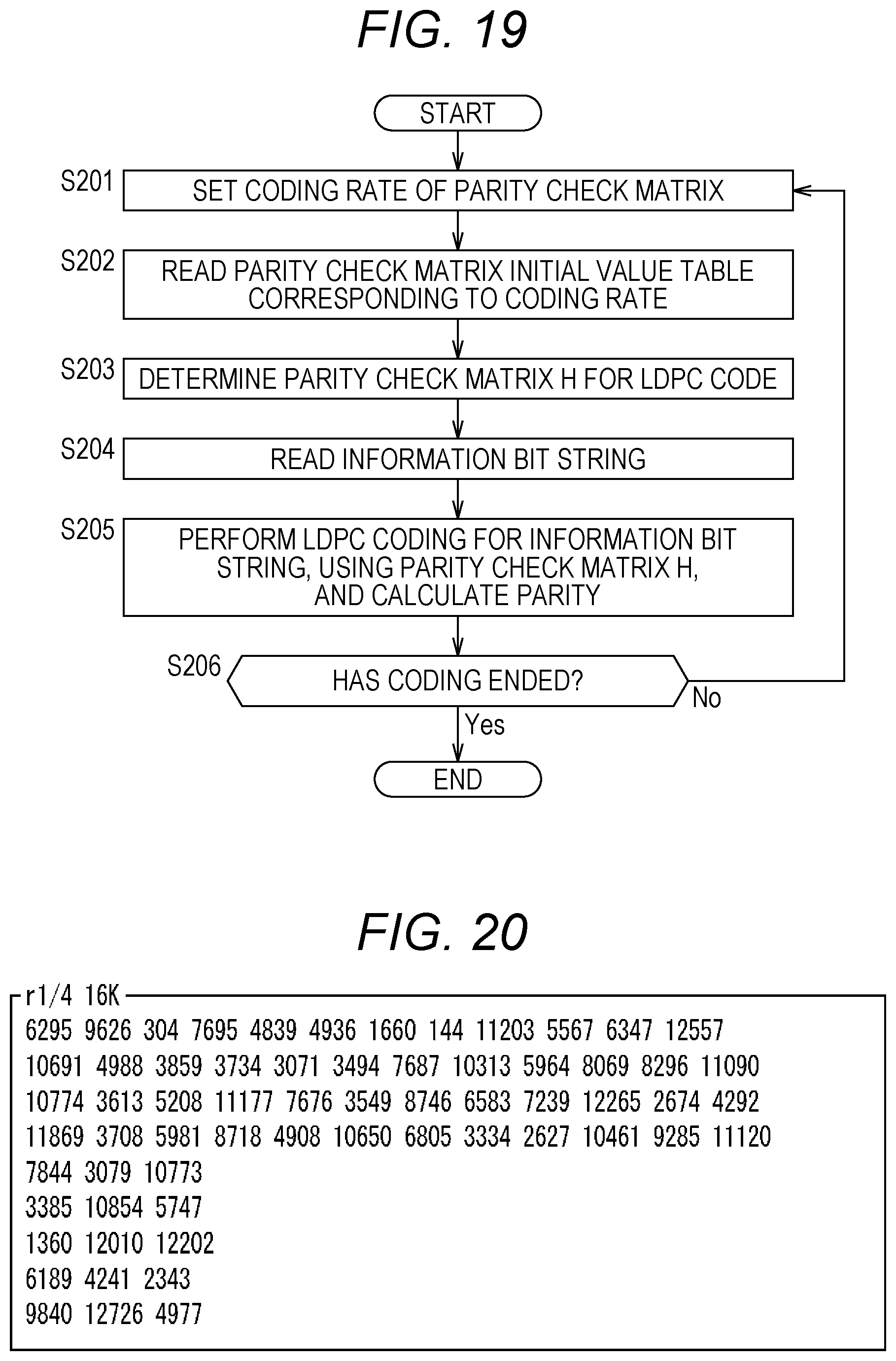
D00016

D00017

D00018

D00019

D00020

D00021

D00022

D00023

D00024

D00025
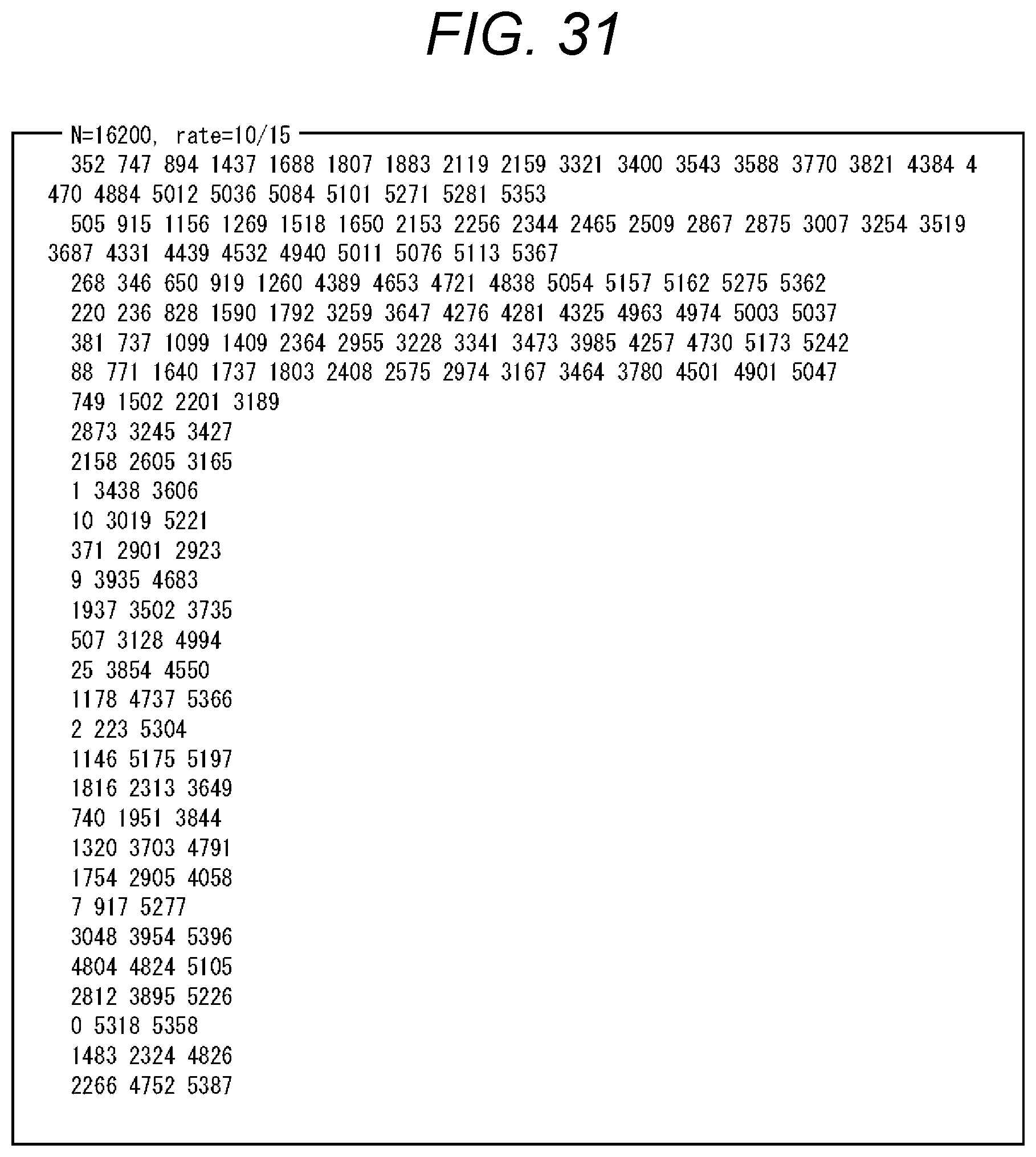
D00026

D00027

D00028

D00029

D00030

D00031

D00032

D00033

D00034

D00035

D00036

D00037

D00038

D00039

D00040

D00041

D00042

D00043

D00044
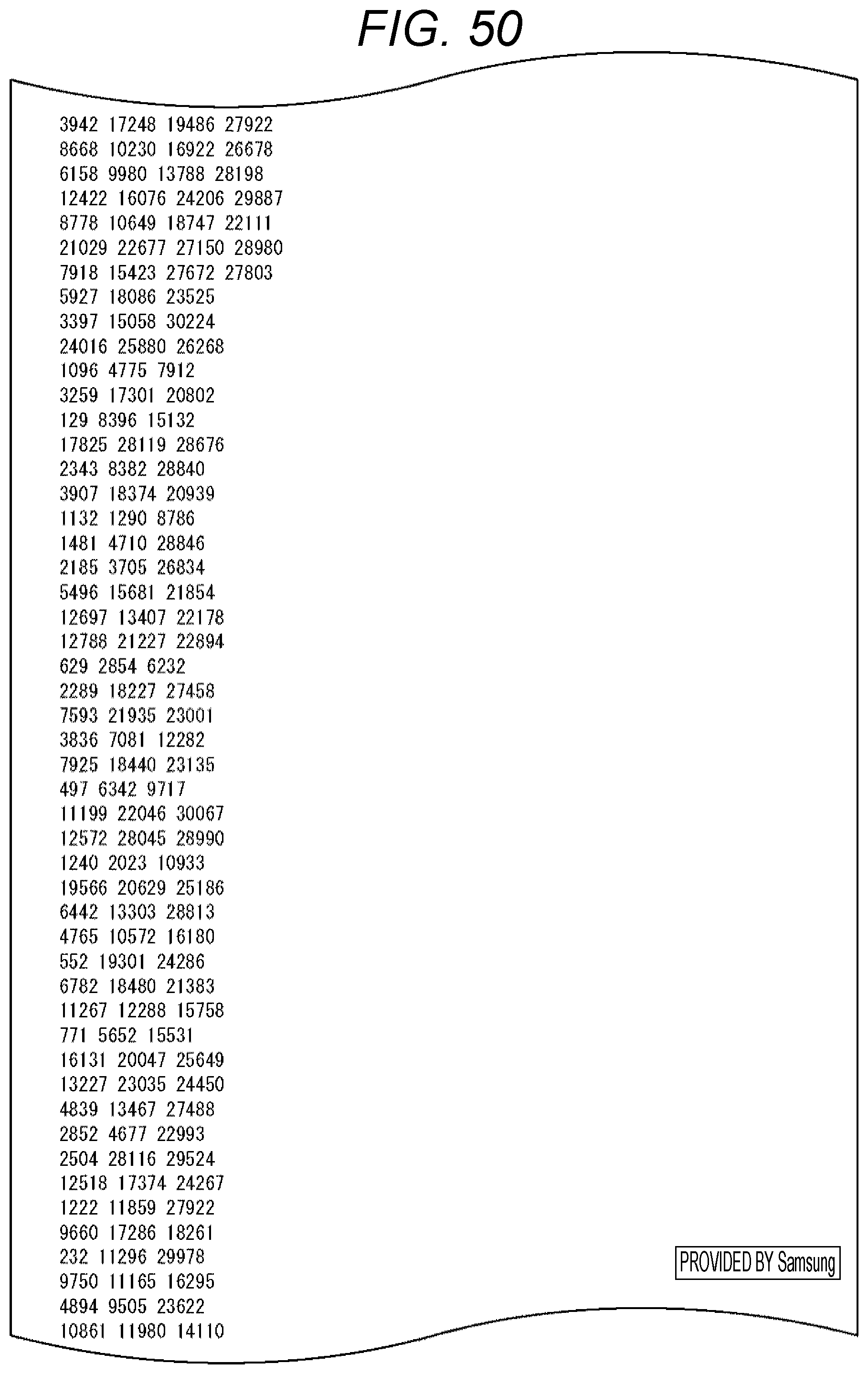
D00045

D00046

D00047

D00048

D00049

D00050

D00051

D00052

D00053

D00054

D00055

D00056

D00057

D00058

D00059

D00060

D00061

D00062

D00063

D00064

D00065

D00066

D00067

D00068

D00069

D00070

D00071

D00072

D00073

D00074

D00075

D00076

D00077

D00078

D00079

D00080

D00081

D00082

D00083

D00084

D00085

D00086

D00087

D00088

D00089

D00090

D00091

D00092

D00093

D00094

D00095

D00096

D00097

D00098

D00099

D00100

D00101

D00102

D00103

D00104

D00105

D00106

D00107

D00108

D00109

D00110

D00111

D00112

D00113

D00114

D00115

D00116

D00117

D00118

D00119

D00120

D00121

D00122

D00123

D00124

D00125
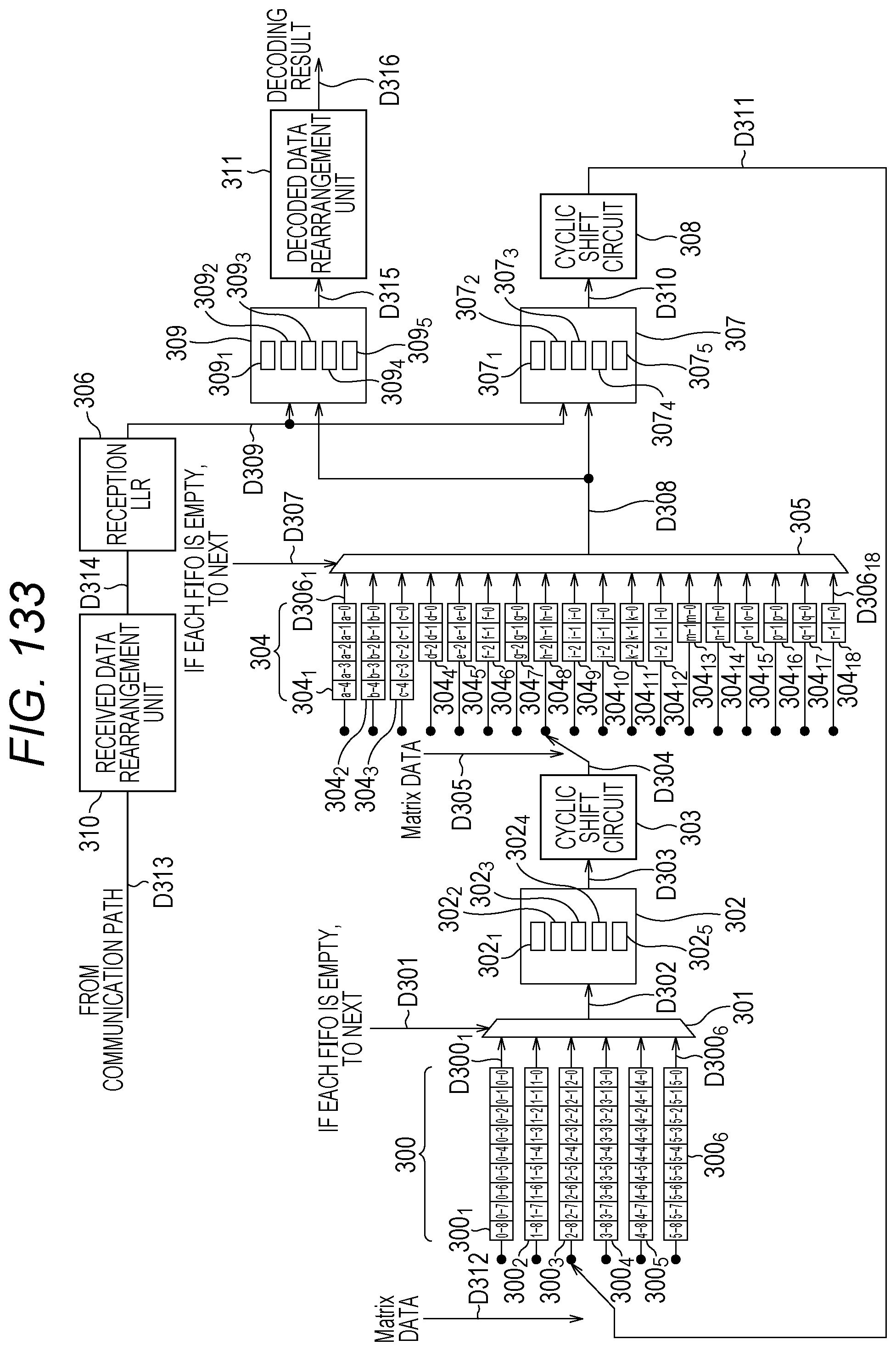
D00126

D00127

D00128

D00129

D00130

D00131
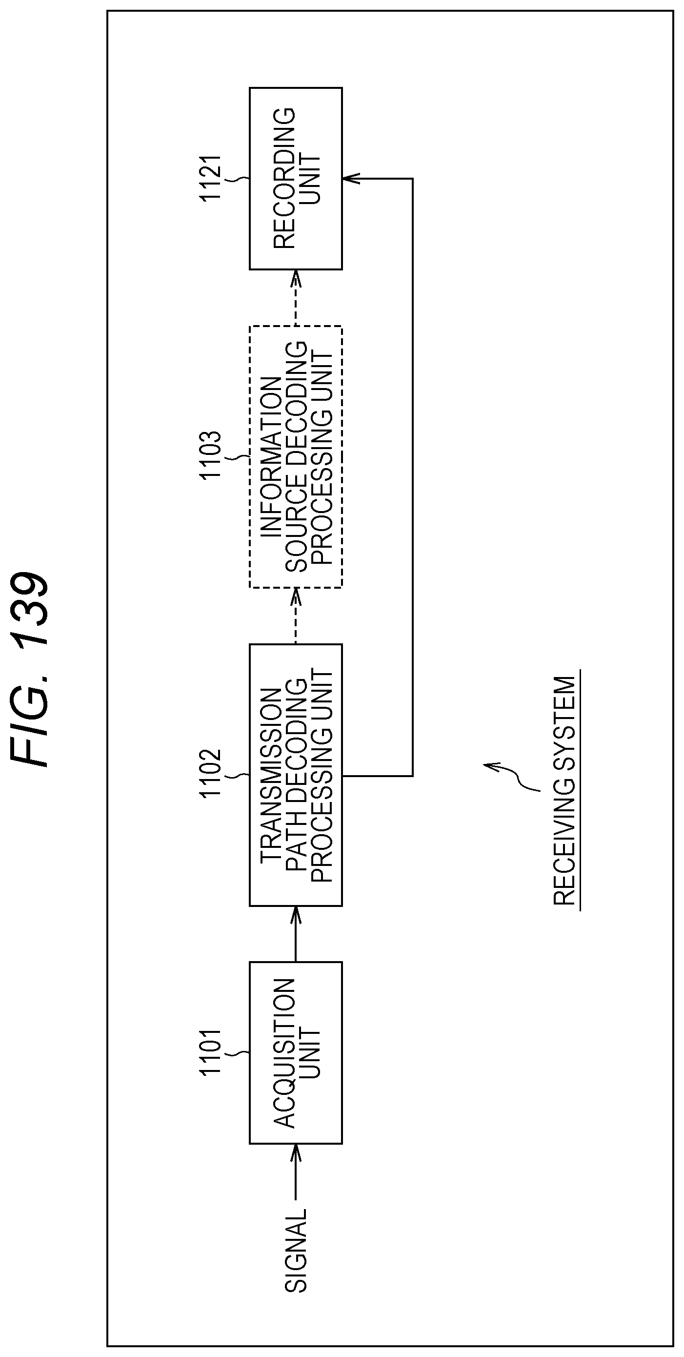
D00132
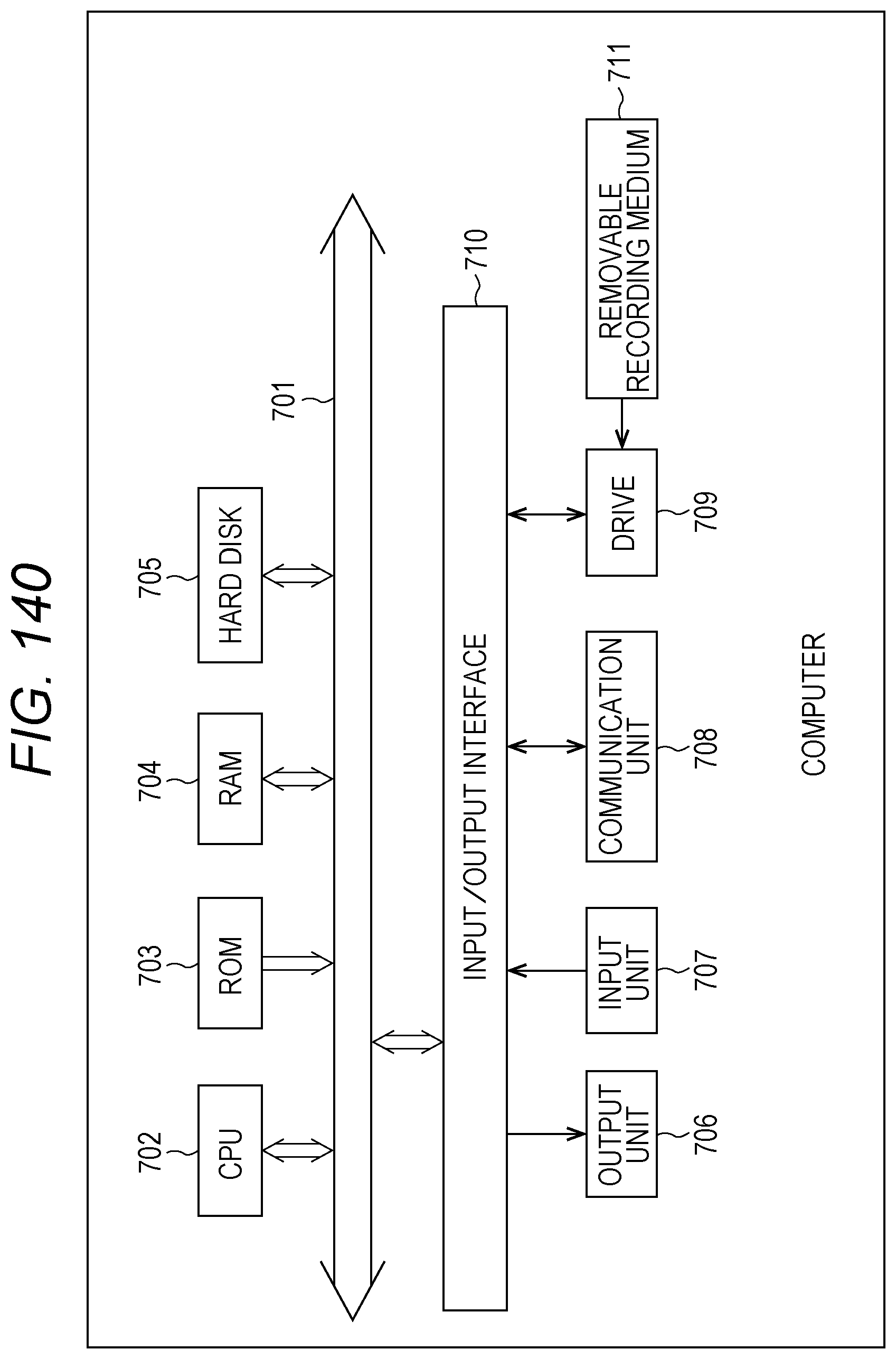
M00001

M00002

M00003

M00004

XML
uspto.report is an independent third-party trademark research tool that is not affiliated, endorsed, or sponsored by the United States Patent and Trademark Office (USPTO) or any other governmental organization. The information provided by uspto.report is based on publicly available data at the time of writing and is intended for informational purposes only.
While we strive to provide accurate and up-to-date information, we do not guarantee the accuracy, completeness, reliability, or suitability of the information displayed on this site. The use of this site is at your own risk. Any reliance you place on such information is therefore strictly at your own risk.
All official trademark data, including owner information, should be verified by visiting the official USPTO website at www.uspto.gov. This site is not intended to replace professional legal advice and should not be used as a substitute for consulting with a legal professional who is knowledgeable about trademark law.