Lithium battery cathode and method of manufacturing
Pan , et al. April 20, 2
U.S. patent number 10,985,373 [Application Number 15/442,803] was granted by the patent office on 2021-04-20 for lithium battery cathode and method of manufacturing. This patent grant is currently assigned to Global Graphene Group, Inc.. The grantee listed for this patent is Global Graphene Group, Inc.. Invention is credited to Hui He, Bor Z. Jang, Baofei Pan, Aruna Zhamu.


View All Diagrams
| United States Patent | 10,985,373 |
| Pan , et al. | April 20, 2021 |
Lithium battery cathode and method of manufacturing
Abstract
Provided is cathode active material layer for a lithium battery. The cathode active material layer comprises multiple cathode active material particles and an optional conductive additive that are bonded together by a binder comprising a high-elasticity polymer having a recoverable tensile strain from 5% to 700% (preferably from 10% to 100%) when measured without an additive or reinforcement in said polymer and a lithium ion conductivity no less than 10.sup.-5 S/cm (preferably and typically from 1.0.times.10.sup.-5 S/cm to 5.times.10.sup.-2 S/cm) at room temperature.
| Inventors: | Pan; Baofei (Dayton, OH), He; Hui (Dayton, OH), Zhamu; Aruna (Springboro, OH), Jang; Bor Z. (Centerville, OH) | ||||||||||
|---|---|---|---|---|---|---|---|---|---|---|---|
| Applicant: |
|
||||||||||
| Assignee: | Global Graphene Group, Inc.
(Dayton, OH) |
||||||||||
| Family ID: | 1000005501998 | ||||||||||
| Appl. No.: | 15/442,803 | ||||||||||
| Filed: | February 27, 2017 |
Prior Publication Data
| Document Identifier | Publication Date | |
|---|---|---|
| US 20180248189 A1 | Aug 30, 2018 | |
| Current U.S. Class: | 1/1 |
| Current CPC Class: | H01M 4/366 (20130101); H01M 4/62 (20130101); H01M 4/622 (20130101); H01M 4/625 (20130101); H01M 4/5825 (20130101); H01M 10/0525 (20130101); H01M 4/58 (20130101); H01M 4/5815 (20130101); H01M 2300/0068 (20130101); H01M 2300/0091 (20130101); H01M 4/38 (20130101); H01M 2004/028 (20130101); Y02E 60/10 (20130101); H01M 2300/0082 (20130101); H01M 12/08 (20130101); Y02T 10/70 (20130101) |
| Current International Class: | H01M 4/62 (20060101); H01M 4/36 (20060101); H01M 10/0525 (20100101); H01M 4/58 (20100101); H01M 4/38 (20060101); H01M 12/08 (20060101); H01M 4/02 (20060101) |
References Cited [Referenced By]
U.S. Patent Documents
| 2798878 | July 1957 | Hummers |
| 3836511 | September 1974 | O'farrell et al. |
| 4720910 | January 1988 | Rourke et al. |
| 5057339 | October 1991 | Ogawa |
| 5270417 | December 1993 | Soga et al. |
| 5342710 | August 1994 | Koksbang |
| 5350647 | September 1994 | Hope et al. |
| 5409785 | April 1995 | Nakano et al. |
| 5424151 | June 1995 | Koksbang et al. |
| 5434021 | July 1995 | Fauteux et al. |
| 5460905 | October 1995 | Skotheim |
| 5536599 | July 1996 | Alamgir et al. |
| 5648187 | July 1997 | Skotheim |
| 5961672 | October 1999 | Skotheim et al. |
| 6025094 | February 2000 | Visco et al. |
| 6218055 | April 2001 | Shah et al. |
| 6447952 | September 2002 | Spiegel et al. |
| 6451484 | September 2002 | Han et al. |
| 6475678 | November 2002 | Suzuki |
| 6515101 | February 2003 | Sheares |
| 6620547 | September 2003 | Sung et al. |
| 6733924 | May 2004 | Skotheim et al. |
| 6797428 | September 2004 | Skotheim et al. |
| 6936381 | August 2005 | Skotheim et al. |
| 7247408 | July 2007 | Skotheim et al. |
| 7282295 | October 2007 | Visco et al. |
| 7282296 | October 2007 | Visco et al. |
| 7282302 | October 2007 | Visco et al. |
| 7618678 | November 2009 | Mao et al. |
| 8597828 | December 2013 | Martinet et al. |
| 9905856 | February 2018 | Zhamu et al. |
| 10084182 | September 2018 | Pan et al. |
| 10483533 | November 2019 | Zhamu et al. |
| 10629899 | April 2020 | Jang |
| 2002/0034685 | March 2002 | Sato et al. |
| 2002/0182488 | December 2002 | Cho et al. |
| 2002/0195591 | December 2002 | Ravet et al. |
| 2003/0180619 | September 2003 | Tamura et al. |
| 2004/0018430 | January 2004 | Holman et al. |
| 2005/0034993 | February 2005 | Gozdz et al. |
| 2005/0098914 | May 2005 | Varma et al. |
| 2005/0118508 | June 2005 | Yong |
| 2005/0136330 | June 2005 | Mao et al. |
| 2006/0263697 | November 2006 | Dahn et al. |
| 2007/0218369 | September 2007 | Kaiduka et al. |
| 2007/0289879 | December 2007 | Horton |
| 2008/0248393 | October 2008 | Richard et al. |
| 2008/0318128 | December 2008 | Simoneau et al. |
| 2009/0155676 | June 2009 | Zhamu et al. |
| 2009/0169725 | July 2009 | Zhamu et al. |
| 2009/0186093 | July 2009 | Liu et al. |
| 2010/0099029 | April 2010 | Kinoshita et al. |
| 2010/0112454 | May 2010 | Visco et al. |
| 2010/0143798 | June 2010 | Zhamu et al. |
| 2010/0173198 | July 2010 | Zhamu et al. |
| 2011/0059361 | March 2011 | Wilkening et al. |
| 2011/0104571 | May 2011 | Zhamu et al. |
| 2011/0143211 | June 2011 | Takeyama |
| 2011/0177388 | July 2011 | Bae et al. |
| 2011/0244337 | October 2011 | Ohta et al. |
| 2011/0262816 | October 2011 | Amatucci |
| 2012/0064409 | March 2012 | Zhamu et al. |
| 2012/0070708 | March 2012 | Ohira et al. |
| 2012/0070746 | March 2012 | Mikhaylik et al. |
| 2012/0088154 | April 2012 | Liu et al. |
| 2013/0052544 | February 2013 | Ohkubo et al. |
| 2013/0054061 | February 2013 | Nishimoto |
| 2013/0157141 | June 2013 | Zhong et al. |
| 2013/0164615 | June 2013 | Manthiram et al. |
| 2013/0171339 | July 2013 | Wang et al. |
| 2013/0224603 | August 2013 | Chen et al. |
| 2013/0292613 | November 2013 | Wegner et al. |
| 2014/0072879 | March 2014 | Chen et al. |
| 2014/0147738 | May 2014 | Chen et al. |
| 2014/0147751 | May 2014 | Yang et al. |
| 2014/0154572 | June 2014 | Singh |
| 2014/0162121 | June 2014 | Ryu et al. |
| 2014/0178747 | June 2014 | Tsai et al. |
| 2014/0234702 | August 2014 | Zhang et al. |
| 2014/0235513 | August 2014 | Kverel et al. |
| 2014/0363746 | December 2014 | He et al. |
| 2015/0044556 | February 2015 | Wang et al. |
| 2015/0064568 | March 2015 | Yushin et al. |
| 2015/0064574 | March 2015 | He et al. |
| 2015/0079485 | March 2015 | Choi et al. |
| 2015/0162641 | June 2015 | Visco et al. |
| 2015/0180000 | June 2015 | Roumi |
| 2015/0180037 | June 2015 | Gronwald et al. |
| 2015/0218323 | August 2015 | Kim et al. |
| 2015/0221935 | August 2015 | Zhou et al. |
| 2015/0236372 | August 2015 | Yushin et al. |
| 2015/0244025 | August 2015 | Rhee et al. |
| 2015/0318532 | November 2015 | Manthiram et al. |
| 2015/0325844 | November 2015 | Inoue |
| 2015/0372294 | December 2015 | Minami et al. |
| 2016/0013481 | January 2016 | Jeong et al. |
| 2016/0043384 | February 2016 | Zhamu et al. |
| 2016/0087266 | March 2016 | Muldoon et al. |
| 2016/0126543 | May 2016 | Ota et al. |
| 2016/0149216 | May 2016 | Mizuno et al. |
| 2016/0181611 | June 2016 | Cho et al. |
| 2016/0204431 | July 2016 | Sawa |
| 2016/0218341 | July 2016 | Kumar et al. |
| 2016/0240896 | August 2016 | Zhang et al. |
| 2016/0301075 | October 2016 | Zhamu et al. |
| 2016/0344035 | November 2016 | Zhamu et al. |
| 2016/0351877 | December 2016 | Kusachi et al. |
| 2016/0351909 | December 2016 | Bittner et al. |
| 2016/0372743 | December 2016 | Cho et al. |
| 2016/0372784 | December 2016 | Hayner et al. |
| 2017/0002154 | January 2017 | Hiasa et al. |
| 2017/0018799 | January 2017 | Jeong |
| 2017/0033357 | February 2017 | Cho et al. |
| 2017/0047584 | February 2017 | Hwang et al. |
| 2017/0062827 | March 2017 | Bruckmeier et al. |
| 2017/0062830 | March 2017 | Bao et al. |
| 2017/0092986 | March 2017 | Ogawa et al. |
| 2017/0098824 | April 2017 | Fasching et al. |
| 2017/0098856 | April 2017 | Zhamu |
| 2017/0104204 | April 2017 | Zhamu et al. |
| 2017/0104217 | April 2017 | Yu et al. |
| 2017/0117535 | April 2017 | Yoon et al. |
| 2017/0117538 | April 2017 | Bendimerad et al. |
| 2017/0117589 | April 2017 | Tajima |
| 2017/0141387 | May 2017 | Hayner |
| 2017/0141399 | May 2017 | Lux |
| 2017/0166722 | June 2017 | Zhamu et al. |
| 2017/0179468 | June 2017 | Fanous |
| 2017/0194640 | July 2017 | Bucur et al. |
| 2017/0194648 | July 2017 | Bucur et al. |
| 2017/0200943 | July 2017 | Kawakami |
| 2017/0207484 | July 2017 | Zhamu et al. |
| 2017/0279125 | September 2017 | Ohsawa et al. |
| 2017/0288211 | October 2017 | Zhamu et al. |
| 2017/0294643 | October 2017 | Burshtain et al. |
| 2017/0309917 | October 2017 | Lee et al. |
| 2017/0338472 | November 2017 | Zhamu et al. |
| 2017/0338474 | November 2017 | Lee et al. |
| 2017/0338490 | November 2017 | Xiao et al. |
| 2018/0053978 | February 2018 | Song et al. |
| 2018/0083265 | March 2018 | Singh et al. |
| 2018/0190975 | July 2018 | Ishii et al. |
| 2018/0219215 | August 2018 | Bucur et al. |
| 2018/0233736 | August 2018 | Zhamu et al. |
| 2018/0241031 | August 2018 | Pan et al. |
| 2018/0241032 | August 2018 | Pan et al. |
| 2018/0248173 | August 2018 | Pan et al. |
| 2018/0277913 | September 2018 | Pan et al. |
| 2018/0287142 | October 2018 | Zhamu et al. |
| 2018/0294475 | October 2018 | Zhamu et al. |
| 2018/0294476 | October 2018 | Zhamu et al. |
| 2018/0301707 | October 2018 | Pan et al. |
| 2019/0051905 | February 2019 | Zhamu et al. |
| 2019/0058185 | February 2019 | Lee et al. |
| 2019/0077669 | March 2019 | Zhamu et al. |
| 2019/0081325 | March 2019 | Takeda et al. |
| 2019/0088958 | March 2019 | Viner et al. |
| 2019/0260028 | August 2019 | Zhamu et al. |
| 2019/0319303 | October 2019 | Kushida et al. |
| 2019/0386332 | December 2019 | Zhamu et al. |
| 2019/0393466 | December 2019 | Lin et al. |
| 2019/0393495 | December 2019 | He et al. |
| 2019/0393510 | December 2019 | He et al. |
| 2019/0393543 | December 2019 | Zhamu et al. |
| 103258990 | Aug 2013 | CN | |||
| 105322132 | Feb 2016 | CN | |||
| 108899472 | Nov 2018 | CN | |||
| 2787563 | Oct 2014 | EP | |||
| 1275613 | Nov 1989 | JP | |||
| 2010160984 | Jul 2010 | JP | |||
| 2011524611 | Sep 2011 | JP | |||
| 2015084320 | Apr 2015 | JP | |||
| 2015176656 | Oct 2015 | JP | |||
| 1020030050475 | Jun 2003 | KR | |||
| 100670527 | Jan 2007 | KR | |||
| 1020100138607 | Dec 2010 | KR | |||
| 1020140101640 | Aug 2014 | KR | |||
| 20160052351 | May 2016 | KR | |||
| 1020160085386 | Jul 2016 | KR | |||
| 1020160087511 | Jul 2016 | KR | |||
| 1020170001069 | Mar 2017 | KR | |||
| 1020170086003 | Jul 2017 | KR | |||
| 1020170126404 | Nov 2017 | KR | |||
| 1020180035752 | Apr 2018 | KR | |||
| 2007108424 | Sep 2007 | WO | |||
| 2015141799 | Sep 2015 | WO | |||
| WO-2016015915 | Feb 2016 | WO | |||
| 2017172104 | Oct 2017 | WO | |||
| 2017200798 | Nov 2017 | WO | |||
| 2018075538 | Apr 2018 | WO | |||
| 2018148090 | Aug 2018 | WO | |||
Other References
|
"Nylon", en.wikipedia.org/wiki/Nylon. Accessed Feb. 18, 2020. (Year: 2020). cited by examiner . An et al., "Diameter-Selected Synthesis of Single Crystalline Trigonal Selenium Nanowires" Materials Chemistry and Physics (2007) vol. 101, No. 2-3, pp. 357-361. cited by applicant . An et al., "Large-Scale Synthesis of High Quality Trigonal Selenium Nanowires" European Journal of Inorganic Chemistry (2003) vol. 17, pp. 3250-3255. cited by applicant . Arai et al., "Versatile supramolecular cross-linker: a rotaxane cross-linker that directly endows vinyl polymers with movable cross-links" Chemistry (2013) vol. 19, pp. 5917-5923. cited by applicant . Buonerba et al., "Novel Synthetic Strategy for the Sulfonation of Polybutadiene and Styrene-Butadiene Copolymers" Macromolecules (2013) vol. 46, pp. 778-784. cited by applicant . Chen et al., "Selenium nanowires and nanotubes synthesized via a facile template-free solution method" Materials Research Bulletin (2010) vol. 45, pp. 699-704. cited by applicant . Dwivedi et al., "An Organic Acid-induced Synthesis and Characterization of Selenium Nanoparticles" Journal of Nanotechnology (2011) Article ID 651971, 6 pages. cited by applicant . Elabd et al., "Sulfonation and Characterization of Poly(styrene-isobutylene-styrene) Triblock Copolymers at High Ion-Exchange Capacities" Polymer (2004) vol. 45, pp. 3037-3043. cited by applicant . Fan et al., "Hollow selenium encapsulated into 3D graphene hydrogels for lithium-selenium batteries with high rate performance and cycling stability" RSC Adv. (2017) vol. 7, pp. 21281-21286. cited by applicant . Gao et al., "Hollow Sphere Selenium Nanoparticles: Their In-Vitro Anti Hydroxyl Radical Effect" Advanced Materials (2002), vol. 14, No. 4, pp. 290-293. cited by applicant . Ji et al., "A highly ordered nanostructured carbon--sulphur cathode for lithium--sulphur batteries" Nature Materials (2009) vol. 8, pp. 500-506. cited by applicant . Karlicky et al., "Halogenated Graphenes: Rapidly Growing Family of Graphene Derivatives" ACS Nano (2013) vol. 7, No. 8, pp. 6434-6464. cited by applicant . Li et al., "Mixed Surfactant Template Method for Preparation of Nanometer Selenium" E-Journal of Chemistry (2009) vol. 6, No. S1, pp. S304-S310. cited by applicant . Lin et al., "Observation in the Growth of Selenium Nanoparticles" Journal of Chinese Chemical Society (2004) vol. 51, vol. 2, pp. 239-242. cited by applicant . Luesakul et al., "Shape-controlled synthesis of cubic-like selenium nanoparticles via the self-assembly method" Carbohydrate Polymers (2016) vol. 153, pp. 435-444. cited by applicant . PCT/US17/18452 International Search Report and Written Opinion dated Apr. 25, 2017, 9 pages. cited by applicant . PCT/US18/16404 International Search Report and Written Opinion dated Apr. 13, 2018, 11 pages. cited by applicant . PCT/US18/16410 International Search Report and Written Opinion dated Apr. 20, 2018, 10 pages. cited by applicant . PCT/US18/16418 International Search Report and Written Opinion dated Apr. 25, 2018, 9 pages. cited by applicant . PCT/US18/16423 International Search Report and Written Opinion dated Apr. 24, 2018, 9 pages. cited by applicant . PCT/US18/16431 International Search Report and Written Opinion dated Apr. 26, 2018, 6 pages. cited by applicant . PCT/US18/20892 International Search Report and Written Opinion dated May 2, 2018, 6 pages. cited by applicant . Xie et al., "A Novel Method for Synthesis of Sulfonated SBS Ionomers by Ring-Opening Reaction of Epoxidized SBS, Their Characterization, Properties, and Blends" Journal of Elastomers and Plastics (2007) vol. 39, pp. 317-334. cited by applicant . Zeng et al., "Solvothermal synthesis of trigonal selenium with butterfly-like microstructure" Particuology (2013) vol. 11, No. 5, pp. 614-617. cited by applicant . Zhang et al., "Synthesis of selenium nanoparticles in the presence of polysaccharides" Materials Letters (2004) vol. 38, No. 21, pp. 2590-2594. cited by applicant . PCT/US18/16426 International Search Report and Written Opinion dated Apr. 24, 2018, 9 pages. cited by applicant . Choi et al., "Highly elastic binders integrating polyrotaxanes for silicon microparticle anodes in lithium ion batteries" Science (2017) vol. 357, No. 6348, pp. 279-283. cited by applicant . KR-10-2015-0044333 English language translation. cited by applicant . PCT/US18/25160 International Search Report and Written Opinion dated Nov. 21, 2018, 12 pages. cited by applicant . PCT/US18/43421 International Search Report and Written Report dated Oct. 11, 2018, 13 pages. cited by applicant . PCT/US18/43435 International Search Report and Written Opinion dated Jan. 7, 2019, 14 pages. cited by applicant . U.S. Appl. No. 14/999,080 Nonfinal Office Action dated Nov. 9, 2018. cited by applicant . U.S. Appl. No. 15/442,807 Nonfinal Office Action dated Dec. 14, 2018, 7 pages. cited by applicant . U.S. Appl. No. 15/483,342 Final Office Action dated Mar. 22, 2019, 52 pages. cited by applicant . U.S. Appl. No. 15/483,342 Nonfinal Office Action dated Nov. 2, 2018, 37 pages. cited by applicant . U.S. Appl. No. 15/483,347 Final Office Action dated Apr. 16, 2019, 23 pages. cited by applicant . U.S. Appl. No. 15/483,347 Nonfinal Office Action dated Nov. 2, 2018, 20 pages. cited by applicant . U.S. Appl. No. 15/483,348 Final Office Action dated Apr. 9, 2019, 28 pages. cited by applicant . U.S. Appl. No. 15/483,348 Nonfinal Office Action dated Nov. 21, 2018, 22 pages. cited by applicant . Wikipedia contributors. "Anode." Wikipedia, The Free Encyclopedia, Mar. 4, 2019, Web. Mar. 18, 2019. (Year: 2019). cited by applicant . Wikipedia contributors. "Molar mass distribution." Wikipedia, The Free Encyclopedia, Feb. 1, 2019, Web. Mar. 18, 2019. (Year: 2019). cited by applicant . Habib et al., "Elastomeric Nanocomposite Based on Exfoliated Graphene Oxide and Its Characteristics without Vulcanization" Hindawi Journal of Nanomaterials (2017) vol. 2017, Article ID 8543137, 11 pages. cited by applicant . Liu et al., "Solutions for the problems of silicon-carbon anode materials for lithium-ion batteries" Royal Society Open Science (2018) vol. 5, p. 172370. cited by applicant . PCT/US18/25135 International Search Report and Written Opinion dated Jun. 27, 2018, 14 pages. cited by applicant . PCT/US18/25150 International Search Report and Written Opinion dated Jun. 29, 2018, 14 pages. cited by applicant . PCT/US18/25163 International Search Report and Written Opinion dated Jul. 27, 2018, 19 pages. cited by applicant . PCT/US19/18931 International Search Report and Written Opinion dated May 8, 2019, 13 pages. cited by applicant . PCT/US19/19061 International Search Report and Written Opinion dated May 13, 2019, 11 pages. cited by applicant . PCT/US19/19062 International Search Report and Written Opinion dated May 13, 2019, 9 pages. cited by applicant . PCT/US19/20214 International Search Report and Written Opinion dated May 2, 2019, 7 pages. cited by applicant . PCT/US19/20222 International Search Report and Written Opinion dated May 3, 2019, 7 pages. cited by applicant . Vaikhanski et al., "Fiber-reinforced composite foam from expandable PVC microspheres" Composites Part A (2003) vol. 34, pp. 1245-1253. cited by applicant . PCT/US19/21137 International Search Report and Written Opinion dated Jun. 18, 2019, 13 pages. cited by applicant . U.S. Appl. No. 15/901,367 Nonfinal Office Action dated Jun. 10, 2019, 12 pages. cited by applicant . U.S. Appl. No. 15/478,125 Final Office Action dated Sep. 3, 2020, 19 pages. cited by applicant . U.S. Appl. No. 15/914,213 Nonfinal Office Action dated Aug. 31, 2020, 8 pages. cited by applicant . U.S. Appl. No. 15/954,088 Final Office Action dated Aug. 7, 2020, 8 pages. cited by applicant . U.S. Appl. No. 16/010,213 Final Office Action dated Jun. 15, 2018, 10 pages. cited by applicant . U.S. Appl. No. 16/109,142 Nonfinal Office Action dated Oct. 13, 2020, 9 pages. cited by applicant . U.S. Appl. No. 16/112,225 Final Office Action dated Oct. 1, 2020, 12 pages. cited by applicant . U.S. Appl. No. 16/160,257 Final Office Action dated Oct. 14, 2020, 15 pages. cited by applicant . U.S. Appl. No. 16/238,052 Final Office Action dated Oct. 14, 2020, 15 pages. cited by applicant . U.S. Appl. No. 16/238,061 Nonfinal Office Action dated Aug. 14, 2020, 8 pages. cited by applicant . U.S. Appl. No. 16/112,225 Nonfinal Office Action dated May 13, 2020, 9 pages. cited by applicant . U.S. Appl. No. 16/113,676 Nonfinal Office Action dated Oct. 4, 2019, 9 pages. cited by applicant . U.S. Appl. No. 16/113/676 Final Office Action dated Apr. 9, 2020, 15 pages. cited by applicant . U.S. Appl. No. 16/114,959 Final Office Action dated Jul. 22, 2020, 6 pages. cited by applicant . U.S. Appl. No. 16/116,329 Final Office Action dated Jul. 23, 2020, 6 pages. cited by applicant . U.S. Appl. No. 16/116,329 Nonfinal Office Action dated Mar. 30, 2020, 6 pages. cited by applicant . U.S. Appl. No. 16/116,341 Final Office Action dated Jul. 23, 2020, 6 pages. cited by applicant . U.S. Appl. No. 16/116,341 Nonfinal Office Action dated Mar. 30, 2020, 6 pages. cited by applicant . U.S. Appl. No. 16/120,875 Final Office Action dated Apr. 9, 2020, 14 pages. cited by applicant . U.S. Appl. No. 16/120,875 Nonfinal Office Action dated Oct. 4, 2019, 10 pages. cited by applicant . U.S. Appl. No. 16/123,218 Final Office Action dated Apr. 9, 2020, 13 pages. cited by applicant . U.S. Appl. No. 16/123,218 Nonfinal Office Action dated Oct. 4, 2019, 9 pages. cited by applicant . U.S. Appl. No. 16/126,736 Final Office Action dated Jul. 23, 2020, 6 pages. cited by applicant . U.S. Appl. No. 16/126,736 Nonfinal Office Action dated Mar. 30, 2020, 6 pages. cited by applicant . U.S. Appl. No. 16/126,745 Final Office Action dated Jul. 23, 2020, 6 pages. cited by applicant . U.S. Appl. No. 16/126,745 Nonfinal Office Action dated Mar. 30, 2020, 6 pages. cited by applicant . U.S. Appl. No. 16/160,257 Nonfinal Office Action dated Apr. 3, 2020, 16 pages. cited by applicant . U.S. Appl. No. 16/166,536 Nonfinal Office Action dated May 14, 2020, 5 pages. cited by applicant . U.S. Appl. No. 16/166,574 Final Office Action dated Apr. 9, 2020, 12 pages. cited by applicant . U.S. Appl. No. 16/166,574 Nonfinal Office Action dated Oct. 4, 2019, 9 pages. cited by applicant . U.S. Appl. No. 16/238,052 Nonfinal Office Action dated Apr. 3, 2020, 14 pages. cited by applicant . U.S. Appl. No. 16/256,321 Nonfinal Office Action dated Jul. 27, 2020, 8 pages. cited by applicant . U.S. Appl. No. 16/256,346 Nonfinal Office Action dated May 19, 2020, 16 pages. cited by applicant . AZO Materials Table of Properties on Styrene Butadiene Rubber, 5 pages. cited by applicant . PCT/US19/27147 International Search Report and Written Opinion dated Aug. 1, 2019, 16 pages. cited by applicant . PCT/US19/36748 International Search Report and Written Opinion dated Oct. 16, 2019, 11 pages. cited by applicant . PCT/US19/37690 International Search Report and Written Opinion dated Oct. 18, 2019, 18 pages. cited by applicant . PCT/US19/37692 International Search Report and Written Opinion dated Oct. 21, 2019, 18 pages. cited by applicant . PCT/US19/37700 International Search Report and Written Opinion dated Oct. 23, 2019, 17 pages. cited by applicant . PCT/US19/38367 International Search Report and Written Opinion dated Oct. 18, 2019, 17 pages. cited by applicant . PCT/US19/38368 International Search Report and Written Opinion dated Oct. 18, 2019, 18 pages. cited by applicant . PCT/US19/38436 International Search Report and Written Opinion dated Oct. 16, 2019, 17 pages. cited by applicant . PCT/US19/38455 International Search Report and Written Opinion dated Oct. 18, 2019, 10 pages. cited by applicant . PCT/US19/38456 International Search Report and Written Opinion dated Oct. 16, 2019, 16 pages. cited by applicant . PCT/US19/38881 International Search Report and Written Opinion dated Oct. 18, 2019, 14 pages. cited by applicant . PCT/US19/47642 International Search Report and Written Opinion dated Dec. 6, 2019, 16 pages. cited by applicant . PCT/US19/48084 International Search Report and Written Opinion dated Dec. 16, 2019, 9 pages. cited by applicant . PCT/US19/55758 International Search Report and Written Opinion dated Jan. 31, 2020, 15 pages. cited by applicant . PCT/US20/14869 International Search Report and Written Opinion dated May 19, 2020, 13 pages. cited by applicant . U.S. Appl. No. 14/999,080 Nonfinal Office Action dated Oct. 30, 2019, 15 pages. cited by applicant . U.S. Appl. No. 15/434,632 Final Office Action dated Dec. 26, 2019, 20 pages. cited by applicant . U.S. Appl. No. 15/434,632 Nonfinal Office Action dated Jun. 26, 2020, 19 pages. cited by applicant . U.S. Appl. No. 15/442,278 Final Office Action dated Oct. 21, 2019, 16 pages. cited by applicant . U.S. Appl. No. 15/442,278 Nonfinal Office Action dated Feb. 28, 2020, 16 pages. cited by applicant . U.S. Appl. No. 15/478,125 Final Office Action dated Aug. 23, 2019, 14 pages. cited by applicant . U.S. Appl. No. 15/478,125 Nonfinal Office Action dated Mar. 5, 2020, 11 pages. cited by applicant . U.S. Appl. No. 15/483,347 Final Office Action dated Dec. 27, 2019, 22 pages. cited by applicant . U.S. Appl. No. 15/483,347 Nonfinal Office Action dated Jun. 17, 2020, 14 pages. cited by applicant . U.S. Appl. No. 15/483,347 Nonfinal Office Action dated Sep. 17, 2019, 20 pages. cited by applicant . U.S. Appl. No. 15/483,348 Advisory Action dated Jul. 18, 2019, 9 pages. cited by applicant . U.S. Appl. No. 15/483,348 Final Office Action dated Jan. 20, 2020, 9 pages. cited by applicant . U.S. Appl. No. 15/483,348 Nonfinal Office Action dated Sep. 16, 2019, 22 pages. cited by applicant . U.S. Appl. No. 15/485,934 Nonfinal Office Action dated May 26, 2020, 12 pages. cited by applicant . U.S. Appl. No. 15/676,677 Nonfinal Office Action dated Feb. 5, 2020, 15 pages. cited by applicant . U.S. Appl. No. 15/676,680 Nonfinal Office Action dated May 20, 2020, 8 pages. cited by applicant . U.S. Appl. No. 15/903,788 Nonfinal Office Action dated Jun. 4, 2020, 11 pages. cited by applicant . U.S. Appl. No. 15/903,808 Final Office Action dated May 15, 2020, 9 pages. cited by applicant . U.S. Appl. No.15/903,808 Nonfinal Office Action dated Jan. 28, 2020, 8 pages. cited by applicant . U.S. Appl. No. 15/910,465 Final Office Action dated May 15, 2020, 13 pages. cited by applicant . U.S. Appl. No. 15/910,465 Nonfinal Office Action dated Nov. 1, 2019, 12 pages. cited by applicant . U.S. Appl. No. 15/910,471 Nonfinal Office Action dated May 13, 2020, 11 pages. cited by applicant . U.S. Appl. No. 15/910,471 Non-final Office Action dated Nov. 8, 2019, 12 pages. cited by applicant . U.S. Appl. No. 15/914,216 Final Office Action dated Dec. 19, 2019, 9 pages. cited by applicant . U.S. Appl. No. 15/954,088 Nonfinal Office Action dated Mar. 13, 2020, 9 pages. cited by applicant . U.S. Appl. No. 16/010,213 Nonfinal Office Action dated Mar. 27, 2020, 12 pages. cited by applicant . U.S. Appl. No. 16/010,225 Final Office Action dated Jul. 8, 2020, 7 pages. cited by applicant . U.S. Appl. No. 16/010,225 Nonfinal Office Action dated Mar. 27, 2020, 13 pages. cited by applicant . U.S. Appl. No. 16/010,965 Nonfinal Office Action dated Jan. 8, 2020, 5 pages. cited by applicant . U.S. Appl. No. 16/010,975 Nonfinal Office Action dated Jan. 8, 2020, 5 pages. cited by applicant . U.S. Appl. No. 16/014,623 Final Office Action dated Apr. 9, 2020, 14 pages. cited by applicant . U.S. Appl. No. 16/014,623 Nonfinal Office Action dated Oct. 4, 2019, 8 pages. cited by applicant . U.S. Appl. No. 16/017,294 Nonfinal Office Action dated Jan. 23, 2020, 6 pages. cited by applicant . U.S. Appl. No. 16/112,208 Nonfinal Office Action dated Apr. 2, 2020, 7 pages. cited by applicant. |
Primary Examiner: Jelsma; Jonathan G
Claims
We claim:
1. A cathode active material layer for a lithium battery, said cathode active material layer comprising multiple cathode active material particles and an optional conductive additive that are bonded together by a binder comprising a high-elasticity polymer having a recoverable tensile strain from 5% to 700% when measured without an additive or reinforcement in said polymer and a lithium ion conductivity no less than 10.sup.-5 S/cm at room temperature, wherein said high-elasticity polymer forms a mixture or interpenetrating network with an elastomer selected from natural polyisoprene, synthetic polyisoprene, polybutadiene, chloroprene rubber, polychloroprene, butyl rubber, styrene-butadiene rubber, nitrile rubber, ethylene propylene rubber, ethylene propylene diene rubber, epichlorohydrin rubber, polyacrylic rubber, silicone rubber, fluorosilicone rubber, perfluoroelastomers, polyether block amides, chlorosulfonated polyethylene, ethylene-vinyl acetate, protein resilin, protein elastin, ethylene oxide-epichlorohydrin copolymer, polyurethane, urethane-urea copolymer, or a combination thereof.
2. The cathode active material layer of claim 1, wherein said high-elasticity polymer contains a cross-linked network of polymer chains having an ether linkage, nitrile-derived linkage, benzo peroxide-derived linkage, ethylene oxide linkage, propylene oxide linkage, vinyl alcohol linkage, cyano-resin linkage, triacrylate monomer-derived linkage, tetraacrylate monomer-derived linkage, or a combination thereof in said cross-linked network of polymer chains.
3. The cathode active material layer of claim 1, wherein said high-elasticity polymer contains a cross-linked network of polymer chains selected from nitrile-containing polyvinyl alcohol chains, cyanoresin chains, pentaerythritol tetraacrylate chains, pentaerythritol triacrylate chains, ethoxylated trimethylolpropane triacrylate (ETPTA) chains, ethylene glycol methyl ether acrylate (EGMEA) chains, or a combination thereof.
4. The cathode active material layer of claim 1, wherein said cathode active material is selected from an inorganic material, an organic material, a polymeric material, or a combination thereof.
5. The cathode active material layer of claim 4, wherein said inorganic material is selected from a metal oxide, metal phosphate, metal silicide, metal selenide, transition metal sulfide, or a combination thereof.
6. The cathode active material layer of claim 5, wherein said metal oxide contains a vanadium oxide selected from the group consisting of VO.sub.2, Li.sub.xVO.sub.2, V.sub.2O.sub.5, Li.sub.xV.sub.2O.sub.5, V.sub.3O.sub.8, Li.sub.xV.sub.3O.sub.8, Li.sub.xV.sub.3O.sub.7, V.sub.4O.sub.9, Li.sub.xV.sub.4O.sub.9, V.sub.6O.sub.13, Li.sub.xV.sub.6O.sub.13, their doped versions, their derivatives, and combinations thereof, wherein 0.1<x<5.
7. The cathode active material layer of claim 5, wherein said metal oxide or metal phosphate is selected from a layered compound LiMO.sub.2, spinel compound LiM.sub.2O.sub.4, olivine compound LiMPO.sub.4, silicate compound Li.sub.2MSiO.sub.4, Tavorite compound LiMPO.sub.4F, borate compound LiMBO.sub.3, or a combination thereof, wherein M is a transition metal or a mixture of multiple transition metals.
8. The cathode active material layer of claim 5, wherein said inorganic material is selected from: (a) bismuth selenide or bismuth telluride, (b) transition metal dichalcogenide or trichalcogenide, (c) sulfide, selenide, or telluride of niobium, zirconium, molybdenum, hafnium, tantalum, tungsten, titanium, cobalt, manganese, iron, nickel, or a transition metal; (d) boron nitride, or (e) a combination thereof.
9. The cathode active material layer of claim 4, wherein said inorganic material is selected from a lithium cobalt oxide, lithium nickel oxide, lithium manganese oxide, lithium vanadium oxide, lithium-mixed metal oxide, lithium iron phosphate, lithium manganese phosphate, lithium vanadium phosphate, lithium mixed metal phosphate, lithium metal silicide, or a combination thereof.
10. The cathode active material layer of claim 4, wherein said inorganic material is selected from a metal fluoride or metal chloride including the group consisting of CoF.sub.3, MnF.sub.3, FeF.sub.3, VF.sub.3, VOF.sub.3, TiF.sub.3, BiF.sub.3, NiF.sub.2, FeF.sub.2, CuF.sub.2, CuF, SnF.sub.2, AgF, CuCl.sub.2, FeCl.sub.3, MnCl.sub.2, and combinations thereof.
11. The cathode active material layer of claim 4, wherein said inorganic material is selected from a lithium transition metal silicate, denoted as Li.sub.2MSiO.sub.4 or Li.sub.2Ma.sub.xMb.sub.ySiO.sub.4, wherein M and Ma are selected from Fe, Mn, Co, Ni, V, or VO; Mb is selected from Fe, Mn, Co, Ni, V, Ti, Al, B, Sn, or Bi; and x+y.ltoreq.1.
12. The cathode active material layer of claim 4, wherein said inorganic material is selected from a transition metal dichalcogenide, a transition metal trichalcogenide, or a combination thereof.
13. The cathode active material layer of claim 4, wherein said inorganic material is selected from TiS.sub.2, TaS.sub.2, MoS.sub.2, NbSe.sub.3, MnO.sub.2, CoO.sub.2, an iron oxide, a vanadium oxide, or a combination thereof.
14. The cathode active material layer of claim 4, wherein said organic material or polymeric material is selected from poly(anthraquinonyl sulfide) (PAQS), a lithium oxocarbon, 3,4,9,10-perylenetetracarboxylic dianhydride (PTCDA), poly(anthraquinonyl sulfide), pyrene-4,5,9,10-tetraone (PYT), polymer-bound PYT, quino(triazene), redox-active organic material, tetracyanoquinodimethane (TCNQ), tetracyanoethylene (TCNE), 2,3,6,7,10,11-hexamethoxytriphenylene (HMTP), poly(5-amino-1,4-dyhydroxy anthraquinone) (PADAQ), phosphazene disulfide polymer ([(NPS.sub.2).sub.3]n), lithiated 1,4,5,8naphthalenetetraol formaldehyde polymer, hexaazatrinaphtylene (HATN), hexaazatriphenylene hexacarbonitrile (HAT(CN).sub.6), 5-benzylidene hydantoin, isatine lithium salt, pyromellitic diimide lithium salt, tetrahydroxy-p-benzoquinone derivatives (THQLi.sub.4), N,N'-diphenyl-2,3,5,6-tetraketopiperazine (PHP), N,N'-diallyl-2,3,5,6-tetraketopiperazine (AP), N,N'-dipropyl-2,3,5,6-tetraketopiperazine (PRP), a thioether polymer, a quinone compound, 1,4-benzoquinone, 5,7,12,14-pentacenetetrone (PT), 5-amino-2,3-dihydro-1,4-dyhydroxy anthraquinone (ADDAQ), 5-amino-1,4-dyhydroxy anthraquinone (ADAM), calixquinone, Li.sub.4C.sub.6O.sub.6, Li.sub.2C.sub.6O.sub.6, Li.sub.6C.sub.6O.sub.6, or a combination thereof.
15. The cathode active material layer of claim 14, wherein said thioether polymer is selected from poly[methanetetryl-tetra(thiomethylene)] (PMTTM), poly(2,4-dithiopentanylene) (PDTP), a polymer containing poly(ethene-1,1,2,2-tetrathiol) (PETT) as a main-chain thioether polymers, a side-chain thioether polymer having a main-chain consisting of conjugating aromatic moieties, and having a thioether side chain as a pendant, poly(2-phenyl-1,3-dithiolane) (PPDT), poly(1,4-di(1,3-dithiolan-2-yl)benzene) (PDDTB), poly(tetrahydrobenzodithiophene) (PTHBDT), poly[1,2,4,5-tetrakis(propylthio)benzene] (PTKPTB), or poly[3,4(ethylenedithio)thiophene] (PEDTT).
16. The cathode active material layer of claim 4, wherein said organic material contains a phthalocyanine compound selected from copper phthalocyanine, zinc phthalocyanine, tin phthalocyanine, iron phthalocyanine, lead phthalocyanine, nickel phthalocyanine, vanadyl phthalocyanine, fluorochromium phthalocyanine, magnesium phthalocyanine, manganous phthalocyanine, dilithium phthalocyanine, aluminum phthalocyanine chloride, cadmium phthalocyanine, chlorogallium phthalocyanine, cobalt phthalocyanine, silver phthalocyanine, a metal-free phthalocyanine, a chemical derivative thereof, or a combination thereof.
17. The cathode active material layer of claim 1, wherein said cathode active material is in a form of nano particle, nano wire, nano fiber, nano tube, nano sheet, nano belt, nano ribbon, nano disc, nano platelet, or nano horn having a thickness or diameter from 0.5 nm to 100 nm.
18. The cathode active material layer of claim 17, wherein said nano particle, nano wire, nano fiber, nano tube, nano sheet, nano belt, nano ribbon, nano disc, nano platelet, or nano horn is coated with or embraced by a conductive protective coating selected from a carbon material, graphene, electronically conductive polymer, conductive metal oxide, or conductive metal coating.
19. The cathode active material layer of claim 1, wherein one or a plurality of said particles is coated with a layer of carbon or graphene.
20. The cathode active material layer of claim 1, wherein said conductive additive is selected from a graphite, graphene, or carbon, or a combination thereof.
21. The cathode active material layer of claim 20, wherein said graphite or carbon material is selected from polymeric carbon, amorphous carbon, chemical vapor deposition carbon, coal tar pitch, petroleum pitch, meso-phase pitch, carbon black, coke, acetylene black, activated carbon, fine expanded graphite particle with a dimension smaller than 100 nm, artificial graphite particle, natural graphite particle, or a combination thereof.
22. The cathode active material layer of claim 1, wherein said high-elasticity polymer has a lithium ion conductivity no less than 10.sup.-4 S/cm.
23. The cathode active material layer of claim 1, wherein said high-elasticity polymer has a lithium ion conductivity no less than 10.sup.-3 S/cm.
24. The cathode active material layer of claim 1, wherein said high-elasticity polymer is a neat polymer having no additive or filler dispersed therein.
25. The cathode active material layer of claim 1, wherein said high-elasticity polymer contains from 0.1% to 50% by weight of a lithium ion-conducting additive dispersed therein, or contains therein from 0.1% by weight to 10% by weight of a reinforcement nano filament selected from carbon nanotube, carbon nano-fiber, graphene, or a combination thereof, based on the total weight of said high-elasticity polymer.
26. The cathode active material layer of claim 1, wherein said high-elasticity polymer is mixed with a lithium ion-conducting additive to form a composite wherein said lithium ion-conducting additive is dispersed in said high-elasticity polymer and is selected from Li.sub.2CO.sub.3, Li.sub.2O, Li.sub.2C.sub.2O.sub.4, LiOH, LiX, ROCO.sub.2Li, HCOLi, ROLi, (ROCO.sub.2Li).sub.2, (CH.sub.2OCO.sub.2Li).sub.2, Li.sub.2S, Li.sub.xSO.sub.y, or a combination thereof, wherein X=F, Cl, I, or Br, R=a hydrocarbon group, 0<x.ltoreq.1 and 1.ltoreq.y.ltoreq.4.
27. The cathode active material layer of claim 1, wherein said high-elasticity polymer is mixed with a lithium ion-conducting additive to form a composite wherein said lithium ion-conducting additive is dispersed in said high-elasticity polymer and is selected from lithium perchlorate (LiClO.sub.4), lithium hexafluorophosphate (LiPF.sub.6), lithium borofluoride (LiBF.sub.4), lithium hexafluoroarsenide (LiAsF.sub.6), lithium trifluoro-methanesulfonate (LiCF.sub.3SO.sub.3), bis-trifluoromethyl sulfonylimide lithium (LiN(CF.sub.3SO.sub.2).sub.2), lithium bis(oxalato)borate (LiBOB), lithium oxalyldifluoroborate (LiBF.sub.2C.sub.2O.sub.4), lithium nitrate (LiNO.sub.3), Li-fluoroalkyl-phosphate (LiPF.sub.3(CF.sub.2CF.sub.3).sub.3), lithium bisperfluoro-ethylsulfonylimide (LiBETI), lithium bis(trifluoromethanesulfonyl)imide, lithium bis(fluorosulfonyl)imide, lithium trifluoromethanesulfonimide (LiTFSI), an ionic liquid-based lithium salt, and combinations thereof.
28. The cathode active material layer of claim 1, wherein said high-elasticity polymer is mixed with an electron-conducting polymer selected from polyaniline, polypyrrole, polythiophene, polyfuran, a bi-cyclic polymer, a sulfonated derivative thereof, or a combination thereof to form a blend, co-polymer, or semi-interpenetrating network.
29. The cathode active material layer of claim 1, wherein the high-elasticity polymer forms a mixture or blend with a lithium ion-conducting polymer selected from poly(ethylene oxide) (PEO), polypropylene oxide (PPO), poly(acrylonitrile) (PAN), poly(methyl methacrylate) (PMMA), poly(vinylidene fluoride) (PVdF), poly bis-methoxy ethoxyethoxide-phosphazene, polyvinyl chloride, polydimethylsiloxane, poly(vinylidene fluoride)-hexafluoropropylene (PVDF-HFP), a sulfonated derivative thereof, or a combination thereof.
30. A lithium battery containing an optional anode current collector, an anode active material layer, a cathode active material layer as defined in claim 1, an optional cathode current collector, an electrolyte in ionic contact with said anode active material layer and said cathode active material layer, and an optional porous separator.
31. The lithium battery of claim 30, which is a lithium-ion battery, lithium metal battery, lithium-sulfur battery, lithium-selenium battery, or lithium-air battery.
32. A cathode active material layer for a lithium battery, said cathode active material layer comprising multiple cathode active material particles and an optional conductive additive that are bonded together by a binder to form an integral cathode layer, wherein said integral cathode layer is covered and protected by a thin layer of a high-elasticity polymer having a recoverable tensile strain no less than 5% when measured without an additive or reinforcement in said polymer and a lithium ion conductivity no less than 10.sup.-5 S/cm at room temperature, wherein said thin layer has a thickness from 1 nm to 10 .mu.m, wherein said high-elasticity polymer contains a cross-linked network of polymer chains having an ether linkage, benzo peroxide-derived linkage, ethylene oxide linkage, propylene oxide linkage, vinyl alcohol linkage, cyano-resin linkage, tetraacrylate monomer-derived linkage, or a combination thereof in said cross-linked network of polymer chains, or contains a cross-linked network of polymer chains selected from nitrile-containing polyvinyl alcohol chains, cyanoresin chains, pentaerythritol tetraacrylate chains, pentaerythritol triacrylate chains, ethylene glycol methyl ether acrylate (EGMEA) chains, or a combination thereof.
33. A lithium battery containing an optional anode current collector, an anode active material layer, a cathode active material layer as defined in claim 32, an optional cathode current collector, an electrolyte in ionic contact with said anode active material layer and said cathode active material layer, and an optional porous separator.
34. The lithium battery of claim 33, which is a lithium-ion battery, lithium metal battery, lithium-sulfur battery, lithium-selenium battery, or lithium-air battery.
Description
FIELD OF THE INVENTION
The present invention relates generally to the field of rechargeable lithium battery and, more particularly, to the lithium battery cathode and cell, and the method of manufacturing same.
BACKGROUND OF THE INVENTION
A unit cell or building block of a lithium-ion battery is typically composed of an anode current collector, an anode or negative electrode layer (containing an anode active material responsible for storing lithium therein, a conductive additive, and a resin binder), an electrolyte and porous separator, a cathode or positive electrode layer (containing a cathode active material responsible for storing lithium therein, a conductive additive, and a resin binder), and a separate cathode current collector. The electrolyte is in ionic contact with both the anode active material and the cathode active material. A porous separator is not required if the electrolyte is a solid-state electrolyte.
The binder in the anode layer is used to bond the anode active material (e.g. graphite or Si particles) and a conductive filler (e.g. carbon black particles or carbon nanotube) together to form an anode layer of structural integrity, and to bond the anode layer to a separate anode current collector, which acts to collect electrons from the anode active material when the battery is discharged. In other words, in the negative electrode (anode) side of the battery, there are typically four different materials involved: an anode active material, a conductive additive, a resin binder (e.g. polyvinylidine fluoride, PVDF, or styrene-butadiene rubber, SBR), and an anode current collector (typically a sheet of Cu foil). Typically the former three materials form a separate, discrete anode active material layer (or, simply, anode layer) and the latter one forms another discrete layer (current collector layer).
A binder resin (e.g. PVDF or PTFE) is also used in the cathode to bond cathode active materials and conductive additive particles together to form a cathode active layer of structural integrity. The same resin binder also acts to bond this cathode active layer to a cathode current collector (e.g. Al foil).
Historically, lithium-ion batteries actually evolved from rechargeable "lithium metal batteries" that use lithium (Li) metal as the anode and a Li intercalation compound (e.g. MoS.sub.2) as the cathode. Li metal is an ideal anode material due to its light weight (the lightest metal), high electronegativity (-3.04 V vs. the standard hydrogen electrode), and high theoretical capacity (3,860 mAh/g). Based on these outstanding properties, lithium metal batteries were proposed 40 years ago as an ideal system for high energy-density applications.
Due to some safety concerns (e.g. lithium dendrite formation and internal shorting) of pure lithium metal, graphite was implemented as an anode active material in place of the lithium metal to produce the current lithium-ion batteries. The past two decades have witnessed a continuous improvement in Li-ion batteries in terms of energy density, rate capability, and safety. However, the use of graphite-based anodes in Li-ion batteries has several significant drawbacks: low specific capacity (theoretical capacity of 372 mAh/g as opposed to 3,860 mAh/g for Li metal), long Li intercalation time (e.g. low solid-state diffusion coefficients of Li in and out of graphite and inorganic oxide particles) requiring long recharge times (e.g. 7 hours for electric vehicle batteries), inability to deliver high pulse power (power density<<1 kW/kg), and necessity to use pre-lithiated cathodes (e.g. lithium cobalt oxide, as opposed to cobalt oxide), thereby limiting the choice of available cathode materials.
Further, these commonly used cathode active materials have a relatively low specific capacity (typically <220 mAh/g). These factors have contributed to the two major shortcomings of today's Li-ion batteries--a low energy density (typically 150-220 Wh/kg.sub.cell) and low power density (typically <0.5 kW/kg). In addition, even though the lithium metal anode has been replaced by an intercalation compound (e.g. graphite) and, hence, there is little or no lithium dendrite issue in the lithium-ion battery, the battery safety issue has not gone away. There have been no short of incidents involving lithium-ion batteries catching fire or exploding.
To sum it up, battery scientists have been frustrated with the low energy density and flammability of lithium-ion cells for over three decades! Current cathode active materials commonly used in Li-ion batteries have the following serious drawbacks: (1) The insertion and extraction of lithium in and out of these commonly used cathodes rely upon extremely slow solid-state diffusion of Li in solid particles having very low diffusion coefficients (typically 10.sup.-14 to 10.sup.-8 cm.sup.2/s), leading to a very low power density (another long-standing problem of today's lithium-ion batteries). (2) Current cathode active materials are electrically and thermally insulating, not capable of effectively and efficiently transporting electrons and heat. The low electrical conductivity means high internal resistance and the necessity to add a large amount of conductive additives, effectively reducing the proportion of electrochemically active material in the cathode that already has a low capacity. The low thermal conductivity also implies a higher tendency to undergo thermal runaway, a major safety issue in lithium battery industry. (3) The most commonly used cathode active materials, including lithium transition metal oxides, contain a transition metal (e.g. Fe, Mn, Co, Ni, etc.) that is a powerful catalyst that can promote undesirable chemical reactions inside a battery (e.g. decomposition of electrolyte). These cathode active materials also contain a high oxygen content that could assist in the progression of the thermal runaway and provide oxygen for electrolyte oxidation, increasing the danger of explosion or fire hazard. This is a serious problem that has hampered the widespread implementation of electric vehicles. (4) The practical capacity achievable with current cathode materials (e.g. lithium iron phosphate and lithium transition metal oxides) has been limited to the range of 150-250 mAh/g and, in most cases, less than 200 mAh/g. Additionally, emerging high-capacity cathode active materials (e.g. FeF.sub.3) still cannot deliver a long battery cycle life.
High-capacity cathode active materials, such as metal fluoride or metal chloride, can undergo large volume expansion and shrinkage during the discharge and charge of a lithium battery. These include CoF.sub.3, MnF.sub.3, FeF.sub.3, VF.sub.3, VOF.sub.3, TiF.sub.3, BiF.sub.3, NiF.sub.2, FeF.sub.2, CuF.sub.2, CuF, SnF.sub.2, AgF, CuCl.sub.2, FeCl.sub.3, MnCl.sub.2, etc. High-capacity cathode active materials also include a lithium transition metal silicate, Li.sub.2MSiO.sub.4 or Li.sub.2Ma.sub.xMb.sub.ySiO.sub.4, wherein M and Ma are selected from Fe, Mn, Co, Ni, V, or VO; Mb is selected from Fe, Mn, Co, Ni, V, Ti, Al, B, Sn, or Bi; and x+y.ltoreq.1. Unfortunately, state-of-the-art binder resins for lithium batteries are incapable of deforming congruently with the active material particles without detaching or de-wetting from the particles. Presumably, SBR (styrene-butadiene rubber), as an elastomer, is capable of undergoing large elastic deformation; however, SBR is not known to be able to hold the active material particles together when they expand and shrink. This is likely due to its inability to bond properly to the active material particles. Prior to the fabrication of an active material layer, any polymerization or cross-linking reactions had already been completed and there were no longer any chemically active functional groups or chains left to chemically bond to the active material particles.
There is an urgent and continuing need for a new protective or binder material that enables a lithium secondary battery to exhibit a long cycle life. There is also a need for a method of readily and easily producing such a material in large quantities. Thus, it is a primary object of the present invention to meet these needs and address the issues associated the rapid capacity decay of a lithium battery.
SUMMARY OF THE INVENTION
Herein reported is a cathode active material layer for a lithium battery that contains a very unique class of binder resin. This binder resin contains a high-elasticity polymer that is capable of overcoming the rapid capacity decay problem commonly associated with a rechargeable lithium battery.
Specifically, the invention provides a cathode active material layer for a lithium battery. This layer comprises multiple cathode active material particles and an optional conductive additive (e.g. particles of carbon black, acetylene black, expanded graphite flakes, carbon nanotubes, graphene sheets, carbon nano-fibers, etc.) that are bonded together by a binder resin to form a cathode active layer of structural integrity. This binder resin comprises a high-elasticity polymer having a recoverable tensile strain (elastic deformation) no less than 5% (typically from 5% to 700%) when measured without an additive or reinforcement in the polymer and a lithium ion conductivity no less than 10.sup.-5 S/cm at room temperature. When measured with an additive or reinforcement in the polymer, the tensile elastic deformation of the resulting composite must remain greater than 2%.
The high-elasticity polymer has a recoverable tensile strain no less than 5% (typically 5-700%, more typically 10-500%, further more typically and desirably >30%, and most desirably >100%) when measured without an additive or reinforcement in the polymer under uniaxial tension. The polymer also has a lithium ion conductivity no less than 10.sup.-5 S/cm at room temperature (preferably and more typically no less than 10.sup.-4 S/cm and more preferably and typically no less than 10.sup.-3 S/cm).
High-elasticity polymer refers to a polymer, typically a lightly cross-linked polymer, which exhibits an elastic deformation that is at least 2% (preferably at least 5%) when measured under uniaxial tension. In the field of materials science and engineering, the "elastic deformation" is defined as a deformation of a material (when being mechanically stressed) that is essentially fully recoverable upon release of the load and the recovery process is essentially instantaneous. The elastic deformation is more preferably greater than 10%, even more preferably greater than 30%, further more preferably greater than 50%, still more preferably greater than 100%, and most preferably greater than 200%.
In some preferred embodiments, the high-elasticity polymer contains a lightly cross-linked network of polymer chains having an ether linkage, nitrile-derived linkage, benzo peroxide-derived linkage, ethylene oxide linkage, propylene oxide linkage, vinyl alcohol linkage, cyano-resin linkage, triacrylate monomer-derived linkage, tetraacrylate monomer-derived linkage, or a combination thereof, in the cross-linked network of polymer chains. These network or cross-linked polymers exhibit a unique combination of a high elasticity (high elastic deformation strain) and high lithium-ion conductivity.
In certain preferred embodiments, the high-elasticity polymer contains a lightly cross-linked network polymer chains selected from nitrile-containing polyvinyl alcohol chains, cyanoresin chains, pentaerythritol tetraacrylate (PETEA) chains, pentaerythritol triacrylate chains, ethoxylated trimethylolpropane triacrylate (ETPTA) chains, ethylene glycol methyl ether acrylate (EGMEA) chains, or a combination thereof.
The cathode active material layer contains a cathode active material selected from an inorganic material, an organic material, a polymeric material, or a combination thereof. The inorganic material may be selected from a metal oxide, metal phosphate, metal silicide, metal selenide, transition metal sulfide, or a combination thereof.
The inorganic material may be selected from a lithium cobalt oxide, lithium nickel oxide, lithium manganese oxide, lithium vanadium oxide, lithium-mixed metal oxide, lithium iron phosphate, lithium manganese phosphate, lithium vanadium phosphate, lithium mixed metal phosphate, lithium metal silicide, or a combination thereof.
In certain preferred embodiments, the inorganic material is selected from a metal fluoride or metal chloride including the group consisting of CoF.sub.3, MnF.sub.3, FeF.sub.3, VF.sub.3, VOF.sub.3, TiF.sub.3, BiF.sub.3, NiF.sub.2, FeF.sub.2, CuF.sub.2, CuF, SnF.sub.2, AgF, CuCl.sub.2, FeCl.sub.3, MnCl.sub.2, and combinations thereof. In certain preferred embodiments, the inorganic material is selected from a lithium transition metal silicate, denoted as Li.sub.2MSiO.sub.4 or Li.sub.2Ma.sub.xMb.sub.ySiO.sub.4, wherein M and Ma are selected from Fe, Mn, Co, Ni, V, or VO; Mb is selected from Fe, Mn, Co, Ni, V, Ti, Al, B, Sn, or Bi; and x+y.ltoreq.1.
In certain preferred embodiments, the inorganic material is selected from a transition metal dichalcogenide, a transition metal trichalcogenide, or a combination thereof. The inorganic material is selected from TiS.sub.2, TaS.sub.2, MoS.sub.2, NbSe.sub.3, MnO.sub.2, CoO.sub.2, an iron oxide, a vanadium oxide, or a combination thereof.
The cathode active material layer may contain a metal oxide containing vanadium oxide selected from the group consisting of VO.sub.2, Li.sub.xVO.sub.2, V.sub.2O.sub.5, Li.sub.xV.sub.2O.sub.5, V.sub.3O.sub.8, Li.sub.xV.sub.3O.sub.8, Li.sub.xV.sub.3O.sub.7, V.sub.4O.sub.9, Li.sub.xV.sub.4O.sub.9, V.sub.6O.sub.13, Li.sub.8V.sub.6O.sub.13, their doped versions, their derivatives, and combinations thereof, wherein 0.1<x<5.
The cathode active material layer may contain a metal oxide or metal phosphate, selected from a layered compound LiMO.sub.2, spinel compound LiM.sub.2O.sub.4, olivine compound LiMPO.sub.4, silicate compound Li.sub.2MSiO.sub.4, Tavorite compound LiMPO.sub.4F, borate compound LiMBO.sub.3, or a combination thereof, wherein M is a transition metal or a mixture of multiple transition metals.
In some embodiments, the inorganic material is selected from: (a) bismuth selenide or bismuth telluride, (b) transition metal dichalcogenide or trichalcogenide, (c) sulfide, selenide, or telluride of niobium, zirconium, molybdenum, hafnium, tantalum, tungsten, titanium, cobalt, manganese, iron, nickel, or a transition metal; (d) boron nitride, or (e) a combination thereof.
The cathode active material layer may contain an organic material or polymeric material selected from Poly(anthraquinonyl sulfide) (PAQS), a lithium oxocarbon, 3,4,9,10-perylenetetracarboxylic dianhydride (PTCDA), poly(anthraquinonyl sulfide), pyrene-4,5,9,10-tetraone (PYT), polymer-bound PYT, Quino(triazene), redox-active organic material, Tetracyanoquinodimethane (TCNQ), tetracyanoethylene (TCNE), 2,3,6,7,10,11-hexamethoxytriphenylene (HMTP), poly(5-amino-1,4-dyhydroxy anthraquinone) (PADAQ), phosphazene disulfide polymer ([(NPS.sub.2).sub.3]n), lithiated 1,4,5,8-naphthalenetetraol formaldehyde polymer, Hexaazatrinaphtylene (HATN), Hexaazatriphenylene hexacarbonitrile (HAT(CN).sub.6), 5-Benzylidene hydantoin, Isatine lithium salt, Pyromellitic diimide lithium salt, tetrahydroxy-p-benzoquinone derivatives (THQLi.sub.4), N,N'-diphenyl-2,3,5,6-tetraketopiperazine (PHP), N,N'-diallyl-2,3,5,6-tetraketopiperazine (AP), N,N'-dipropyl-2,3,5,6-tetraketopiperazine (PRP), a thioether polymer, a quinone compound, 1,4-benzoquinone, 5,7,12,14-pentacenetetrone (PT), 5-amino-2,3-dihydro-1,4-dyhydroxy anthraquinone (ADDAQ), 5-amino-1,4-dyhydroxy anthraquinone (ADAQ), calixquinone, Li.sub.4C.sub.6O.sub.6, Li.sub.2C.sub.6O.sub.6, Li.sub.6C.sub.6O.sub.6, or a combination thereof.
The thioether polymer is selected from Poly[methanetetryl-tetra(thiomethylene)] (PMTTM), Poly(2,4-dithiopentanylene) (PDTP), a polymer containing Poly(ethene-1,1,2,2-tetrathiol) (PETT) as a main-chain thioether polymers, a side-chain thioether polymer having a main-chain consisting of conjugating aromatic moieties, and having a thioether side chain as a pendant, Poly(2-phenyl-1,3-dithiolane) (PPDT), Poly(1,4-di(1,3-dithiolan-2-yl)benzene) (PDDTB), poly(tetrahydrobenzodithiophene) (PTHBDT), poly[1,2,4,5-tetrakis(propylthio)benzene] (PTKPTB, or poly[3,4(ethylenedithio)thiophene] (PEDTT).
In other embodiments, the cathode active material layer contains an organic material selected from a phthalocyanine compound, such as copper phthalocyanine, zinc phthalocyanine, tin phthalocyanine, iron phthalocyanine, lead phthalocyanine, nickel phthalocyanine, vanadyl phthalocyanine, fluorochromium phthalocyanine, magnesium phthalocyanine, manganous phthalocyanine, dilithium phthalocyanine, aluminum phthalocyanine chloride, cadmium phthalocyanine, chlorogallium phthalocyanine, cobalt phthalocyanine, silver phthalocyanine, a metal-free phthalocyanine, a chemical derivative thereof, or a combination thereof.
The cathode active material is preferably in a form of nano particle (spherical, ellipsoidal, and irregular shape), nano wire, nano fiber, nano tube, nano sheet, nano belt, nano ribbon, nano disc, nano platelet, or nano horn having a thickness or diameter less than 100 nm. These shapes can be collectively referred to as "particles" unless otherwise specified or unless a specific type among the above species is desired. Further preferably, the cathode active material has a dimension less than 50 nm, even more preferably less than 20 nm, and most preferably less than 10 nm.
In some embodiments, multiple particles are bonded by the high-elasticity polymer-based binder resin. A carbon layer may be deposited to embrace the cathode active material particles prior to being bonded by the resin binder.
The cathode active material layer may further contain a graphite, graphene, or carbon material mixed with the active material particles in the anode active material layer. The carbon or graphite material may be selected from polymeric carbon, amorphous carbon, chemical vapor deposition carbon, coal tar pitch, petroleum pitch, meso-phase pitch, carbon black, coke, acetylene black, activated carbon, fine expanded graphite particle with a dimension smaller than 100 nm, artificial graphite particle, natural graphite particle, or a combination thereof. Graphene may be selected from pristine graphene, graphene oxide, reduced graphene oxide, graphene fluoride, hydrogenated graphene, nitrogenated graphene, functionalized graphene, etc.
The cathode active material particles may be coated with or embraced by a conductive protective coating, selected from a carbon material, graphene, electronically conductive polymer, conductive metal oxide, or conductive metal coating. Preferably, the cathode active material, in the form of a nano particle, nano wire, nano fiber, nano tube, nano sheet, nano belt, nano ribbon, nano disc, nano platelet, or nano horn is pre-intercalated or pre-doped with lithium ions to form a prelithiated anode active material having an amount of lithium from 0.1% to 54.7% by weight of said prelithiated anode active material.
Preferably and typically, the high-elasticity polymer has a lithium ion conductivity no less than 10.sup.-5 S/cm, more preferably no less than 10.sup.-4 S/cm, and most preferably no less than 10.sup.-3 S/cm. Some of the selected polymers exhibit a lithium-ion conductivity greater than 10.sup.-2 S/cm (up to 5.times.10.sup.-2 S/cm). In some embodiments, the high-elasticity polymer is a neat polymer containing no additive or filler dispersed therein. In others, the high-elasticity polymer is a polymer matrix composite containing from 0.1% to 50% by weight (preferably from 1% to 35% by weight) of a lithium ion-conducting additive dispersed in a high-elasticity polymer matrix material. In some embodiments, the high-elasticity polymer contains from 0.1% by weight to 10% by weight of a reinforcement nano filament selected from carbon nanotube, carbon nano-fiber, graphene, or a combination thereof.
In some embodiments, the high-elasticity polymer is mixed with an elastomer (to form a blend, co-polymer, or interpenetrating network) selected from natural polyisoprene (e.g. cis-1,4-polyisoprene natural rubber (NR) and trans-1,4-polyisoprene gutta-percha), synthetic polyisoprene (IR for isoprene rubber), polybutadiene (BR for butadiene rubber), chloroprene rubber (CR), polychloroprene (e.g. Neoprene, Baypren etc.), butyl rubber (copolymer of isobutylene and isoprene, IIR), including halogenated butyl rubbers (chloro butyl rubber (CIIR) and bromo butyl rubber (BIIR), styrene-butadiene rubber (copolymer of styrene and butadiene, SBR), nitrile rubber (copolymer of butadiene and acrylonitrile, NBR), EPM (ethylene propylene rubber, a copolymer of ethylene and propylene), EPDM rubber (ethylene propylene diene rubber, a terpolymer of ethylene, propylene and a diene-component), epichlorohydrin rubber (ECO), polyacrylic rubber (ACM, ABR), silicone rubber (SI, Q, VMQ), fluorosilicone rubber (FVMQ), fluoroelastomers (FKM, and FEPM; such as Viton, Tecnoflon, Fluorel, Aflas and Dai-El), perfluoroelastomers (FFKM: Tecnoflon PFR, Kalrez, Chemraz, Perlast), polyether block amides (PEBA), chlorosulfonated polyethylene (CSM; e.g. Hypalon), and ethylene-vinyl acetate (EVA), thermoplastic elastomers (TPE), protein resilin, protein elastin, ethylene oxide-epichlorohydrin copolymer, polyurethane, urethane-urea copolymer, and combinations thereof.
In some embodiments, the high-elasticity polymer is a composite containing a lithium ion-conducting additive dispersed in a high-elasticity polymer matrix material, wherein the lithium ion-conducting additive is selected from Li.sub.2CO.sub.3, Li.sub.2O, Li.sub.2C.sub.2O.sub.4, LiOH, LiX, ROCO.sub.2Li, HCOLi, ROLi, (ROCO.sub.2Li).sub.2, (CH.sub.2OCO.sub.2Li).sub.2, Li.sub.2S, Li.sub.xSO.sub.y, or a combination thereof, wherein X=F, Cl, I, or Br, R=a hydrocarbon group, x=0-1, y=1-4.
In some embodiments, the high-elasticity polymer is a composite containing a lithium ion-conducting additive dispersed in a high-elasticity polymer matrix material, wherein the lithium ion-conducting additive contains a lithium salt selected from lithium perchlorate, LiClO.sub.4, lithium hexafluorophosphate, LiPF.sub.6, lithium borofluoride, LiBF.sub.4, lithium hexafluoroarsenide, LiAsF.sub.6, lithium trifluoro-metasulfonate, LiCF.sub.3SO.sub.3, bis-trifluoromethyl sulfonylimide lithium, LiN(CF.sub.3SO.sub.2).sub.2, lithium bis(oxalato)borate, LiBOB, lithium oxalyldifluoroborate, LiBF.sub.2C.sub.2O.sub.4, lithium oxalyldifluoroborate, LiBF.sub.2C.sub.2O.sub.4, lithium nitrate, LiNO.sub.3, Li-Fluoroalkyl-Phosphates, LiPF.sub.3(CF.sub.2CF.sub.3).sub.3, lithium bisperfluoro-ethysulfonylimide, LiBETI, lithium bis(trifluoromethanesulphonyl)imide, lithium bis(fluorosulphonyl)imide, lithium trifluoromethanesulfonimide, LiTFSI, an ionic liquid-based lithium salt, or a combination thereof.
The high-elasticity polymer may form a mixture, blend, co-polymer, or semi-interpenetrating network (semi-IPN) with an electron-conducting polymer selected from polyaniline, polypyrrole, polythiophene, polyfuran, a bi-cyclic polymer, derivatives thereof (e.g. sulfonated versions), or a combination thereof.
In some embodiments, the high-elasticity polymer may form a mixture, blend, or semi-IPN with a lithium ion-conducting polymer selected from poly(ethylene oxide) (PEO), Polypropylene oxide (PPO), poly(acrylonitrile) (PAN), poly(methyl methacrylate) (PMMA), poly(vinylidene fluoride) (PVdF), Poly bis-methoxy ethoxyethoxide-phosphazenex, Polyvinyl chloride, Polydimethylsiloxane, poly(vinylidene fluoride)-hexafluoropropylene (PVDF-HFP), a sulfonated derivative thereof, or a combination thereof. Sulfonation is herein found to impart improved lithium ion conductivity to a polymer.
The present invention also provides a lithium battery containing an optional anode current collector, an anode active material layer, an invented cathode active material layer as described above, an optional cathode current collector, an electrolyte in ionic contact with the anode active material layer and the cathode active material layer and an optional porous separator. The lithium battery may be a lithium-ion battery, lithium metal battery (containing lithium metal or lithium alloy as the main anode active material and containing no intercalation-based anode active material), lithium-sulfur battery, lithium-selenium battery, or lithium-air battery.
The present invention also provides a method of manufacturing a lithium battery. The method includes (a) providing a cathode active material layer and an optional cathode current collector to support the cathode active material layer; (b) providing an anode active material layer and an optional anode current collector to support the anode active material layer; and (c) providing an electrolyte in contact with the anode active material layer and the cathode active material layer and an optional separator electrically separating the anode and the cathode; wherein the operation of providing the cathode active material layer includes bonding multiple particles of a cathode active material and an optional conductive additive together to form the layer by a binder resin containing a high-elasticity polymer having a recoverable tensile strain from 2% to 700% (preferably >5% when measured without an additive or reinforcement) and a lithium ion conductivity no less than 10.sup.-5 S/cm at room temperature.
Preferably, the high-elasticity polymer has a lithium ion conductivity from 1.times.10.sup.-5 S/cm to 2.times.10.sup.-2 S/cm. In some embodiments, the high-elasticity polymer has a recoverable tensile strain from 10% to 300% (more preferably >30%, and further more preferably >50%).
In certain preferred embodiments, the high-elasticity polymer contains a cross-linked network polymer chains having an ether linkage, nitrile-derived linkage, benzo peroxide-derived linkage, ethylene oxide linkage, propylene oxide linkage, vinyl alcohol linkage, cyano-resin linkage, triacrylate monomer-derived linkage, tetraacrylate monomer-derived linkage, or a combination thereof in the cross-linked network of polymer chains. Preferably, in the method, the high-elasticity polymer contains a cross-linked network of polymer chains selected from nitrile-containing polyvinyl alcohol chains, cyanoresin chains, pentaerythritol tetraacrylate chains, pentaerythritol triacrylate chains, ethoxylated trimethylolpropane triacrylate (ETPTA) chains, ethylene glycol methyl ether acrylate (EGMEA) chains, or a combination thereof.
In certain embodiments, the binder resin contains a mixture/blend/composite of a high-elasticity polymer with an elastomer, an electronically conductive polymer (e.g. polyaniline, polypyrrole, polythiophene, polyfuran, a bi-cyclic polymer, a sulfonated derivative thereof, or a combination thereof), a lithium-ion conducting material, a reinforcement material (e.g. carbon nanotube, carbon nano-fiber, and/or graphene), or a combination thereof.
In this mixture/blend/composite, the lithium ion-conducting material is dispersed in the high-elasticity polymer and is preferably selected from Li.sub.2CO.sub.3, Li.sub.2O, Li.sub.2C.sub.2O.sub.4, LiOH, LiX, ROCO.sub.2Li, HCOLi, ROLi, (ROCO.sub.2Li).sub.2, (CH.sub.2OCO.sub.2Li).sub.2, Li.sub.2S, Li.sub.xSO.sub.y, or a combination thereof, wherein X=F, Cl, I, or Br, R=a hydrocarbon group, x=0-1, y=1-4.
In some embodiments, the lithium ion-conducting material is dispersed in the high-elasticity polymer and is selected from lithium perchlorate, LiClO.sub.4, lithium hexafluorophosphate, LiPF.sub.6, lithium borofluoride, LiBF.sub.4, lithium hexafluoroarsenide, LiAsF.sub.6, lithium trifluoro-metasulfonate, LiCF.sub.3SO.sub.3, bis-trifluoromethyl sulfonylimide lithium, LiN(CF.sub.3SO.sub.2).sub.2, lithium bis(oxalato)borate, LiBOB, lithium oxalyldifluoroborate, LiBF.sub.2C.sub.2O.sub.4, lithium oxalyldifluoroborate, LiBF.sub.2C.sub.2O.sub.4, lithium nitrate, LiNO.sub.3, Li-Fluoroalkyl-Phosphates, LiPF.sub.3(CF.sub.2CF.sub.3).sub.3, lithium bisperfluoro-ethysulfonylimide, LiBETI, lithium bis(trifluoromethanesulphonyl)imide, lithium bis(fluorosulphonyl)imide, lithium trifluoromethanesulfonimide, LiTFSI, an ionic liquid-based lithium salt, or a combination thereof.
Preferably, the cathode active material particles are coated with a layer of carbon or graphene prior to being bonded by the high-elasticity polymer. Preferably, cathode active material particles and particles of a carbon or graphite material are bonded together by the high-elasticity polymer. Preferably, the cathode active material particles, possibly along with a carbon or graphite material and/or with some internal graphene sheets, are embraced by graphene sheets to form cathode active material particulates, which are then bonded by the high-elasticity polymer. The graphene sheets may be selected from pristine graphene (e.g. that prepared by CVD or liquid phase exfoliation using direct ultrasonication), graphene oxide, reduced graphene oxide (RGO), graphene fluoride, doped graphene, functionalized graphene, etc.
The present invention also provides another method of manufacturing a lithium battery (selected from a lithium-ion battery, lithium metal battery, lithium-selenium battery, or lithium-air battery, but not including lithium-sulfur battery). The method comprises: (a) providing a cathode active material layer and an optional cathode current collector to support the cathode active material layer; (b) Providing an anode active material layer and an optional anode current collector to support the anode active material layer; and (c) providing an electrolyte in contact with the anode active material layer and the cathode active material layer and porous separator electrically separating the anode and the cathode; wherein the operation of providing the cathode active material layer includes bonding multiple particles of a cathode active material and an optional conductive additive together by a binder resin to form the cathode active material layer and applying a thin film of a high-elasticity polymer to cover and protect the cathode active material layer, wherein the high-elasticity polymer has a recoverable or elastic tensile strain from 5% to 700% when measured without an additive or reinforcement and a lithium ion conductivity no less than 10.sup.-5 S/cm at room temperature and the thin film has a thickness from 1 nm to 10 .mu.m.
This thin film of high-elasticity polymer is implemented between the cathode active material layer and the porous separator. This layer appears to be capable of isolating liquid electrolyte from being in direct physical contact with the cathode active material and, thus, preventing the catalytic elements (e.g. Fe, Mn, Ni, Co, etc.) in the cathode active material from catalyzing the decomposition of the electrolyte. This otherwise can cause fast capacity decay and fire and explosion hazard.
BRIEF DESCRIPTION OF THE DRAWINGS
FIG. 1(A) Schematic of a prior art lithium-ion battery cell, wherein the anode layer is a thin coating of an anode active material (Li or lithiated Si) and the cathode is composed of particles of a cathode active material, a conductive additive (not shown) and a resin binder (not shown).
FIG. 1(B) Schematic of another prior art lithium-ion battery; the anode layer being composed of particles of an anode active material, a conductive additive (not shown) and a resin binder (not shown).
FIG. 2 Schematic illustrating the notion that expansion/shrinkage of electrode active material particles, upon lithium insertion and de-insertion during discharge/charge of a prior art lithium-ion battery, can lead to detachment of resin binder from the particles, interruption of the conductive paths formed by the conductive additive, and loss of contact with the current collector;
FIG. 3(A) Representative tensile stress-strain curves of four BPO-initiated cross-linked ETPTA polymers.
FIG. 3(B) The specific intercalation capacity curves of four lithium cells: cathode containing PVDF-bonded V.sub.2O.sub.5 particles, cathode containing PVDF-bonded graphene-embraced V.sub.2O.sub.5 particles, cathode containing ETPTA polymer-bonded V.sub.2O.sub.5 particles, and cathode containing ETPTA polymer-bonded graphene-embraced V.sub.2O.sub.5 particles.
FIG. 4(A) Representative tensile stress-strain curves of four PF5-initiated cross-linked PVA-CN polymers.
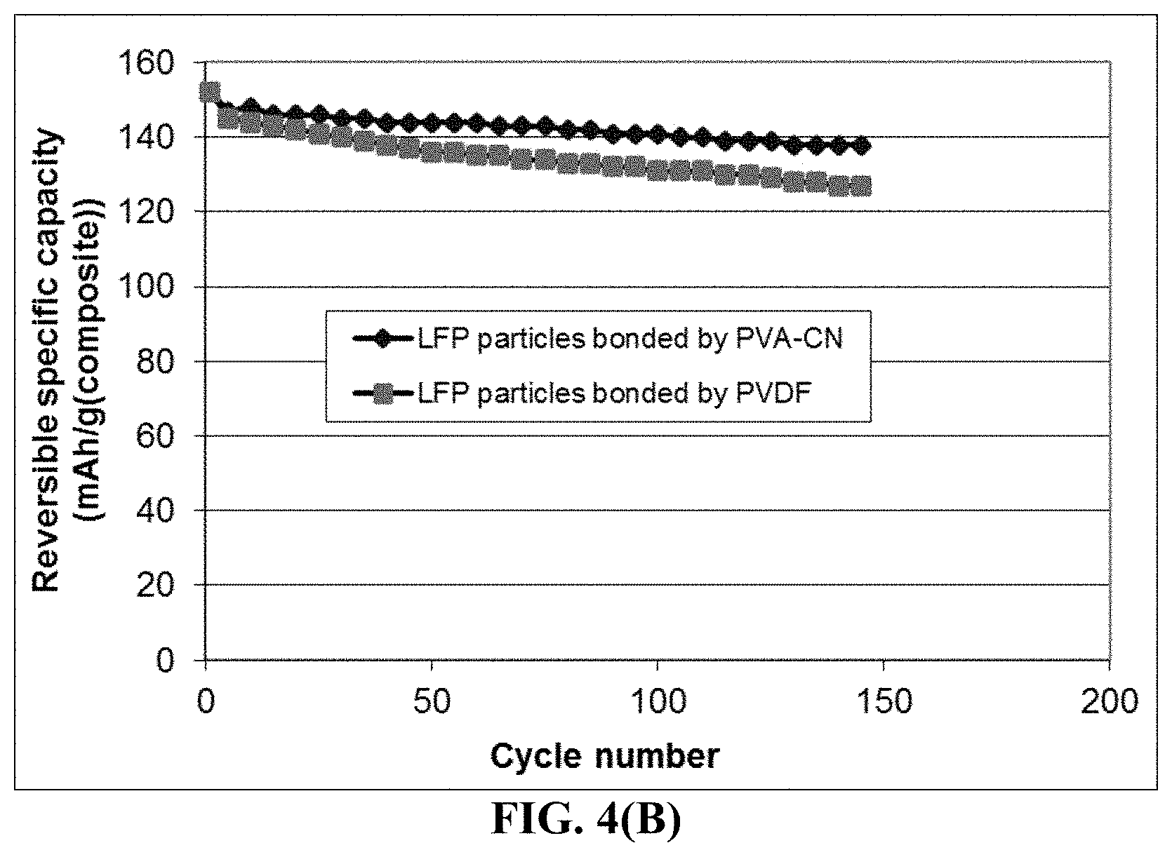
FIG. 4(B) The specific capacity values of two lithium battery cells having a cathode active material featuring (1) high-elasticity PVA-CN polymer binder-bonded LiFePO.sub.4 particles and (2) PVDF-bonded LiFePO.sub.4 particles, respectively.
FIG. 5(A) Representative tensile stress-strain curves of three cross-linked PETEA polymers
FIG. 5(B) discharge capacity curves of three coin cells having three different types of cathode active layers: (1) high-elasticity PETEA polymer binder-bonded, fluoride particles, (2) PVDF binder-bonded fluoride particles; and (3) SBR rubber-bonded, fluoride particles.
FIG. 6 Specific capacities of 2 lithium-FePc (organic) cells each having Li as an anode active material and FePc/RGO as the cathode active material. One of the cells has the cathode active layer protected by a thin film of cross-linked ETPTA/EGMEA polymer.
DESCRIPTION OF THE PREFERRED EMBODIMENTS
This invention is directed at the anode active material layer (negative electrode layer, not including the anode current collector) containing a high-capacity anode material for a lithium secondary battery, which is preferably a secondary battery based on a non-aqueous electrolyte, a polymer gel electrolyte, an ionic liquid electrolyte, a quasi-solid electrolyte, or a solid-state electrolyte. The shape of a lithium secondary battery can be cylindrical, square, button-like, etc. The present invention is not limited to any battery shape or configuration or any type of electrolyte. For convenience, we will primarily use Si, Sn, and SnO.sub.2 as illustrative examples of a high-capacity anode active material. This should not be construed as limiting the scope of the invention.
As illustrated in FIG. 1(B), a lithium-ion battery cell is typically composed of an anode current collector (e.g. Cu foil), an anode or negative electrode active material layer (i.e. anode layer typically containing particles of an anode active material, conductive additive, and binder), a porous separator and/or an electrolyte component, a cathode or positive electrode active material layer (containing a cathode active material, conductive additive, and resin binder), and a cathode current collector (e.g. Al foil). More specifically, the anode layer is composed of particles of an anode active material (e.g. graphite, Sn, SnO.sub.2, or Si), a conductive additive (e.g. carbon black particles), and a resin binder (e.g. SBR or PVDF). This anode layer is typically 50-300 .mu.m thick (more typically 100-200 .mu.m) to give rise to a sufficient amount of current per unit electrode area. Similarly, the cathode layer is composed of particles of a cathode active material (e.g. LiCoO.sub.2, LiMnO.sub.4, LiFePO.sub.4, etc.), a conductive additive (e.g. carbon black particles), and a resin binder (e.g. PVDF or PTFE). This cathode layer is typically 100-300 .mu.m thick.
In a less commonly used cell configuration, as illustrated in FIG. 1(A), the anode active material is deposited in a thin film form directly onto an anode current collector, such as a layer of Si coating deposited on a sheet of copper foil. If a layer of Li coating or Li foil is used as the anode active material, the battery is a lithium metal battery, lithium sulfur battery, lithium-air battery, lithium-selenium battery, etc.
In order to obtain a higher energy density cell, the anode in FIG. 1(B) can be designed to contain higher-capacity anode active materials having a composition formula of Li.sub.aA (A is a metal or semiconductor element, such as Al and Si, and "a" satisfies 0<a.ltoreq.5). These materials are of great interest due to their high theoretical capacity, e.g., Li.sub.4Si (3,829 mAh/g), Li.sub.4.4Si (4,200 mAh/g), Li.sub.4.4Ge (1,623 mAh/g), Li.sub.4.4Sn (993 mAh/g), Li.sub.3Cd (715 mAh/g), Li.sub.3Sb (660 mAh/g), Li.sub.4.4Pb (569 mAh/g), LiZn (410 mAh/g), and Li.sub.3Bi (385 mAh/g).
As schematically illustrated in FIG. 2, one major problem in the current lithium battery is the notion that binder resin can easily detach from the active material particles and conductive additive particles due to volume expansion/shrinkage of active material particles during the charge and discharge cycles when lithium ions are inserted into or extracted from the active material particles. The expansion and contraction of the active material particles can also lead to the pulverization of active material particles. These binder detachment and particle fragmentation phenomena lead to loss of contacts between active material particles and conductive additives and loss of contacts between the anode active material and its current collector. These adverse effects result in a significantly shortened charge-discharge cycle life.
We have solved these challenging issues that have troubled battery designers and electrochemists alike for more than 30 years by developing a new class of binder resin to hold the particles of the active material and conductive additive together.
The cathode active material layer comprises multiple cathode active material particles and conductive additive particles that are bonded together by a high-elasticity polymer having a recoverable tensile strain no less than 5% when measured without an additive or reinforcement in the polymer under uniaxial tension and a lithium ion conductivity no less than 10.sup.-5 S/cm at room temperature (preferably and more typically no less than 10.sup.-4 S/cm and more preferably and typically no less than 10.sup.-3 S/cm).
High-elasticity polymer refers to a polymer, typically a lightly cross-linked polymer, which exhibits an elastic deformation that is at least 5% when measured (without an additive or reinforcement in the polymer) under uniaxial tension. In the field of materials science and engineering, the "elastic deformation" is defined as a deformation of a material (when being mechanically stressed) that is essentially fully recoverable and the recovery is essentially instantaneous upon release of the load. The elastic deformation is preferably greater than 10%, more preferably greater than 30%, further more preferably greater than 50%, still more preferably greater than 100%, and most preferably greater than 200%. The preferred types of high-capacity polymers will be discussed later.
The application of the presently invented high-elasticity polymer binder approach is not limited to any particular class of cathode active materials. The cathode active material layer may contain a cathode active material selected from an inorganic material, an organic material, a polymeric material, or a combination thereof. The inorganic material may be selected from a metal oxide, metal phosphate, metal silicide, metal selenide, transition metal sulfide, or a combination thereof.
The inorganic material may be selected from a lithium cobalt oxide, lithium nickel oxide, lithium manganese oxide, lithium vanadium oxide, lithium-mixed metal oxide, lithium iron phosphate, lithium manganese phosphate, lithium vanadium phosphate, lithium mixed metal phosphate, lithium metal silicide, or a combination thereof.
In certain preferred embodiments, the inorganic material is selected from a metal fluoride or metal chloride including the group consisting of CoF.sub.3, MnF.sub.3, FeF.sub.3, VF.sub.3, VOF.sub.3, TiF.sub.3, BiF.sub.3, NiF.sub.2, FeF.sub.2, CuF.sub.2, CuF, SnF.sub.2, AgF, CuCl.sub.2, FeCl.sub.3, MnCl.sub.2, and combinations thereof. In certain preferred embodiments, the inorganic material is selected from a lithium transition metal silicate, denoted as Li.sub.2MSiO.sub.4 or Li.sub.2Ma.sub.xMb.sub.ySiO.sub.4, wherein M and Ma are selected from Fe, Mn, Co, Ni, V, or VO; Mb is selected from Fe, Mn, Co, Ni, V, Ti, Al, B, Sn, or Bi; and x+y.ltoreq.1.
In certain preferred embodiments, the inorganic material is selected from a transition metal dichalcogenide, a transition metal trichalcogenide, or a combination thereof. The inorganic material is selected from TiS.sub.2, TaS.sub.2, MoS.sub.2, NbSe.sub.3, MnO.sub.2, CoO.sub.2, an iron oxide, a vanadium oxide, or a combination thereof.
The cathode active material layer may contain a metal oxide containing vanadium oxide selected from the group consisting of VO.sub.2, Li.sub.xVO.sub.2, V.sub.2O.sub.5, Li.sub.xV.sub.2O.sub.5, V.sub.3O.sub.8, Li.sub.xV.sub.3O.sub.8, Li.sub.xV.sub.3O.sub.7, V.sub.4O.sub.9, Li.sub.xV.sub.4O.sub.9, V.sub.6O.sub.13, Li.sub.8V.sub.6O.sub.13, their doped versions, their derivatives, and combinations thereof, wherein 0.1<x<5.
The cathode active material layer may contain a metal oxide or metal phosphate, selected from a layered compound LiMO.sub.2, spinel compound LiM.sub.2O.sub.4, olivine compound LiMPO.sub.4, silicate compound Li.sub.2MSiO.sub.4, Tavorite compound LiMPO.sub.4F, borate compound LiMBO.sub.3, or a combination thereof, wherein M is a transition metal or a mixture of multiple transition metals.
In some embodiments, the inorganic material is selected from: (a) bismuth selenide or bismuth telluride, (b) transition metal dichalcogenide or trichalcogenide, (c) sulfide, selenide, or telluride of niobium, zirconium, molybdenum, hafnium, tantalum, tungsten, titanium, cobalt, manganese, iron, nickel, or a transition metal; (d) boron nitride, or (e) a combination thereof.
The cathode active material layer may contain an organic material or polymeric material selected from Poly(anthraquinonyl sulfide) (PAQS), a lithium oxocarbon, 3,4,9,10-perylenetetracarboxylic dianhydride (PTCDA), poly(anthraquinonyl sulfide), pyrene-4,5,9,10-tetraone (PYT), polymer-bound PYT, Quino(triazene), redox-active organic material, Tetracyanoquinodimethane (TCNQ), tetracyanoethylene (TCNE), 2,3,6,7,10,11-hexamethoxytriphenylene (HMTP), poly(5-amino-1,4-dyhydroxy anthraquinone) (PADAQ), phosphazene disulfide polymer ([(NPS.sub.2).sub.3]n), lithiated 1,4,5,8-naphthalenetetraol formaldehyde polymer, Hexaazatrinaphtylene (HATN), Hexaazatriphenylene hexacarbonitrile (HAT(CN).sub.6), 5-Benzylidene hydantoin, Isatine lithium salt, Pyromellitic diimide lithium salt, tetrahydroxy-p-benzoquinone derivatives (THQLi.sub.4), N,N'-diphenyl-2,3,5,6-tetraketopiperazine (PHP), N,N'-diallyl-2,3,5,6-tetraketopiperazine (AP), N,N'-dipropyl-2,3,5,6-tetraketopiperazine (PRP), a thioether polymer, a quinone compound, 1,4-benzoquinone, 5,7,12,14-pentacenetetrone (PT), 5-amino-2,3-dihydro-1,4-dyhydroxy anthraquinone (ADDAQ), 5-amino-1,4-dyhydroxy anthraquinone (ADAQ), calixquinone, Li.sub.4C.sub.6O.sub.6, Li.sub.2C.sub.6O.sub.6, Li.sub.6C.sub.6O.sub.6, or a combination thereof.
The thioether polymer is selected from Poly[methanetetryl-tetra(thiomethylene)] (PMTTM), Poly(2,4-dithiopentanylene) (PDTP), a polymer containing Poly(ethene-1,1,2,2-tetrathiol) (PETT) as a main-chain thioether polymers, a side-chain thioether polymer having a main-chain consisting of conjugating aromatic moieties, and having a thioether side chain as a pendant, Poly(2-phenyl-1,3-dithiolane) (PPDT), Poly(1,4-di(1,3-dithiolan-2-yl)benzene) (PDDTB), poly(tetrahydrobenzodithiophene) (PTHBDT), poly[1,2,4,5-tetrakis(propylthio)benzene] (PTKPTB, or poly[3,4(ethylenedithio)thiophene] (PEDTT).
In other embodiments, the cathode active material layer contains an organic material selected from a phthalocyanine compound, such as copper phthalocyanine, zinc phthalocyanine, tin phthalocyanine, iron phthalocyanine, lead phthalocyanine, nickel phthalocyanine, vanadyl phthalocyanine, fluorochromium phthalocyanine, magnesium phthalocyanine, manganous phthalocyanine, dilithium phthalocyanine, aluminum phthalocyanine chloride, cadmium phthalocyanine, chlorogallium phthalocyanine, cobalt phthalocyanine, silver phthalocyanine, a metal-free phthalocyanine, a chemical derivative thereof, or a combination thereof.
The particles of the anode active material may be in the form of a nano particle, nano wire, nano fiber, nano tube, nano sheet, nano platelet, nano disc, nano belt, nano ribbon, or nano horn. They can be non-lithiated (when incorporated into the anode active material layer) or pre-lithiated to a desired extent (up to the maximum capacity as allowed for a specific element or compound.
Preferably and typically, the high-elasticity polymer has a lithium ion conductivity no less than 10.sup.-5 S/cm, more preferably no less than 10.sup.-4 S/cm, further preferably no less than 10.sup.-3 S/cm, and most preferably no less than 10.sup.-2 S/cm. In some embodiments, the high-elasticity polymer is a neat polymer having no additive or filler dispersed therein. In others, the high-elasticity polymer is a polymer matrix composite containing from 0.1% to 50% (preferably 1% to 35%) by weight of a lithium ion-conducting additive dispersed in a high-elasticity polymer matrix material. The high-elasticity polymer must have a high elasticity (elastic deformation strain value >10%). An elastic deformation is a deformation that is fully recoverable and the recovery process is essentially instantaneous (no significant time delay). The high-elasticity polymer can exhibit an elastic deformation from 10% up to 1,000% (10 times of its original length), more typically from 10% to 800%, and further more typically from 50% to 500%, and most typically and desirably from 70% to 300%. It may be noted that although a metal typically has a high ductility (i.e. can be extended to a large extent without breakage), the majority of the deformation is plastic deformation (non-recoverable) and only a small amount of elastic deformation (typically <1% and more typically <0.2%).
In some preferred embodiments, the high-elasticity polymer contains a lightly cross-linked network polymer chains having an ether linkage, nitrile-derived linkage, benzo peroxide-derived linkage, ethylene oxide linkage, propylene oxide linkage, vinyl alcohol linkage, cyano-resin linkage, triacrylate monomer-derived linkage, tetraacrylate monomer-derived linkage, or a combination thereof, in the cross-linked network of polymer chains. These network or cross-linked polymers exhibit a unique combination of a high elasticity (high elastic deformation strain) and high lithium-ion conductivity.
In certain preferred embodiments, the high-elasticity polymer contains a lightly cross-linked network polymer chains selected from nitrile-containing polyvinyl alcohol chains, cyanoresin chains, pentaerythritol tetraacrylate (PETEA) chains, pentaerythritol triacrylate chains, ethoxylated trimethylolpropane triacrylate (ETPTA) chains, ethylene glycol methyl ether acrylate (EGMEA) chains, or a combination thereof.
Typically, a high-elasticity polymer is originally in a monomer or oligomer states that can be cured to form a cross-linked polymer that is highly elastic. Prior to curing, these polymers or oligomers are soluble in an organic solvent to form a polymer solution. Particles of a cathode active material (e.g. lithium metal oxide, lithium metal fluoride, etc.) can be dispersed in this polymer solution to form a suspension (dispersion or slurry. This suspension can then be coated onto a current collector surface (e.g. Cu foil, which is then subjected to a solvent removal treatment. The polymer (or monomer or oligomer) precipitates out to deposit on surfaces of these active material particles near the points of contact between particles. The concentration of the polymer precursor (monomer or oligomer) in the solution may be controlled to the extent that the polymer covers only less than 50% of the active material particles. In other words, the polymer is a binder resin that bond particles together, but does not encapsulate the particles.
For instance, ethoxylated trimethylopropane triacrylate monomer (ETPTA, Mw=428, chemical formula given below), along with an initiator, can be dissolved in an organic solvent, such as ethylene carbonate (EC) or diethyl carbonate (DEC). Then, cathode active material particles can be dispersed in the ETPTA monomer/solvent/initiator solution to form a slurry, which can be spray-coated onto an Al foil to form a cathode layer containing active particles partially coated by the ETPTA monomer/initiator. This layer is then thermally cured to obtain a cathode active layer of structural integrity, wherein the cathode active material particles and conductive additive particles are bonded together with a high-elasticity polymer binder. The polymerization and cross-linking reactions of this monomer can be initiated by a radical initiator derived from benzoyl peroxide (BPO) or AIBN through thermal decomposition of the initiator molecule. The ETPTA monomer has the following chemical formula:
##STR00001##
As another example, the high-elasticity polymer for encapsulation may be based on cationic polymerization and cross-linking of the cyanoethyl polyvinyl alcohol (PVA-CN, Formula 2) in succinonitrile (SN).
##STR00002##
The procedure may begin with dissolving PVA-CN in succinonitrile (NCCH.sub.2CH.sub.2CN) to form a mixture solution. This is followed by adding an initiator into the mixture solution. For instance, LiPF.sub.6 can be added into the PVA-CN/SN mixture solution at a weight ratio (selected from the preferred range from 20:1 to 2:1) to form a precursor solution. Then, particles of a selected cathode active material are introduced into the mixture solution to form a slurry. The slurry may then be coated onto a cathode current collector to form a cathode layer, wherein a reacting mass, PVA-CN/LiPF.sub.6, resides at interstitial spaces between particles. The cathode layer is then heated at a temperature (e.g. from 75 to 100.degree. C.) for 2 to 8 hours to obtain a cathode layer of structural integrity containing high-elasticity polymer-bonded active material particles and conductive additive particles. During this process, cationic polymerization and cross-linking of cyano groups on the PVA-CN may be initiated by PF.sub.5, which is derived from the thermal decomposition of LiPF.sub.6 at such an elevated temperature.
It is essential that the network polymer or cross-linked polymer has a relatively low degree of cross-linking or low cross-link density to impart a high elastic deformation.
The cross-link density of a cross-linked network of polymer chains may be defined as the inverse of the molecular weight between cross-links (Mc). The cross-link density can be determined by the equation, Mc=.rho.RT/Ge, where Ge is the equilibrium modulus as determined by a temperature sweep in dynamic mechanical analysis, .rho. is the physical density, R is the universal gas constant in J/mol*K and T is absolute temperature in K. Once Ge and p are determined experimentally, then Mc and the cross-link density can be calculated.
The magnitude of Mc may be normalized by dividing the Mc value by the molecular weight of the characteristic repeat unit in the cross-link chain or chain linkage to obtain a number, Nc, which is the number of repeating units between two cross-link points. We have found that the elastic deformation strain correlates very well with Mc and Nc. The elasticity of a cross-linked polymer derives from a large number of repeating units (large Nc) between cross-links. The repeating units can assume a more relax conformation (e.g. random coil) when the polymer is not stressed. However, when the polymer is mechanically stressed, the linkage chain uncoils or gets stretched to provide a large deformation. A long chain linkage between cross-link points (larger Nc) enables a larger elastic deformation. Upon release of the load, the linkage chain returns to the more relaxed or coiled state. During mechanical loading of a polymer, the cross-links prevent slippage of chains that otherwise form plastic deformation (non-recoverable).
Preferably, the Nc value in a high-elasticity polymer is greater than 5, more preferably greater than 10, further more preferably greater than 100, and even more preferably greater than 200. These Nc values can be readily controlled and varied to achieve different elastic deformation values by using different cross-linking agents with different functionalities, and by designing the polymerization and cross-linking reactions to proceed at different temperatures for different periods of time.
Alternatively, Mooney-Rilvin method may be used to determine the degree of cross-linking. Crosslinking also can be measured by swelling experiments. In a swelling experiment, the crosslinked sample is placed into a good solvent for the corresponding linear polymer at a specific temperature, and either the change in mass or the change in volume is measured. The higher the degree of crosslinking, the less swelling is attainable. Based on the degree of swelling, the Flory Interaction Parameter (which relates the solvent interaction with the sample, Flory Huggins Eq.), and the density of the solvent, the theoretical degree of crosslinking can be calculated according to Flory's Network Theory. The Flory-Rehner Equation can be useful in the determination of cross-linking.
The high-elasticity polymer may contain a simultaneous interpenetrating network (SIN) polymer, wherein two cross-linking chains intertwine with each other, or a semi-interpenetrating network polymer (semi-IPN), which contains a cross-linked polymer and a linear polymer. An example of semi-IPN is an UV-curable/polymerizable trivalent/monovalent acrylate mixture, which is composed of ethoxylated trimethylolpropane triacrylate (ETPTA) and ethylene glycol methyl ether acrylate (EGMEA) oligomers. The ETPTA, bearing trivalent vinyl groups, is a photo (UV)-crosslinkable monomer, capable of forming a network of cross-linked chains. The EGMEA, bearing monovalent vinyl groups, is also UV-polymerizable, leading to a linear polymer with a high flexibility due to the presence of the oligomer ethylene oxide units. When the degree of cross-linking of ETPTA is moderate or low, the resulting ETPTA/EGMEA semi-IPN polymer provides good mechanical flexibility or elasticity and reasonable mechanical strength. The lithium-ion conductivity of this polymer is in the range of 10.sup.-4 to 5.times.10.sup.-3 S/cm.
The aforementioned high-elasticity polymers may be used alone to chemically bond the cathode active material particles. Alternatively, the high-elasticity polymer can be mixed with a broad array of elastomers, electrically conducting polymers, lithium ion-conducting materials, and/or strengthening materials (e.g. carbon nanotube, carbon nano-fiber, or graphene sheets).
A broad array of elastomers can be mixed with a high-elasticity polymer to form a blend, co-polymer, or interpenetrating network that bonds the cathode active material particles together. The elastomeric material may be selected from natural polyisoprene (e.g. cis-1,4-polyisoprene natural rubber (NR) and trans-1,4-polyisoprene gutta-percha), synthetic polyisoprene (IR for isoprene rubber), polybutadiene (BR for butadiene rubber), chloroprene rubber (CR), polychloroprene (e.g. Neoprene, Baypren etc.), butyl rubber (copolymer of isobutylene and isoprene, IIR), including halogenated butyl rubbers (chloro butyl rubber (CIIR) and bromo butyl rubber (BIIR), styrene-butadiene rubber (copolymer of styrene and butadiene, SBR), nitrile rubber (copolymer of butadiene and acrylonitrile, NBR), EPM (ethylene propylene rubber, a copolymer of ethylene and propylene), EPDM rubber (ethylene propylene diene rubber, a terpolymer of ethylene, propylene and a diene-component), epichlorohydrin rubber (ECO), polyacrylic rubber (ACM, ABR), silicone rubber (SI, Q, VMQ), fluorosilicone rubber (FVMQ), fluoroelastomers (FKM, and FEPM; such as Viton, Tecnoflon, Fluorel, Aflas and Dai-El), perfluoroelastomers (FFKM: Tecnoflon PFR, Kalrez, Chemraz, Perlast), polyether block amides (PEBA), chlorosulfonated polyethylene (CSM; e.g. Hypalon), and ethylene-vinyl acetate (EVA), thermoplastic elastomers (TPE), protein resilin, protein elastin, ethylene oxide-epichlorohydrin copolymer, polyurethane, urethane-urea copolymer, and combinations thereof.
The urethane-urea copolymer film usually consists of two types of domains, soft domains and hard ones. Entangled linear backbone chains consisting of poly(tetramethylene ether) glycol (PTMEG) units constitute the soft domains, while repeated methylene diphenyl diisocyanate (MDI) and ethylene diamine (EDA) units constitute the hard domains. The lithium ion-conducting additive can be incorporated in the soft domains or other more amorphous zones.
In some embodiments, a high-elasticity polymer can form a polymer matrix composite containing a lithium ion-conducting additive dispersed in the high-elasticity polymer matrix material, wherein the lithium ion-conducting additive is selected from Li.sub.2CO.sub.3, Li.sub.2O, Li.sub.2C.sub.2O.sub.4, LiOH, LiX, ROCO.sub.2Li, HCOLi, ROLi, (ROCO.sub.2Li).sub.2, (CH.sub.2OCO.sub.2Li).sub.2, Li.sub.2S, Li.sub.xSO.sub.y, or a combination thereof, wherein X=F, Cl, I, or Br, R=a hydrocarbon group, x=0-1, y=1-4.
In some embodiments, the high-elasticity polymer can be mixed with a lithium ion-conducting additive, which contains a lithium salt selected from lithium perchlorate, LiClO.sub.4, lithium hexafluorophosphate, LiPF.sub.6, lithium borofluoride, LiBF.sub.4, lithium hexafluoroarsenide, LiAsF.sub.6, lithium trifluoro-metasulfonate, LiCF.sub.3SO.sub.3, bis-trifluoromethyl sulfonylimide lithium, LiN(CF.sub.3SO.sub.2).sub.2, lithium bis(oxalato)borate, LiBOB, lithium oxalyldifluoroborate, LiBF.sub.2C.sub.2O.sub.4, lithium oxalyldifluoroborate, LiBF.sub.2C.sub.2O.sub.4, lithium nitrate, LiNO.sub.3, Li-Fluoroalkyl-Phosphates, LiPF.sub.3(CF.sub.2CF.sub.3).sub.3, lithium bisperfluoro-ethysulfonylimide, LiBETI, lithium bis(trifluoromethanesulphonyl)imide, lithium bis(fluorosulphonyl)imide, lithium trifluoromethanesulfonimide, LiTFSI, an ionic liquid-based lithium salt, or a combination thereof.
The high-elasticity polymer may form a mixture, blend, or semi-interpenetrating network with an electron-conducting polymer selected from polyaniline, polypyrrole, polythiophene, polyfuran, a bi-cyclic polymer, derivatives thereof (e.g. sulfonated versions), or a combination thereof.
In some embodiments, the high-elasticity polymer may form a mixture, co-polymer, or semi-interpenetrating network with a lithium ion-conducting polymer selected from poly(ethylene oxide) (PEO), Polypropylene oxide (PPO), poly(acrylonitrile) (PAN), poly(methyl methacrylate) (PMMA), poly(vinylidene fluoride) (PVdF), Poly bis-methoxy ethoxyethoxide-phosphazenex, Polyvinyl chloride, Polydimethylsiloxane, poly(vinylidene fluoride)-hexafluoropropylene (PVDF-HFP), a derivative thereof (e.g. sulfonated versions), or a combination thereof.
Unsaturated rubbers that can be mixed with the high-elasticity polymer include natural polyisoprene (e.g. cis-1,4-polyisoprene natural rubber (NR) and trans-1,4-polyisoprene gutta-percha), synthetic polyisoprene (IR for isoprene rubber), polybutadiene (BR for butadiene rubber), chloroprene rubber (CR), polychloroprene (e.g. Neoprene, Baypren etc.), butyl rubber (copolymer of isobutylene and isoprene, IIR), including halogenated butyl rubbers (chloro butyl rubber (CIIR) and bromo butyl rubber (BIIR), styrene-butadiene rubber (copolymer of styrene and butadiene, SBR), nitrile rubber (copolymer of butadiene and acrylonitrile, NBR),
Some elastomers are saturated rubbers that cannot be cured by sulfur vulcanization; they are made into a rubbery or elastomeric material via different means: e.g. by having a copolymer domain that holds other linear chains together. Each of these elastomers can be used to bond particles of a cathode active material by one of several means; e.g. spray coating, dilute solution mixing (dissolving the cathode active material particles in an uncured polymer, monomer, or oligomer, with or without an organic solvent) followed by drying and curing.
Saturated rubbers and related elastomers in this category include EPM (ethylene propylene rubber, a copolymer of ethylene and propylene), EPDM rubber (ethylene propylene diene rubber, a terpolymer of ethylene, propylene and a diene-component), epichlorohydrin rubber (ECO), polyacrylic rubber (ACM, ABR), silicone rubber (SI, Q, VMQ), fluorosilicone rubber (FVMQ), fluoroelastomers (FKM, and FEPM; such as Viton, Tecnoflon, Fluorel, Aflas and Dai-El), perfluoroelastomers (FFKM: Tecnoflon PFR, Kalrez, Chemraz, Perlast), polyether block amides (PEBA), chlorosulfonated polyethylene (CSM; e.g. Hypalon), and ethylene-vinyl acetate (EVA), thermoplastic elastomers (TPE), protein resilin, and protein elastin. Polyurethane and its copolymers (e.g. urea-urethane copolymer) are particularly useful elastomeric shell materials for encapsulating anode active material particles.
The binder formulation typically requires the high-elasticity polymer or its precursor (monomer or oligomer) to be dissolvable in a solvent. Fortunately, all the high-elasticity polymers or their precursors used herein are soluble in some common solvents. The un-cured polymer or its precursor can be readily dissolved in a common organic solvent to form a solution. This solution can then be used to bond solid particles via several of the binder application methods to be discussed in what follows. Upon contact with active material particles, the precursor is then polymerized and cross-linked. Since the high-elasticity polymer is initially in an uncured or un-polymerized state prior to being brought in contact with the active material particles for electrode fabrication, the chemically active groups or chains are capable of forming various strong chemical bonds (other than or in addition to the van der Waals forces) with the active material particles. In contrast, all the prior art resin binders have been already polymerized or cured before contacting the active material particles; hence, only weak van der Waals forces are formed between the conventional binder resin and the active material particles.
The first method includes dispersing the cathode active materials particles into the polymer precursor solution to form a slurry, which is then coated onto a surface of a current collector (e.g. Al foil). The liquid medium of the coated slurry is then removed to form a dried layer containing the active material particles and conductive additive particles each partially coated with the polymer pre-cursor (monomer or oligomer). This procedure is essentially identical or very similar to the slurry coating process currently commonly used in lithium-ion battery. Hence, there is no need to change the production equipment or facility. This dried layer is exposed to heat and/or UV light to initiate the polymerization and cross-linking reactions that harden the binder resin and chemically bonds the solid particles together. Preferably, the amount of polymer is selected in such a manner that the binder resin only covers less than 50% (preferably <20%) of the exterior surface of an active material particle.
One may also use a modified pan coating process that involves tumbling the active material particles in a pan or a similar device while the precursor solution is applied slowly until a desired amount of contact between the polymer precursor and solid active material particles is achieved. The concentration of the monomer/oligomer in the solution is selected to ensure a sufficient amount of polymer being present to help bond the active particles together, but not to cover the entire exterior surface of active material particles. Preferably, a majority of the exterior surface of an active material particle is not covered by the polymer.
Solution spraying also may be used to apply a binder resin to surfaces of active material particles supported by a solid substrate. The polymer precursor solution, along with particles of active material and conductive additive, may be spray-coated onto a surface of a current collector. Upon removal of the liquid solvent, the dried mass is subjected to thermally or UV-induced polymerization and cross-linking.
Example 1: Cathode Active Material Layers Containing High-Elasticity Polymer-Bonded V.sub.2O.sub.5 Particles
Cathode active material layers were prepared from V.sub.2O.sub.5 particles and graphene-embraced V.sub.2O.sub.5 particles, respectively. V.sub.2O.sub.5 particles were commercially available. Graphene-embraced V.sub.2O.sub.5 particles were prepared in-house. In a typical experiment, vanadium pentoxide gels were obtained by mixing V.sub.2O.sub.5 in a LiCl aqueous solution. The Lit exchanged gels obtained by interaction with LiCl solution (the Li:V molar ratio was kept as 1:1) was mixed with a GO suspension and then placed in a Teflon-lined stainless steel 35 ml autoclave, sealed, and heated up to 180.degree. C. for 12 h. After such a hydrothermal treatment, the green solids were collected, thoroughly washed, ultrasonicated for 2 minutes, and dried at 70.degree. C. for 12 h followed by mixing with another 0.1% GO in water, ultrasonicating to break down nano-belt sizes, and then spray-drying at 200.degree. C. to obtain graphene-embraced V.sub.2O.sub.5 composite particulates.
Selected amounts of V.sub.2O.sub.5 particles and graphene-embraced V.sub.2O.sub.5 particles, respectively, were then each made into a cathode active material layer using an ETPTA-based high-elasticity polymer binder according to the following procedure: The ethoxylated trimethylopropane triacrylate monomer (ETPTA, Mw=428, Sigma-Aldrich) was dissolved in a solvent mixture of ethylene carbonate (EC)/diethyl carbonate (DEC), at a weight-based composition ratios of the ETPTA/solvent of 3/97 (w/w). Subsequently, benzoyl peroxide (BPO, 1.0 wt. % relative to the ETPTA content) was added as a radical initiator to allow for thermal crosslinking reaction after mixing with anode particles. Then, cathode active material particles and some CNTs (as a conductive additive) were dispersed in the ETPTA monomer/solvent/initiator solution to form a slurry, which was spray-coated onto a Cu foil surface to form a layer of mixture of ETPTA monomer/initiator, CNTs, and cathode particles. This layer was then thermally cured at 60.degree. C. for 30 min to obtain a cathode active material layer composed of V.sub.2O.sub.5 particles or graphene-embraced V.sub.2O.sub.5 particles and CNTs that are bonded together by a high-elasticity polymer-based binder resin.
On a separate basis, some amount of the ETPTA monomer/solvent/initiator solution was cast onto a glass surface to form a wet film, which was thermally dried and then cured at 60.degree. C. for 30 min to form a film of cross-linked polymer. In this experiment, the BPO/ETPTA weight ratio was varied from 0.1% to 4% to vary the degree of cross-linking in several different polymer films. Some of the cure polymer samples were subjected to dynamic mechanical testing to obtain the equilibrium dynamic modulus, Ge, for the determination of the number average molecular weight between two cross-link points (Mc) and the corresponding number of repeat units (Nc), as a means of characterizing the degree of cross-linking.
Several tensile testing specimens were cut from each cross-link film and tested with a universal testing machine. The representative tensile stress-strain curves of four BPO-initiated cross-linked ETPTA polymers are shown in FIG. 3(A), which indicate that this series of network polymers have an elastic deformation from approximately 230% to 700%. These above are for neat polymers without any additive. The addition of up to 30% by weight of a lithium salt typically reduces this elasticity down to a reversible tensile strain from 10% to 100%.
For electrochemical testing, a comparative electrode using a conventional binder resin is also prepared. The working electrodes were prepared by mixing 85 wt. % V.sub.2O.sub.5 or 88% of graphene-embraced V.sub.2O.sub.5 particles), 5-8 wt. % CNTs, and 7 wt. % polyvinylidene fluoride (PVDF) binder dissolved in N-methyl-2-pyrrolidinoe (NMP) to form a slurry of 3 wt. % total solid content. After coating the slurries on Al foil, the electrodes were dried at 120.degree. C. in vacuum for 2 h to remove the solvent before pressing. Then, the electrodes were cut into a disk (.PHI.=12 mm) and dried at 100.degree. C. for 24 h in vacuum.
Electrochemical measurements were carried out using CR2032 (3V) coin-type cells with lithium metal as the counter/reference electrode, Celgard 2400 membrane as separator, and 1 M LiPF.sub.6 electrolyte solution dissolved in a mixture of ethylene carbonate (EC) and diethyl carbonate (DEC) (EC-DEC, 1:1 v/v). The cell assembly was performed in an argon-filled glove-box. The CV measurements were carried out using a CH-6 electrochemical workstation at a scanning rate of 1 mV/s. The electrochemical performance of the cell featuring high-elasticity polymer binder and that containing PVDF binder were evaluated by galvanostatic charge/discharge cycling at a current density of 50 mA/g using an Arbin electrochemical workstation.
Summarized in FIG. 3(B) are the specific intercalation capacity curves of four lithium cells: cathode containing PVDF-bonded V.sub.2O.sub.5 particles, cathode containing PVDF-bonded graphene-embraced V.sub.2O.sub.5 particles, cathode containing ETPTA polymer-bonded V.sub.2O.sub.5 particles, and cathode containing ETPTA polymer-bonded graphene-embraced V.sub.2O.sub.5 particles. As the number of cycles increases, the specific capacity of the PVDF-bonded V.sub.2O.sub.5 electrode drops at the fastest rate. In contrast, the presently invented high-elasticity polymer binder provides the battery cell with a significantly more stable and high specific capacity for a large number of cycles. These data have clearly demonstrated the surprising and superior performance of the presently invented high-elasticity polymer binder.
The high-elasticity polymer binder appears to be capable of reversibly deforming to a great extent without breakage when the active material particles expand and shrink. The polymer also remains chemically bonded to the active material particles when these particles expand or shrink. In contrast, the PVDF binder is broken or detached from some of the active material particles. These were observed by using SEM to examine the surfaces of the electrodes recovered from the battery cells after some numbers of charge-discharge cycles.
Example 2: High-Elasticity Polymer Binder-Bonded Lithium Iron Phosphate (LFP) Particles
The high-elasticity polymer as a binder for chemically bonding LFP particles was based on cationic polymerization and cross-linking of the cyanoethyl polyvinyl alcohol (PVA-CN) in succinonitrile (SN). The procedure began with dissolving PVA-CN in succinonitrile to form a mixture solution. This step was followed by adding an initiator into the solution. For the purpose of incorporating some lithium species into the high elasticity polymer, we chose to use LiPF.sub.6 as an initiator. The ratio between LiPF.sub.6 and the PVA-CN/SN mixture solution was varied from 1/20 to 1/2 by weight to form a series of precursor solutions. Subsequently, carbon-coated LFP particles and acetylene black particles (as a conductive additive) were introduced into these solutions to form a series of slurries. The slurries were then separately coated onto an Al foil surface to produce a cathode active material layer. The layer was then heated at a temperature from 75 to 100.degree. C. for 2 to 8 hours to obtain a layer of high-elasticity polymer-bonded cathode active material particles.
Additionally, the reacting mass, PVA-CN/LiPF.sub.6, was cast onto a glass surface to form several films which were polymerized and cross-linked to obtain cross-linked polymers having different degrees of cross-linking. Tensile testing was also conducted on these films and some testing results are summarized in FIG. 4(A). This series of cross-linked polymers can be elastically stretched up to approximately 80% (higher degree of cross-linking) to 400% (lower degree of cross-linking).
The battery cells from the high-elasticity polymer-bonded LFP particles and PVDF-bonded LFP particles were prepared using a procedure described in Example 1. FIG. 4(B) shows that the cathode prepared according to the presently invented high-elasticity polymer binder approach offers a significantly more stable cycling behavior and higher reversible capacity compared to the PVDF-bonded LFP particle-based cathode. The high-elasticity polymer is more capable of holding the active material particles and conductive additive together, significantly improving the structural integrity of the active material electrode.
Example 3: Metal Fluoride Nano Particles Bonded by a PETEA-Based High-Elasticity Polymer
For serving as a resin binder to bond FeF.sub.3 nano particles together, pentaerythritol tetraacrylate (PETEA), Formula 3, was used as a monomer:
##STR00003##
Commercially available powders of CoF.sub.3, MnF.sub.3, FeF.sub.3, VF.sub.3, VOF.sub.3, TiF.sub.3, and BiF.sub.3 were subjected to high-intensity ball-milling to reduce the particle size down to approximately 0.5-2.3 .mu.m. Each type of these metal fluoride particles, along with graphene sheets (as a conductive additive), was then added into a PETEA monomer liquid suspension to form a multiple-component slurry. The slurry was cast into a wet layer onto a surface of Al foil, which was followed by liquid removal to form a dried layer. The dried layer was then compressed into a consolidated layer. The amount of PETEA was selected in such a manner that the fluoride particle surfaces were not fully covered; instead, only up to 50% was coated.
In a representative procedure, the precursor solution was composed of 1.5 wt. % PETEA (C.sub.17H.sub.20O.sub.8) monomer and 0.1 wt. % azodiisobutyronitrile (AIBN, C.sub.8H.sub.12N.sub.4) initiator dissolved in a solvent mixture of 1,2-dioxolane (DOL)/dimethoxymethane (DME)(1:1 by volume). The PETEA/AIBN precursor solution was polymerized and cured at 70.degree. C. for half an hour to obtain a cathode active layer.
Additionally, the reacting mass, PETEA/AIBN (without active particles and conductive additive), was cast onto a glass surface to form several films which were polymerized and cured to obtain cross-linked polymers having different degrees of cross-linking. Tensile testing was also conducted on these films and some testing results are summarized in FIG. 5(A). This series of cross-linked polymers can be elastically stretched up to approximately 25% (higher degree of cross-linking) to 80% (lower degree of cross-linking)
For comparison, some amount of metal fluoride particles was bonded by SBR binder to make an electrode. Shown in FIG. 5(B) are the discharge capacity curves of three coin cells having three different types of cathode active layers: (1) high-elasticity PETEA polymer binder-bonded metal fluoride particles, (2) PVDF binder-bonded metal fluoride particles; and (3) SBR rubber-bonded metal fluoride particles. These results have clearly demonstrated that the high-elasticity polymer binder strategy provides excellent protection against capacity decay of a lithium metal battery featuring a high-capacity cathode active material (with or without graphene coating).
The high-elasticity polymer binder appears to be capable of reversibly deforming without breakage when the anode active material particles expand and shrink. The polymer also remains chemically bonded to the cathode active material particles when these particles expand or shrink. In contrast, both SBR and PVDF, the two conventional binder resins, are broken or detached from some of the active material particles. These were observed by using SEM to examine the surfaces of the electrodes recovered from the battery cells after some numbers of charge-discharge cycles.
Example 4: Metal Naphthalocyanine-Reduced Graphene Oxide (FePc/RGO) Hybrid Particulates Protected by a Layer of High-Elasticity Polymer
Particles of FePc/graphene sheets were obtained by ball-milling a mixture of FePc and RGO in a milling chamber for 30 minutes. The potato-shape FePc/RGO mixture particles were then bonded by a PVDF binder to form a cathode active layer on Al foil surface. Two lithium cells were prepared, each containing a Li foil anode, a porous separator, and a layer of FePc/RGO cathode. However, in one of the two cells, a thin film of a high-elasticity polymer was implemented between the porous separator and the cathode layer. This was accomplished by spraying a film of semi-interpenetrating network polymer of ETPTA/EGMEA onto a surface of a FePc/RGO mixture layer prior to being combined into a battery cell.
For preparation of this ETPTA semi-IPN polymer, the ETPTA (Mw=428 g/mol, trivalent acrylate monomer), EGMEA (Mw=482 g/mol, monovalent acrylate oligomer), and 2-hydroxy-2-methyl-1-phenyl-1-propanone (HMPP, a photoinitiator) were dissolved in a solvent (propylene carbonate, PC) to form a solution. The weight ratio between HMPP and the ETPTA/EGMEA mixture was varied from 0.2% to 2%. The ETPTA/EGMEA proportion in the solution was varied from 1% to 5% to generate different thin film thicknesses. The ETPTA/EGMEA ratio in the acrylate mixture was varied from 10/0 to 1/9.
The ETPTA/EGMEA/HMPP film was then exposed to UV irradiation for 20 s. The UV polymerization/cross-linking was conducted using a Hg UV lamp (100 W), having a radiation peak intensity of approximately 2000 mW/cm.sup.2 on the surfaces of the electrodes.
The above procedure was conducted to produce electrode layers that were protected by a thin film of cross-linked ETPTA/EGMEA polymer. The cycling behaviors of these 2 cells are shown in FIG. 6, which indicates that the lithium-organic cell having a high-elasticity polymer film-protected cathode layer exhibits a significantly more stable cycling response. This protective layer reduces or eliminates the direct contact between the catalytic transition metal element (Fe) and the electrolyte, yet still being permeable to lithium ions.
Example 5: Effect of Lithium Ion-Conducting Additive in a High-Elasticity Polymer Binder
A wide variety of lithium ion-conducting additives were added to several different polymer matrix materials to prepare binder resin materials for maintaining structural integrity of electrodes (Table 1). We have discovered that these polymer composite materials are suitable binder materials. Since the high-elasticity polymer can cover a significant portion of the active material particle surface, this polymer (with or without the lithium ion-conducting additive) must be capable of allowing lithium ions to readily diffuse through. Hence, the polymer must have a lithium ion conductivity at room temperature no less than 10.sup.-5 S/cm.
TABLE-US-00001 TABLE 1 Lithium ion conductivity of various high-elasticity polymer composite compositions as a shell material for protecting anode active material particles. Sample Lithium-conducting No. additive Elastomer (1-2 .mu.m thick) Li-ion conductivity (S/cm) E-1b Li.sub.2CO.sub.3 + (CH.sub.2OCO.sub.2Li).sub.2 70-99% PVA-CN 2.9 .times. 10.sup.-4 to 3.6 .times. 10.sup.-3 S/cm E-2b Li.sub.2CO.sub.3 + (CH.sub.2OCO.sub.2Li).sub.2 65-99% ETPTA 6.4 .times. 10.sup.-4 to 2.3 .times. 10.sup.-3 S/cm E-3b Li.sub.2CO.sub.3 + (CH.sub.2OCO.sub.2Li).sub.2 65-99% ETPTA/EGMEA 8.4 .times. 10.sup.-4 to 1.8 .times. 10.sup.-3 S/cm D-4b Li.sub.2CO.sub.3 + (CH.sub.2OCO.sub.2Li).sub.2 70-99% PETEA 7.8 .times. 10.sup.-3 to 2.3 .times. 10.sup.-2 S/cm D-5b Li.sub.2CO.sub.3 + (CH.sub.2OCO.sub.2Li).sub.2 75-99% PVA-CN 8.9 .times. 10.sup.-4 to 5.5 .times. 10.sup.-3 S/cm B1b LiF + LiOH + Li.sub.2C.sub.2O.sub.4 60-90% PVA-CN 8.7 .times. 10.sup.-5 to 2.3 .times. 10.sup.-3 S/cm B2b LiF + HCOLi 80-99% PVA-CN 2.8 .times. 10.sup.-4 to 1.6 .times. 10.sup.-3 S/cm B3b LiOH 70-99% PETEA 4.8 .times. 10.sup.-3 to 1.2 .times. 10.sup.-2 S/cm B4b Li.sub.2CO.sub.3 70-99% PETEA 4.4 .times. 10.sup.-3 to 9.9 .times. 10.sup.-3 S/cm B5b Li.sub.2C.sub.2O.sub.4 70-99% PETEA 1.3 .times. 10.sup.-3 to 1.2 .times. 10.sup.-2 S/cm B6b Li.sub.2CO.sub.3 + LiOH 70-99% PETEA 1.4 .times. 10.sup.-3 to 1.6 .times. 10.sup.-2 S/cm C1b LiClO.sub.4 70-99% PVA-CN 4.5 .times. 10.sup.-4 to 2.4 .times. 10.sup.-3 S/cm C2b LiPF.sub.6 70-99% PVA-CN 3.4 .times. 10.sup.-4 to 7.2 .times. 10.sup.-3 S/cm C3b LiBF.sub.4 70-99% PVA-CN 1.1 .times. 10.sup.-4 to 1.8 .times. 10.sup.-3 S/cm C4b LiBOB + LiNO.sub.3 70-99% PVA-CN 2.2 .times. 10.sup.-4 to 4.3 .times. 10.sup.-3 S/cm S1b Sulfonated polyaniline 85-99% ETPTA 9.8 .times. 10.sup.-5 to 9.2 .times. 10.sup.-4 S/cm S2b Sulfonated SBR 85-99% ETPTA 1.2 .times. 10.sup.-4 to 1.0 .times. 10.sup.-3 S/cm S3b Sulfonated PVDF 80-99% ETPTA/EGMEA 3.5 .times. 10.sup.-4 to 2.1 .times. 10.sup.-4 S/cm S4b Polyethylene oxide 80-99% ETPTA/EGMEA 4.9 .times. 10.sup.-4 to 3.7 .times. 103.sup.4 S/cm
Example 6: Cycle Stability of Various Rechargeable Lithium Battery Cells
In lithium-ion battery industry, it is a common practice to define the cycle life of a battery as the number of charge-discharge cycles that the battery suffers 20% decay in capacity based on the initial capacity measured after the required electrochemical formation. Summarized in Table 2 below are the cycle life data of a broad array of batteries featuring presently invented electrodes containing anode active material particles bonded by different binder materials.
TABLE-US-00002 TABLE 3 Cycle life data of various lithium secondary (rechargeable) batteries. Initial Cycle life Type & % of cathode active capacity (No. of Sample ID Binder resins material (mAh/g) cycles) CuCl.sub.2-1 PVA-CN 85% by wt. CuCl.sub.2 particles (80 530 650 nm) + 7% graphite + 8% binder CuCl.sub.2-2 SBR 85% by wt. CuCl.sub.2 particles (80 525 152 nm) + 7% graphite + 8% binder BiF.sub.3-1 SBR 85% by wt. BiFe.sub.3 particles + 7% 275 243 graphene + 8% binder BiF.sub.3-2 PVA-CN + 50% 85% by wt. BiFe.sub.3 particles + 7% 276 1,145 ethylene oxide graphene + 8% binder Li.sub.2MnSiO.sub.4-1 ETPTA 85% C-coated Li.sub.2MnSiO.sub.4 + 7% 252 1,440 CNT + 8% binder Li.sub.2MnSiO.sub.4-2 PVDF 85% C-coated Li.sub.2MnSiO.sub.4 + 7% 252 945 CNT + 8% binder Li.sub.6C.sub.6O.sub.6-1 ETPTA/EGMEA + Li.sub.6C.sub.6O.sub.6-graphene ball-milled 440 680 20% polyanniline Li.sub.6C.sub.6O.sub.6-2 PTFE Li.sub.6C.sub.6O.sub.6-graphene ball-milled 438 124 MoS.sub.2-1 PETEA 85% MoS.sub.2 + 8% graphite platelets + 225 552 binder MoS.sub.2-2 PVDF 85% MoS.sub.2 + 8% graphite platelets + 225 145 binder
These data further confirm that the high-elasticity polymer binder strategy is surprisingly effective in alleviating the cathode structural instability-induced capacity decay problems.
* * * * *
C00001
C00002
C00003
D00000
D00001
D00002
D00003
D00004
D00005
D00006
D00007
D00008
D00009

XML
uspto.report is an independent third-party trademark research tool that is not affiliated, endorsed, or sponsored by the United States Patent and Trademark Office (USPTO) or any other governmental organization. The information provided by uspto.report is based on publicly available data at the time of writing and is intended for informational purposes only.
While we strive to provide accurate and up-to-date information, we do not guarantee the accuracy, completeness, reliability, or suitability of the information displayed on this site. The use of this site is at your own risk. Any reliance you place on such information is therefore strictly at your own risk.
All official trademark data, including owner information, should be verified by visiting the official USPTO website at www.uspto.gov. This site is not intended to replace professional legal advice and should not be used as a substitute for consulting with a legal professional who is knowledgeable about trademark law.