Nitrogen-containing compound, organic electroluminescent device and photoelectric conversion device
Ma , et al. April 20, 2
U.S. patent number 10,985,324 [Application Number 16/872,748] was granted by the patent office on 2021-04-20 for nitrogen-containing compound, organic electroluminescent device and photoelectric conversion device. This patent grant is currently assigned to Shaanxi Lighte Optoelectronics Material Co., Ltd.. The grantee listed for this patent is Shaanxi Lighte Optoelectronics Material Co., Ltd.. Invention is credited to Zhen Feng, Hongyan Li, Tiantian Ma, Qiqi Nie, Xunshan Sha, Zhanyi Sun, Yalong Wang.


View All Diagrams
| United States Patent | 10,985,324 |
| Ma , et al. | April 20, 2021 |
Nitrogen-containing compound, organic electroluminescent device and photoelectric conversion device
Abstract
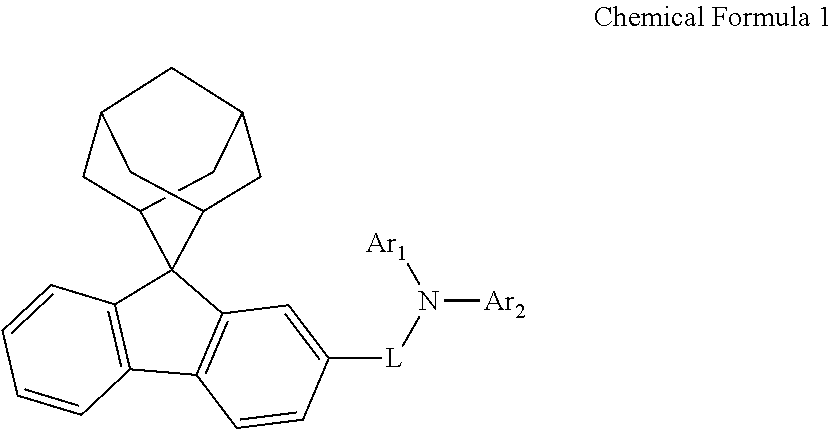
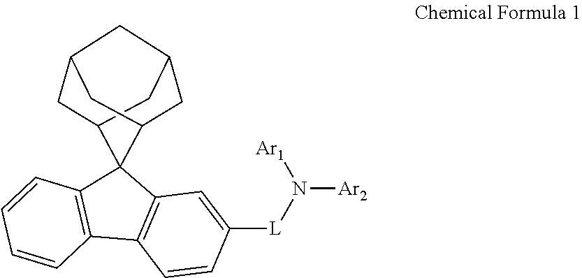
A nitrogen-containing compound, an organic electroluminescent device, and a photoelectric conversion device are provided, which relates to the technical field of electronic components. The nitrogen-containing compound has a structure represented by Chemical Formula 1. The organic electroluminescent device using the nitrogen-containing compound and the photoelectric conversion device using the nitrogen-containing compound can be improved. ##STR00001##
| Inventors: | Ma; Tiantian (Xi'an, CN), Nie; Qiqi (Xi'an, CN), Li; Hongyan (Xi'an, CN), Feng; Zhen (Xi'an, CN), Sun; Zhanyi (Xianyang, CN), Wang; Yalong (Xi'an, CN), Sha; Xunshan (Xi'an, CN) | ||||||||||
|---|---|---|---|---|---|---|---|---|---|---|---|
| Applicant: |
|
||||||||||
| Assignee: | Shaanxi Lighte Optoelectronics
Material Co., Ltd. (Shaanxi, CN) |
||||||||||
| Family ID: | 1000005501963 | ||||||||||
| Appl. No.: | 16/872,748 | ||||||||||
| Filed: | May 12, 2020 |
Prior Publication Data
| Document Identifier | Publication Date | |
|---|---|---|
| US 20200395544 A1 | Dec 17, 2020 | |
Foreign Application Priority Data
| Jun 14, 2019 [CN] | 201910515733.1 | |||
| Aug 15, 2019 [CN] | 201910755507.0 | |||
| Aug 19, 2019 [CN] | 201910765403.8 | |||
| Current U.S. Class: | 1/1 |
| Current CPC Class: | C07D 333/76 (20130101); H01L 51/006 (20130101); C07D 307/91 (20130101); H01L 51/0061 (20130101); C07D 209/86 (20130101); C07C 211/54 (20130101); C07C 211/61 (20130101); H01L 51/42 (20130101); H01L 51/5088 (20130101); H01L 51/0072 (20130101); C07C 2603/97 (20170501); H01L 51/0056 (20130101); H01L 51/5064 (20130101); C07C 2603/18 (20170501); H01L 51/0073 (20130101); H01L 51/0074 (20130101) |
| Current International Class: | C07C 211/54 (20060101); C07D 209/86 (20060101); C07D 307/91 (20060101); H01L 51/42 (20060101); H01L 51/50 (20060101); H01L 51/00 (20060101); C07D 333/76 (20060101); C07C 211/61 (20060101) |
| 103108859 | May 2013 | CN | |||
| 104583176 | Apr 2015 | CN | |||
| 106008424 | Oct 2016 | CN | |||
| 10745466 | Dec 2017 | CN | |||
| 107459466 | Dec 2017 | CN | |||
| 109438350 | Mar 2019 | CN | |||
| 110128279 | Aug 2019 | CN | |||
| 110467536 | Nov 2019 | CN | |||
| 20190035567 | Apr 2019 | KR | |||
| 20190118515 | Oct 2019 | KR | |||
| 102020037732 | Apr 2020 | KR | |||
| 1020200037732 | Apr 2020 | KR | |||
| 2020050023 | Mar 2020 | WO | |||
| 2020050623 | Mar 2020 | WO | |||
| 2020060271 | Mar 2020 | WO | |||
| 2020080849 | Apr 2020 | WO | |||
Other References
|
Machine-generated English-language translation of CN107459466A to Lee et al. (Year: 2017). cited by examiner . SciFinder Search (Year: 2020). cited by examiner . Search Report for corresponding PCT App. No. PCT/CN2020/094957; dated Aug. 14, 2020. cited by applicant . Written Opinion for corresponding PCT App. No. PCT/CN2020/094957; dated Aug. 14, 2020. cited by applicant . First Office Action for corresponding JP Pat. App. No. 2020-101272; dated Oct. 6, 2020. cited by applicant . International Search Report regarding related PCT App. No. PCT/CN2020/089879; dated Jun. 14, 2019. cited by applicant . First Office Action regarding related CN Application No. 201910765403.8; dated Dec. 31, 2019. cited by applicant . Chen, Ching-Hsin; Shen, Wen-Jian, Jakka, Kavitha, Shu, Ching-Fong; Synthesis and characterization of spiro (adamantane-2,9-fluorene)-based triaryldiamines: thermally stable hole-transporting materials; Department of Applied Chemistry, National Chiao Tung University, accepted Dec. 4, 2003; Synthetic Metals 143 (2004) 215-220. cited by applicant. |
Primary Examiner: Nguyen; Vu A
Attorney, Agent or Firm: Xu; Qinghong
Claims
What is claimed is:
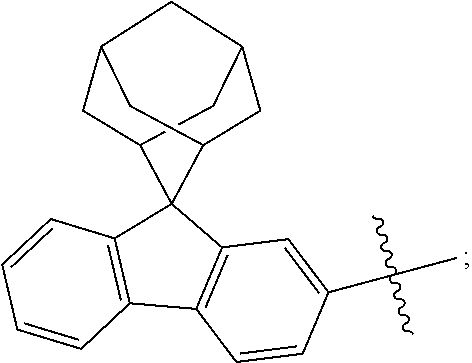
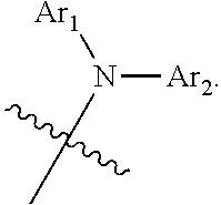
1. A nitrogen-containing compound, having a structure represented by Chemical Formula 1: ##STR00232## wherein L is selected from a single bond, or a substituted or an unsubstituted C6 to C12 arylene group; wherein Ar.sub.1 and Ar.sub.2 are each independently selected from a substituted or an unsubstituted C6 to C20 aryl group or from a substituted or an unsubstituted C12 to C20 heteroaryl group; the substituents of Ar.sub.1, Ar.sub.2 and L are each independently selected from an aryl group, a heteroaryl group, or a methyl group; the substituted C6 to C12 arylene group means that the total number of carbon atoms of the arylene group and the substituents thereon combined are from 6 to 12; the substituted C6 to C20 aryl group means that the total number of carbon atoms of the aryl group and the substituents thereon combined are from 6 to 20; the substituted C12 to C20 heteroaryl group means that the total number of carbon atoms of the heteroaryl group and the substituents thereon combined are from 12 to 20.
2. The nitrogen-containing compound according to claim 1, wherein L is selected from a single bond, a substituted or an unsubstituted phenylene group, a substituted or an unsubstituted naphthylene group, or a substituted or an unsubstituted biphenylene group.
3. The nitrogen-containing compound according to claim 1, wherein the nitrogen-containing compound has a relative molecular mass of not greater than 750.
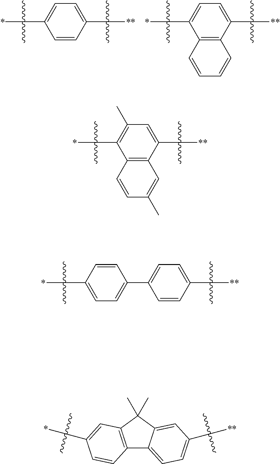
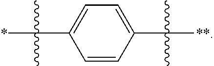
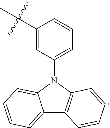
4. The nitrogen-containing compound according to claim 1, wherein L is selected from a single bond or the following substituents: ##STR00233## wherein, ##STR00234## represents a chemical bond; * represents a binding site where the above substituent is connected to ##STR00235## ** represents a binding site where the above substituent is connected to ##STR00236##
5. The nitrogen-containing compound according to claim 1, wherein at least one of Ar.sub.1 And Ar.sub.2 is selected from a substituted aryl group having 6 to 12 ring-forming carbon atoms, and the substituent on the substituted aryl group having 6 to 12 ring-forming carbon atoms is selected from an aryl group of 6 to 14 carbon atoms or a heteroaryl group of 6 to 12 carbon atoms.
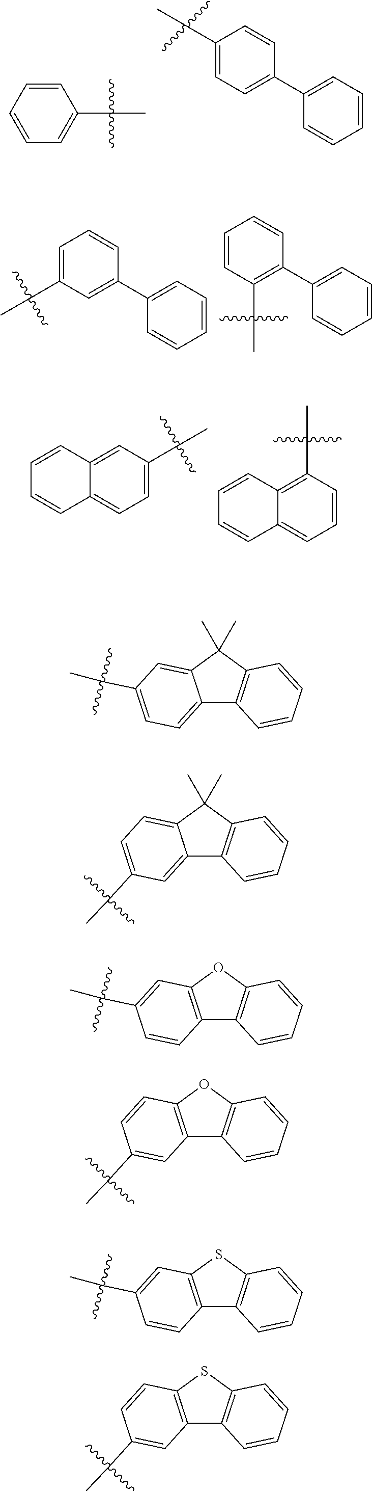
6. The nitrogen-containing compound according to claim 1, wherein Ar.sub.1 and Ar.sub.2 are each independently selected from the following substituents: ##STR00237## ##STR00238## ##STR00239## ##STR00240## ##STR00241## ##STR00242##
7. The nitrogen-containing compound according to claim 1, wherein the nitrogen-containing compound is selected from the following compounds: ##STR00243## ##STR00244## ##STR00245## ##STR00246## ##STR00247## ##STR00248## ##STR00249## ##STR00250## ##STR00251## ##STR00252## ##STR00253## ##STR00254## ##STR00255## ##STR00256## ##STR00257## ##STR00258## ##STR00259## ##STR00260## ##STR00261## ##STR00262## ##STR00263## ##STR00264## ##STR00265## ##STR00266## ##STR00267## ##STR00268## ##STR00269## ##STR00270## ##STR00271## ##STR00272## ##STR00273## ##STR00274## ##STR00275## ##STR00276## ##STR00277## ##STR00278## ##STR00279## ##STR00280## ##STR00281## ##STR00282## ##STR00283## ##STR00284## ##STR00285## ##STR00286## ##STR00287## ##STR00288## ##STR00289## ##STR00290## ##STR00291## ##STR00292## ##STR00293## ##STR00294## ##STR00295## ##STR00296## ##STR00297## ##STR00298## ##STR00299## ##STR00300## ##STR00301## ##STR00302## ##STR00303## ##STR00304## ##STR00305## ##STR00306## ##STR00307## ##STR00308## ##STR00309## ##STR00310## ##STR00311## ##STR00312## ##STR00313## ##STR00314## ##STR00315## ##STR00316## ##STR00317## ##STR00318## ##STR00319## ##STR00320## ##STR00321## ##STR00322## ##STR00323## ##STR00324## ##STR00325## ##STR00326## ##STR00327## ##STR00328## ##STR00329## ##STR00330## ##STR00331## ##STR00332## ##STR00333## ##STR00334## ##STR00335## ##STR00336## ##STR00337## ##STR00338## ##STR00339## ##STR00340## ##STR00341## ##STR00342## ##STR00343## ##STR00344## ##STR00345## ##STR00346## ##STR00347## ##STR00348## ##STR00349## ##STR00350## ##STR00351## ##STR00352## ##STR00353## ##STR00354## ##STR00355## ##STR00356## ##STR00357## ##STR00358## ##STR00359## ##STR00360## ##STR00361## ##STR00362## ##STR00363## ##STR00364## ##STR00365## ##STR00366## ##STR00367## ##STR00368## ##STR00369##
8. An organic electroluminescent device, comprising an anode and a cathode disposed opposite to each other, and a functional layer disposed between the anode and the cathode, wherein the functional layer comprises the nitrogen-containing compound according to claim 1.
9. The organic electroluminescent device according to claim 8, wherein the functional layer comprises a hole transport layer, and the hole transport layer comprises the nitrogen-containing compound.
10. The organic electroluminescent device according to claim 9, wherein the hole transport layer comprises a first hole transport layer and a second hole transport layer, and the first hole transport layer is disposed on the surface of the second hole transport layer close to the anode; the first hole transport layer or the second hole transport layer comprises the nitrogen-containing compound.
11. The organic electroluminescent device according to claim 8, wherein the functional layer comprises a hole injection layer, and the hole injection comprises the nitrogen-containing compound provided.
12. A photoelectric conversion device, comprising an anode and a cathode disposed opposite to each other, and a functional layer disposed between the anode and the cathode, wherein the functional layer comprises the nitrogen-containing compound according to claim 1.
13. The photoelectric conversion device according to claim 12, wherein the functional layer comprises a hole transport layer, and the hole transport layer comprises the nitrogen-containing compound.
14. The photoelectric conversion device according to claim 12, wherein the photoelectric conversion device is a solar cell.
Description
CROSS-REFERENCE TO RELATED APPLICATIONS
The present disclosure claims the priorities of Chinese Patent Application No. 201910515733.1 filed on Jun. 14, 2019, Chinese Patent Application No. 201910755507.0 filed on Aug. 15, 2019 and Chinese Patent Application No. 201910765403.8 filed on Aug. 19, 2019, the entireties of which are herein incorporated by reference.
TECHNICAL FIELD
The present disclosure relates to the technical field of electronic components, and in particular relates to a nitrogen-containing compound, an organic electroluminescent device using the nitrogen-containing compound, and a photoelectric conversion device using the nitrogen-containing compound.
BACKGROUND
With the development of electronic technology and the progress of material science, the application range of electronic components for realizing electroluminescence or photoelectric conversion becomes more and more extensive. Such electronic components generally include a cathode and an anode disposed opposite to each other, and a functional layer disposed between the cathode and the anode. The functional layer is composed of multiple organic or inorganic film layers and generally includes an energy conversion layer, a hole transport layer between the energy conversion layer and the anode, and an electron transport layer between the energy conversion layer and the cathode.
Taking an organic electroluminescent device as an example, the organic electroluminescent device generally includes an anode, a hole transport layer, an electroluminescent layer as an energy conversion layer, an electron transport layer and a cathode, which are sequentially stacked. When voltage is applied to the anode and the cathode, an electric field is generated between the two electrodes, electrons on the cathode side move to the electroluminescent layer and holes on the anode side also move to the luminescent layer under the action of the electric field, the electrons and the holes are combined in the electroluminescent layer to form excitons, and the excitons are in an excited state and release energy outwards, so that the electroluminescent layer emits light outwards.
In the prior art, KR1020190035567A, CN107459466A, CN106008424A, CN104583176A, CN103108859A and the like disclose materials that can be used to prepare hole transport layers in organic electroluminescent devices. However, there is still a need to develop new materials to further improve the performance of electronic components.
SUMMARY
The purpose of the present disclosure is to provide a nitrogen-containing compound, an organic electroluminescent device using the nitrogen-containing compound, and a photoelectric conversion device using the nitrogen-containing compound, the nitrogen-containing compound is used to improve the performance of the organic electroluminescent device and the photoelectric conversion device.
In order to achieve the purpose, the technical solutions adopted by the present disclosure are as follows:
According to a first aspect of the present disclosure, there is provided a nitrogen-containing compound having a structure represented by Chemical Formula 1:
##STR00002## wherein L is selected from a single bond, a substituted or unsubstituted C6 to C30 arylene group, and a substituted or unsubstituted C1 to C30 heteroarylene group;
Ar.sub.1 and Ar.sub.2 are each independently selected from a substituted or unsubstituted C1 to C35 alkyl group, a substituted or unsubstituted C2 to C35 alkenyl group, a substituted or unsubstituted C2 to C35 alkynyl group, a substituted or unsubstituted C3 to C35 cycloalkyl group, a substituted or unsubstituted C2 to C35 heterocycloalkyl group, a substituted or unsubstituted C7 to C30 aralkyl group, a substituted or unsubstituted C2 to C30 heteroaralkyl group, a substituted or unsubstituted C6 to C30 aryl group, and a substituted or unsubstituted C1 to C30 heteroaryl group;
the substituents of Ar.sub.1, Ar.sub.2 and L are each independently selected from deuterium, a cyano group, a nitro group, a halogen, a hydroxyl group, a substituted or unsubstituted C1 to C40 alkyl group, a substituted or unsubstituted C3 to C40 cycloalkyl group, a substituted or unsubstituted C2 to C40 alkenyl group, a substituted or unsubstituted C2 to C40 alkynyl group, a substituted or unsubstituted C2 to C40 heterocycloalkyl group, a substituted or unsubstituted C7 to C40 aralkyl group, a substituted or unsubstituted C2 to C40 heteroaralkyl group, a substituted or unsubstituted C6 to C40 aryl group, a substituted or unsubstituted C1 to C40 heteroaryl group, a substituted or unsubstituted C1 to C40 alkoxy group, a substituted or unsubstituted C1 to C40 alkylamino group, a substituted or unsubstituted C6 to C40 arylamino group, a substituted or unsubstituted C1 to C40 alkylthio group, a substituted or unsubstituted C7 to C40 aralkylamino group, a substituted or unsubstituted C1 to C24 heteroarylamino group, a substituted or unsubstituted C1 to C45 alkylsilyl group, a substituted or unsubstituted C6 to C50 arylsilyl group, a substituted or unsubstituted C6 to C30 aryloxy group, and a substituted or unsubstituted C6 to C30 arylthio group.
In the present disclosure, Ar.sub.1 is not 9,9-diphenylfluorene, and Ar.sub.2 is not 9,9-diphenylfluorene.
According to a second aspect of the present disclosure, there is provided an organic electroluminescent device including an anode and a cathode disposed opposite to each other, and a functional layer disposed between the anode and the cathode, and the functional layer includes the above nitrogen-containing compound.
According to a third aspect of the present disclosure, there is provided a photoelectric conversion device including an anode and a cathode disposed opposite to each other, and a functional layer disposed between the anode and the cathode, and the functional layer includes the above nitrogen-containing compound.
In the nitrogen-containing compound, the organic electroluminescent device using the nitrogen-containing compound and the photoelectric conversion device using the nitrogen-containing compound, the nitrogen-containing compound has good hole transport characteristics, and can be applied between the anode and the energy conversion layer of the organic electroluminescent device and the photoelectric conversion device to improve the hole transport efficiency between the anode and the energy conversion layer, so as to improve the luminous efficiency of the organic electroluminescent device and the power generation efficiency of the photoelectric conversion device. Because the nitrogen-containing compound also has higher electron tolerance and film-forming property, it can improve the efficiency and the service life of an organic electroluminescent device and a photoelectric conversion device. Moreover, the nitrogen-containing compound has better thermal stability, can keep stable structure at high temperature for a long time, not only ensures the uniform and stable performance of an organic electroluminescent device and a photoelectric conversion device prepared at different stages, but also ensures that the performance of an organic electroluminescent device and a photoelectric conversion device prepared at the later stage of mass production is not reduced.
BRIEF DESCRIPTION OF THE DRAWINGS
The above and other features and advantages of the present disclosure will become more apparent from the detailed description of the exemplary embodiments with reference to the following figures.
FIG. 1 is a schematic structural view of an organic electroluminescent device according to an embodiment of the present disclosure.
FIG. 2 is a schematic structural view of a photoelectric conversion device according to an embodiment of the present disclosure.
Reference numerals are illustrated as follows: 100, Anode; 200, Cathode; 300, Functional layer; 310, Hole injection layer; 320, Hole transport layer; 321, First hole transport layer; 322, Second hole transport layer; 330, Organic electroluminescent layer; 340, Hole blocking layer; 350, Electron transport layer; 360, Electron injection layer; 370, Photoelectric conversion layer.
DETAILED DESCRIPTION
Exemplary embodiments will now be described more fully with reference to the figures. Exemplary embodiments may, however, be embodied in many different forms and should not be construed as limited to the examples set forth herein; rather, these embodiments are provided so that this disclosure will be full and complete, and will fully convey the concept of exemplary embodiments to those skilled in the art. The described features, structures, or characteristics may be combined in any suitable manner in one or more embodiments. In the following description, numerous specific details are provided to give a full understanding of embodiments of the present disclosure.
In the figures, the thickness of regions and layers may be exaggerated for clarity. The same reference numerals denote the same or similar structures in the figures, and thus detailed descriptions thereof will be omitted.
The described features, structures, or characteristics may be combined in any suitable manner in one or more embodiments. In the following description, numerous specific details are provided to give a full understanding of embodiments of the present disclosure. Those skilled in the art will recognize, however, that the embodiments of the present disclosure can be practiced without one or more of the specific details, or with other methods, components, materials, and so forth. In other instances, well-known structures, materials, or operations are not shown or described in detail to avoid obscuring the primary technical ideas of the present disclosure.
The present disclosure provides a nitrogen-containing compound having a structure represented by Chemical Formula 1:
##STR00003##
wherein L is selected from a single bond, a substituted or unsubstituted C6 to C30 arylene group, and a substituted or unsubstituted C1 to C30 heteroarylene group;
Ar.sub.1 and Ar.sub.2 are each independently selected from a substituted or unsubstituted C1 to C35 alkyl group, a substituted or unsubstituted C2 to C35 alkenyl group, a substituted or unsubstituted C2 to C35 alkynyl group, a substituted or unsubstituted C3 to C35 cycloalkyl group, a substituted or unsubstituted C2 to C35 heterocycloalkyl group, a substituted or unsubstituted C7 to C30 aralkyl group, a substituted or unsubstituted C2 to C30 heteroaralkyl group, a substituted or unsubstituted C6 to C30 aryl group, and a substituted or unsubstituted C1 to C30 heteroaryl group;
the substituents of Ar.sub.1, Ar.sub.2 and L are each independently selected from deuterium, a cyano group, a nitro group, a halogen, a hydroxyl group, a substituted or unsubstituted C1 to C40 alkyl group, a substituted or unsubstituted C3 to C40 cycloalkyl group, a substituted or unsubstituted C2 to C40 alkenyl group, a substituted or unsubstituted C2 to C40 alkynyl group, a substituted or unsubstituted C2 to C40 heterocycloalkyl group, a substituted or unsubstituted C7 to C40 aralkyl group, a substituted or unsubstituted C2 to C40 heteroaralkyl group, a substituted or unsubstituted C6 to C40 aryl group, a substituted or unsubstituted C1 to C40 heteroaryl group, a substituted or unsubstituted C1 to C40 alkoxy group, a substituted or unsubstituted C1 to C40 alkylamino group, a substituted or unsubstituted C6 to C40 arylamino group, a substituted or unsubstituted C1 to C40 alkylthio group, a substituted or unsubstituted C7 to C40 aralkylamino group, a substituted or unsubstituted C1 to C24 heteroarylamino group, a substituted or unsubstituted C1 to C45 alkylsilyl group, a substituted or unsubstituted C6 to C50 arylsilyl group, a substituted or unsubstituted C6 to C30 aryloxy group, and a substituted or unsubstituted C6 to C30 arylthio group.
In the present disclosure, Ar.sub.1 is not 9,9-diphenylfluorene, and Ar.sub.2 is not 9,9-diphenylfluorene.
In the present disclosure, the number of carbon atoms of L, Ar.sub.1 and Ar.sub.2 means all the number of carbon atoms thereon. For Example, if L is a substituted arylene group of 12 carbon atoms, all of the carbon atoms of the arylene group and the substituents thereon are 12.
Alternatively, the unsubstituted C1 to C35 alkyl means a straight chain alkyl having 1 to 35 carbon atoms or a branched alkyl having 1 to 13 carbon atoms, such as methyl, ethyl, propyl, isobutyl, sec-butyl, pentyl, isopentyl, hexyl, tert-butyl and the like. The substituted C1 to C35 alkyl group means that at least one hydrogen atom is substituted with deuterium atom, F, Cl, I, CN, a hydroxyl group, a nitro group, an amino group, etc. In some embodiments, the alkyl is a C1 to C4 alkyl, such as methyl, ethyl, propyl, isobutyl, or tert-butyl.
Alternatively, the unsubstituted C2 to C35 alkenyl means an alkenyl having 2 to 35 carbon atoms, including a C2 to C35 straight-chain alkenyl having a carbon-carbon double bond, or a C1 to C13 branched-chain alkenyl, such as vinyl, propenyl, allyl, isopropenyl, 2-butenyl, etc. The substituted C2 to C35 alkenyl group means that at least one hydrogen atom is substituted with deuterium atom, F, Cl, I, CN, a hydroxyl group, a nitro group, an amino group, etc.
Alternatively, the unsubstituted C2 to C35 alkynyl means an alkynyl having 2 to 35 carbon atoms, including a C2 to C35 straight chain alkynyl having a triple carbon-carbon bond, or a C1 to C10 branched alkynyl having a triple carbon-carbon bond, such as ethynyl, 2-propynyl, etc. The substituted C2 to C35 alkynyl group means that at least one hydrogen atom is substituted with deuterium atom, F, Cl, I, CN, a hydroxyl group, a nitro group, an amino group, etc.
The nitrogen-containing compound disclosed by the present disclosure has good hole transport efficiency, and therefore can be applied as a hole transport material in organic electroluminescent devices and photoelectric conversion devices. For example, the nitrogen-containing compound of the present disclosure may be applied between an anode and an organic electroluminescent layer of an organic electroluminescent device so as to transport holes on the anode to the organic electroluminescent layer. Alternatively, the nitrogen-containing compound of the present disclosure may be applied to any one or more layers of a hole injection layer, a hole transport layer, and an electron blocking layer of an organic electroluminescent device. For another example, the nitrogen-containing compounds of the present disclosure may be applied between an anode and a photoelectric conversion layer of a photoelectric conversion device in order to transport holes on the photoelectric conversion layer to the anode.
In one embodiment of the present disclosure, the substituents of Ar.sub.1, Ar.sub.2, and L are each independently selected from deuterium, a cyano group, a nitro group, a halogen, a hydroxyl group, a substituted or unsubstituted C1 to C33 alkyl group, a substituted or unsubstituted C3 to C33 cycloalkyl group, a substituted or unsubstituted C2 to C33 alkenyl group, a substituted or unsubstituted C2 to C33 alkynyl group, a substituted or unsubstituted C2 to C33 heterocycloalkyl group, a substituted or unsubstituted C7 to C33 aralkyl group, a substituted or unsubstituted C2 to C33 heteroaralkyl group, a substituted or unsubstituted C6 to C33 aryl group, a substituted or unsubstituted C1 to C33 heteroaryl group, a substituted or unsubstituted C1 to C33 alkoxy group, a substituted or unsubstituted C1 to C33 alkylamino group, a substituted or unsubstituted C6 to C33 arylamino group, a substituted or unsubstituted C1 to C33 alkylthio group, a substituted or unsubstituted C7 to C33 aralkylamino group, a substituted or unsubstituted C1 to C33 heteroarylamino group, a substituted or unsubstituted C1 to C33 alkylsilyl group, a substituted or unsubstituted C6 to C33 arylsilyl group, a substituted or unsubstituted C6 to C33 aryloxy group, and a substituted or unsubstituted C6 to C33 arylthio group.
In one embodiment of the present disclosure, L is selected from a single bond, a substituted or unsubstituted phenylene group, a substituted or unsubstituted naphthylene group, a substituted or unsubstituted biphenylene group, a substituted or unsubstituted terphenylene group, and a substituted or unsubstituted fluorenylene group.
In one embodiment of the present disclosure, the nitrogen-containing compound has a relative molecular mass of not greater than 750, so as to ensure that the nitrogen-containing compound of the present disclosure has good thermal stability and to ensure that the nitrogen-containing compound of the present disclosure maintains stable structure during long-term evaporation.
In one embodiment of the present disclosure, L is selected from a single bond, a substituted or unsubstituted C6 to C12 arylene group. Alternatively, L is selected from a single bond or an unsubstituted C6 to C12 arylene group, so that the preparation difficulty and the preparation cost of the nitrogen-containing compound disclosed herein can be reduced, the cost performance of the nitrogen-containing compound disclosed herein when applied to electronic components on a large scale is improved, the cost of the electronic components is further reduced, and particularly, the cost of organic electroluminescent devices and photoelectric conversion devices is reduced.
In one embodiment of the present disclosure, L is selected from a single bond or the following substituents:
##STR00004##
wherein,
##STR00005## represents a chemical bond;
* represents a binding site where the above substituent is connected to
##STR00006##
** represents a binding site where the above substituent is connected to
##STR00007##
For Example, in the compound
##STR00008## L is
##STR00009##
In one embodiment of the present disclosure, Ar.sub.1 and Ar.sub.2 are each independently selected from a substituted or unsubstituted C6 to C20 aryl group and a substituted or unsubstituted C12 to C20 heteroaryl group.
In one embodiment of the present disclosure, Ar.sub.1 and Ar.sub.2 are each independently selected from a substituted or unsubstituted C6 to C25 aryl group, and Ar.sub.1 is not 9,9-diphenylfluorene and Ar.sub.2 is not 9,9-diphenylfluorene.
In one embodiment of the present disclosure, at least one of Ar.sub.1 and Ar.sub.2 is selected from a substituted aryl group having 6 to 12 ring-forming carbon atoms, and the substituent on the substituted aryl group having 6 to 12 ring-forming carbon atoms is selected from an C6 to C14 aryl group and a C6 to C12 heteroaryl group. For Example, Ar.sub.1 is
##STR00010## then Ar.sub.1 is a substituted aryl group having 6 ring-forming carbon atoms, and the substituent of the substituted aryl group having 6 ring-forming carbon atoms is a C12 heteroaryl group.
In one embodiment of the present disclosure, Ar.sub.1 and Ar.sub.2 are each independently selected from the following substituents:
##STR00011## ##STR00012## ##STR00013## ##STR00014## ##STR00015## ##STR00016##
In one embodiment of the present disclosure, Ar.sub.1 and Ar.sub.2 are each independently selected from the following substituent:
##STR00017##
In one embodiment of the present disclosure, Ar.sub.1 and Ar.sub.2 are each independently selected from the following substituents:
##STR00018##
In one embodiment of the present disclosure, the nitrogen-containing compound is selected from the following compounds:
##STR00019## ##STR00020## ##STR00021## ##STR00022## ##STR00023## ##STR00024## ##STR00025## ##STR00026## ##STR00027## ##STR00028## ##STR00029## ##STR00030## ##STR00031## ##STR00032## ##STR00033## ##STR00034## ##STR00035## ##STR00036## ##STR00037## ##STR00038## ##STR00039## ##STR00040## ##STR00041## ##STR00042## ##STR00043## ##STR00044## ##STR00045## ##STR00046## ##STR00047## ##STR00048## ##STR00049## ##STR00050## ##STR00051## ##STR00052## ##STR00053## ##STR00054## ##STR00055## ##STR00056## ##STR00057## ##STR00058## ##STR00059## ##STR00060## ##STR00061## ##STR00062## ##STR00063## ##STR00064## ##STR00065## ##STR00066## ##STR00067## ##STR00068## ##STR00069## ##STR00070## ##STR00071## ##STR00072## ##STR00073## ##STR00074## ##STR00075## ##STR00076## ##STR00077## ##STR00078## ##STR00079## ##STR00080## ##STR00081## ##STR00082## ##STR00083## ##STR00084## ##STR00085## ##STR00086## ##STR00087## ##STR00088## ##STR00089## ##STR00090## ##STR00091## ##STR00092## ##STR00093## ##STR00094## ##STR00095## ##STR00096## ##STR00097## ##STR00098## ##STR00099##
##STR00100## ##STR00101## ##STR00102## ##STR00103## ##STR00104## ##STR00105## ##STR00106## ##STR00107## ##STR00108## ##STR00109## ##STR00110## ##STR00111## ##STR00112## ##STR00113## ##STR00114## ##STR00115## ##STR00116## ##STR00117## ##STR00118## ##STR00119## ##STR00120## ##STR00121## ##STR00122## ##STR00123## ##STR00124## ##STR00125## ##STR00126## ##STR00127## ##STR00128## ##STR00129## ##STR00130## ##STR00131##
The nitrogen-containing compound of the present disclosure introduces an adamantane-2-yl structure at the 9-position of fluorene, the adamantyl can improve the electron density of a conjugated system of a fluorene ring and the whole nitrogen-containing compound through a hyperconjugation effect, so that the hole conduction efficiency of the nitrogen-containing compound is improved, and further the carrier conduction efficiency and the service life of an organic electroluminescent device and a photoelectric conversion device are improved. The adamantane-2-yl group is introduced at the 9-position of fluorene rather than at the end, and into the side chains of the amines of the nitrogen-containing compounds of the present disclosure rather than at the end. Due to the large steric hindrance effect of the adamantane-2-yl, the angle and the conjugation degree between each branched chain of amine can be adjusted, and further the HOMO value of the nitrogen-containing compound can be adjusted, so that the HOMO value of the nitrogen-containing compound can be more matched with an adjacent film layer, the driving voltage of an organic electroluminescent device can be further reduced, or the open-circuit voltage of a photoelectric conversion device can be improved.
Moreover, in the nitrogen-containing compound of the present disclosure, compared with the modification of the fluorene group with an aryl group, the modification of the fluorene group with an alkyl structure having a large volume can avoid the excessive .pi.-.pi. stacking effect, and can reduces the symmetry of the nitrogen-containing compounds of the present disclosure, which in turn can improve the film-forming properties of the nitrogen-containing compounds. Moreover, the adamantane-2-yl group can ensure that the nitrogen-containing compound of the present disclosure has an appropriate molecular weight, further ensure that the nitrogen-containing compound of the present disclosure has an appropriate glass transition temperature, and improve the physical and thermal stability during the preparation of an organic electroluminescent device and a photoelectric conversion device.
The present disclosure also provides an organic electroluminescent device. As shown in FIG. 1, the organic electroluminescent device includes an anode 100 and a cathode 200 disposed opposite to each other, and a functional layer 300 disposed between the anode 100 and the cathode 200. The functional layer 300 includes the nitrogen-containing compound provided by the present disclosure.
In one embodiment of the present disclosure, the nitrogen-containing compound provided by the present disclosure may be used to form at least one organic film layer in the functional layer 300, so as to improve the performance of the organic electroluminescent device, in particular, to improve the service life of the organic electroluminescent device, to improve the luminous efficiency of the organic electroluminescent device, to reduce the driving voltage of the organic electroluminescent device, or to improve the uniformity and stability of the organic electroluminescent device in mass production.
In one embodiment of the present disclosure, the functional layer 300 includes a hole transport layer 320, and the hole transport layer 320 includes the nitrogen-containing compound provided by the present disclosure. The hole transport layer 320 may be composed of the nitrogen-containing compound provided by the present disclosure, and also may be composed of the nitrogen-containing compound provided by the present disclosure and other materials.
Alternatively, the hole transport layer 320 includes a first hole transport layer 321 and a second hole transport layer 322, and the first hole transport layer 321 is disposed on the surface of the second hole transport layer 322 close to the anode 100. The first hole transport layer 321 or the second hole transport layer 322 includes the nitrogen-containing compound provided by the present disclosure. That is, one of the first hole transporting layer 321 and the second hole transporting layer 322 may contain the nitrogen-containing compound provided by the present disclosure, or both the first hole transporting layer 321 and the second hole transporting layer 322 may contain the nitrogen-containing compound provided by the present disclosure. It is to be understood that the first hole transport layer 321 or the second hole transport layer 322 may or may not contain other materials.
Further alternatively, the first hole transport layer 321 or the second hole transport layer 322 is composed of the nitrogen-containing compound provided by the present disclosure.
In one embodiment of the present disclosure, the functional layer 300 includes a hole injection layer 310, and the hole injection layer 310 may include the nitrogen-containing compound provided by the present disclosure. The hole injection layer 310 may be composed of the nitrogen-containing compound provided by the present disclosure, or may be composed of the nitrogen-containing compound provided by the present disclosure and other materials.
Alternatively, the hole injection layer 310 is composed of the nitrogen-containing compound provided by the present disclosure.
In one embodiment of the present disclosure, the anode 100 includes an anode material, which is preferably a material having a large work function that facilitates hole injection into the functional layer. Specific Examples of the anode material include: metals such as nickel, platinum, vanadium, chromium, copper, zinc and gold or alloys thereof; metal oxides such as zinc oxide, indium oxide, indium tin oxide (ITO), and indium zinc oxide (IZO); combinations of metals and oxides, such as ZnO:Al or SnO.sub.2:Sb; or conductive polymers such as poly(3-methylthiophene), poly[3,4-(ethylene-1,2-dioxy)thiophene](PEDT), polypyrrole, and polyaniline, but not limited thereto. Preferably, a transparent electrode including indium tin oxide (ITO) is included as an anode.
In one embodiment of the present disclosure, the cathode 200 includes a cathode material that is a material having a small work function that facilitates electron injection into the functional layer. Specific Examples of the cathode material include: metals such as magnesium, calcium, sodium, potassium, titanium, indium, yttrium, lithium, gadolinium, aluminum, silver, tin, and lead or alloys thereof; or multilayer materials such as LiF/Al, Liq/Al, LiO.sub.2/Al, LiF/Ca, LiF/Al and BaF.sub.2/Ca, but not limited thereto. Preferably, a metal electrode including aluminum is included as a cathode.
In one embodiment of the present disclosure, as shown in FIG. 1, the organic electroluminescent device may include an anode 100, a hole injection layer 310, a hole transport layer 320, an organic electroluminescent layer 330, a hole blocking layer 340, an electron transport layer 350, an electron injection layer 360, and a cathode 200, which are sequentially stacked. Wherein at least one of the hole injection layer 310 and the hole transport layer 320 includes the nitrogen-containing compound of the present disclosure.
The present disclosure also provides a photoelectric conversion device, which may include an anode 100 and a cathode 200 disposed opposite to each other, and a functional layer 300 disposed between the anode 100 and the cathode 200, as shown in FIG. 2. The functional layer 300 includes the nitrogen-containing compound provided by the present disclosure.
In one embodiment of the present disclosure, the nitrogen-containing compound provided by the present disclosure may be used to form at least one organic thin layer in the functional layer 300 to improve the performance of the photoelectric conversion device, in particular, to improve the service life of the photoelectric conversion device, to improve the open circuit voltage of the photoelectric conversion device, or to improve the uniformity and stability of the photoelectric conversion device in mass production.
In one embodiment of the present disclosure, the functional layer 300 includes a hole transport layer 320, and the hole transport layer 320 includes the nitrogen-containing compound of the present disclosure. The hole transport layer 320 may be composed of the nitrogen-containing compound provided by the present disclosure, or may be composed of the nitrogen-containing compound provided by the present disclosure and other materials.
Alternatively, the hole transport layer 320 may further include an inorganic doping material to improve the hole transport property of the hole transport layer 320.
In one embodiment of the present disclosure, as shown in FIG. 2, the photoelectric conversion device may include an anode 100, a hole transport layer 320, a photoelectric conversion layer 370, an electron transport layer 350, and a cathode 200, which are sequentially stacked.
Alternatively, the photoelectric conversion device may be a solar cell, and particularly may be an organic thin film solar cell.
Synthesis of Compounds
Synthesis of Compounds 1 to 23 by the Following Synthetic Route
##STR00132##
Synthesis of Compound 1
##STR00133##
Magnesium strips (13.54 g, 564 mmol) and diethyl ether (100 mL) were placed in a dry round bottom flask under the protection of nitrogen, and iodine (100 mg) was added. Then, the solution of 2'-bromo-4-chlorobiphenyl (50.00 g, 187.0 mmol) dissolved in diethyl ether (200 mL) was slowly dripped into the flask, the temperature was raised to 35.degree. C. after dropping, and the stirring was carried out for 3 hours. The reaction solution was cooled to 0.degree. C., the solution of adamantanone (22.45 g, 149 mmol) dissolved in diethyl ether (200 mL) was slowly dropped, the temperature was raised to 35.degree. C. after dropping, and stirring was carried out for 6 hours. The reaction solution was cooled to room temperature, 5% hydrochloric acid was added into the reaction solution until the pH value was less than 7, and the stirring was carried out for 1 hour. Diethyl ether (200 mL) was added into the reaction solution for extraction, the combined organic phases were dried by using anhydrous magnesium sulfate, the mixture was filtered, and the solvent was removed under reduced pressure. The crude product was purified by silica column chromatography using ethyl acetate/n-heptane (1:2) as mobile phase to obtain Intermediate I-A-1 (43 g, 68% yield) as a white solid.
##STR00134##
Intermediate I-A-1 (43 g, 126.9 mmol), trifluoroacetic acid (36.93 g, 380.6 mmol) and dichloromethane (300 mL) were added into a round-bottom flask, and the stirring was carried out under the protection of nitrogen for 2 hours. Then, an aqueous solution of sodium hydroxide was added into the reaction solution until the pH value to 8, followed by liquid separation, the organic phase was dried with anhydrous magnesium sulfate, the mixture was filtered, and the solvent was removed under reduced pressure. The crude product was purified by silica column chromatography using dichloromethane/n-heptane (1:2) to obtain Intermediate I-A (39.2 g, 96.3% yield) as a white solid.
##STR00135##
4-bromobiphenyl (5.0 g, 21.0 mmol), 4-aminobiphenyl (3.63 g, 21.45 mmol), tris (dibenzylideneacetone) dipalladium (0.20 g, 0.21 mmol), 2-dicyclohexylphosphino-2',4',6'-triisopropylbiphenyl (0.20 g, 0.42 mmol) and sodium tert-butoxide (3.09 g, 32.18 mmol) were added into toluene (80 mL), the reaction solution was heated to 108.degree. C. under the protection of nitrogen and stirred for 2 h. Then, the reaction solution was cooled to room temperature, the reaction solution was washed with water, magnesium sulfate was added for drying, the mixture was filtered, and the solvent was removed under reduced pressure. The crude product was purified by recrystallization using a dichloromethane/ethyl acetate system to obtain Intermediate II-A (5.61 g, 81.5% yield) as a pale-yellow solid.
##STR00136##
Intermediate I-A (5.6 g, 17.46 mmol), Intermediate II-A (5.61 g, 17.46 mmol), tris(dibenzylideneacetone)dipalladium (0.16 g, 0.17 mmol), 2-dicyclohexylphosphino-2',6'-dimethoxybiphenyl (0.14 g, 0.35 mmol) and sodium tert-butoxide (2.52 g, 26.18 mmol) were added into toluene (40 mL), the reaction solution was heated to 108.degree. C. under the protection of nitrogen, and stirred for 3 h. Then, the reaction solution was cooled to room temperature, the reaction solution was washed with water, magnesium sulfate was added for drying, the mixture was filtered, and the solvent was removed from the filtrate under reduced pressure. The crude product was purified by recrystallization using a toluene system to obtain Compound 1 (4.35 g, 41% yield) as a white solid. Mass spectrum: m/z=606.3 (M+H).sup.+. .sup.1H NMR (400 MHz, CD.sub.2Cl.sub.2): 8.09 (d, 1H), 7.91 (s, 1H), 7.74-7.71 (m, 2H), 7.61 (d, 4H), 7.55 (d, 4H), 7.43 (t, 4H), 7.37-7.30 (m, 3H), 7.25-7.24 (m, 5H), 7.18 (dd, 1H), 2.91 (d, 2H), 2.61 (d, 2H), 2.16 (s, 1H), 1.90 (s, 3H), 1.77 (d, 2H), 1.69 (d, 2H), 1.60 (s, 2H) ppm.
Referring to the Synthesis of Compound 1, Compounds 2 to 23 were prepared with Raw Material 2 instead of 4-bromobiphenyl and Raw Material 1 instead of 4-aminobiphenyl. Wherein, the Compound Number, Compound Structures, Raw Materials, Synthesis Yields, and Characterization Data of Compounds 2 to 23 are shown in Table 1.
TABLE-US-00001 TABLE 1 Compound Structure, Preparation and Characterization Data Com- Mass pound (m/z) num- Raw Material Raw Material Yield (M + ber 1 2 Compound Structure (%) H).sup.+ 2 ##STR00137## ##STR00138## ##STR00139## 67 646.3 3 ##STR00140## ##STR00141## 69 620.3 4 ##STR00142## ##STR00143## 72 620.3 5 ##STR00144## ##STR00145## 67 695.3 6 ##STR00146## ##STR00147## 54 696.3 7 ##STR00148## ##STR00149## ##STR00150## 55 646.3 8 ##STR00151## ##STR00152## 59 695.3 9 ##STR00153## ##STR00154## ##STR00155## 61 686.4 10 ##STR00156## ##STR00157## 62 676.3 11 ##STR00158## ##STR00159## 47 646.3 12 ##STR00160## ##STR00161## 49 670.3 13 ##STR00162## ##STR00163## ##STR00164## 53 504.3 14 ##STR00165## ##STR00166## 55 619.3 15 ##STR00167## ##STR00168## 67 606.3 16 ##STR00169## ##STR00170## 69 630.3 17 ##STR00171## ##STR00172## ##STR00173## 70 554.3 18 ##STR00174## ##STR00175## 50 630.3 19 ##STR00176## ##STR00177## 43 630.3 20 ##STR00178## ##STR00179## ##STR00180## 49 669.3 21 ##STR00181## ##STR00182## 48 670.3 22 ##STR00183## ##STR00184## ##STR00185## 54 660.3 23 ##STR00186## ##STR00187## ##STR00188## 58 745.4
Compound 3 was identified by .sup.1H-NMR.
.sup.1H-NMR (400 MHz, CD.sub.2Cl.sub.2): 8.09 (d, 1H), 7.94 (s, 1H), 7.90 (d, 1H), 7.84 (d, 1H), 7.73 (t, 2H), 7.61 (d, 2H), 7.56 (d, 2H), 7.51 (d, 1H), 7.45-7.31 (m, 7H), 7.27-7.24 (m, 3H), 7.20 (dd, 2H), 2.91 (d, 2H), 2.60 (d, 2H), 2.15 (s, 1H), 1.88 (s, 3H), 1.76 (d, 2H), 1.67 (d, 2H), 1.60 (s, 2H) ppm.
Compound 7 was identified by .sup.1H-NMR.
.sup.1H-NMR (400 MHz, CD.sub.2Cl.sub.2): 8.03 (d, 2H), 7.64 (d, 1H), 7.58-7.57 (m, 2H), 7.51 (d, 1H), 7.47 (d, 1H), 7.42-7.39 (m, 2H), 7.36 (t, 2H), 7.33-7.26 (m, 3H), 7.22-7.18 (m, 4H), 7.06 (t, 2H), 7.01-6.99 (m, 2H), 6.89 (dd, 2H), 2.86 (d, 2H), 2.43 (d, 2H), 2.11 (s, 1H), 1.84 (s, 2H), 1.78 (s, 1H), 1.71 (d, 2H), 1.58 (d, 2H), 1.47 (s, 2H), 1.30 (s, 6H) ppm.
Synthesis of Compounds 24 to 30 by the Following Synthetic Route
##STR00189## ##STR00190##
Synthesis of Compound 24
##STR00191##
Intermediate I-A (20 g, 62.34 mmol), p-chlorobenzoic acid (9.75 g, 62.34 mmol), tetrakis(triphenylphosphine)palladium (0.72 g, 0.62 mmol), potassium carbonate (17.2 g, 124.6 mmol), tetrabutylammonium chloride (0.34 g, 1.25 mmol), toluene (160 mL), ethanol (40 mL) and deionized water (40 mL) were added into a round bottom flask, the reaction solution was heated to 78.degree. C. under the protection of nitrogen, and stirred for 8 hours. The reaction solution was cooled to room temperature, toluene (100 mL) was added for extraction, the combined organic phases were dried by using anhydrous magnesium sulfate, the mixture was filtered, and the solvent was removed under reduced pressure. The crude product was purified by silica column chromatography using n-heptane as mobile phase, followed by recrystallization using a dichloromethane/ethyl acetate system to obtain Intermediate I-A-2 (18.6 g, 75%) as a white solid.
##STR00192##
Bromobenzene (10.0 g, 38.0 mmol), 4-aminobiphenyl (7.07 g, 41.8 mmol), tris(dibenzylideneacetone)dipalladium (0.35 g, 0.38 mmol), 2-dicyclohexylphosphino-2',4',6'-triisopropylbiphenyl (0.36 g, 0.76 mmol) and sodium tert-butoxide (5.48 g, 57.0 mmol) were added into toluene (80 mL), the reaction solution heated to 108.degree. C. under the protection of nitrogen and stirred for 2 h. Then, the reaction solution was cooled to room temperature, magnesium sulfate was added for drying after washing with water, the mixture was filtered, and the solvent was removed from the filtrate under reduced pressure. The crude product was purified by recrystallization using a dichloromethane/ethyl acetate system to obtain Intermediate II-B (11.5 g, 86%) as a pale-yellow solid.
##STR00193##
Intermediate I-A-2 (3.50 g, 10.9 mmol), Intermediate II-B (3.51 g, 10.9 mmol), tris(dibenzylideneacetone)dipalladium (0.20 g, 0.22 mmol), 2-dicyclohexyl phosphorus-2',6'-dimethoxy biphenyl (0.18 g, 0.44 mmol) and sodium tert-butoxide (1.58 g, 16.4 mmol) were added into toluene (30 mL), the reaction solution was heated to 110.degree. C. under the protection of nitrogen, and stirred for 8 h. Then, the reaction solution was cooled to room temperature, magnesium sulfate was added for drying after washing with water, the mixture was filtered, and the solvent was removed from the filtrate under reduced pressure. The crude product was purified by recrystallization using a toluene system to obtain Compound 24 (4.35 g, 65.81%) as a white solid. Mass spectrum: m/z=606.3 (M+H).sup.+.
Referring to the synthesis of Compound 24, Compounds 25 to 30 were prepared with Raw Material 3 instead of 4-aminobiphenyl and Raw Material 4 instead of bromobenzene. Wherein, the Compound Number, Compound Structures, Raw Materials, Synthesis Yields, and Characterization Data of of Compounds 25 to 30 are shown in Table 2.
TABLE-US-00002 TABLE 2 Compound Structure, Preparation and Characterization Data Com- Mass pound (m/z) Num- Raw Yield (M + ber Material 3 Raw Material 4 Compound Structure (%) H).sup.+ 25 ##STR00194## ##STR00195## ##STR00196## 61 682.3 26 ##STR00197## ##STR00198## ##STR00199## 54 736.4 27 ##STR00200## ##STR00201## ##STR00202## 59 682.3 28 ##STR00203## ##STR00204## 63 656.3 29 ##STR00205## ##STR00206## ##STR00207## 66 680.3 30 ##STR00208## ##STR00209## ##STR00210## 41 745.4
Synthesis of Compound 31
##STR00211##
2-bromo-N-phenylcarbazole (10.0 g, 31.0 mmol), 2-aminobiphenyl (5.78 g, 34.1 mmol), tris(dibenzylideneacetone)dipalladium (0.28 g, 0.31 mmol), 2-dicyclohexylphosphino-2',4',6'-triisopropylbiphenyl (0.30 g, 0.62 mmol) and sodium tert-butoxide (4.47 g, 46.6 mmol) were added into toluene (80 mL), the reaction solution was heated to 108.degree. C. under the protection of nitrogen, and stirred for 4 h. Then, the reaction solution was cooled to room temperature, magnesium sulfate was added for drying after washing with water, the mixture was filtered, and the solvent was removed from the filtrate under reduced pressure. The crude product was purified by recrystallization using a dichloromethane/n-heptane system to obtain Intermediate II-C (8.65 g, 67.81% yield) as an orange solid.
##STR00212##
Intermediate I-A (3.5 g, 10.9 mmol), Intermediate II-C (4.48 g, 10.9 mmol), tris(dibenzylideneacetone)dipalladium (0.20 g, 0.22 mmol), 2-dicyclohexylphosphino-2',6'-dimethoxy biphenyl (0.18 g, 0.44 mmol) and the sodium tert-butoxide (1.57 g, 16.3 mmol) were added into toluene (30 mL), the reaction solution was heated to 108.degree. C. under the protection of nitrogen, and stirred for 10 h. The reaction solution was cooled to room temperature, magnesium sulfate was added for drying after washing with water, the mixture was filtered, the filtrate was purified with silica column chromatography using dichloromethane/n-heptane (1/5) as mobile phase, and the solvent was removed from the column solution under reduced pressure. The crude product was purified by recrystallization using a dichloroethane system to obtain Compound 31 (5.42 g, 71.5% yield) as a white solid. Mass spectrum: m/z=695.3 (M+H).sup.+.
Synthesis of Compound 32
##STR00213##
Intermediate I-A (3.5 g, 10.9 mmol), diphenylamine (1.85 g, 10.9 mmol), tris(dibenzylideneacetone)dipalladium (0.20 g, 0.22 mmol), 2-dicyclohexylphosphino-2',6'-dimethoxybiphenyl (0.18 g, 0.44 mmol) and sodium tert-butoxide (1.57 g, 16.4 mmol) were added into toluene (30 mL), the reaction solution was heated to 108.degree. C. under the protection of nitrogen, and stirred for 2 h. Then, the reaction solution was cooled to room temperature, magnesium sulfate was added for drying after washing with water, the mixture was filtered, the filtrate was passed through a short silica column, and the solvent was removed under reduced pressure. The crude product was purified by recrystallization using a dichloromethane/ethyl acetate system to obtain Compound 32 (3.06 g, 61.94% yield) as a white solid. Mass spectrum: m/z=454.2 (M+H).sup.+.
Synthesis of Compound 33
##STR00214##
3-bromodibenzothiophene (10.0 g, 38.0 mmol), 4-aminobiphenyl (7.07 g, 41.8 mmol), tris(dibenzylideneacetone)dipalladium (0.35 g, 0.38 mmol), 2-dicyclohexylphosphino-2',4',6'-triisopropylbiphenyl (0.36 g, 0.76 mmol), and sodium tert-butoxide (5.48 g, 57.0 mmol) were added into toluene (80 mL), the reaction solution was heated to 108.degree. C. under the protection of nitrogen, and stirred for 5 h. Then, the reaction solution was cooled to room temperature, magnesium sulfate was added for drying after washing with water, the mixture was filtered, and the solvent was removed under reduced pressure. The crude product was purified by recrystallization using a dichloromethane/ethyl acetate system to obtain Intermediate II-D (11.5 g, 86% yield) as a pale-yellow solid.
##STR00215##
Intermediate I-A (3.5 g, 10.9 mmol), Intermediate II-D (3.83 g, 10.9 mmol), the tris(dibenzylideneacetone)dipalladium (0.20 g, 0.22 mmol), 2-dicyclohexylphosphino-2',6'-dimethoxy biphenyl (0.18 g, 0.44 mmol) and sodium tert-butoxide (1.58 g, 16.4 mmol) were added into toluene (30 mL), the reaction solution was heated to 108.degree. C. under the protection of nitrogen, and stirred for 6 h. The reaction solution was cooled to room temperature, magnesium sulfate was added for drying after washing with water, the mixture was filtered, the filtrate was purified with silica column chromatography using dichloromethane/n-heptane (1/3) as mobile phase, and the solvent was removed from the column solution under reduced pressure. The crude product was purified by recrystallization using toluene to obtain Compound 33 (3.35 g, 47.5% yield) as a white solid. Mass spectrum: m/z=636.3 (M+H).sup.+.
Synthesis of Compound 34
##STR00216##
Intermediate I-A-2 (3 g, 7.6 mmol), bis-(4-biphenylyl)amine (2.43 g, 7.6 mmol), tris(dibenzylideneacetone)dipalladium (0.14 g, 0.15 mmol), 2-dicyclohexylphosphino-2',6'-dimethoxybiphenyl (0.12 g, 0.30 mmol) and sodium tert-butoxide (1.09 g, 11.33 mmol) were added into toluene (25 mL), the reaction solution was heated to 108.degree. C. under the protection of nitrogen and stirred for 2 h. The reaction solution cooled to room temperature, magnesium sulfate was added for drying after washing with water, the mixture was filtered, the filtrate was passed through a short silica column, and the solvent was removed under reduced pressure. The crude product was purified by recrystallization using a toluene system to obtain Compound 34 (2.68 g, 52% yield) as a white solid. Mass spectrum: m/z=682.3 (M+H).sup.+.
Synthesis of Compound 35
##STR00217##
3-bromodibenzothiophene (10.0 g, 38.0 mmol), 2-aminobiphenyl (7.07 g, 41.8 mmol), tris(dibenzylideneacetone)dipalladium (0.35 g, 0.38 mmol), 2-dicyclohexylphosphino-2',4',6'-triisopropylbiphenyl (0.36 g, 0.76 mmol), and sodium tert-butoxide (5.48 g, 57.0 mmol) were added into toluene (80 mL), the reaction solution heated to 108.degree. C. under the protection of nitrogen, and stirred for 1.5 h. The reaction solution was cooled to room temperature, magnesium sulfate was added for drying after washing with water, the mixture was filtered, the filtrate was passed through a short silica column, and the solvent was removed under reduced pressure. The crude product was purified by recrystallization using a dichloromethane/ethyl acetate system to obtain Intermediate II-F (11.5 g, 86% yield) as a white solid.
##STR00218##
Intermediate I-A-2 (3.0 g, 7.6 mmol), Intermediate I-F (2.63 g, 7.6 mmol), tris(dibenzylideneacetone)dipalladium (0.14 g, 0.15 mmol), 2-dicyclohexylphosphino-2',6'-dimethoxybiphenyl (0.12 g, 0.30 mmol) and sodium tert-butoxide (1.09 g, 11.33 mmol) were added into toluene (25 mL), the reaction solution was heated to 108.degree. C. under the protection of nitrogen and stirred for 3 h. The reaction solution was cooled to room temperature, magnesium sulfate was added for drying after washing with water, the mixture was filtered, the filtrate was passed through a short silica column, and the solvent was removed under reduced pressure. The crude product was purified by recrystallization using a toluene system to obtain Compound 35 (2.17 g, 42% yield) as a white solid. Mass spectrum: m/z=712.3 (M+H).sup.+.
Synthesis of Compound 36
##STR00219##
Intermediate I-A (3.0 g, 9.45 mmol), 4-chloro-1-naphthalene boronic acid (1.3 g, 6.30 mmol), tetrakis(triphenylphosphine)palladium (0.15 g, 0.13 mmol), potassium carbonate (1.74 g, 12.6 mmol), tetrabutylammonium chloride (0.09 g, 0.31 mmol), toluene (25 mL), ethanol (6 mL) and deionized water (6 mL) were added into a round bottom flask, the reaction solution was heated to 78.degree. C. under the protection of nitrogen, and stirred for 16 hours. The reaction solution was cooled to room temperature, toluene (30 mL) was added for extraction, the combined organic phases were dried by using anhydrous magnesium sulfate, the mixture was filtered, and the solvent was removed under reduced pressure. The crude product was purified by silica column chromatography using n-heptane as mobile phase, followed by recrystallization using a dichloromethane/ethyl acetate system to obtain Intermediate I-A-3 (1.89 g, yield 67%) as a white solid.
##STR00220##
Intermediate I-A-3 (1.89 g, 2.91 mmol), Intermediate II-G (1.05 g, 2.91 mmol), tris(dibenzylideneacetone)dipalladium (0.05 g, 0.06 mmol), 2-dicyclohexylphosphino-2',6'-dimethoxy biphenyl (0.05 g, 0.12 mmol) and sodium tert-butoxide (0.42 g, 4.36 mmol) were add into toluene (20 mL), the reaction solution was heated to 108.degree. C. under the protection of nitrogen and stirred for 2 h. The reaction solution was cooled to room temperature, magnesium sulfate was added for drying after washing with water, the mixture was filtered, the filtrate was passed through a short silica column, and the solvent was removed under reduced pressure. The crude product was purified by recrystallization using a dichloromethane/ethyl acetate system to obtain Compound 36 (2.05 g, 91%) as a white solid. Mass spectrum: m/z=772.4 (M+H).sup.+.
Thermal Stability of the Compounds
When the compound is used for mass production of devices, it needs to be heated for a long time under the evaporation condition. If the compound has a poor thermal stability of a molecular structure under a heated condition, the purity of the compound will decrease under the heated condition for a long time, resulting in large differences in the performance of the devices prepared in the early, middle and late stage of mass production.
The stability of the molecular structure of the nitrogen-containing compounds of the present disclosure under the heated condition for a long time during the mass production evaporation is evaluated by the following method:
Under a high vacuum environment (<10-6 Pa), and the heat resistance test (heat treatment) was performed for 200 hours for each of Compounds 1 to 30 at a temperature corresponding to the deposition rate of 5 .ANG. per second. The stability of the nitrogen-containing compounds of the present disclosure under mass production condition was evaluated by the decreased value in purity before and after the heat resistance test, and the following two relative compounds were used as controls:
##STR00221##
The temperature in the heat resistance test and decreased values in purity of the nitrogen-containing compound are shown in Table 3:
TABLE-US-00003 TABLE 3 Temperature in the Test and Decreased Values in Purity of Nitrogen- containing Compounds Evaporation Decreased Temperature Values Molecular corresponding in Purity Compound Weight to 5 .ANG./s (HPLC, %) Compound 1 605.8 264 0.05 Compound 2 645.9 277 0.02 Compound 3 619.8 278 0.08 Compound 4 619.8 274 0.01 Compound 5 694.9 305 0.48 Compound 6 695.9 307 0.51 Compound 7 645.9 266 0.14 Compound 8 694.9 288 0.25 Compound 9 686.0 292 0.24 Compound 10 675.9 301 0.30 Compound 11 645.9 275 0.10 Compound 12 669.9 289 0.09 Compound 13 503.7 221 0.00 Compound 14 618.8 268 0.01 Compound 15 605.8 263 0.02 Compound 16 629.8 269 0.02 Compound 17 553.7 248 0.12 Compound 18 629.8 276 0.17 Compound 19 629.8 265 0.15 Compound 20 668.9 273 0.01 Compound 21 669.9 291 0.17 Compound 22 659.9 291 0.16 Compound 23 745.0 319 0.65 Compound 24 605.8 263 0.03 Compound 25 681.9 282 0.23 Compound 26 736.0 318 0.68 Compound 27 681.9 284 0.22 Compound 28 655.9 285 0.21 Compound 29 679.9 286 0.20 Compound 30 745.0 316 0.59 Relative 770.0 331 1.24 Compound 1 Relative 846.1 352 3.63 Compound 2
As can be seen from Table 3, the nitrogen-containing compounds of the present disclosure all had a decreased value in purity of less than 0.7%, most of which were less than 0.3%. The relative compounds containing diphenylfluorene substituents had decreased values in purity exceeding 1%. Therefore, the thermal stability of the nitrogen-containing compounds of the present disclosure is far superior to that of Comparative Compounds 1 and 2.
It may be due to the fact that the decomposition rate of the fluorene-triarylamine-containing structure is greatly accelerated at temperatures above 320.degree. C. According to the data in Table 3, it can be deduced that the evaporation temperature of the nitrogen-containing compound is in positive correlation with the molecular weight, and the molecular weight corresponding to the evaporation temperature of 320.degree. C. is about 750. Therefore, when the nitrogen-containing compound is introduced with a diphenylfluorene substituent with large molecular weight, the nitrogen-containing compound is easy to have a molecular weight of more than 750, so that the purity of the compound decreases more at the same evaporation speed.
When the decreased value in purity of the compound exceeds 1%, the efficiency and the service life of a device are obviously reduced. Therefore, such thermolabile compounds can cause large differences in the performance of devices prepared in the early, middle and late stage of the actual mass production. In the present disclosure, the molecular weights of Compounds 1 to 30 are all small, so that the evaporation temperatures are relatively low, and the heat resistance tests prove that the decreased values in purity are all less than 0.7%, so that the nitrogen-containing compounds of the present disclosure have excellent mass production thermal stability.
Preparation and Evaluation of Organic Electroluminescent Devices
Example 1
A blue organic electroluminescent device was prepared by the following method:
An ITO substrate (manufactured by Corning) with a thickness of 1500 .ANG. was cut into a size of 40 mm (length).times.40 mm (width).times.0.7 mm (thickness), and prepared into an experimental substrate having a cathode, an anode and an insulating layer pattern using a photolithography process. The surface was treated with ultraviolet ozone and O.sub.2:N.sub.2 plasma to increase the work function of the anode (experimental substrate) and to remove scum.
m-MTDATA was vacuum-evaporated on the experimental substrate (anode) to form a hole injection layer (HIL) with a thickness of 100 .ANG., and Compound 1 was vacuum-evaporated on the hole injection layer to form a first hole transport layer with a thickness of 1000 .ANG..
TCTA was vacuum-evaporated on the first hole transport layer to form a second hole transport layer with a thickness of 100 .ANG..
A light emitting layer (EML) with a thickness of 200 .ANG. was formed by using .alpha.,.beta.-ADN as a host material and BD-1 as a dopant in a film thickness ratio of 100:3.
DBimiBphen and LiQ were mixed in a weight ratio of 1:1 and evaporated to form an electron transport layer (ETL) with a thickness of 300 .ANG., and LiQ was evaporated on the electron transport layer to form an electron injection layer (EIL) with a thickness of 10 .ANG.. Then magnesium (Mg) and silver (Ag) were mixed at an evaporation rate of 1:9, and vacuum-evaporated on the electron injection layer to form a cathode with a thickness of 120 .ANG..
CP-1 with a thickness of 650 .ANG. was evaporated on the cathode to fabricate an organic light emitting device.
Wherein, when the electroluminescent device was fabricated, the structures of the used materials were as follows:
##STR00222## ##STR00223## ##STR00224##
Examples 2 to 7
Corresponding blue organic electroluminescent devices were fabricated in the same manner as in Example 1, using the first hole transport layer materials listed in Table 4 instead of Compound 1 in Example 1.
That is, in Example 2, a blue organic electroluminescent device was fabricated using Compound 2 instead of Compound 1.
In Example 3, a blue organic electroluminescent device was fabricated using Compound 4 instead of Compound 1.
In Example 4, a blue organic electroluminescent device was fabricated using Compound 6 instead of Compound 1.
In Example 5, a blue organic electroluminescent device was fabricated using Compound 7 instead of Compound 1.
In Example 6, a blue organic electroluminescent device was fabricated using Compound 9 instead of Compound 1.
In Example 7, a blue organic electroluminescent device was fabricated using Compound 10 instead of Compound 1.
Examples 8 to 13
Corresponding blue organic electroluminescent devices were fabricated in the same manner as in Example 1, using the first hole transport layer materials listed in Table 4 instead of Compound 1 in Example 1 and the second hole transport layer materials listed in Table 2 instead of TCTA in Example 1.
That is, in Example 8, a blue organic electroluminescent device was fabricated using NPB instead of Compound 1 and Compound 8 instead of TCTA.
In Example 9, a blue organic electroluminescent device was fabricated using NPB instead of Compound 1 and Compound 24 instead of TCTA.
In Example 10, a blue organic electroluminescent device was fabricated using NPB instead of Compound 1 and Compound 25 instead of TCTA.
In Example 11, a blue organic electroluminescent device was fabricated using NPB instead of Compound 1 and Compound 27 instead of TCTA.
In Example 12, a blue organic electroluminescent device was fabricated using NPB instead of Compound 1 and Compound 28 instead of TCTA.
In Example 13, a blue organic electroluminescent device was fabricated using NPB instead of Compound 1 and Compound 29 instead of TCTA.
Wherein, the structure of NPB was as follows:
##STR00225##
Comparative Example 1
A blue organic electroluminescent device was fabricated in the same manner as in Example 1, using NPB instead of Compound 1 in Example 1.
Comparative Example 2
A blue organic electroluminescent device was fabricated in the same manner as in Example 1, using Compound C instead of Compound 1 in Example 1.
Wherein, the structure of Compound C was as follows:
##STR00226##
Comparative Example 3
A blue organic electroluminescent device was fabricated in the same manner as in Example 1, using NPB instead of Compound 1 in Example 1 and Compound D instead of TCTA in Example 1.
Wherein, the structure of the Compound D was as follows:
##STR00227##
The blue organic electroluminescent devices fabricated in Examples 1 to 13 and Comparative Examples 1 to 3 were measured. The IVL performances of the devices were measured at 10 mA/cm.sup.2, and the T95 life was measured at a constant current density of 20 mA/cm.sup.2. The measured results were shown in Table 4.
TABLE-US-00004 TABLE 4 Performance Measured Results of Blue Organic Electroluminescent Device First Hole Second Hole External Transport Transport Driving Current Color Quantum T95 Lift Layer Layer Voltage Efficiency Coordinate Efficiency at 20 Material Material (V) (Cd/A) CIEy EQE(%) mA/cm.sup.2(h) Example 1 Compound 1 TCTA 4.17 6.1 0.047 12.6 195 Example 2 Compound 2 TCTA 4.18 6.2 0.048 12.8 197 Example 3 Compound 4 TCTA 4.21 6.1 0.048 12.6 218 Example 4 Compound 6 TCTA 4.18 6.3 0.046 12.9 215 Example 5 Compound 7 TCTA 4.23 6.3 0.047 12.9 220 Example 6 Compound 9 TCTA 4.21 6.2 0.046 12.8 205 Example 7 Compound 10 TCTA 4.17 6.1 0.048 12.5 200 Example 8 NPB Compound 8 4.32 6.4 0.047 13.2 207 Example 9 NPB Compound 4.29 6.5 0.047 13.5 198 24 Example 10 NPB Compound 4.32 6.4 0.047 13.3 196 25 Example 11 NPB Compound 4.29 6.3 0.048 13.0 191 27 Example 12 NPB Compound 4.26 6.4 0.047 13.2 200 28 Example 13 NPB Compound 4.24 6.5 0.046 13.3 203 29 Comparative NPB TCTA 4.43 4.9 0.047 9.8 102 Example 1 Comparative Compound C TCTA 4.61 5.3 0.047 10.7 115 Example 2 Comparative NPB Compound D 4.53 5.2 0.047 10.4 113 Example 3
As can be seen from Table 4, in the case of little differences in color coordinates CIEy, the blue organic electroluminescent devices fabricated in Examples 1 to 7 have lower driving voltage, higher external quantum efficiency and longer service life compared with Comparative Examples 1 and 2. Compared with Comparative Examples 1 and 2, the driving voltage of the blue organic electroluminescent devices fabricated in Examples 1 to 7 is reduced by a maximum of 9.5%, the external quantum efficiency is improved by at least 16.8%, and the T95 life is prolonged by at least 69.5%. This is a very significant improvement, particularly for blue devices.
As can be seen from Table 4, in the case of little differences in color coordinates CIEy, the blue organic electroluminescent devices fabricated in Examples 8 to 13 have lower driving voltage, higher current efficiency and external quantum efficiency, and longer service life compared with Comparative Examples 1 and 3. Compared with Comparative Examples 1 and 3, the driving voltage of the blue organic electroluminescent devices fabricated in Examples 8 to 13 is reduced by a maximum of 6.4%, the current efficiency is improved by at least 21.1%, the external quantum efficiency is improved by at least 25%, and the T95 life is prolonged by at least 69%. This is a very significant improvement for blue devices.
Wherein, the external quantum efficiency (EQE %) can be calculated according to the following formula: EQE %=umber of Photons Emitted out of Organic Electroluminescent Device/Number of Injected Electrons. Of course, the calculation can also be performed as follows: EQE %=Light Extraction Rate* Internal Quantum Efficiency (light extraction rate less than 1). For the blue organic electroluminescent device, the organic light emitting layer uses a fluorescent material, the fluorescent material can only emit light by using singlet excitons, and the limit value of the internal quantum efficiency is 25%. When the blue organic electroluminescent device emits light externally, light loss is caused by coupling in the organic electroluminescent device, and therefore the limit value of the external quantum efficiency of the blue organic electroluminescent device is 25%. On the premise that the theoretical limit value is 25%, compared with Comparative Examples 1 and 2, the external quantum efficiency of the blue organic electroluminescent devices fabricated in Examples 1 to 7 is at least improved to 12.9% from 10.7%, and the lifting amplitude of the blue organic electroluminescent devices is up to 17.6% relative to the theoretical limit value, so that the lifting is very remarkable. On the premise that the theoretical limit value is 25%, compared with Comparative Examples 1 and 3, the external quantum efficiency of the blue organic electroluminescent devices fabricated in Examples 8 to 13 is at least improved to 13.5% from 10.4%, and the lifting amplitude is up to 15.9% relative to the theoretical limit value, so that the lifting is very remarkable.
Therefore, when the nitrogen-containing compound of the present disclosure is used for fabricating an organic electroluminescent device, the driving voltage of the electroluminescent device can be effectively reduced, the external quantum efficiency can be improved, and the service life of the organic electroluminescent device can be prolonged.
Example 14
A red organic electroluminescent device was fabricated by the following method:
An ITO substrate (manufactured by Corning) with a thickness of 1500 .ANG. was cut into a size of 40 mm (length).times.40 mm (width).times.0.7 mm (thickness), and prepared into an experimental substrate having a cathode, an anode and an insulating layer pattern using a photolithography process. The surface was treated with ultraviolet ozone and O.sub.2:N.sub.2 plasma to increase the work function of the anode (experimental substrate) and to remove scum.
m-MTDATA was vacuum-evaporated on the experimental substrate (anode) to form a hole injection layer (HIL) with a thickness of 100 .ANG., and Compound 11 was vacuum-evaporated on the hole injection layer to form a first hole transport layer with a thickness of 1000 .ANG..
TPD was vacuum-evaporated on the first hole transport layer to form a second hole transport layer with a thickness of 850 .ANG..
A light emitting layer (EML) with a thickness of 350 .ANG. was formed by using CBP as a host material and Ir(piq).sub.2(acac) as a dipant material in a film thickness ratio of 100:3.
DBimiBphen and LiQ were mixed in a weight ratio of 1:1 and evaporated to form an electron transport layer (ETL) with a thickness of 300 .ANG., and LiQ was evaporated on the electron transport layer to form an electron injection layer (EIL) with a thickness of 10 .ANG.. Then magnesium (Mg) and silver (Ag) were mixed at an evaporation rate of 1:9, and vacuum-evaporated on the electron injection layer to form a cathode with a thickness of 105 .ANG..
CP-1 was evaporated on the cathode to form an organic capping layer (CPL) with a thickness of 650 .ANG..
Wherein, the structures of TPD, CBP, Ir(piq).sub.2(acac) were as follows:
##STR00228##
Examples 15 to 20
Corresponding red organic electroluminescent devices were fabricated in the same manner as in Example 14, using the first hole transport layer materials listed in Table 5 instead of Compound 11 in Example 14.
That is, in Example 15, a red organic electroluminescent device was fabricated using Compound 12 instead of Compound 11.
In Example 16, a red organic electroluminescent device was fabricated using Compound 13 instead of Compound 11.
In Example 17, a red organic electroluminescent device was fabricated using Compound 14 instead of Compound 11.
In Example 18, a red organic electroluminescent device was fabricated using Compound 18 instead of Compound 11.
In Example 19, a red organic electroluminescent device was fabricated using Compound 19 instead of Compound 11.
In Example 20, a red organic electroluminescent device was fabricated using Compound 20 instead of Compound 11.
Examples 21 to 30
Corresponding red organic electroluminescent devices were fabricated in the same manner as in Example 14, using the first hole transport layer material listed in Table 5 instead of Compound 11 in Example 14, and using the second hole transport layer material listed in Table 5 instead of TPD in Example 14.
That is, in Example 21, a red organic electroluminescent device was fabricated using NPB instead of Compound 11 and Compound 3 instead of TPD.
In Example 22, a red organic electroluminescent device was fabricated using NPB instead of Compound 11 and Compound 5 instead of TPD.
In Example 23, a red organic electroluminescent device was fabricated using NPB instead of Compound 11 and Compound 15 instead of TPD.
In Example 24, a red organic electroluminescent device was fabricated using NPB instead of Compound 11 and Compound 16 instead of TPD.
In Example 25, a red organic electroluminescent device was fabricated using NPB instead of Compound 11 and Compound 17 instead of TPD.
In Example 26, a red organic electroluminescent device was fabricated using NPB instead of Compound 11 and Compound 21 instead of TPD.
In Example 27, a red organic electroluminescent device was fabricated using NPB instead of Compound 11 and Compound 22 instead of TPD.
In Example 28, a red organic electroluminescent device was fabricated using NPB instead of Compound 11 and Compound 23 instead of TPD.
In Example 29, a red organic electroluminescent device was fabricated using NPB instead of Compound 11 and using Compound 26 instead of TPD.
In Example 30, a red organic electroluminescent device was fabricated using NPB instead of Compound 11 and using Compound 30 instead of TPD.
Comparative Example 4
A red organic electroluminescent device was fabricated in the same manner as in Example 14, using NPB instead of Compound 11 in Example 14.
Comparative Example 5
A red organic electroluminescent device was fabricated in the same manner as in Example 14, using NPB instead of Compound 11 in Example 14 and using Compound E instead of TPD in Example 14.
Wherein, the structural formula of Compound E was as follows:
##STR00229##
Comparative Example 6
A red organic electroluminescent device was fabricated in the same manner as in Example 14, using NPB instead of compound 11 in Example 14 and using compound F instead of TPD in Example 14.
Wherein, the structural formula of the compound F was as follows:
##STR00230##
The red organic electroluminescent devices fabricated as above were measured. The IVL performances of the devices were measured at 10 mA/cm.sup.2, and the T95 life was measured at a constant current density of 20 mA/cm.sup.2. The measured results were shown in Table 5.
TABLE-US-00005 TABLE 5 Performance Measured Results of Red Organic Electroluminescent Device External T95Service First Hole Second Hole Driving Current Color Quantum life at Transport Transport Layer Voltage Efficiency Coordinate Efficiency 20 Layer Material Material (V) (Cd/A) CIEy EQE(%) mA/cm.sup.2(h) Example14 Compound 11 TPD 3.91 34.7 0.674 24.6 494 Example15 Compound 12 TPD 3.92 34.4 0.672 24.4 482 Example16 Compound 13 TPD 3.94 34.2 0.673 24.1 475 Example17 Compound 14 TPD 3.90 34.8 0.675 24.8 483 Example18 Compound 18 TPD 3.91 34.6 0.674 24.6 476 Example19 Compound 19 TPD 3.93 34.4 0.672 24.3 475 Example20 Compound 20 TPD 3.92 34.6 0.673 24.3 473 Example21 NPB Compound 3 3.88 33.6 0.674 23.5 455 Example22 NPB Compound 5 3.89 33.9 0.675 23.7 456 Example23 NPB Compound 15 3.87 33.8 0.677 23.6 466 Example24 NPB Compound 16 3.88 33.5 0.678 23.6 460 Example25 NPB Compound 17 3.89 33.7 0.676 23.8 455 Example26 NPB Compound 21 3.87 33.6 0.674 23.8 469 Example27 NPB Compound 22 3.86 33.7 0.678 23.9 468 Example28 NPB Compound 23 3.89 33.8 0.677 23.7 465 Example29 NPB Compound 26 3.89 33.5 0.675 23.5 455 Example30 NPB Compound 30 3.87 33.6 0.673 23.5 459 Comparative NPB TPD 4.20 27.0 0.674 19.1 260 Example 4 Comparative NPB Compound E 4.12 28.3 0.677 20.0 290 Example 5 Comparative NPB Compound F 4.08 28.8 0.676 20.3 295 Example 6
As can be seen from Table 5, in the case of little differences in color coordinates CIEy, the red organic electroluminescent devices fabricated in Examples 14 to 20 have lower driving voltage, higher external quantum efficiency and longer service life compared with Comparative Example 4. Compared with Comparative Example 4, the driving voltage of the red organic electroluminescent device fabricated in Examples 14 to 20 is reduced by at least 4.4%, the current efficiency is improved by at least 20.8%, the external quantum efficiency is improved by at least 20.5%, and the T95 life is prolonged by at least 163%.
As can be seen from Table 5, in the case of little differences in color coordinates CIEy, the red organic electroluminescent devices fabricated in Examples 21 to 30 have lower driving voltage, higher current efficiency and external quantum efficiency, and longer service life than those of Comparative Examples 5 and 6. Compared with Comparative Examples 5 and 6, the driving voltage of the red organic electroluminescent devices fabricated in Examples 21 to 30 is reduced by at least 4.6%, the current efficiency is improved by at least 16.3%, the external quantum efficiency is improved by at least 15.7%, and the T95 life is prolonged by at least 154%.
Therefore, when the nitrogen-containing compound of the present disclosure is used for fabricating an organic electroluminescent device, the driving voltage of the electroluminescent device can be effectively reduced, the external quantum efficiency can be improved, and the service life of the organic electroluminescent device can be prolonged.
As can be seen from Tables 4 and 5, when the compound of the present disclosure is used as a hole transport layer material, the voltage of the organic electroluminescent device can be reduced, and the efficiency and service life of the organic electroluminescent device can be improved.
Example 31
Blue organic electroluminescent device fabricated by the following method
An ITO substrate (manufactured by Corning) with a thickness of 1500 .ANG. was cut into a size of 40 mm (length).times.40 mm (width).times.0.7 mm (thickness), and prepared into an experimental substrate having a cathode, an anode and an insulating layer pattern using a photolithography process. The surface was treated with ultraviolet ozone and O.sub.2:N.sub.2 plasma to increase the work function of the anode (experimental substrate) and to remove scum.
m-MTDATA was vacuum-evaporated on the experimental substrate (anode) to form a hole injection layer (HIL) with a thickness of 100 .ANG., and Compound 2 was vacuum-evaporated on the hole injection layer to form a first hole transport layer with a thickness of 800 .ANG..
TCTA was vacuum-evaporated on the first hole transport layer to form a second hole transport layer with a thickness of 300 .ANG..
A light emitting layer (EML) with a thickness of 220 .ANG. was formed by using .alpha.,.beta.-ADN as a host material and 4,4'-(3,8-diphenylpyrene-1,6-diylbis(N,N-diphenylaniline)) as a dopant material in a film thickness ratio of 100:3 to form.
DBimiBphen and LiQ were mixed in a weight ratio of 1:1 and evaporated to form an electron transport layer (ETL) with a thickness of 300 .ANG., and LiQ was evaporated on the electron transport layer to form an electron injection layer (EIL) with a thickness of 10 .ANG.. Then magnesium (Mg) and silver (Ag) were mixed at an evaporation rate of 1:9, and vacuum-evaporated on the electron injection layer to form a cathode with a thickness of 120 .ANG..
N-(4-(9H-carbazol-9-yl)phenyl)-4'-(9H-carbazol-9-yl)-N-phenyl-[1,1'-biphe- nyl]-4-amine with a thickness of 650 .ANG. was evaporated on the cathode.
Examples 32 to 37
Corresponding blue organic electroluminescent devices were fabricated in the same manner as in Example 31, using the compounds listed in Table 6 instead of Compound 2 in Example 31.
That is, in Example 32, a blue organic electroluminescent device was fabricated using Compound 31 instead of Compound 2. In Example 33, a blue organic electroluminescent device was fabricated using Compound 3 instead of Compound 2. In Example 34, a blue organic electroluminescent device was fabricated using Compound 32 instead of Compound 2. In Example 35, a blue organic electroluminescent device was fabricated using Compound 33 instead of Compound 2.
Comparative Examples 7 to 9
Blue organic electroluminescent devices were fabricated in the same manner as in Example 31, using NPB, NPD and TPD, respectively, instead of Compound 2 in Example 31.
Wherein, the structures of NPD and TPD were as follows:
##STR00231##
The blue organic electroluminescent devices fabricated in Examples 31 to 35 and Comparative Examples 7 to 9 were measured. The IVL performances of the devices were measured at 10 mA/cm.sup.2, and the T95 life was measured at a constant current density of 20 mA/cm.sup.2.
The measured results were shown in Table 6.
TABLE-US-00006 TABLE 6 Performance Measured Results of Blue Organic Electroluminescent Device External Driving Luminous Quantum Color Vogtive Efficacy Efficiency T95 life at 20 Coordinate Example Compound (V) (Cd/A) EQE(%) mA/cm.sup.2(h) CIEy Example31 Compound 2 4.13 6.3 13.2 195 0.047 Example32 Compound 31 4.19 6.2 12.9 189 0.046 Example33 Compound 3 4.12 6.2 13.0 200 0.047 Example34 Compound 32 4.10 6.4 13.4 196 0.048 Example35 Compound 1 4.20 6.3 13.2 205 0.045 Comparative NPB 4.430 4.9 9.8 102 0.047 Example 7 Comparative NPD 4.520 5.2 10.3 110 0.048 Example 8 Comparative TPD 4.42 5.3 9.5 113 0.046 Example 9
As can be seen from Table 6, in the case of little differences in color coordinates CIEy, the blue organic electroluminescent devices fabricated in Examples 31 to 35 have lower driving voltage, higher luminous efficiency, higher external quantum efficiency, and longer service life than those of Comparative Examples 7 to 9. Compared with Comparative Examples 7 to 9, the driving voltage of the blue organic electroluminescent devices fabricated in Examples 31 to 35 is reduced by at least 5%, the luminous efficiency is improved by at least 17%, the external quantum efficiency is improved by at least 25.2%, and the T95 life is prolonged by at least 67%.
Therefore, when the nitrogen-containing compound of the present disclosure is used for fabricating an organic electroluminescent device, the driving voltage of the electroluminescent device can be effectively reduced, the luminous efficiency can be improved, the external quantum efficiency can be improved, and the service life of the organic electroluminescent device can be prolonged.
Example 36
Red organic electroluminescent device fabricated by the following method
An ITO substrate (manufactured by Corning) with a thickness of 1500 .ANG. was cut into a size of 40 mm (length).times.40 mm (width).times.0.7 mm (thickness), and prepared into an experimental substrate having a cathode, an anode and an insulating layer pattern using a photolithography process. The surface was treated with ultraviolet ozone and O.sub.2:N.sub.2 plasma to increase the work function of the anode (experimental substrate) and to remove scum.
m-MTDATA was vacuum-evaporated on the experimental substrate (anode) to form a hole injection layer (HIL) with a thickness of 100 .ANG., and NPB was evaporated on the hole injection layer to form a first hole transport layer with a thickness of 800 .ANG..
Compound 33 was vacuum-evaporated on the first hole transport layer to form a second hole transport layer with a thickness of 850 .ANG..
A light emitting layer (EML) with a thickness of 350 .ANG. was formed by using CBP as a host material and Ir(piq).sub.2(acac) as a dopant material in a film thickness ratio of 35:5 to form.
DBimiBphen and LiQ were mixed in a weight ratio of 1:1 and evaporated to form an electron transport layer (ETL) with a thickness of 300 .ANG., and LiQ was evaporated on the electron transport layer to form an electron injection layer (EIL) with a thickness of 10 .ANG.. Then magnesium (Mg) and silver (Ag) were mixed at an evaporation rate of 1:9, and vacuum-evaporated on the electron injection layer to form a cathode with a thickness of 105 .ANG..
N-(4-(9H-carbazol-9-yl)phenyl)-4'-(9H-carbazol-9-yl)-N-phenyl-[1,1'-biphe- nyl]-4-amine was evaporated on the cathode to formed an organic capping layer (CPL) with a thickness of 650 .ANG..
Examples 37 to 39
Corresponding red organic electroluminescent devices were fabricated in the same manner as in Example 36, using the compounds listed in Table 7 instead of Compound 33 in Example 36.
That is, in Example 37, a red organic electroluminescent device was fabricated using Compound 34 instead of Compound 33.
In Example 38, a red organic electroluminescent device was fabricated using Compound 35 instead of Compound 33.
In Example 39, a red organic electroluminescent device was fabricated using Compound 36 instead of Compound 33.
Comparative Example 10
A red organic electroluminescent device was fabricated in the same manner as in Example 36, using NPB instead of Compound 33 in Example 36.
Comparative Example 11
A red organic electroluminescent device was fabricated in the same manner as in Example 36, using TPD instead of Compound 33 in Example 36.
Comparative Example 12
A red organic electroluminescent device was fabricated in the same manner as in Example 36, except that the second hole transport layer was not formed.
The red organic electroluminescent devices fabricated as above were measured. The IVL performances of the devices were measured at 10 mA/cm2, and the T95 life was measured at a constant current density of 20 mA/cm2. The measured results were shown in Table 7.
TABLE-US-00007 TABLE 7 Performance Measured Results of Red Organic Electroluminescent Device Lumi- nous External T95 Driving Effi- Quantum life at Com- Voltage cacy Efficiency 20 mA/ Example pound (V) (Cd/A) EQE(%) cm.sup.2(h) CIEx Example36 Com- 3.89 34.32 23.64 472 0.677 pound 33 Example37 Com- 3.95 34.34 23.52 462 0.676 pound 34 Example38 Com- 3.98 34.15 23.69 486 0.675 pound 35 Comparative NPD 4.02 27.15 20.30 290 0.676 Example 10 Comparative TPD 4.13 27.22 19.40 285 0.677 Example 11 Comparative -- 4.03 28.30 19.57 245 0.678 Example 12
As can be seen from Table 7, in the case of little differences in color coordinates CIEy, the red organic electroluminescent devices fabricated in Examples 36 to 39 have lower driving voltage, higher luminous efficiency, higher external quantum efficiency, and longer service life than those of Comparative Examples 10 to 12. Compared with Comparative Examples 10 to 12, the luminous efficiency of the red organic electroluminescent devices fabricated in Examples 36 to 39 is improved by at least 20.7%, the external quantum efficiency is improved by at least 15.9%, and the T95 life is prolonged by at least 59%. Therefore, when the nitrogen-containing compound of the present disclosure is used for fabricating an organic electroluminescent device, the driving voltage of the electroluminescent device can be effectively reduced, the luminous efficiency can be improved, the external quantum efficiency can be improved, and the service life of the organic electroluminescent device can be prolonged.
The nitrogen-containing compound of the present disclosure introduces an adamantane-2-yl structure at the 9-position of fluorene, the adamantyl can improve the electron density of a fluorene ring and a conjugated system of the whole nitrogen-containing compound through a hyperconjugation effect, so that the hole conduction efficiency of the nitrogen-containing compound is improved, and further the carrier conduction efficiency and the service life of an organic electroluminescent device and a photoelectric conversion device are improved. The adamantan-2-yl group is introduced at the 9-position of fluorene rather than at the end, and into the side chains of the amines of the nitrogen-containing compounds of the present disclosure rather than at the end. Due to the large steric hindrance effect of the adamantane-2-yl, the angle and the conjugation degree between each branched chain of amine can be adjusted, and further the HOMO value of the nitrogen-containing compound can be adjusted, so that the HOMO value of the nitrogen-containing compound can be more matched with an adjacent film layer, the driving voltage of an organic electroluminescent device can be further reduced, or the open-circuit voltage of a photoelectric conversion device can be improved.
Moreover, the nitrogen-containing compound of the present disclosure is a modification of the fluorenyl with the bulky alkyl structure, so that compared with a modification with aryl, an excessively strong .pi.-.pi. stacking effect can be avoided, the symmetry of the nitrogen-containing compound of the present disclosure can be reduced, and the film-forming property of the nitrogen-containing compound can be further improved. Moreover, the adamantane-2-yl group can ensure that the nitrogen-containing compound of the present disclosure has an appropriate molecular weight, further ensure that the nitrogen-containing compound of the present disclosure has an appropriate glass transition temperature, and improve the physical and thermal stability during the preparation of an organic electroluminescent device and a photoelectric conversion device.
* * * * *
C00001
C00002
C00003
C00004
C00005
C00006
C00007
C00008
C00009
C00010
C00011
C00012
C00013
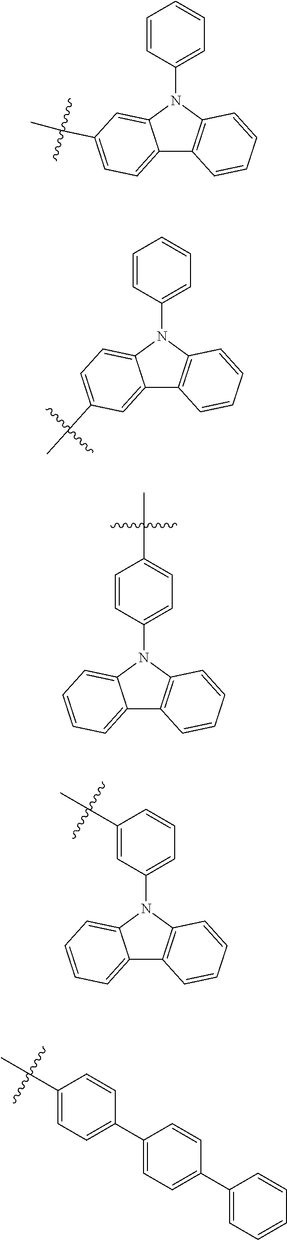
C00014

C00015
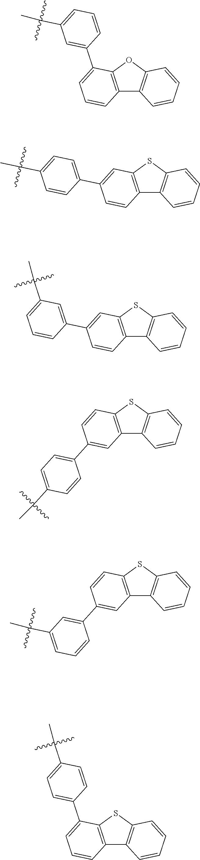
C00016

C00017
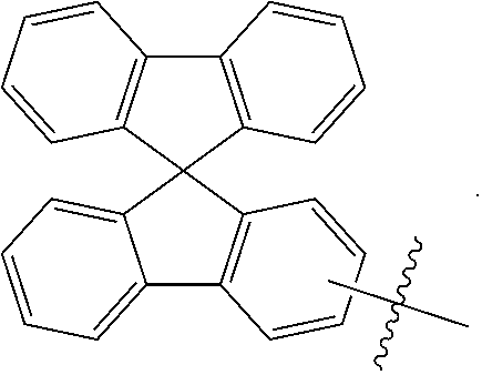
C00018
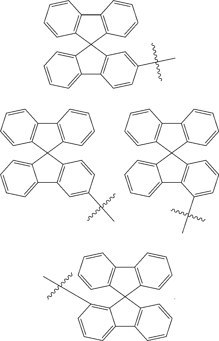
C00019
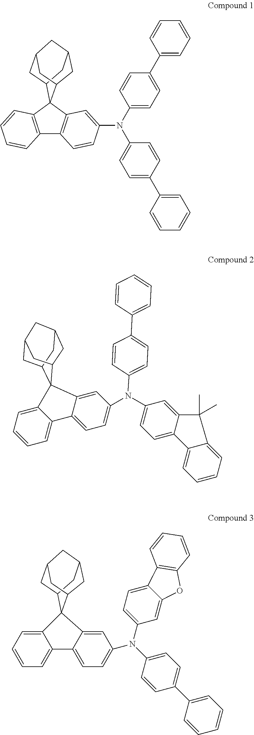
C00020

C00021
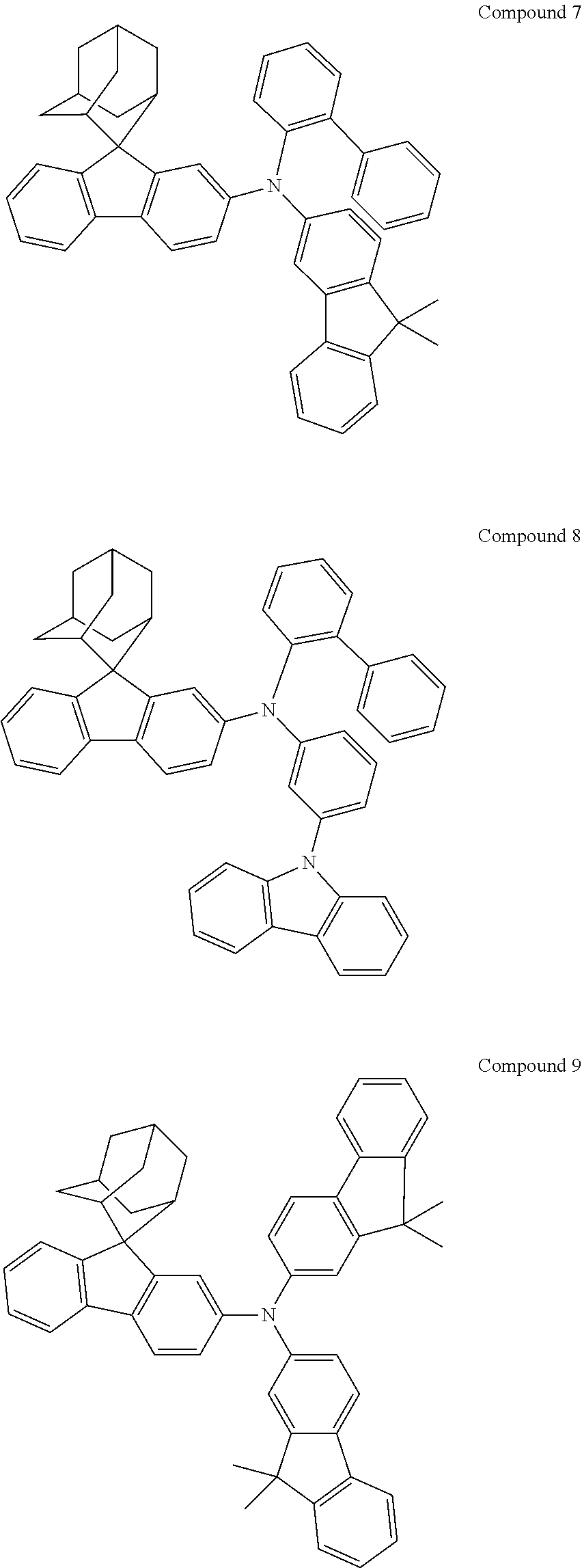
C00022
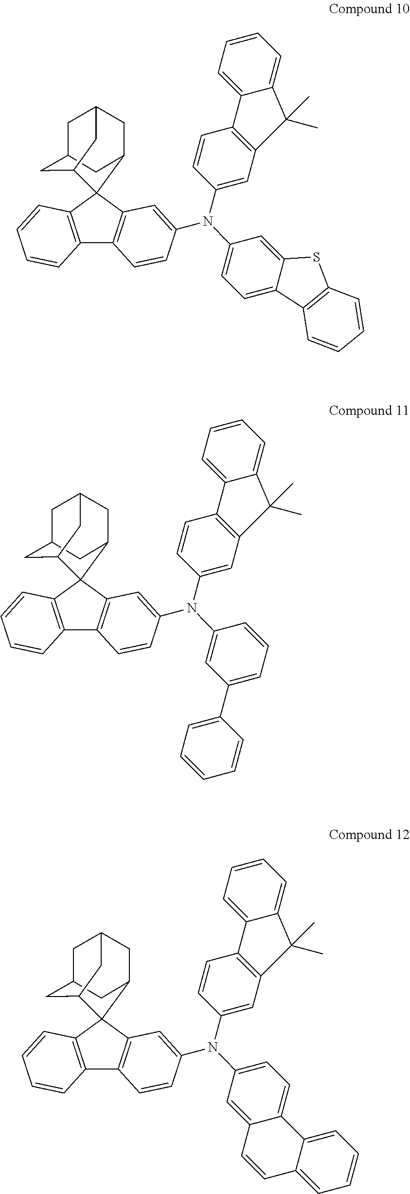
C00023
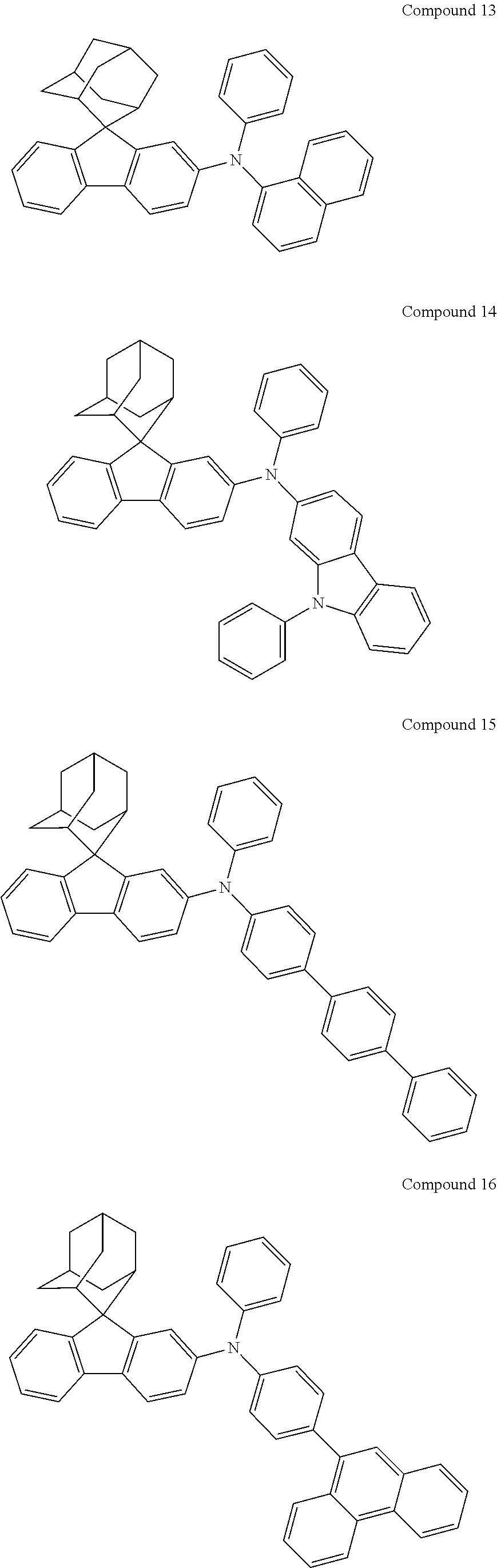
C00024

C00025
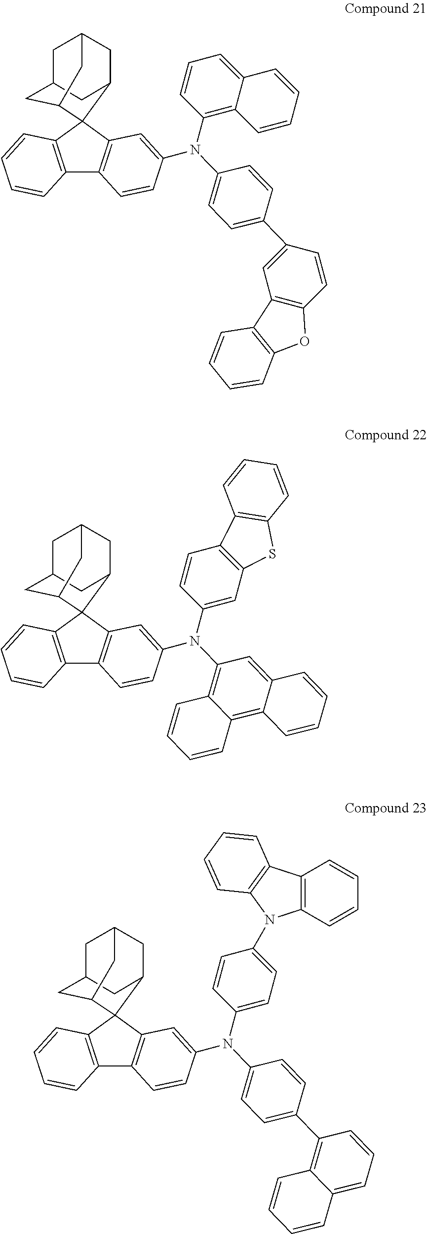
C00026

C00027
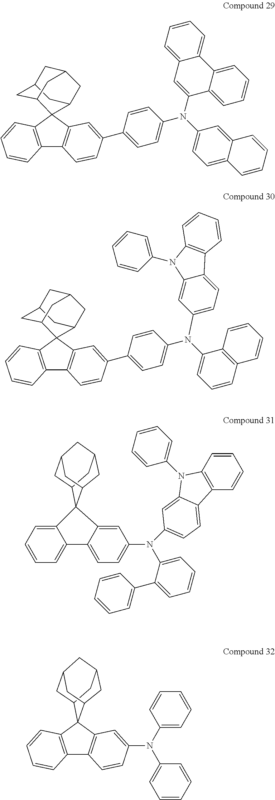
C00028
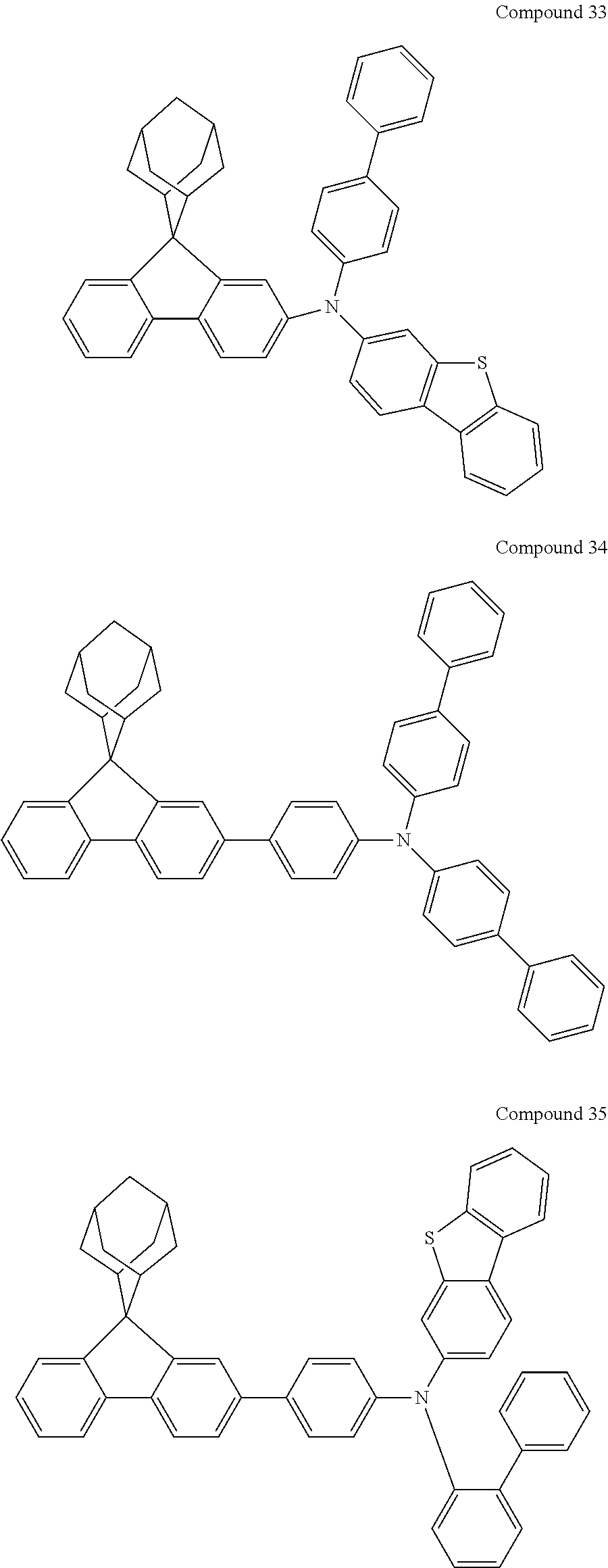
C00029
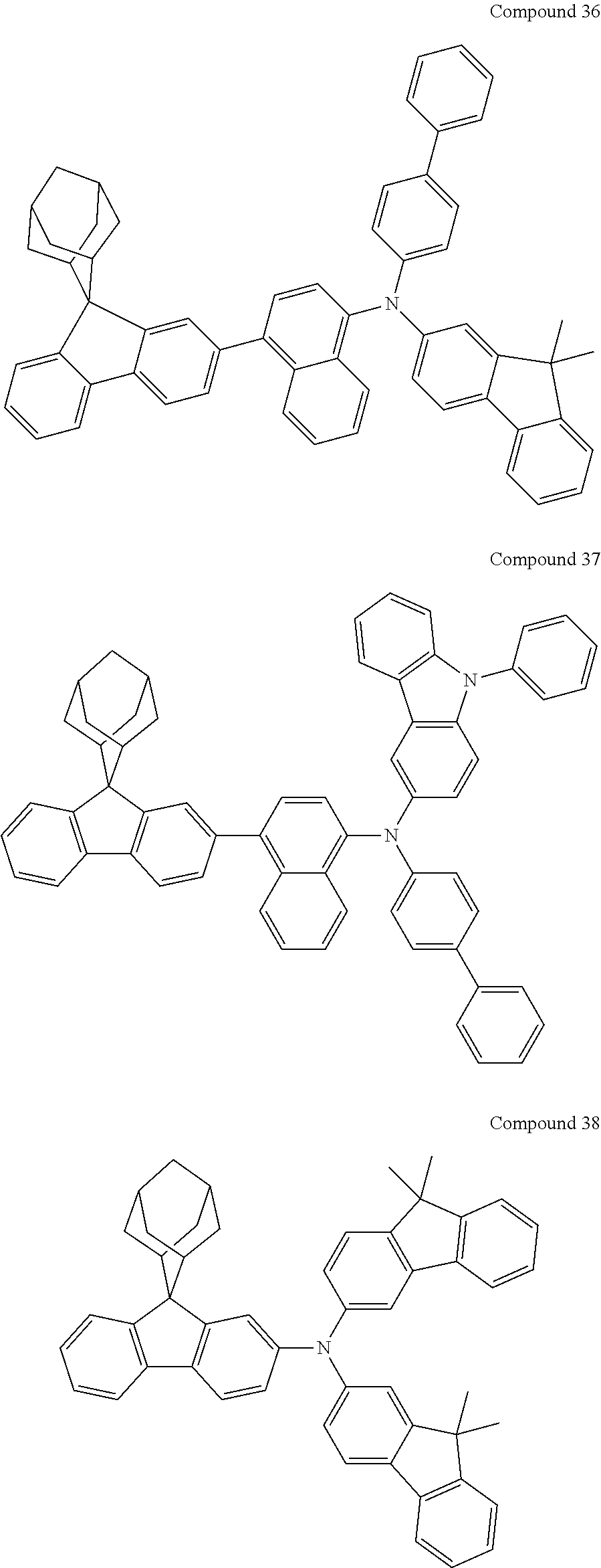
C00030

C00031
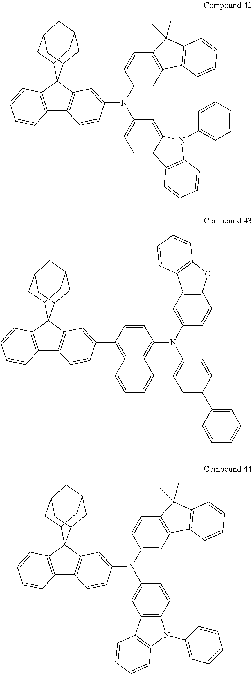
C00032

C00033
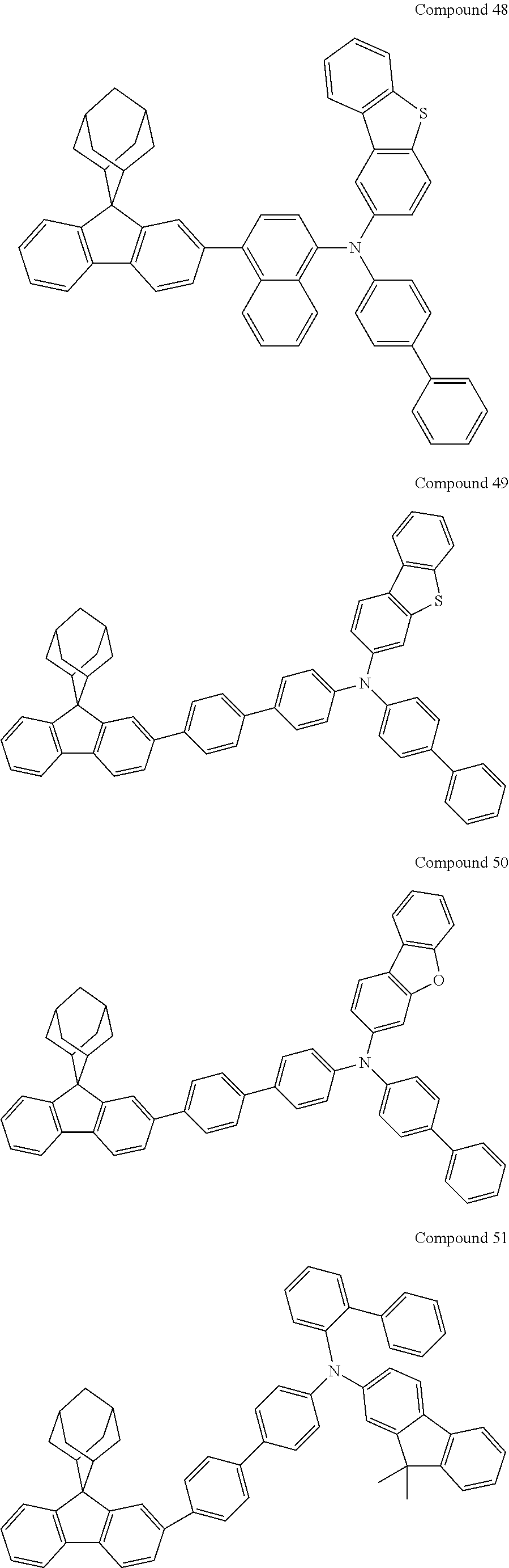
C00034
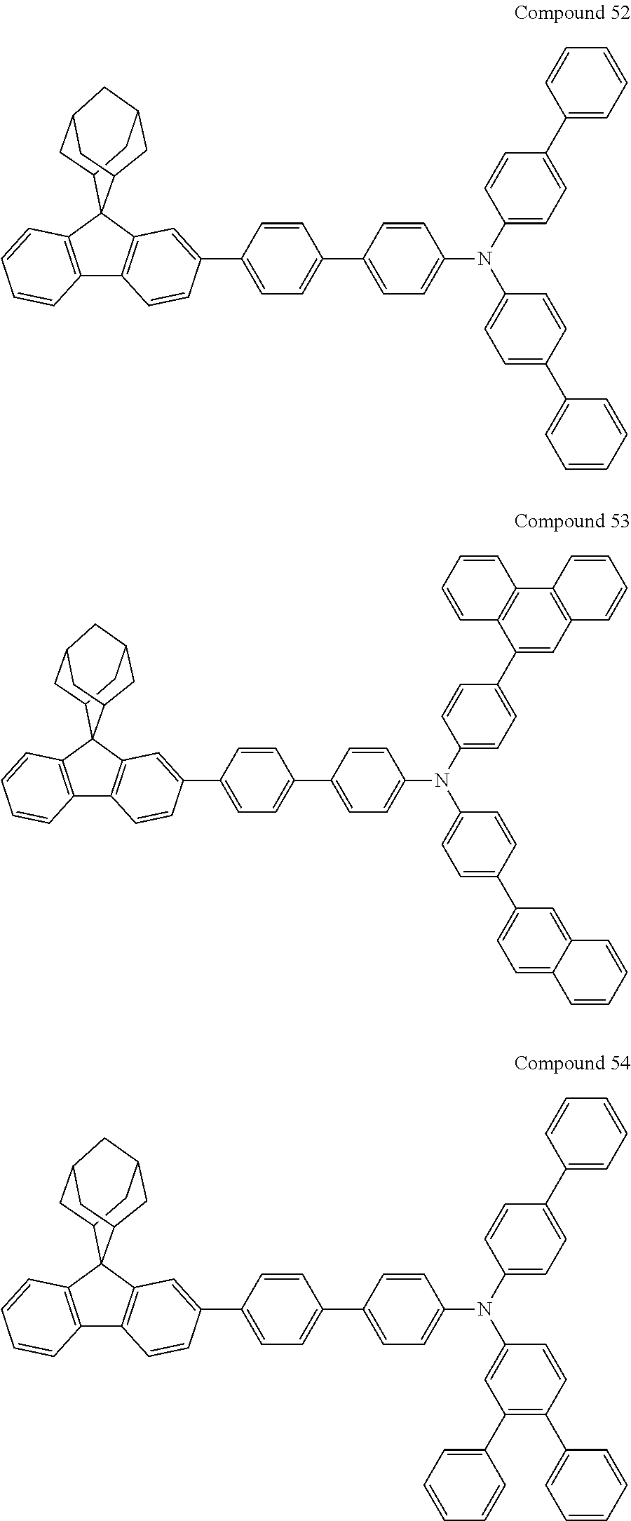
C00035
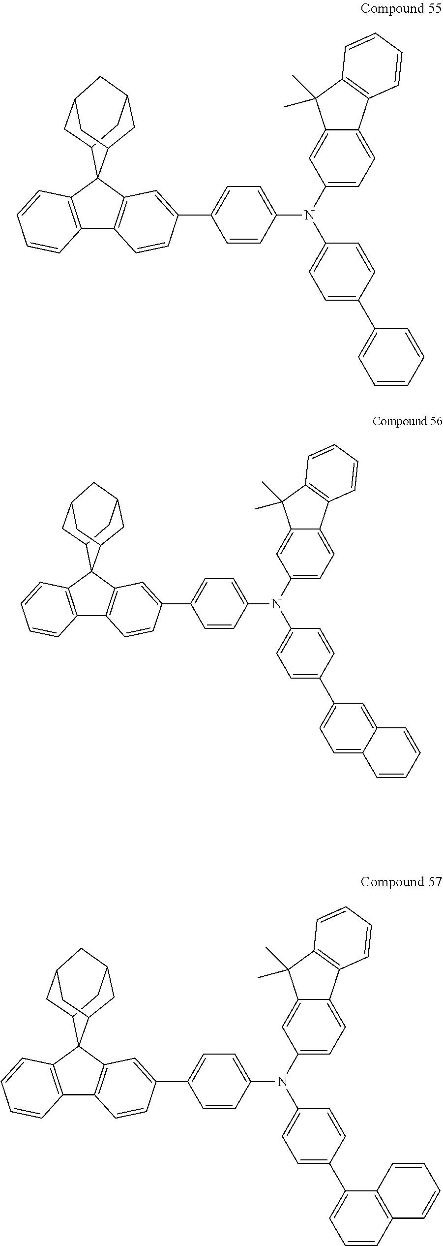
C00036
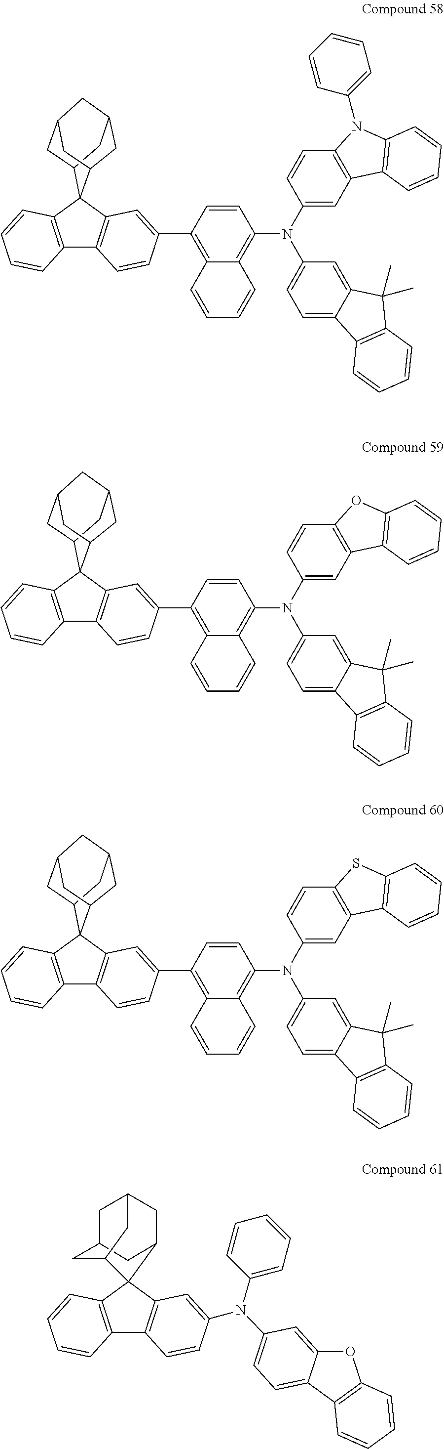
C00037
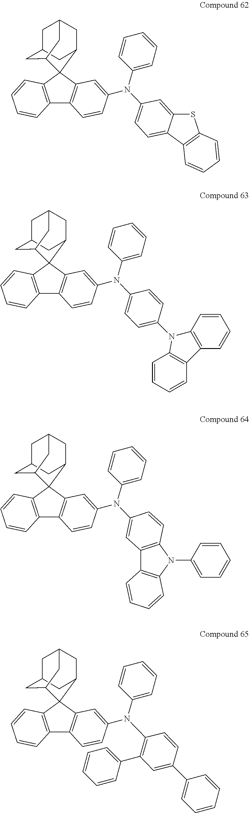
C00038

C00039
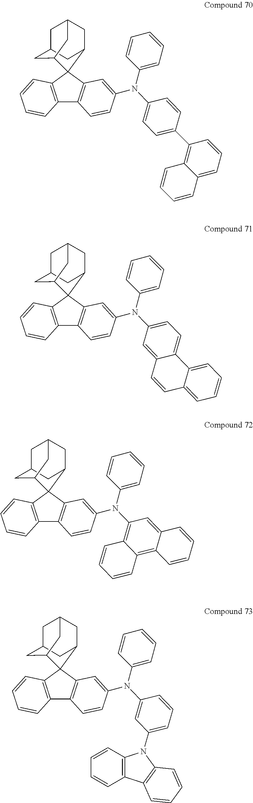
C00040

C00041
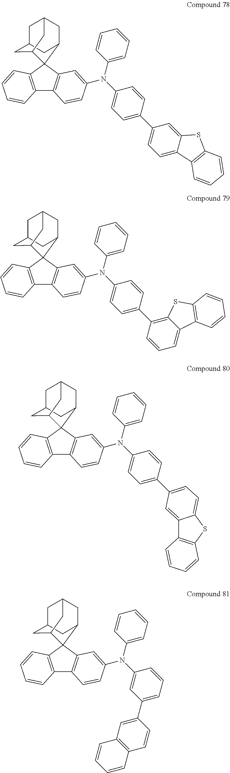
C00042

C00043
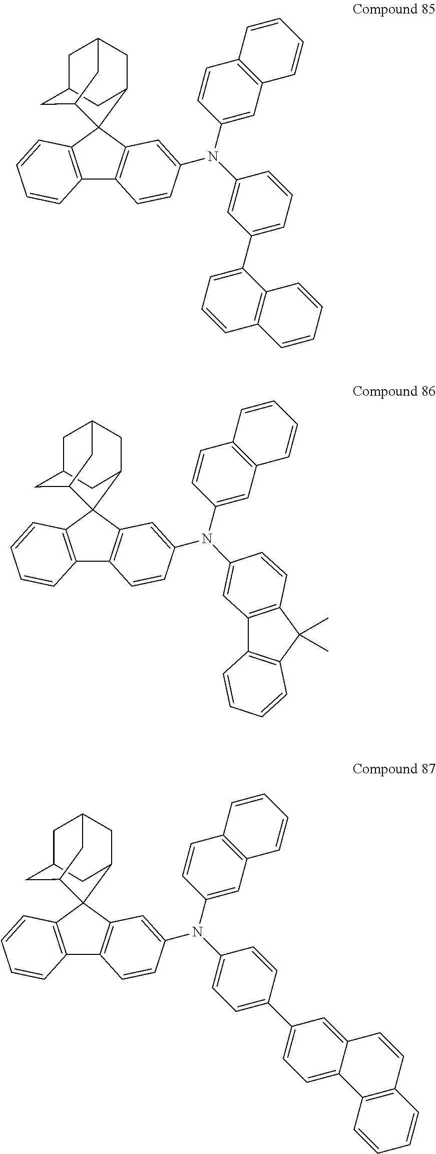
C00044

C00045
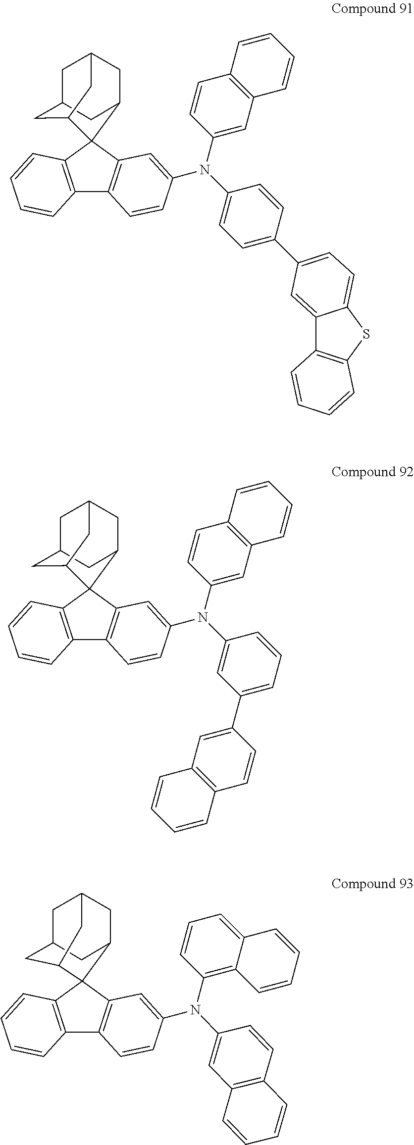
C00046
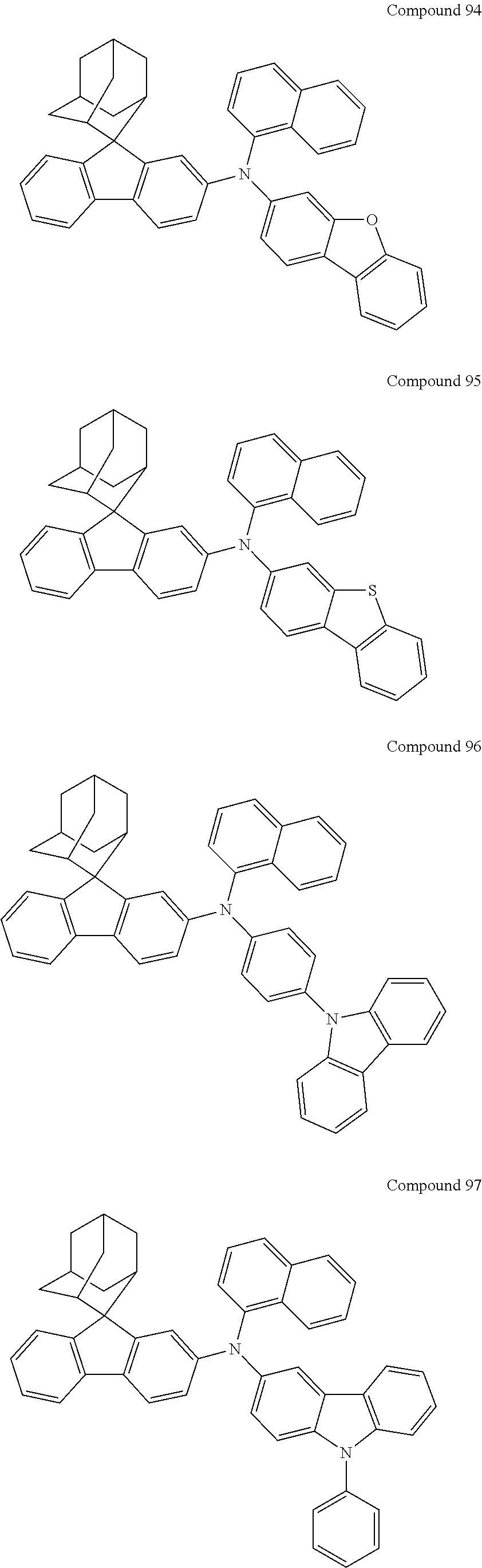
C00047

C00048

C00049
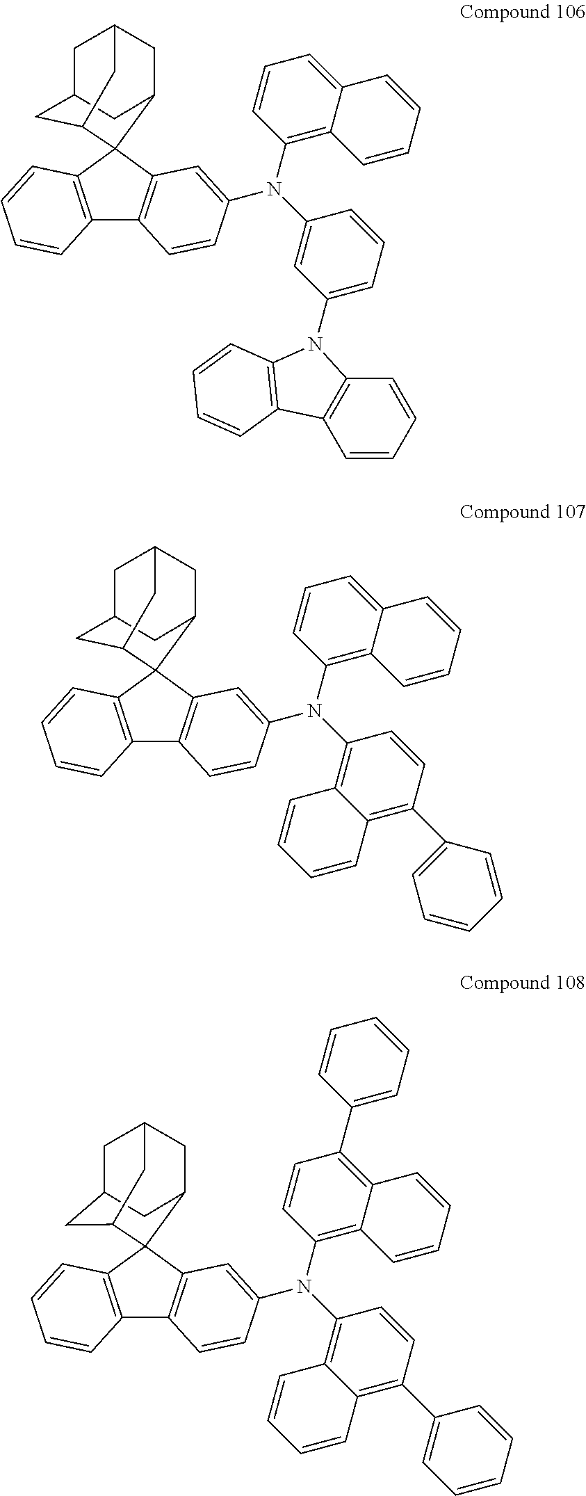
C00050
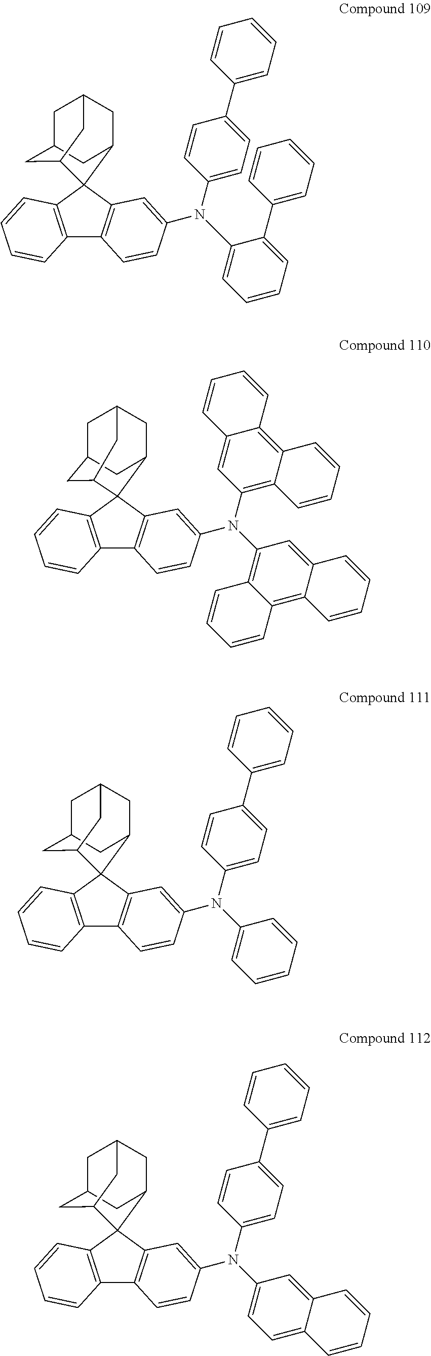
C00051
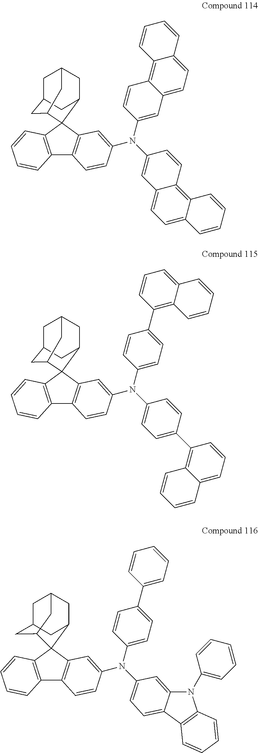
C00052
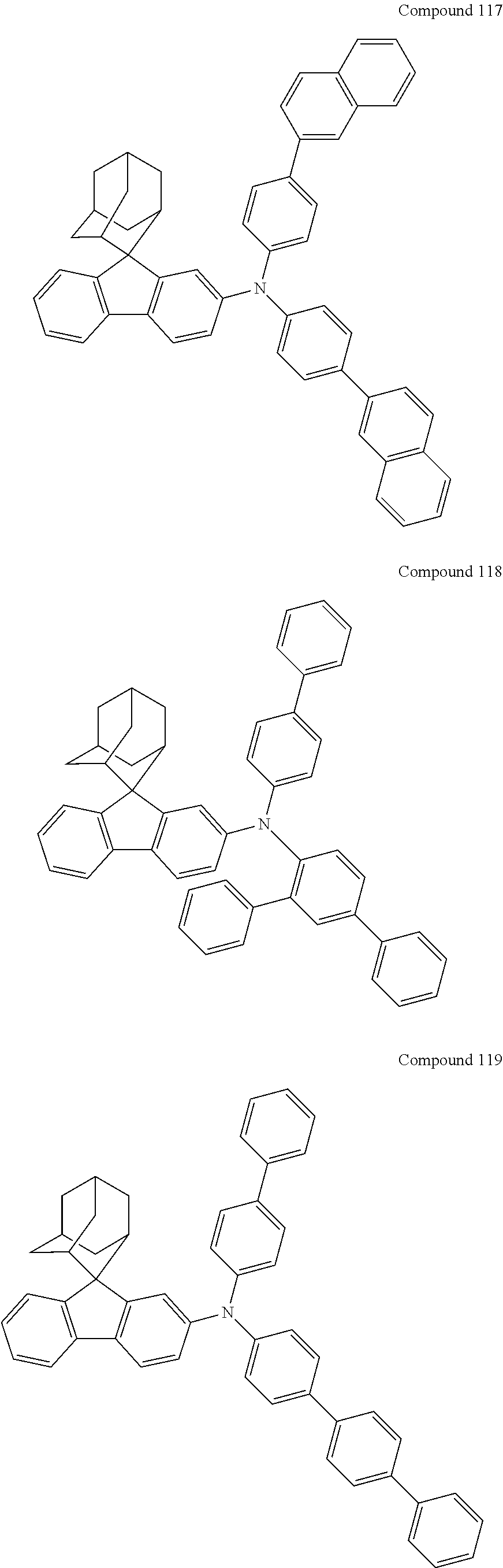
C00053
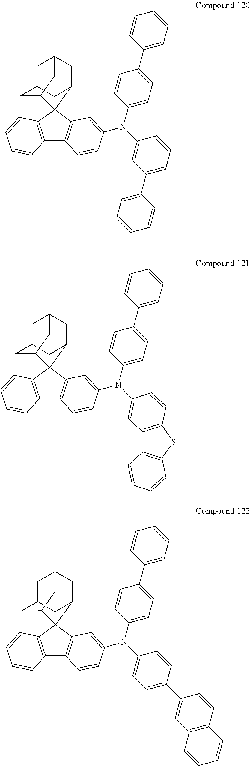
C00054
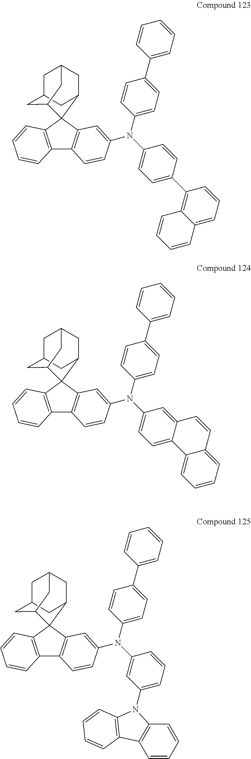
C00055
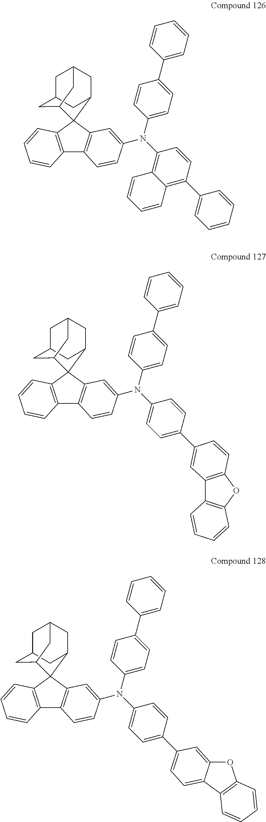
C00056
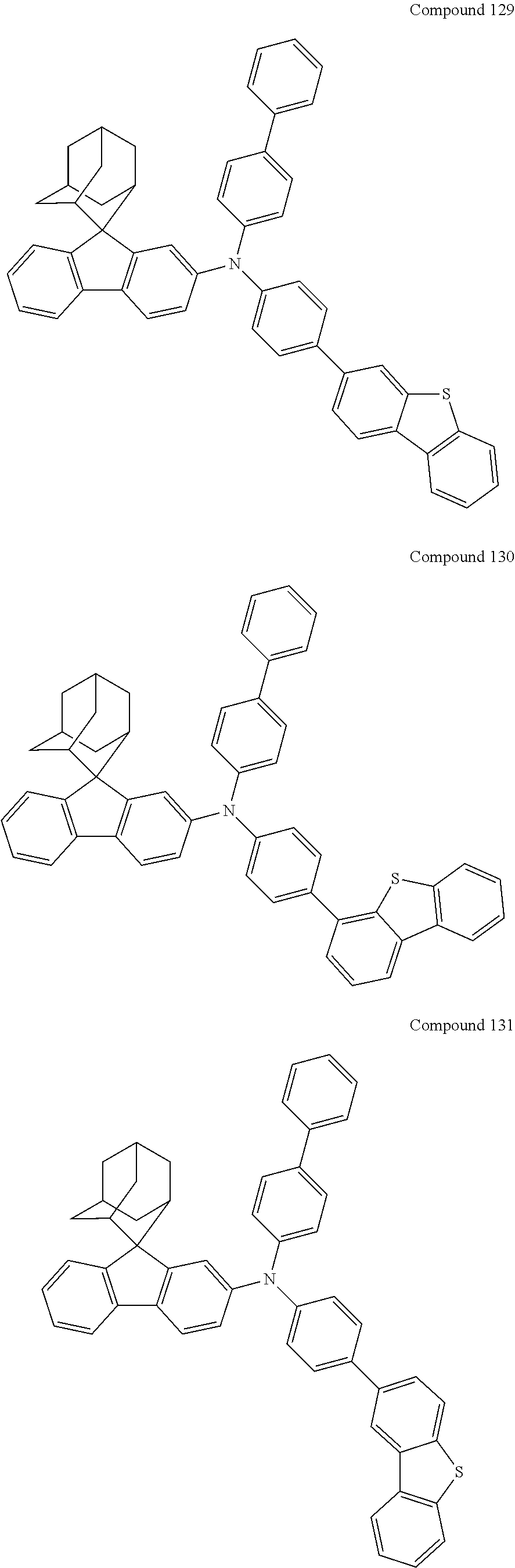
C00057
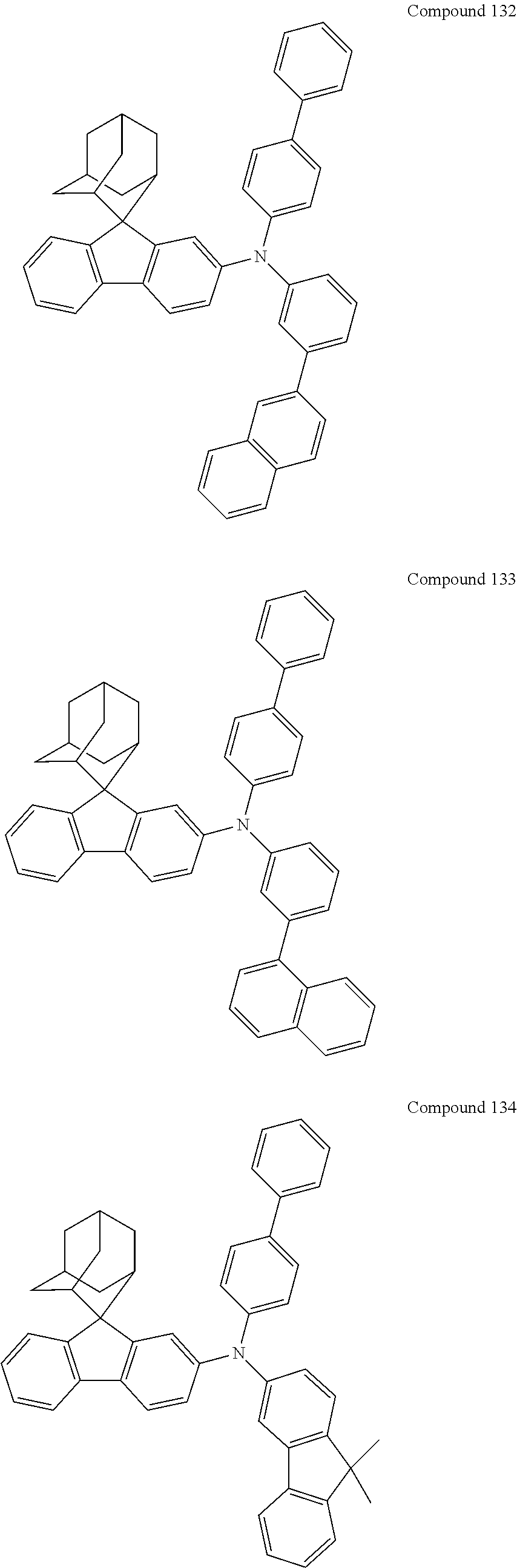
C00058

C00059

C00060
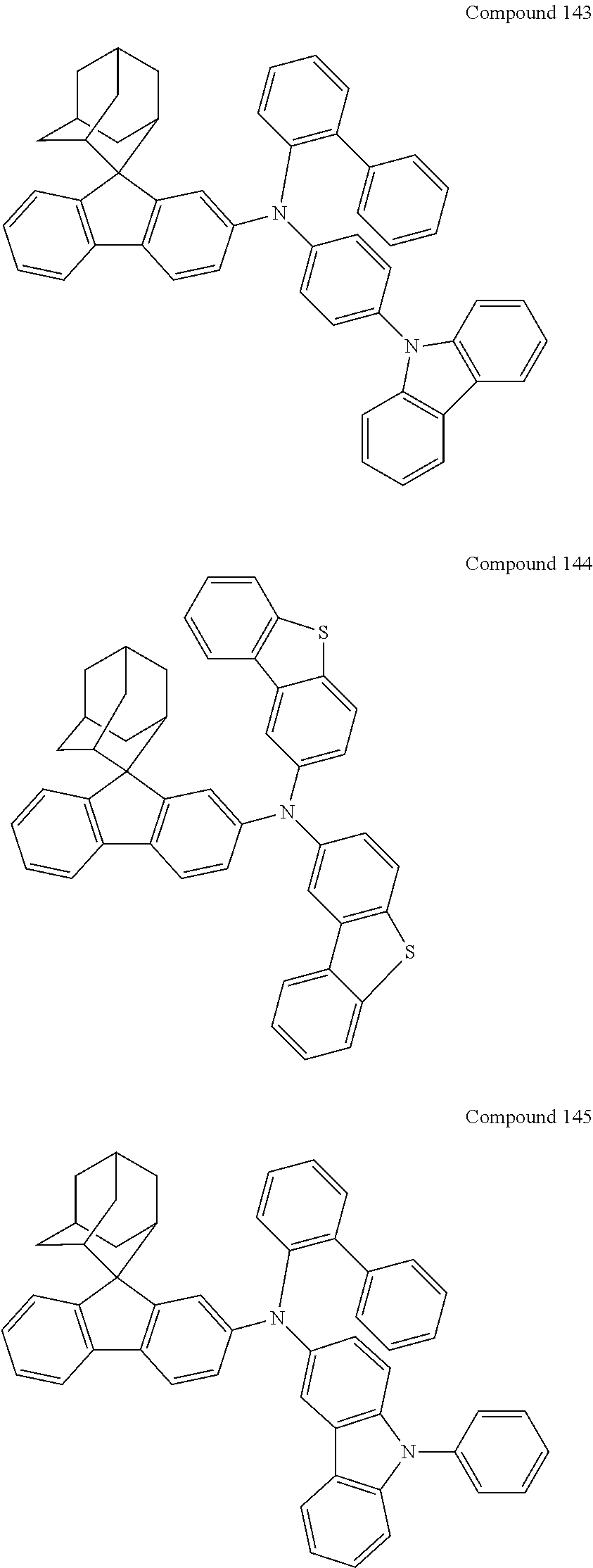
C00061

C00062
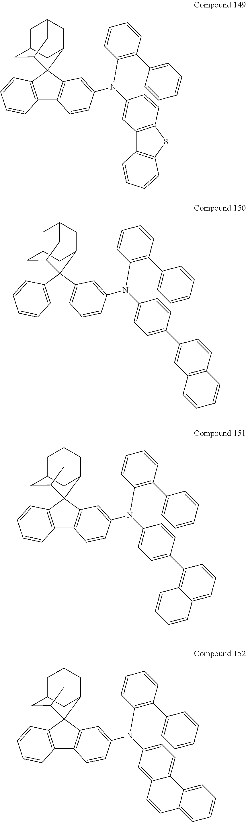
C00063

C00064
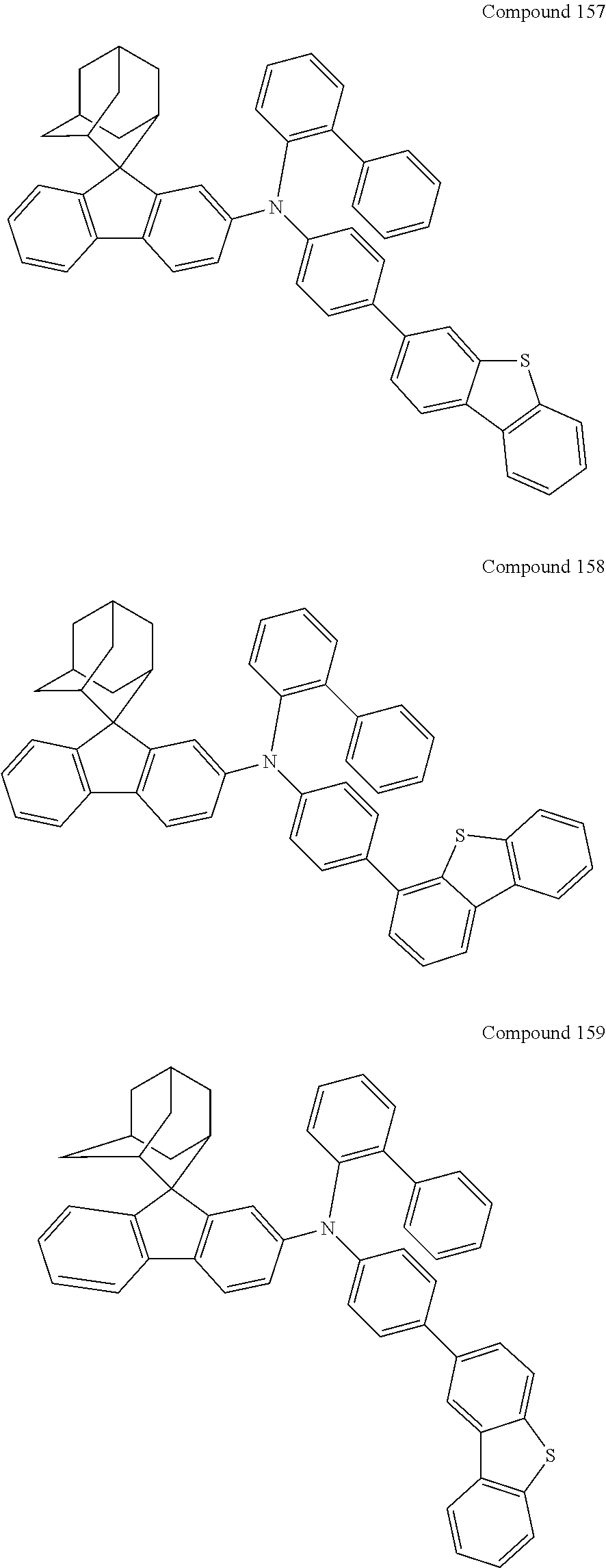
C00065
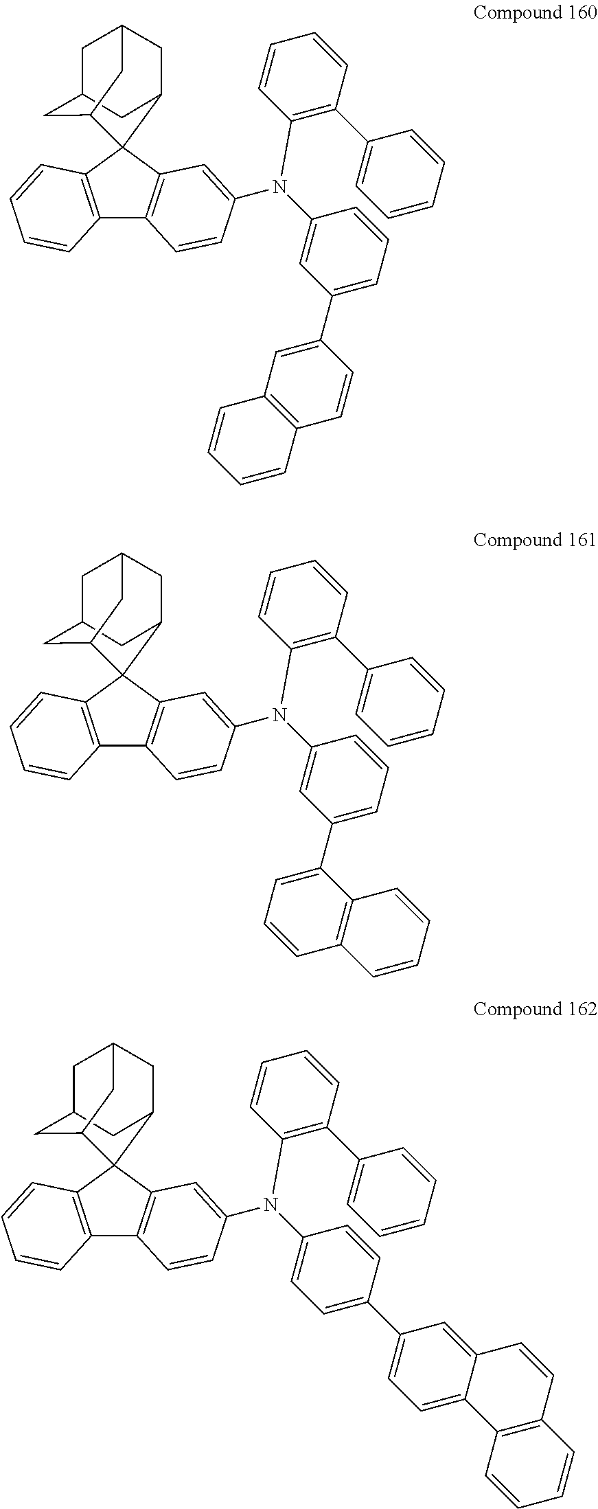
C00066

C00067
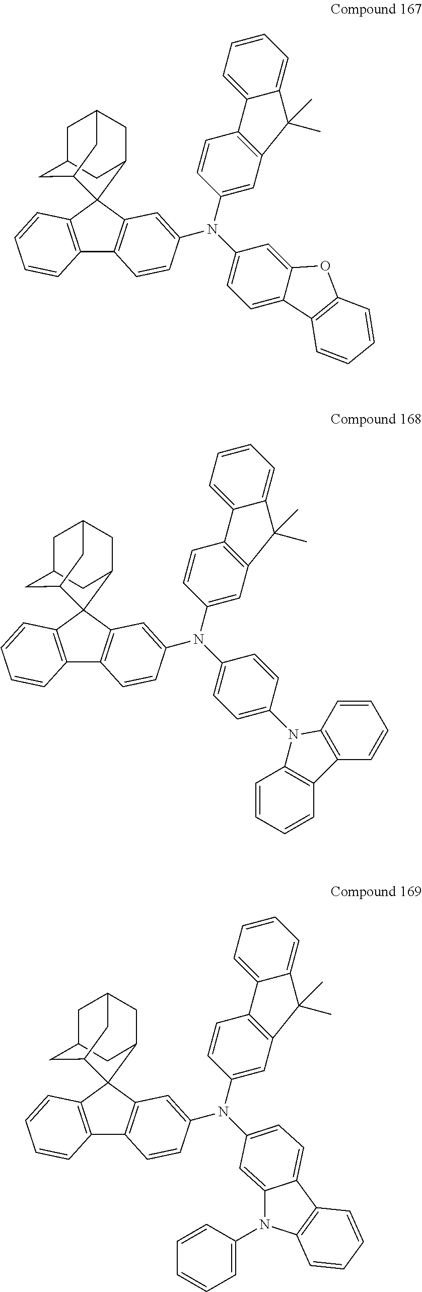
C00068
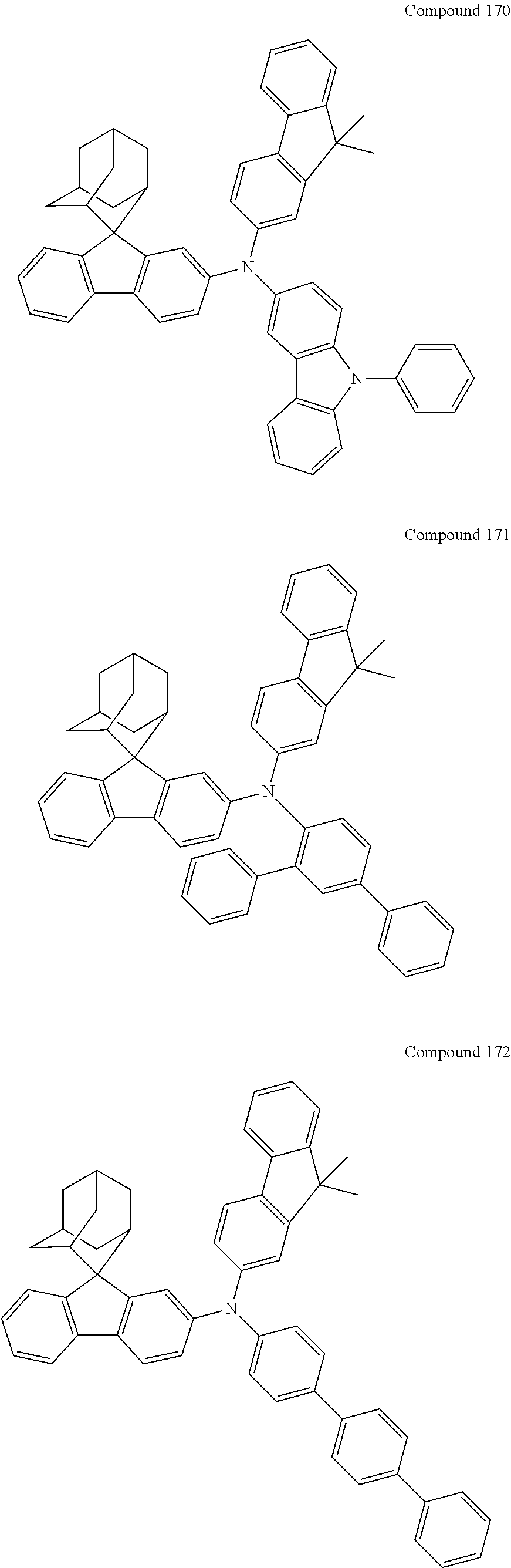
C00069

C00070
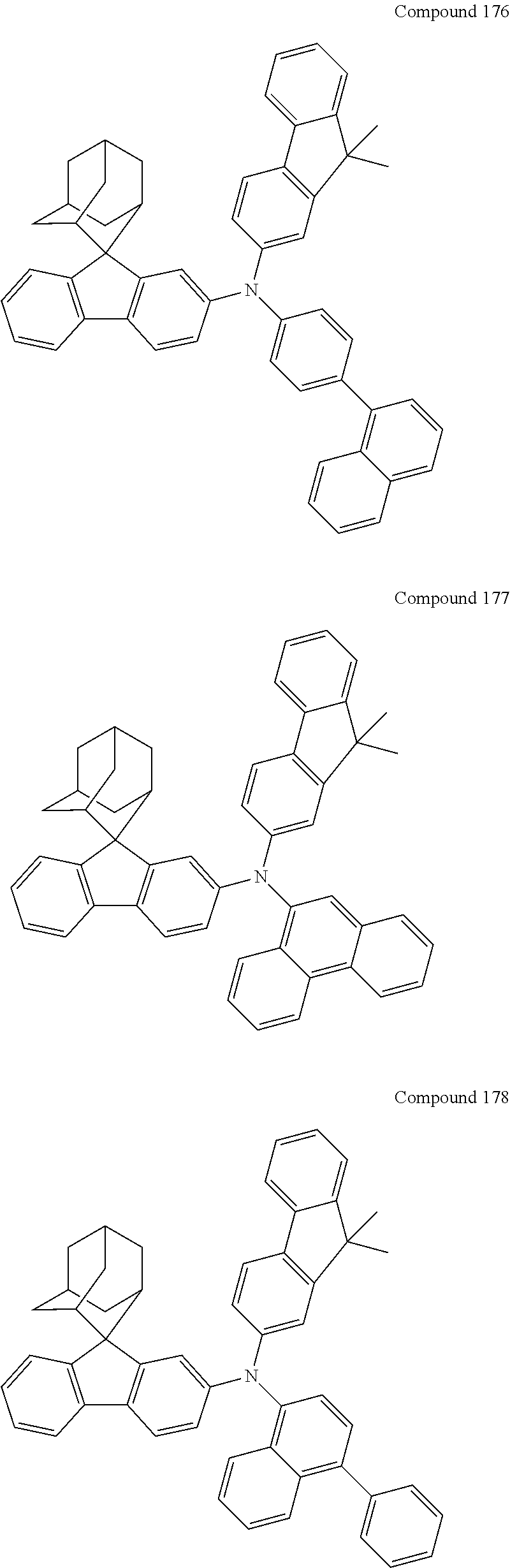
C00071

C00072
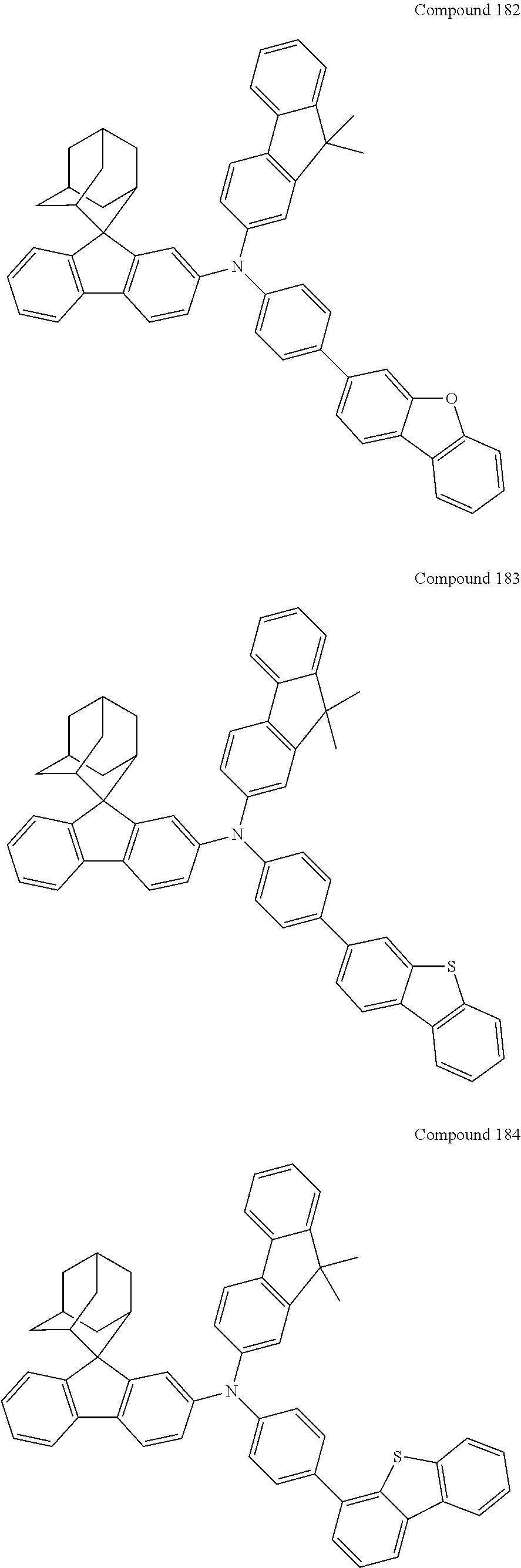
C00073
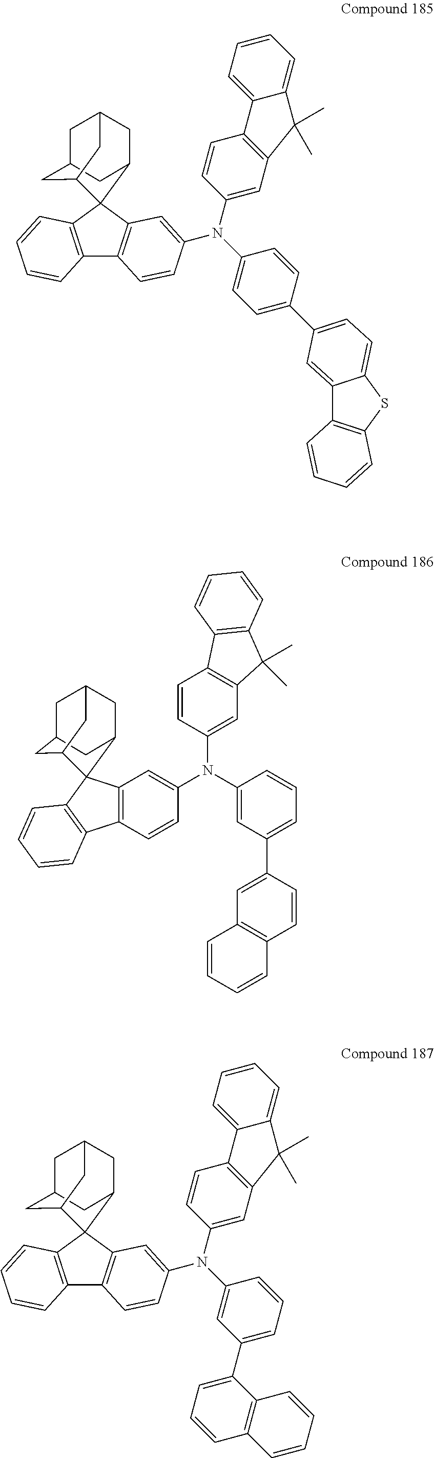
C00074
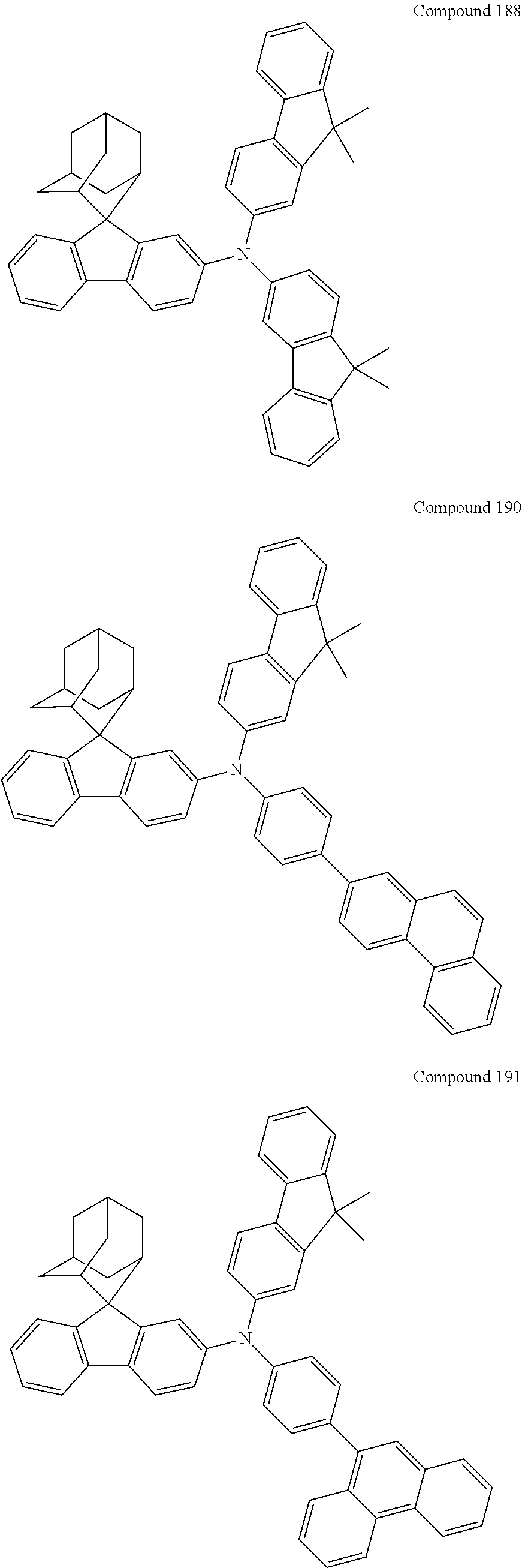
C00075
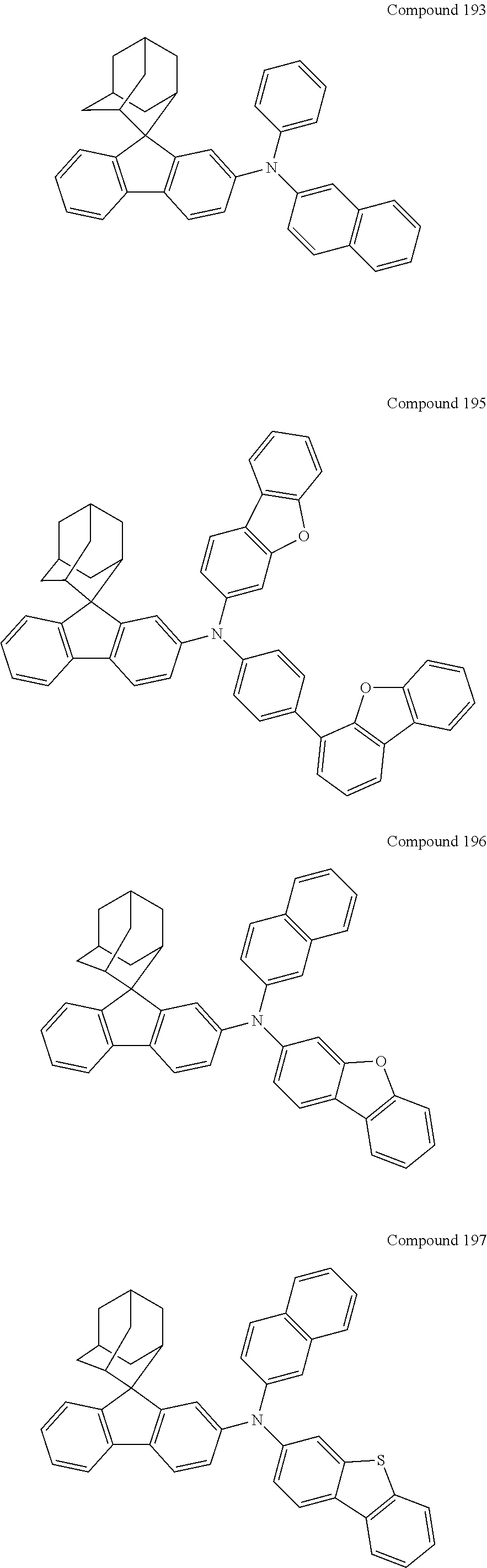
C00076
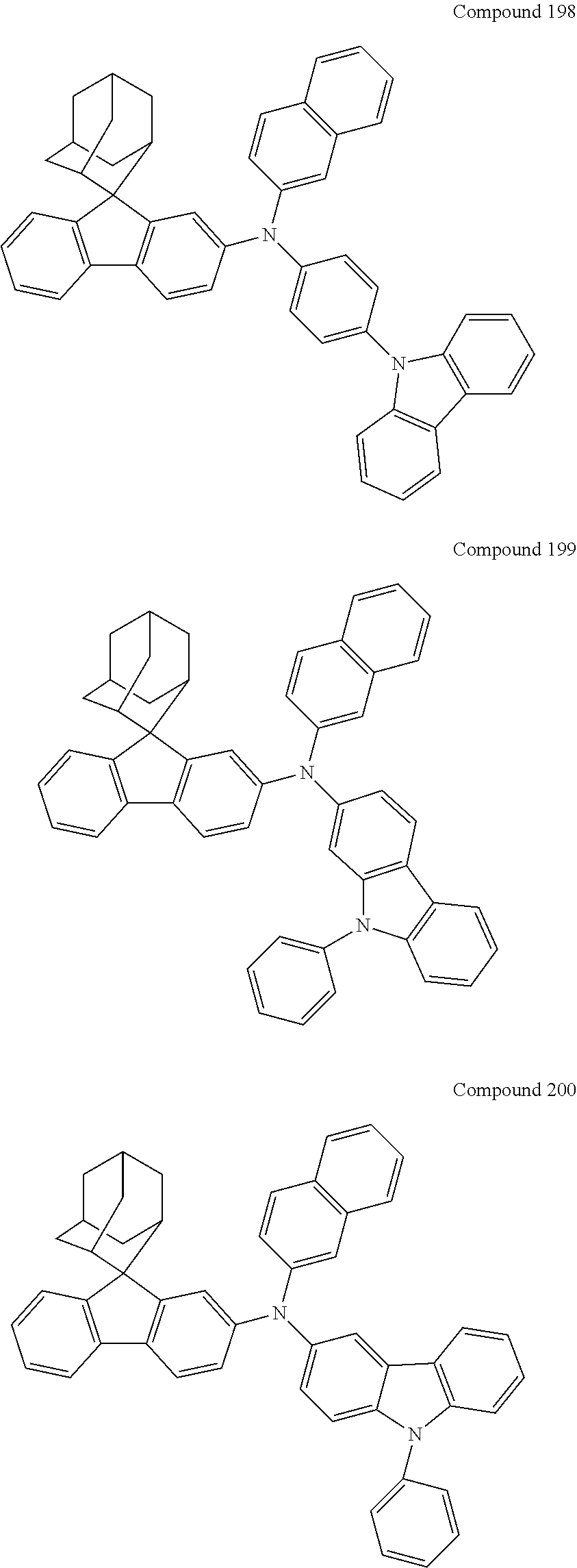
C00077
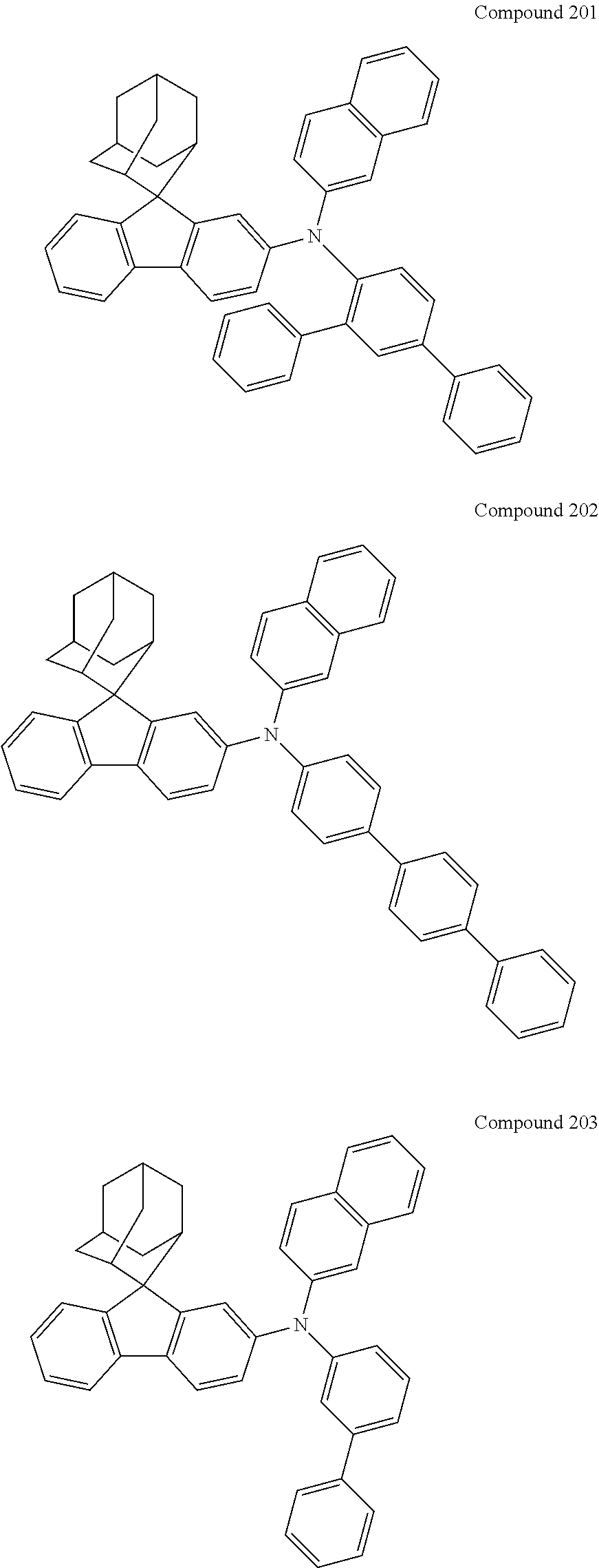
C00078
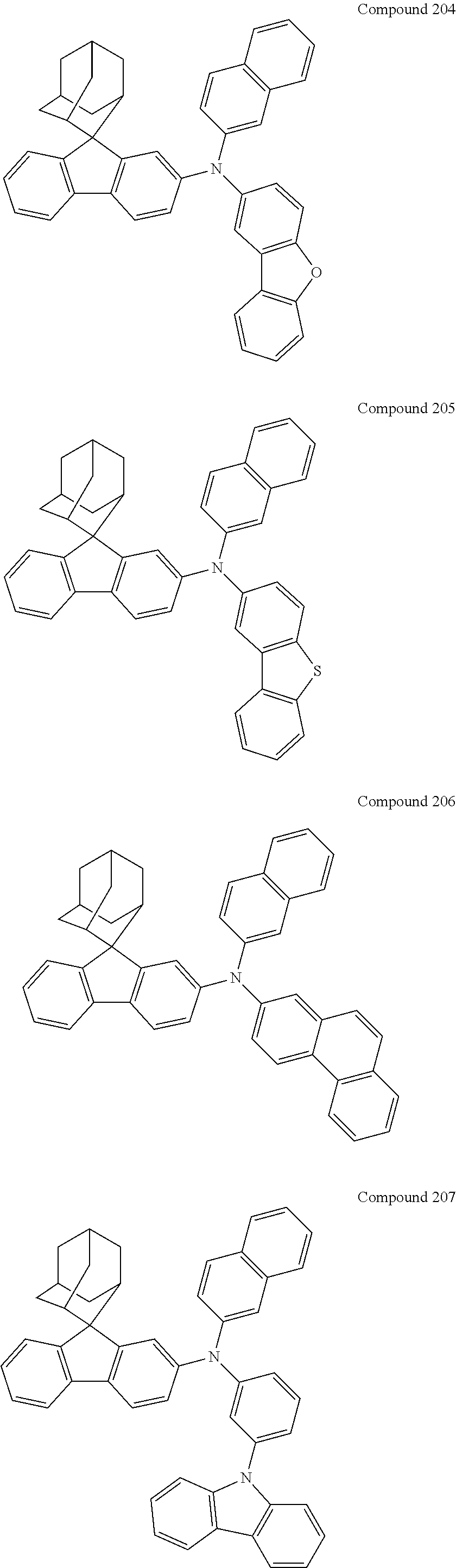
C00079

C00080

C00081
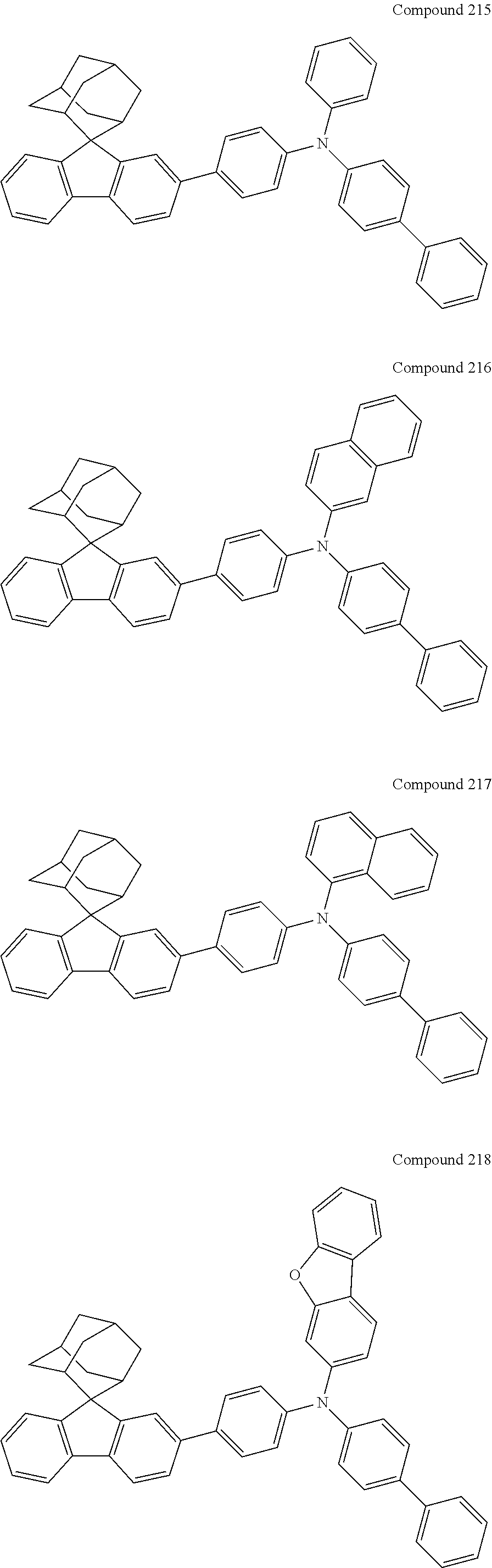
C00082

C00083

C00084

C00085
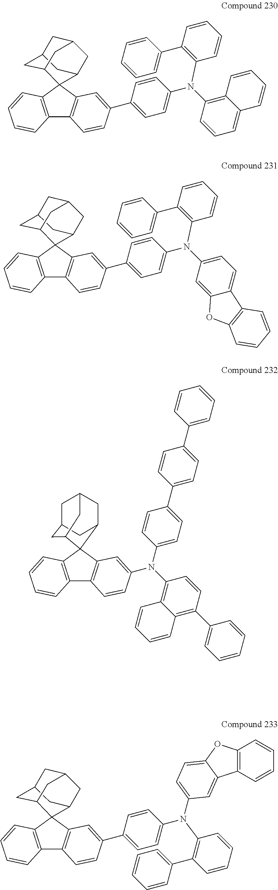
C00086
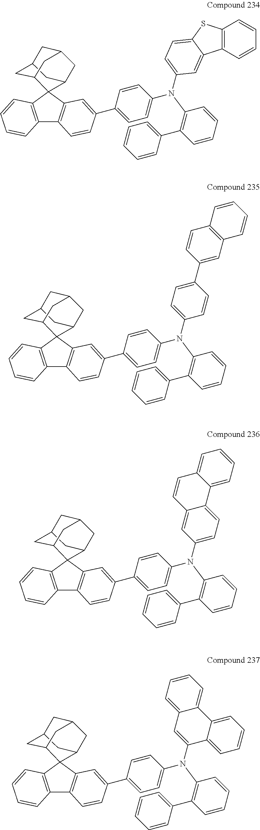
C00087
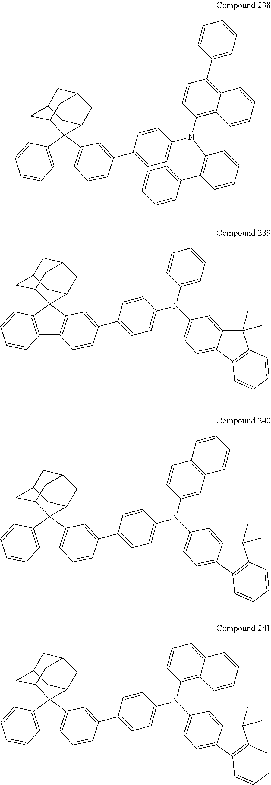
C00088
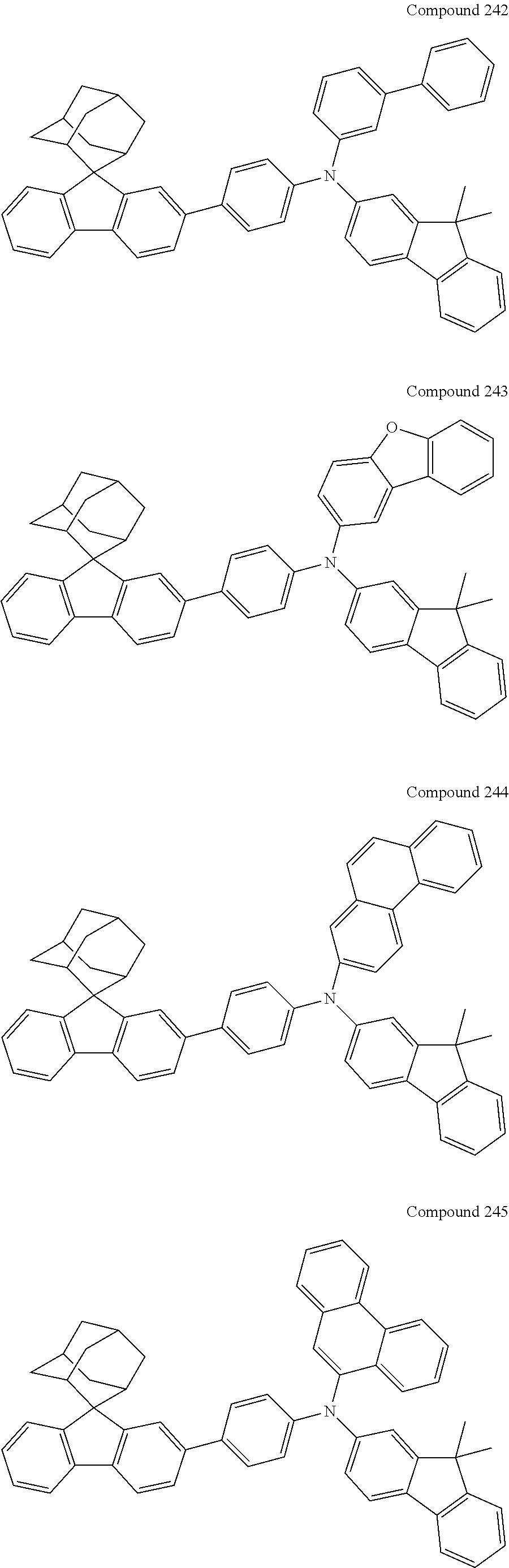
C00089

C00090
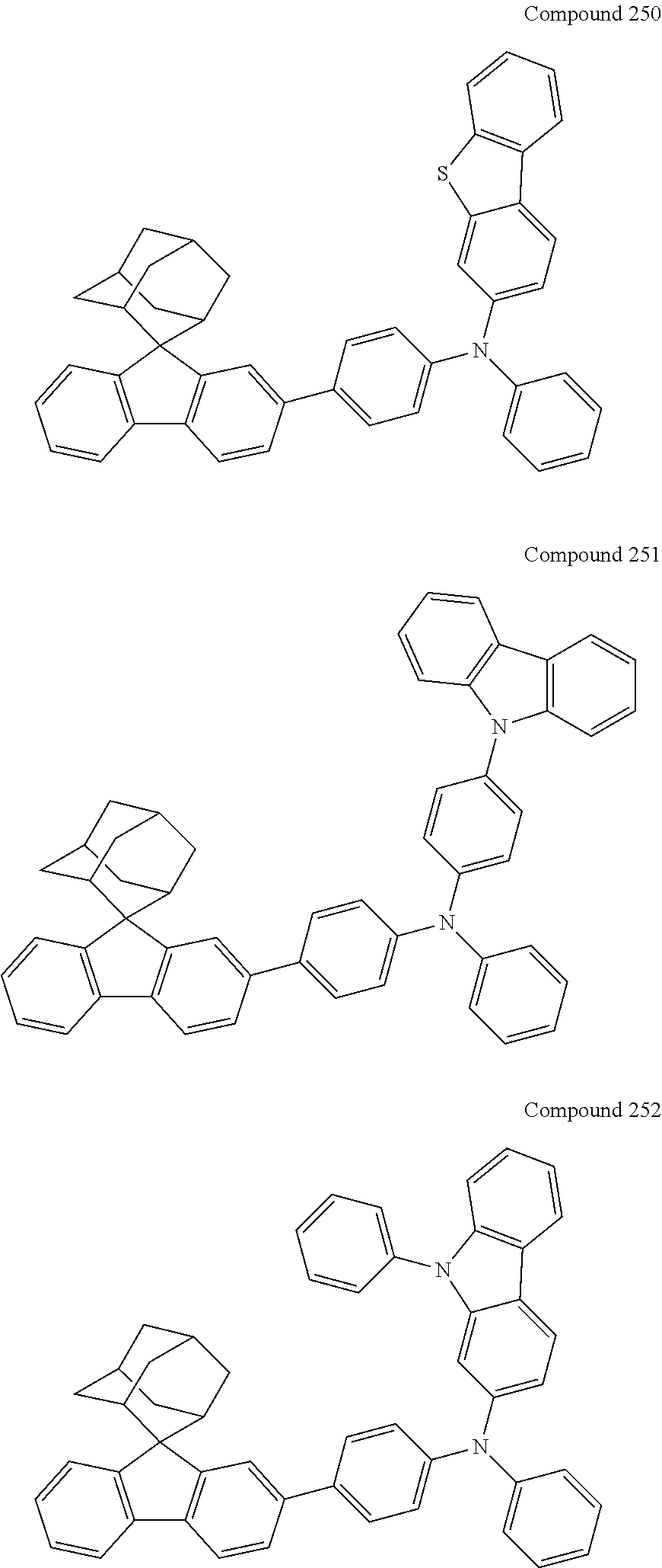
C00091
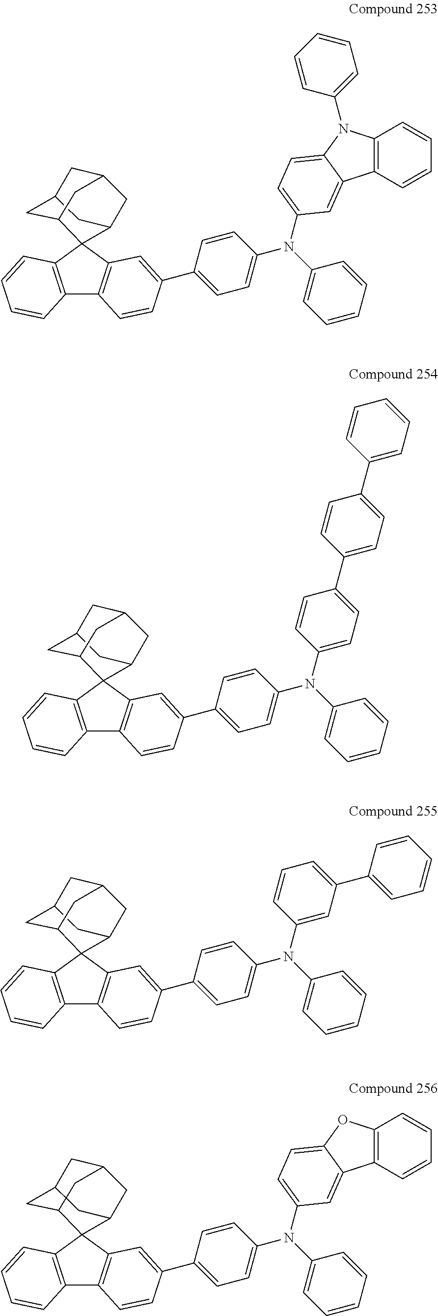
C00092

C00093
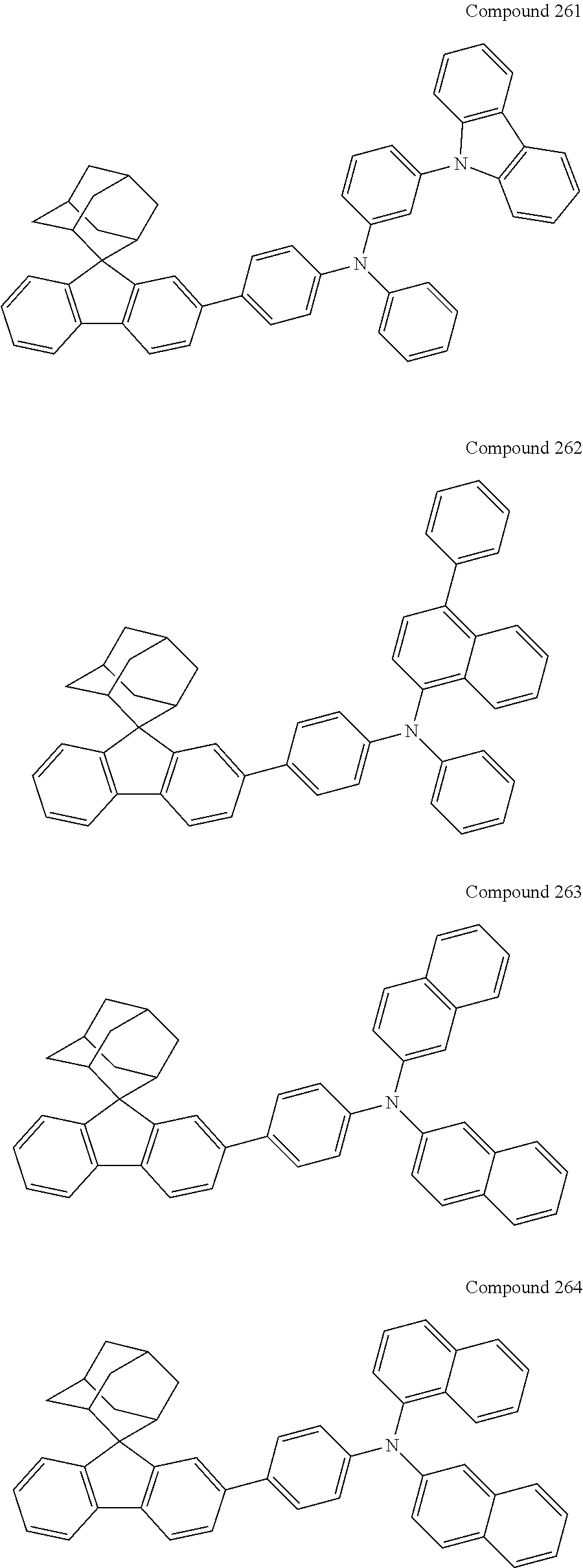
C00094
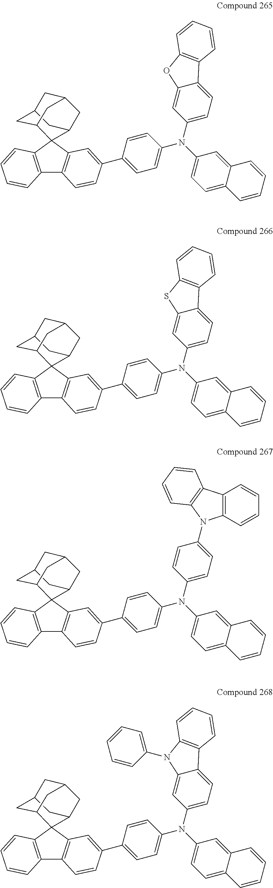
C00095
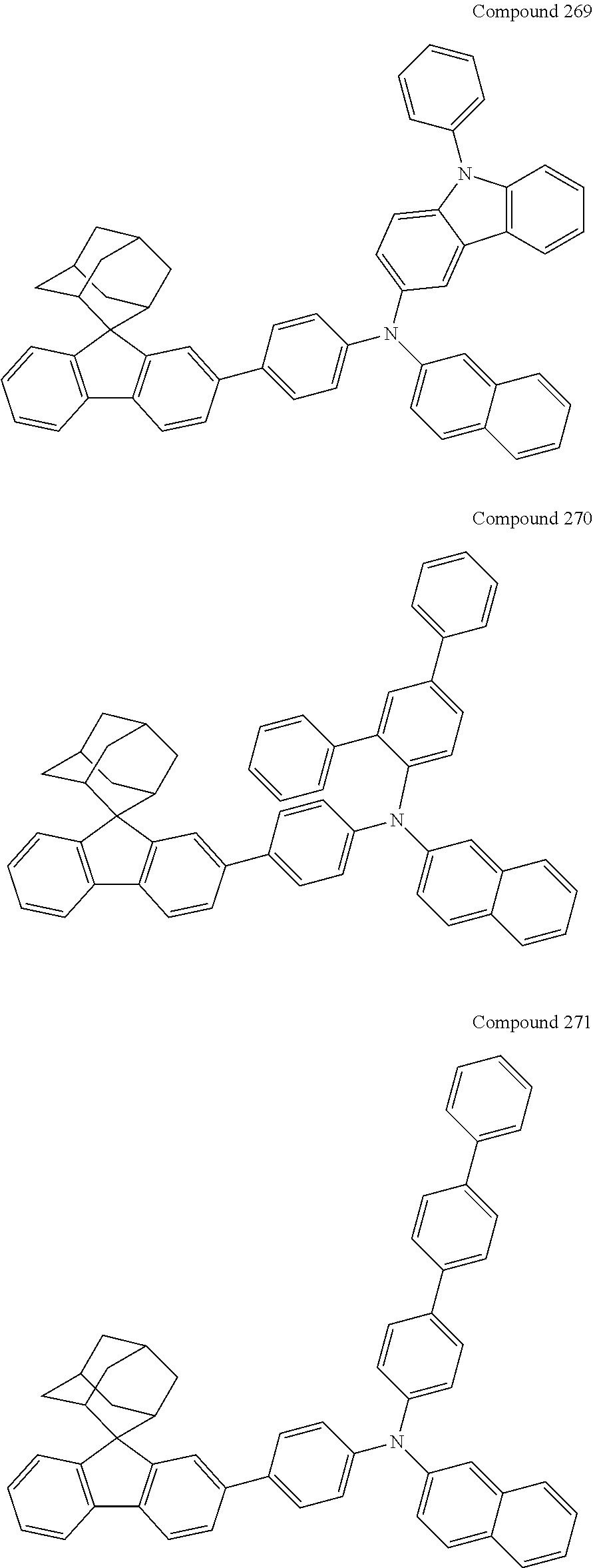
C00096
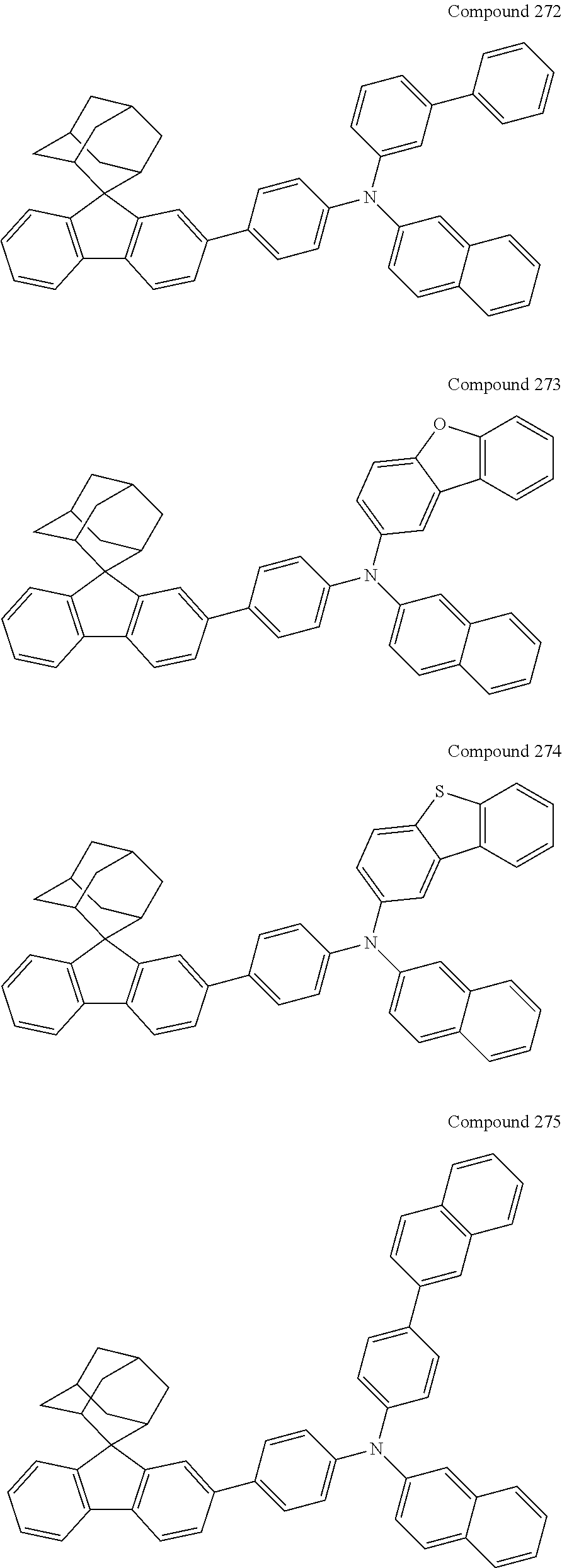
C00097
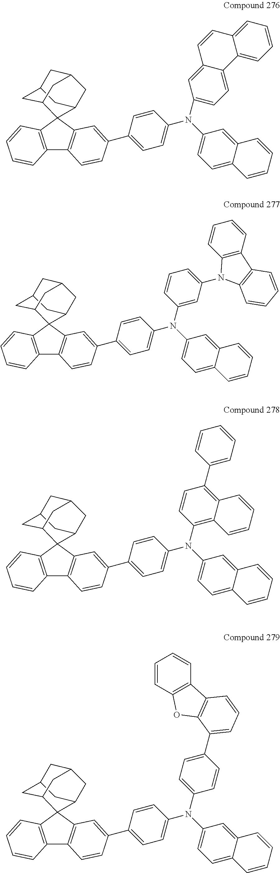
C00098

C00099
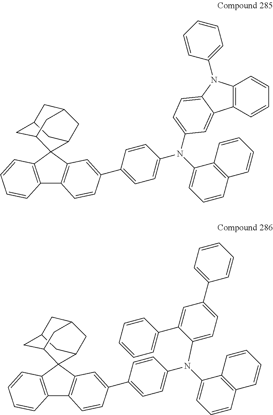
C00100

C00101
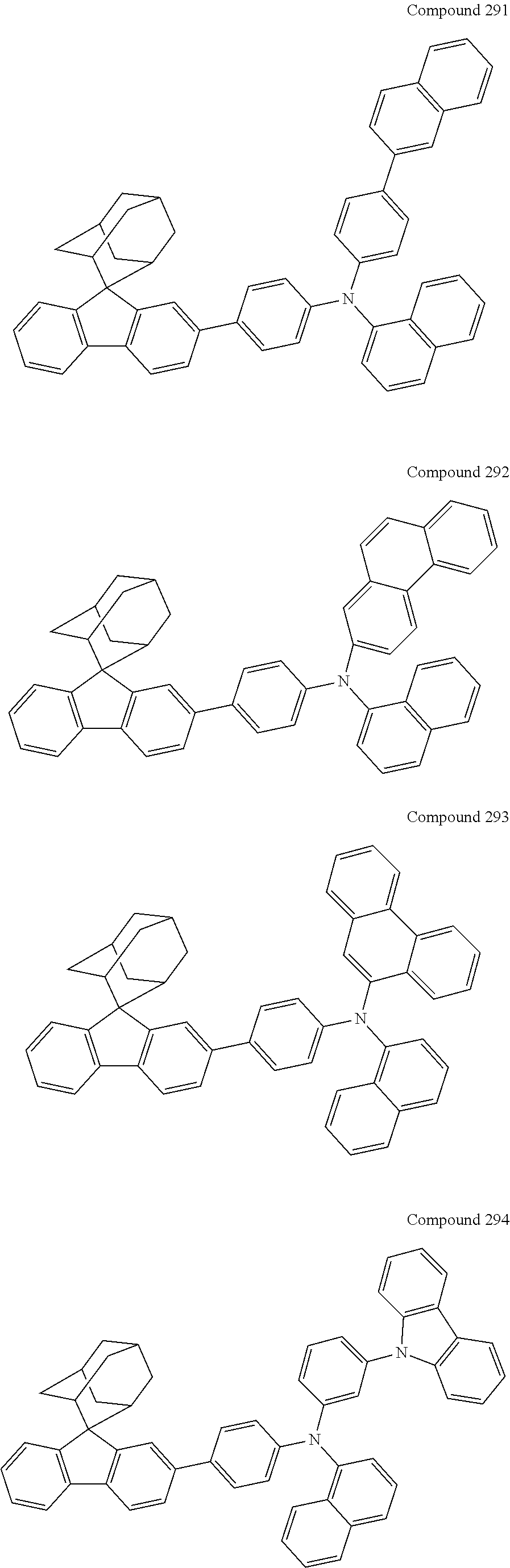
C00102
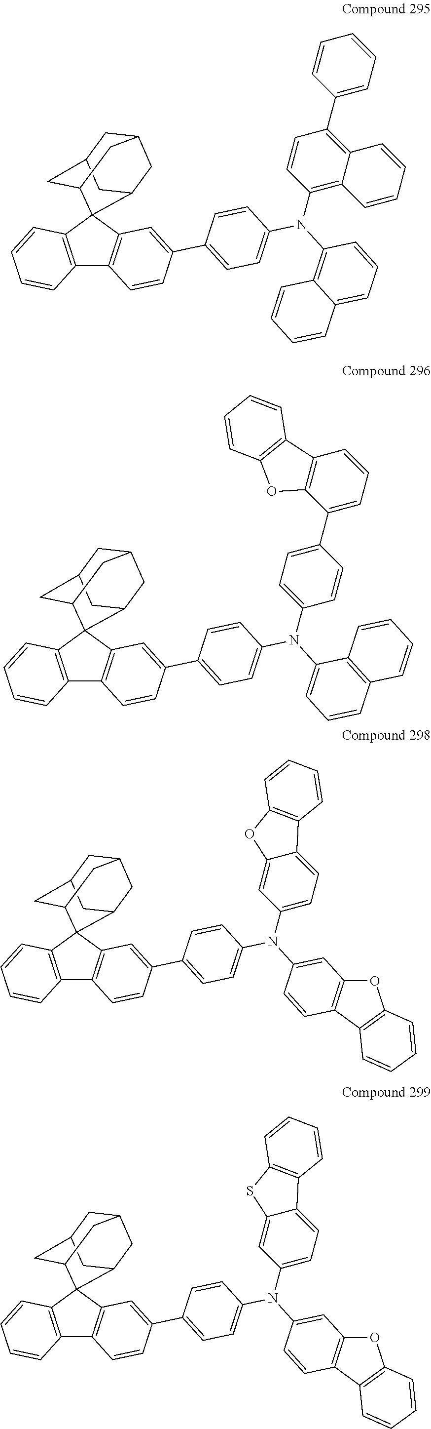
C00103
C00104
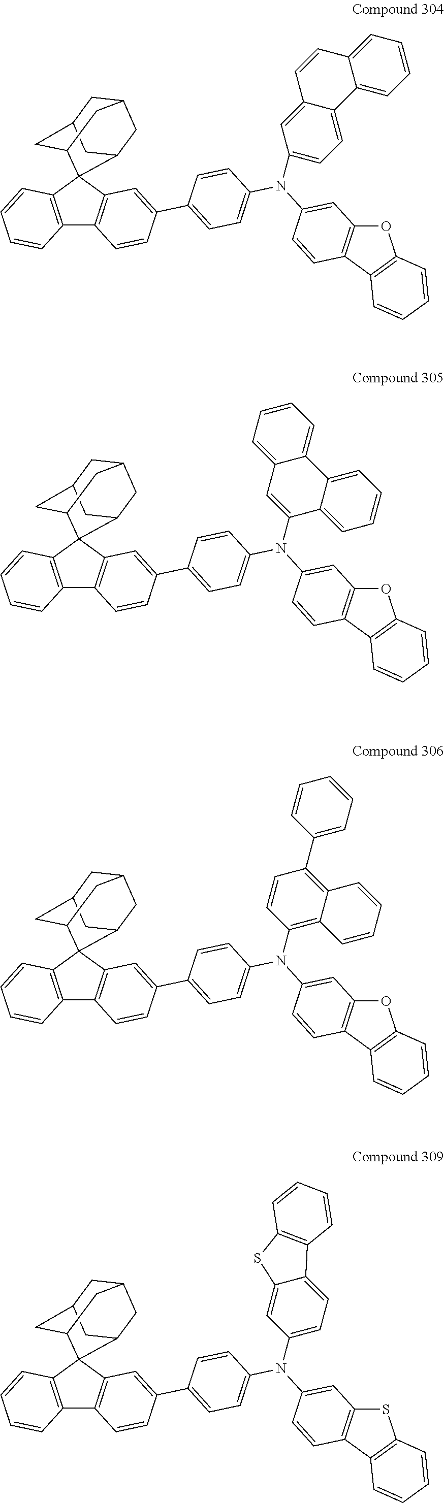
C00105
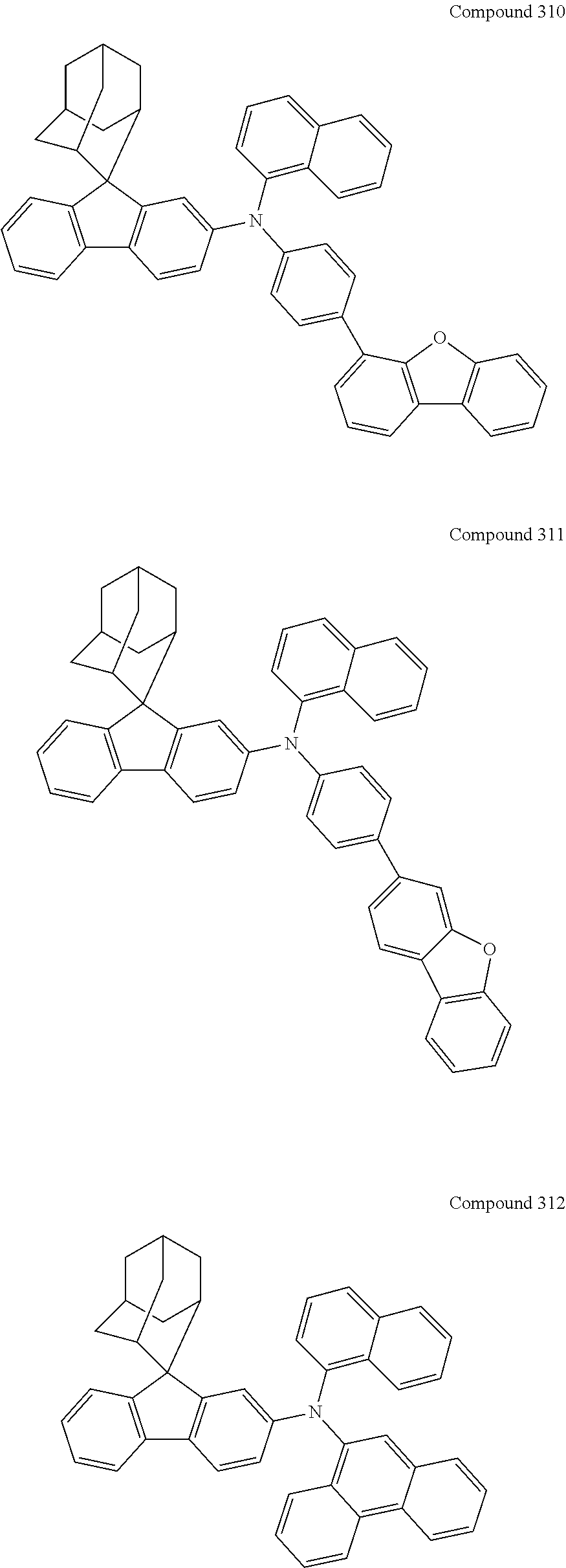
C00106
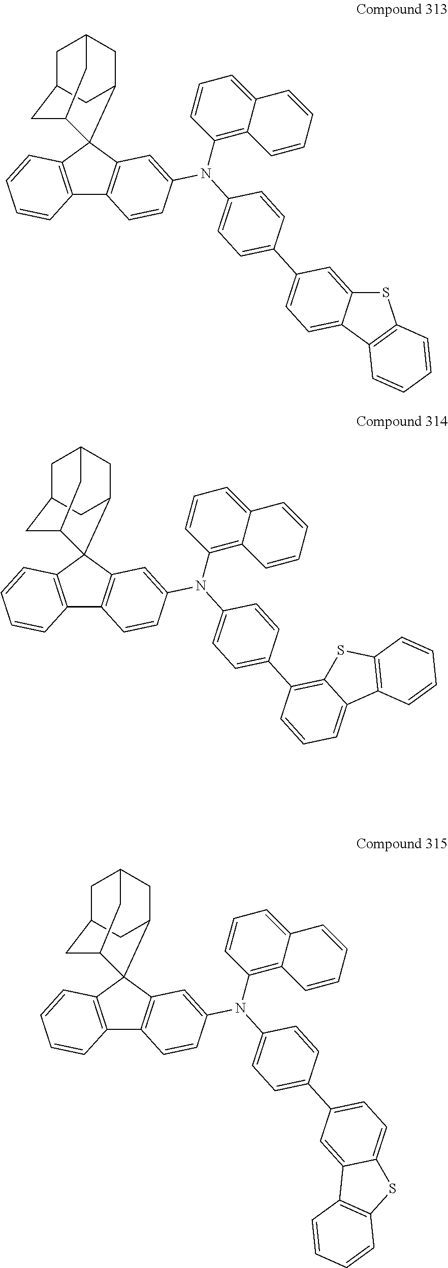
C00107

C00108

C00109
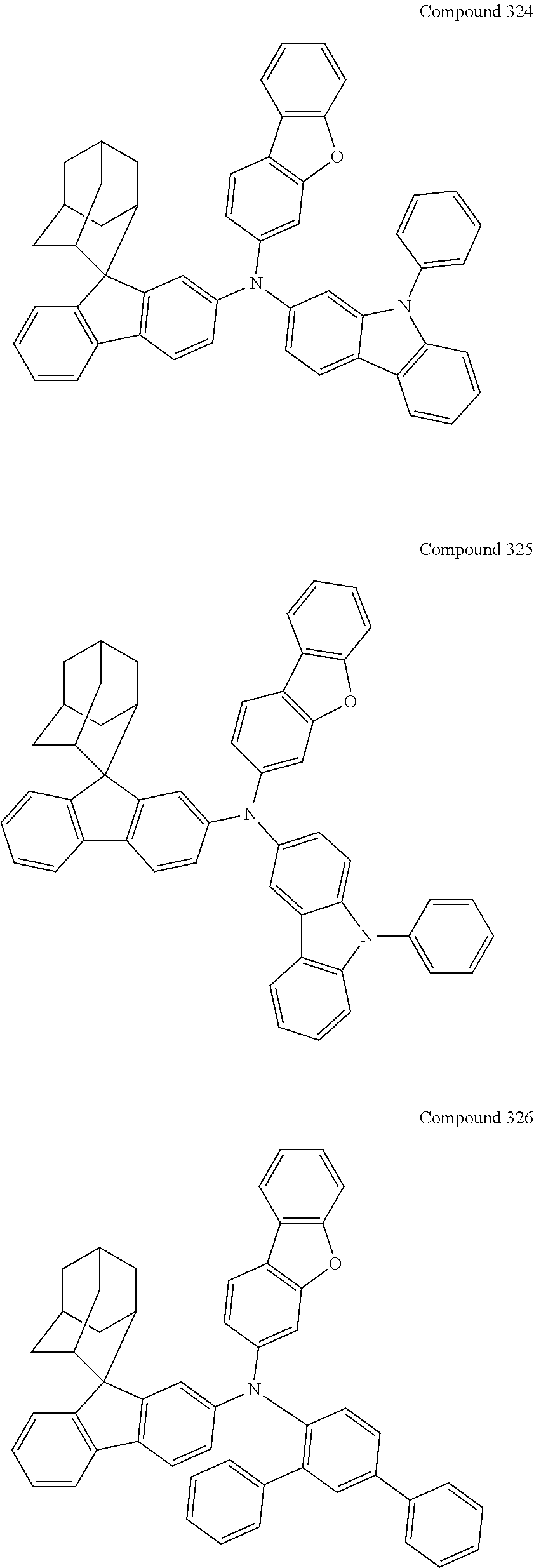
C00110
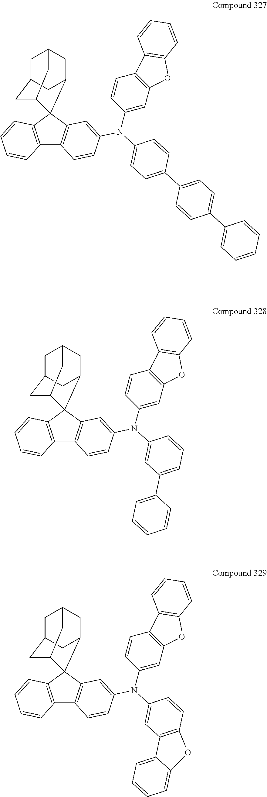
C00111
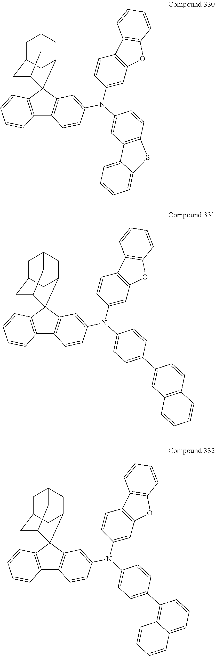
C00112
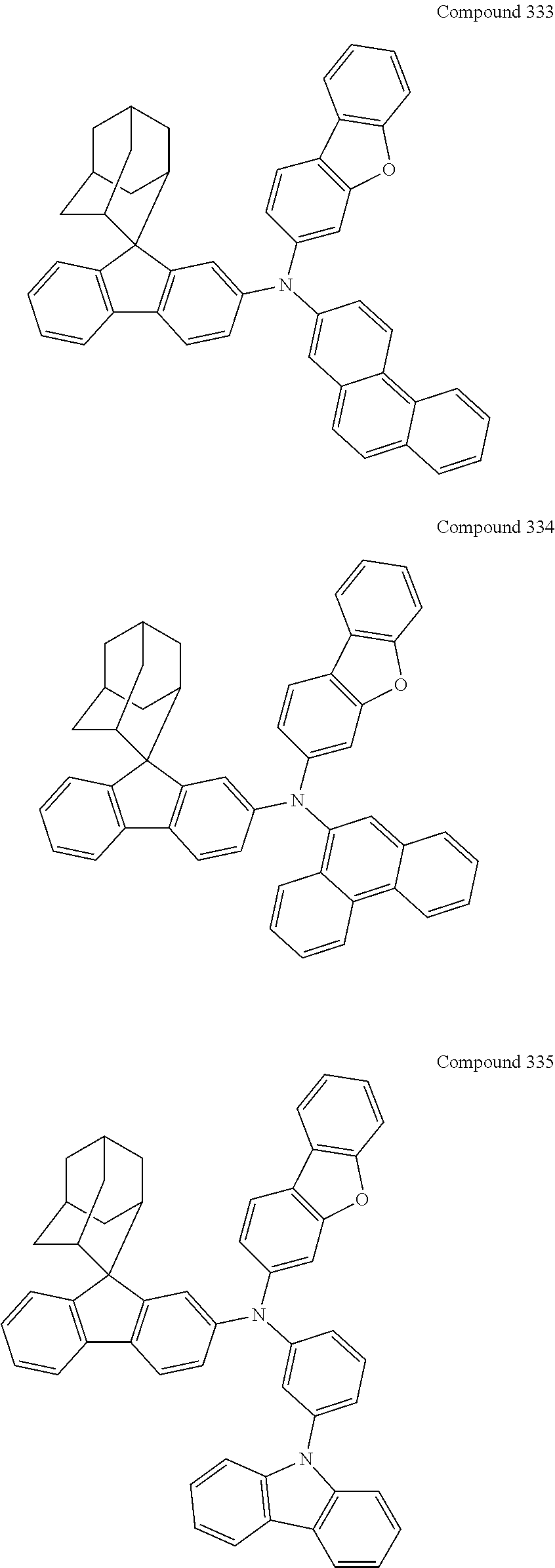
C00113

C00114
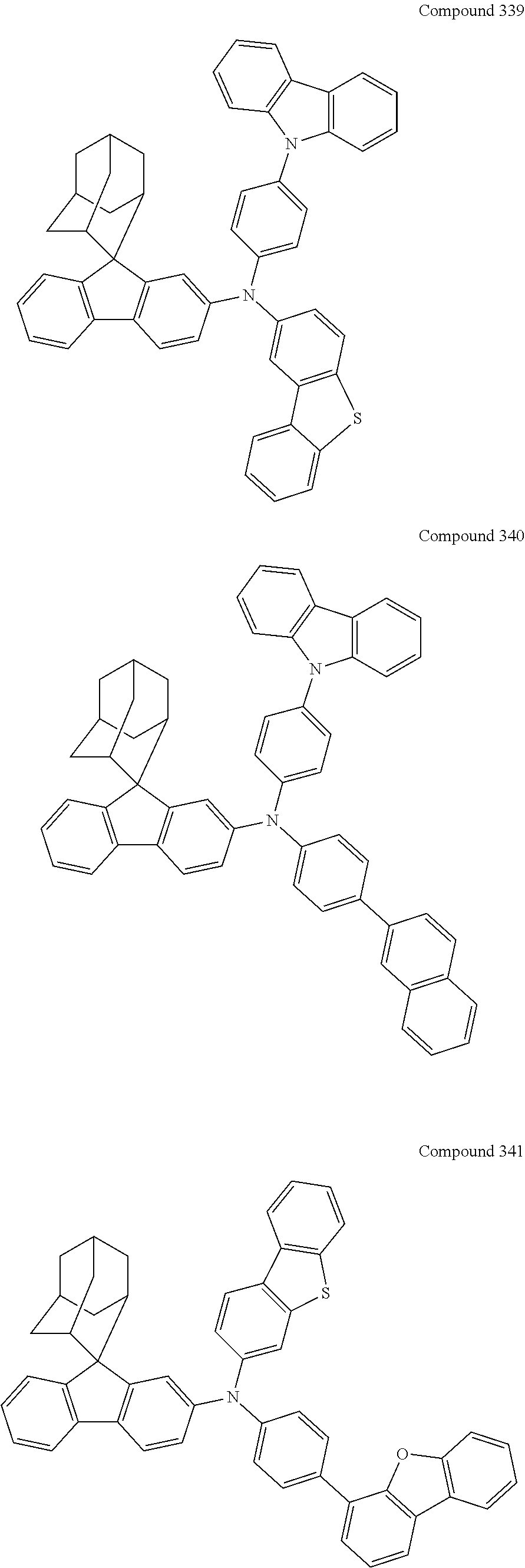
C00115

C00116

C00117

C00118
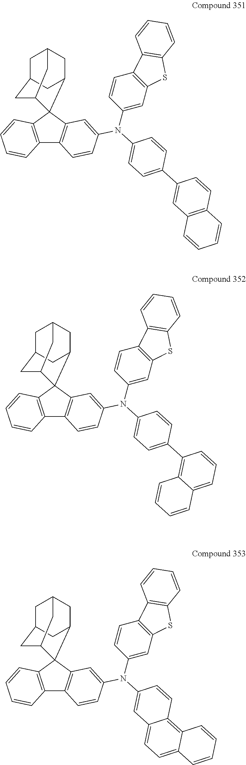
C00119

C00120
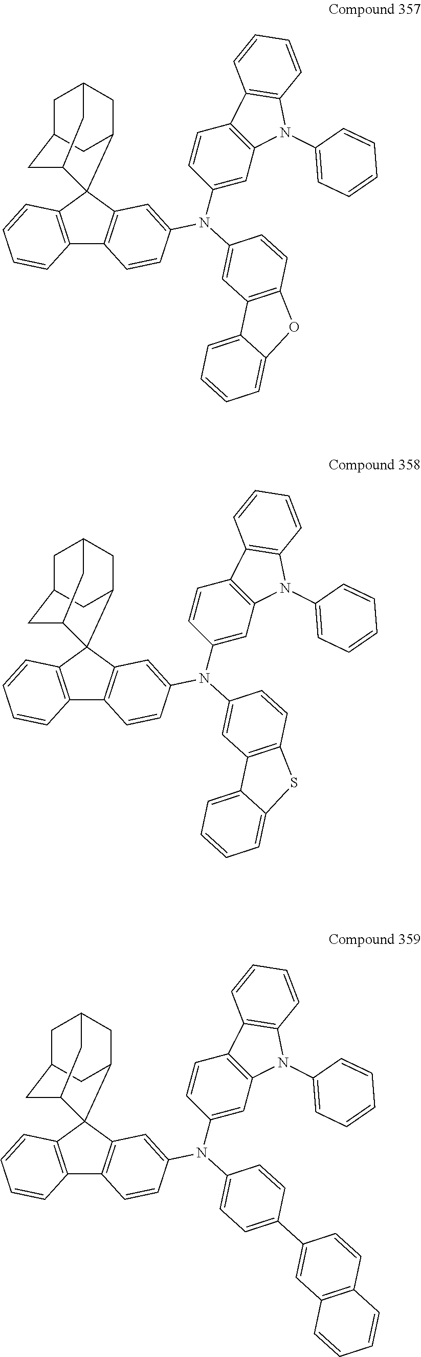
C00121
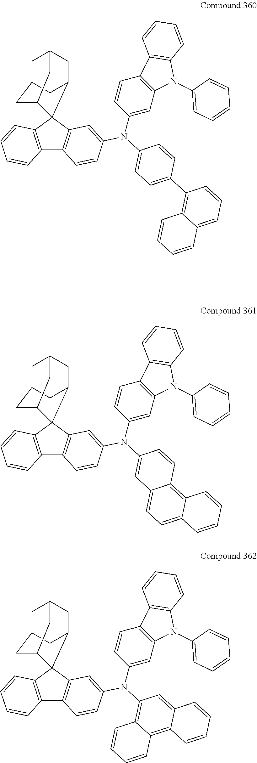
C00122
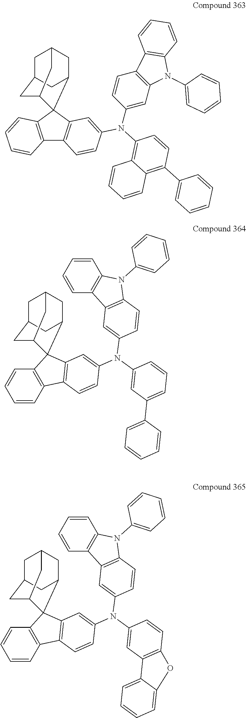
C00123
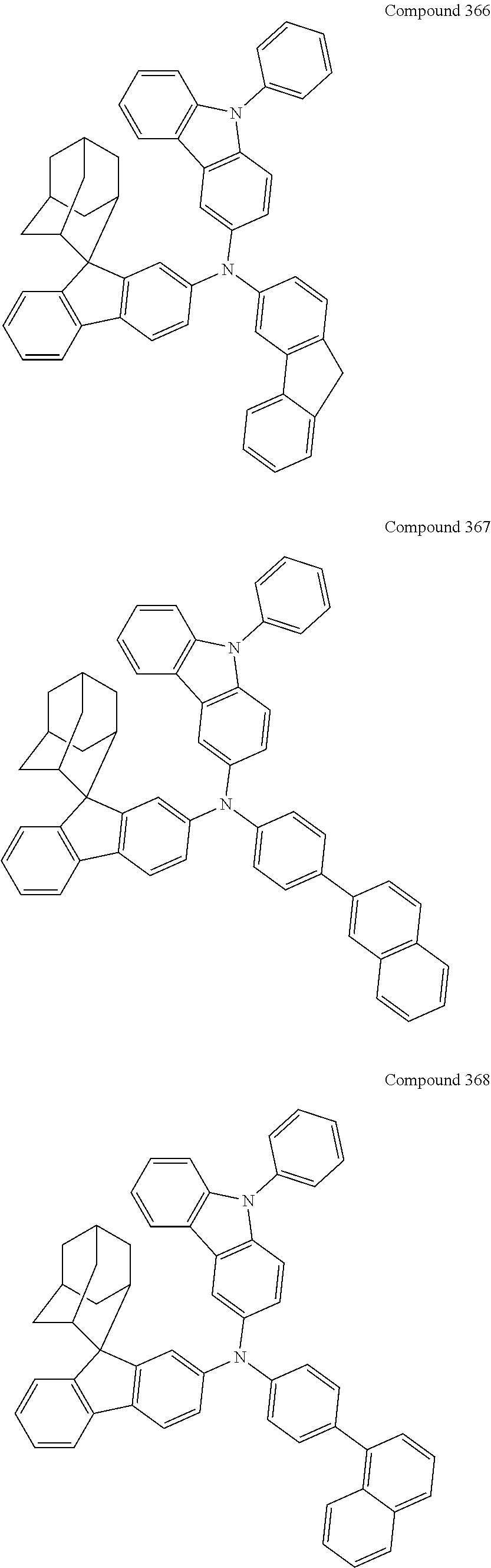
C00124
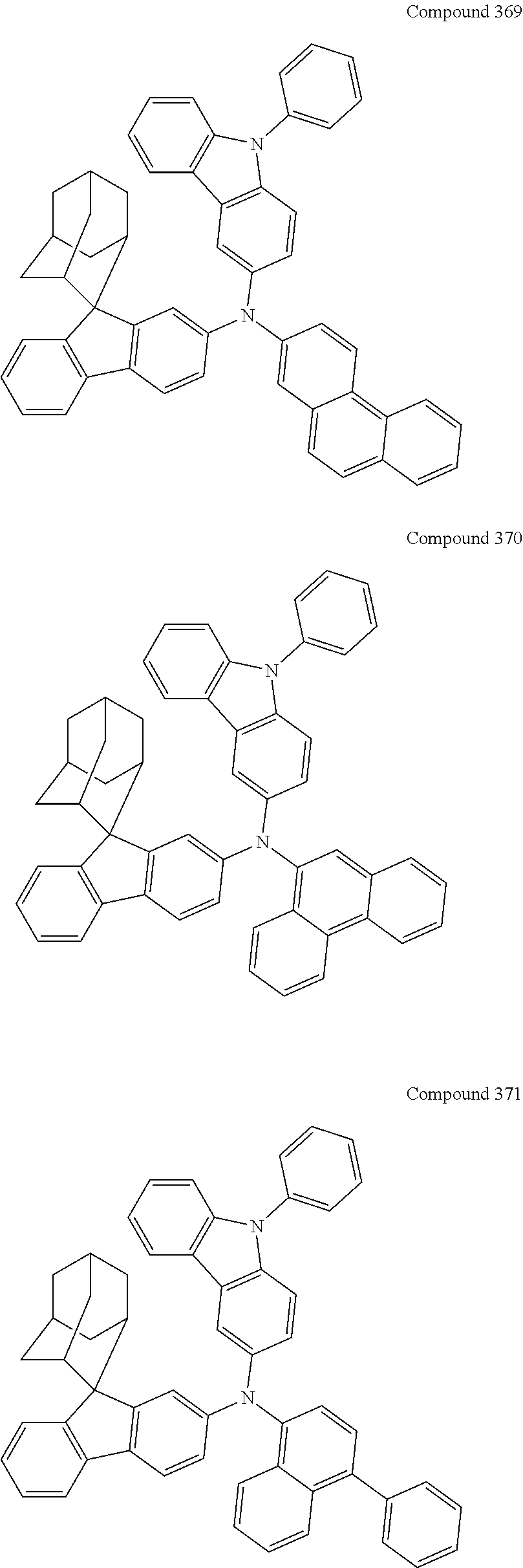
C00125

C00126

C00127
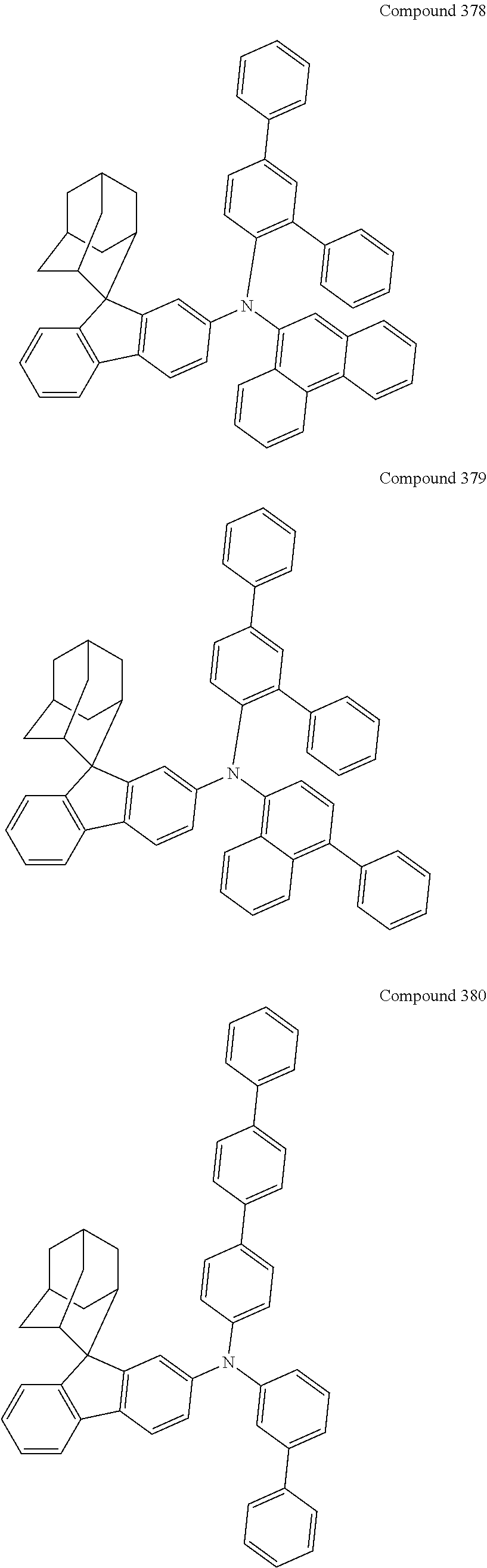
C00128
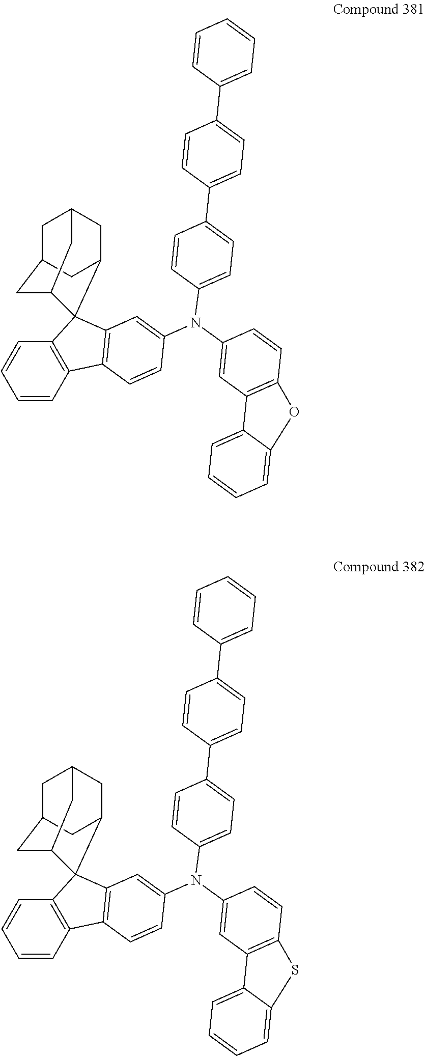
C00129
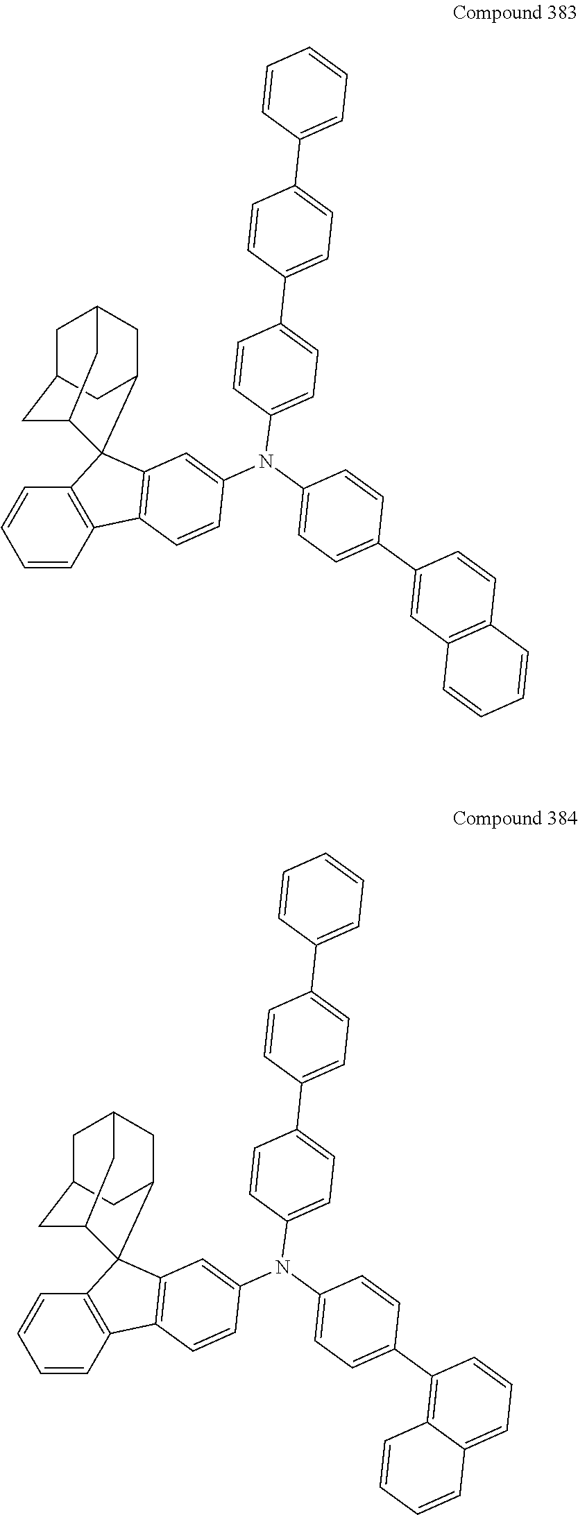
C00130
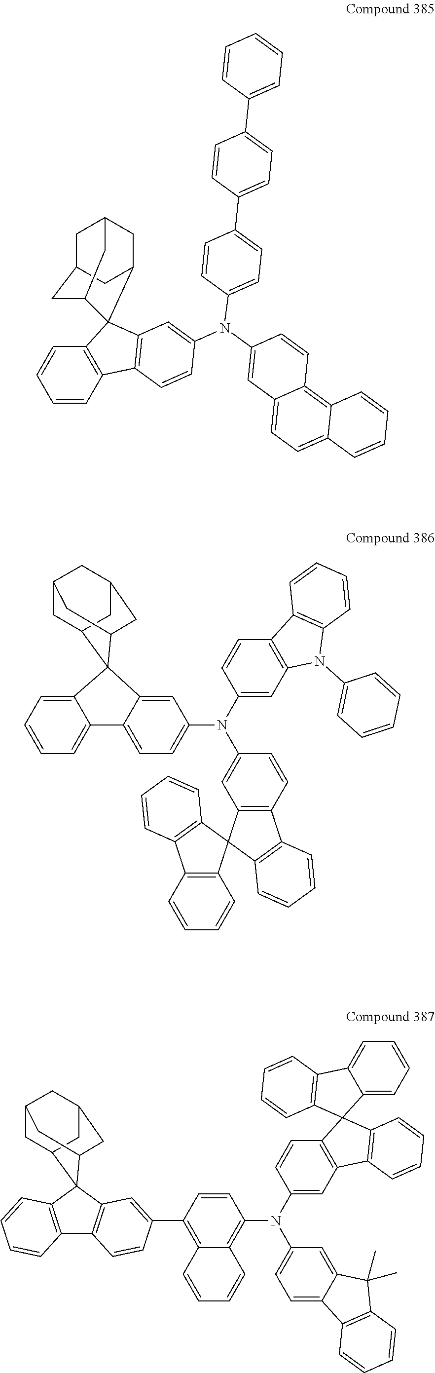
C00131
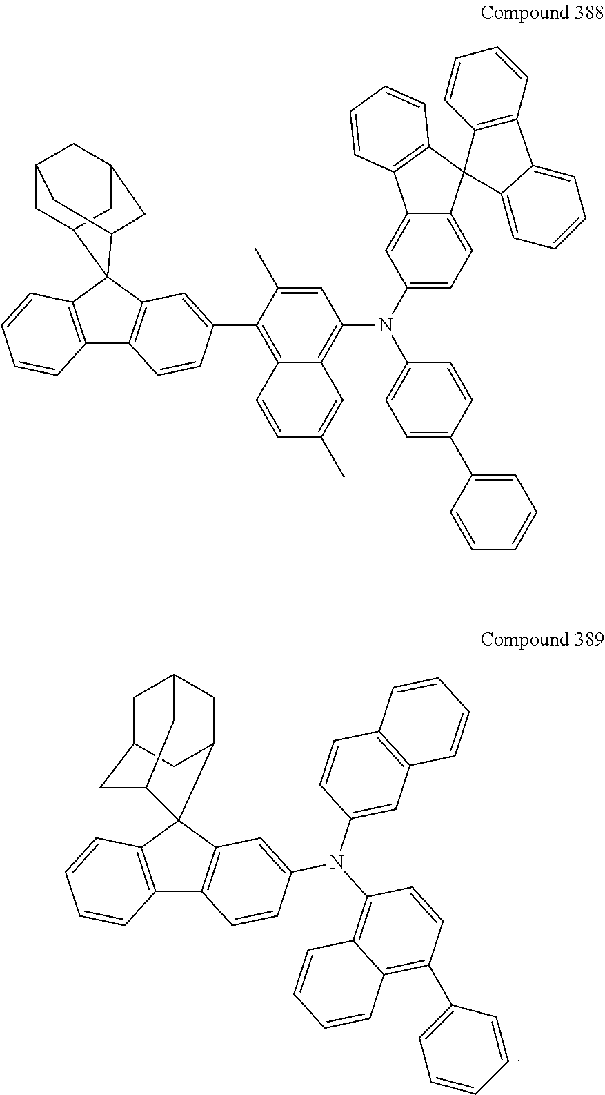
C00132
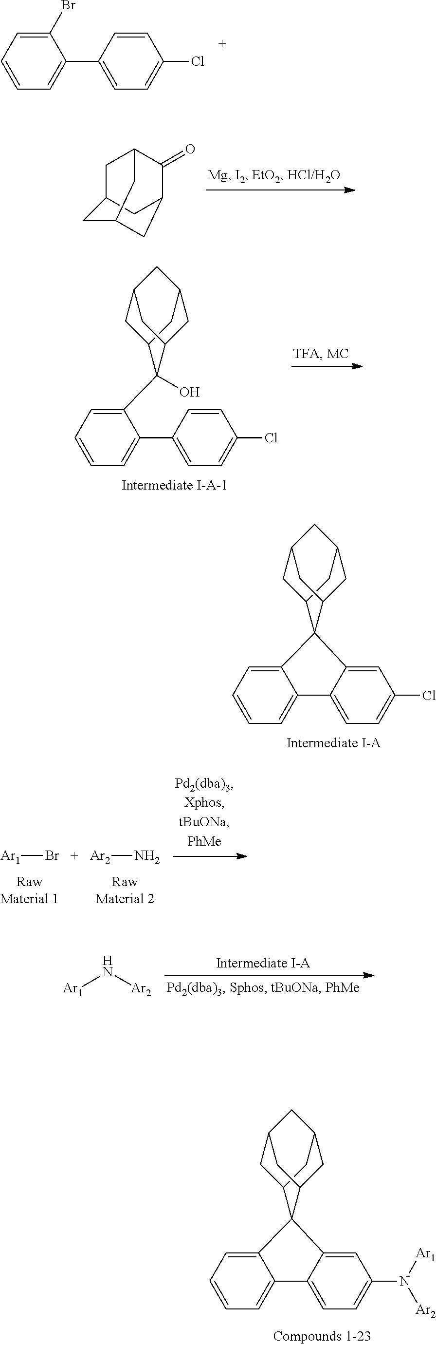
C00133
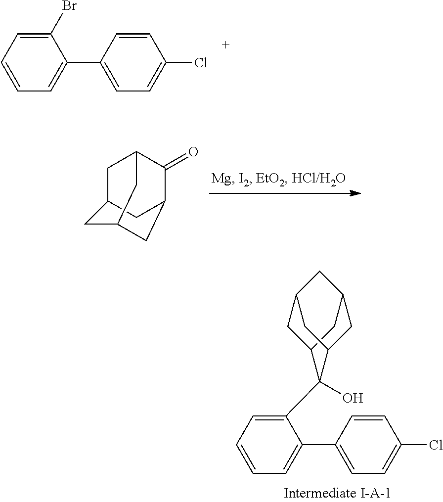
C00134

C00135

C00136
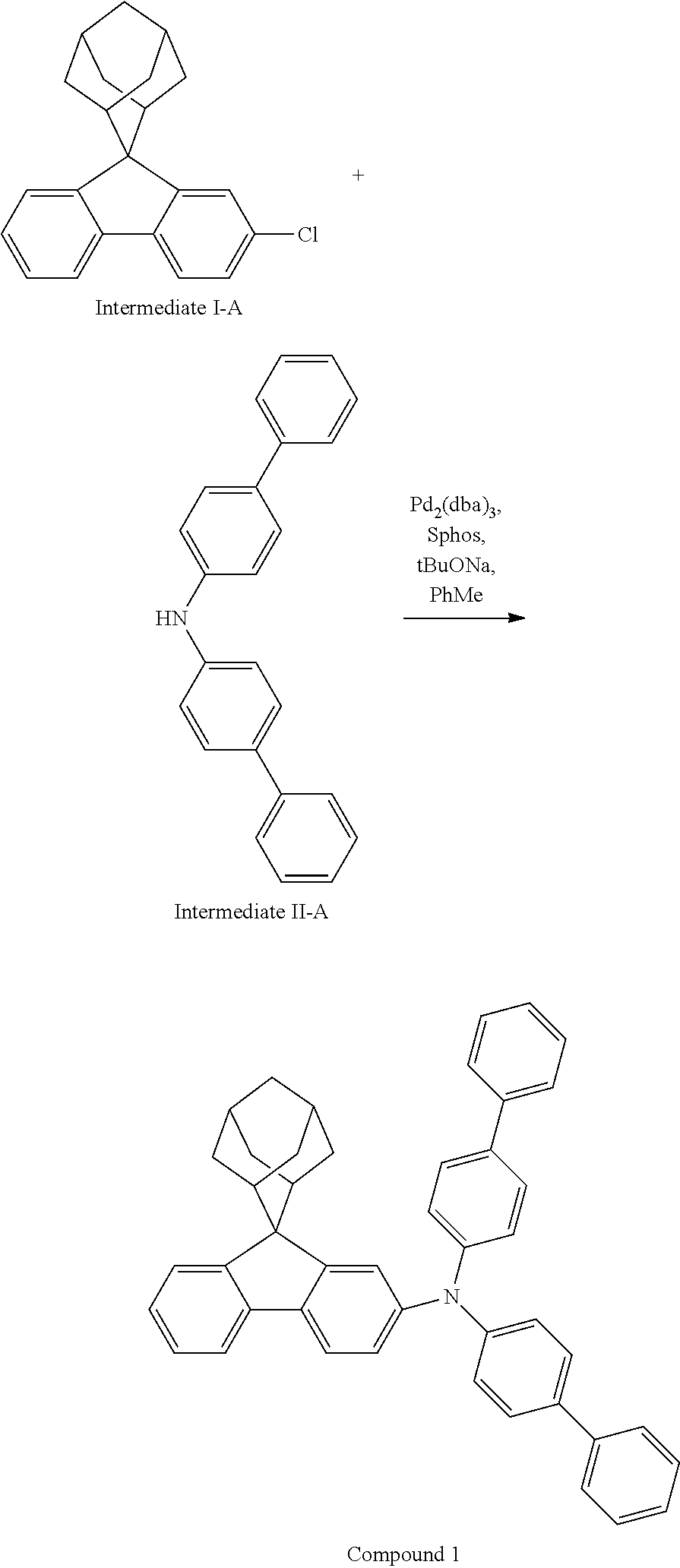
C00137

C00138
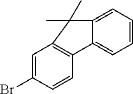
C00139
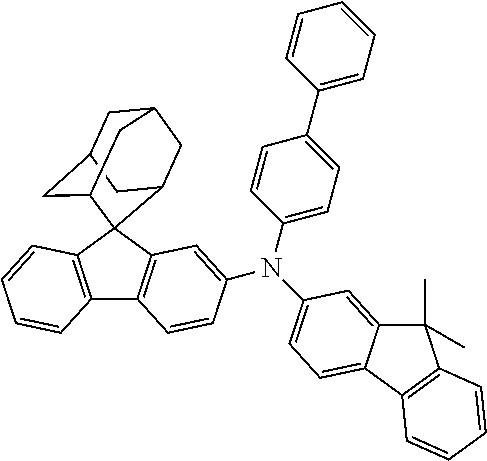
C00140
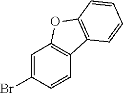
C00141

C00142
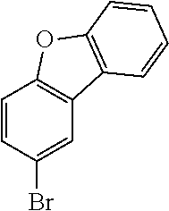
C00143

C00144

C00145

C00146
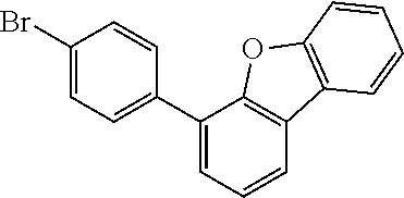
C00147
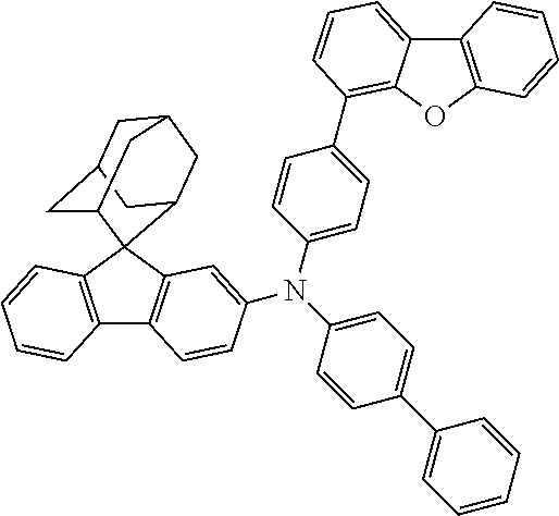
C00148
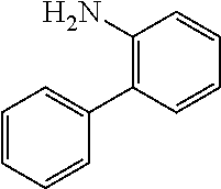
C00149
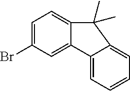
C00150
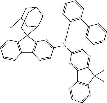
C00151

C00152

C00153
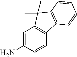
C00154

C00155
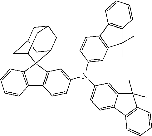
C00156
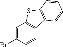
C00157
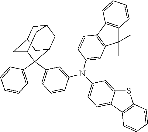
C00158
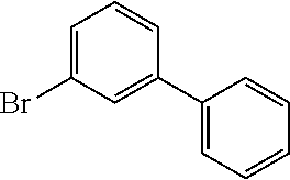
C00159
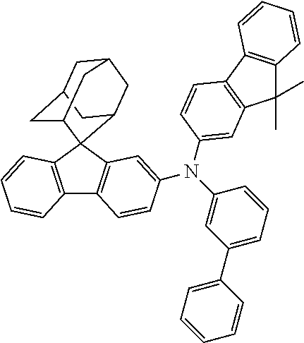
C00160

C00161

C00162
C00163
C00164

C00165

C00166
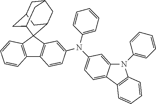
C00167
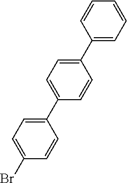
C00168
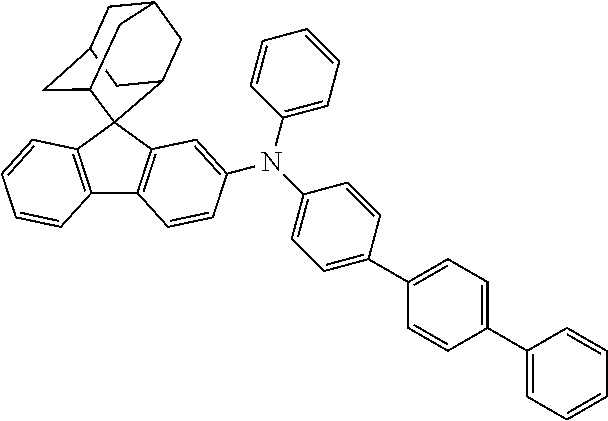
C00169

C00170
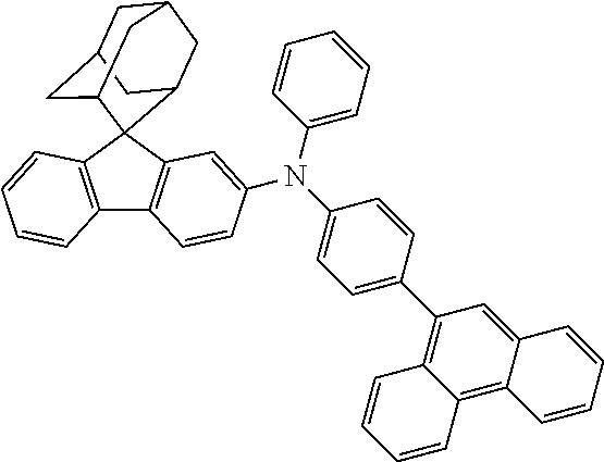
C00171
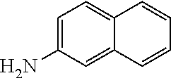
C00172
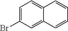
C00173

C00174

C00175
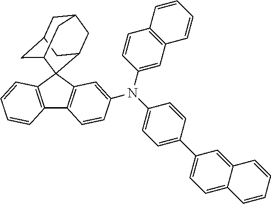
C00176

C00177
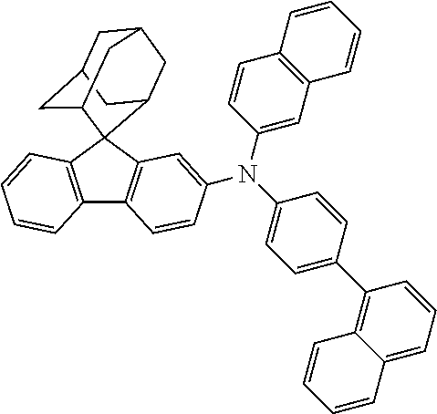
C00178

C00179
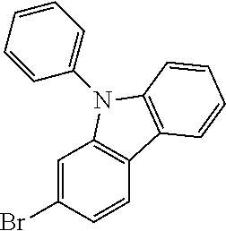
C00180

C00181
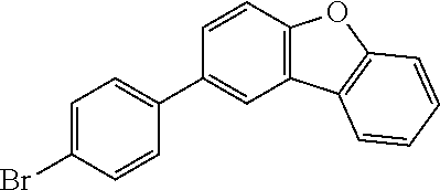
C00182
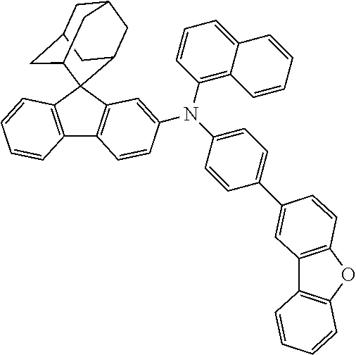
C00183
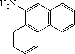
C00184

C00185
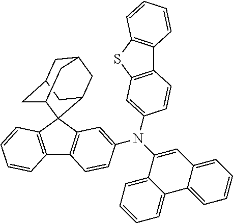
C00186
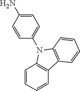
C00187

C00188
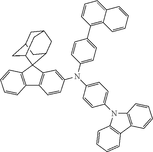
C00189
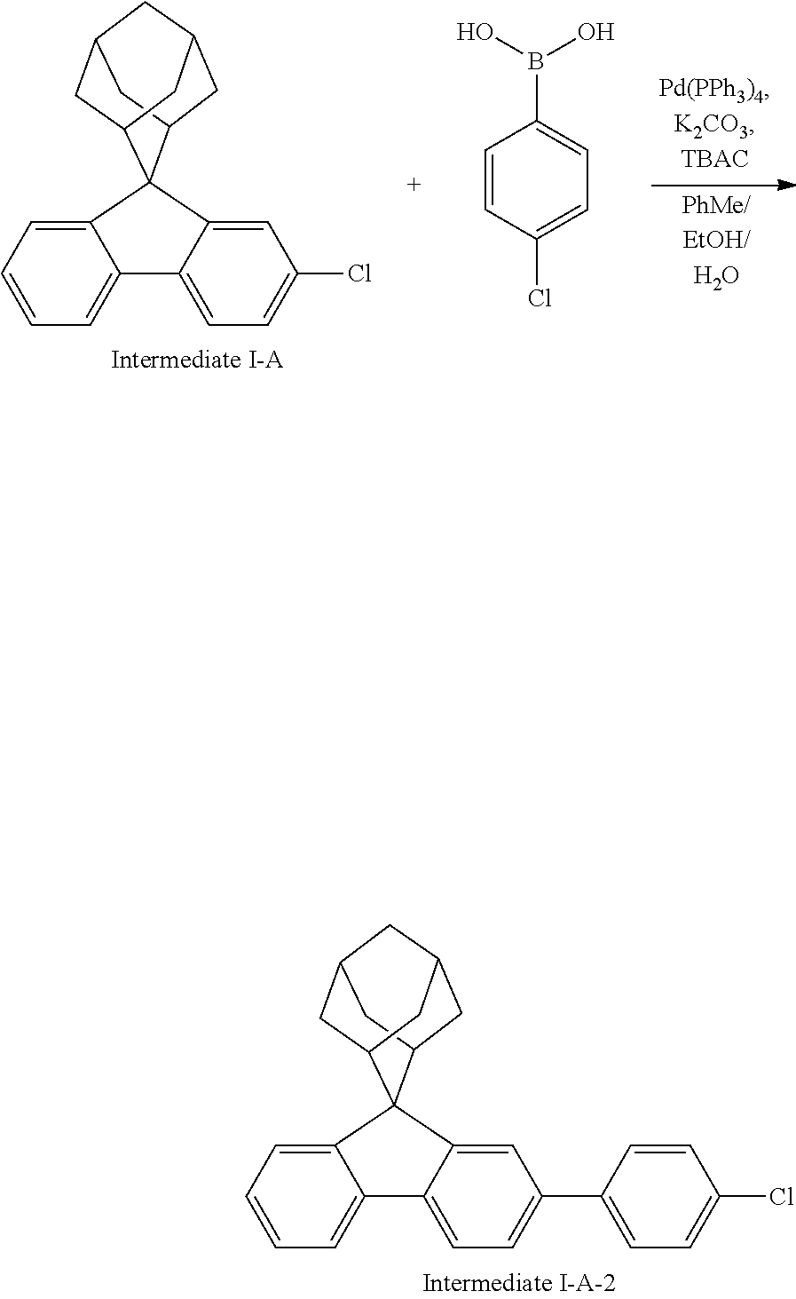
C00190
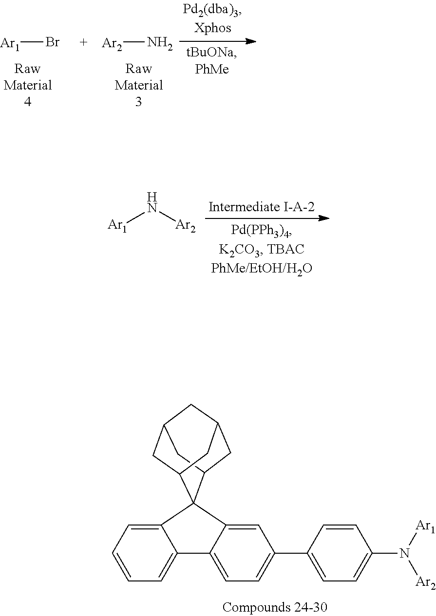
C00191
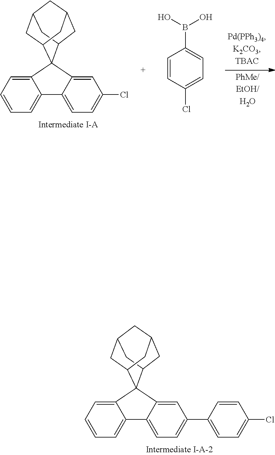
C00192

C00193

C00194
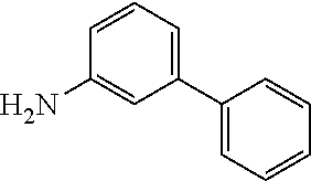
C00195
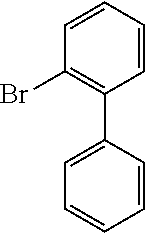
C00196

C00197

C00198
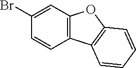
C00199
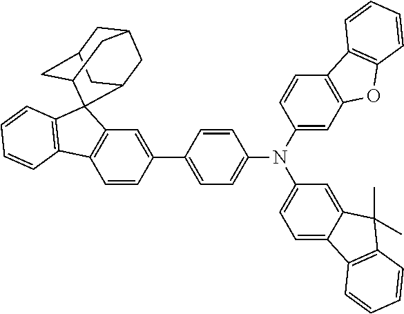
C00200
C00201
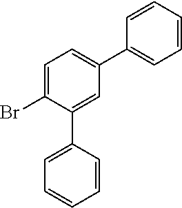
C00202
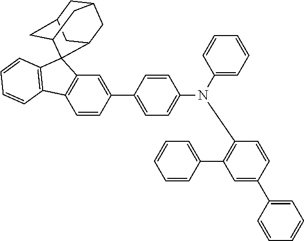
C00203

C00204
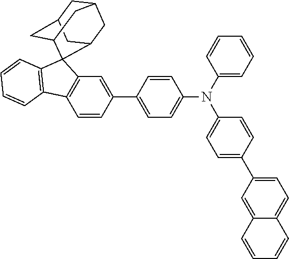
C00205
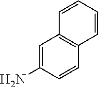
C00206
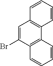
C00207

C00208
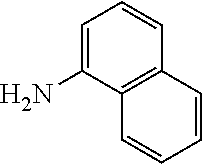
C00209
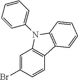
C00210
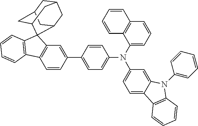
C00211
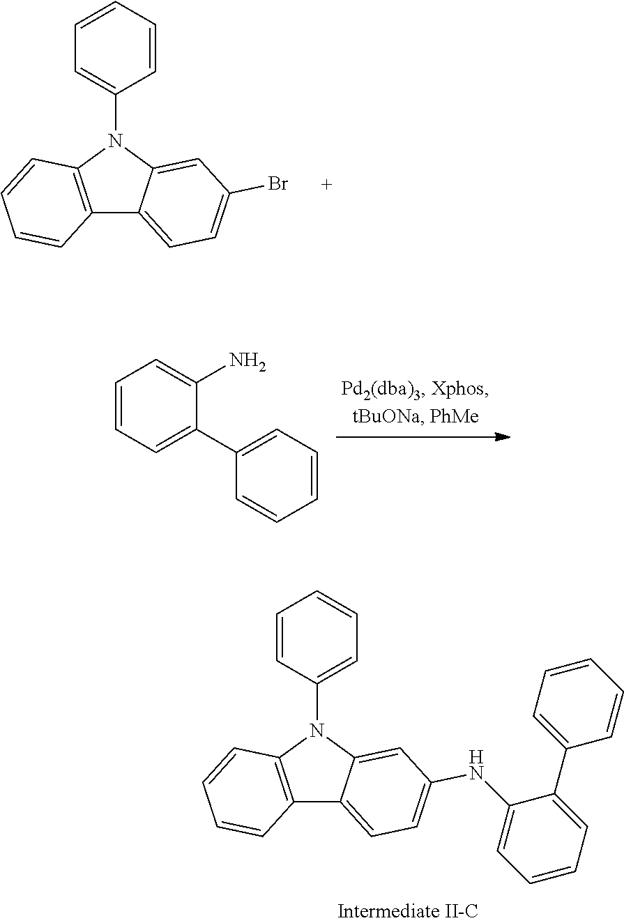
C00212

C00213
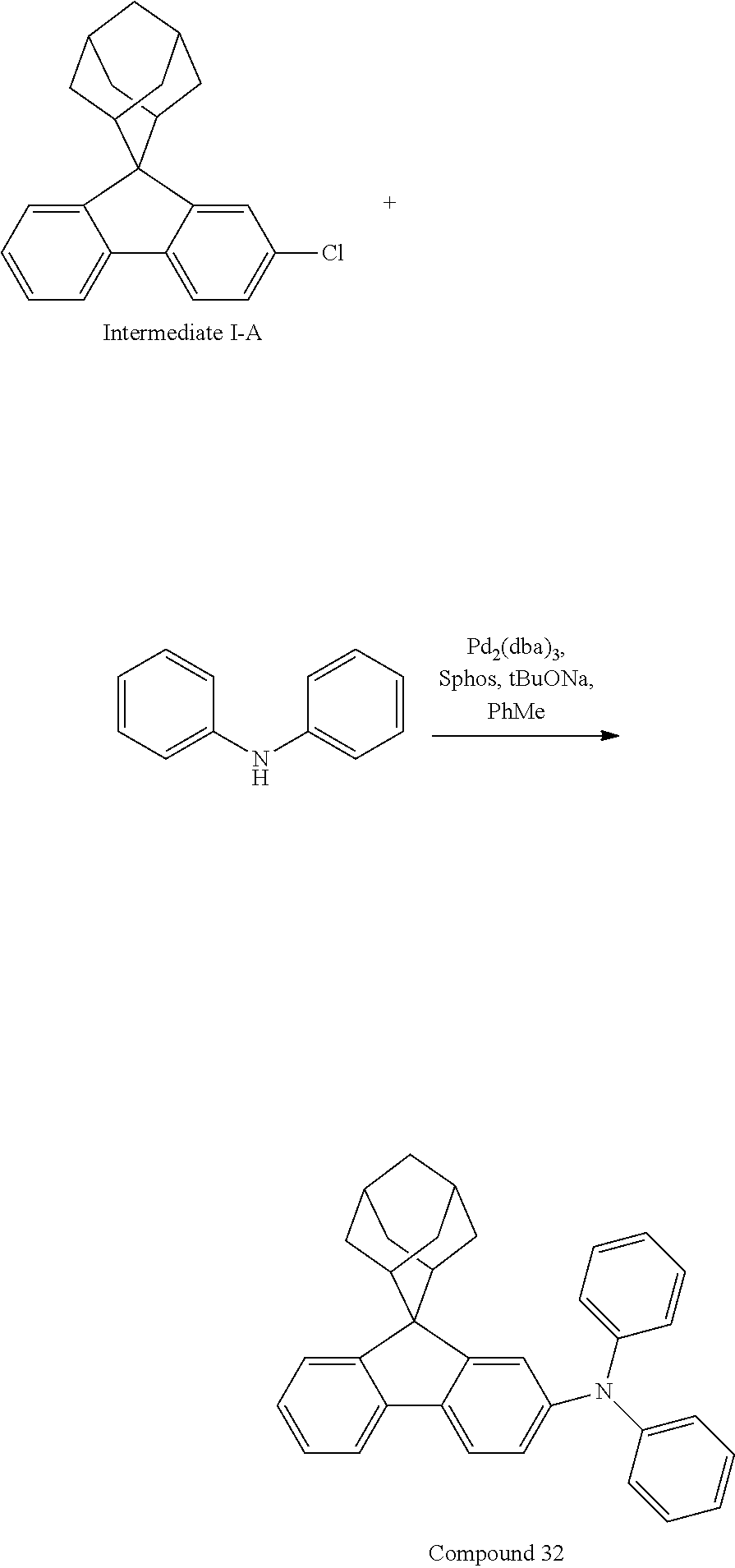
C00214
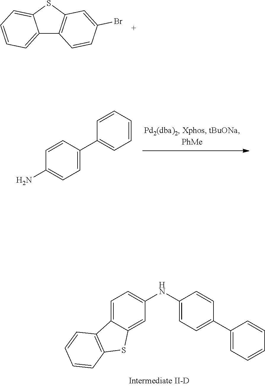
C00215
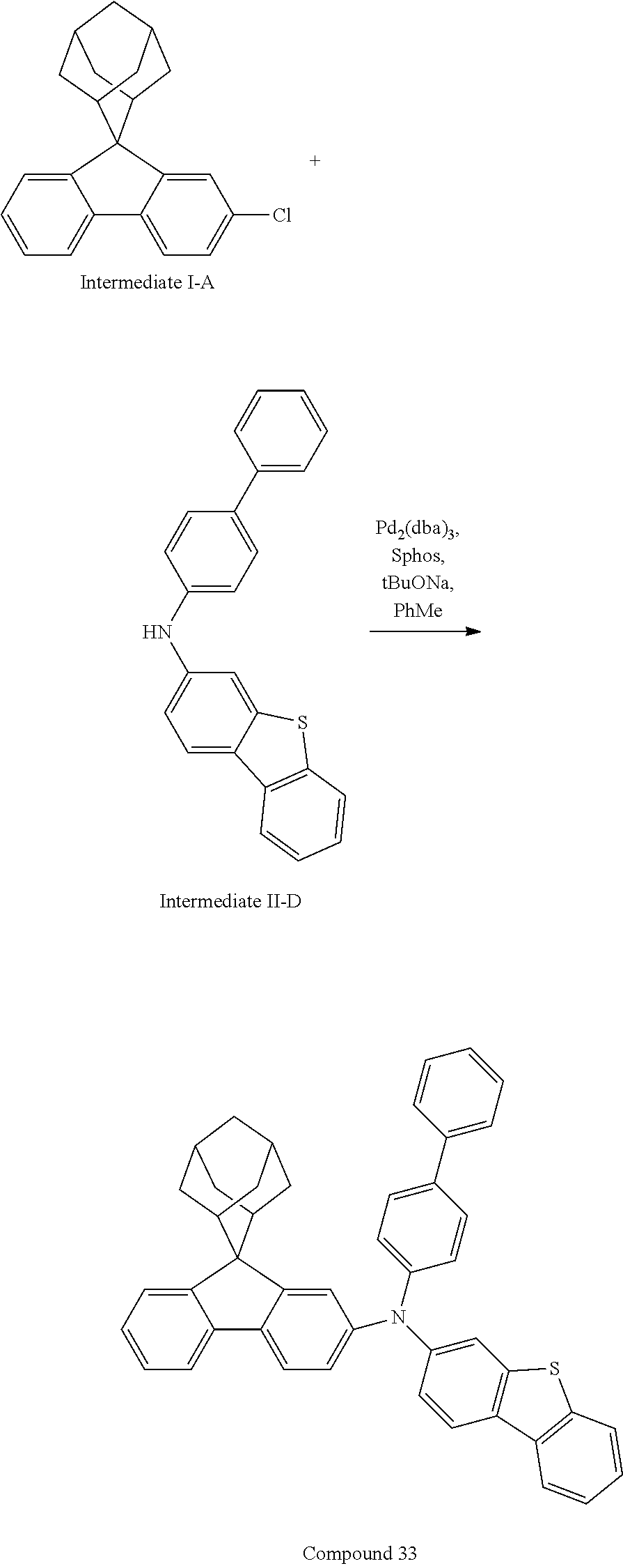
C00216
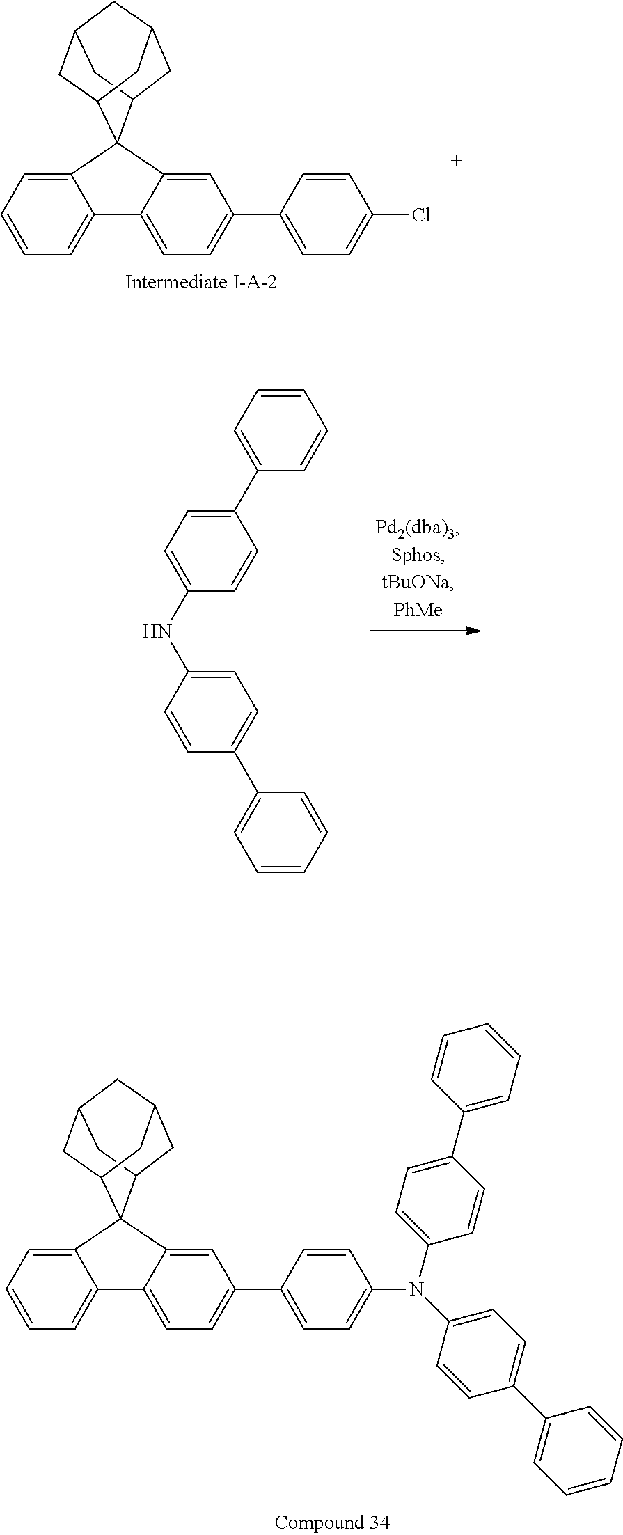
C00217

C00218
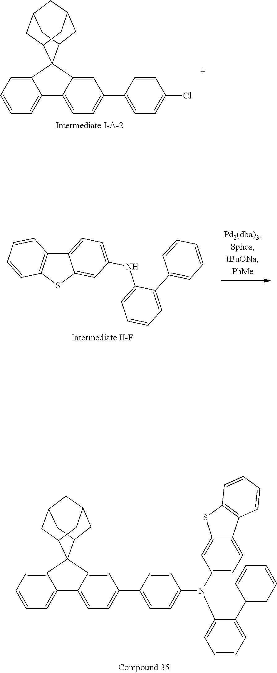
C00219
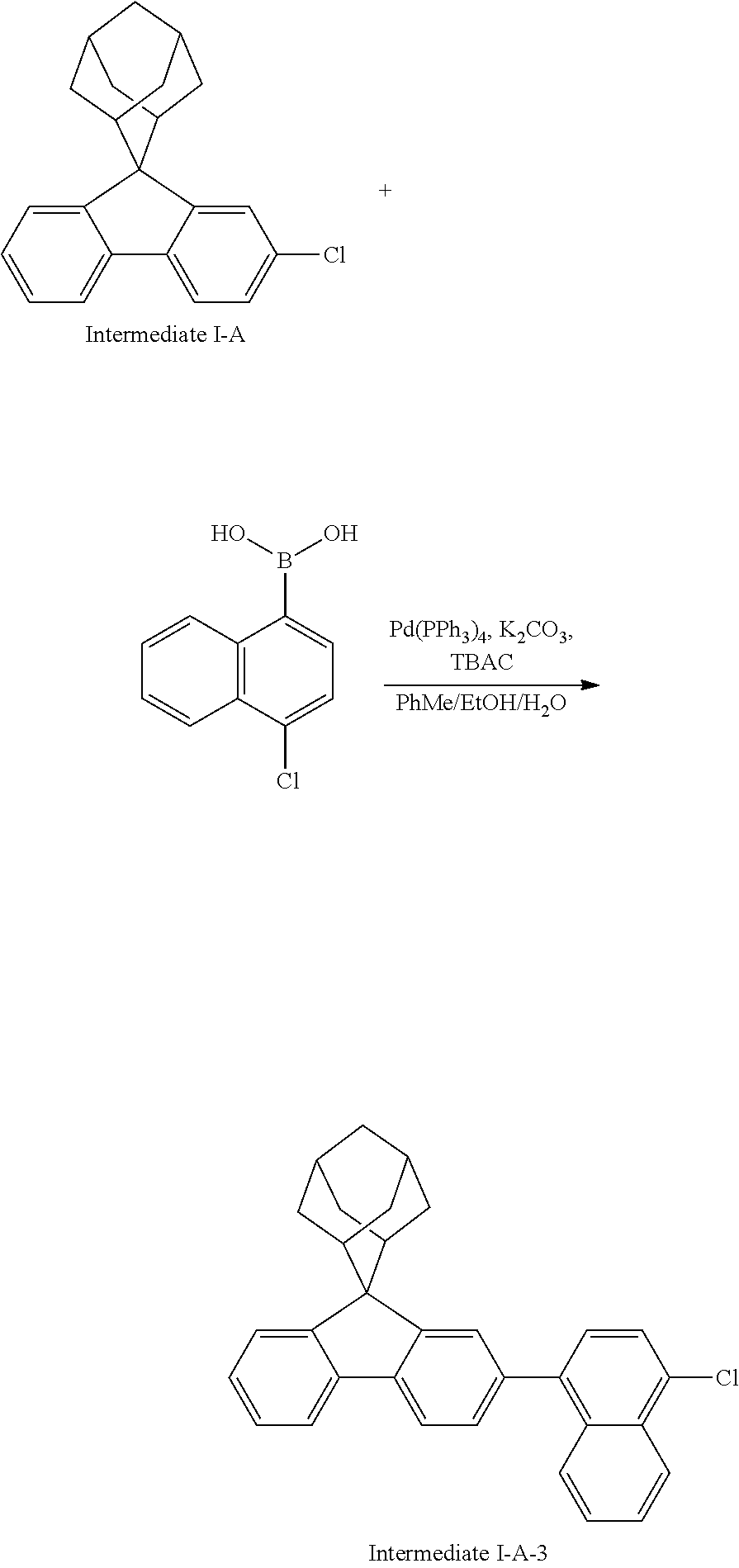
C00220
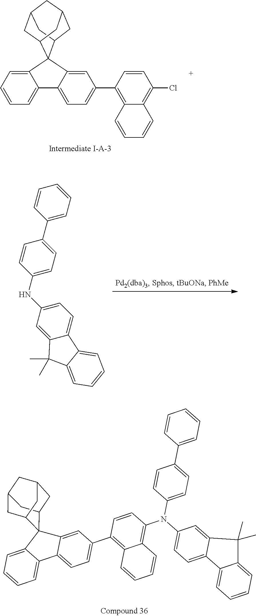
C00221

C00222
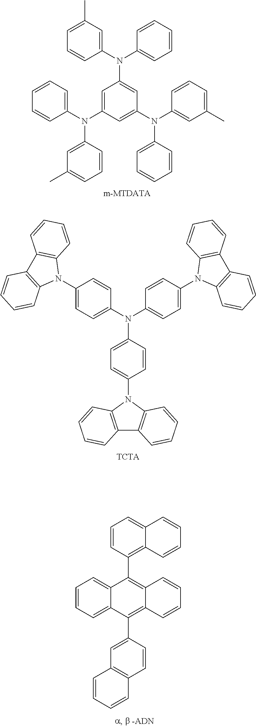
C00223
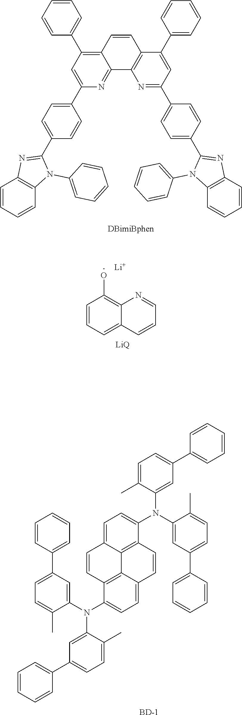
C00224

C00225
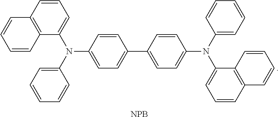
C00226
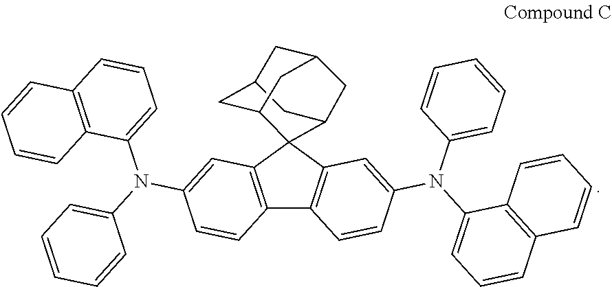
C00227
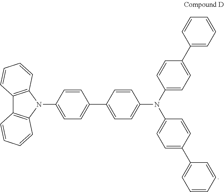
C00228

C00229

C00230
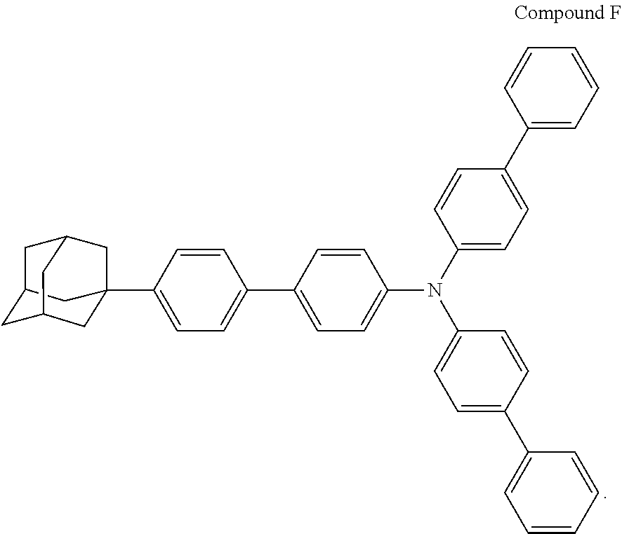
C00231

C00232

C00233
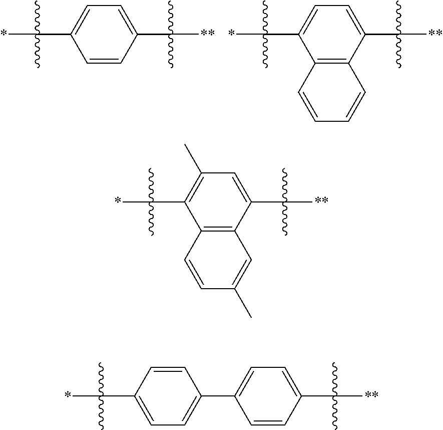
C00234
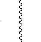
C00235
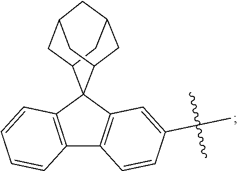
C00236
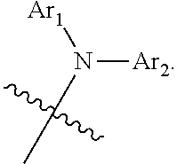
C00237
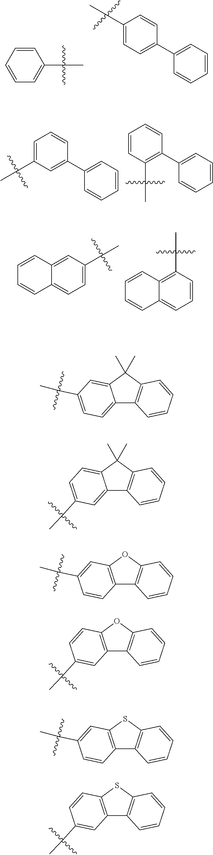
C00238

C00239

C00240
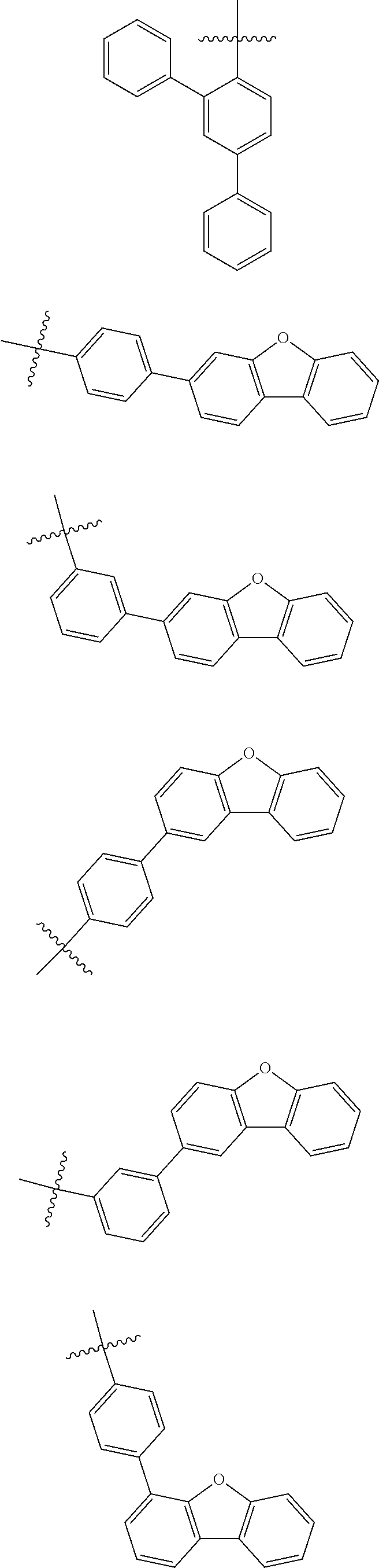
C00241

C00242
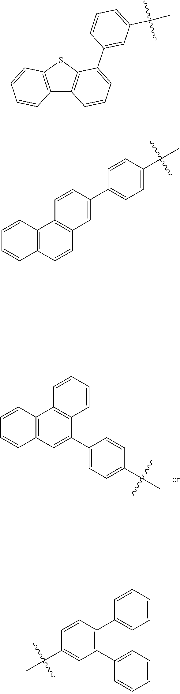
C00243
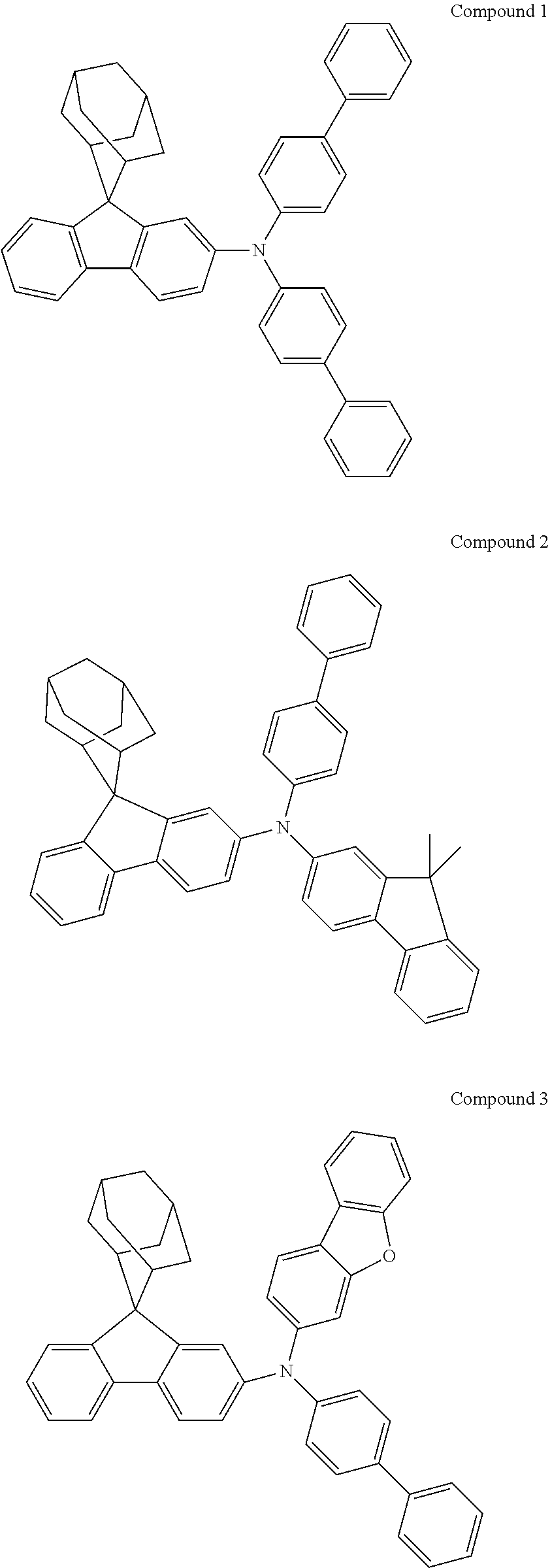
C00244
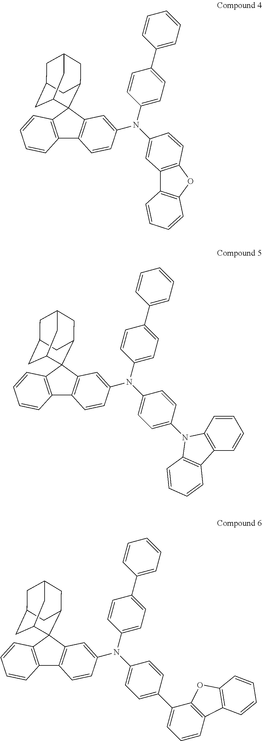
C00245
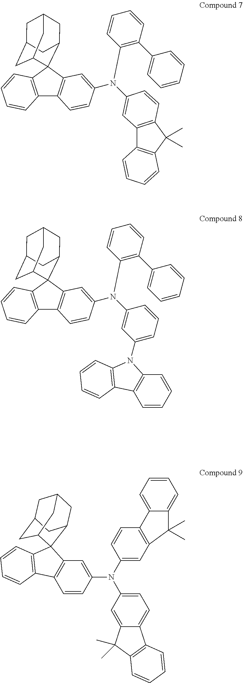
C00246
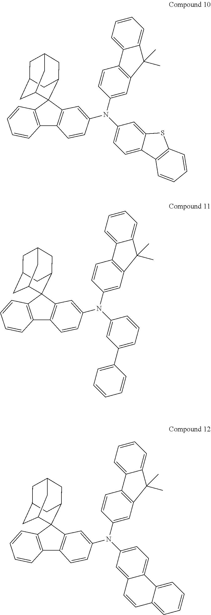
C00247
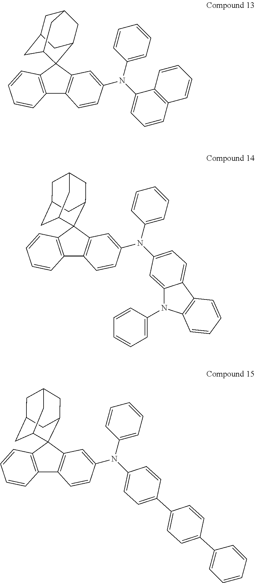
C00248
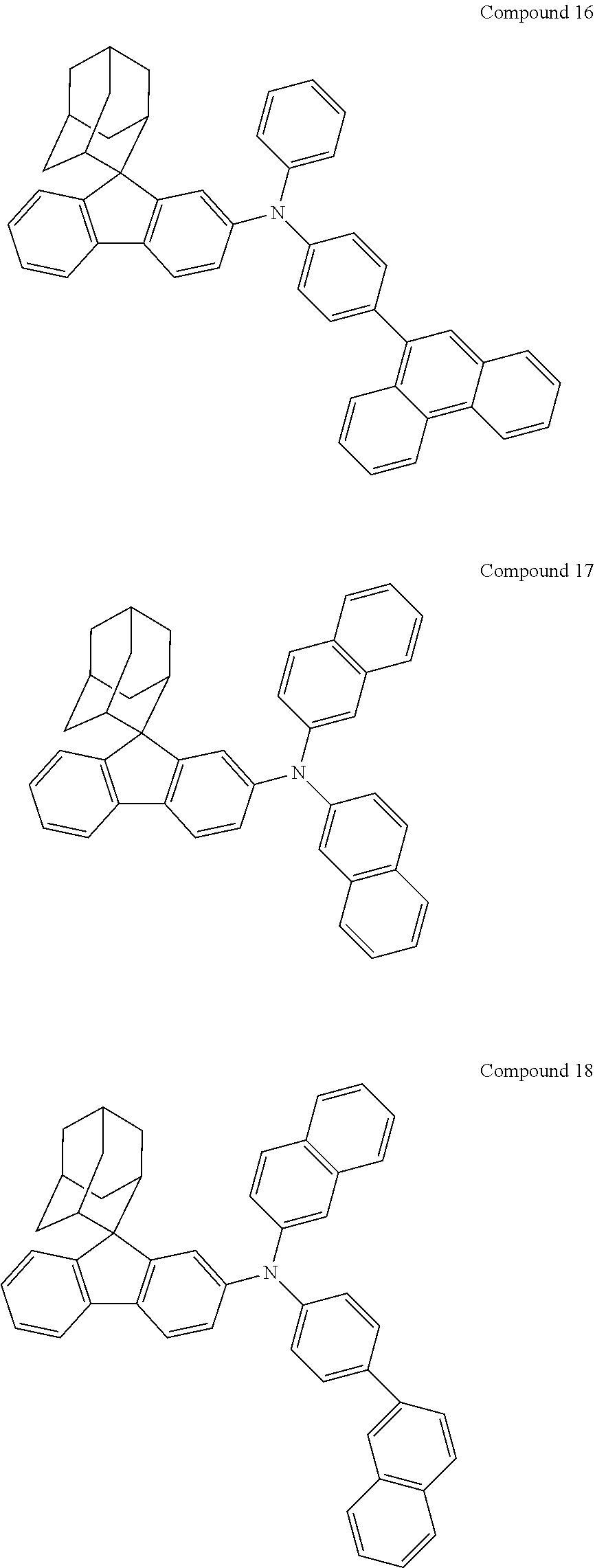
C00249
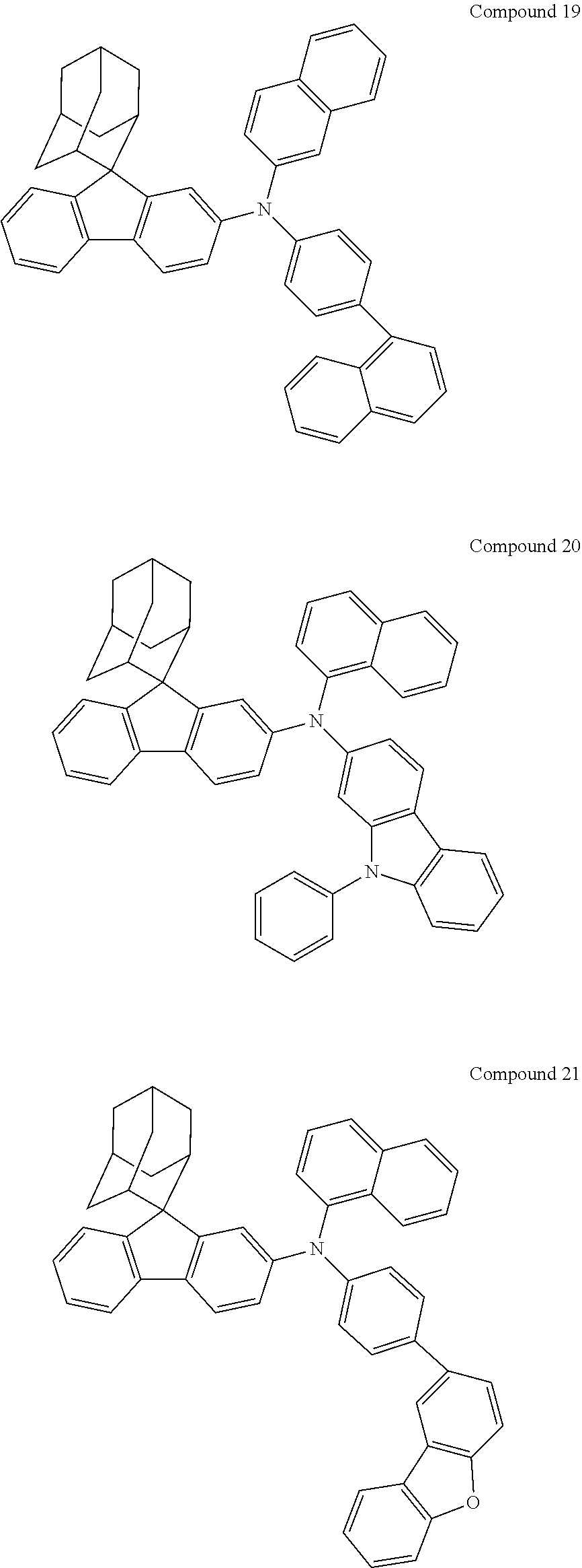
C00250
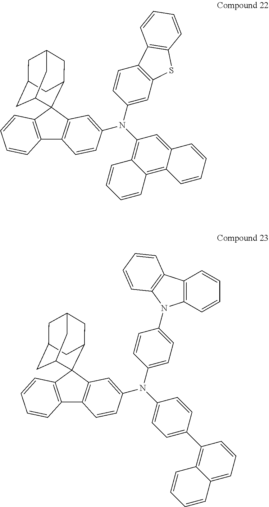
C00251

C00252

C00253

C00254
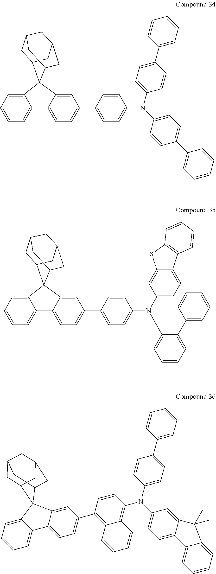
C00255
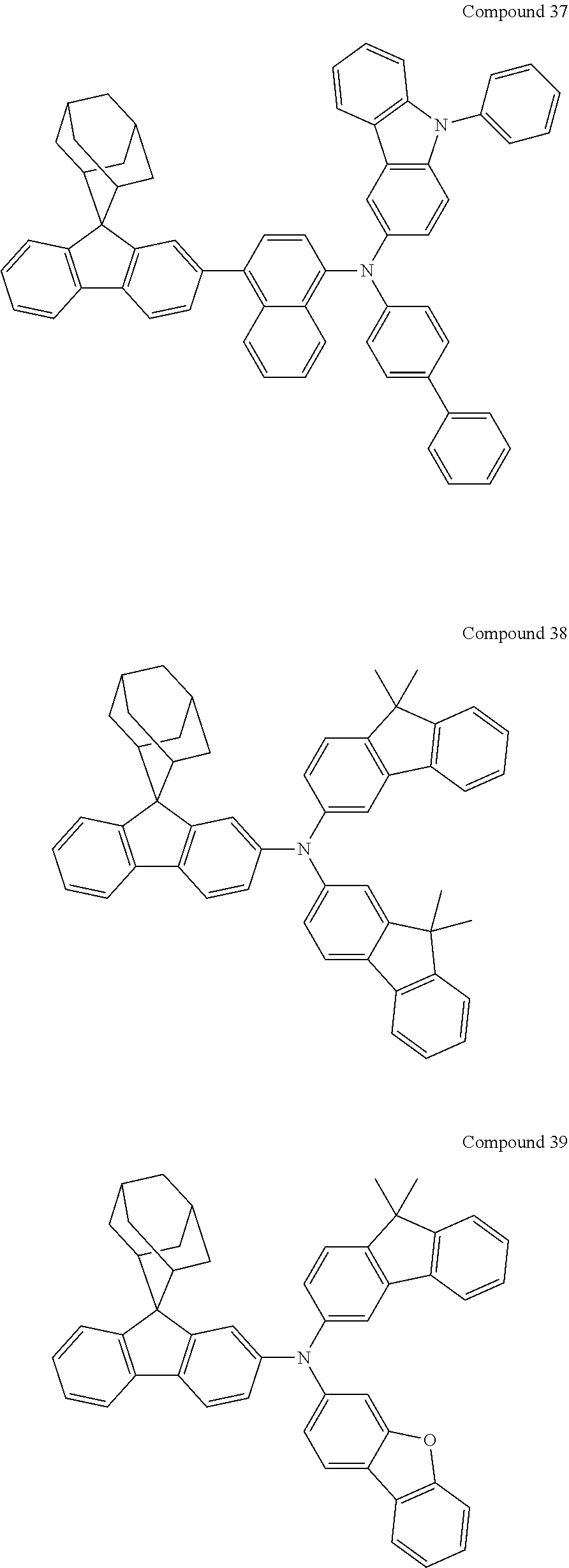
C00256

C00257
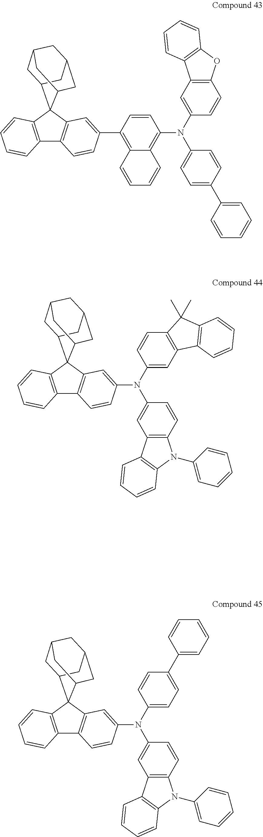
C00258
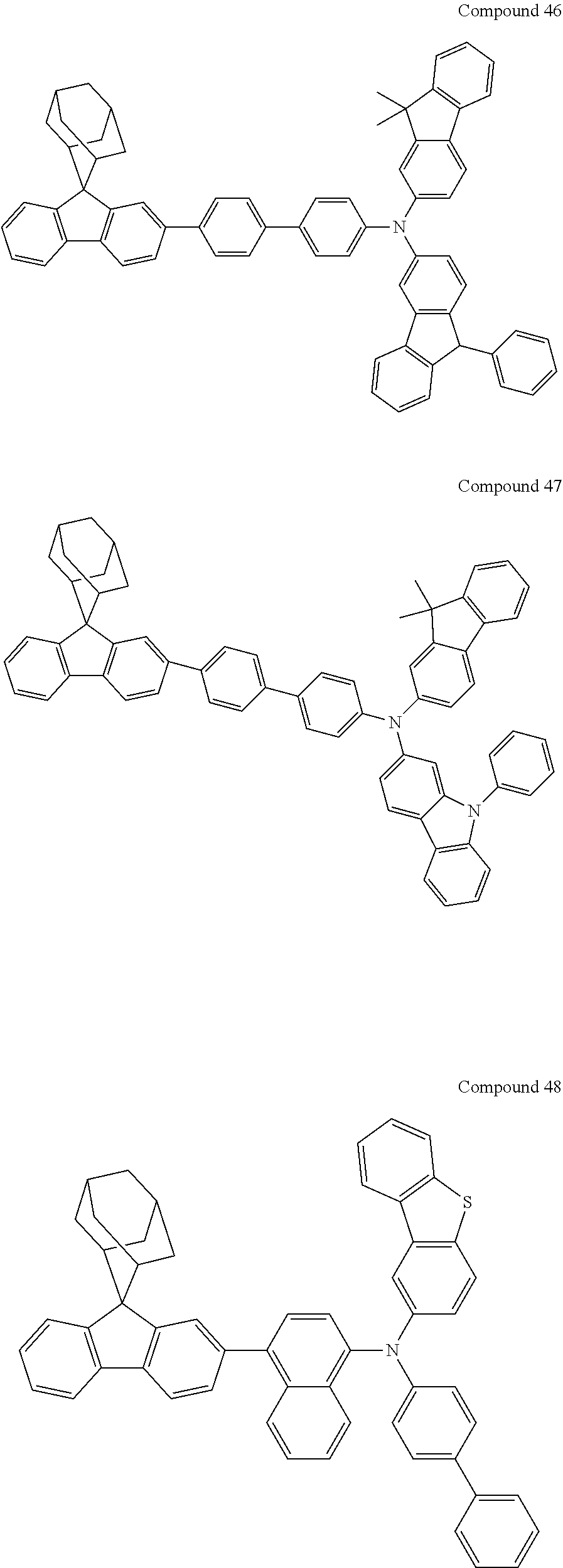
C00259
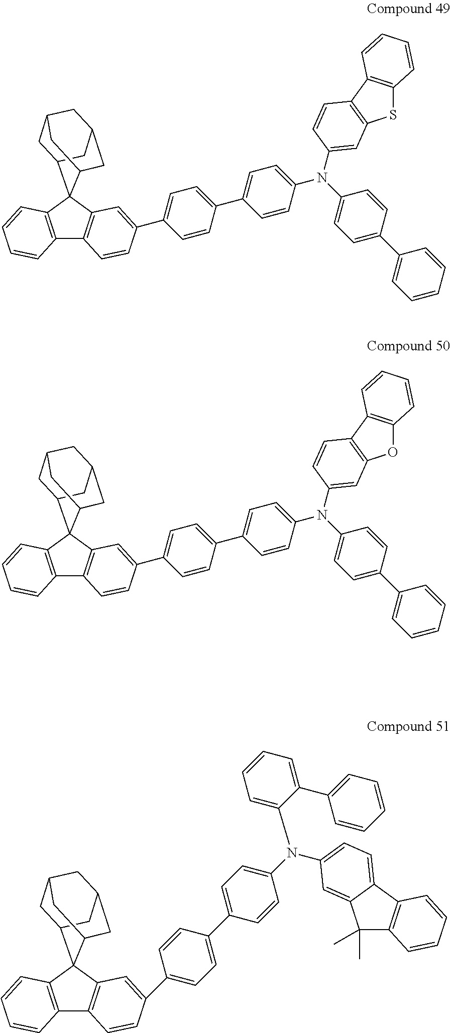
C00260
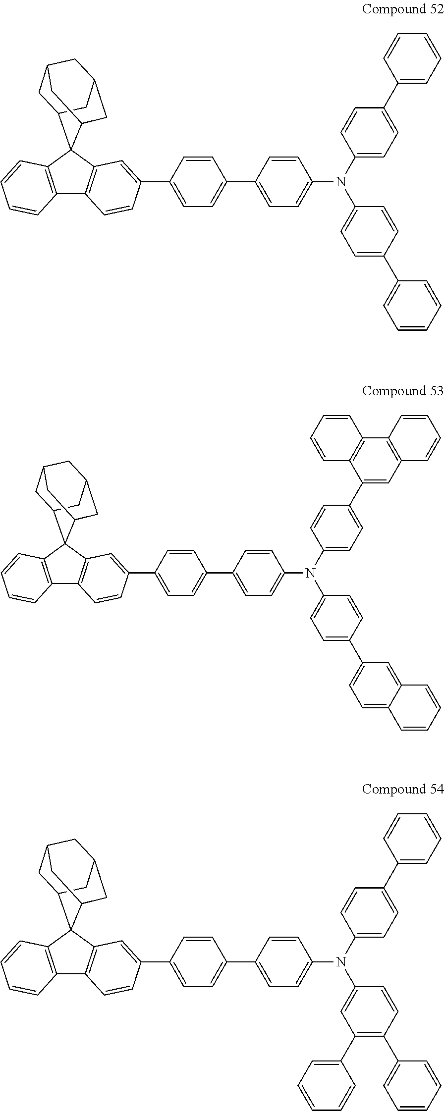
C00261
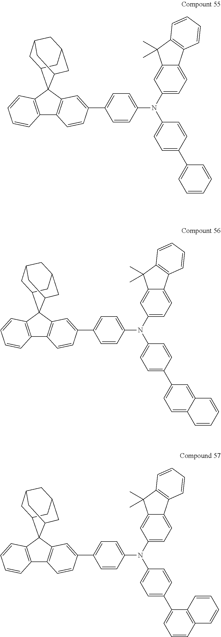
C00262
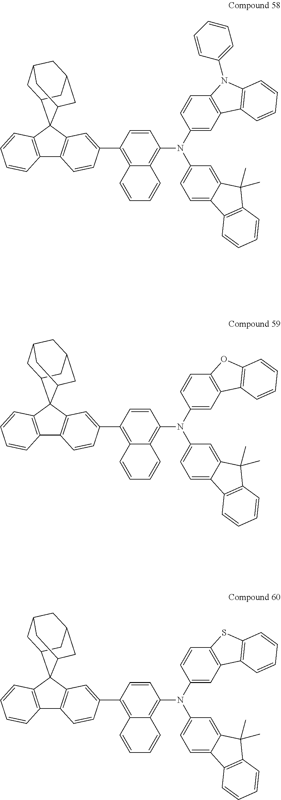
C00263
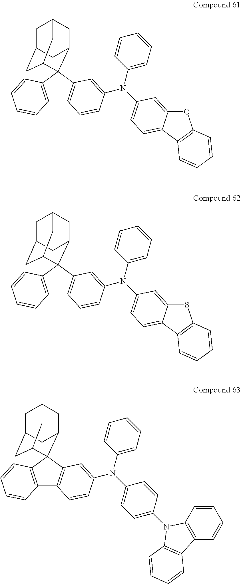
C00264
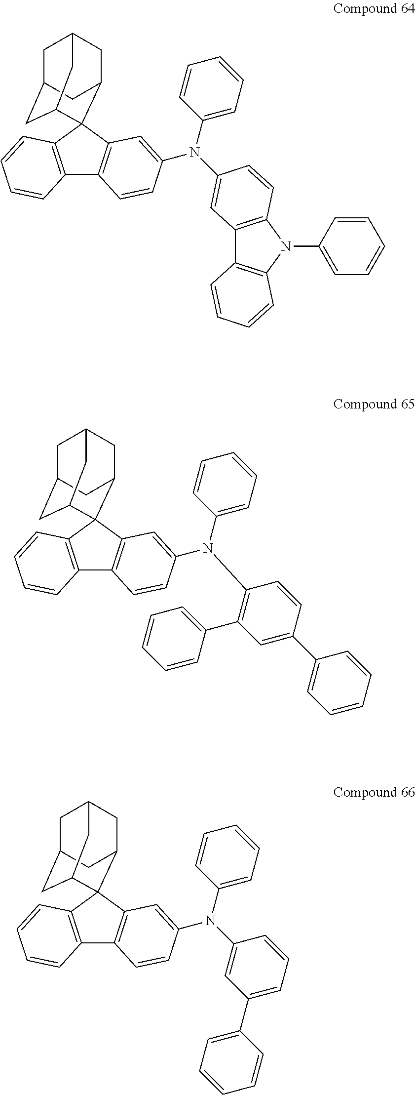
C00265
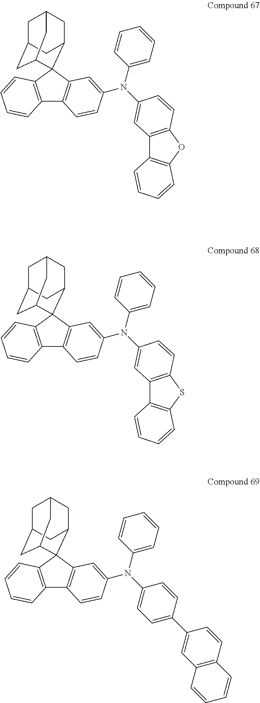
C00266
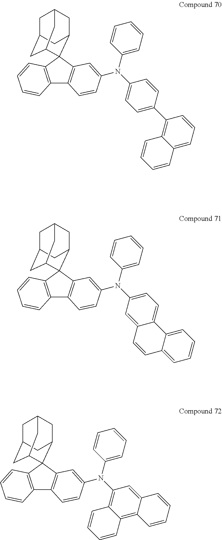
C00267

C00268
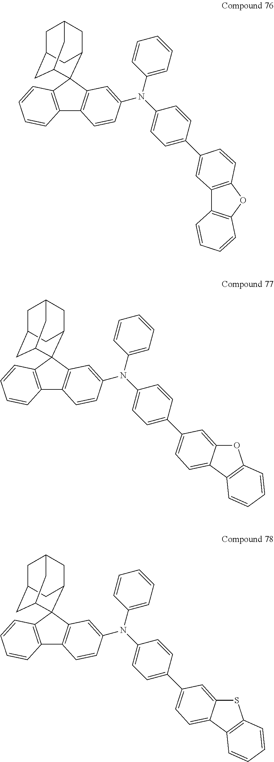
C00269
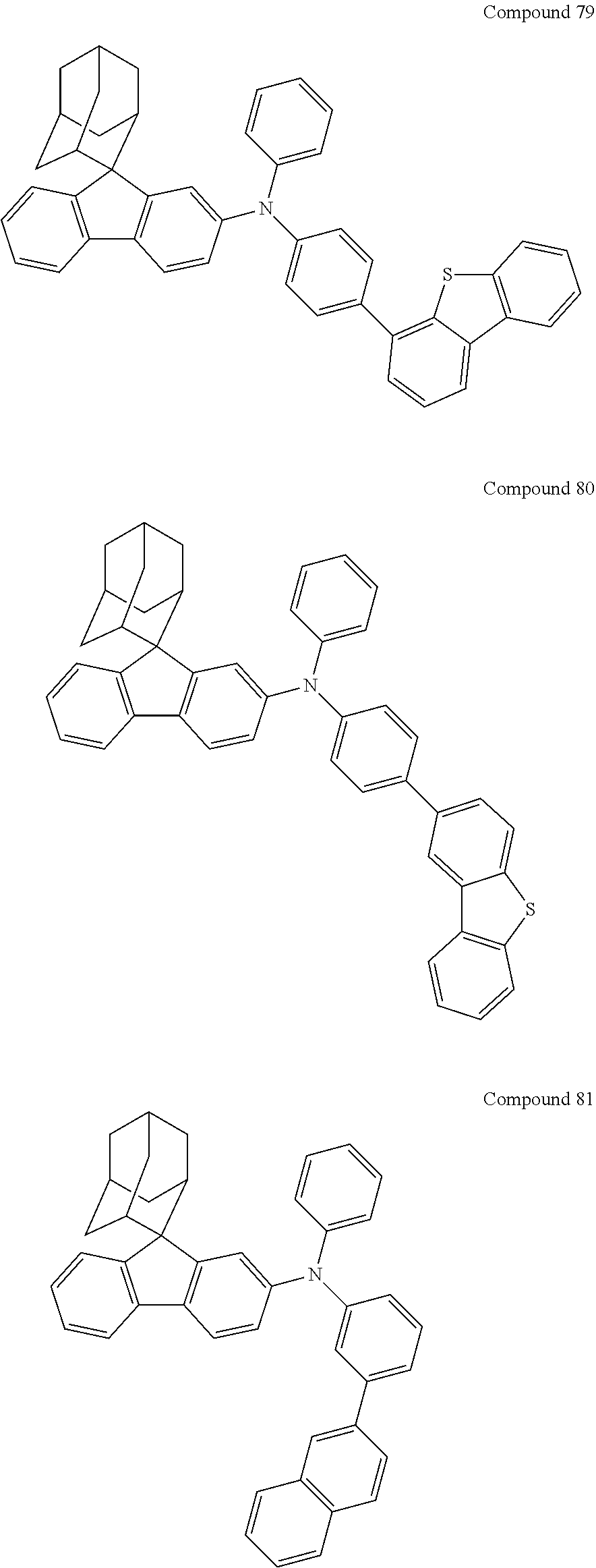
C00270

C00271
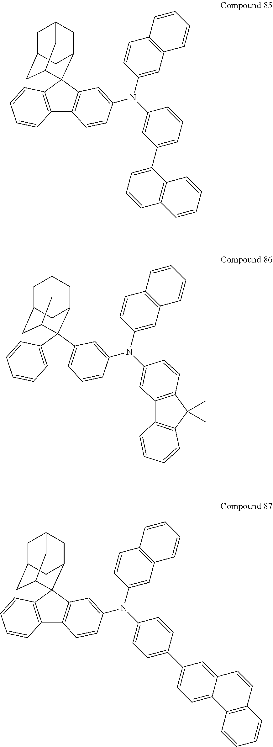
C00272

C00273
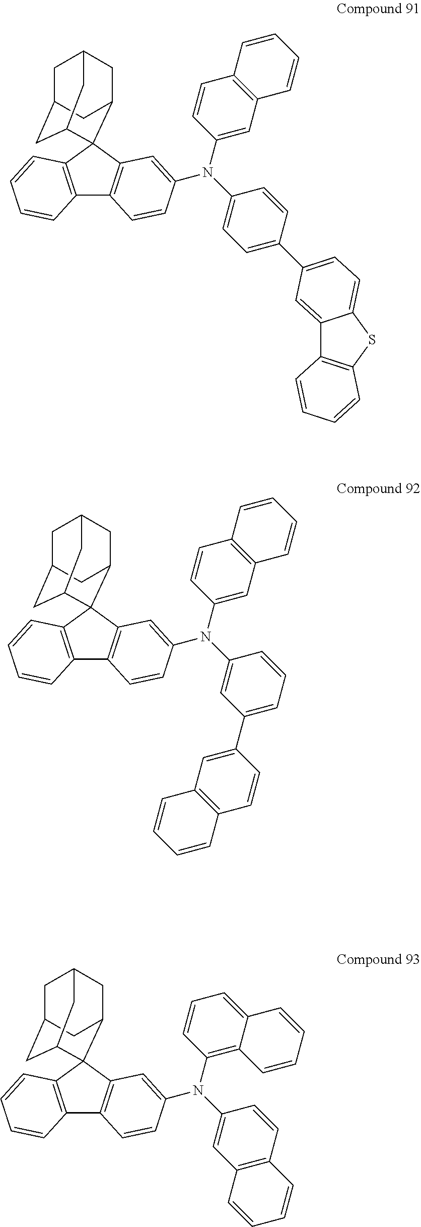
C00274

C00275
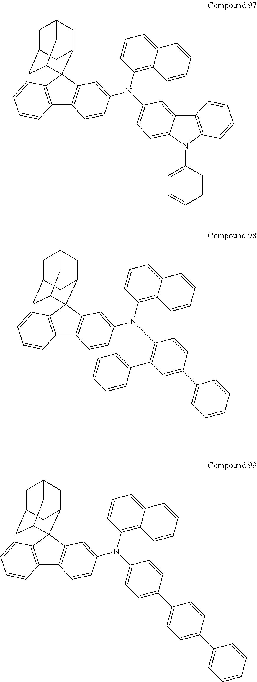
C00276
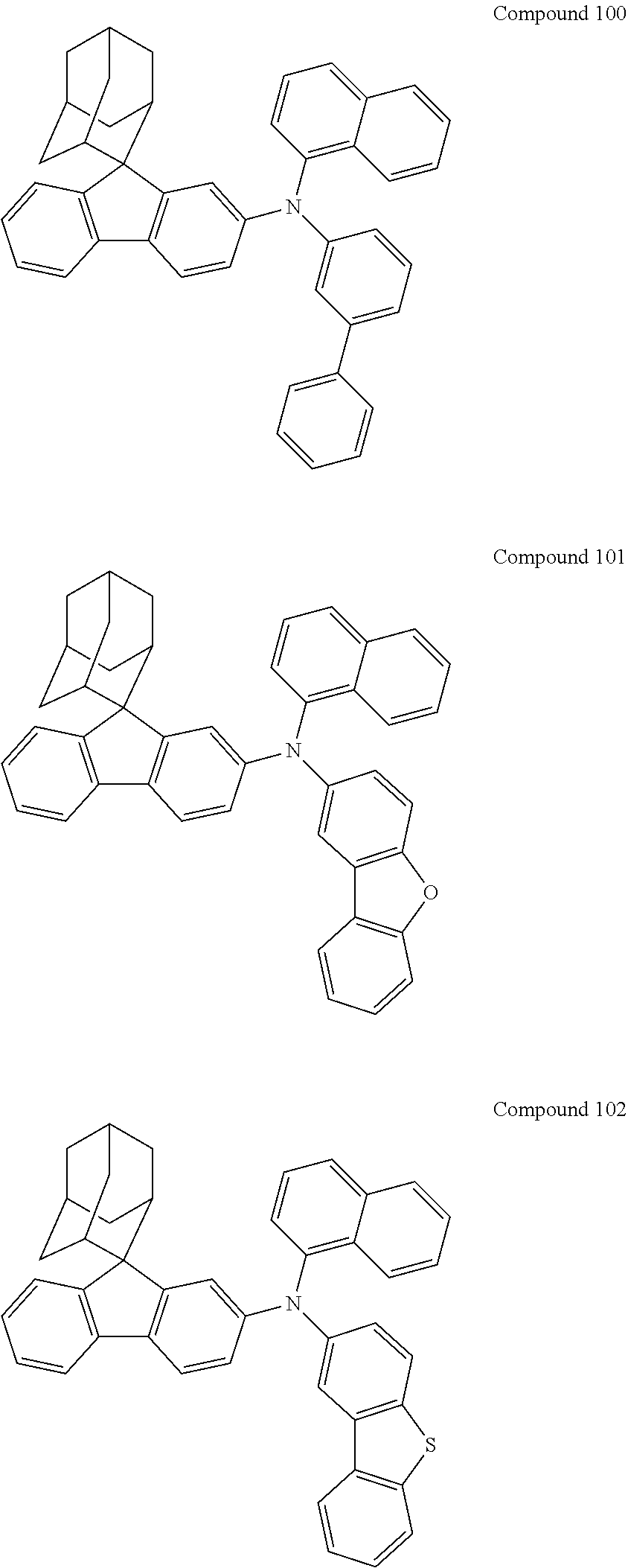
C00277

C00278

C00279
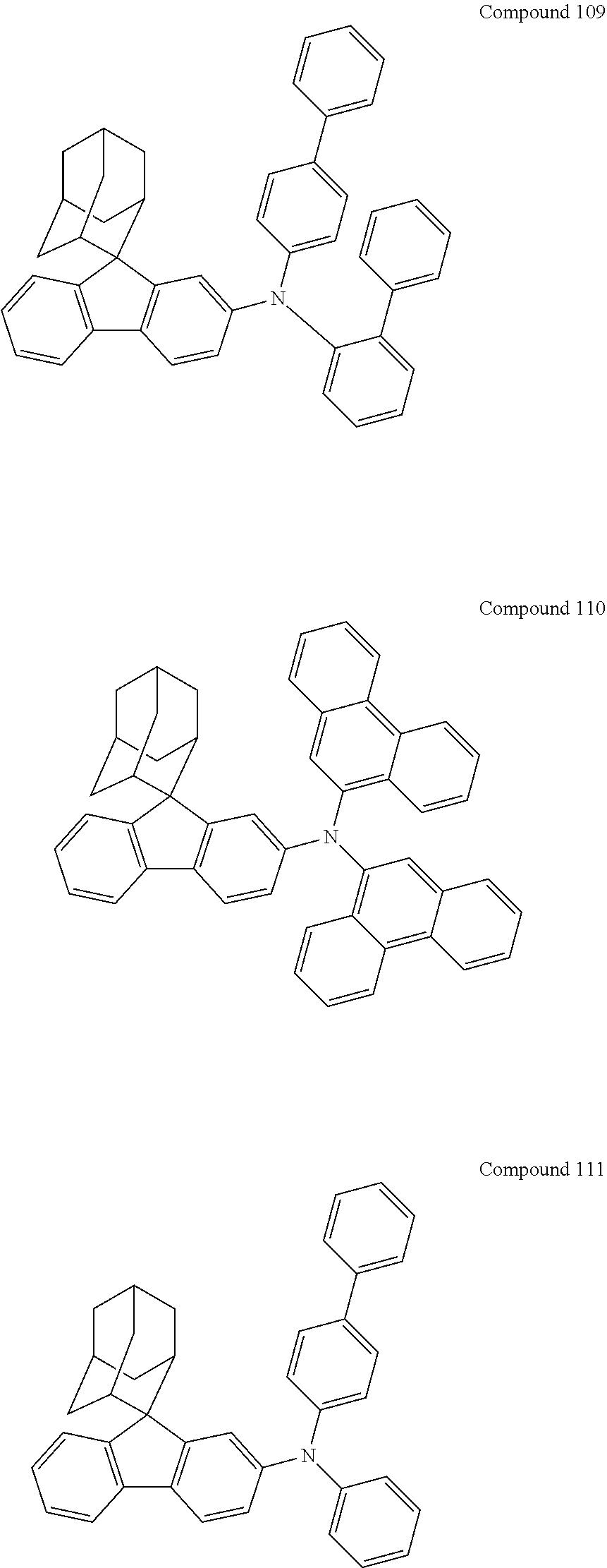
C00280
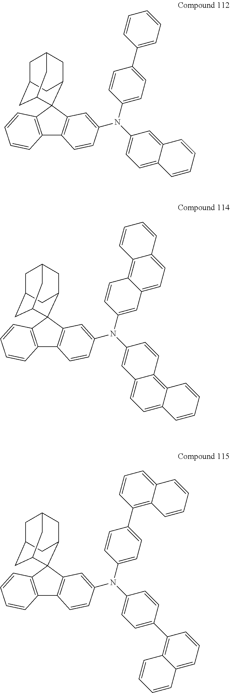
C00281
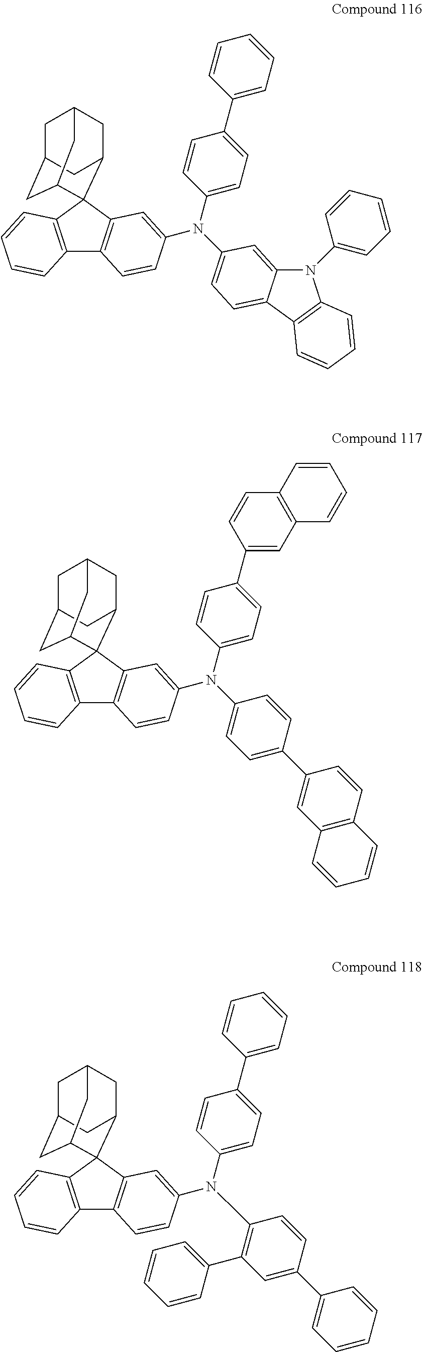
C00282

C00283
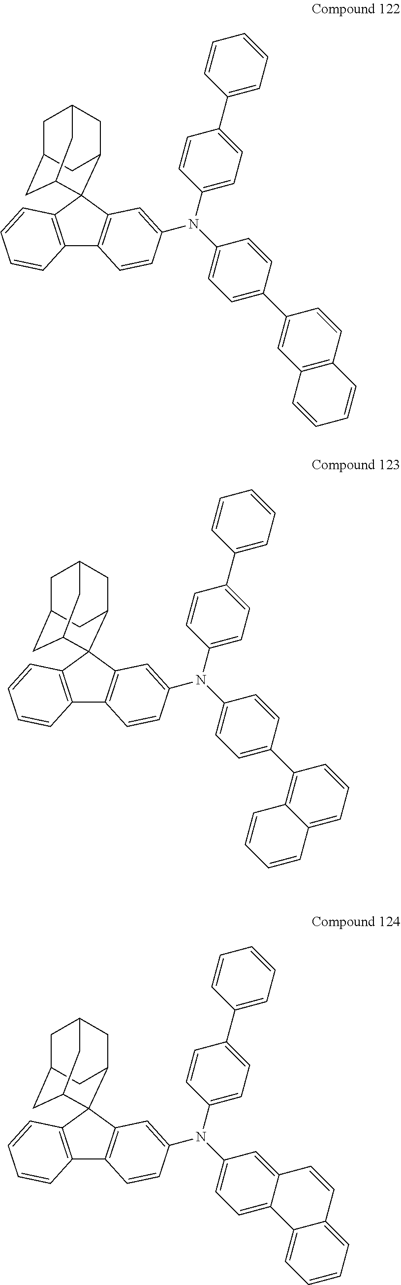
C00284
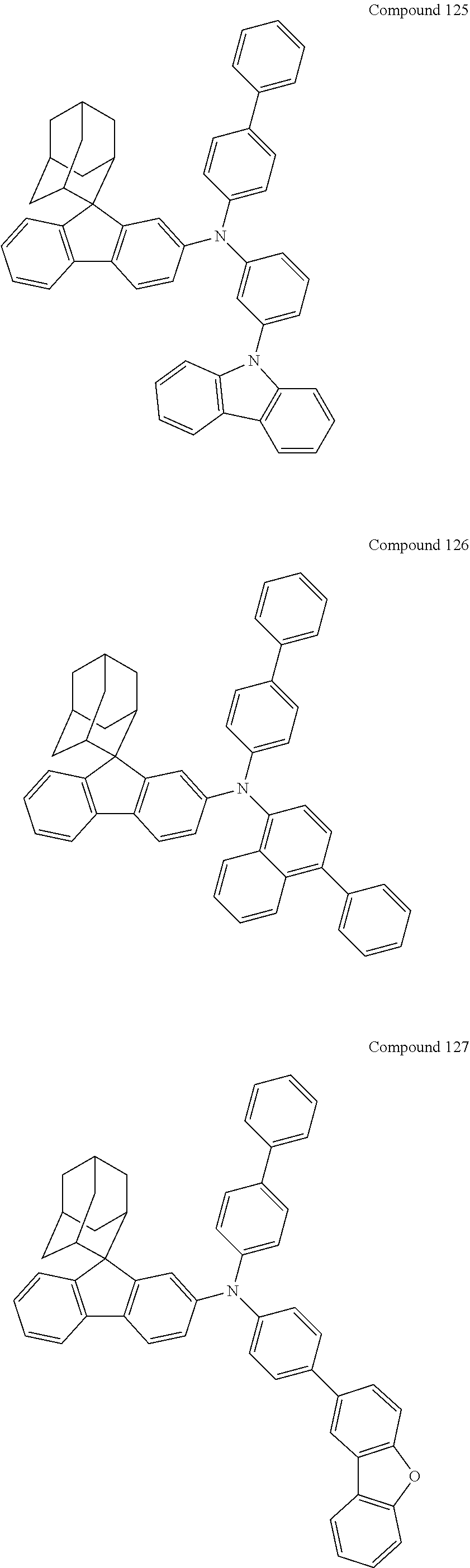
C00285

C00286
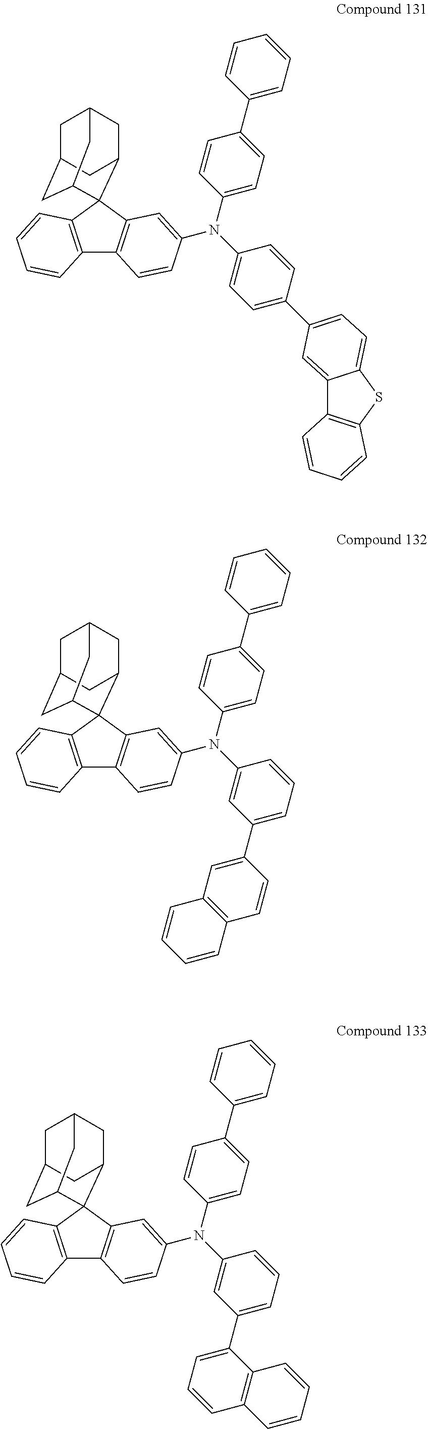
C00287

C00288
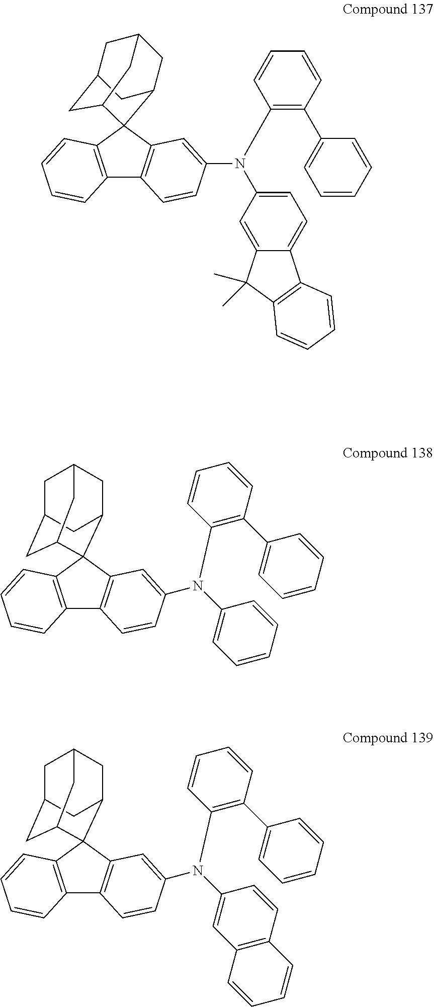
C00289

C00290
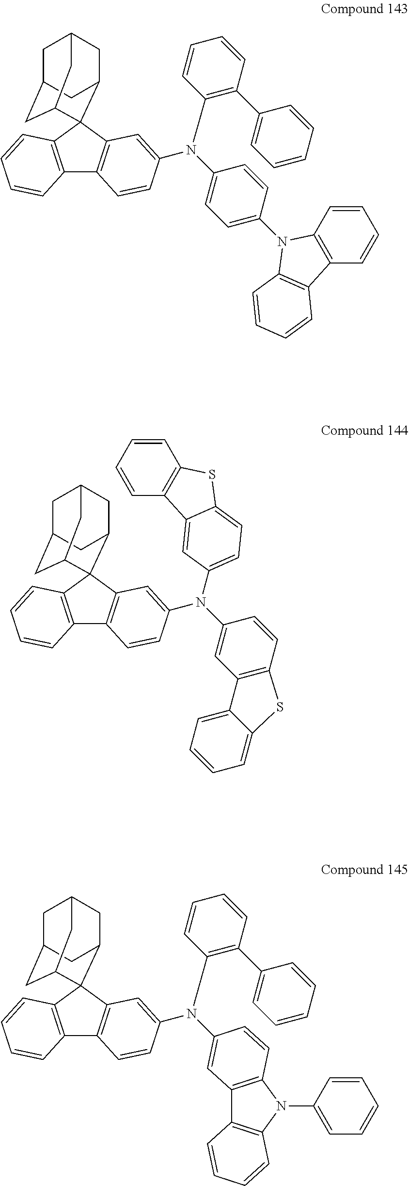
C00291

C00292
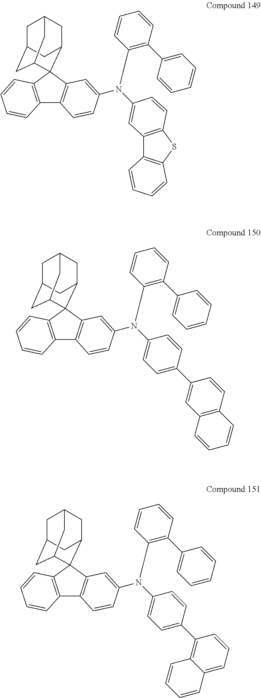
C00293

C00294
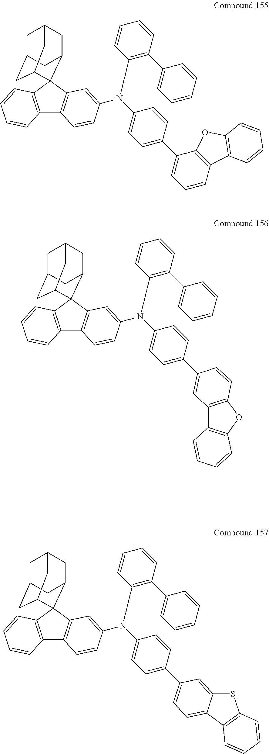
C00295
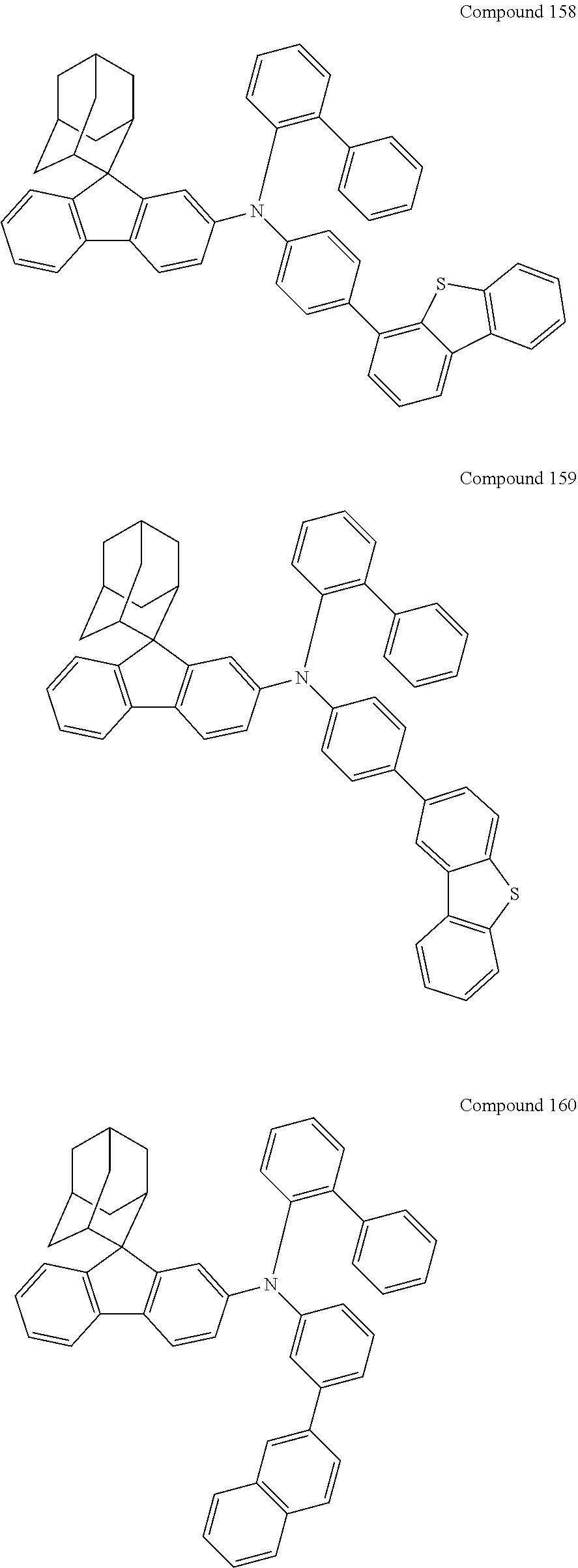
C00296
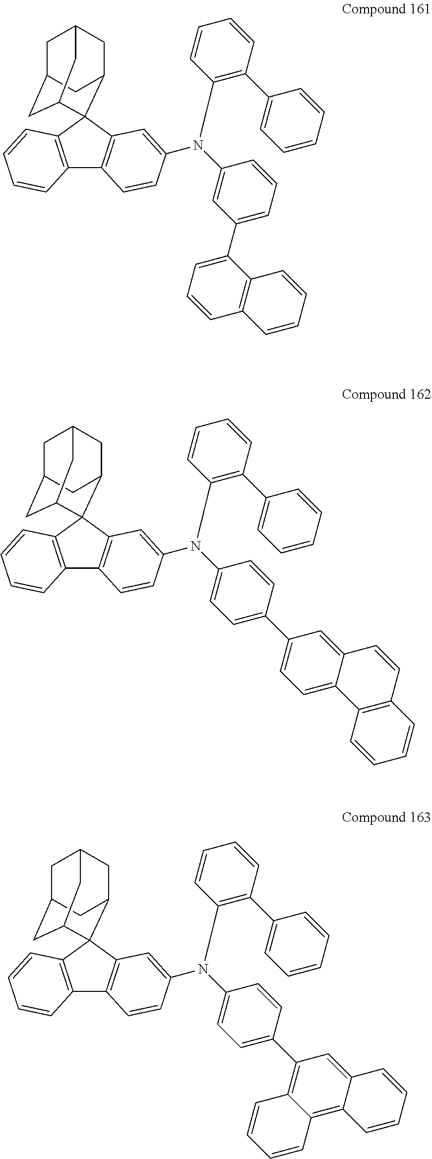
C00297

C00298
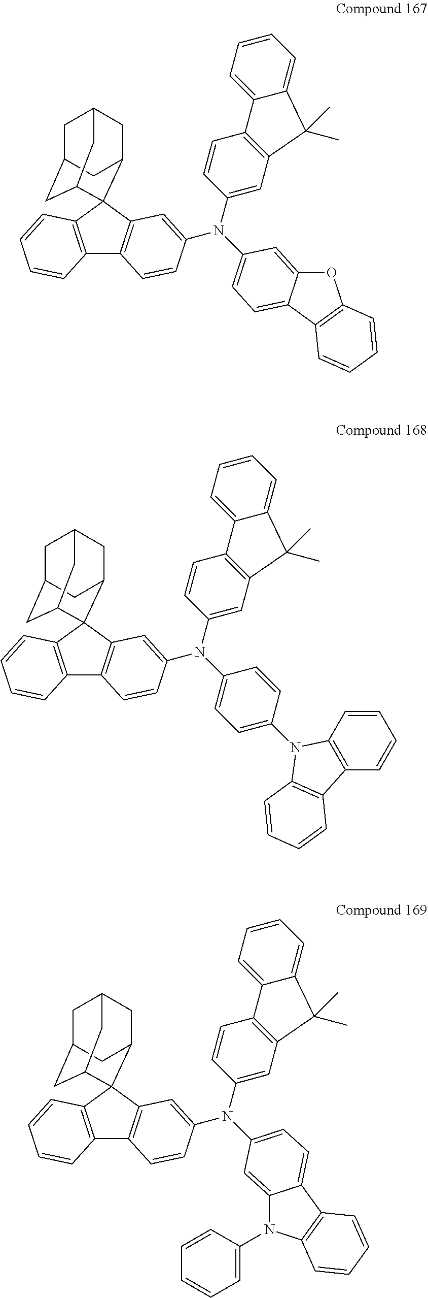
C00299
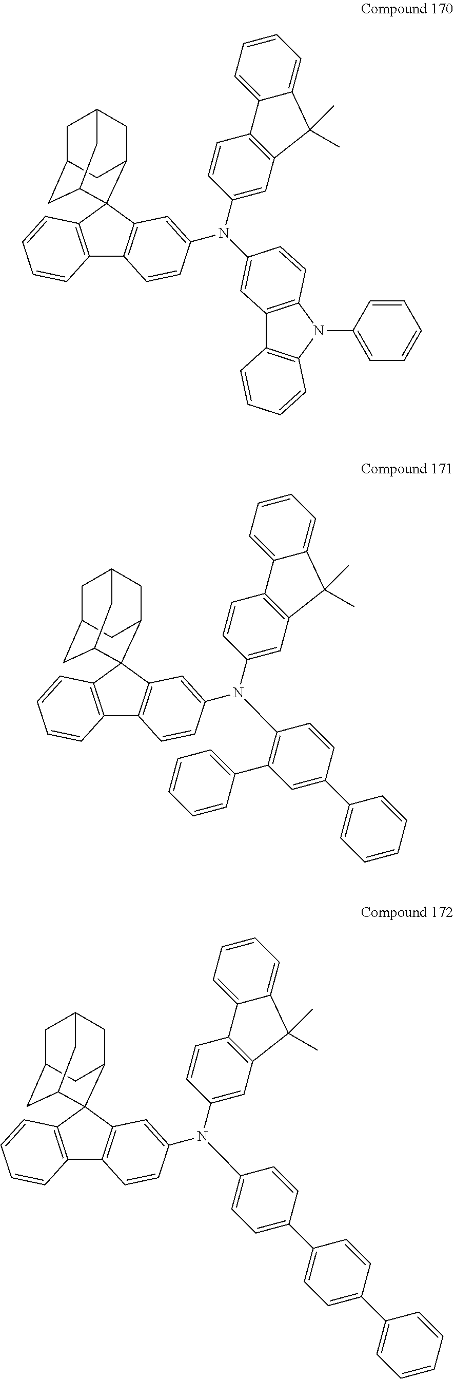
C00300
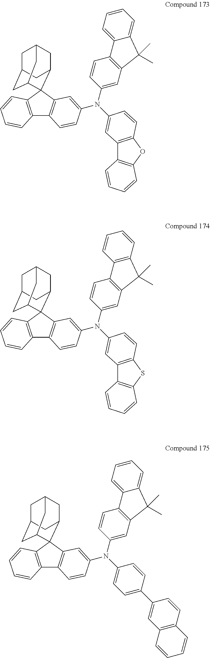
C00301
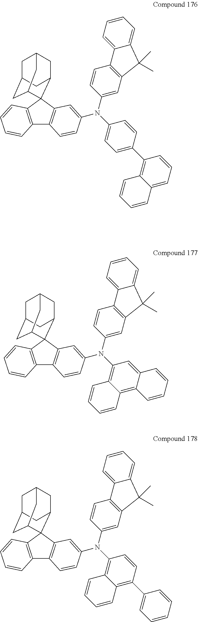
C00302
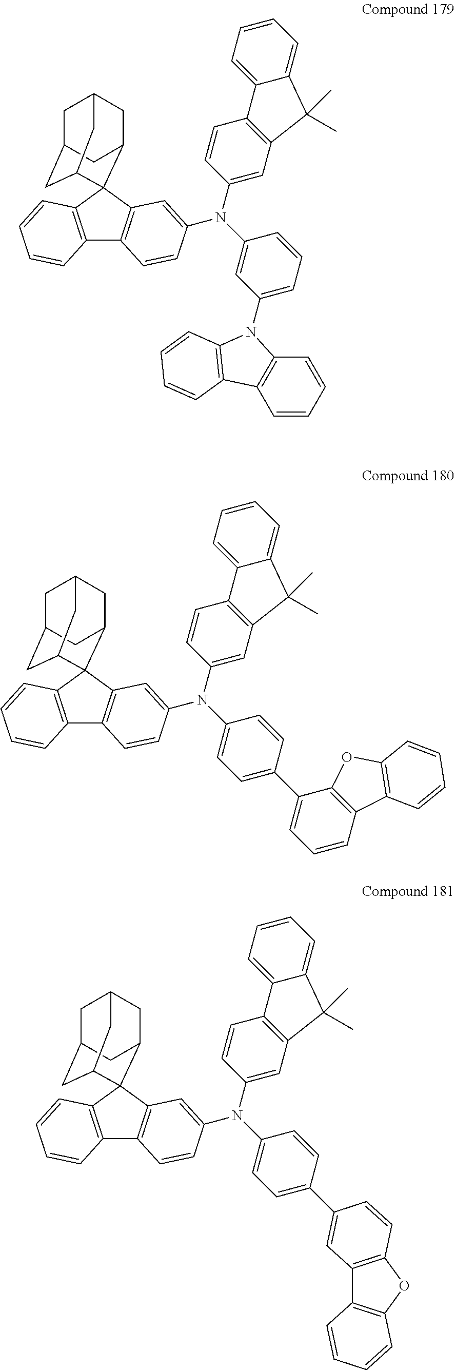
C00303

C00304
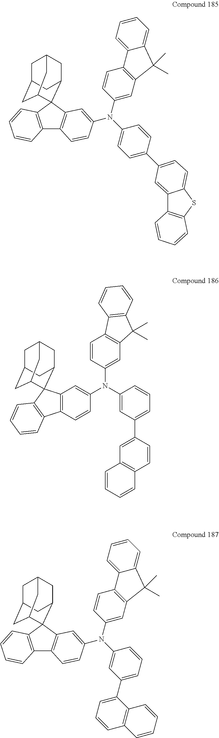
C00305
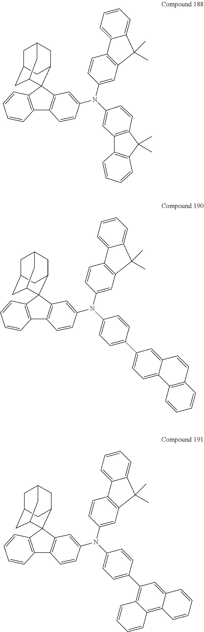
C00306
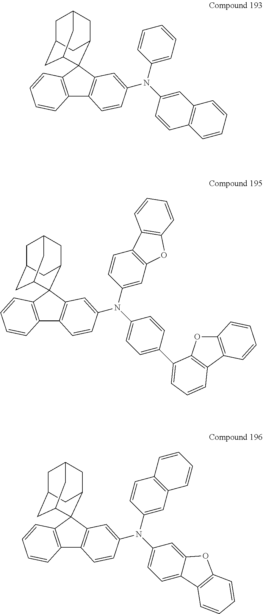
C00307

C00308

C00309
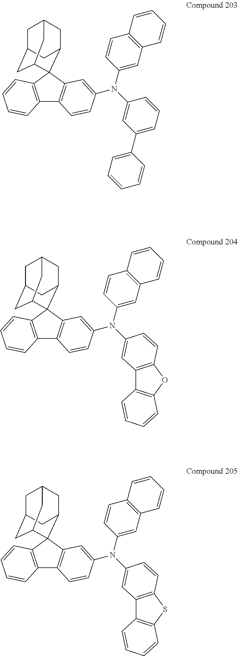
C00310
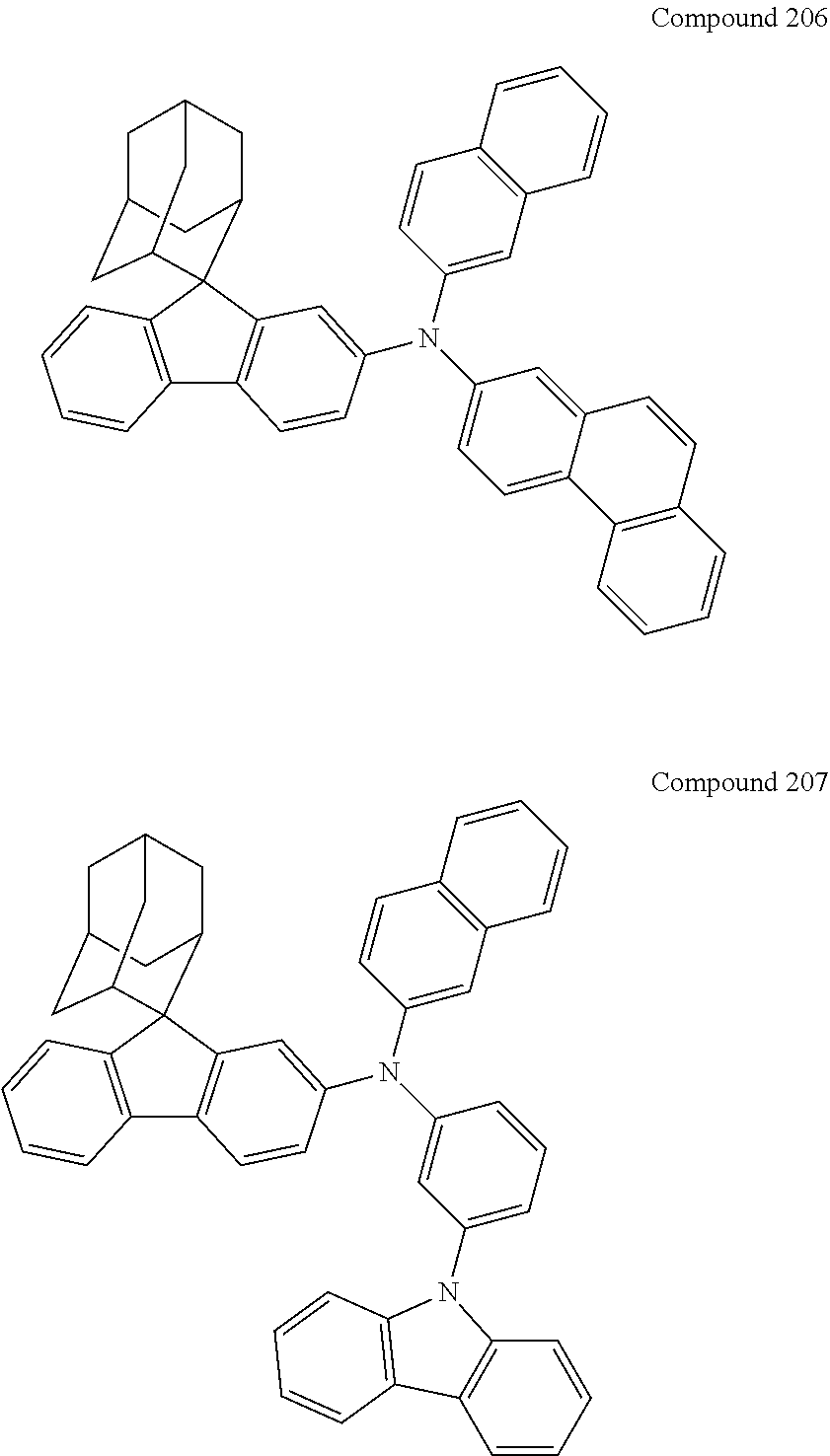
C00311
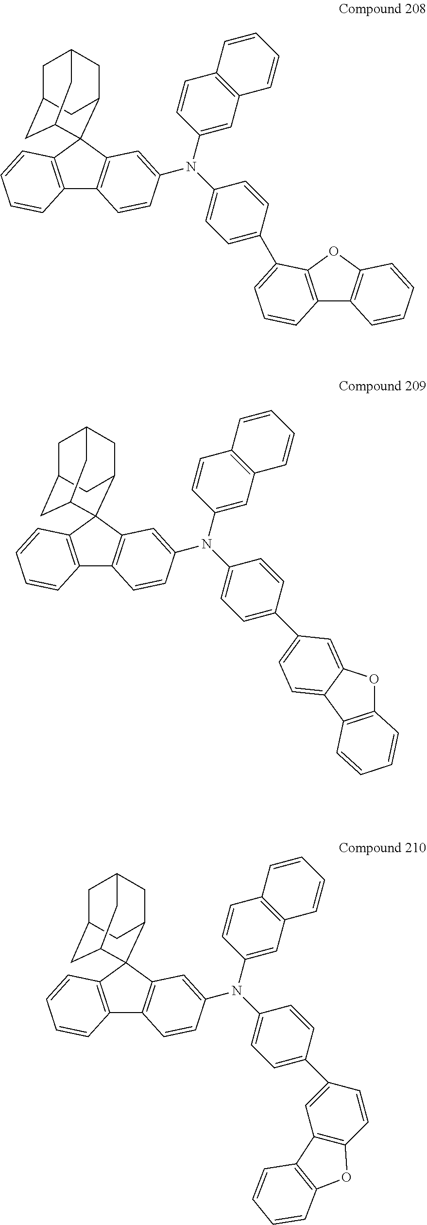
C00312
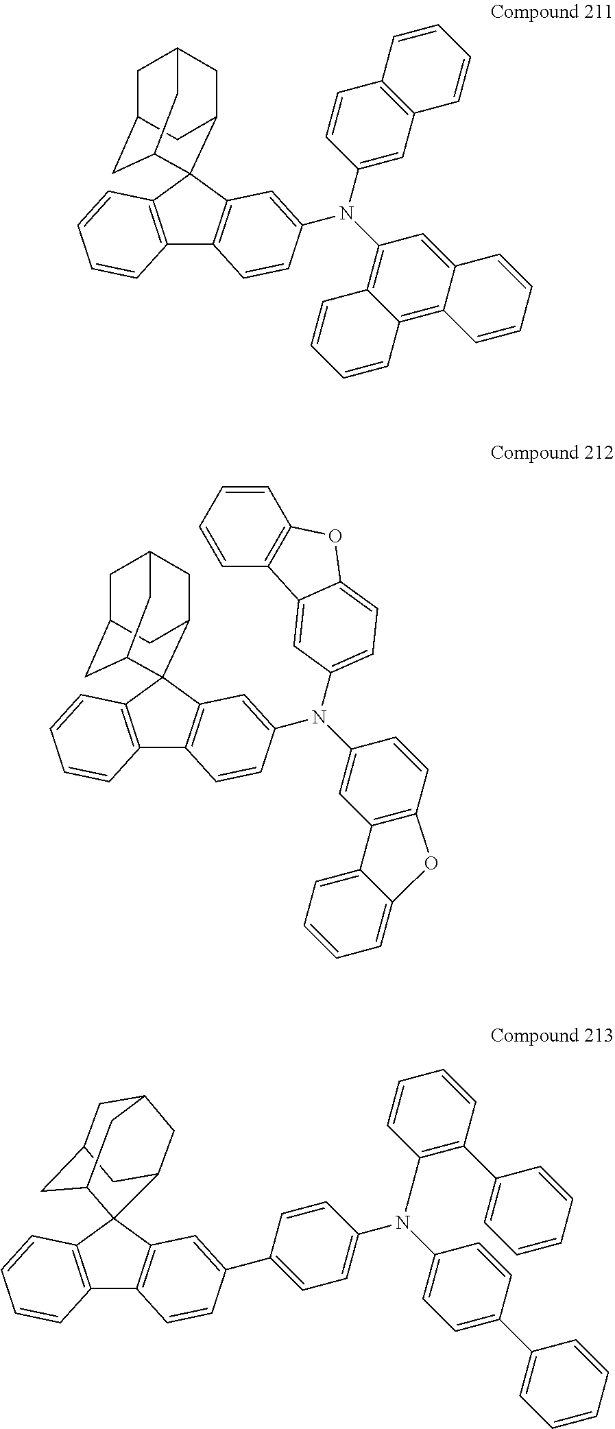
C00313
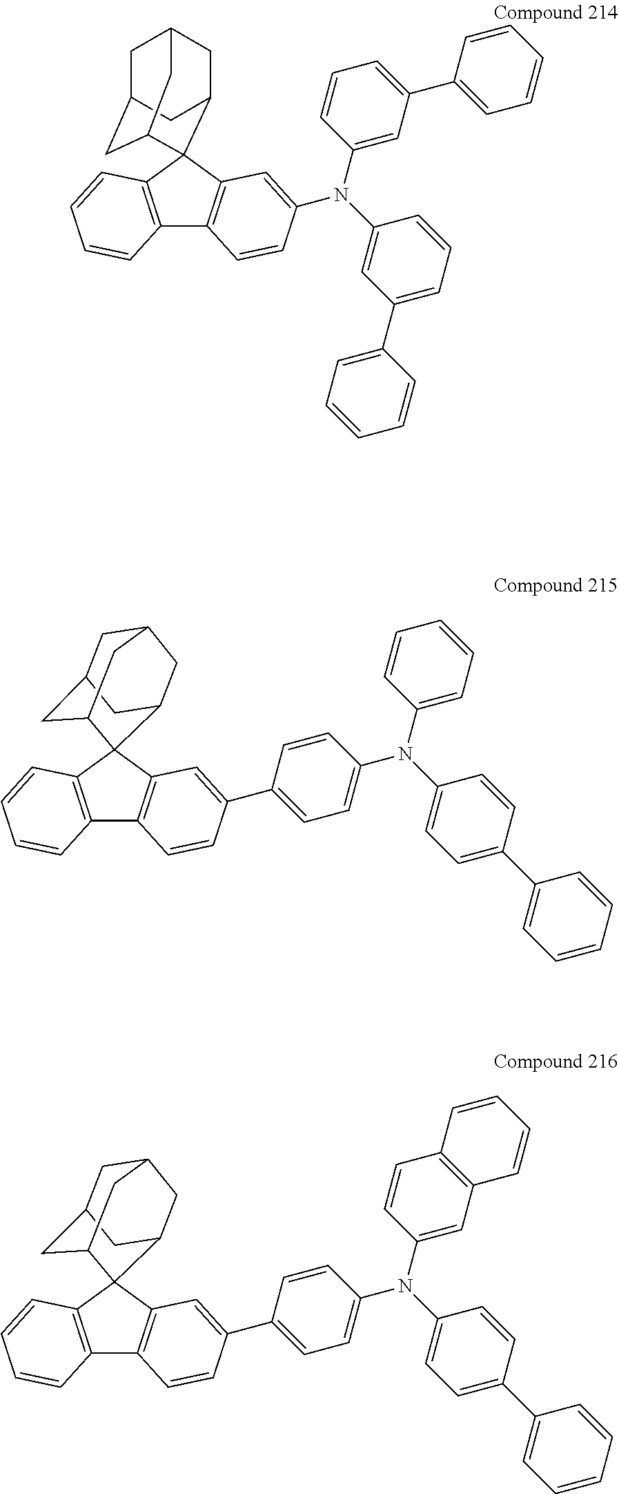
C00314

C00315
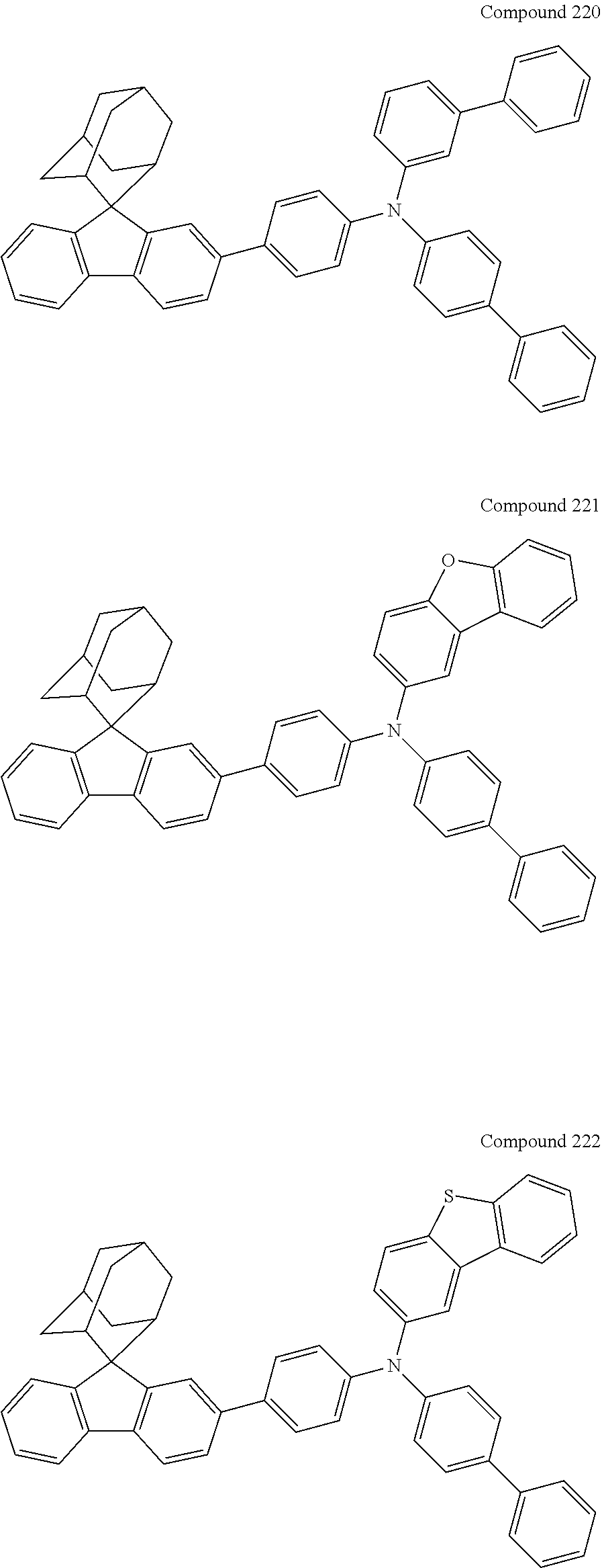
C00316

C00317

C00318
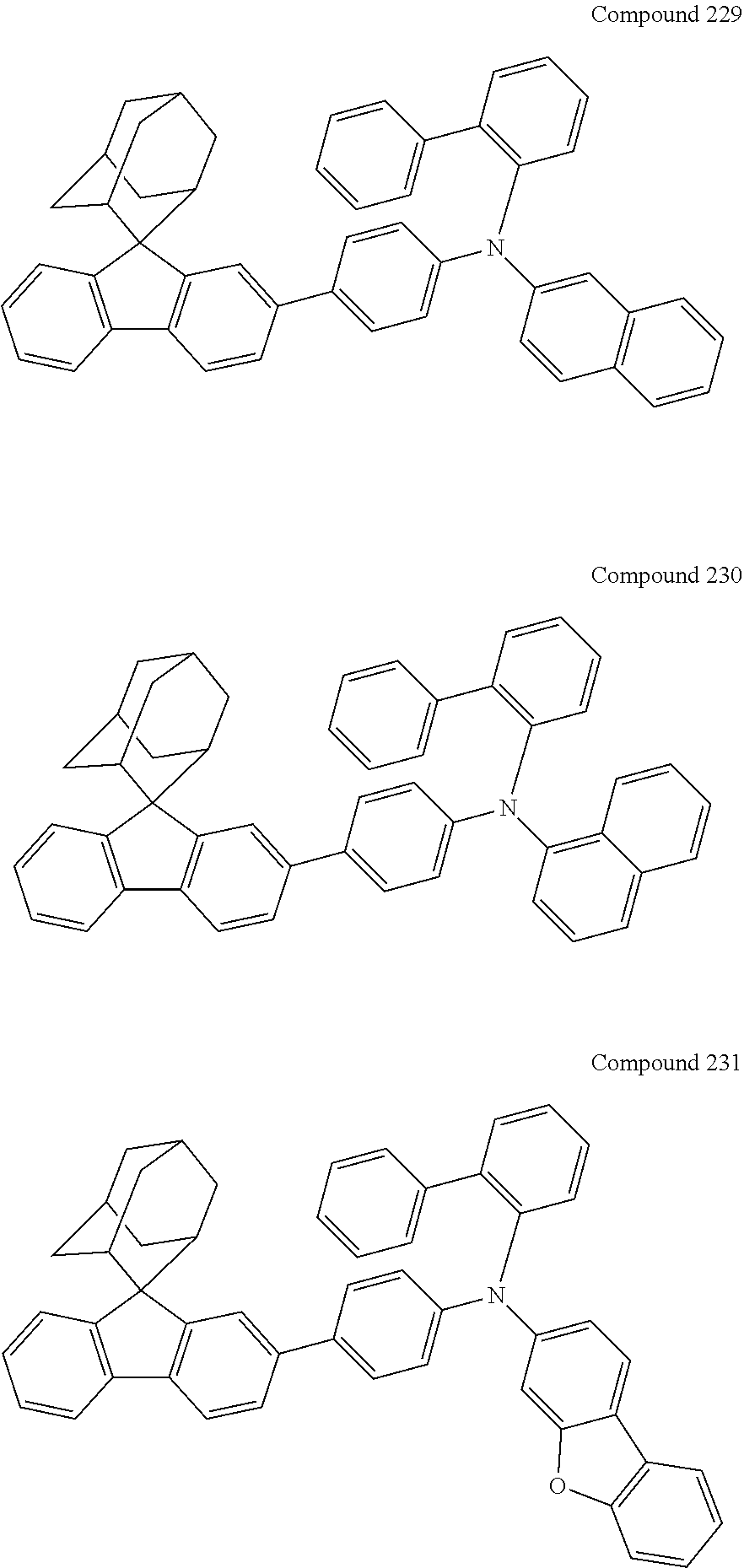
C00319
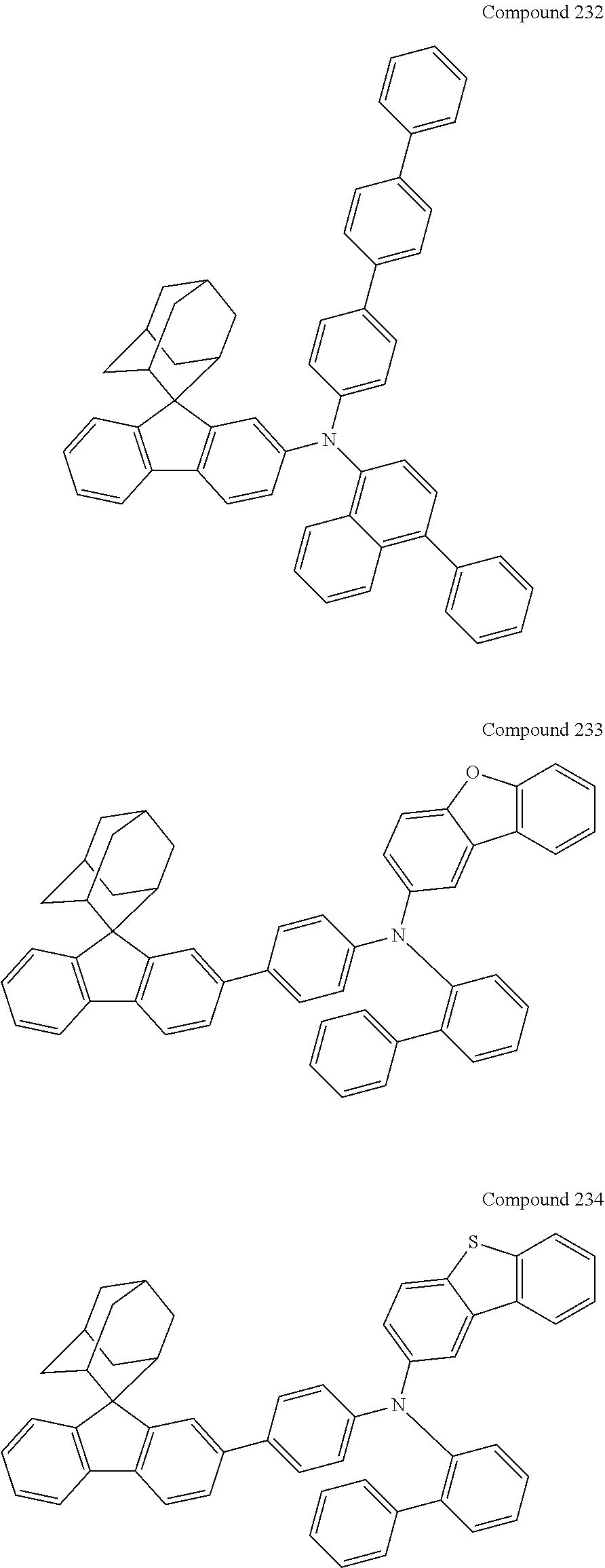
C00320
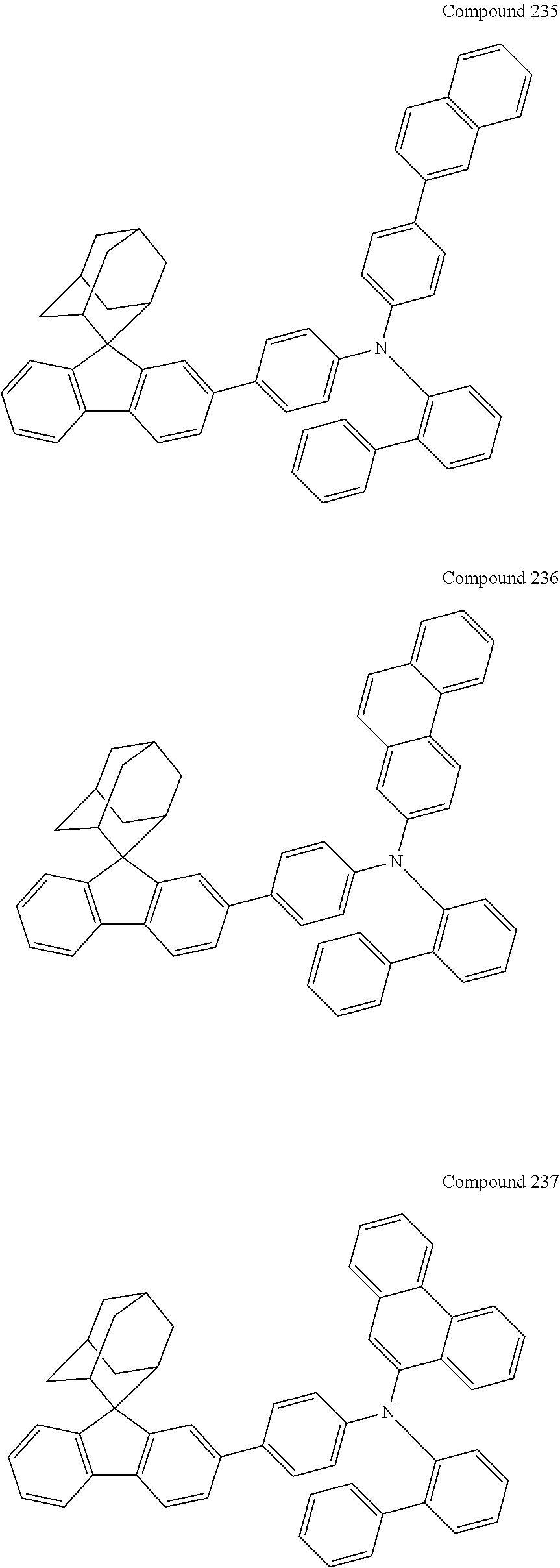
C00321

C00322

C00323
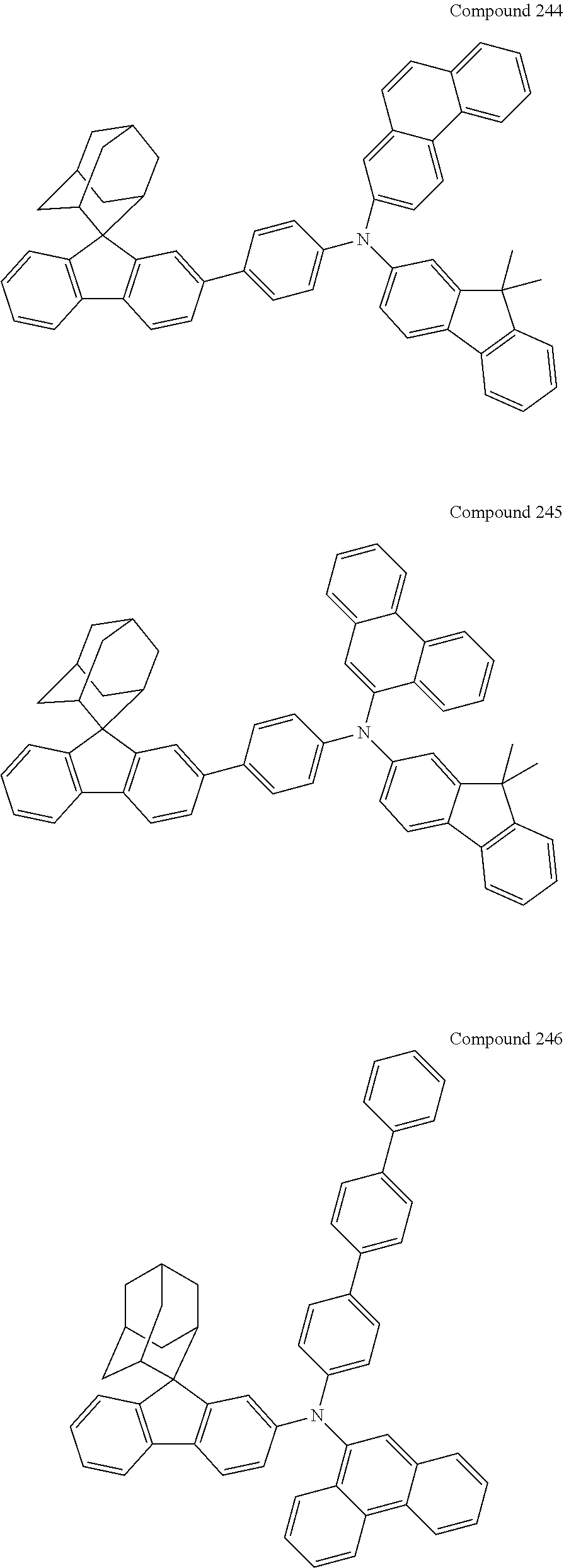
C00324
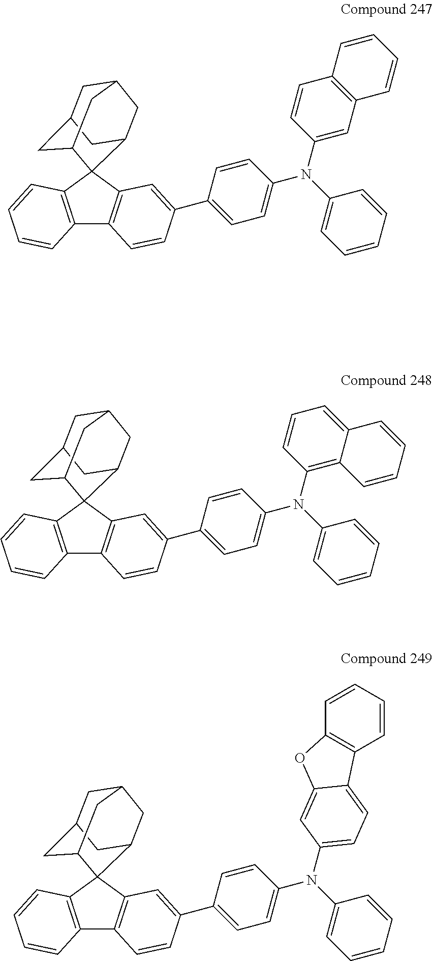
C00325

C00326

C00327

C00328
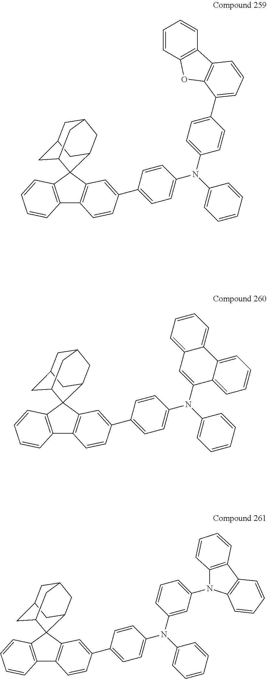
C00329

C00330
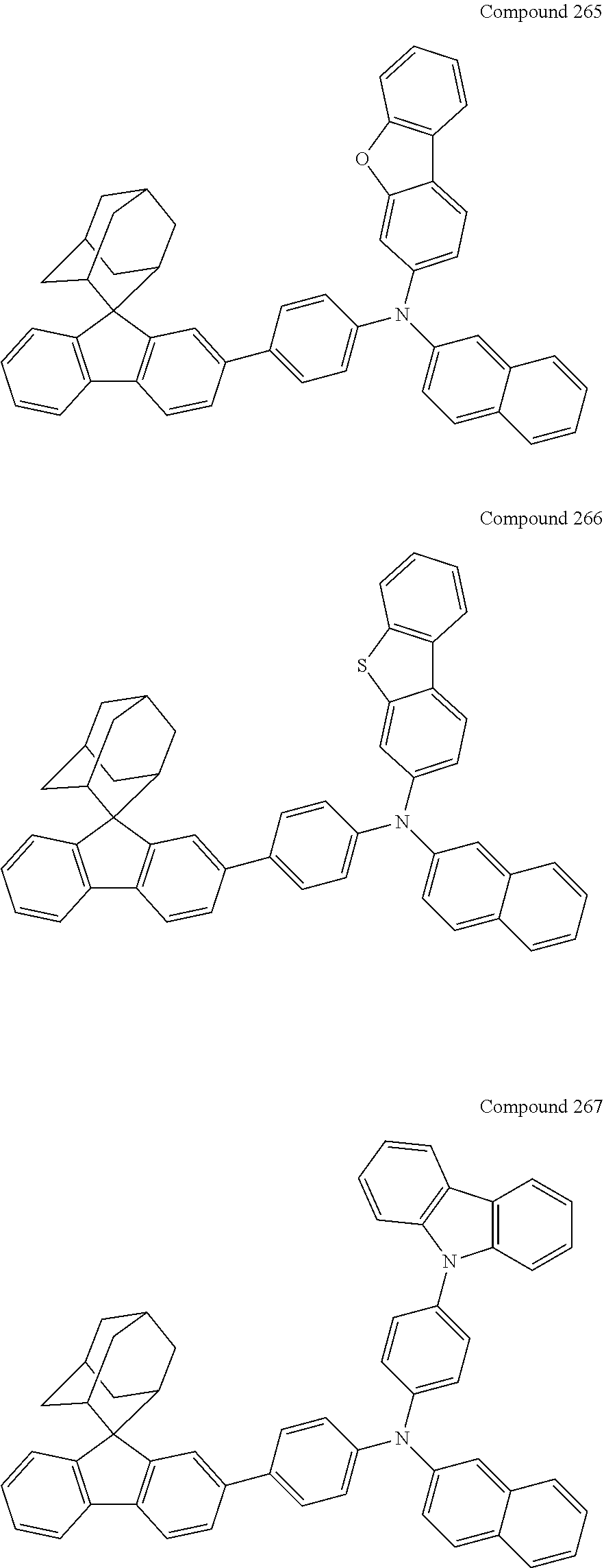
C00331
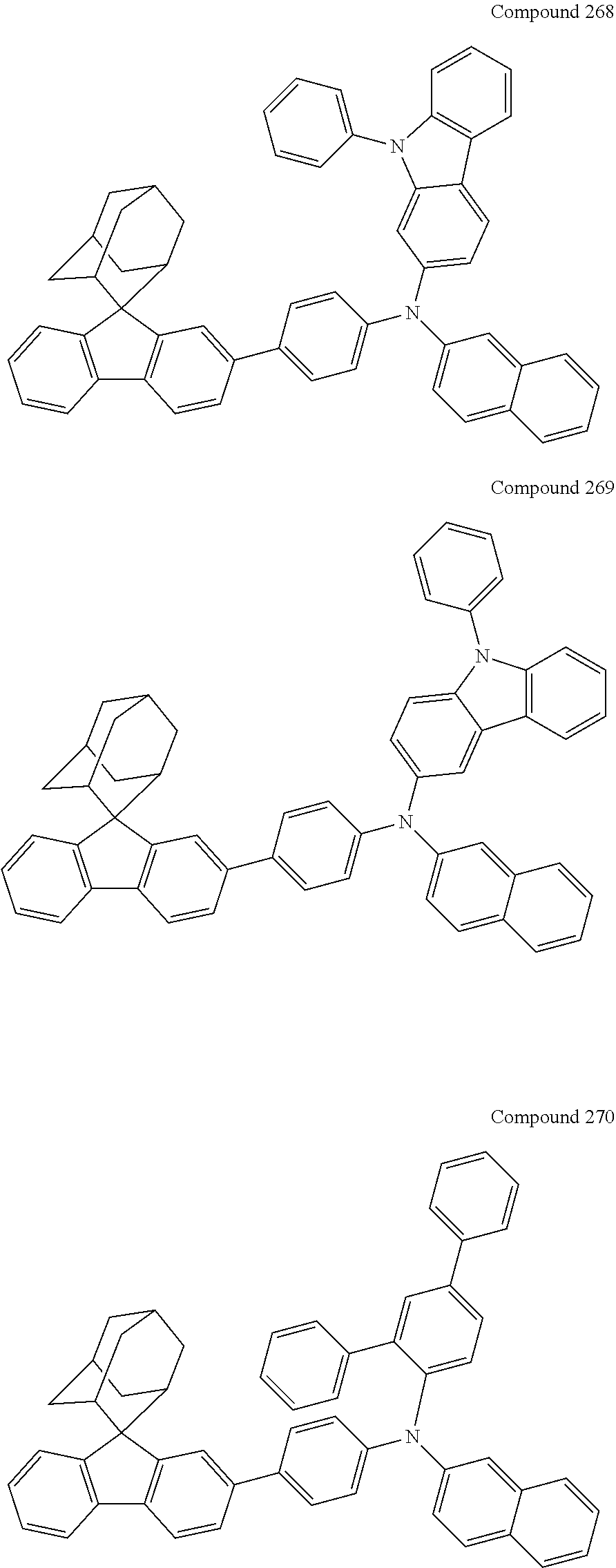
C00332
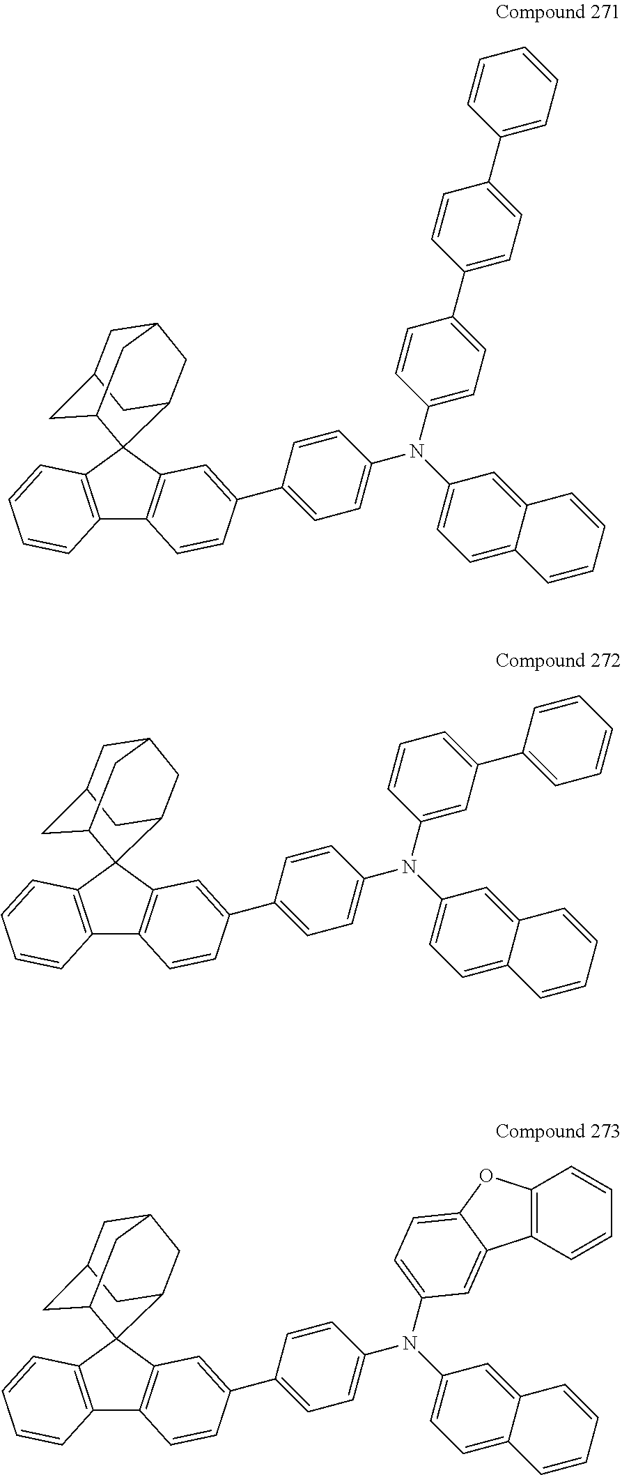
C00333
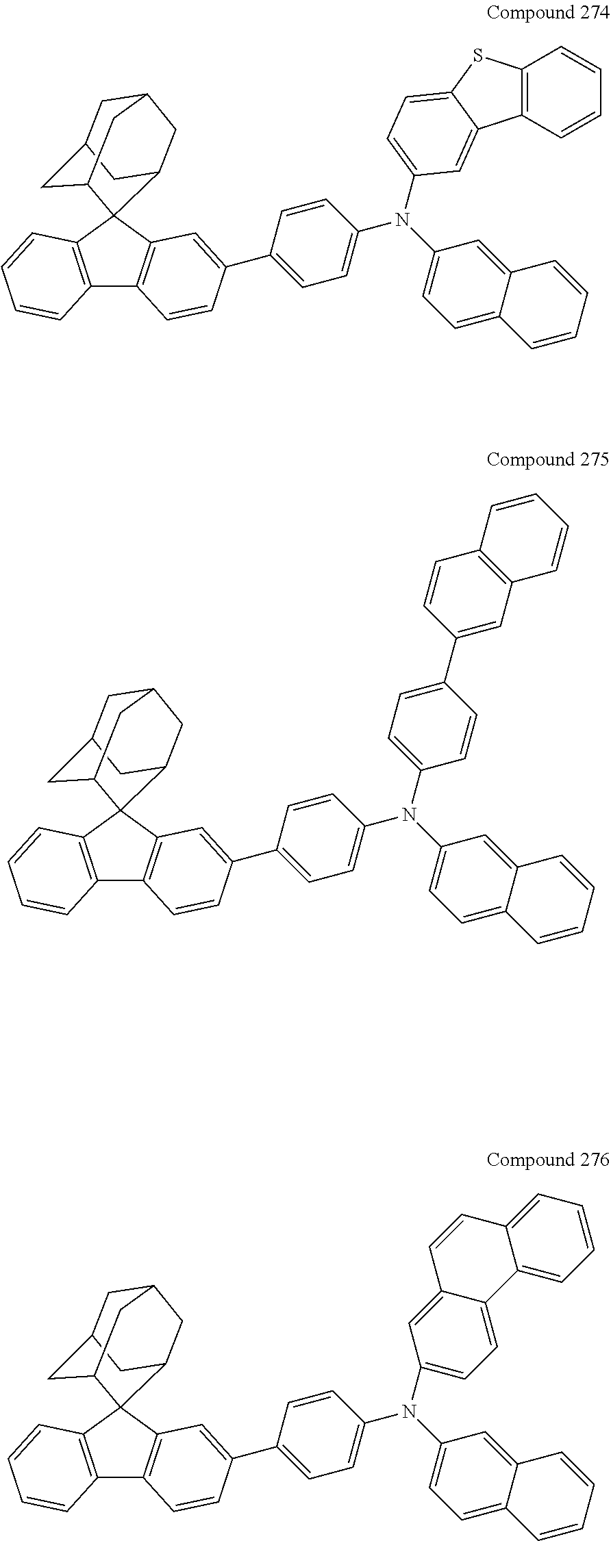
C00334

C00335
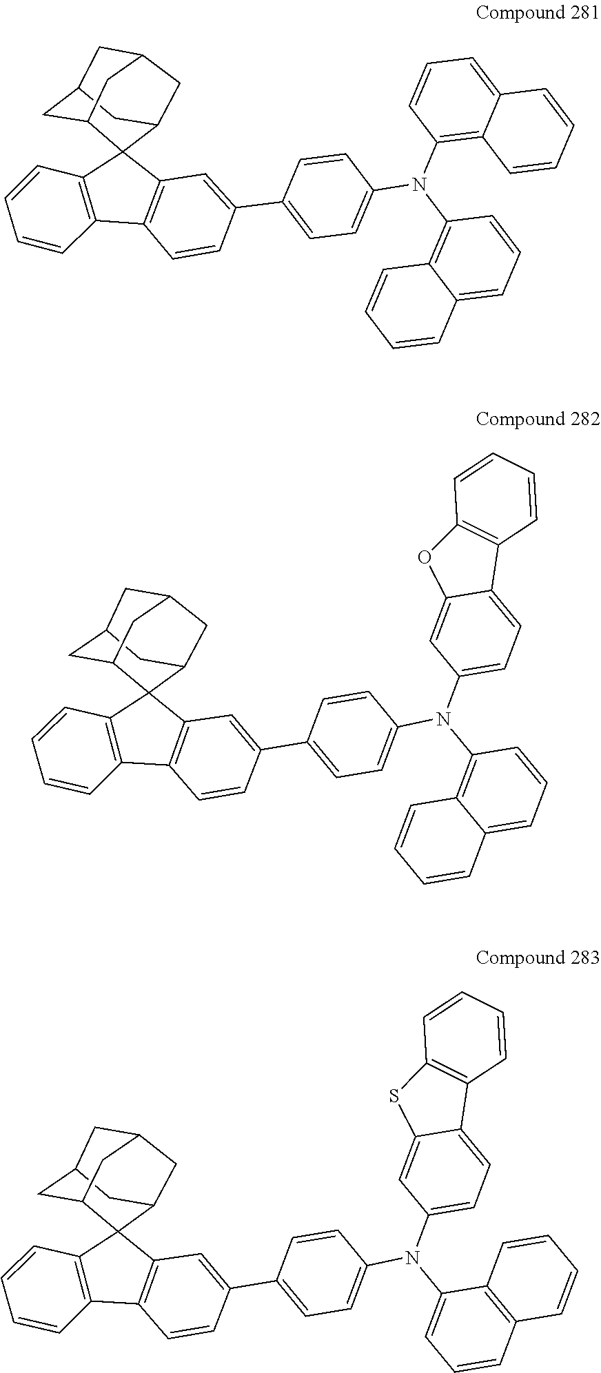
C00336
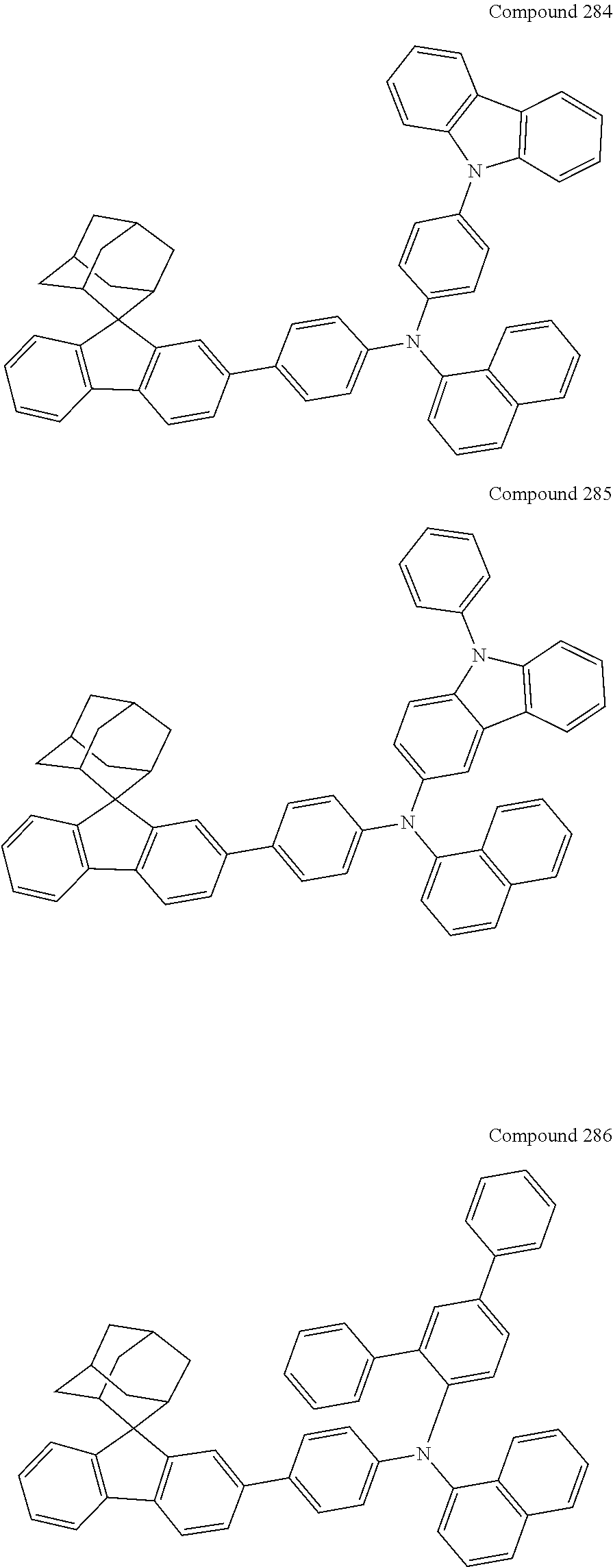
C00337
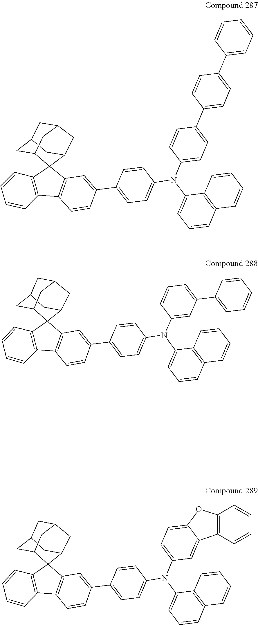
C00338
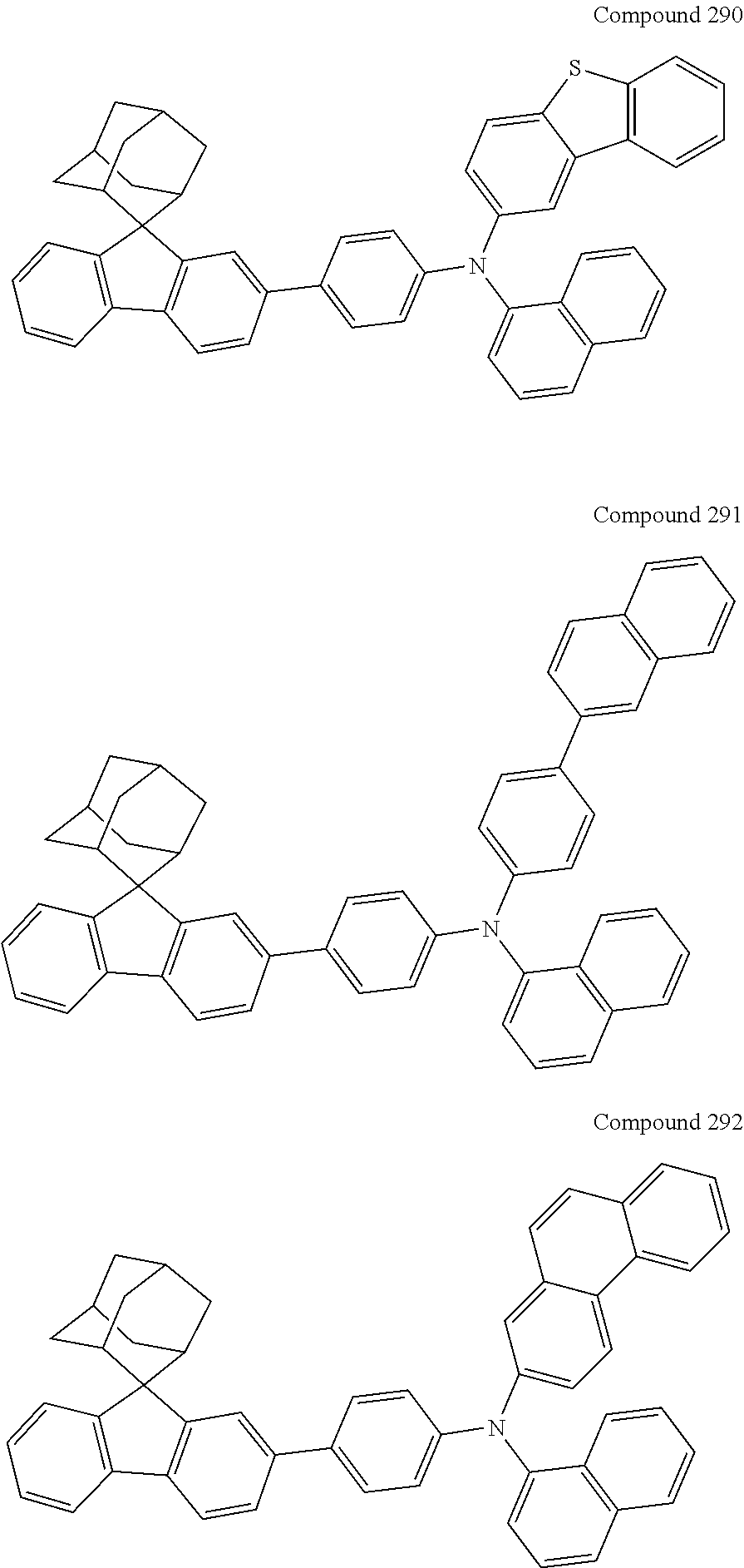
C00339
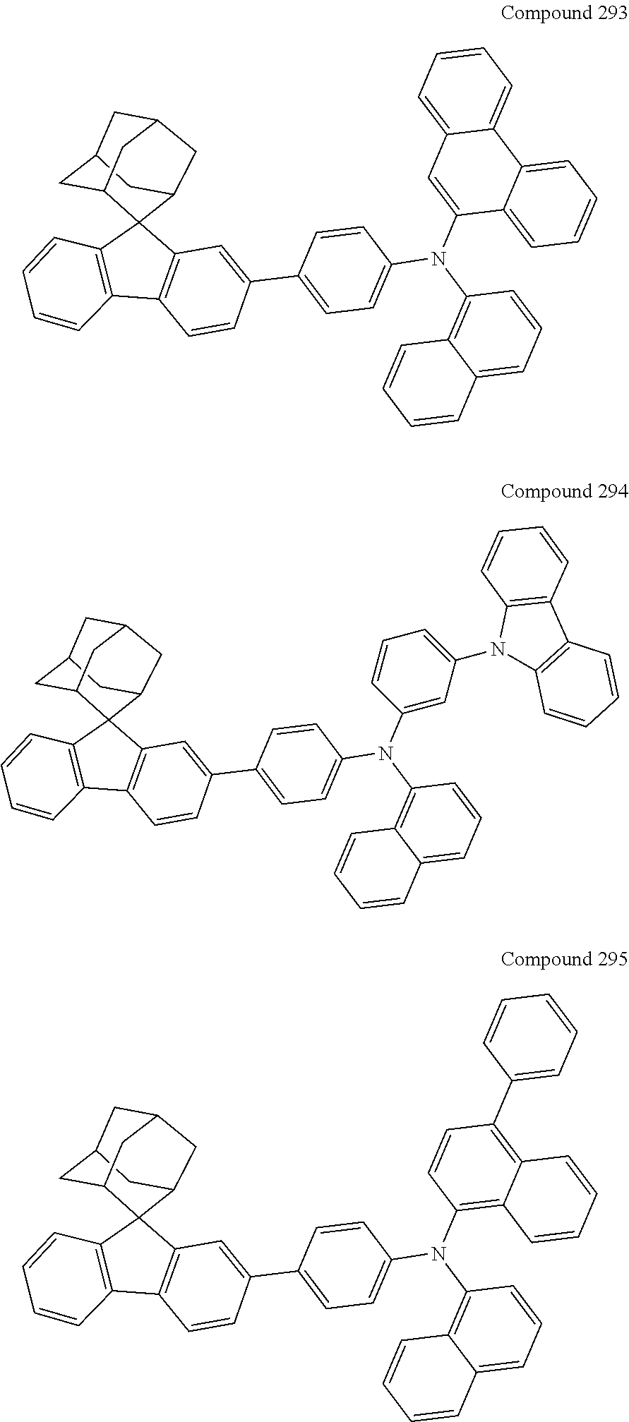
C00340
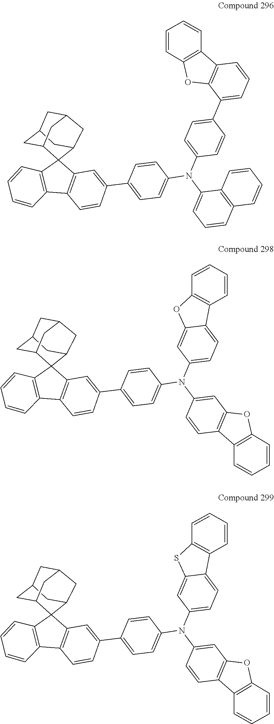
C00341

C00342
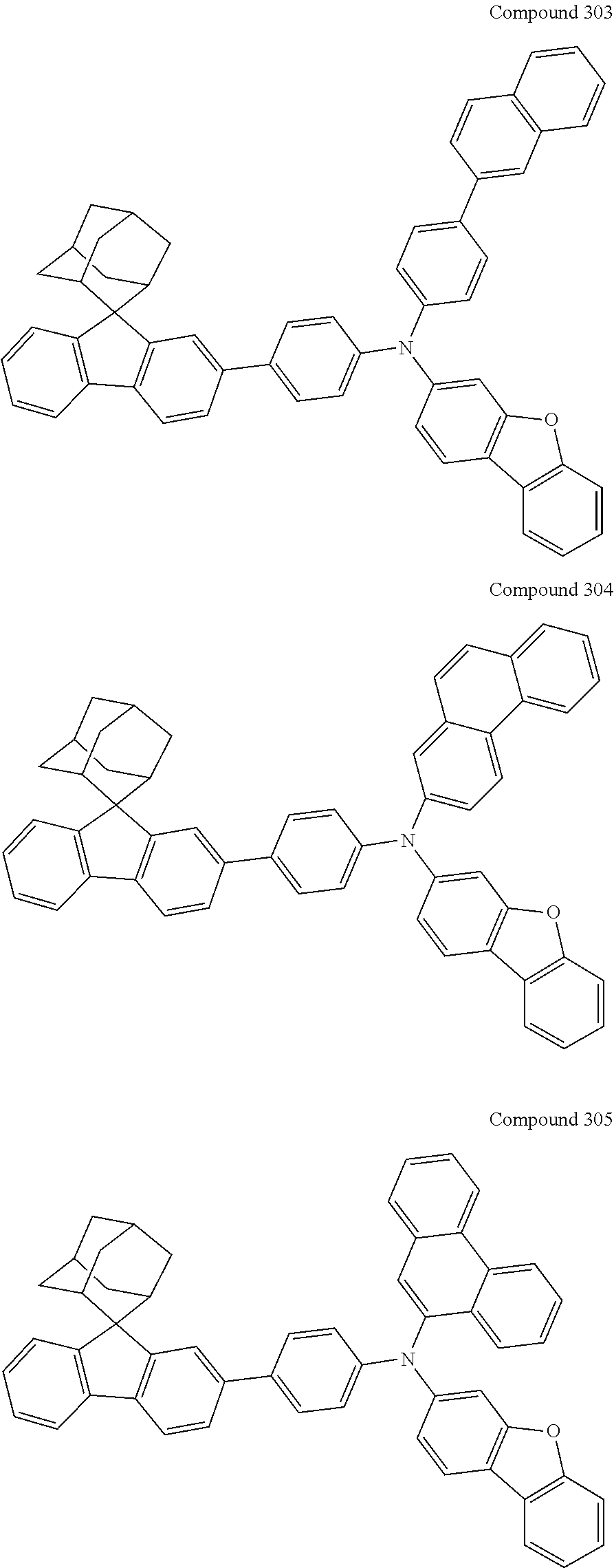
C00343

C00344
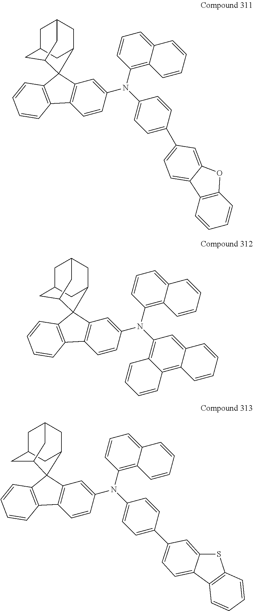
C00345
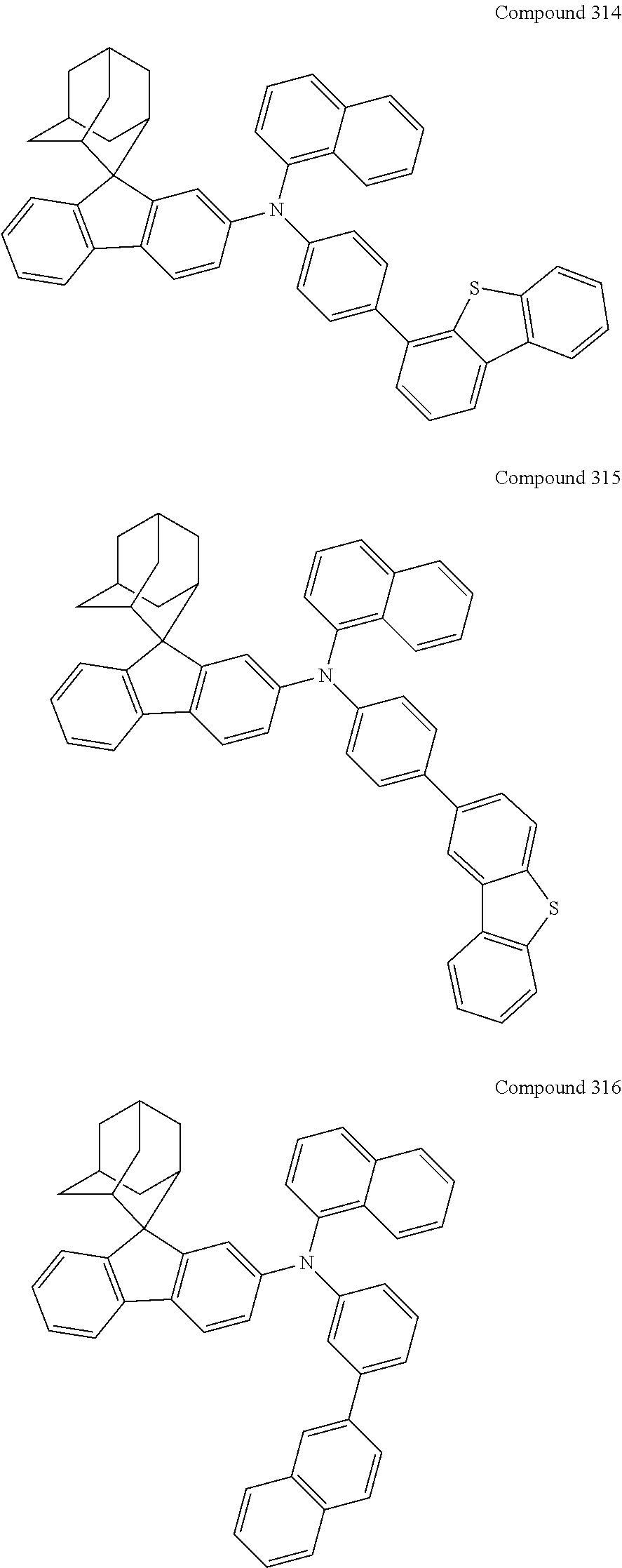
C00346
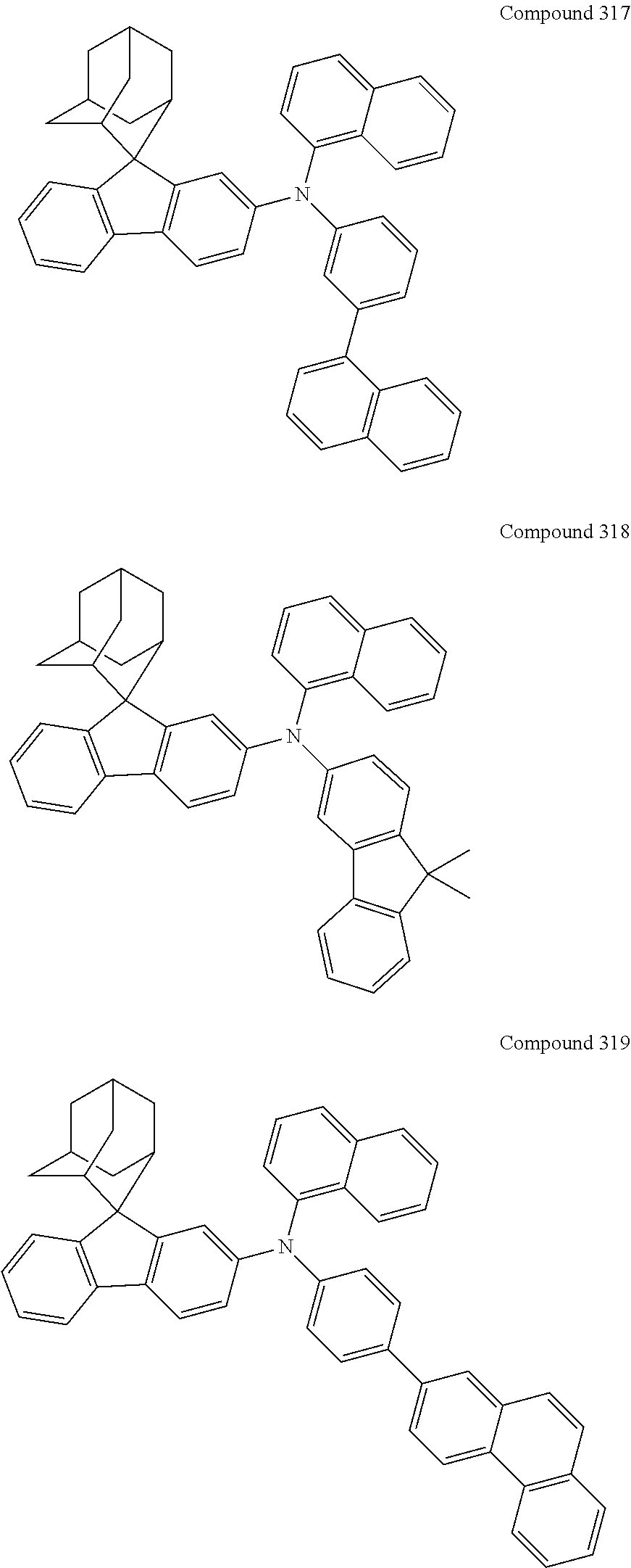
C00347
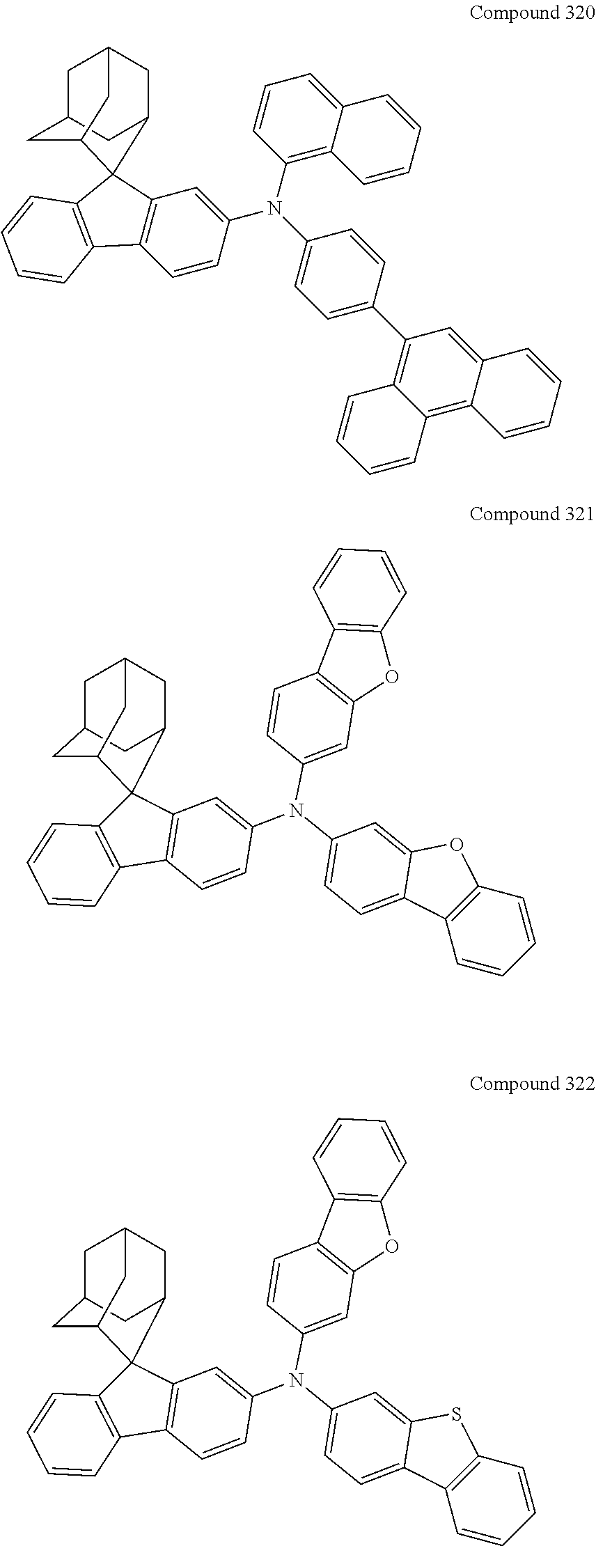
C00348

C00349
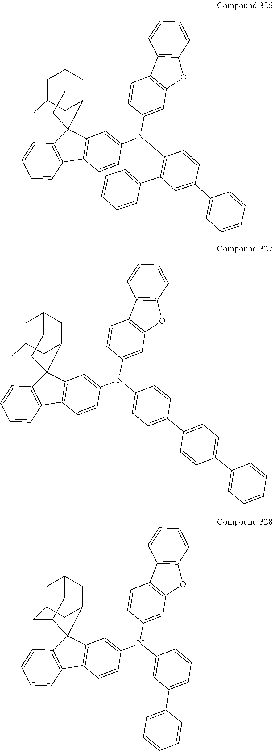
C00350

C00351

C00352
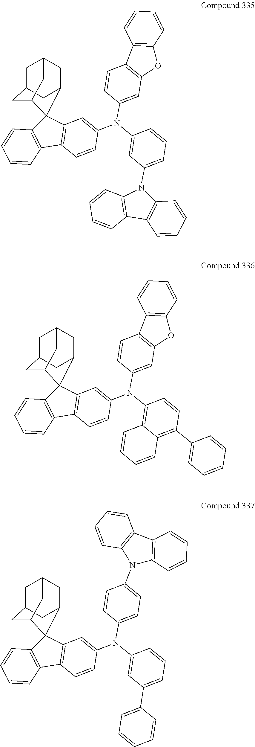
C00353
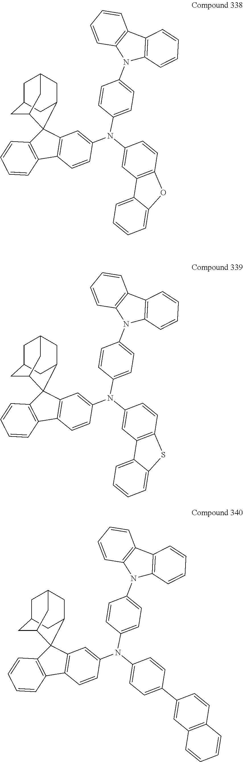
C00354
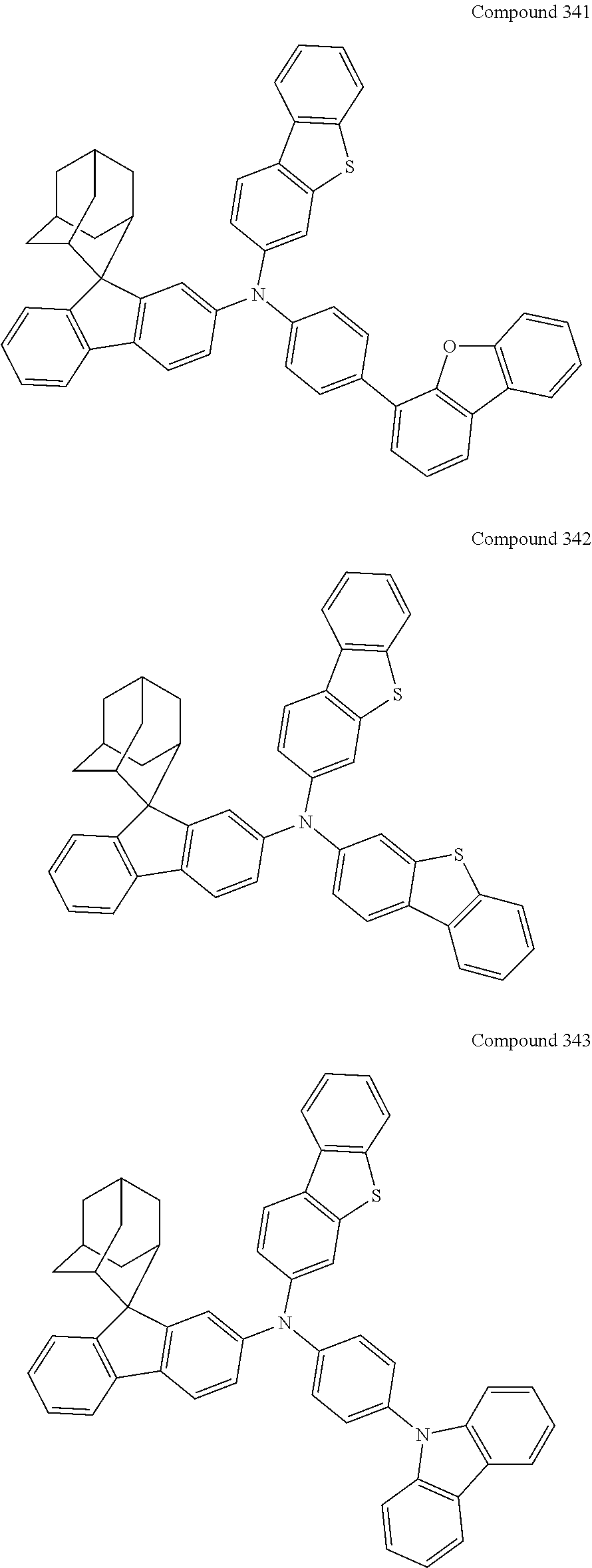
C00355
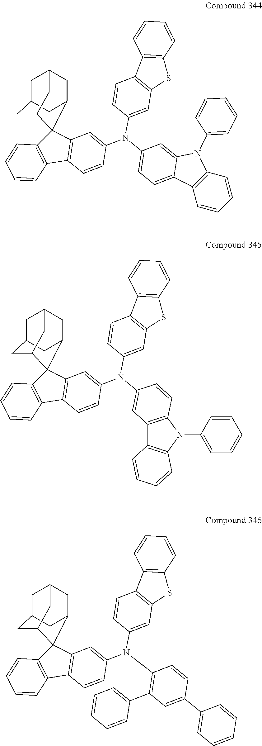
C00356

C00357
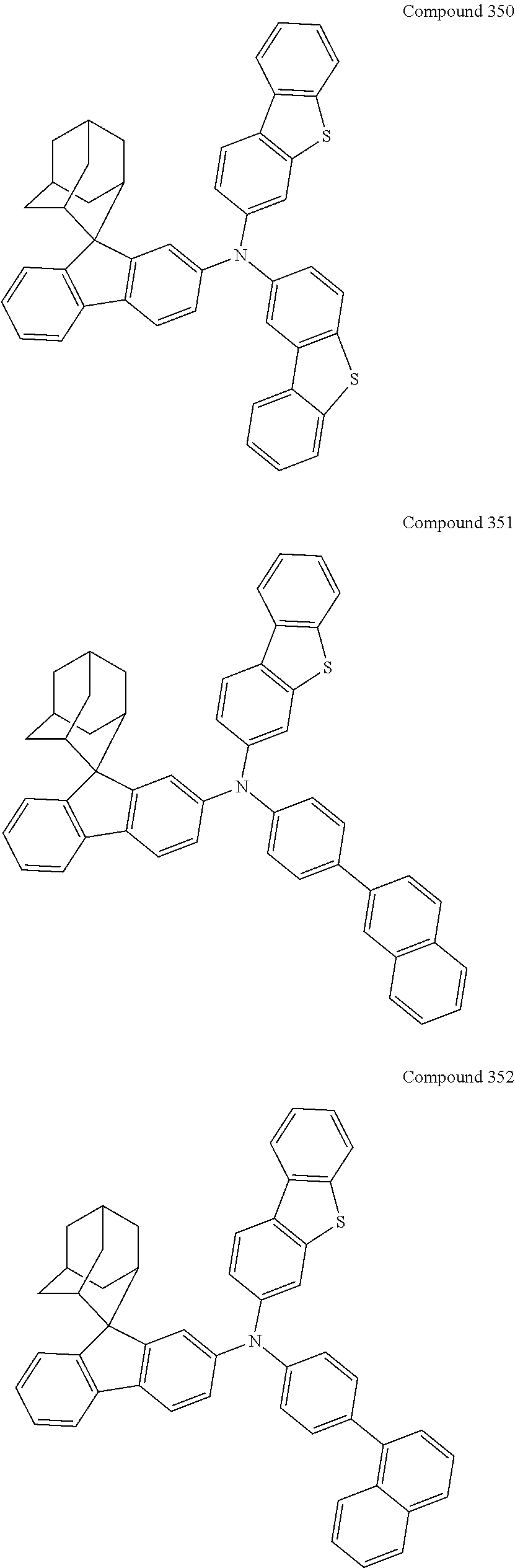
C00358
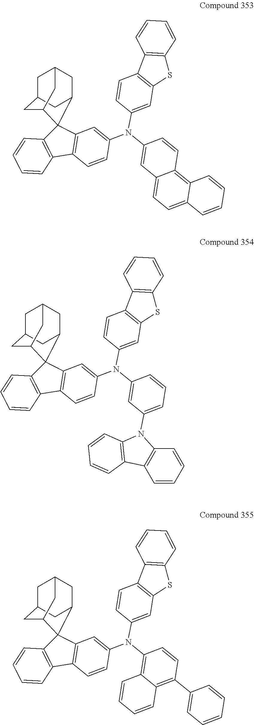
C00359
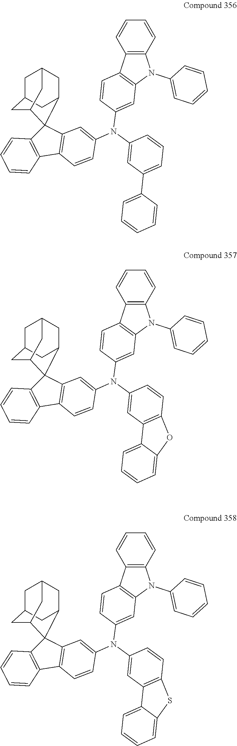
C00360

C00361
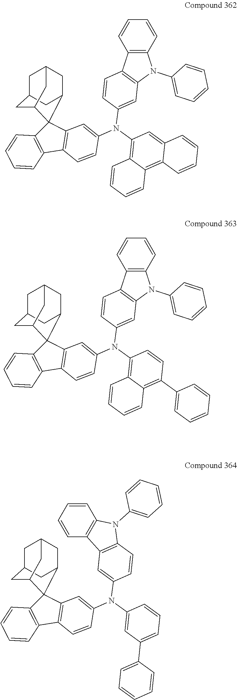
C00362
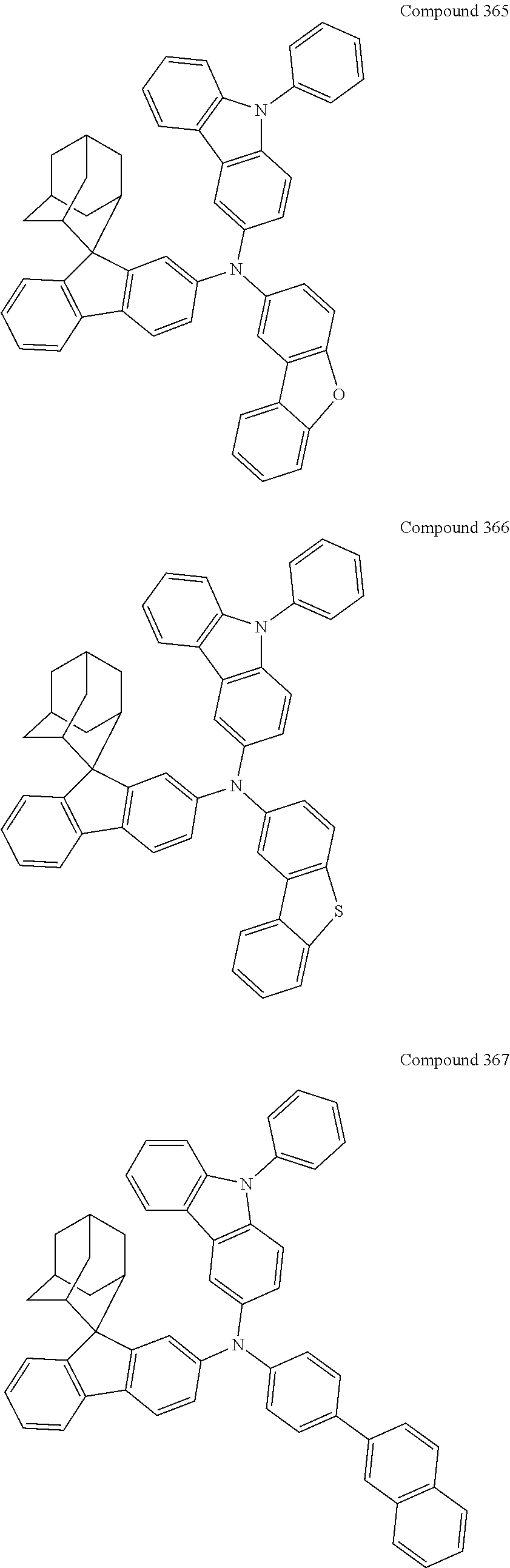
C00363
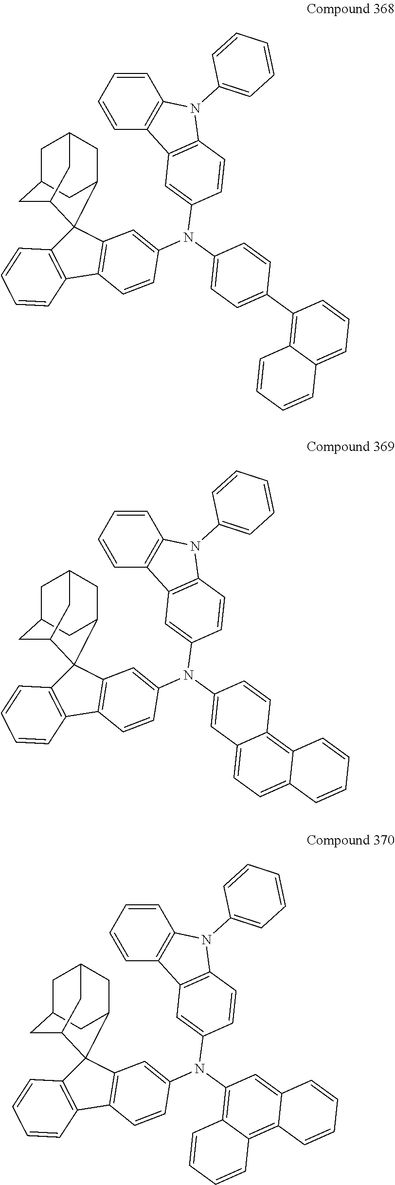
C00364
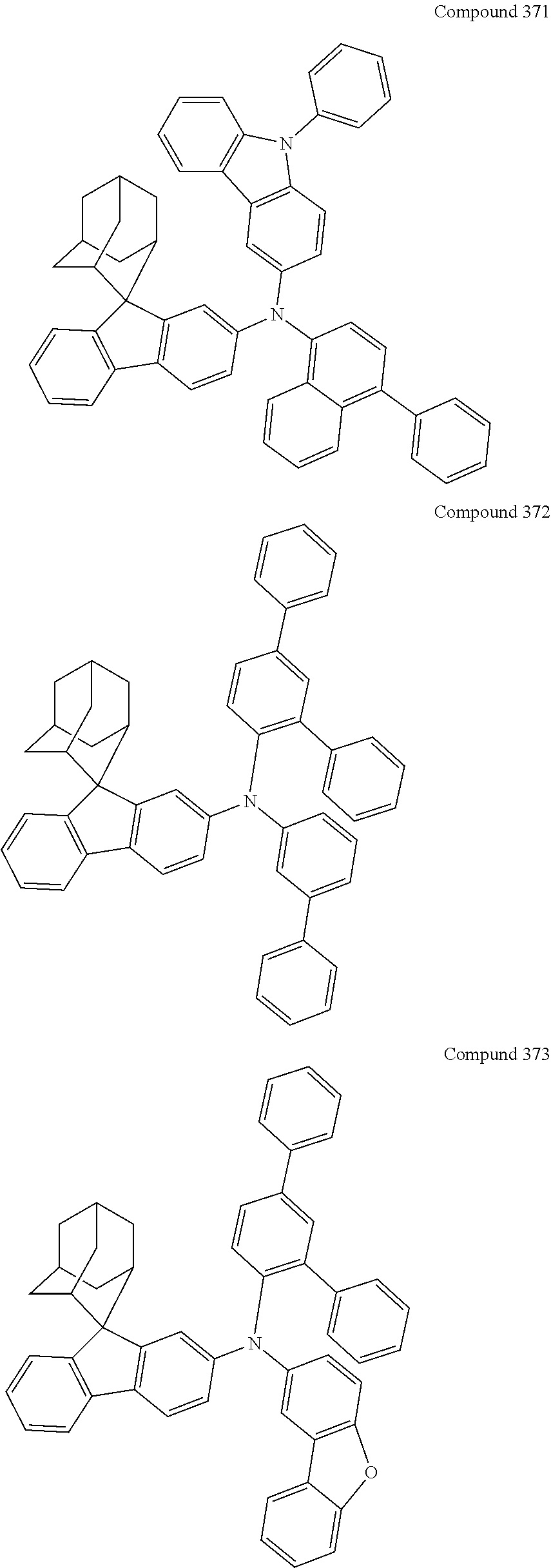
C00365
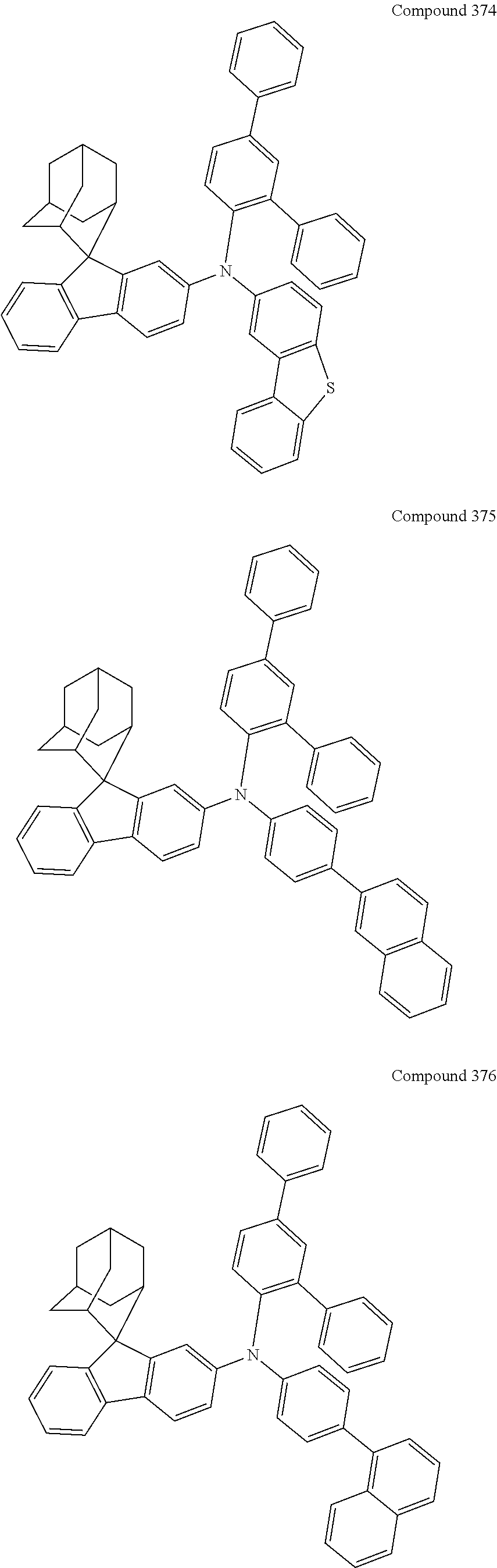
C00366
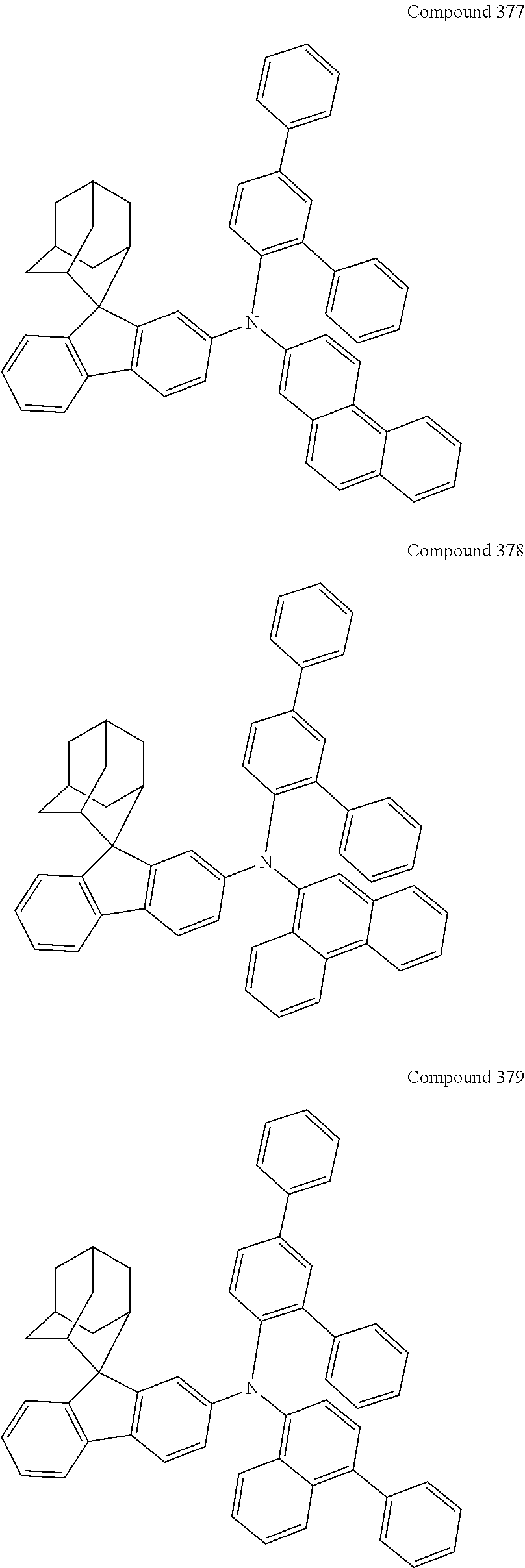
C00367
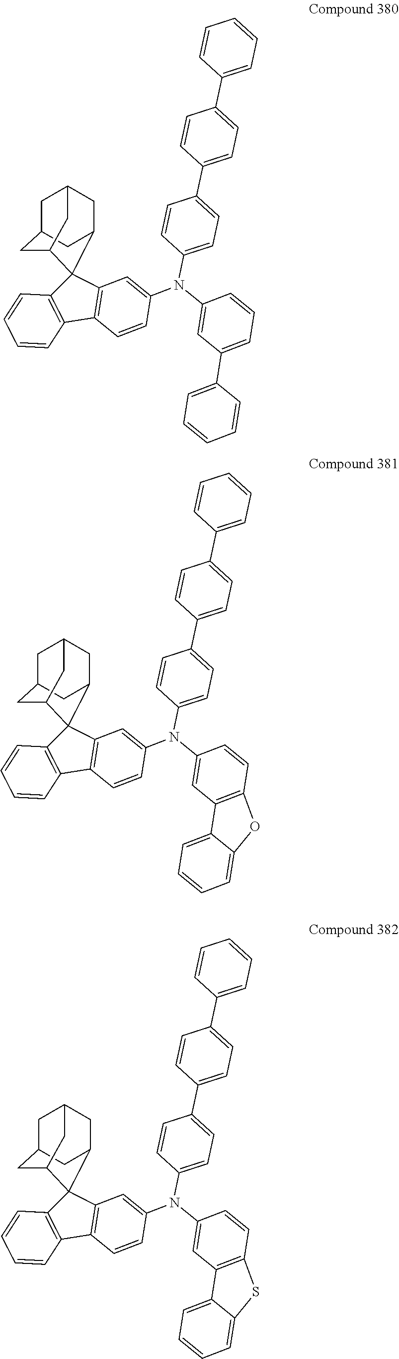
C00368
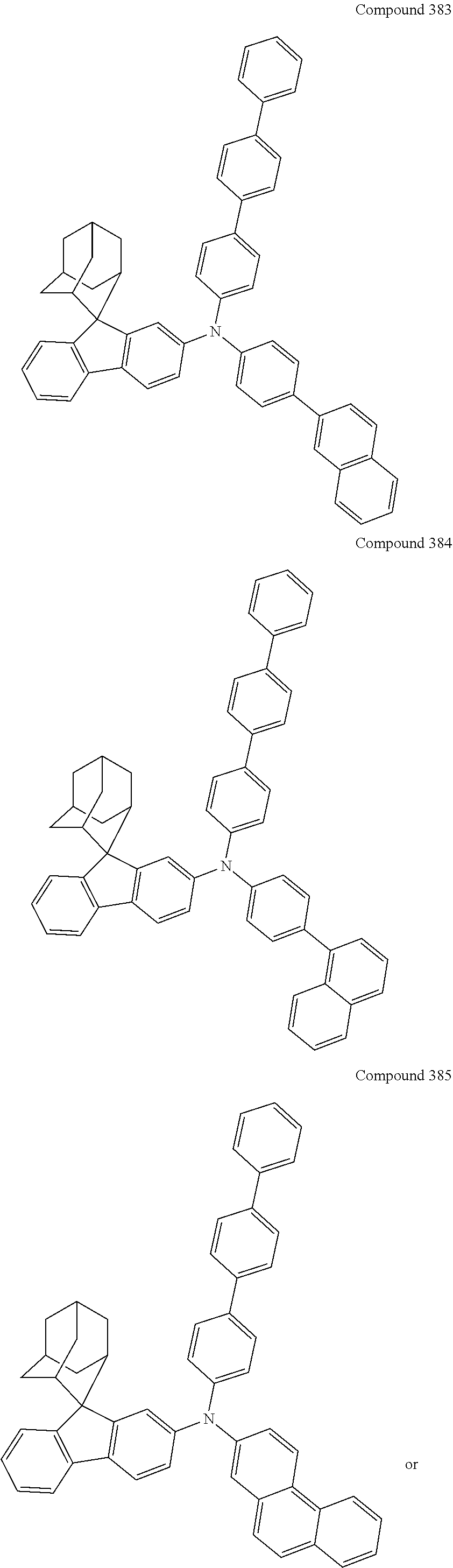
C00369
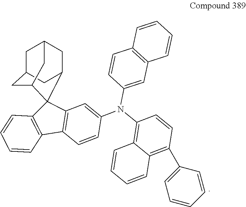
D00000
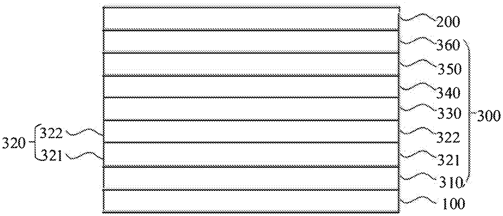
D00001
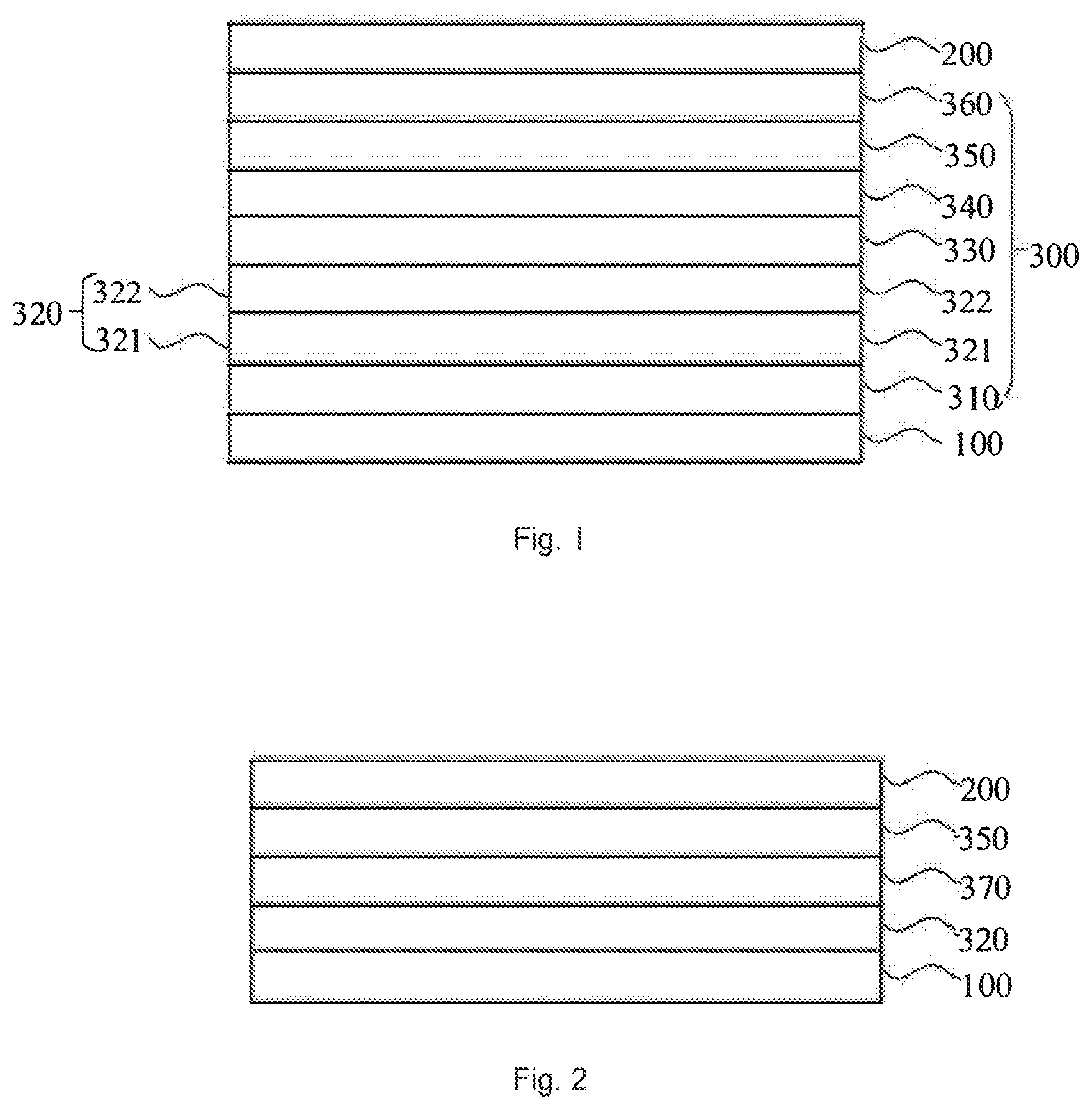
XML
uspto.report is an independent third-party trademark research tool that is not affiliated, endorsed, or sponsored by the United States Patent and Trademark Office (USPTO) or any other governmental organization. The information provided by uspto.report is based on publicly available data at the time of writing and is intended for informational purposes only.
While we strive to provide accurate and up-to-date information, we do not guarantee the accuracy, completeness, reliability, or suitability of the information displayed on this site. The use of this site is at your own risk. Any reliance you place on such information is therefore strictly at your own risk.
All official trademark data, including owner information, should be verified by visiting the official USPTO website at www.uspto.gov. This site is not intended to replace professional legal advice and should not be used as a substitute for consulting with a legal professional who is knowledgeable about trademark law.