Carbon dioxide adsorber for aircraft
Bartosz , et al. April 20, 2
U.S. patent number 10,981,655 [Application Number 16/198,014] was granted by the patent office on 2021-04-20 for carbon dioxide adsorber for aircraft. This patent grant is currently assigned to HAMILTON SUNDSTRAND CORPORATION. The grantee listed for this patent is Hamilton Sundstrand Corporation. Invention is credited to Lance R. Bartosz, Catherine Thibaud.


| United States Patent | 10,981,655 |
| Bartosz , et al. | April 20, 2021 |
Carbon dioxide adsorber for aircraft
Abstract
A system for processing recirculation air recovered from an aircraft cabin includes a mixing chamber and a carbon dioxide removal system. The carbon dioxide removal system has an inlet for recovered recirculation air from the aircraft cabin, an outlet to the mixing chamber; at least two assemblies of carbon dioxide sorbent that are thermally linked, a CO.sub.2 outlet valve; and a controller for managing desorption of carbon dioxide from the sorbent depending on aircraft status. The mixing chamber has an inlet from the carbon dioxide removal system, an inlet from an environmental control system, and an outlet connected to the aircraft cabin.
| Inventors: | Bartosz; Lance R. (Granby, MA), Thibaud; Catherine (Cork, IE) | ||||||||||
|---|---|---|---|---|---|---|---|---|---|---|---|
| Applicant: |
|
||||||||||
| Assignee: | HAMILTON SUNDSTRAND CORPORATION
(Charlotte, NC) |
||||||||||
| Family ID: | 1000005498669 | ||||||||||
| Appl. No.: | 16/198,014 | ||||||||||
| Filed: | November 21, 2018 |
Prior Publication Data
| Document Identifier | Publication Date | |
|---|---|---|
| US 20200156796 A1 | May 21, 2020 | |
| Current U.S. Class: | 1/1 |
| Current CPC Class: | B64D 13/06 (20130101); B01D 53/047 (20130101); B01D 2253/10 (20130101); B64D 2013/0688 (20130101); B64D 2013/0637 (20130101); B01D 2259/4575 (20130101); B01D 2257/504 (20130101) |
| Current International Class: | B01D 53/04 (20060101); B01D 53/047 (20060101); B64D 13/06 (20060101) |
| Field of Search: | ;95/96,114,115,139,148 ;96/121,126 ;423/230 |
References Cited [Referenced By]
U.S. Patent Documents
| 3734293 | May 1973 | Biskis |
| 3738084 | June 1973 | Simonet |
| 4786294 | November 1988 | Jonqueres et al. |
| 5516330 | May 1996 | Dechow |
| 5642729 | July 1997 | Cassidy |
| 5695396 | December 1997 | Markwart |
| 6364938 | April 2002 | Birbara et al. |
| 6709483 | March 2004 | Hodgson, Jr. |
| 6755892 | June 2004 | Nalette et al. |
| 7736416 | June 2010 | Nalette et al. |
| 9341408 | May 2016 | Fleming, Jr. et al. |
| 9597629 | March 2017 | Matthias et al. |
| 9789436 | October 2017 | Meirav et al. |
| 10017257 | July 2018 | Ludvik et al. |
| 10046266 | August 2018 | Meirav et al. |
| 2005/0199124 | September 2005 | Little |
| 2012/0006193 | January 2012 | Roychoudhury et al. |
| 2012/0160098 | June 2012 | Papale |
| 2012/0160099 | June 2012 | Shoji |
| 2014/0161698 | June 2014 | Klimpel |
| 2017/0239609 | August 2017 | Luisman et al. |
| 2018/0050322 | February 2018 | Kimura et al. |
| 2019/0039047 | February 2019 | Kimura |
| 2020/0009533 | January 2020 | Space |
| 016546 | May 2012 | EA | |||
| DP 0332390 | Sep 1989 | EP | |||
| 1964601 | Sep 2008 | EP | |||
| 3090950 | Nov 2016 | EP | |||
| 2014233690 | Dec 2014 | JP | |||
| 9817388 | Apr 1998 | WO | |||
| 2018156020 | Aug 2018 | WO | |||
Other References
|
European Search Report for European Application No. 19209954.7; Application Filing Date Nov. 19, 2019; dated Feb. 26, 2020, 7 pages. cited by applicant. |
Primary Examiner: Lawrence, Jr.; Frank M
Attorney, Agent or Firm: Cantor Colburn LLP
Claims
What is claimed is:
1. A system for processing recirculation air recovered from an aircraft cabin comprising: a mixing chamber and a carbon dioxide removal system, wherein the carbon dioxide removal system has an inlet for recovered recirculation air from the aircraft cabin, at least two assemblies of carbon dioxide sorbent that are thermally linked; an outlet to the mixing chamber; a CO.sub.2 outlet valve and a controller for managing desorption of carbon dioxide from the sorbent depending on aircraft status, and further wherein the mixing chamber has an inlet from the carbon dioxide removal system, an inlet from an environmental control system, and an outlet connected to the aircraft cabin.
2. The system of claim 1, wherein the assemblies are thermally linked by a thermoelectric device.
3. The system of claim 1, wherein the assemblies are passively thermally linked.
4. The system of claim 1, wherein the assemblies are interleaved.
5. The system of claim 1, wherein the carbon dioxide sorbent comprises a solid amine sorbent.
6. The system of claim 1, further comprising an ambient outlet valve.
7. A method for processing recovered recirculation air discharged from an aircraft cabin comprising: supplying recovered recirculation air from the aircraft cabin to a carbon dioxide removal system having at least two thermally linked assemblies of carbon dioxide sorbent; removing carbon dioxide from the recovered recirculation air to form processed recirculation air; removing carbon dioxide from the carbon dioxide sorbent; mixing the processed recirculation air with conditioned fresh air; and sending the mixture to the aircraft cabin, wherein the removal of carbon dioxide from the carbon dioxide sorbent is by reduced pressure, elevated temperature or both and the method of removal is determined the by aircraft status.
8. The method of claim 7, wherein reduced pressure is provided by ambient air when the ambient air has a pressure less than the cabin air.
9. The method of claim 7, wherein the at least two thermally linked assemblies are interleaved.
10. The method of claim 7, wherein the at least two assemblies of carbon dioxide sorbent comprise a solid amine sorbent.
Description
BACKGROUND
Exemplary embodiments pertain to the art of systems and methods for removing carbon dioxide from recirculation air discharged from an aircraft cabin.
The air conditioning system for a modern passenger aircraft includes an air conditioning unit which is supplied with compressed process air from a compressor or bled off from an engine or an auxiliary power unit of the aircraft. Cooled air leaving the air conditioning unit is supplied to a mixing chamber where it is mixed with recirculation air from the aircraft cabin to result in mixed air. The mixed air is supplied to the aircraft cabin.
The carbon dioxide (CO.sub.2) content of the recirculated air increases due to human respiration. The carbon dioxide content of the air returned to the aircraft cabin can be reduced by mixing with fresh air from the air conditioning unit, by adsorption, or by a combination thereof. While currently available systems are adequate, there is a need for more efficient systems and methods for reducing the carbon dioxide content of the recirculated air and the air returned to the aircraft cabin.
BRIEF DESCRIPTION
Disclosed is a system for processing recirculation air recovered from an aircraft cabin comprising a mixing chamber and a carbon dioxide removal system, wherein the carbon dioxide removal system has an inlet for recovered recirculation air from the aircraft cabin, an outlet to the mixing chamber; at least two assemblies of carbon dioxide sorbent that are thermally linked, a CO.sub.2 outlet valve; and a controller for managing desorption of carbon dioxide from the sorbent depending on aircraft status and further wherein the mixing chamber has an inlet from the carbon dioxide removal system, an inlet from an environmental control system, and an outlet connected to the aircraft cabin.
Also disclosed is a method for processing recirculation air recovered from an aircraft cabin comprising supplying recovered recirculation air from the aircraft cabin to a carbon dioxide removal system having at least two thermally linked assemblies of carbon dioxide sorbent; removing carbon dioxide from the recovered recirculation air to form processed recirculation air, removing carbon dioxide from the carbon dioxide sorbent; mixing the processed recirculation air with conditioned fresh air and sending the mixture to the aircraft cabin, wherein the removal of carbon dioxide from the carbon dioxide sorbent is by reduced pressure, elevated temperature or both and is determined by the aircraft status.
BRIEF DESCRIPTION OF THE DRAWINGS
The following descriptions should not be considered limiting in any way. With reference to the accompanying drawings, like elements are numbered alike:
FIGS. 1 to 6 are schematics of recirculation air processing systems.
DETAILED DESCRIPTION
A detailed description of one or more embodiments of the disclosed apparatus and method are presented herein by way of exemplification and not limitation with reference to the Figures.
Carbon dioxide removal from recovered recirculated aircraft cabin air may involve the use of a carbon dioxide sorbent. The carbon dioxide sorbent can be regenerated and used repeatedly. Regeneration can involve exposing the carbon dioxide sorbent to reduced pressure, elevated temperature or both. By using a controller to manage the regeneration conditions efficiency can be maximized depending upon the aircraft status. For example, at cruising conditions (elevated altitude), ambient pressure is less than the pressure of the aircraft cabin and pressurized areas of the aircraft. This low ambient pressure can be employed to provide reduced pressure for regeneration. When the aircraft is on the ground or the ambient pressure is too high for sufficient regeneration alone, elevated temperature can be used for regeneration. The controller monitors the ambient pressure and manages the regeneration method. When the regeneration method involves elevated temperature the thermal linking of the two sorbent beds helps to recover energy from the carbon dioxide adsorption in one bed and use it to facilitate the carbon dioxide desorption in the second bed. Through the use of a controller in combination with a carbon dioxide removal system the need for fresh air from the engine (via the air conditioning system) is reduced. Fresh air is typically provided as bleed air from the engines and the air is conditioned to achieve the desired temperature and pressure. Systems that reduce the demand for fresh air from the air conditioning system offer an opportunity to reduce overall aircraft energy consumption as compared with the current state of art.
According to the systems and methods described herein, process streams include cabin air. These process streams contain carbon dioxide that can be removed from the process stream.
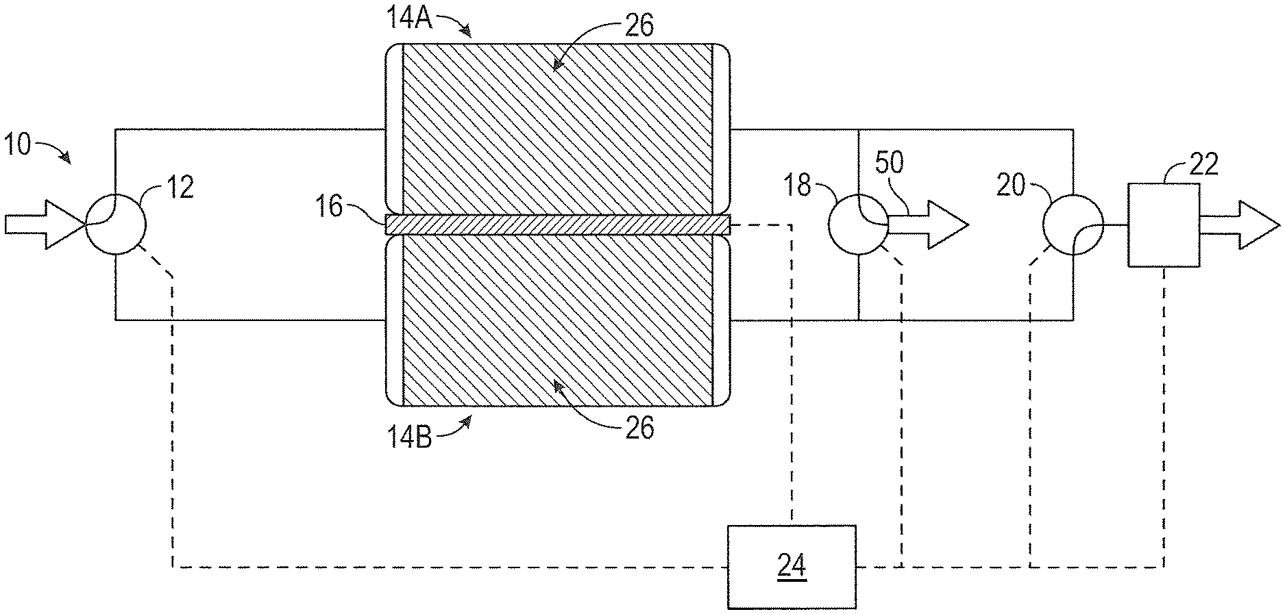
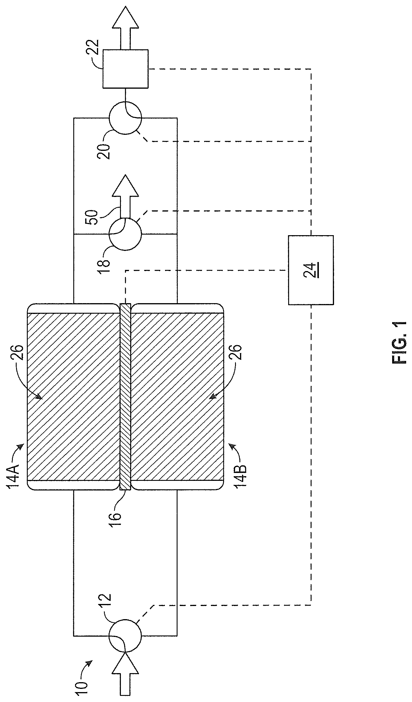
FIG. 1 illustrates one embodiment of carbon dioxide (CO.sub.2) removal system 10. CO.sub.2 removal system 10 includes inlet valve 12, first sorbent assembly 14A, second sorbent assembly 14B, heat exchange system 16, gas stream outlet valve 18, CO.sub.2 outlet valve 20, and controller 24. A process stream enters CO.sub.2 removal system 10 via inlet valve 12. The process stream is recovered recirculation air from an aircraft cabin. The process stream can be delivered to CO.sub.2 removal system 10 by pump or other means. Inlet valve 12 allows the process air stream to communicate with first sorbent assembly 14A and second sorbent assembly 14B. Depending on the position of inlet valve 12, the process stream is directed to first sorbent assembly 14A or second sorbent assembly 14B. As shown in FIG. 1, inlet valve 12 is positioned so that the process stream is directed to first sorbent assembly 14A. The process stream contains CO.sub.2. Exemplary incoming process streams for CO.sub.2 removal system 10 contain between about 0.5% CO.sub.2 and about 1% CO.sub.2 by volume.
First sorbent assembly 14A includes a solid amine sorbent. Solid amine sorbent 26 is contained within first sorbent assembly 14A. Solid amine sorbent 26 is a regenerable CO.sub.2 sorbent. In one exemplary embodiment, solid amine sorbent 26 includes one of the amine sorbents described in U.S. Pat. No. 6,364,938, which is hereby incorporated by reference in its entirety. Under certain conditions, solid amine sorbent 26 adsorbs CO.sub.2 from a process stream flowing through first sorbent assembly 14A and in contact with solid amine sorbent 26. In this case, CO.sub.2 is removed from the process stream flowing through first sorbent assembly 14A when it is adsorbed by solid amine sorbent 26. Under other conditions, solid amine sorbent 26 desorbs CO.sub.2 to a process stream flowing through first sorbent assembly 14A and in contact with solid amine sorbent 26. Here, CO.sub.2 from solid amine sorbent 26 is taken up by the process stream and carried away from first sorbent assembly 14A. The temperature of and pressure surrounding solid amine sorbent 26 determines whether solid amine sorbent 26 adsorbs CO.sub.2 or desorbs CO.sub.2. Second sorbent assembly 14B is generally located near and can have identical or similar size and dimensions to first sorbent assembly 14A. Second sorbent assembly 14B also includes solid amine sorbent 26. First sorbent assembly 14A and second sorbent assembly 14B are designed to generally operate in opposing sorption modes. That is, when first sorbent assembly 14A is adsorbing CO.sub.2, second sorbent assembly 14B is desorbing CO.sub.2. When first sorbent assembly 14A is desorbing CO.sub.2, second sorbent assembly 14B is adsorbing CO.sub.2.
First sorbent assembly 14A and second sorbent assembly 14B are thermally linked by a heat exchange system. In the embodiment illustrated in FIG. 1, the heat exchange system includes thermoelectric device 16. Thermoelectric device 16 is positioned between first sorbent assembly 14A and second sorbent assembly 14B. Thermoelectric devices take advantage of the thermoelectric effect, which describes the direct conversion of temperature differences to electric voltage and vice versa. A thermoelectric device creates a voltage when there is a different temperature on each side. Conversely, when a voltage is applied to a thermoelectric device, it creates a temperature difference (i.e. one side is heated while the other side is cooled). For example, when a voltage is applied to thermoelectric device 16, one side of thermoelectric device 16 generates heat and heats adjacent first sorbent assembly 14A. At the same time, the other side of thermoelectric device 16 is cooled and cools adjacent second sorbent assembly 14B. The voltage is reversed to cool first sorbent assembly 14A and heat second sorbent assembly 14B. Thermoelectric device 16 provides an efficient means of temperature adjustment without requiring a significant amount of power. While the heat exchange system can take forms other than a thermoelectric device, CO.sub.2 removal system 10 will be described in greater detail where the heat exchange system is a thermoelectric device.
Gas stream outlet valve 18 communicates with first sorbent assembly 14A and second sorbent assembly 14B. Gas stream outlet valve 18 allows a process stream 50 that has passed through a CO.sub.2 adsorbing bed (first sorbent assembly 14A or second sorbent assembly 14B) to exit CO.sub.2 removal system 10 and, as shown in FIG. 6, enter the mixing chamber 40 via inlet 35 where it is combined with a process stream 33 from the environmental control system via inlet 37 and the combined process stream 45 leaves the mixing chamber via outlet 39 and is delivered to the aircraft cabin. At a given time, gas stream outlet valve 18 communicates with the CO.sub.2 adsorbing bed but not the CO.sub.2 desorbing bed.
CO.sub.2 outlet valve 20 also communicates with first sorbent assembly 14A and second sorbent assembly 14B. CO.sub.2 outlet valve 20 allows a process stream that has passed through a CO.sub.2 desorbing bed (first sorbent assembly 14A or second sorbent assembly 14B) to exit CO.sub.2 removal system 10. The process stream exiting CO.sub.2 removal system 10 through CO.sub.2 outlet valve 20 generally has a higher concentration than the process stream entering CO.sub.2 removal system 10 through inlet valve 12. The process stream exiting through CO.sub.2 outlet valve may communicate directly with the ambient environment or may pass through an ambient outlet valve.
In one embodiment of CO.sub.2 removal system 10, CO.sub.2 outlet valve 20 is positioned between first sorbent assembly 14A, second sorbent assembly 14B and the ambient outlet valve 22. Ambient outlet valve 22 opens to the ambient environment when the ambient pressure is less than that of the pressurized cabin and CO.sub.2 removal system and reduces pressure on the outlet side of first sorbent assembly 14A and second sorbent assembly 14B to increase the rate of CO.sub.2 removal (desorption) from the desorbing bed. As discussed in greater detail below, ambient outlet valve 22 allows CO.sub.2 removal system 10 to produce an exiting process stream rich in CO.sub.2. The ambient outlet valve is controlled by controller 24.
In the embodiment of CO.sub.2 removal system 10 shown in FIGS. 1 and 2, controller 24 communicates with inlet valve 12, thermoelectric device 16, gas stream outlet valve 18, CO.sub.2 outlet valve 20 and ambient outlet valve 22. Controller 24 controls the valves and heat exchange system of CO.sub.2 removal system 10 to cycle the first sorbent assembly 14A and second sorbent assembly 14B between CO.sub.2 adsorption and CO.sub.2 desorption. The role of controller 24 and how the valves, heat exchange system and pump operate during the CO.sub.2 removal process are discussed in additional detail below.
As shown in FIGS. 1 and 2, first sorbent assembly 14A and second sorbent assembly 14B may be thermally linked by thermoelectric device 16. During operation of CO.sub.2 removal system 10, a voltage may be applied to thermoelectric device 16 such that the CO.sub.2 adsorbing bed is cooled while the CO.sub.2 desorbing bed is heated. Thermoelectric device 16 generally maintains the CO.sub.2 desorbing bed at a higher temperature than the CO.sub.2 adsorbing bed. The controller 24 controls when the desorption is driven by reduced pressure via the ambient outlet valve 22, temperature differential via the thermoelectric device 16, or a combination thereof. The controller 23 can direct the system based on the aircraft status. For example, when cruising at altitude the reduced ambient air pressure can provide reduced pressure to facilitate desorption.
As shown in FIG. 1, CO.sub.2 removal system 10 is operating in a state where first sorbent assembly 14A is the adsorbing bed. A process stream enters CO.sub.2 removal system 10 through inlet valve 12. Inlet valve 12 is positioned to allow the process stream to enter first sorbent assembly 14A. CO.sub.2 is adsorbed to solid amine sorbent 26 in first sorbent assembly 14A. Solid amine sorbent 26 has a defined capacity for CO.sub.2 adsorption. The temperature of solid amine sorbent 26 and the CO.sub.2 pressure within first sorbent assembly 14A determine how much CO.sub.2 can be loaded onto solid amine sorbent 26. As the temperature of solid amine sorbent 26 decreases, the loading capacity for CO.sub.2 adsorption increases. As the partial pressure of CO.sub.2 within first sorbent assembly 14A increases, the loading capacity for CO.sub.2 adsorption also increases. The adsorption of CO.sub.2 by solid amine sorbent 26 is exothermic. Thus, as CO.sub.2 is adsorbed by solid amine sorbent 26, the temperature of solid amine sorbent 26 increases, reducing its capacity to adsorb CO.sub.2 until it reaches an equilibrium state where the temperature of solid amine sorbent 26 prevents further CO.sub.2 adsorption. Thermoelectric device 16 may operate to cool first sorbent assembly 14A and, hence, solid amine sorbent 26 contained within first sorbent assembly 14A. By actively cooling first sorbent assembly 14A, the CO.sub.2 loading capacity of solid amine sorbent 26 may be increased allowing additional CO.sub.2 adsorption within first sorbent assembly 14A. Since first sorbent assembly 14A is cooled by thermoelectric device 16 as CO.sub.2 is adsorbed by solid amine sorbent 26, a temperature-related pressure increase is generally not observed during CO.sub.2 adsorption. After passing through first sorbent assembly 14A, the process stream 30 is removed from CO.sub.2 removal system 10 via gas stream outlet valve 18. The process stream removed through gas stream outlet valve 18 has a lower amount of CO.sub.2 than the process stream that entered CO.sub.2 removal system 10 through inlet valve 12.
At the same time that first sorbent assembly 14A is adsorbing CO.sub.2, second sorbent assembly 14B is desorbing CO.sub.2. Second sorbent assembly 14B includes solid amine sorbent 26 that contains adsorbed CO.sub.2 from an earlier CO.sub.2 adsorption cycle. The desorption of CO.sub.2 by solid amine sorbent 26 is endothermic. As noted above, as the temperature of solid amine sorbent 26 decreases, the loading capacity for CO.sub.2 adsorption increases. Thus, as CO.sub.2 is desorbed by solid amine sorbent 26, the temperature of solid amine sorbent 26 decreases, making it more difficult to desorb CO.sub.2 until it reaches an equilibrium state where the temperature of solid amine sorbent 26 prevents further CO.sub.2 desorption. At the same time that thermoelectric device 16 operates to cool first sorbent assembly 14A, thermoelectric device 16 heats second sorbent assembly 14B. By actively heating second sorbent assembly 14B, the CO.sub.2 loading capacity of solid amine sorbent 26 is decreased making it easier to desorb CO.sub.2 from solid amine sorbent 26 within second sorbent assembly 14B.
Ambient outlet valve 22 operates to reduce the partial pressure of CO.sub.2 at second sorbent assembly 14B when the ambient air pressure is less than the pressure of the CO.sub.2 removal system 10 (which is typically equivalent to the pressure of the aircraft cabin). As noted above, as the partial pressure of CO.sub.2 within second sorbent assembly 14B increases, the loading capacity for CO.sub.2 adsorption also increases. Ambient outlet valve 22 communicates with the CO.sub.2 desorbing bed--second sorbent assembly 14B in the system shown in FIG. 1. Thus, as ambient outlet valve 22 opens to allow fluid to move away from CO.sub.2 removal system 10, the partial pressure of CO.sub.2 at second sorbent assembly 14B is reduced, thereby reducing the CO.sub.2 loading capacity of solid amine sorbent 26 within second sorbent assembly 14B. Since the CO.sub.2 loading capacity of the desorbing bed is reduced, CO.sub.2 present in second sorbent assembly 14B is more easily removed from solid amine sorbent 26. A process stream containing high levels of CO.sub.2 is removed from second sorbent assembly 14B and exits CO.sub.2 removal system 10 via CO.sub.2 outlet valve 20. The process stream removed through CO.sub.2 outlet valve 20 has a higher amount of CO.sub.2 than the process stream that entered CO.sub.2 removal system 10 through inlet valve 12. In exemplary embodiments the removed process stream contains at least about 90% CO.sub.2 by volume. In more exemplary embodiments the removed process stream contains at least about 95% CO.sub.2 by volume.
FIG. 2 illustrates the CO.sub.2 removal system 10 of FIG. 1 where the CO.sub.2 adsorbing and CO.sub.2 desorbing beds are reversed. Having adsorbed CO.sub.2 according to the description above and shown in FIG. 1, first sorbent assembly 14A is now desorbing CO.sub.2 in FIG. 2. Likewise, having given up its adsorbed CO.sub.2 according to the description above and shown in FIG. 1, second sorbent assembly 14B is now adsorbing CO.sub.2 in FIG. 2. Controller 24 adjusts inlet valve 12, thermoelectric device 16, gas stream outlet valve 18, CO.sub.2 outlet valve 20 and ambient outlet valve 22 so that the process and output streams are flowing through the proper sorbent assemblies. Inlet valve 12 is positioned to allow the process stream to enter second sorbent assembly 14B. Thermoelectric device 16 operates to cool second sorbent assembly 14B and heat first sorbent assembly 14A. After passing through second sorbent assembly 14B, the process stream is removed from CO.sub.2 removal system 10 via gas stream outlet valve 18. Ambient outlet valve 22 operates to reduce the partial pressure of CO.sub.2 at first sorbent assembly 14A. A process stream containing high levels of CO.sub.2 is removed from first sorbent assembly 14A and exits CO.sub.2 removal system 10 via CO.sub.2 outlet valve 20.
The descriptions of the CO.sub.2 adsorbing bed (first sorbent assembly 14A) and the CO.sub.2 desorbing bed (second sorbent assembly 14B) in FIG. 1 above illustrate a snapshot of adsorption and desorption. Between adsorption and desorption modes, each bed can enter a transitional state. For example, in the case of the adsorbing bed, once solid amine sorbent 26 of first sorbent assembly 14A has reached its CO.sub.2 adsorption capacity, first sorbent assembly 14A is no longer adsorbing CO.sub.2. First sorbent assembly 14A can now be heated to increase the CO.sub.2 partial pressure within first sorbent assembly 14A. By heating first sorbent assembly 14A, the CO.sub.2 loading capacity of solid amine sorbent 26 within first sorbent assembly 14A is reduced, preparing it for the CO.sub.2 desorption cycle. The voltage applied to thermoelectric device 16 is reversed to accommodate the heating change in this transitional state. At the same time, solid amine sorbent 26 of second sorbent assembly 14B has released all of the CO.sub.2 it is capable of desorbing to the low pressure process stream. Second sorbent assembly 14B can now be cooled to increase the CO.sub.2 loading capacity of solid amine sorbent 26 within second sorbent assembly 14B. By cooling second sorbent assembly 14B, the CO.sub.2 loading capacity of solid amine sorbent 26 within second sorbent assembly 14B is increased, preparing it for the CO.sub.2 adsorption cycle.
The transitional states described above can be isolated from the adsorbing and desorbing operations or integrated within the adsorbing and desorbing operations. For example, first sorbent assembly 14A can be isolated from CO.sub.2 removal system 10 using valves 12, 18 and 20 to prevent process stream flow through first sorbent assembly 14A. First sorbent assembly 14A can then be heated to increase the pressure within first sorbent assembly 14A. Once first sorbent assembly 14A has been heated to an appropriate temperature, valves 12, 18 and 20 can be positioned to allow first sorbent assembly 14A to transition to the desorption mode. Alternatively, first sorbent assembly 14A can transition to the desorption mode followed by heating and application of negative pressure to increase the rate of CO.sub.2 desorption. Whether the transitional states are isolated or integrated within CO.sub.2 removal system 10 will depend on application or efficiency requirements and design considerations for CO.sub.2 removal system 10.
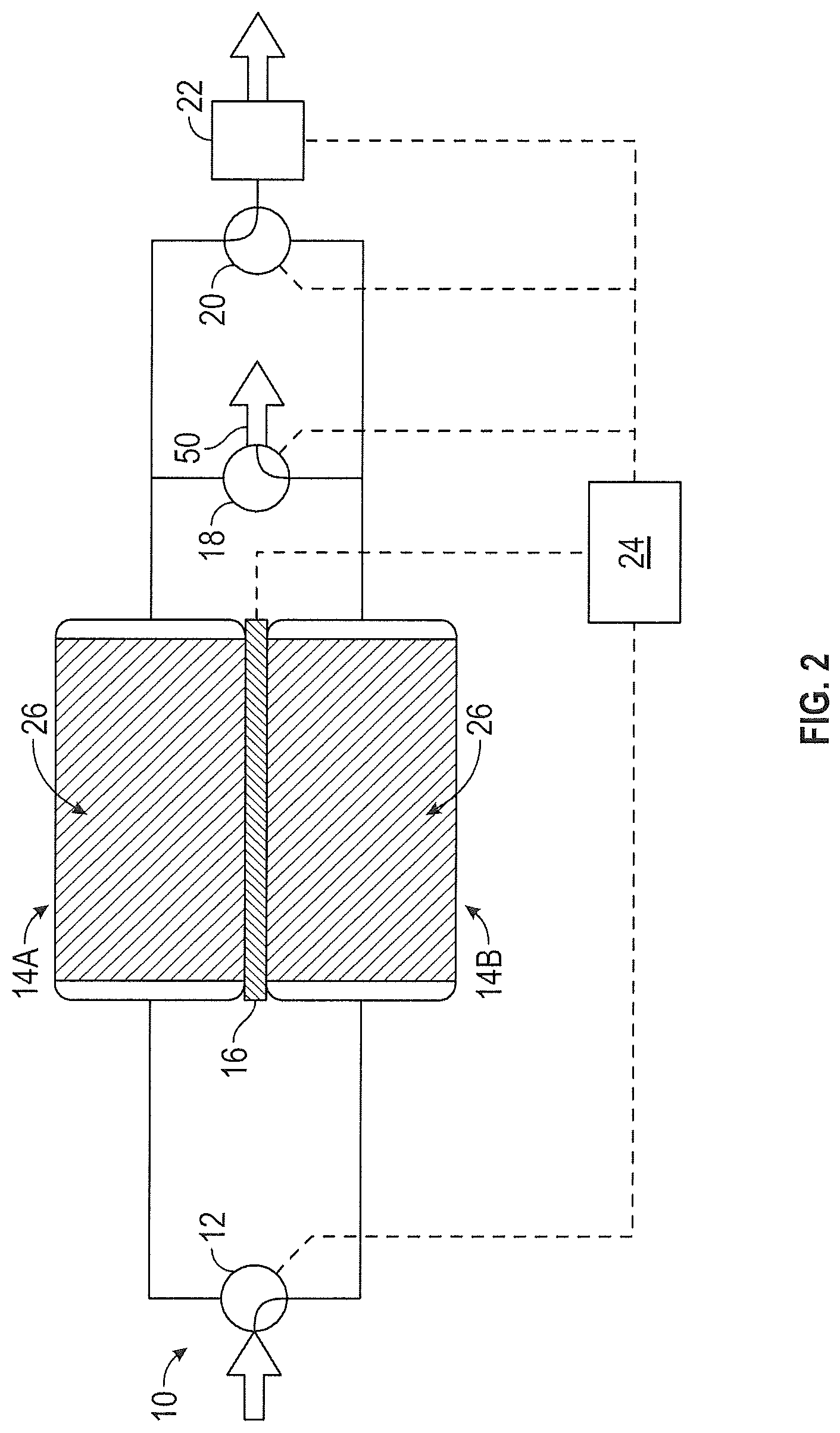
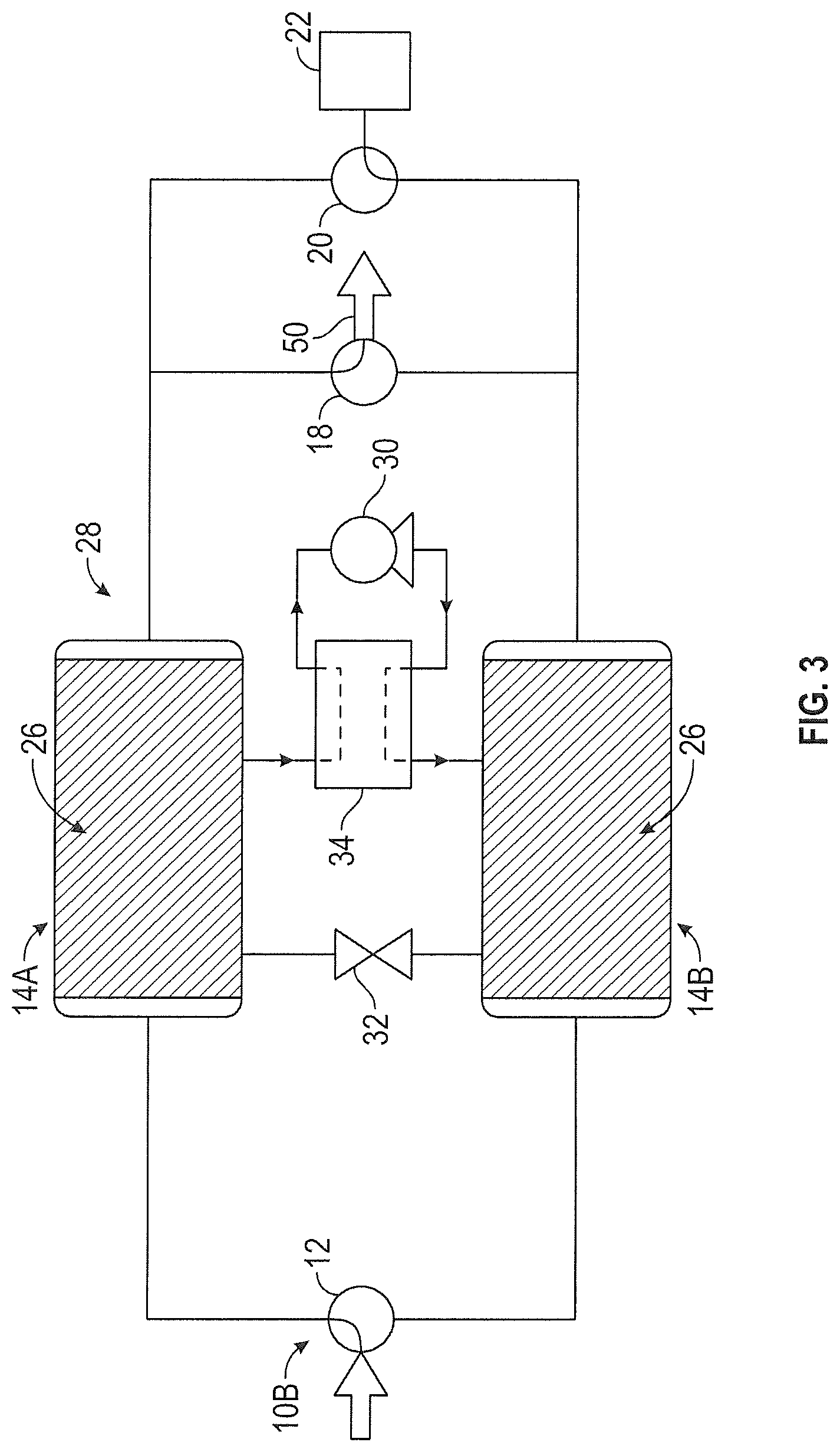
FIG. 3 illustrates an alternative embodiment of a CO.sub.2 removal system (CO.sub.2 removal system 10B) in which thermoelectric device 16 has been replaced by heat exchange system 28. In one embodiment, heat exchange system 28 operates as a vapor-compression refrigeration cycle. Heat exchange system 28 includes heat pump 30, expansion device 32 and reversing valve 34. First sorbent assembly 14A is adsorbing CO.sub.2 and functions as the evaporator. Heat is transferred from first sorbent assembly 14A to a refrigerant within heat exchange system 28. The refrigerant is delivered to reversing valve 34, where it is directed to heat pump 30. Heat pump 30 functions as the compressor and delivers the refrigerant to second sorbent assembly 14B. Second sorbent assembly 14B is desorbing CO.sub.2 and functions as the condenser. Heat is transferred from the refrigerant to second sorbent assembly 14B. The refrigerant is delivered to expansion device 32 where it expands. The refrigerant is then delivered to first sorbent assembly 14A to repeat the process. The flow of refrigerant is reversed using reversing valve 34 when the adsorbing and desorbing beds are cycled. FIG. 4 illustrates CO.sub.2 removal system 10B where second sorbent assembly 14B is adsorbing CO.sub.2 and first sorbent assembly 14A is desorbing CO.sub.2. Here, second sorbent assembly 14B functions as the evaporator and first sorbent assembly 14A functions as the condenser. Reversing valve 34 can adjust the flow of refrigerant within heat exchange system 28 so that heat pump 30 only pumps refrigerant in a single direction.
FIG. 5 shows an embodiment wherein the first sorbent assembly 14A and the second sorbent assembly 14B are thermally linked passively by interleaving the two sorbent assemblies.
A wide range of temperatures are suitable for first sorbent assembly 14A and second sorbent assembly 14B during the CO.sub.2 removal process. CO.sub.2 removal system 10 generally operates most effectively at temperatures between about 15.degree. C. and about 80.degree. C. In an exemplary embodiment, the desorbing bed is heated to a temperature between about 35.degree. C. and about 80.degree. C. while the adsorbing bed is cooled to a temperature between about 15.degree. C. and about 25.degree. C. In one exemplary embodiment, the desorbing bed is heated to a temperature between about 55.degree. C. and about 80.degree. C. Due to the energy required to actively heat and cool first sorbent assembly 14A and second sorbent assembly 14B, keeping the temperature difference between the desorbing bed and the adsorbing bed small is desirable. Determination of ideal temperature differences depends upon the particular application CO.sub.2 removal system 10 is designed for in addition to CO.sub.2 removal rate requirements. In exemplary embodiments, the temperature difference between the desorbing bed and the adsorbing bed is between about 10.degree. C. and about 65.degree. C. In one exemplary embodiment, the temperature difference between the desorbing bed and the adsorbing bed is between about 10.degree. C. and about 35.degree. C. The low temperature difference between the desorbing and adsorbing beds generally allows CO.sub.2 removal system 10 to operate with much greater efficiency than liquid amine and molecular sieve systems.
A wide range of pressures can be drawn on the desorbing bed. CO.sub.2 removal system 10 generally operates most effectively where low ambient pressure generates a low pressure on the desorbing bed between 3.5 kPa (0.5 psi) and 100 kPa (14.5 psi). In an exemplary embodiment, a low pressure of between 20 kPa (3.0 psi) and 55 kPa (8.0 psi) is drawn on the desorbing bed.
CO.sub.2 removal system 10 can employ a wide range of cycle times between bed transitions from CO.sub.2 adsorption to CO.sub.2 desorption and vice versa. As is the case with the temperature difference between the adsorbing bed and the desorbing bed, determination of ideal cycle times depends upon the particular application CO.sub.2 removal system 10 is designed for in addition to CO.sub.2 removal rate requirements. In exemplary embodiments, the adsorbing and desorbing beds cycle at an interval no greater than about 30 minutes. In one exemplary embodiment, the adsorbing and desorbing beds cycle at an interval no greater than about 20 minutes.
The term "about" is intended to include the degree of error associated with measurement of the particular quantity based upon the equipment available at the time of filing the application.
The terminology used herein is for the purpose of describing particular embodiments only and is not intended to be limiting of the present disclosure. As used herein, the singular forms "a", "an" and "the" are intended to include the plural forms as well, unless the context clearly indicates otherwise. It will be further understood that the terms "comprises" and/or "comprising," when used in this specification, specify the presence of stated features, integers, steps, operations, elements, and/or components, but do not preclude the presence or addition of one or more other features, integers, steps, operations, element components, and/or groups thereof.
While the present disclosure has been described with reference to an exemplary embodiment or embodiments, it will be understood by those skilled in the art that various changes may be made and equivalents may be substituted for elements thereof without departing from the scope of the present disclosure. In addition, many modifications may be made to adapt a particular situation or material to the teachings of the present disclosure without departing from the essential scope thereof. Therefore, it is intended that the present disclosure not be limited to the particular embodiment disclosed as the best mode contemplated for carrying out this present disclosure, but that the present disclosure will include all embodiments falling within the scope of the claims.
* * * * *
D00000
D00001
D00002
D00003
D00004
D00005
XML
uspto.report is an independent third-party trademark research tool that is not affiliated, endorsed, or sponsored by the United States Patent and Trademark Office (USPTO) or any other governmental organization. The information provided by uspto.report is based on publicly available data at the time of writing and is intended for informational purposes only.
While we strive to provide accurate and up-to-date information, we do not guarantee the accuracy, completeness, reliability, or suitability of the information displayed on this site. The use of this site is at your own risk. Any reliance you place on such information is therefore strictly at your own risk.
All official trademark data, including owner information, should be verified by visiting the official USPTO website at www.uspto.gov. This site is not intended to replace professional legal advice and should not be used as a substitute for consulting with a legal professional who is knowledgeable about trademark law.