Cardiac pump with speed adapted for ventricle unloading
Medvedev , et al. April 20, 2
U.S. patent number 10,980,928 [Application Number 16/577,242] was granted by the patent office on 2021-04-20 for cardiac pump with speed adapted for ventricle unloading. This patent grant is currently assigned to TC1 LLC. The grantee listed for this patent is TC1 LLC. Invention is credited to Alexander Medvedev, Masamichi Yanai.


| United States Patent | 10,980,928 |
| Medvedev , et al. | April 20, 2021 |
Cardiac pump with speed adapted for ventricle unloading
Abstract
A blood pump system is implantable in a patient for ventricular support. A pumping chamber has an inlet for receiving blood from a ventricle of the patient. An impeller is received in the pumping chamber. A motor is coupled to the impeller for driving rotation of the impeller. A motor controller is provided for tracking systolic and diastolic phases of a cardiac cycle of the patient and supplying a variable voltage signal to the motor in a variable speed mode to produce a variable impeller speed linked to the cardiac cycle. The impeller speed comprises a ramping up to an elevated speed during the diastolic phase in order to reduce a load on the ventricle at the beginning of the systolic phase.
| Inventors: | Medvedev; Alexander (Ann Arbor, MI), Yanai; Masamichi (Ann Arbor, MI) | ||||||||||
|---|---|---|---|---|---|---|---|---|---|---|---|
| Applicant: |
|
||||||||||
| Assignee: | TC1 LLC (Pleasanton,
CA) |
||||||||||
| Family ID: | 1000005503179 | ||||||||||
| Appl. No.: | 16/577,242 | ||||||||||
| Filed: | September 20, 2019 |
Prior Publication Data
| Document Identifier | Publication Date | |
|---|---|---|
| US 20200009307 A1 | Jan 9, 2020 | |
Related U.S. Patent Documents
| Application Number | Filing Date | Patent Number | Issue Date | ||
|---|---|---|---|---|---|
| 15640001 | Jun 30, 2017 | 10456513 | |||
| 13873551 | Jul 25, 2017 | 9713663 | |||
| Current U.S. Class: | 1/1 |
| Current CPC Class: | A61M 60/562 (20210101); A61M 60/50 (20210101); A61M 60/205 (20210101); A61M 60/148 (20210101); A61M 2205/3334 (20130101) |
| Current International Class: | A61M 60/50 (20060101); A61M 60/205 (20060101) |
References Cited [Referenced By]
U.S. Patent Documents
| 1093868 | April 1914 | Leighty |
| 2684035 | July 1954 | Kemp |
| 3510229 | May 1970 | Smith |
| 3932069 | January 1976 | Giardini et al. |
| 3960468 | June 1976 | Boorse et al. |
| 4149535 | April 1979 | Voider |
| 4382199 | May 1983 | Isaacson |
| 4392836 | June 1983 | Sugawara |
| 4507048 | March 1985 | Belenger et al. |
| 4540402 | September 1985 | Aigner |
| 4549860 | October 1985 | Yakich |
| 4686982 | August 1987 | Nash |
| 4688998 | August 1987 | Olsen et al. |
| 4753221 | June 1988 | Kensey et al. |
| 4769006 | September 1988 | Papatonakos |
| 4790843 | December 1988 | Carpentier et al. |
| 4806080 | February 1989 | Mizobuchi et al. |
| 4817586 | April 1989 | Wampler |
| 4846152 | July 1989 | Wampler et al. |
| 4888011 | December 1989 | Kung et al. |
| 4895557 | January 1990 | Moise et al. |
| 4900227 | February 1990 | Troup Iin |
| 4902272 | February 1990 | Milder et al. |
| 4906229 | March 1990 | Wampler |
| 4908012 | March 1990 | Moise et al. |
| 4919647 | April 1990 | Nash |
| 4930997 | June 1990 | Bennett |
| 4944722 | July 1990 | Carriker et al. |
| 4957504 | September 1990 | Chardack |
| 4969865 | November 1990 | Hwang et al. |
| 4985014 | January 1991 | Orejola |
| 4995857 | February 1991 | Arnold |
| 5092844 | March 1992 | Schwartz et al. |
| 5092879 | March 1992 | Jarvik |
| 5106263 | April 1992 | Irie |
| 5106273 | April 1992 | Lemarquand et al. |
| 5106372 | April 1992 | Ranford |
| 5112202 | May 1992 | Ozaki et al. |
| 5129883 | July 1992 | Black |
| 5145333 | September 1992 | Smith |
| 5147186 | September 1992 | Buckholtz |
| 5112349 | December 1992 | Summers et al. |
| 5190528 | February 1993 | Fonger et al. |
| 5201679 | April 1993 | Velte et al. |
| 5211546 | May 1993 | Isaacson et al. |
| 5275580 | January 1994 | Yamazaki |
| 5290227 | January 1994 | Pasque |
| 5360445 | January 1994 | Goldowsky |
| 5290236 | March 1994 | Mathewson |
| 5306295 | April 1994 | Kolff et al. |
| 5312341 | May 1994 | Turi |
| 5332374 | July 1994 | Kricker et al. |
| 5346458 | September 1994 | Afield |
| 5350283 | September 1994 | Nakazeki et al. |
| 5354331 | November 1994 | Schachar |
| 5370509 | December 1994 | Golding et al. |
| 5385581 | January 1995 | Bramm et al. |
| 5405383 | November 1995 | Barr |
| 5449342 | December 1995 | Hirose et al. |
| 5478222 | December 1995 | Heidelberg et al. |
| 5504978 | April 1996 | Meyer, III |
| 5507629 | April 1996 | Jarvik |
| 5533957 | September 1996 | Aldea |
| 5569111 | October 1996 | Cho et al. |
| 5575630 | November 1996 | Nakazawa et al. |
| 5595762 | January 1997 | Derrieu et al. |
| 5643226 | January 1997 | Cosgrove et al. |
| 5611679 | March 1997 | Ghosh et al. |
| 5613935 | March 1997 | Jarvik |
| 5678306 | October 1997 | Bozeman, Jr. et al. |
| 5692882 | December 1997 | Bozeman, Jr. et al. |
| 5695471 | December 1997 | Wampler |
| 5725357 | March 1998 | Nakazeki et al. |
| 5738649 | April 1998 | Macoviak |
| 5746575 | May 1998 | Westphal et al. |
| 5746709 | May 1998 | Rom et al. |
| 5755784 | May 1998 | Jarvik |
| 5776111 | July 1998 | Tesio |
| 5795074 | August 1998 | Rahman et al. |
| 5800559 | September 1998 | Higham et al. |
| 5807311 | September 1998 | Palestrant |
| 5814011 | September 1998 | Corace |
| 5824069 | October 1998 | Lemole |
| 5749855 | December 1998 | Reitan |
| 5851174 | December 1998 | Jarvik et al. |
| 5853394 | December 1998 | Tolkoff et al. |
| 5890883 | April 1999 | Golding et al. |
| 5924848 | July 1999 | Izraelev |
| 5924975 | July 1999 | Goldowsky |
| 5928131 | July 1999 | Prem |
| 5938412 | August 1999 | Israelev |
| 5941813 | August 1999 | Sievers et al. |
| 5868702 | September 1999 | Stevens et al. |
| 5868703 | September 1999 | Bertolero et al. |
| 5947703 | September 1999 | Nojiri et al. |
| 5951263 | September 1999 | Taylor et al. |
| 5964694 | December 1999 | Siess et al. |
| 6004269 | December 1999 | Crowley et al. |
| 6007479 | December 1999 | Rottenberg et al. |
| 6030188 | February 2000 | Nojiri et al. |
| 6042347 | March 2000 | Scholl et al. |
| 6053705 | April 2000 | Schob et al. |
| 6066086 | May 2000 | Antaki et al. |
| 6071093 | June 2000 | Hart |
| 6074180 | June 2000 | Khanwilkar et al. |
| 6080133 | June 2000 | Wampler |
| 6082900 | July 2000 | Takeuchi et al. |
| 6100618 | August 2000 | Schoeb et al. |
| 6058593 | September 2000 | Siess |
| 6123659 | September 2000 | leBlanc et al. |
| 6123726 | September 2000 | Mori et al. |
| 6139487 | October 2000 | Siess |
| 6086527 | November 2000 | Talpade |
| 6142752 | November 2000 | Akamatsu et al. |
| 6143025 | November 2000 | Stobie et al. |
| 6146325 | November 2000 | Lewis et al. |
| 6149683 | November 2000 | Lancisi et al. |
| 6158984 | December 2000 | Cao et al. |
| 6171078 | January 2001 | Schob |
| 6176822 | January 2001 | Nix et al. |
| 6176848 | January 2001 | Rau et al. |
| 6190304 | February 2001 | Downey et al. |
| 6206659 | March 2001 | Izraelev |
| 6254359 | March 2001 | Aber |
| 6227797 | May 2001 | Watterson et al. |
| 6227820 | May 2001 | Jarvik |
| 6234772 | May 2001 | Wampler et al. |
| 6234998 | May 2001 | Wampler |
| 6247892 | June 2001 | Kazatchkov et al. |
| 6264635 | July 2001 | Wampler et al. |
| 6293901 | September 2001 | Prem |
| 6295877 | October 2001 | Aboul-Hosn et al. |
| 6319231 | November 2001 | Andrulitis |
| 6245007 | December 2001 | Bedingham et al. |
| 6458163 | January 2002 | Slemker et al. |
| 6351048 | February 2002 | Schob et al. |
| 6375607 | April 2002 | Prem |
| 6422990 | July 2002 | Prem |
| 6425007 | July 2002 | Messinger |
| 6428464 | August 2002 | Bolling |
| 6439845 | August 2002 | Veres |
| 6447266 | September 2002 | Antaki et al. |
| 6447441 | September 2002 | Yu et al. |
| 6508777 | January 2003 | Macoviak et al. |
| 6508787 | January 2003 | Erbel et al. |
| 6532964 | March 2003 | Aboul-Hosn et al. |
| 6533716 | March 2003 | Schmitz-Rode et al. |
| 6544216 | April 2003 | Sammler et al. |
| 6547519 | April 2003 | deBlanc et al. |
| 6547530 | April 2003 | Ozaki et al. |
| 6595762 | July 2003 | Khanwilkar et al. |
| 6609883 | August 2003 | Woodard et al. |
| 6623420 | September 2003 | Reich et al. |
| 6641558 | November 2003 | Aboul-Hosn et al. |
| 6688861 | February 2004 | Wampler |
| 6692318 | February 2004 | McBride |
| 6698097 | March 2004 | Miura et al. |
| 6709418 | March 2004 | Aboul-Hosn et al. |
| 6716189 | April 2004 | Jarvik et al. |
| 6776578 | August 2004 | Belady |
| 6790171 | September 2004 | Griindeman et al. |
| 6794789 | September 2004 | Siess et al. |
| 6808371 | October 2004 | Niwatsukino et al. |
| 6817836 | November 2004 | Nose et al. |
| 6860713 | January 2005 | Hoover |
| 6935344 | August 2005 | Aboul-Hosn et al. |
| 6926662 | September 2005 | Aboul-Hosn et al. |
| 6942672 | September 2005 | Heilman et al. |
| 6949066 | September 2005 | Beamson et al. |
| 6974436 | December 2005 | Aboul-Hosn et al. |
| 6991595 | January 2006 | Burke et al. |
| 7010954 | March 2006 | Siess et al. |
| 7011620 | March 2006 | Siess |
| 7048681 | May 2006 | Tsubouchi et al. |
| 7112903 | September 2006 | Schob |
| 7128538 | October 2006 | Tsubouchi et al. |
| 7027875 | November 2006 | Siess et al. |
| 7156802 | January 2007 | Woodard et al. |
| 7160243 | January 2007 | Medvedev |
| 7175588 | February 2007 | Morello |
| 7172551 | June 2007 | Leasure |
| 7241257 | October 2007 | Ainsworth et al. |
| 7331921 | February 2008 | Viole et al. |
| 7335192 | February 2008 | Keren et al. |
| 7431688 | October 2008 | Wampler et al. |
| 7329236 | December 2008 | Kesten et al. |
| 7467930 | December 2008 | Ozaki et al. |
| 7470246 | December 2008 | Mori et al. |
| 7491163 | February 2009 | Viole et al. |
| 7575423 | August 2009 | Wampler |
| 7645225 | January 2010 | Medvedev et al. |
| 7699586 | April 2010 | LaRose et al. |
| 7748964 | July 2010 | Yaegashi et al. |
| 7731675 | August 2010 | Aboul-Hosn et al. |
| 7802966 | September 2010 | Wampler et al. |
| 7841976 | November 2010 | McBride et al. |
| 7888242 | February 2011 | Tanaka et al. |
| 7934909 | May 2011 | Nuesser et al. |
| 7976271 | July 2011 | LaRose et al. |
| 7997854 | August 2011 | LaRose et al. |
| 8007254 | August 2011 | LaRose et al. |
| 8096935 | January 2012 | Sutton et al. |
| 8123669 | February 2012 | Siess et al. |
| 8226373 | July 2012 | Yaehashi |
| 8282359 | October 2012 | Ayre et al. |
| 8283829 | October 2012 | Yamamoto et al. |
| 8366381 | February 2013 | Woodard et al. |
| 8403823 | March 2013 | Yu et al. |
| 8512012 | August 2013 | Mustafa et al. |
| 8652024 | February 2014 | Yanai et al. |
| 9713663 | July 2017 | Medvedev et al. |
| 10456513 | October 2019 | Medvedev et al. |
| 2002/0058994 | May 2002 | Hill et al. |
| 2002/0095210 | July 2002 | Finnegan et al. |
| 2003/0023302 | January 2003 | Moe et al. |
| 2003/0045772 | March 2003 | Reich et al. |
| 2003/0199727 | October 2003 | Burke et al. |
| 2004/0007515 | January 2004 | Geyer |
| 2004/0024285 | February 2004 | Muckter |
| 2004/0030381 | February 2004 | Shu |
| 2004/0210305 | October 2004 | Shu et al. |
| 2005/0089422 | April 2005 | Ozaki et al. |
| 2005/0131271 | June 2005 | Benkowski et al. |
| 2005/0287022 | December 2005 | Yaehashi et al. |
| 2006/0024182 | February 2006 | Akdis et al. |
| 2006/0055274 | March 2006 | Kim |
| 2007/0078293 | April 2007 | Shambaugh, Jr. |
| 2007/0134993 | June 2007 | Tamez et al. |
| 2007/0208210 | September 2007 | Gelfand et al. |
| 2007/0213690 | September 2007 | Phillips et al. |
| 2007/0231135 | October 2007 | Wampler et al. |
| 2007/0297923 | December 2007 | Tada |
| 2008/0021394 | January 2008 | La Rose et al. |
| 2008/0030895 | February 2008 | Obara et al. |
| 2008/0124231 | May 2008 | Yaegashi |
| 2009/0060743 | March 2009 | McBride et al. |
| 2009/0074336 | March 2009 | Engesser et al. |
| 2009/0171136 | July 2009 | Shambaugh, Jr. |
| 2010/0222634 | September 2010 | Poirier |
| 2010/0256440 | October 2010 | Maher et al. |
| 2011/0112354 | May 2011 | Nishimura et al. |
| 2011/0118766 | May 2011 | Reichenbach et al. |
| 2011/0118829 | May 2011 | Hoarau et al. |
| 2011/0129373 | June 2011 | Mori |
| 2011/0243759 | October 2011 | Ozaki et al. |
| 2011/0298304 | December 2011 | Cotter |
| 2011/0318203 | December 2011 | Ozaki et al. |
| 2012/0003108 | January 2012 | Ozaki et al. |
| 2012/0016178 | January 2012 | Woodard et al. |
| 2012/0022645 | January 2012 | Burke |
| 2012/0035411 | February 2012 | LaRose et al. |
| 2012/0078030 | March 2012 | Bourque |
| 2012/0130152 | May 2012 | Ozaki et al. |
| 2012/0243759 | September 2012 | Fujisawa |
| 2012/0308363 | December 2012 | Ozaki et al. |
| 2013/0121821 | May 2013 | Ozaki et al. |
| 2013/0170970 | July 2013 | Ozaki et al. |
| 2013/0178694 | July 2013 | Jeffery et al. |
| 2013/0243623 | September 2013 | Okawa et al. |
| 2014/0030122 | January 2014 | Ozaki et al. |
| 2014/0323796 | October 2014 | Medvedev et al. |
| 2015/0017030 | January 2015 | Ozaki |
| 102239334 | Nov 2011 | CN | |||
| 102341600 | Feb 2012 | CN | |||
| 1113117 | Jul 2001 | EP | |||
| 1495773 | Jan 2005 | EP | |||
| 2298375 | Mar 2011 | EP | |||
| 2372160 | Oct 2011 | EP | |||
| 2405140 | Jan 2012 | EP | |||
| 2461465 | Jun 2012 | EP | |||
| 3013385 | May 2016 | EP | |||
| 58-009535 | Jan 1983 | JP | |||
| 61-293146 | Dec 1986 | JP | |||
| 04-091396 | Mar 1992 | JP | |||
| H04-148094 | May 1992 | JP | |||
| 05-021197 | Mar 1993 | JP | |||
| H06-014538 | Feb 1994 | JP | |||
| 06-053790 | Jul 1994 | JP | |||
| 2006-070476 | Sep 1994 | JP | |||
| 2006-245455 | Sep 1994 | JP | |||
| 07-014220 | Mar 1995 | JP | |||
| H07-042869 | Aug 1995 | JP | |||
| H07-509156 | Oct 1995 | JP | |||
| 09-122228 | May 1997 | JP | |||
| H10-331841 | Dec 1998 | JP | |||
| 11-244377 | Sep 1999 | JP | |||
| 2001-309628 | Nov 2001 | JP | |||
| 2003-135592 | May 2003 | JP | |||
| 2004-166401 | Jun 2004 | JP | |||
| 2004-209240 | Jul 2004 | JP | |||
| 2004-332566 | Nov 2004 | JP | |||
| 2004-346925 | Dec 2004 | JP | |||
| 2005-94955 | Apr 2005 | JP | |||
| 2005-127222 | May 2005 | JP | |||
| 2005-245138 | Sep 2005 | JP | |||
| 2005-270345 | Oct 2005 | JP | |||
| 2005-270415 | Oct 2005 | JP | |||
| 2005-287599 | Oct 2005 | JP | |||
| 2006-167173 | Jun 2006 | JP | |||
| 2007-002885 | Jan 2007 | JP | |||
| 2007-043821 | Feb 2007 | JP | |||
| 2007-089972 | Apr 2007 | JP | |||
| 2007-089974 | Apr 2007 | JP | |||
| 2007-215292 | Aug 2007 | JP | |||
| 2007-247489 | Sep 2007 | JP | |||
| 2008-011611 | Jan 2008 | JP | |||
| 2008-104278 | May 2008 | JP | |||
| 2008-132131 | Jun 2008 | JP | |||
| 2008-099453 | Aug 2008 | JP | |||
| 2008-193838 | Aug 2008 | JP | |||
| 2008-297997 | Dec 2008 | JP | |||
| 2008-301634 | Dec 2008 | JP | |||
| 2006-254619 | Sep 2009 | JP | |||
| 2010-136863 | Jun 2010 | JP | |||
| 2012-021413 | Feb 2012 | JP | |||
| 1993-07388 | Apr 1993 | WO | |||
| 1996-31934 | Oct 1996 | WO | |||
| 1997-42413 | Nov 1997 | WO | |||
| 2005-028000 | Mar 2005 | WO | |||
| 2005-034312 | Apr 2005 | WO | |||
| 2009-150893 | Dec 2009 | WO | |||
| 2009-157408 | Dec 2009 | WO | |||
| 2010-067682 | Jun 2010 | WO | |||
| 2010-101082 | Sep 2010 | WO | |||
| 2011-013483 | Feb 2011 | WO | |||
| 2011-090927 | Jul 2011 | WO | |||
| 2012-047550 | Apr 2012 | WO | |||
| 2014-116639 | Jul 2014 | WO | |||
| 2014-179271 | Nov 2014 | WO | |||
Other References
|
Asama, et al., "Suspension Performance of a Two-Axis Actively Regulated Consequent-Pole Bearingless Motor," IEEE Transactions on Energy Conversion, vol. 28, No. 4, Dec. 2013, all pages. cited by applicant . Terumo Heart, Inc., "Handled With Care--Significantly Reduce the Risk of Cell Damage," Terumo brochure, Apr. 2010, all pages. cited by applicant . Yamazaki, et al., "Development of a Miniature Intraventricular Axial Flow Blood Pump," ASAIO Journal, 1993, all pages. cited by applicant . Kosaka, et al.; "Operating Point Control System for a Continuous Flow Artificial Heart: In Vitro Study"; ASAIO Journal 2003, all pages. cited by applicant . Extended European Search report dated Apr. 2, 2013 in European Patent Application No. 10748702.7, all pages. cited by applicant . Extended European Search report dated Nov. 19, 2012 in European Patent Application No. 10748677.1, all pages. cited by applicant . International Search Report and Written Opinion dated Jul. 14, 2009 in International Patent Application No. PCT/JP2009/061318, filed Jun. 22, 2009, all pages. cited by applicant . International Preliminary Report on Patentability dated Feb. 8, 2011 in International Patent Application No. PCT/JP2009/061318, filed Jun. 22, 2009, all pages. cited by applicant . International Search Report and Written Opinion dated Apr. 12, 2011 in International Patent Application No. PCT/JP2011/050925, filed Feb. 24, 2011, all pages. cited by applicant . International Preliminary Report on Patentability dated Sep. 18, 2012 in International Patent Application No. PCT/JP2011/050925, filed Jan. 20, 2011, all pages. cited by applicant . International Search Report and Written Opinion dated Apr. 12, 2011 in International Patent Application No. PCT/JP2011/054134, filed Jun. 22, 2009, all pages. cited by applicant . International Preliminary Report on Patentability dated Oct. 23, 2012 in International Patent Application No. PCT/JP2011/054134, filed Jun. 22, 2009, all pages. cited by applicant . International Search Report and Written Opinion dated Sep. 13, 2011 in International Patent Application No. PCT/JP2011/064768, filed Jun. 28, 2011 all pages. cited by applicant . International Preliminary Report on Patentability dated Feb. 12, 2013 in International Patent Application No. PCT/JP2011/064768, filed Jun. 28, 2011 all pages. cited by applicant . Extended European Search report dated Jan. 1, 2013 in European Patent Application No. 09831788.6, all pages. cited by applicant . Decision to Grant dated Aug. 27, 2020 in European Patent Application No. 14792355.1, 2 pages. cited by applicant. |
Primary Examiner: Bockelman; Mark
Attorney, Agent or Firm: Kilpatrick Townsend & Stockton LLP
Parent Case Text
CROSS REFERENCE TO RELATED APPLICATIONS
This application is a continuation of U.S. application Ser. No. 15/640,001, filed on Jun. 30, 2017, which is a continuation of U.S. application Ser. No. 13/873,551, filed on Apr. 30, 2013, now U.S. Pat. No. 9,713,663, the disclosures of which are incorporated herein by reference in its entirety, for all purposes, as if fully set forth herein.
Claims
What is claimed is:
1. A blood pump, comprising: a chamber; an impeller disposed within the chamber; a motor that is configured to drive the impeller; and at least one processor that: determines a timing of a cardio cycle of a user; and varies a speed of the motor based on the timing of the cardio cycle of the user such that a speed of the motor begins ramping down during a systolic phase of the cardio cycle.
2. The blood pump of claim 1, wherein: varying the speed of the motor comprises reducing a current level applied to the motor.
3. The blood pump of claim 1, wherein: an average speed of the motor is determined based on a physiological state of the user.
4. The blood pump of claim 1, wherein: determining the timing of the cardio cycle comprises measuring a time between current peaks.
5. The blood pump of claim 4, wherein: the speed of the motor begins ramping down starts at a time after one of the current peaks and before a current minimum value is detected.
6. The blood pump of claim 1, wherein: determining the timing of the cardio cycle is based on a signal from a pacemaker.
7. The blood pump of claim 1, wherein: the processor varies the speed of the motor based on the timing of the cardio cycle of the user such that a speed of the motor begins ramping up during a diastolic phase of the cardio cycle.
8. A blood pump, comprising: a chamber; an impeller disposed within the chamber; a motor that is configured to drive the impeller; and at least one processor that: determines a time period of one or both of a diastolic phase or a time period of a systolic phase of a cardio cycle of a user; and ramps down a speed of the motor during the systolic phase.
9. The blood pump of claim 8, wherein: the speed of the motor is ramped down beginning at a time between about 50% and 90% into the systolic phase.
10. The blood pump of claim 8, wherein: the speed of the motor is ramped down to a speed that is based on a physiological state of the user.
11. The blood pump of claim 8, wherein: the speed of the motor is ramped down to a substantially constant reduced speed.
12. The blood pump of claim 8, wherein: the speed of the motor is ramped down by reducing a current level applied to the motor.
13. The blood pump of claim 8, wherein: the time period of one or both of the diastolic phase or the time period of the systolic phase is determined by measuring a time between current peaks.
14. A method for controlling a motor of a blood pump, comprising: determining a timing of a cardio cycle of a user; and varying a speed of the motor of the blood pump based on the timing of the cardio cycle of the user such that a speed of the motor begins ramping down during a systolic phase of the cardio cycle.
15. The method for controlling a motor of a blood pump of claim 14, further comprising: ramping up a speed of the motor during a diastolic phase of the cardio cycle.
16. The method for controlling a motor of a blood pump of claim 15, further comprising: maintaining the speed of the motor for a period of time during the diastolic phase prior to ramping up the speed of the motor.
17. The method for controlling a motor of a blood pump of claim 15, wherein: ramping up the speed of the motor begins at a moment between about 50% and 90% into the diastolic phase.
18. The method for controlling a motor of a blood pump of claim 15, wherein: the speed of the motor completes ramping up during the systolic phase of the cardio cycle.
19. The method for controlling a motor of a blood pump of claim 14, wherein: the speed of the motor completes ramping down during a diastolic phase of the cardio cycle.
20. The method for controlling a motor of a blood pump of claim 14, wherein: determining the timing of the cardio cycle is based on a signal from a current sensor of the motor.
Description
STATEMENT REGARDING FEDERALLY SPONSORED RESEARCH
Not Applicable.
BACKGROUND OF THE INVENTION
The present invention relates in general to ventricular support pumps and controls, and, more specifically, to a ventricular assist device for reducing load applied to a weakened ventricle during the systolic phase.
Many types of circulatory assist devices are available for either short term or long term support for patients having cardiovascular disease. For example, a heart pump system known as a left ventricular assist device (LVAD) can provide long term patient support with an implantable pump associated with an externally-worn pump control unit and batteries. The LVAD improves circulation throughout the body by assisting the left side of the heart in pumping blood. One such system is the DuraHeart.RTM. LVAS system made by Terumo Heart. Inc., of Ann Arbor, Mich. The DuraHeart.RTM. system employs a centrifugal pump with a magnetically levitated impeller to pump blood from the left ventricle to the aorta. The impeller can act as a rotor of an electric motor in which a rotating magnetic field from a multiphase stator couples with the impeller and is rotated at a speed appropriate to obtain the desired blood flow through the pump.
A typical cardiac assist system includes a pumping unit, drive electronics, microprocessor control unit, and an energy source such as rechargeable batteries and/or an AC power conditioning circuit. The system is implanted during a surgical procedure in which a centrifugal pump is placed in the patient's chest. An inflow conduit is pierced into the left ventricle to supply blood to the pump. One end of an outflow conduit is mechanically fitted to the pump outlet and the other end is surgically attached to the patient's aorta by anastomosis. A percutaneous cable connects to the pump, exits the patient through an incision, and connects to the external control unit. An LVAD system may be used with or without a pacemaker.
A control system for varying pump speed to achieve a target blood flow based on physiologic conditions is shown in U.S. Pat. No. 7,160,243, issued Jan. 9, 2007, which is incorporated herein by reference in its entirety. A target blood flow rate may be established based on the patient's heart rate so that the physiologic demand is met. In one type of conventional control unit, a constant speed setpoint has been determined for the pump motor to achieve the target flow based on demand. In this type of system, the pump speed is substantially constant within an individual cardiac cycle.
Pulsatile pumping systems are also known wherein the pump speed is varied within the cardiac cycle to more closely mimic natural heart action. In one example, U.S. Pat. No. 8,096,935 to Sutton et al oscillates the speed of the pump to produce a pulsed pressure. The speed is oscillated synchronously with the natural cardiac cycle such that a pump speed is increased during systole (the time of highest flow) and decreased during diastole (the time of lowest flow).
Whether operated at a constant speed or in a pulsatile manner, it is known that when desiring to obtain a maximum unloading of a weakened ventricle the average pump speed should be increased as much as possible (so that the pump flow is increased to the point where it captures almost the entire cardiac output). Due to flow inertia, however, the pump flow lags the ventricular pressure increase occurring at the beginning of systole. Therefore, the ventricle contraction still remains isometric at the beginning of systole (i.e., the pressure inside the ventricle resists its contraction). Furthermore, an increased average pump speed increases the risk of ventricular suction, particularly at the end of systole when the ventricle could be nearly empty.
SUMMARY OF THE INVENTION
In order to make ventricular contraction easier, the pump speed is increased before the systolic phase of cardiac cycle. As a result, the intra-ventricular pressure is reduced prior to ventricular contraction allowing a weak ventricle to contract with reduced resistance. In order to prevent ventricular suction, the pump speed is reduced to before the end of systole when the ventricle is nearly empty.
In one aspect of the invention, a blood pump system is provided for implanting in a patient for ventricular support. A pumping chamber has an inlet for receiving blood from a ventricle of the patient. An impeller is received in the pumping chamber. A motor is coupled to the impeller for driving rotation of the impeller. A motor controller is provided for tracking systolic and diastolic phases of a cardiac cycle of the patient and supplying a variable voltage signal to the motor in a variable speed mode to produce a variable impeller speed linked to the cardiac cycle. The impeller speed comprises a ramping up to an elevated speed during the diastolic phase in order to reduce a load on the ventricle at the beginning of the systolic phase. In some embodiments, the impeller speed also comprises a ramping down to a reduced speed during the systolic phase to avoid collapse of the ventricle.
The variable speed mode may be comprised of a constant current mode or may be comprised of a speed control for matching impeller speed to a target speed in which the target speed ramps up to the elevated speed during the diastolic phase and ramps down to a reduced speed during the systolic phase to avoid collapse of the ventricle.
The motor controller may be configurable to provide the variable voltage signal to the motor in either the above variable speed mode or a constant speed mode. The constant speed mode maintains a substantially constant speed of the impeller over each respective cardiac cycle. A selection between the variable speed mode and the constant speed mode is determined according to a physiologic capability of the patient. This allows for selective therapy during LVAD support. For example, immediately following the implantation when the left ventricle is weak, the pump is set to operate in the constant current mode thereby providing a greater level of ventricle unloading. With the patient's recovery, the pump may be set to operate in the constant speed mode, promoting higher flow pulsatility and a more natural physiologic response to the patient's activities.
BRIEF DESCRIPTION OF THE DRAWINGS
FIG. 1 is a diagram of a circulatory assist system as one example of an implantable pump employing the present invention.
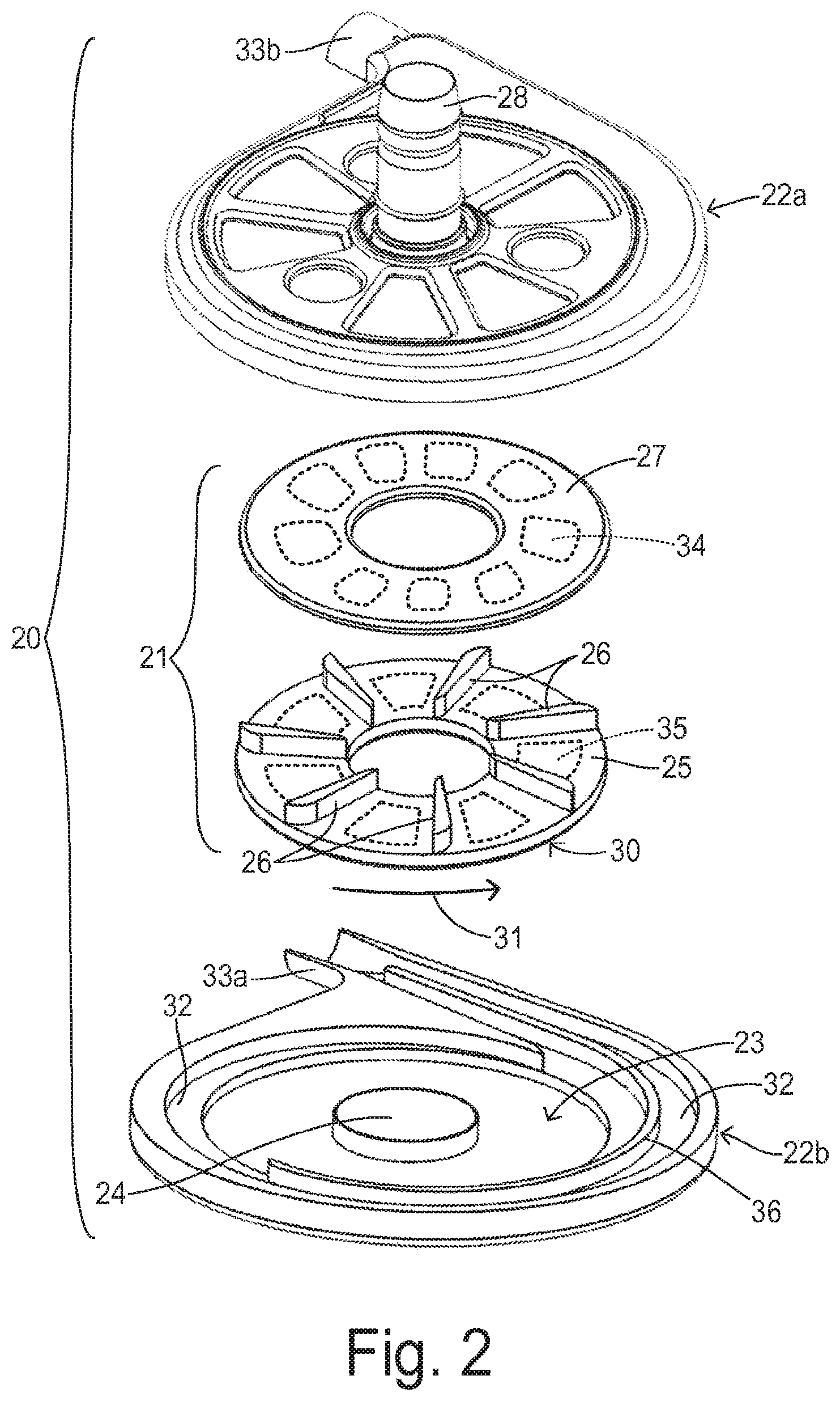
FIG. 2 is an exploded, perspective view of a portion of a centrifugal pump of a type that can be used in the present invention.
FIG. 3 is a diagram showing a prior art variable speed profile synchronized with a cardiac cycle.
FIG. 4 is a diagram showing a variable speed profile of the present invention.
FIG. 5 is a diagram showing a variable speed profile in greater detail.
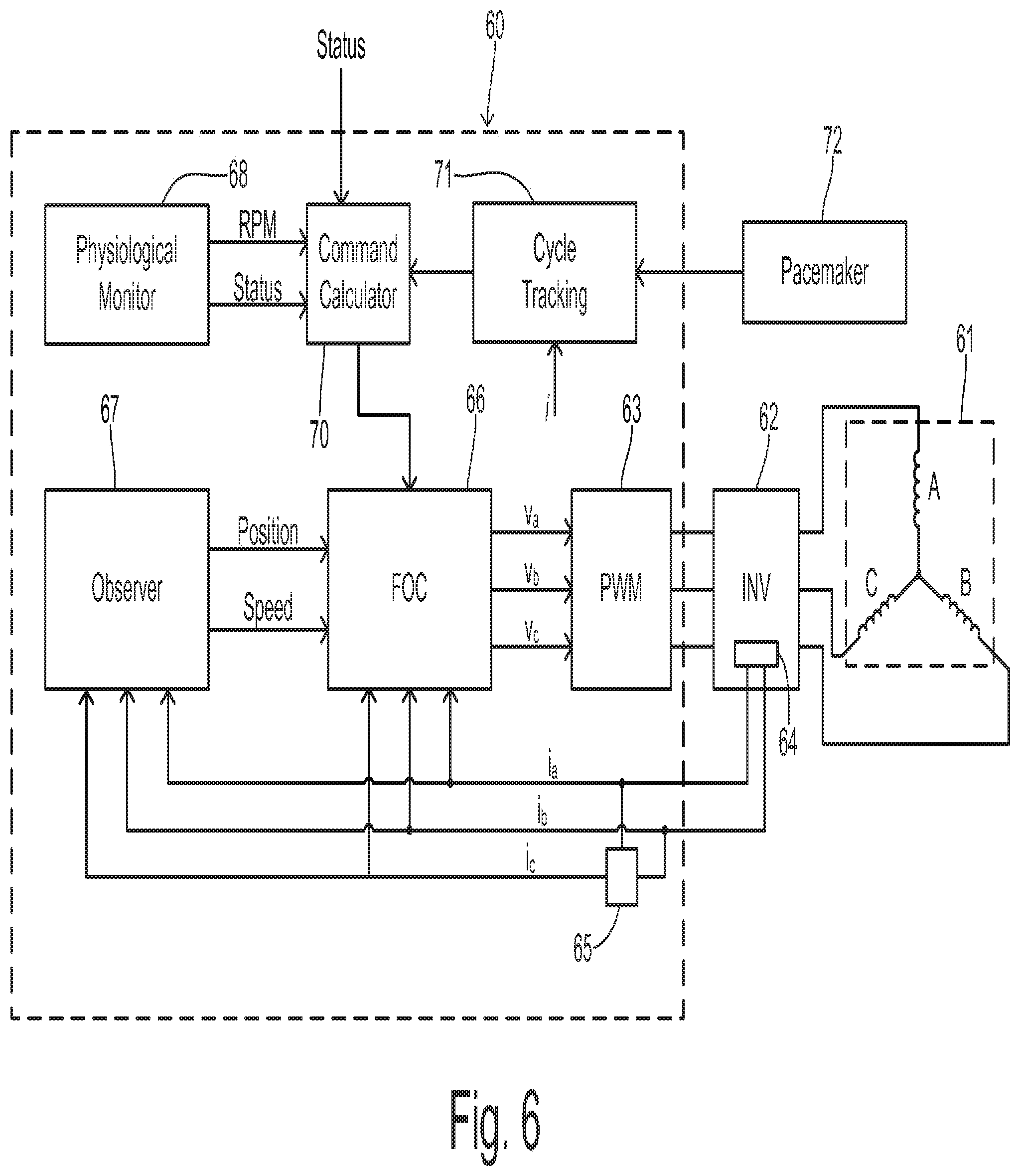
FIG. 6 is a block diagram showing a pump motor and control system of the present invention.
FIG. 7 is a diagram showing pump load and speed according to an embodiment using a constant current mode.
DETAILED DESCRIPTION OF PREFERRED EMBODIMENTS
Referring to FIG. 1, a patient 10 is shown in fragmentary front elevational view. Surgically implanted either into the patient's abdominal cavity or pericardium 11 is the pumping unit 12 of a ventricular assist device. An inflow conduit (on the hidden side of unit 12) pierces the heart to convey blood from the patient's left ventricle into pumping unit 12. An outflow conduit 13 conveys blood from pumping unit 12 to the patient's aorta. A percutaneous power cable 14 extends from pumping unit 12 outwardly of the patient's body via an incision to a compact control unit 15 worn by patient 10. Control unit 15 is powered by a main battery pack 16 and/or an external AC power supply and an internal backup battery. Control unit 15 includes a commutator circuit for driving a motor within pumping unit 12.
FIG. 2 shows a centrifugal pump unit 20 having an impeller 21 and a pump housing having upper and lower halves 22a and 22b. Impeller 21 is disposed within a pumping chamber 23 over a hub 24. Impeller 21 includes a first plate or disc 25 and a second plate or disc 27 sandwiched over a plurality of vanes 26. Second disc 27 includes a plurality of embedded magnet segments 34 for interacting with a levitating magnetic field created by a levitation magnet structure (not shown) that would be disposed against or incorporated in housing 22a. First disc 25 also contains embedded magnet segments 35 for magnetically coupling with a magnetic field from a motor (not shown) disposed against or incorporated in housing 22b. Housing 22a includes an inlet 28 for receiving blood from a patient's ventricle and distributing it to vanes 26. Impeller 21 is preferably circular and has an outer circumferential edge 30. By rotatably driving impeller 21 in a pumping direction 31, the blood received at an inner edge of impeller 21 is carried to outer circumferential 30 and enters a volute region 32 within pumping chamber 23 at an increased pressure. The pressurized blood flows out from an outlet 33 formed by housing features 33a and 33b. A flow-dividing guide wall 36 may be provided within volute region 32 to help stabilize the overall flow and the forces acting on impeller 21.
FIG. 3 shows a ventricular pressure curve 40 and a ventricular volume curve 41 according to a typical cardiac cycle. A pressure pulse 42 and a volume ejection 43 correspond with a systolic phase 44. A low ventricular pressure 45 and increasing ventricular volume 46 correspond with a diastolic phase 47. The start of systole corresponds with the time that the mitral or tricuspid valve closes, and the start of diastole corresponds with the time that the aortic valve or pulmonary valve closes. Curve 48 shows a pulsatile pump flow in which the pump speed is synchronously varied in order to provide an increased speed during systolic phase 44 and a decreased speed during diastolic phase 47. As explained above, this conventional pulsatile flow does not significantly unload the ventricle at the beginning of systole.
FIGS. 4 and 5 show a first embodiment of the invention for providing a variable speed mode with certain speed changes preceding the beginning of systole 50 and the beginning of diastole 51. An impeller speed curve 52 provides a pulsatile flow between an elevated speed 53 and a reduced speed 54. Curve 49 shows a representative current vector applied to the motor by the motor controller in order to generate a corresponding target speed. Thus, an increase in current generates a speed increase and a decrease in current generates a speed decrease. The target speed includes a ramping up at segment 55 from reduced speed 54 to elevated speed 53, wherein the ramping up begins during diastole. The time of increase and the slope of the increase are configured to provide an increasing flow before systole begins to provide a reduced ventricular pressure that allows a weak ventricle to contract with reduced resistance. The controlled motor current 49 begins to increase at a time 56 which precedes systole by a time period t.sub.1. The beginning of ramping up segment 55 of the speed may lag the current increase but still occurs prior to the beginning of systole 50. Preferably, time 56 is scheduled by the motor controller at time t.sub.1 before the next expected occurrence of systole 50 such that the ramping up begins at a moment between about 50% to about 90% into the diastolic phase. Thus, denoting the length of the diastolic phase as t.sub.D, the ratio t.sub.1/t.sub.D is preferably between 0.1 and 0.5.
To help avoid collapse of the ventricle toward the end of systole or during diastole, impeller speed 52 preferably ramps down at segment 57 from elevated speed 53 to reduced speed 54. Segment 57 begins during the systolic phase of the cardiac cycle (i.e., before the beginning of diastole 51). For example, current curve 49 starts to ramp down at a time 58 which precedes start of diastole 51 by a time t.sub.2. Preferably, time 58 may be at a moment between about 50% to about 90% into the systolic phase. Thus, denoting the length of the systolic phase as t.sub.s, the ratio t.sub.1/t.sub.s is preferably between 0.1 and 0.5.
As shown in FIG. 5, an average speed 59 is maintained as the instantaneous speed varies between elevated speed 53 and reduced speed 54. Average speed 59 may be determined in a conventional manner according to the physiological state of the patient. Offsets from average speed 59 for elevated speed 53 and reduced speed 54 may be substantially constant or may also be determined according to the physiological state of the patient.
A pump system of the present invention is shown in greater detail in FIG. 6 wherein a controller 60 uses field oriented control (FOC) to supply a multiphase voltage signal to the pump motor which comprises a stator assembly 61 shown as a three-phase stator. Individual phases A, B, and C are driven by an H-bridge inverter 62 functioning as a commutation circuit driven by a pulse width modulator (PWM) circuit 63 in controller 60. A current sensing circuit 64 associated with inverter 62 measures instantaneous phase current in at least two phases providing current signals designated i.sub.a and i.sub.b. A current calculating block 65 receives the two measured currents and calculates a current i.sub.c corresponding to the third phase as known in the art. The measured currents are input to an FOC block 66 and to a current observer block 67 which estimates the position and speed of the impeller as known in the art. The impeller position and speed are input to FOC block 66.
An average target speed or rpm for operating the pump is provided by a physiological monitor 68 to FOC block 66. The average rpm may be set by a medical caregiver or may be determined according to an algorithm based on various patient parameters such heart beat. Monitor 68 may also generate a status signal for identifying whether the ventricle is in the initial, highly weakened state or whether a predetermined recovery has been obtained in the strength of the ventricle. The average rpm and the status signal are provided to a speed command calculator 70. The status signal can be used to determine whether or not the variable speed control of the invention should be used to unload the ventricle. The status signal can alternatively be externally provided to calculator 70 (e.g., by a physician via an HMI).
Command calculator 70 is coupled to a cycle tracking block 71 which maintains timing for a cardiac cycle reference. A current signal (e.g., currents i.sub.a, i.sub.b, and i.sub.c) can be used in order to detect the cardiac cycle from the instantaneous blood flow, for example. More specifically, the controller may identify the heart rate by measuring time between current peaks in the speed control mode. Then the speed decrease can start at a calculated time after the occurrence of a current peak. The speed increase can start at a calculated time after the current minimum value is to detected. This calculated time typically depends on the heart rate.
Alternatively, cycle tracking block 71 can be coupled to a pacemaker 72 in the event that the patient is using such a device. Conventional pacemakers have been constructed to continuously generate radio signals that contain information about pulse timing and other data. These sine-wave modulated signals can be received by a special receiver (not shown), where the signals are demodulated, digitized (if necessary), and transferred to cycle tracking block 71. Besides being located near the implanted pacemaker and connected by a cable or wirelessly to the controller (e.g., via BlueTooth), a receiver could be integrated with the controller or the pumping unit.
Based on the reference cycle timing from block 71, command calculator 70 determines an instantaneous speed (or magnitude of the current vector) to be used by FOC block 66. FOC block 66 generates commanded voltage output values v.sub.a, v.sub.b, and v.sub.c which are input to PWM block 63. The v.sub.a, v.sub.b, and v.sub.c commands may also be coupled to observer 67 for use in detecting speed and position (not shown). Thus, the speed is controlled to follow the curves shown in FIGS. 4 and 5.
In one embodiment, the timing of the speed increases and decreases are determined as follows. At a constant pacing rate (i.e., constant beat rate), the time for starting the speed acceleration (e.g., at time 56 in FIG. 4) is: t.sub.acc(n+1)=t.sub.p(n).sub.+60/N-t.sub.1. where t.sub.p(n) is the time of occurrence of a pacemaker pulse time signaling the start of the current cardiac cycle; N is the heart (pulse) rate in beat/min set by a pacemaker; and t.sub.acc(n+1) is the time to increase the pump speed for the next cardiac cycle. Similarly, the time to start deceleration (e.g., at a time 58 in FIG. 4) is: t.sub.decel(n+1)=t.sub.a(n+1)+t.sub.s where t.sub.s is the duration of systole. Systole typically lasts 30% to 50% of the cardiac cycle 60/N, and within a certain heart rate range it is fairly independent of the heart rate N. For example, for a heart rate N between 60-120 beats/min, t.sub.s is between 0.30 seconds and 0.25 seconds.
In an alternative embodiment, command calculator 70 and FOC block 66 are configured to operate the motor in a constant current mode (i.e., a constant torque mode). In this mode, the speed changes inversely with the pump load (i.e., the flow rate). Thus, an average speed is determined by the physiological monitor. The motor controller adjusts the current to obtain the desired average speed and to keep the current substantially constant. By keeping a constant current in the face of a load which varies within the cardiac cycle, the impeller speed automatically changes. FIG. 7 shows a load curve 75, wherein the load (i.e., flow rate) is high at 76 during systole and low at 77 during diastole. The load ramps up at 78 before the beginning of systole due to an increase of pressure within the ventricle and a decrease of pressure at the pump outlet (e.g., at the aorta). The load ramps down at 80 during the beginning of diastole.
In the current control mode, the pump flow increases (load increases) in the beginning of systole (at 78) and the speed curve 81 drops to a reduced speed 83. At the end of systole, the flow drops (at 80) and speed increases to an elevated speed 82. Thus, the speed increases and stays relatively high during diastole to help unload the ventricle by pumping out blood at the time it fills the ventricle. This is a natural behavior of the pump in the current control mode.
Either the variable speed control mode using a variable target speed or using the constant current approach of the invention can be combined with the conventional constant speed mode in order to adapt pump performance to the strength level of the patient's ventricle. In particular, the selection between the variable speed mode and the constant speed mode can be determined according to a physiologic capability of the patient. For example, the pump is set to operate in the constant current mode immediately following the implantation when the left ventricle is weak, thereby providing a greater level of ventricle unloading. With the patient's recovery, the pump may be set to operate in the constant speed mode, promoting higher flow pulsatility and a more natural physiologic response to the patient's activities.
* * * * *
D00000
D00001
D00002
D00003
D00004
XML
uspto.report is an independent third-party trademark research tool that is not affiliated, endorsed, or sponsored by the United States Patent and Trademark Office (USPTO) or any other governmental organization. The information provided by uspto.report is based on publicly available data at the time of writing and is intended for informational purposes only.
While we strive to provide accurate and up-to-date information, we do not guarantee the accuracy, completeness, reliability, or suitability of the information displayed on this site. The use of this site is at your own risk. Any reliance you place on such information is therefore strictly at your own risk.
All official trademark data, including owner information, should be verified by visiting the official USPTO website at www.uspto.gov. This site is not intended to replace professional legal advice and should not be used as a substitute for consulting with a legal professional who is knowledgeable about trademark law.