Apparatus and methods for paper dispensing
Falk , et al. April 20, 2
U.S. patent number 10,980,377 [Application Number 16/719,087] was granted by the patent office on 2021-04-20 for apparatus and methods for paper dispensing. This patent grant is currently assigned to Essity Hygiene and Health Aktiebolag. The grantee listed for this patent is Essity Hygiene and Health Aktiebolag. Invention is credited to John P. Devlin, Magnus Falk, Peter McNulty, Jeffrey Mekler, Nathan Rollins.


View All Diagrams
| United States Patent | 10,980,377 |
| Falk , et al. | April 20, 2021 |
Apparatus and methods for paper dispensing
Abstract
A method for loading a stack of interfolded paper units into a dispenser includes inserting a stack of interfolded paper units into an interior volume of the dispenser through a dispenser opening. The dispenser has a lid having a dispensing aperture, as well as a movable platen that has a paper-engaging surface, and which is urged upwardly toward the dispenser opening. A bottom wall of the dispenser is disposed opposite the dispenser opening, and a lock of the dispenser is selectively engageable with the platen. The stack is placed on the platen and a downward force is exerted on the top surface of the stack to thereby push the platen downward until the platen has been engaged by the lock and has reached a locked position in which the paper-engaging surface has an oblique orientation relative to the bottom wall of the dispenser.
| Inventors: | Falk; Magnus (Gothenburg, SE), Devlin; John P. (Tewksbury, MA), McNulty; Peter (Seattle, WA), Mekler; Jeffrey (San Francisco, CA), Rollins; Nathan (Boylston, MA) | ||||||||||
|---|---|---|---|---|---|---|---|---|---|---|---|
| Applicant: |
|
||||||||||
| Assignee: | Essity Hygiene and Health
Aktiebolag (Gothenburg, SE) |
||||||||||
| Family ID: | 1000004611684 | ||||||||||
| Appl. No.: | 16/719,087 | ||||||||||
| Filed: | December 18, 2019 |
| Current U.S. Class: | 1/1 |
| Current CPC Class: | A47K 10/422 (20130101); A47K 2010/3233 (20130101) |
| Current International Class: | A47K 10/42 (20060101); A47K 10/32 (20060101) |
| Field of Search: | ;221/45,59,46 |
References Cited [Referenced By]
U.S. Patent Documents
| 340355 | April 1886 | Ramser |
| 744047 | November 1903 | Casterline et al. |
| 777082 | December 1904 | Cutler |
| 1111962 | September 1914 | Hooper |
| 1114354 | October 1914 | Hildebrand |
| 1151064 | August 1915 | Swift |
| 1163737 | December 1915 | Calvert |
| 1257413 | February 1918 | Hill |
| 1333045 | March 1920 | Swift |
| 1362449 | December 1920 | Teall |
| 1503241 | July 1924 | Horwitt |
| 1508020 | September 1924 | Horwitt |
| 1513792 | November 1924 | Arelt |
| 1563078 | November 1925 | Erdos |
| 1703594 | February 1929 | Pratt |
| 1752885 | April 1930 | Carroll |
| 1784836 | December 1930 | Hess |
| 1893725 | January 1933 | Boomershine |
| 1898983 | February 1933 | Wheeler, Jr. |
| 1901243 | March 1933 | Horwitt |
| 1993885 | March 1935 | Horwitt |
| 2081564 | May 1937 | Tuszynski |
| 2092166 | September 1937 | Kettles, Jr. |
| 2253742 | August 1941 | West |
| 2337065 | December 1943 | Price |
| 2354058 | July 1944 | Ridgeway |
| 2426136 | August 1947 | Agamaite, Jr. |
| 2491615 | December 1949 | Laid |
| 2689059 | September 1954 | Nudell |
| 2765909 | October 1956 | Graham |
| 2772021 | November 1956 | Kettles |
| 2849153 | August 1958 | Tuttle |
| 2876884 | March 1959 | Hastie |
| 2932426 | April 1960 | Hope et al. |
| 3028047 | April 1962 | Tuft |
| 3117694 | January 1964 | Gothreau |
| 3119516 | January 1964 | Donovan |
| 3121510 | February 1964 | Holzwarth |
| 3208634 | September 1965 | Saxe |
| 3214227 | October 1965 | Edwin |
| 3291339 | December 1966 | Hein |
| 3425595 | February 1969 | Shapira |
| 3425685 | February 1969 | Liva |
| 3606125 | September 1971 | Tucker et al. |
| 3608891 | September 1971 | Hannon et al. |
| 3652174 | March 1972 | Boone |
| 3674175 | July 1972 | Jaquish |
| 3777929 | December 1973 | Hannon et al. |
| 3777931 | December 1973 | Fleming |
| 3785523 | January 1974 | Goldstein |
| 3979020 | September 1976 | Braber et al. |
| 4094442 | June 1978 | Radek |
| 4118085 | October 1978 | Fibus |
| 4143792 | March 1979 | Rex |
| 4234101 | November 1980 | Pastore |
| 4249460 | February 1981 | McSwain |
| 4280692 | July 1981 | Hutchinson |
| 4311252 | January 1982 | Hope, Jr. |
| 4329001 | May 1982 | Filipowicz |
| 4372549 | February 1983 | Stiernspetz |
| 4413749 | November 1983 | Glaser |
| 4416392 | November 1983 | Smith |
| 4494948 | January 1985 | Teyssier, Jr. |
| 4526291 | July 1985 | Margulies |
| D282574 | February 1986 | Case et al. |
| 4638921 | January 1987 | Sigl et al. |
| 4662536 | May 1987 | Powers |
| 4838454 | June 1989 | Salzmann |
| 4919377 | April 1990 | Alexander et al. |
| 4938382 | July 1990 | Frazier |
| 4953747 | September 1990 | Wenkman |
| D310923 | October 1990 | Breger |
| 4969575 | November 1990 | Kobayashi |
| 5011010 | April 1991 | Francis et al. |
| 5076466 | December 1991 | Petterson et al. |
| 5082229 | January 1992 | Dahl |
| 5090592 | February 1992 | Petterson |
| 5100020 | March 1992 | Petterson |
| 5102007 | April 1992 | Petterson et al. |
| 5123566 | June 1992 | Lage et al. |
| 5131561 | July 1992 | Casperson et al. |
| 5190186 | March 1993 | Yablans et al. |
| 5199599 | April 1993 | Shade |
| 5222628 | June 1993 | Roethel |
| 5261557 | November 1993 | Bytell et al. |
| 5269409 | December 1993 | Brandt et al. |
| 5356032 | October 1994 | Rhodes |
| 5513773 | May 1996 | Cargill |
| 5515999 | May 1996 | Jo |
| 5535320 | July 1996 | Gay et al. |
| 5586685 | December 1996 | Dorner et al. |
| 5616113 | April 1997 | Van Den Bergh |
| 5630581 | May 1997 | Rodesch |
| 5632409 | May 1997 | Raghunanan |
| 5638962 | June 1997 | Price, Jr. |
| 5678728 | October 1997 | Leto |
| 5690230 | November 1997 | Griffith |
| 5743605 | April 1998 | Marino |
| 5813569 | September 1998 | Cihanek |
| 5823344 | October 1998 | Fantone et al. |
| 5823353 | October 1998 | Perrin et al. |
| 5857791 | January 1999 | Kenney |
| 5865340 | February 1999 | Alvern |
| 5894931 | April 1999 | Dunn |
| 5908137 | June 1999 | Pattarozzi |
| 6003723 | December 1999 | Morand |
| 6056133 | May 2000 | Luenser |
| 6145231 | November 2000 | Valiulis |
| 6230929 | May 2001 | Phelps et al. |
| 6257443 | July 2001 | LaCount |
| 6286713 | September 2001 | Chan |
| 6331696 | December 2001 | Nakamura |
| 6334544 | January 2002 | Christensen et al. |
| 6354462 | March 2002 | Conran et al. |
| 6378726 | April 2002 | Chan et al. |
| 6386389 | May 2002 | Percy et al. |
| 6427838 | August 2002 | Fulda |
| 6440052 | August 2002 | Reider et al. |
| D463184 | September 2002 | Tramontina et al. |
| 6457605 | October 2002 | Coleman |
| 6519885 | February 2003 | Valiulis |
| 6542641 | April 2003 | Andrew et al. |
| 6543643 | April 2003 | Iida et al. |
| 6592118 | July 2003 | Youn |
| 6655544 | December 2003 | Tanaka et al. |
| 6704616 | March 2004 | Formon |
| 6705473 | March 2004 | Schlesinger |
| 6726014 | April 2004 | Laurent |
| 6772908 | August 2004 | Roethel et al. |
| 6783411 | August 2004 | Pither |
| 6789694 | September 2004 | McCullough |
| 6824007 | November 2004 | Timmers |
| 6830151 | December 2004 | Spencer et al. |
| 6871755 | March 2005 | DeVries et al. |
| 6874653 | April 2005 | Boone et al. |
| 6892898 | May 2005 | Boone et al. |
| 6929147 | August 2005 | Guillemette et al. |
| 6964349 | November 2005 | Sears et al. |
| 6981610 | January 2006 | Smiley |
| 6988635 | January 2006 | Hochtritt et al. |
| 7048143 | May 2006 | Sanders et al. |
| D524084 | July 2006 | Wieser et al. |
| 7093737 | August 2006 | Tramontina et al. |
| 7124911 | October 2006 | Tramontina et al. |
| 7134571 | November 2006 | Hochtritt |
| 7178689 | February 2007 | Wieser |
| 7219852 | May 2007 | Tramontina et al. |
| 7234610 | June 2007 | Skarda et al. |
| 7370860 | May 2008 | James, III et al. |
| 7543423 | June 2009 | Long et al. |
| 7661553 | February 2010 | Zeiron |
| 7721913 | May 2010 | Nash |
| 7837057 | November 2010 | Zeiron |
| 7922035 | April 2011 | Long et al. |
| 7938294 | May 2011 | Cittadino |
| 8328046 | December 2012 | Hochtritt et al. |
| D675851 | February 2013 | Wilson |
| D692730 | November 2013 | Wilson, Jr. et al. |
| 8590738 | November 2013 | Formon et al. |
| D701434 | March 2014 | Wilson, Jr. |
| D705015 | May 2014 | Wilson, Jr. et al. |
| D705016 | May 2014 | Wilson, Jr. et al. |
| D705017 | May 2014 | Siebel |
| 8757432 | June 2014 | Muntzing |
| 8863984 | October 2014 | Siebel |
| 8881943 | November 2014 | Kobayashi |
| D729541 | May 2015 | Wilson, Jr. |
| D740049 | October 2015 | Wilson, Jr. |
| D745336 | December 2015 | Rittfeldt et al. |
| D745337 | December 2015 | Rittfeldt et al. |
| 9345368 | May 2016 | Formon et al. |
| 9433331 | September 2016 | Siebel |
| 9622627 | April 2017 | Wilson |
| 9901221 | February 2018 | Larsson |
| 9901222 | February 2018 | Wilson et al. |
| 9986876 | June 2018 | Brickl et al. |
| 10004366 | June 2018 | Chalko |
| 10083566 | September 2018 | McPake |
| 10405705 | September 2019 | Formon et al. |
| 10602890 | March 2020 | Billman |
| 2001/0020624 | September 2001 | Hubanks et al. |
| 2002/0030061 | March 2002 | Formon |
| 2002/0070228 | June 2002 | Moody |
| 2002/0139813 | October 2002 | Boone et al. |
| 2002/0179624 | December 2002 | Tramontina |
| 2003/0019880 | January 2003 | Timmers et al. |
| 2003/0057221 | March 2003 | Guillemette et al. |
| 2003/0062375 | April 2003 | Christensen et al. |
| 2003/0071050 | April 2003 | Clark |
| 2003/0080137 | May 2003 | Clark et al. |
| 2003/0116580 | June 2003 | Baughman |
| 2003/0146240 | August 2003 | Kawolics |
| 2004/0007586 | January 2004 | Boone et al. |
| 2004/0050857 | March 2004 | Norton |
| 2004/0178648 | September 2004 | Moses |
| 2004/0178948 | September 2004 | Axelsson |
| 2004/0222582 | November 2004 | Widlund |
| 2005/0056656 | March 2005 | Hochtritt et al. |
| 2005/0150898 | July 2005 | Young et al. |
| 2005/0199643 | September 2005 | Smiley et al. |
| 2006/0027590 | February 2006 | Tramontina |
| 2006/0076357 | April 2006 | Braat et al. |
| 2006/0086748 | April 2006 | Burns |
| 2006/0102641 | May 2006 | Cittadino |
| 2006/0102642 | May 2006 | Muntzing et al. |
| 2006/0169712 | August 2006 | Yitzchaki |
| 2006/0273100 | December 2006 | Cittadino et al. |
| 2006/0273101 | December 2006 | Lewis et al. |
| 2006/0273102 | December 2006 | Wieser et al. |
| 2007/0034638 | February 2007 | Zeiron |
| 2007/0152010 | July 2007 | Denen et al. |
| 2007/0215634 | September 2007 | Levin |
| 2008/0113855 | May 2008 | Gooding, Jr. |
| 2008/0135570 | June 2008 | Lee |
| 2008/0142536 | June 2008 | Cohen et al. |
| 2009/0212150 | August 2009 | Wruck, Jr. et al. |
| 2009/0272755 | November 2009 | Burns |
| 2009/0277920 | November 2009 | Cittadino et al. |
| 2010/0114366 | May 2010 | Case et al. |
| 2010/0224647 | September 2010 | Formon et al. |
| 2010/0274384 | October 2010 | Nordlund et al. |
| 2011/0095042 | April 2011 | Bandoh |
| 2011/0132920 | June 2011 | Petocchi |
| 2011/0174834 | July 2011 | Case |
| 2013/0161346 | June 2013 | Wolme et al. |
| 2014/0014675 | January 2014 | Ingvarsson et al. |
| 2014/0116913 | May 2014 | Thorburn et al. |
| 2014/0319164 | October 2014 | Wilson |
| 2015/0031257 | January 2015 | Ootsubo |
| 2016/0029857 | February 2016 | Woerpel et al. |
| 2016/0051100 | February 2016 | Formon et al. |
| 2016/0088982 | March 2016 | Larsson |
| 2016/0090229 | March 2016 | Stenberg |
| 1168089 | Dec 1997 | CN | |||
| 1257413 | Jun 2000 | CN | |||
| 1327427 | Dec 2001 | CN | |||
| 2528370 | Jan 2003 | CN | |||
| 2546386 | Apr 2003 | CN | |||
| 1593318 | Mar 2005 | CN | |||
| 1678228 | Oct 2005 | CN | |||
| 1767779 | May 2006 | CN | |||
| 101014272 | Aug 2007 | CN | |||
| 101186075 | May 2008 | CN | |||
| 101331063 | Dec 2008 | CN | |||
| 101983027 | Mar 2011 | CN | |||
| 102368941 | Mar 2012 | CN | |||
| 202376008 | Aug 2012 | CN | |||
| 19514431 | Nov 1995 | DE | |||
| 1238619 | Sep 2002 | EP | |||
| 1656870 | May 2006 | EP | |||
| 1693304 | Aug 2006 | EP | |||
| 2335541 | Jun 2011 | EP | |||
| 2850985 | Mar 2015 | EP | |||
| 1285715 | Feb 1962 | FR | |||
| 2538695 | Jul 1984 | FR | |||
| 2551964 | Mar 1985 | FR | |||
| 2732579 | Oct 1996 | FR | |||
| 2357080 | Jun 2001 | GB | |||
| 0301297 | May 1968 | SE | |||
| 0189354 | Nov 2001 | WO | |||
| 2004093629 | Nov 2004 | WO | |||
| 2005107546 | Nov 2005 | WO | |||
| 2005107548 | Nov 2005 | WO | |||
| 2006132618 | Dec 2006 | WO | |||
| 2006132696 | Dec 2006 | WO | |||
| WO-2006132618 | Dec 2006 | WO | |||
| 2013055340 | Apr 2013 | WO | |||
| 2018054455 | Mar 2018 | WO | |||
Other References
|
Janet Beighle-French, New Products Ease Home Frustrations, Nov. 11, 1996, The Plain Dealer, Cleveland, Ohio, p. 7.D. cited by applicant . Joel Palmer, Rolling Meadows parks pursues deal with Pepsi bottler, Sep. 24, 1997, Chicago Daily Herald, News; p. 4. cited by applicant . Plasticrafters Website, Displays2Go.com, Jan. 11, 2002, p. 1-2. cited by applicant. |
Primary Examiner: Kumar; Rakesh
Attorney, Agent or Firm: Wood Herron & Evans LLP
Claims
What is claimed is:
1. A method for loading a stack of interfolded paper units into a dispenser, the method comprising: inserting the stack of interfolded paper units into an interior volume of the dispenser through a dispenser opening, wherein the stack includes a bottom surface and an oppositely disposed top surface, the bottom surface defining a footprint area of the stack, and wherein the dispenser includes a plurality of sidewalls and a lid connected to a pair of the plurality of sidewalls for selectively covering the dispenser opening, the lid having a dispensing aperture, the dispenser further including a movable platen having a paper-engaging surface and being urged upwardly toward the dispenser opening, a bottom wall disposed opposite the dispenser opening, and a rotatable spring-loaded lock selectively engageable with the platen and rotatably movable with respect to the platen, the spring-loaded lock being coupled to one of the plurality of sidewalls at a pivoting location so as to be rotatable about the pivoting location; placing the stack on the paper-engaging surface of the platen in the interior volume of the dispenser; exerting a downward force on the top surface of the stack to thereby push the platen downward, downward movement of the platen causing the rotatable spring-loaded lock to rotate about a lock axis in a first direction, the rotatable spring-loaded lock being biased to rotate in a second direction opposite the first direction; ceasing exertion of the downward force when the platen has been engaged by the rotatable spring-loaded lock and has reached a locked position in which the paper-engaging surface has an oblique orientation relative to the bottom wall of the dispenser; pivoting the lid about a lid axis from an open position toward a closed position of the lid to thereby cause rotation of the rotatable spring-loaded lock in the first direction, rotation of the spring-loaded lock in the first direction causing the rotatable spring-loaded lock to disengage from the platen; and extending a portion of an individual paper unit from the top surface of the stack through the dispensing aperture of the lid, to thereby dispense that individual paper unit.
2. The method of claim 1, wherein a ratio of the footprint area of the stack to the paper-engaging surface of the platen is in the range of about 0.7 to about 1.
3. The method of claim 2, wherein the ratio of the footprint area of the stack to the paper-engaging surface of the platen is in the range of about 0.85 to about 1.
4. The method of claim 3, wherein the ratio of the footprint area of the stack to the paper-engaging surface of the platen is in the range of about 0.95 to about 1.
5. The method of claim 1, wherein the paper-engaging surface of the platen has a first platen edge adjacent the lid axis, and a second platen edge opposite the first platen edge, the oblique orientation of the paper-engaging surface of the platen in the locked position of the platen being such that the first platen edge is closer than the second platen edge to the bottom wall of the dispenser.
6. The method of claim 1, wherein the top surface of the stack includes a first pair of surface edges parallel to one another, and a second pair of surface edges orthogonal to the first pair of surface edges, the first and second pairs of surface edges jointly defining a perimeter of the top surface of the stack, the top surface of the stack further including a linear gripping tab generally parallel to the first pair of surface edges and extending between the second pair of surface edges.
7. The method of claim 1, further comprising: pushing the lid relative to a remainder of the dispenser, when the lid is in the closed position of the lid, in a direction toward the lid axis to thereby permit pivoting movement of the lid relative to the remainder of the dispenser.
8. The method of claim 1, wherein placing the stack on the paper-engaging surface of the platen in the interior volume of the dispenser includes placing a stack on the paper-engaging surface that has a height no greater than about 110 mm and a number of interfolded paper units no greater than about 120.
9. A method for loading a stack of interfolded paper units into a dispenser, the method comprising: inserting the stack of interfolded paper units into an interior volume of the dispenser through a dispenser opening, wherein the stack includes a bottom surface and an oppositely disposed top surface, the bottom surface defining a footprint area of the stack, the top surface of the stack including a first pair of surface edges parallel to one another, and a second pair of surface edges orthogonal to the first pair of surface edges, the first and second pairs of surface edges jointly defining a perimeter of the top surface of the stack, the top surface of the stack further including a linear gripping tab generally parallel to the first pair of surface edges and extending between the second pair of surface edges, and wherein the dispenser includes a lid connected to a remainder of the dispenser for selectively covering the dispenser opening, the lid having a dispensing aperture including an elongated shape having a length dimension and a width dimension, the dispenser further including a movable platen having a paper-engaging surface and being urged upwardly toward the dispenser opening, a bottom wall disposed opposite the dispenser opening, and a lock selectively engageable with the platen; placing the stack on the paper-engaging surface of the platen in the interior volume of the dispenser and orienting the stack such that the gripping tab is orthogonal to the length dimension of the dispensing aperture; exerting a downward force on the top surface of the stack to thereby push the platen downward, downward movement of the platen being effective to pivot the lock about a lock axis in a first direction, the lock being biased to move in a second direction opposite the first direction; ceasing exertion of the downward force when the platen has been engaged by the lock and has reached a locked position in which the paper-engaging surface has an oblique orientation relative to the bottom wall of the dispenser; pivoting the lid about a lid axis from an open position toward a closed position of the lid to thereby cause pivoting of the lock in the first direction, pivoting of the lock in the first direction being effective to cause the lock to disengage from the platen; and extending a portion of an individual paper unit from the top surface of the stack through the dispensing aperture of the lid, to thereby dispense that individual paper unit.
10. The method of claim 9, wherein the dispensing aperture has a centrally located section and a pair of slotted sections on each side of the centrally located section, the width of the dispensing aperture in the centrally located section being greater than the width of the dispensing aperture in each of the slotted sections, the method including placing the stack on the paper-engaging surface of the platen such that the gripping tab is located within the centrally located section.
11. The method of claim 10, wherein each of the slotted sections has a width no greater than about 13 mm.
12. The method of claim 10, wherein the centrally located section has a width of less than about 30 mm.
13. The method of claim 10, wherein the centrally located section has a length no greater than about 40 mm.
Description
CROSS-REFERENCE TO RELATED APPLICATIONS
This application is related to co-owned application titled HORIZONTALLY ORIENTED PAPER PRODUCT DISPENSER AND RELATED METHODS, Ser. No. 16/718,950, filed on even date herewith, and the disclosure of which is hereby incorporated by reference in its entirety.
TECHNICAL FIELD
The present disclosure is generally related to dispensers and, more particularly, to dispensers of paper product and methods for dispensing such paper product.
SUMMARY
In one embodiment, a method is disclosed for loading a stack of interfolded paper units into a dispenser. The stack has a bottom surface, as well as an oppositely disposed top surface, with the bottom surface defining a footprint area of the stack. The method includes inserting the stack of interfolded paper units into an interior volume of the dispenser through a dispenser opening, with the dispenser including a lid that is connected to a remainder of the dispenser for selectively covering the dispenser opening. The lid has a dispensing aperture, as well as a movable platen that has a paper-engaging surface, and which is urged upwardly toward the dispenser opening. A bottom wall of the dispenser is disposed opposite the dispenser opening, and a lock of the dispenser is selectively engageable with the platen.
The method includes placing the stack on the paper-engaging surface of the platen in the interior volume of the dispenser, and exerting a downward force on the top surface of the stack to thereby push the platen downward. Downward movement of the platen is effective to pivot the lock about a lock axis in a first direction, with the lock being biased to move in a second direction opposite the first direction. Exertion of the downward force is ceased when the platen has been engaged by the lock and has reached a locked position in which the paper-engaging surface has an oblique orientation relative to the bottom wall of the dispenser. The method further includes pivoting the lid about a lid axis from an open position toward a closed position of the lid, to thereby cause pivoting movement of the lock in the first direction. Pivoting movement of the lock in the first direction is effective to cause the lock to disengage from the platen. The method also includes extending a portion of an individual paper unit from the top surface of the stack through the dispensing aperture of the lid, to thereby dispense that individual paper unit.
In another embodiment a napkin dispenser is provided. The napkin dispenser includes a bottom wall and a plurality of sidewalls that jointly define an interior volume of the dispenser for storing napkins therein. A lid is connected to one or more of the sidewalls for selectively allowing access into the interior volume. The lid includes a dispensing aperture that is configured to allow extraction of the napkins one at a time from the interior volume. The dispensing aperture has an elongated shape and includes a length dimension, as well as a width dimension. The dispensing aperture has a centrally located section, and a pair of slotted sections each extending from the centrally located section. The centrally located section has a length that is no greater than about 40 mm, and each of the slotted sections has a width that is no greater than about 13 mm.
In yet another embodiment, a napkin dispenser is provided that includes a bottom wall and a plurality of sidewalls, with that bottom wall and the sidewalls jointly defining an interior volume of the dispenser for storing napkins therein. The dispenser includes a lid that is connected to one or more of the sidewalls for selectively allowing access into the interior volume, with the lid having a dispensing aperture that is configured to allow extraction of the napkins one at a time from the interior volume. The lid is pivotally movable relative to the sidewalls between an open position and a closed position. The dispenser also includes a platen that is movable between a bottom position proximate the bottom wall, and a top position. A first biasing element is coupled to the platen and urges the platen toward the top position of that platen. The dispenser also includes a lock associated with one or more of the sidewalls and which has a locked condition in which the lock prevents the platen for moving towards the top position of the platen, and also an unlocked condition in which the platen is permitted to move toward the top position of the platen. The platen is configured to move the lock into the locked condition as the platen moves toward the bottom position of the platen. Pivoting movement of the lid from the open position to the closed position of that lid is configured to move the lock toward the unlocked condition of the lock.
In another embodiment a system for dispensing napkins is provided, which includes a dispenser for storing and dispensing individual napkins from a stack of such napkins. The dispenser in that system has a bottom wall and a plurality of sidewalls jointly defining an interior volume of the dispenser for storing the napkins. A lid of the dispenser is hingedly coupled to one or more of the sidewalls for selectively allowing access into the interior volume, with the lid including a dispensing aperture that is configured to allow extraction of the napkins one at a time from the interior volume. The system further includes a stack of interfolded napkins in the interior volume of the dispenser, with that stack having a generally rectangular footprint. The rectangular footprint includes a length not exceeding about 115 mm, and a width not exceeding about 95 mm. The dispensing aperture has an elongated shape and includes a length dimension and a width dimension. The dispensing aperture has a centrally located section, and a pair of slotted sections each extending from the centrally located section. The centrally located section has a length that is no greater than about 40 mm, and each of the slotted sections has a width that is no greater than about 13 mm.
In specific embodiments, the stack has a height that is no greater than about 110 mm, and a number of interfolded napkins that is no greater than about 120. The stack may include a top surface, a first pair of surface edges parallel to one another, and a second pair of surface edges orthogonal to the first pair of surface edges, with the first and second pairs of surface edges jointly defining a perimeter of the top surface of the stack. The top surface in those embodiments may include a linear gripping tab that is generally parallel to the first pair of surface edges, and which extends between the second pair of surface edges. In those embodiments, the stack may be located in the interior volume of the dispenser such that the gripping tab is accessible only through the centrally located section of the dispensing aperture. In those or other specific embodiments, the stack may be oriented in the interior volume of the dispenser such that the linear gripping tab is orthogonal to the length dimension of the dispensing aperture.
BRIEF DESCRIPTION OF THE DRAWINGS
The objectives and features of the invention will become more readily apparent from the following detailed description taken in conjunction with the accompanying drawings in which:
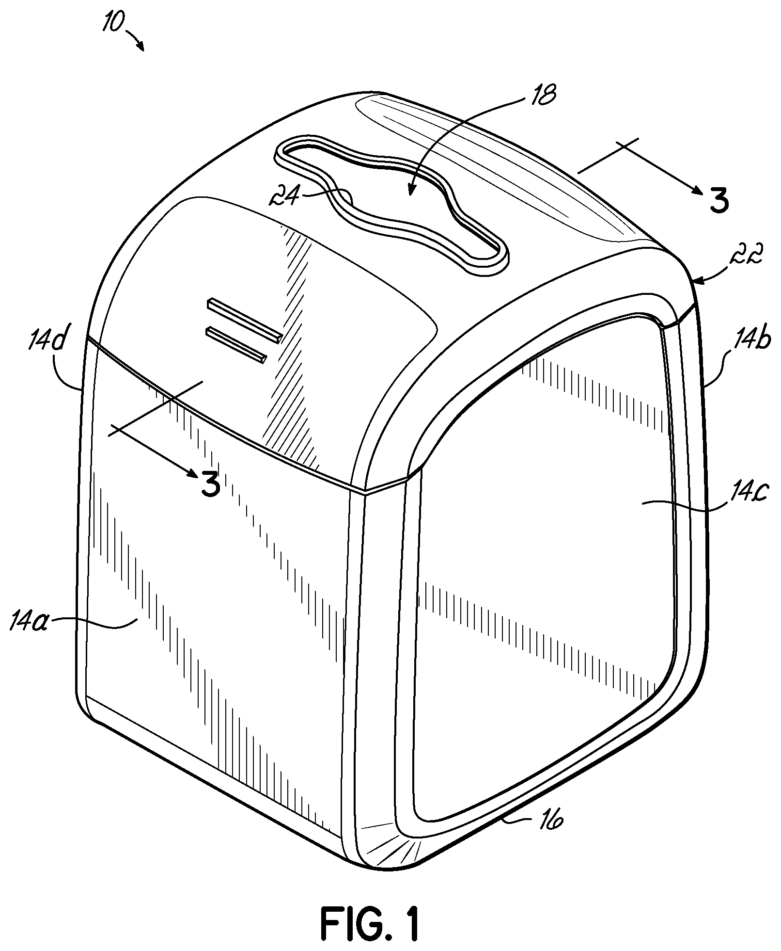
FIG. 1 is a perspective view of a dispenser for storing and dispensing individual paper units from a stack of such paper units in accordance with one embodiment of the invention.
FIG. 2 is a perspective view of a stack of individual paper units in accordance with one embodiment of the invention.
FIG. 3 is a cross-sectional view of the dispenser of FIG. 1 taken generally along line 3-3 of FIG. 1.
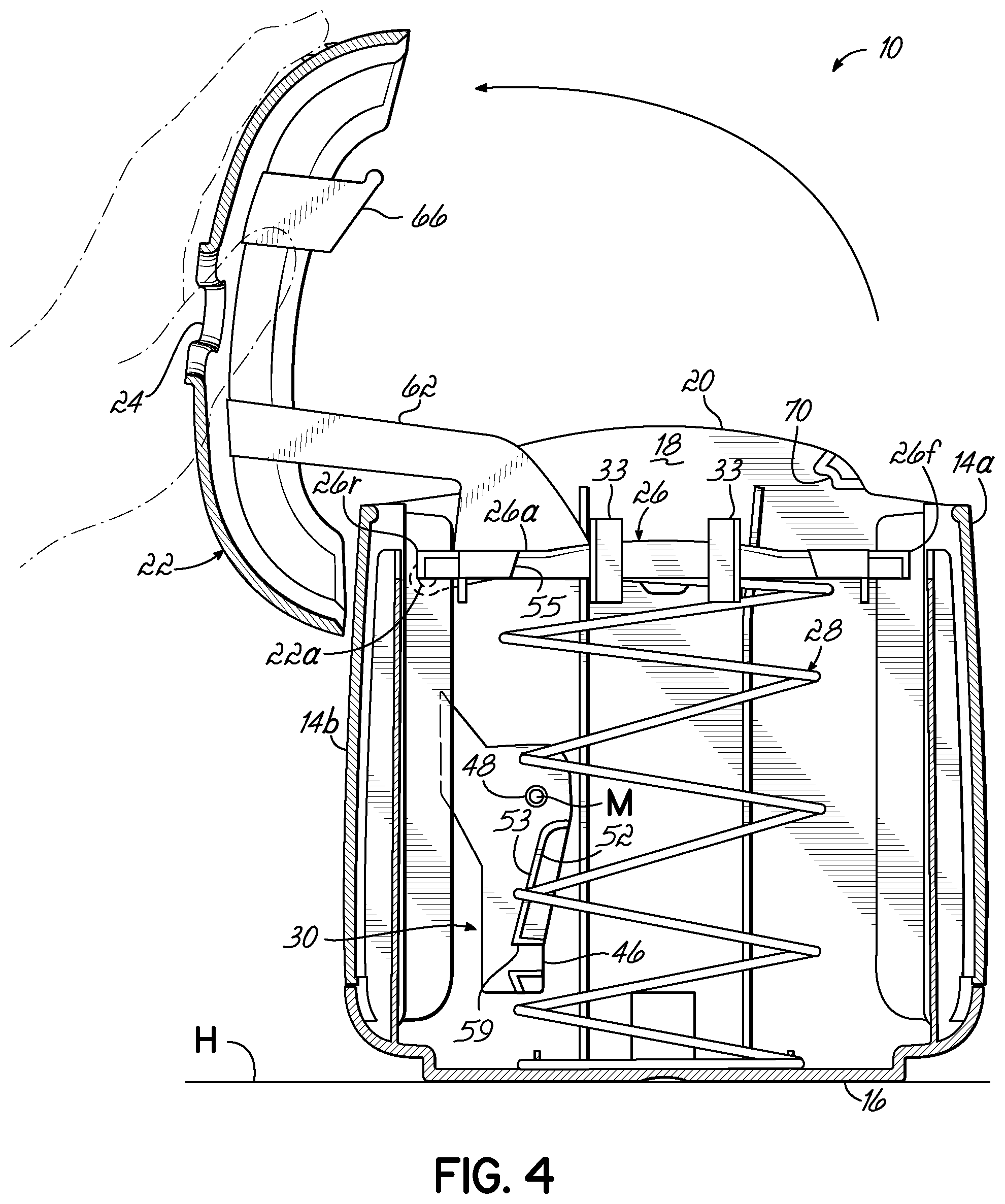
FIG. 4 is a view similar to FIG. 3, showing a lid of the dispenser in an open position.
FIG. 5 is a view similar to FIGS. 3 and 4, showing a platen of the dispenser in a locked position and schematically showing the stack of FIG. 2 in an interior volume of the dispenser.
FIG. 5A is a view similar to FIG. 5, showing the platen of the dispenser in an unlocked position and schematically showing the stack of FIG. 2 in the interior volume of the dispenser.
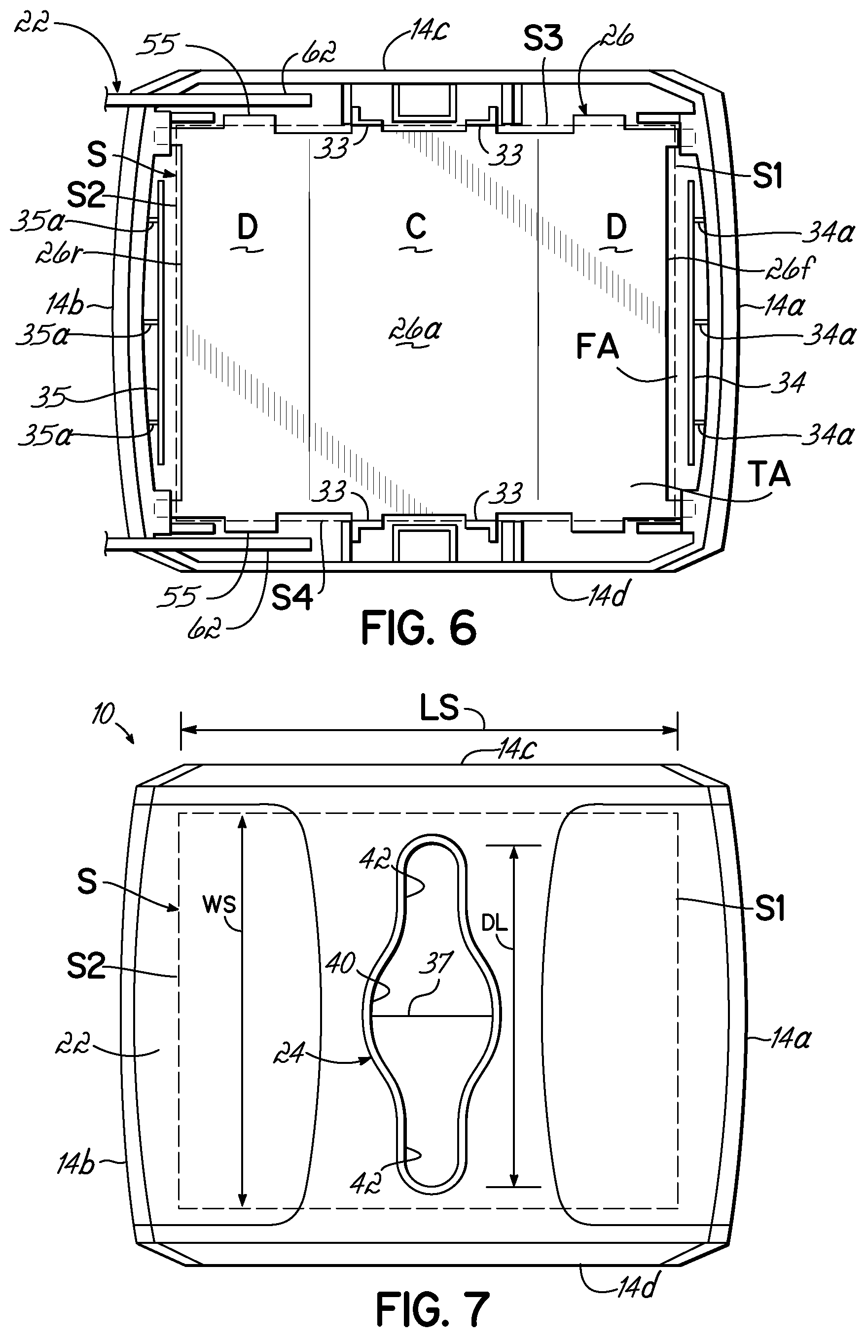
FIG. 6 is a partial, top view of the dispenser in FIGS. 1 and 3-5, with the lid of the dispenser in an open position and showing a top, paper-engaging surface of the platen of the dispenser, as well as a stack (schematically) resting on that surface.
FIG. 7 is a top view of the dispenser of FIGS. 1 and 3-6, with the lid of the dispenser in a closed position and a stack in the interior volume of the dispenser.
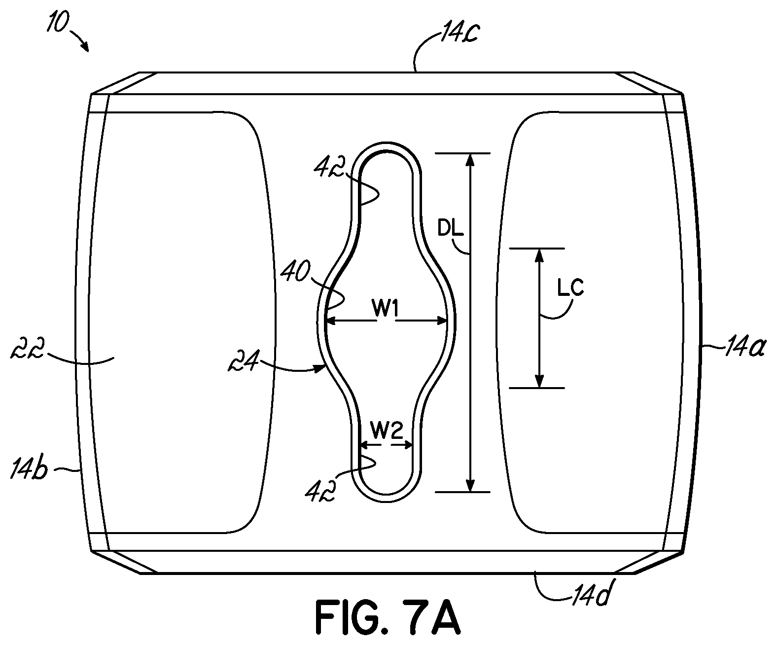
FIG. 7A is another top view of the dispenser of FIGS. 1 and 3-6, showing additional features of that dispenser.
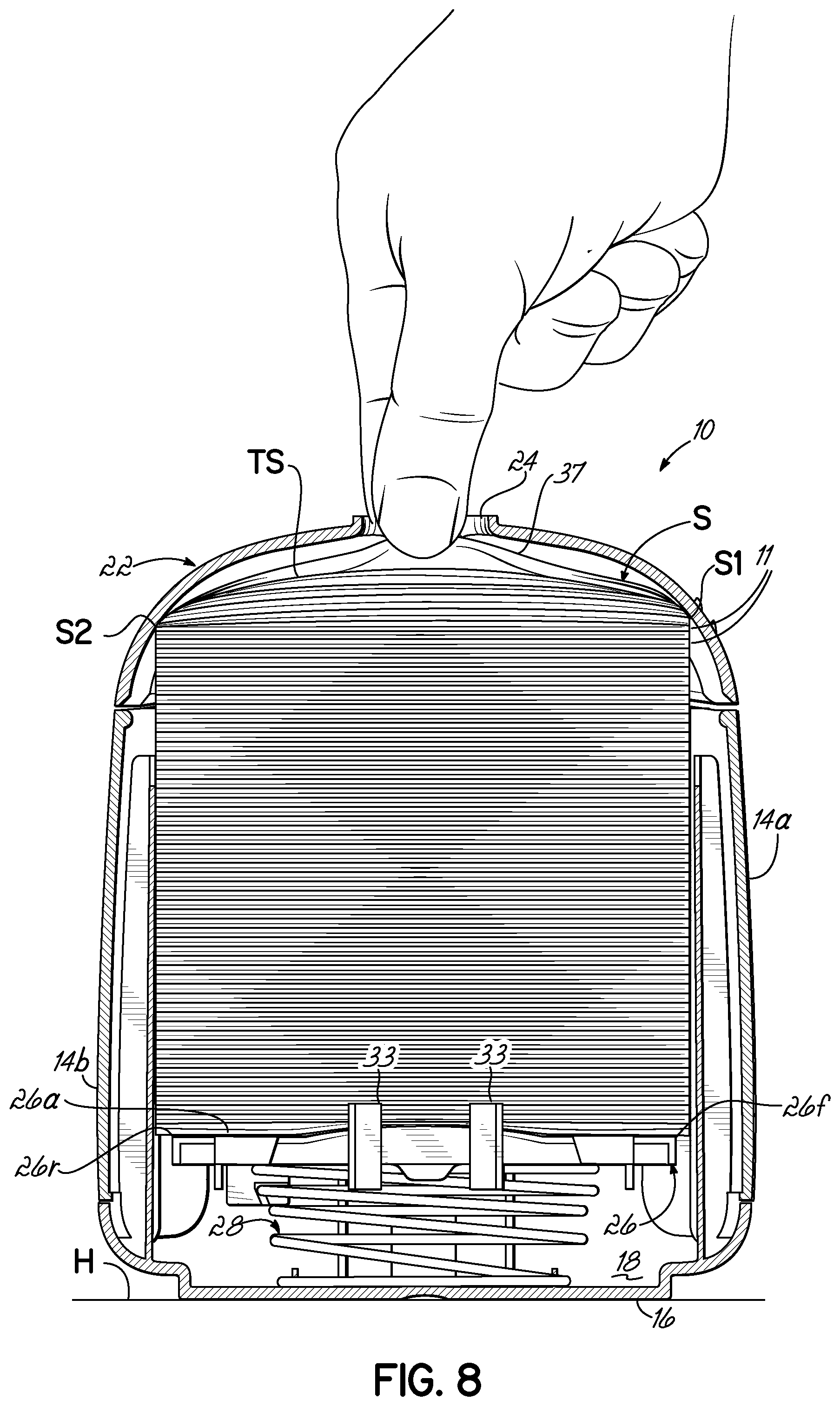
FIG. 8 is a view similar to FIGS. 3-5, showing a stack in the interior volume of the dispenser and extraction of a portion of a topmost paper unit of that stack through a dispensing aperture of the dispenser.
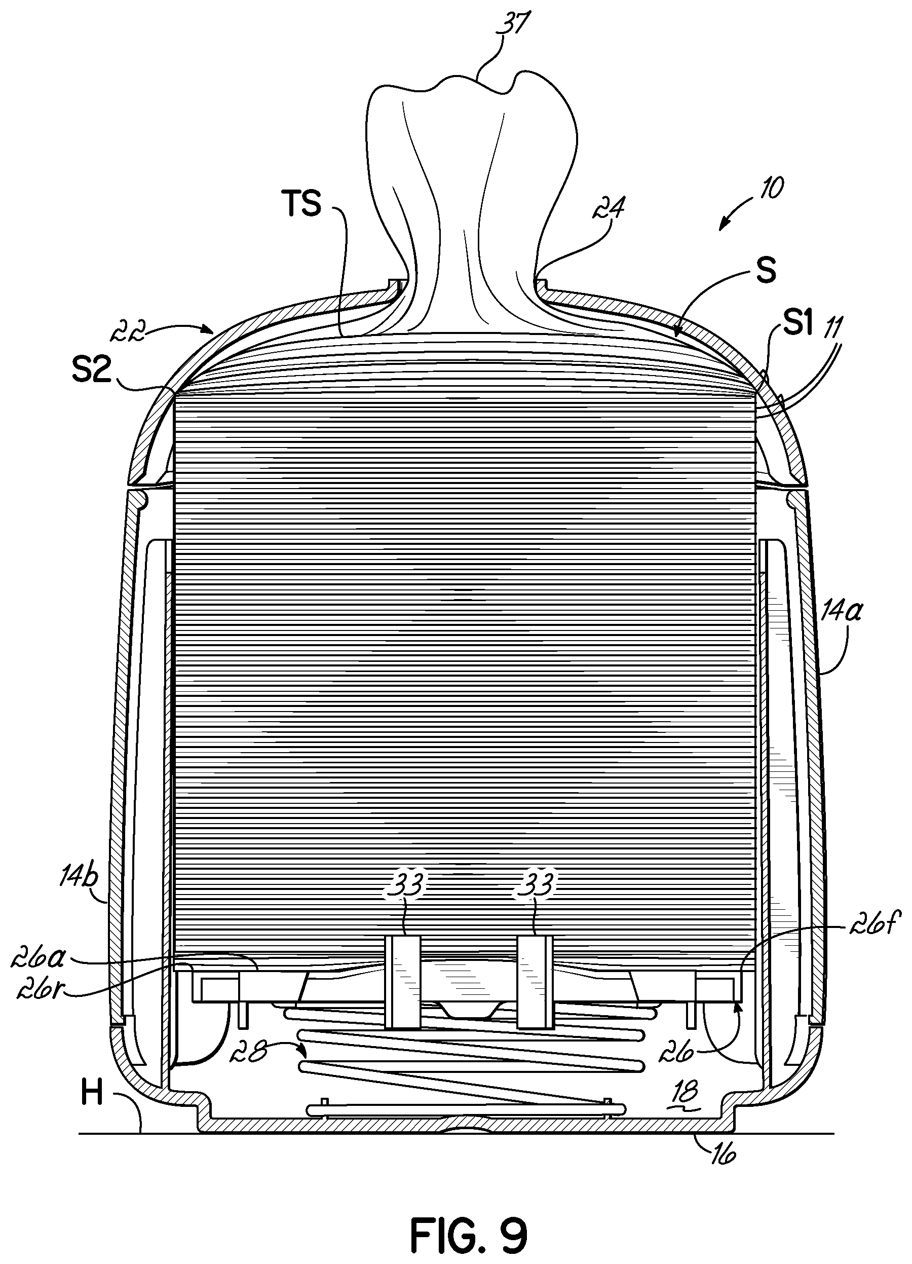
FIG. 9 is a view similar to FIG. 8, showing the stack of individual paper units ready for dispensing.
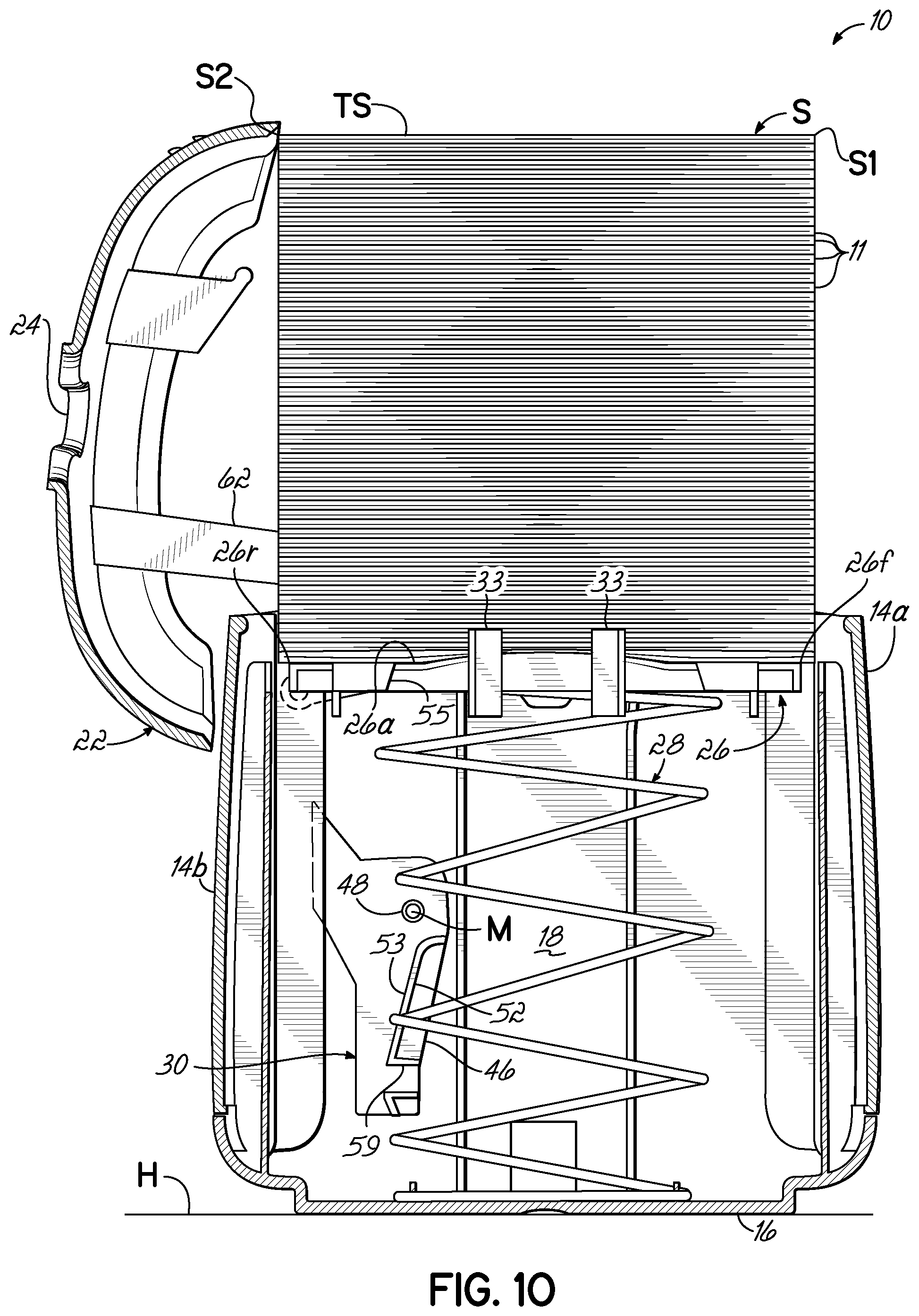
FIG. 10 is a view similar to FIGS. 3-5, 8, and 9, showing a stack of individual paper units being loaded into the interior volume of the dispenser.
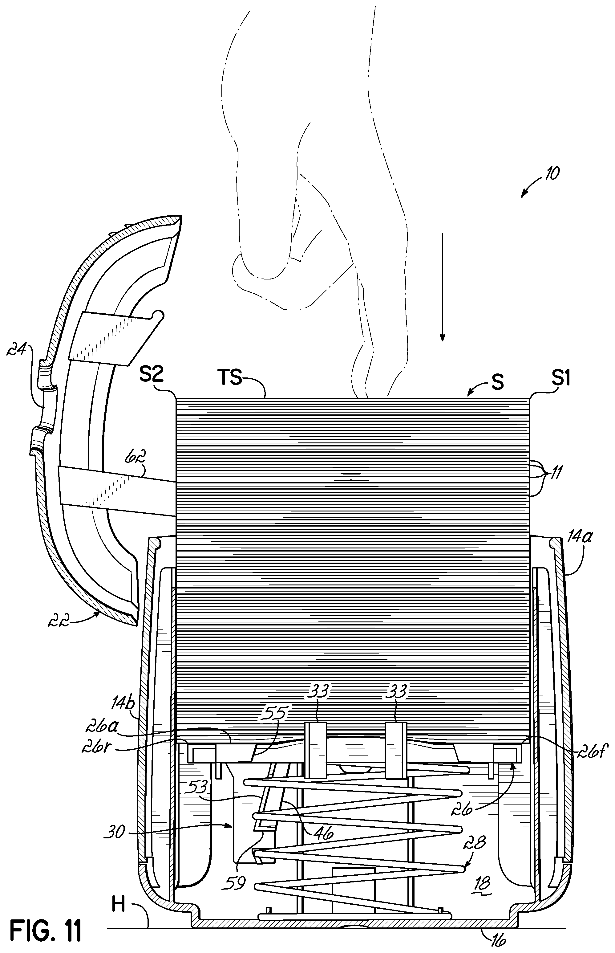
FIG. 11 is a view similar to FIGS. 3-5 and 8-10, showing the stack continuing to be loaded into the interior volume of the dispenser.
FIG. 12 is a view similar to FIGS. 3-5 and 8-11, schematically showing the stack in a position within the dispenser different from the positions of that stack in FIGS. 10 and 11.
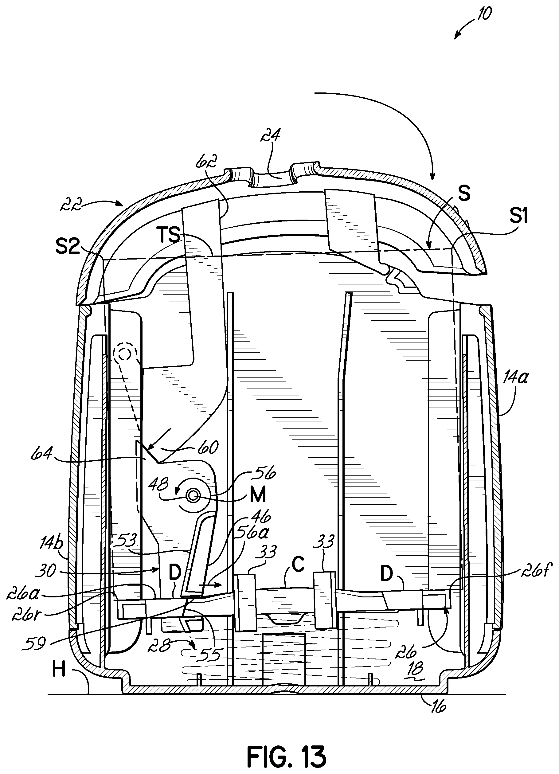
FIG. 13 is a view similar to FIGS. 3-5 and 8-12, showing closing of the lid of the dispenser with the stack (schematically shown) in the interior volume of that dispenser.
FIG. 14 is a view similar to FIGS. 3-5 and 8-13, with the lid of the dispenser in a closed position.
DETAILED DESCRIPTION OF PARTICULAR EMBODIMENTS
To the extent that any meaning or definition of a term in this written document conflicts with any meaning or definition of the term in a document incorporated by reference, the meaning or definition assigned to the term in this written document shall govern. Also, it is to be understood that the phraseology and terminology used herein is for the purpose of description and should not be regarded as limiting. The use of "including," "comprising," or "having" and variations thereof herein is meant to encompass the items listed thereafter and equivalents thereof as well as additional items. Unless specified or limited otherwise, the terms "mounted," "connected," "supported," and "coupled" and variations thereof are used broadly and encompass both direct and indirect mountings, connections, supports, and couplings. Further, "connected" and "coupled" are not restricted to physical or mechanical connections or couplings. Also, as used herein, the term "releasable coupling" and related terms refer to a type of coupling in which the coupled structures may be readily detached, decoupled, or otherwise separated from one another in a simple manner and without causing the destruction or damage of any of those structures. For sake of further explanation, a permanent--rather than "releasable"--type of coupling may refer, for example, to two structures that are integrally formed with one another, or which are adhesively attached, such that their separation would necessarily result in at least some level of damage to one or more of the parts being separated.
With reference to the figures, and more particularly to FIGS. 1, 2, 3, 4, and 5, an illustrative apparatus in the form of a dispenser 10 is shown for dispensing individual paper units such as napkins 11 from a stack S of those napkins 11 (FIG. 2). While the description herein refers to the individual paper units as napkins, it is contemplated that other types of paper units such as facial tissue or hand towel sheets may be used in the manner described herein and are therefore considered to fall within the scope of the present disclosure. As shown particularly in FIGS. 1 and 3-5, dispenser 10 is made up of a plurality of sidewalls, which include--with respect to the orientation in the illustrative figures--a front wall 14a, a rear wall 14b disposed opposite front wall 14a, and two lateral walls 14c, 14d that extend between the front and rear walls 14a, 14b. A bottom wall 16 of dispenser 10 spans the space between sidewalls 14a, 14b, 14c, and 14d and jointly with those sidewalls defines an interior volume 18 of dispenser 10, suitable to store a stack S of napkins 11 for dispensing of those napkins to the exterior of dispenser 10.
Bottom wall 16 is a generally planar structure and is configured to rest on a generally horizontal surface H, such as a countertop, and in that regard may include one or more feet (not shown) on its exterior-facing surface. Sidewalls 14a, 14b, 14c, 14d jointly define a top opening 20 (FIG. 4) of dispenser 10 into the interior volume 18 of that dispenser. A lid 22 of dispenser 10 is hingedly coupled to lateral walls 14c, 14d for pivoting motion of that lid 22 about a lid axis 22a, between a closed position substantially preventing access into interior volume 18 (FIGS. 1 and 3), and a fully opened position providing such access (FIGS. 4 and 5). Lid 22 includes a dispensing aperture 24 that allows napkins 11 in the interior volume 18 to be dispensed to the exterior, for example one by one (i.e., one at a time). As more fully explained below, dispensing aperture 24 is configured to limit contact of the napkins 11 in interior volume 18 with human fingers, thereby minimizing the likelihood of contamination of napkins 11.
Dispenser 10 also includes a movable platen 26 in its interior volume 18, that is urged upwardly by a biasing element such as a compression spring 28 that is coupled at one end to the interiorly-facing side of bottom wall 16, and at the other end to an underside of platen 26. Platen 26 is movable between a bottom-most position associated with maximum compression of spring 28, and a top-most position at which platen 26 is adjacent top opening 20 of dispenser 10 and associated, in specific embodiments, with an uncompressed state of spring 28. Other embodiments are contemplated in which a different type of biasing element is used, which may be another type of spring, such as a leaf spring or another type of spring, or some other element having resilient properties (e.g., a compressible rubber ball).
With continued reference to FIGS. 1-5, platen 26 includes a paper-engaging top surface 26a that is configured to support, from the bottom, a stack S of the napkins 11. When the dispenser 10 is full of napkins 11, the platen 26 may be at the bottom-most position of that platen 26, which defines the tallest stack of napkins that will effectively fit in interior volume 18 while being supported by paper-engaging surface 26a, or somewhere short of that bottom-most position. The bottom-most position of platen 26, in the illustrated embodiment, may be associated with the state of generally maximum or near maximum compression of spring 28. With particular reference to FIG. 5, platen 26 has a locked position P, proximate bottom wall 16, that is short of the bottom-most position of platen 26, which allows dispenser 10 to accommodate more napkins 11 than is apparent from the locked position P of the platen 26. In the locked position P, platen 26 is unable to move upward unless a locking mechanism 30 of dispenser 10 is disengaged from platen 26.
Notably, at position P, the paper-engaging surface 26a is oriented obliquely relative to bottom wall 16, and also relative to the horizontal surface H on which dispenser 10 rests, which effectively causes a top surface TS of stack S to similarly be obliquely oriented. The inventors have identified an oblique orientation of top surface TS to be particularly advantageous to prevent overstuffing of dispenser 10 with napkins 11, which is desirable to prevent malfunction of dispenser 10. As shown in the figures, the oblique orientation of top surface TS is such that a front edge S1 of top surface TS, which is closer to the person loading dispenser 10 with napkins 11 (adjacent the top of front wall 14a of dispenser 10), is higher than oppositely disposed rear edge S2 of top surface TS in the locked position P of platen 26.
The relatively higher level of front edge S1--relative to the opposite rear edge S2 of top surface TS--provides the person loading the stack into dispenser 10 with a perception of having filled dispenser 10 to capacity or beyond capacity. This perception, accordingly, minimizes the likelihood of overstuffing the dispensers with additional napkins, compared to a hypothetical substantially horizontal orientation of top surface TS, which would lead that person to believe that more napkins 11 can fit in interior volume 18. Minimization of overstuffing protects the moving components of dispenser 10 from malfunctioning, and provides for reliable, consistent dispensing without tearing of the napkins 11 as they are extracted through aperture 24.
On the other hand, the oblique orientation of top surface TS may undesirably concentrate the force exerted by stack S--during dispensing--against one of the edges of dispensing aperture 24, rather than uniformly across all edges defining such aperture 24. If the quality of paper from which napkins 11 are made is low, that uneven concentration of forces against aperture 24 may cause the paper napkins 11 to tear during dispensing, which would be detrimental to the experience by the end user of the dispenser. Additionally, the oblique orientation of top surface TS may provide the person loading the dispenser the false impression that something is broken in dispenser 10, which may lead to undesirable manipulation of the components of dispenser 10. That undesirable manipulation may ultimately lead to failure of those components. The oblique orientation of stack S, as a whole, may also be detrimental in cases in which the substrate making up the napkins 11 has a low friction, which may cause the stack S to become destabilized and slide or collapse during loading or during use.
The angle of orientation of paper-engaging surface 26a relative to bottom wall 16 and also relative to the horizontal surface H on which dispenser 10 rests--in specific embodiments--may be between about 3 and about 20 degrees, specifically between about 3 and about 15 degrees, and more specifically between about 5 and about 10 degrees. One suitable angle of orientation for paper-engaging surface 26a, for example, may be about 7 degrees. An angle of about 7 degrees has been found to provide the right balance between providing the desired effect described in the preceding paragraph, while preventing or at least minimizing the likelihood of collapse of a stack S within dispenser 10, particularly for stacks S made up of napkins made of a material having a low coefficient of friction. For napkins made of materials having a relative high coefficient of friction, accordingly, an angle greater than about 10 degrees and as high, for example, as about 20 degrees may be used.
With continued reference to FIGS. 1-5, and further referring to FIG. 6, the platen 26 not only provides the oblique orientation of paper-engaging surface 26a as described above, but it is also configured to minimize lateral movement of the stack S in interior volume 18 i.e., movement toward and away from the lateral walls 14c, 14d. More specifically, platen 26 includes a plurality of tabs 33 protruding upwardly from the side edges of platen 26, and which are configured to laterally support stack S. Further, dispenser 10 includes a pair of upright, flat supports 34, 35 respectively adjacent front and rear walls 14a, 14b, and which are connected to those walls 14a, 14b through respective sets of ribs 34a, 35a that conform--in the example embodiment of the figures--to the arcuate shape (when seen from above) of front and rear walls 14a, 14b. Flat supports 34, 35 provide support to stack S, preventing forward and backward movement (i.e., respectively toward front and rear walls 14a, 14b) of stack Sin interior volume 18.
Jointly, the lateral distance between the inward-facing surfaces of tabs 33, and the longitudinal distance between the inner-facing surfaces of flat supports 34, 35 define a total effective support area TA of paper-engaging surface 26a available to support a stack S. The stack S of napkins 11, in that regard, is designed so that a footprint area FA of that stack S closely matches the total area TA, so as to minimize undesirable lateral or longitudinal movement of stack S within dispenser 10 while stack S is stored in interior volume 18, and particularly during dispensing. The relatively close match between areas TA and FA advantageously facilitates portability of a dispenser 10, loaded with napkins 11 in its interior volume 18. Specifically, the relatively close match between areas TA and FA allow a preloaded dispenser to be moved, for example, from one table of a restaurant to another, with little concern for collapsing of the stack within dispenser 10, which would otherwise potentially be detrimental to the napkin-dispensing operation.
For example, the ratio of the footprint area FA of stack S to the total effective area TA may be in the range between about 0.7 and about 1.0, or specifically in the range between about 0.85 and about 1.0, or more specifically, in some embodiments, in the range between about 0.95 and about 1. A ratio of at least about 0.7 may suffice to provide the desired level of lateral and longitudinal support to stack S for napkins made of a substrate having relatively high coefficient of friction values (i.e., friction between adjacent napkins). That ratio, however, may not suffice for napkins 11 having a lower coefficient of friction value, in which case a ratio of at least about 0.85 may be required in order to properly support a stack S in interior volume 18. A ratio of at least about 0.95 is superior in that proper support of stack S is attainable without much concern for the coefficient of friction value of the napkins 11. It is understood, however, that higher ratios may require low tolerances in the manufacturing process for napkins 11, which is typically attained with more complex (and costlier) manufacturing processes. In other words, if the target is to attain a ratio of about 1, for example, the manufacturing process for the stack S of napkins 11 would require that all napkins are perfectly aligned with one another in the stack S and that the width and length of the stack do not exceed the limit provided by the spacing provided by the inward-facing surfaces of support tabs 33 and flat supports 34, 35.
The close match between the footprint area FA of stack S and the total effective area TA of paper-engaging surface 26a offers an additional advantage. That close match also results in minimization of the space between the stack S and the sidewalls 14a, 14b, 14c, 14d, which reduces the volume available for debris and other types of contaminants to accumulate in interior volume 18. That, in turn, reduces the likelihood of malfunction of the dispenser 10, particularly over an extended period of time, thereby lengthening the useful life of dispenser 10.
With continued reference to FIGS. 1-6, and particularly referring to FIG. 2, the stack S of napkins 11, in the example embodiment shown in that figure, is made of a plurality of napkins 11 that are interfolded (i.e., interleaved), such the pulling of one napkin 11 though dispensing aperture 24 is effective to pull the next napkin in the stack S through frictional engagement between adjacent, interfolded napkins. Stack S in the illustrative embodiment of FIG. 2 has a number of Z-folded napkins 11 in a number of about 120, although other types of folds and/or a different number of napkins are similarly contemplated. The footprint area FA of that stack S (FIG. 6) is generally rectangular and may be such that the length LS and width WS of stack S do not exceed, respectively, about 115 mm and about 95 mm, which respectively correspond to the longitudinal distance between the inward-facing surfaces of flat supports 34, 35 and the lateral distance between the inward-facing surfaces of support tabs 33. In one example embodiment, the length LS and width WS of stack S are respectively about 107 mm and 84 mm. Stack S has a height HS that may, for example, be no greater than about 110 mm, which is a height that has been found to yield a stack with a suitable number of napkins S and which prevents overstuffing of the dispenser 10 beyond its intended capacity.
The example stack S of FIG. 2 has a generally rectangular cross-section such that the top surface TS defines a first pair of oppositely disposed, parallel surface edges S1, S2, and a second pair of oppositely disposed surface edges S3, S4, which are also parallel to one another. In this embodiment, accordingly, the surface edges S1, S2 of the first pair are generally orthogonal to the surface edges S3, S4 of the second pair. In the example stack S of FIG. 2, each of the napkins 11 is folded in such a manner that the top surface TS is provided with a generally linear gripping tab 37 that is generally parallel to the second pair of surface edges S3, S4 and which extends between the first pair of surface edges S1, S2. In the illustrative stack S of the figures, the gripping tab 37 is located centrally between the second pair of surface edges S3, S4, although alternative stacks are contemplated in which the gripping tab 37 is not centrally located between surface edges S3, S4 (i.e., it may be located closer to surface edge S3 than it is to surface edge S4 or vice versa), or in which the gripping tab 37 has shape other than that shown (e.g., a non-linear tab). Yet other alternative stacks are contemplated having no gripping tab 37 at all.
With continued reference to FIGS. 1-6, and further referring to FIGS. 7, 7A, 8, and 9, the centralized location and shape of gripping tab 37 in the example stack S of the figures advantageously cooperate with the shape of dispensing aperture 24 to facilitate loading of the stack S into dispenser 10 for dispensing of the napkins 11 from stack S. Specifically, the stack S is loaded into the interior volume 18 of dispenser 10 and the lid 22 pivotally moved to the closed position. The person loading the dispenser 10 may then be able to pinch the gripping tab 37 using the thumb and forefinger, and extend the gripping tab 37 through the dispensing aperture 24 toward the exterior, thereby making the napkins 11 available for dispensing (FIGS. 8 and 9). To that end, the stack S may be loaded into interior volume 18 in an orientation such that the longitudinal dimension of gripping tab 37 is oriented transversely to the length dimension of dispensing aperture 24, as shown in FIG. 7. The shape and dimensions of dispensing aperture 24 are configured for that type of operation, thereby favoring stacks with a gripping tab--if one is present in the stack S--shaped and located as in the illustrated embodiment, while at least hindering the loading of stacks S having no gripping tab 37 at all or having a gripping tab located outside a centrally located section ("central section") 40 of dispensing aperture 24.
More specifically, each of a pair slotted sections 42 extending from central section 40 has a width W2 that the inventors have found to be sufficiently narrow to prevent the average human adult forefinger and thumb from accessing interior volume 18 through those slotted sections 42. The width W2 of the slotted sections may for example be no greater than about 13 mm, and more specifically less than about 12 mm, and in some embodiments between about 10 and about 11 mm. The relatively small width W2 prevents an average-sized adult human forefinger and thumb from accessing the top surface TS of stack S, which minimizes the likelihood of contamination of the stack S in interior volume 18, yet allows each napkin to protrude ready for dispensing in a semi-opened state, as shown in FIG. 9, for example. The small width W2 of the slotted sections 42, additionally, makes it difficult for the topmost napkin 11 in the stack S to be grabbed and pulled through dispensing aperture 24, unless that napkin 11 is grabbed through the central section 40. To that end, the absence of a gripping tab 37, particularly in stacks S having napkins with high coefficient of friction values, creates difficulty in the ability to grab the topmost napkin 11 and extend at least a portion of that napkin through aperture 24. Napkins with a relatively low coefficient of friction value, conversely, may not require a gripping tab at all, insofar as the topmost napkin 11 may be easy to slide relative to adjacent napkins, thereby allowing the user to grab that topmost napkin and extend at least a portion of that napkin through dispensing aperture 24.
Other aspects of the shape of dispensing aperture 24 are similarly designed to provide specific advantages to embodiments having such shape of dispensing aperture. For example, the overall length DL of the dispensing aperture 24 (i.e., the dimension spanning the space between lateral walls 14c, 14d) is configured to be less than the expected width WS of the stack S (i.e., the dimension of the stack parallel to the length dimension of the dispensing aperture 24). That feature forces the topmost napkin 11 protruding through dispensing aperture 24 to bend slightly, thereby attaining an upright attitude, ready for withdrawal by a user, as shown in FIG. 9. The overall length DL, for example, may be about 77 mm, which is a dimension suitable for stacks having a width WS of about 84 mm--with that combination of dimensions having been found to facilitate upright standing of certain types of napkins 11 through dispensing aperture 24, while allowing for smooth, consistent dispensing of those napkins 11. The precise suitable combination of length DL and width WS may depend on the coefficient of friction value of the napkins 11.
Additionally, the length LC and width W1 of the central section 40 are configured to allow an average adult human thumb and forefinger to pinch the gripping tab 37, in the manner shown in FIG. 8, while minimizing the overall area of that central section 40. In that regard, the length LC of central section 40 may for example be no greater than about 40 mm, while the width W1 of that central section 40 may for example be no greater than about 30 mm. Minimization of the overall area of central section 40, in turn, advantageously minimizes exposure of the napkins 11 in interior volume 18 to the exterior through dispensing aperture 24, which in turn reduces the likelihood of contamination of those napkins 11. A disadvantage of the relative small size of central section 40, however, is that it may impede or at least hinder the pinching or otherwise grabbing of a portion of the topmost napkin 11 in the stack S during loading, and specifically during preparation of the stack S for dispensing, particularly--for example--for persons having above-average sized fingers.
With continued reference to FIGS. 3-5, 8, and 9, and further referring to FIGS. 10, 11, 12, 13, and 14, dispenser 10 has a pair of locks 46, jointly making up locking mechanism 30, and which are respectively coupled to each of the lateral walls 14c, 14d. Locks 46 are effective to selectively immobilize platen 26 in the locked position P of that platen 26 (FIG. 5) during loading of the stack S into the interior volume 18. Immobilization of platen 26 during loading of stack S facilitates the loading operation, such as by permitting a single-handed loading operation. For ease of explanation and understanding, the following lines describe the structure and operation of one of those two locks 46, being understood that the same principles and description apply similarly to the other one of the locks 46. Each lock 46 is pivotally coupled to an interior-facing surface of one of the lateral walls 14c, 14d at pivoting location M. A torsion spring 48 at location M urges a bottom portion of lock 46 in a biased direction 50 (FIG. 5), toward the rear wall 14b of dispenser 10, although it is understood that alternative embodiments may use other types of biasing element, whether at location M or at another location associated with lock 46, yet being effective to urge the lock in the biased direction 50.
Lock 46 includes a ramp 52 having a ramp surface 53, that is engageable by a cooperating laterally protruding wing 55 of platen 26 as platen 26 moves downward, toward the bottom wall 16. As seen in FIG. 5A and sequentially in FIGS. 10-12, as the platen 26 moves downward by action of a user pushing down on the stack S supported by paper-engaging surface 26a of platen 26, wing 55 engages ramp surface 53 (FIG. 12). Continued downward movement of platen 26 causes pivoting movement of the bottom portion of lock 46 in a second direction 56, toward front wall 14a, opposing the urging force exerted by torsion spring 48 in the biased direction 50. Once the platen 26 reaches a position in which wing 55 no longer engages ramp surface 53, torsion spring 48 causes the bottom portion of lock 46 to snap back and pivotally move in the biased direction 50, toward the rear wall 14b of dispenser 10 (FIG. 13). At the same time, compression spring 28 pushes platen 26 upward, toward the top opening 20 of dispenser 10, with the force exerted by spring 28 pinning wing 55 against a bent end section 59 of ramp 52. The immobilized position of platen 26 at its locked position (i.e., position P, FIG. 5) is configured to orient the platen 26 obliquely, with a front edge 26f of paper-engaging surface 26a being higher than rear edge 26r of surface 26a. That oblique orientation or paper-engaging surface 26a, in turn, results in a similar orientation of the top surface TS of stack S, with the associated advantages described above.
In operation, once the stack S has been loaded into interior volume 18 of dispenser 10, the person preparing the stack S for dispensing pivotally moves the lid 22 toward the closed position, as shown in FIG. 13. As that movement occurs, a distal end 60 of a support arm 62 of lid 22 engages a cooperating top end or cam 64 of lock 46, located above pivoting location M. With continued movement of lid 22 toward the closed position, the engagement of distal end 60 with cam 64 again causes pivoting movement of the bottom portion of lock 46 in the second direction 56, opposing the urging force exerted by torsion spring 48. Arrow 56a in FIG. 13 shows the direction of motion of the bottom portion of lock 46 associated with the pivoting movement of lock 46 in the second direction 56. Pivoting movement of the bottom portion of lock 46 in that second direction 56, in turn, results in disengagement of wing 55 of platen 26 from the bent end section 59 of ramp 52. That disengagement allows the platen 26 to pop toward top opening 20, by action of compression spring 28, which is effective to push the stack S against the underside of lid 22, and more specifically against dispensing aperture 24 (FIG. 14). FIGS. 6, 13, and 14 show paper-engaging surface 26a having a central section C that is bowed or curved (i.e., convex as seen from above), and two substantially planar end sections D. The bowed or curved and shape of central section C substantially matches the concave shape of the underside of lid 22. This feature provides a more uniform force exerted on the topmost napkin 11 in the stack by engagement with the underside of lid 22, as compared, for example, to a hypothetical entirely planar paper-engaging surface 26a. The relative uniform force exerted on the topmost napkin 11 enhances the dispensing experience, by requiring a relative low force to be exerted by the user in pulling such napkin toward the exterior of dispenser 10.
A contemplated method of loading and dispensing paper such as napkins 11 from a stack S of those napkins 11 accordingly includes unlocking the lid 22 from its closed position by exerting a force on the lid 22, relative to a remainder of dispenser 10, directed generally toward the rear wall 14b and lid axis 22a, and generally along a plane defined by top opening 20. That exerted force disengages a pair of locking lid tabs 66 of lid 22 from a pair of cooperating detents 70 located on the lateral walls 14c, 14d of dispenser 10, thereby allowing pivoting movement of lid 22 toward the open position of lid 22 (FIG. 4). This example method of unlocking lid 22 is advantageous in that same does not require the unnecessary bending of the sidewalls, which would ultimately likely lead to deformation or breaking of the dispenser. On the other hand, that method of unlocking requires the use of two hands (one hand to hold the lateral walls 14c, 14d, and one to push on lid 22 toward rear wall 14b), which may be undesirable in cases in which a one-hand opening operation is desired.
A contemplated loading operation includes unlocking lid 22 of dispenser 10 in the manner described above, opening the lid 22 by pivoting same about lid axis 22a toward the open position of the lid 22 (FIG. 4), and inserting the stack S of napkins 11 through top opening 20 into the interior volume 18 of the dispenser 10 (FIG. 10). The stack S is placed on the paper-engaging surface 26a of platen 26, for example using only one hand, and further so that the gripping tab 37 of the top-most napkin 11 of stack S, if present, is oriented to extend between front and rear walls 14a, 14b i.e., generally orthogonal to the length dimension of the dispensing aperture 24 when lid 22 is in its closed position (FIG. 7). The person loading the stack S then exerts a downward force on the stack S (FIGS. 11 and 12), thereby pushing the platen 26 in the same direction until the platen 26 is locked at position P (FIG. 5) by the locks 46 of locking mechanism 30. As stated above, in the locked position of platen 26, which corresponds to a locked condition of locking mechanism 30, the paper-engaging surface 26a of platen 26 attains an oblique orientation relative to the bottom wall 16 of dispenser 10 and also relative to the generally horizontal surface H on which dispenser 10 rests.
Upon cessation of the exertion of the downward force upon stack S, the person loading the stack S proceeds to pivot the lid 22 toward the closed position (FIG. 13), with that pivoting motion of lid 22 being effective to disengage locking mechanism 30 from the platen 26, thereby permitting platen 26 to pop up, by action of compression spring 28, toward top opening 20. Upon full closure of lid 22 (FIG. 14), the person loading the stack S inserts the thumb and forefinger through central section 40 of dispensing aperture 24. That person then pinches gripping tab 37--if present--and pulls the portion of the topmost napkin 11 defining gripping tab 37 through central section 40, toward the exterior (FIG. 8). Alternatively, before fully closing lid 22, the user may grip any portion of the topmost napkin 11 in stack S toward the underside of lid 22 and through central section 40, toward the exterior of dispenser 10, and then proceed to fully close lid 22. Once a portion of the topmost napkin 11 protrudes through dispensing aperture 24, the napkins 11 are ready for continuous dispensing.
From the above disclosure of the general principles of the present invention and the preceding detailed description of exemplifying embodiments, those skilled in the art will readily comprehend the various modifications to which this invention is susceptible. Accordingly, this invention is intended to be limited only by the scope of the following claims and equivalents thereof.
* * * * *
D00000
D00001
D00002
D00003
D00004
D00005
D00006
D00007
D00008
D00009
D00010
D00011
D00012
D00013

D00014
D00015

XML
uspto.report is an independent third-party trademark research tool that is not affiliated, endorsed, or sponsored by the United States Patent and Trademark Office (USPTO) or any other governmental organization. The information provided by uspto.report is based on publicly available data at the time of writing and is intended for informational purposes only.
While we strive to provide accurate and up-to-date information, we do not guarantee the accuracy, completeness, reliability, or suitability of the information displayed on this site. The use of this site is at your own risk. Any reliance you place on such information is therefore strictly at your own risk.
All official trademark data, including owner information, should be verified by visiting the official USPTO website at www.uspto.gov. This site is not intended to replace professional legal advice and should not be used as a substitute for consulting with a legal professional who is knowledgeable about trademark law.