Light emitting device
Shimonishi , et al. April 13, 2
U.S. patent number 10,978,619 [Application Number 15/827,412] was granted by the patent office on 2021-04-13 for light emitting device. This patent grant is currently assigned to TOYODA GOSEI CO., LTD.. The grantee listed for this patent is TOYODA GOSEI CO., LTD.. Invention is credited to Yukihiro Demukai, Daisuke Kato, Tomohiro Miwa, Ikuhiro Oya, Satomi Seki, Shota Shimonishi, Shigeo Takeda, Shota Yamamori.


| United States Patent | 10,978,619 |
| Shimonishi , et al. | April 13, 2021 |
Light emitting device
Abstract
A light emitting device includes a light emitting element that emits a light having a peak emission wavelength in a wavelength range of not less than 410 nm and not more than 425 nm, and a phosphor emitting a fluorescence having a peak at a longer wavelength side than the peak emission wavelength of light emitted from the light emitting element. A general color rendering index Ra of fluorescence emitted from the phosphor is not less than 95. A general color rendering index Ra of mixed light of light emitted from the light emitting element and fluorescence emitted from the phosphor is higher than a general color rendering index Ra of fluorescence emitted from the phosphor. A color rendering index Rf of the mixed light is not less than 96.
| Inventors: | Shimonishi; Shota (Kiyosu, JP), Miwa; Tomohiro (Kiyosu, JP), Seki; Satomi (Kiyosu, JP), Kato; Daisuke (Kiyosu, JP), Takeda; Shigeo (Kiyosu, JP), Yamamori; Shota (Kiyosu, JP), Demukai; Yukihiro (Kiyosu, JP), Oya; Ikuhiro (Kiyosu, JP) | ||||||||||
|---|---|---|---|---|---|---|---|---|---|---|---|
| Applicant: |
|
||||||||||
| Assignee: | TOYODA GOSEI CO., LTD. (Kiyosu,
JP) |
||||||||||
| Family ID: | 1000005487131 | ||||||||||
| Appl. No.: | 15/827,412 | ||||||||||
| Filed: | November 30, 2017 |
Prior Publication Data
| Document Identifier | Publication Date | |
|---|---|---|
| US 20180158994 A1 | Jun 7, 2018 | |
Foreign Application Priority Data
| Dec 2, 2016 [JP] | JP2016-234940 | |||
| Apr 14, 2017 [JP] | JP2017-080904 | |||
| Current U.S. Class: | 1/1 |
| Current CPC Class: | H01L 33/504 (20130101); H01L 33/54 (20130101); H01L 33/56 (20130101); C09K 11/7774 (20130101); H01L 33/502 (20130101); H01L 33/60 (20130101) |
| Current International Class: | C09K 11/77 (20060101); H01L 33/50 (20100101); H01L 33/56 (20100101); H01L 33/54 (20100101); H01L 33/60 (20100101) |
References Cited [Referenced By]
U.S. Patent Documents
| 2004/0155225 | August 2004 | Yamada |
| 2009/0121615 | May 2009 | Le Toquin |
| 2009/0231832 | September 2009 | Zukauskas |
| 2009/0261710 | October 2009 | Zukauskas |
| 2012/0112626 | May 2012 | Sakuta et al. |
| 2013/0022758 | January 2013 | Trottier |
| 2013/0313516 | November 2013 | David et al. |
| 2014/0097452 | April 2014 | Tomohiro |
| 2015/0062892 | March 2015 | Krames |
| 2016/0273717 | September 2016 | Krames |
| 2017/0176647 | June 2017 | Nomiyama |
| 2017/0179347 | June 2017 | Asai |
| 2017/0361124 | December 2017 | Parker |
| 2017/0368210 | December 2017 | David |
| 2018/0010749 | January 2018 | Shirakawa et al. |
| 2018/0108817 | April 2018 | Chang |
| 2018/0132329 | May 2018 | Yan |
| 2018/0135813 | May 2018 | Yamakawa et al. |
| 2018/0219140 | August 2018 | Seki |
| 2011-176276 | Sep 2011 | JP | |||
| 2013-243129 | Dec 2013 | JP | |||
| 2016-111190 | Jun 2016 | JP | |||
| 2016-157965 | Sep 2016 | JP | |||
| WO 2016/152913 | Sep 2016 | WO | |||
| WO 2016/208684 | Dec 2016 | WO | |||
Other References
|
Color rendering index. Wikipedia. URL: https://en.wikipedia.org/wiki/Color_rendering_index. Retrieved on Sep. 4, 2018. cited by examiner . US Department of Energy. Solid-State Lighting Technology Fact Sheet--Evaluating Color Rendition Using IES TM-30-15. URL: https://www.energy.gov/eere/ssl/tm-30-frequently-asked-questions Retrieved on Sep. 4, 2018. cited by examiner . Royer and Houser et. al. Understanding and Applying TM-30-15. DOE+IES Webinar. Sep. 15, 2015. URL: https://www.energy.gov/eere/ssl/tm-30-frequently-asked-questions Retrieved on Sep. 4, 2018. cited by examiner . Japanese Office Action, dated Aug. 4, 2020, in Japanese Application No. 2017-080904 and English Translation thereof. cited by applicant. |
Primary Examiner: Ho; Hoang-Quan
Attorney, Agent or Firm: McGinn I.P. Law Group, PLLC.
Claims
What is claimed is:
1. A light emitting device, comprising: a light emitting element that emits a light having a peak emission wavelength in a wavelength range of not less than 410 nm and not more than 425 nm; and a phosphor emitting a fluorescence having a peak at a longer wavelength side than the peak emission wavelength of light emitted from the light emitting element, wherein a general color rendering index Ra of fluorescence emitted from the phosphor is not less than 95, wherein a general color rendering index Ra of mixed light of light emitted from the light emitting element and fluorescence emitted from the phosphor is higher than the general color rendering index Ra of fluorescence emitted from the phosphor, wherein a color rendering index Rf of the mixed light is not less than 96, wherein the phosphor comprises a mixture of at least five kinds of phosphors, wherein each of the at least five kinds of phosphors has a peak emission wavelength that is within a range from 454 nm to 668 nm, wherein at least two of the at least five kinds of phosphors have peak emission wavelengths that are within a range from 454 mu to 473 nm, and wherein, in the phosphor, a mass ratio of a sum of the at least two of at least five kinds of phosphors is more than a mass ratio of a sum of remaining phosphors of the at least five kinds of phosphors.
2. A light emitting device, comprising: a light emitting element that emits a light having a peak emission wavelength in a wavelength range of not less than 414 nm and not more than 421 nm; and a phosphor emitting a fluorescence having a peak at a longer wavelength side than the peak emission wavelength of light emitted from the light emitting element, wherein a general color rendering index Ra of fluorescence emitted from the phosphor is not less than 95, wherein a general color rendering index Ra of mixed light of light emitted from the light emitting element and fluorescence emitted from the phosphor is higher than the general color rendering index Ra of the fluorescence emitted from the phosphor, wherein the general color rendering index Ra of the mixed light and a color rendering index Rf of the mixed light are not less than 97, wherein the phosphor comprises a mixture of at least five kinds of phosphors, wherein each of the at least five kinds of phosphors has a peak emission wavelength that is within a range from 454 nm to 668 nm, wherein at least two of the at least five kinds of phosphors have peak emission wavelengths that are within a range from 454 nm to 473 nm, and wherein, in the phosphor, a mass ratio of a sum of the at least two of the at least five kinds of phosphors is more than a mass ratio of a sum of remaining phosphors of the at least five kinds of phosphors.
3. The light emitting device according to claim 1, wherein a color rendering index Rg of the mixed light is not less than 98 and not more than 102.
4. The light emitting device according to claim 1, wherein a special color rendering index R9 of the mixed light is not less than 90.
5. The light emitting device according to claim 2, wherein a color rendering index leg of the mixed light is not less than 98 and not more than 102.
6. The light emitting device according to claim 2, wherein a special color rendering index R9 of the mixed light is not less than 90.
7. The light emitting device according to claim 3, wherein a special color rendering index R9 of the mixed light is not less than 90.
8. A light emitting device, comprising: a light emitting element that emits a light having a peak emission wavelength in a wavelength range of not less than 405 nm and not more than 425 nm; and a phosphor emitting a fluorescence having a peak at a longer wavelength side than the peak emission wavelength of light emitted from the light emitting element, wherein 1.55.ltoreq.I1.ltoreq.1.00 and 1.20.ltoreq.I2/I3.ltoreq.5.50 are satisfied, where in a spectrum of mixed light of light emitted from the light emitting element and fluorescence emitted from the phosphor, I1 is defined as a spectral radiant flux at the peak emission wavelength of light emitted from the light emitting element, I2 is defined as a spectral radiant flux at a shortest peak emission wavelength in fluorescence emitted from the phosphor, and I3 is defined as a spectral radiant flux at a trough defined between the peak emission wavelength of light emitted from the light emitting element and the shortest peak emission wavelength in fluorescence emitted from the phosphor, wherein a general color rendering index Ra of the mixed light is not less than 96, wherein the phosphor comprises a mixture of at least five kinds of phosphors, wherein each of the at least five kinds of phosphors has a peak emission wavelength that is within a range from 454 mu to 668 nm, wherein at least two of the at least five kinds of phosphors have peak emission wavelengths that are within a range from 454 nm to 473 nm, and wherein, in the phosphor, a mass ratio of a sum of the at least two of the at least five kinds of phosphors is more than a mass ratio of a sum of remaining phosphors of the at least five kinds of phosphors.
9. The light emitting device according to claim 8, wherein a general color rendering index Ra of fluorescence emitted from the phosphor is not less than 95.
10. The light emitting device according to claim 8, wherein a color rendering index Rg of the mixed light is not less than 98 and not more than 102.
11. The light emitting device according to claim 8, wherein a special color rendering index R9 of the mixed light is not less than 90.
12. The light emitting device according to claim 1, wherein the at least five kinds of phosphors comprise a mixture of five or six kinds of phosphors.
13. The light emitting device according to claim 1, wherein the at least five kinds of phosphors comprise a mixture of six kinds of phosphors.
14. The light emitting device according to claim 1, further comprising a sealing resin comprising a methyl-based silicone resin or an epoxy resin disposed on the light emitting element, the phosphor being dispersed in the sealing resin.
15. The light emitting device according to claim 1, wherein the light emitting device includes a plurality of light emitting elements including the light emitting element, and wherein a sealing resin, in which the phosphor is dispersed, is disposed on side surfaces of the light emitting elements to space apart each of the light emitting elements from an adjacent light emitting element of the light emitting elements.
16. The light emitting device according to claim 1, wherein, in the phosphor, a mass percentage of each of the at least two of the at least five kinds of phosphors is more than a mass percentage of the sum of the remaining phosphors of the at least five kinds of phosphors.
17. The light emitting device according to claim 1, wherein, in the phosphor, a mass percentage of one of the at least two of the at least five kinds of phosphors is more than a mass percentage of the sum of the remaining phosphors of the at least five kinds of phosphors.
18. The light emitting device according to claim 1, wherein, in the phosphor, a mass percentage of one of the at least two of the at least five kinds of phosphors, which has the peak emission wavelength that is closer to 473 nm than 454 nm, is more than a mass percentage of another one of the at least two of the at least five kinds of phosphors, which has the peak emission wavelength that is closer to 454 nm than 473 nm.
19. The light emitting device according to claim 1, wherein one of the at least two of the at least five kinds of phosphors includes (Ba, Sr).sub.10(PO.sub.4).sub.6Cl.sub.2:Eu.sup.2+.
20. The light emitting device according to claim 19, wherein another one of the at least two of the at least five kinds of phosphors includes (Ba, Sr).sub.10(PO.sub.4).sub.6Cl.sub.2:Eu.sup.2+ having a full width at half maximum (FWHM) more than a FWHM of the (Ba, Sr).sub.10(PO.sub.4).sub.6Cl.sub.2:Eu.sup.2+ of the one of the at least two of the at least five kinds of phosphors.
Description
The present application is based on Japanese patent application Nos. 2016-234940 and 2017-080904 filed on Dec. 2, 2016 and Apr. 14, 2017, respectively, the entire contents of which are incorporated herein by reference.
BACKGROUND OF THE INVENTION
1. Field of the Invention
This invention relates to a light emitting device.
2. Description of the Related Art
A light emitting device is known that is provided with a light emitting element having a peak emission wavelength ranging 400 nm to 460 nm and a phosphor, and that emits a mixed light of light emitted from the light emitting element and fluorescence emitted from the phosphor, wherein the emitted light is not less than 85 in general color rendering index Ra and not less than 50 in special color rendering index R9 (red) (see e.g. JP 2016/111190A).
Also, a light emitting device is known that is provided with a light emitting element having a peak emission wavelength ranging a near-ultraviolet to a blue region and a phosphor, wherein emitted light thereof is 90 to 97 in general color rendering index Ra (see e.g. JP 2016/157965A).
Meanwhile, the general color rendering index Ra and the special color rendering index R9 are parameters which are used in the color rendering property evaluation method (i.e., JIS Z 8726:1990) of a light source defined by Japan Industrial Standards (JIS) for evaluating by quantification the color rendering property thereof. It is assumed that according as the parameters of light come close to 100, the light comes close to a reference light such as the sunlight.
SUMMARY OF THE INVENTION
It is an object to provide a light emitting device that is excellent in color rendering property so as to emit a light closer to the sunlight than the light emitted from the known light emitting device.
According to an embodiment of the invention, a light emitting device defined by [1] to [5] below is provided.
[1] A light emitting device, comprising:
a light emitting element that emits a light having a peak emission wavelength in a wavelength range of not less than 410 nm and not more than 425 nm; and
a phosphor emitting a fluorescence having a peak at a longer wavelength side than the peak emission wavelength of light emitted from the light emitting element,
wherein a general color rendering index Ra of fluorescence emitted from the phosphor is not less than 95,
wherein a general color rendering index Ra of mixed light of light emitted from the light emitting element and fluorescence emitted from the phosphor is higher than a general color rendering index Ra of fluorescence emitted from the phosphor, and
wherein a color rendering index Rf of the mixed light is not less than 96.
[2] A light emitting device, comprising:
a light emitting element that emits a light having a peak emission wavelength in a wavelength range of not less than 414 nm and not more than 421 nm; and
a phosphor emitting a fluorescence having a peak at a longer wavelength side than the peak emission wavelength of light emitted from the light emitting element,
wherein a general color rendering index Ra of fluorescence emitted from the phosphor is not less than 95,
wherein a general color rendering index Ra of mixed light of light emitted from the light emitting element and fluorescence emitted from the phosphor is higher than a general color rendering index Ra of the fluorescence emitted from the phosphor, and
wherein the general color rendering index Ra of the mixed light and a color rendering index Rf of the mixed light are not less than 97.
[3] The light emitting device according to [1] or [2], wherein a color rendering index Rg of the mixed light is not less than 98 and not more than 102.
[4] The light emitting device according to any one of [1] to [3], wherein a special color rendering index R9 of the mixed light is not less than 90.
[5] The light emitting device according to any one of [1] to [4], wherein the phosphor comprises four different phosphors.
Effects of the Invention
According to an embodiment of the invention, a light emitting device can be provided that is excellent in color rendering property so as to emit a light closer to the sunlight than the light emitted from the known light emitting device.
BRIEF DESCRIPTION OF THE DRAWINGS
Next, the present invention will be explained in conjunction with appended drawings, wherein:
FIG. 1 is a vertical cross sectional view showing a light emitting device 1 according to the embodiment;
FIG. 2 is a graph showing an example of a spectrum of mixed light of light emitted from a light emitting element and fluorescence emitted from a phosphor;
FIG. 3A is a graph showing the example of the spectrum of the mixed light of the light emitted from the light emitting element and the fluorescence emitted from the phosphor having an excitation wavelength of 395 nm;
FIG. 3B is a graph showing the example of the spectrum of the mixed light of the light emitted from the light emitting element and the fluorescence emitted from the phosphor having the excitation wavelength of 416 nm;
FIG. 3C is a graph showing the example of the spectrum of the mixed light of the light emitted from the light emitting element and the fluorescence emitted from the phosphor having the excitation wavelength of 430 nm;
FIG. 4A is a graph that plots a general color rendering index Ra in Tables 1 and 2;
FIG. 4B is a graph that plots a special color rendering index R9 in Tables 1 and 2;
FIG. 4C is a graph that plots color rendering indexes Rf and Rg in Tables 1 and 2;
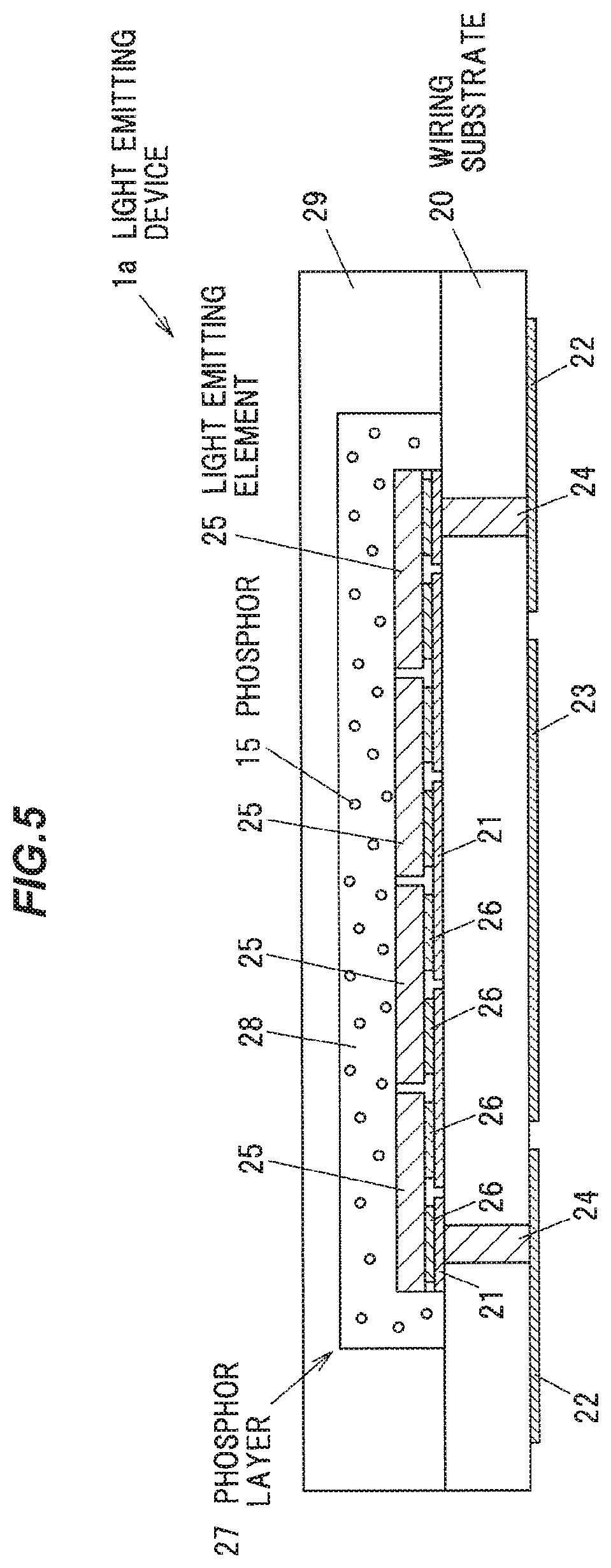
FIG. 5 is a vertical cross sectional view showing a FC-COB type light emitting device in Example 2;
FIG. 6A shows emission spectra of three kinds of SMD type light emitting devices (Samples 1 to 3) in Example 2;
FIG. 6B shows emission spectra of the three FC-COB type light emitting devices (Samples 4 to 6) in Example 2;
FIG. 7 is a vertical cross sectional view showing a FU-COB type light emitting device in Example 3;
FIG. 8A shows emission spectra of two kinds of SMD type light emitting devices (Samples 7 and 8) in Example 3; and
FIG. 8B shows emission spectra of the three FU-COB type light emitting devices (Samples 9 to 11) in Example 3.
DETAILED DESCRIPTION OF THE PREFERRED EMBODIMENTS
Embodiments
(Structure of a Light Emitting Device)
FIG. 1 is a vertical cross sectional view showing a light emitting device 1 according to the embodiment. The light emitting device 1 is provided with a case 10 having a recessed portion 10a, a lead frame 11 located in the case 10 so as to be exposed at a bottom of the recessed portion 10a, a light emitting element 12 mounted on the lead frame 11, bonding wire 13 electrically connecting the lead frame 11 and an electrode of the light emitting element 12, sealing resin 14 filled in the recessed portion 10a and sealing the light emitting element 12, and a particle phosphor 15 included in the sealing resin 14.
For example, the case 10 comprises heat plasticity resins such as polyphthalamide resin, a Liquid Crystal Polymer (LCP), and Polycyclohexylene Dimethylene Terephalate (PCT), and thermoset resins such as silicone resin, modified silicone resin, epoxy resin, and modified epoxy resin. The case 10 is formed by injection molding or transfer molding. The case 10 may comprise light reflective particle such as titanium dioxide so as to improve optical reflectance.
For example, the whole or surface of the lead frame 11 comprises conductive materials such as Ag, Cu, and Al.
Typically, the light emitting element 12 is a light emitting diode (LED) element or a laser diode element. In the example shown in FIG. 1, the light emitting element 12 is a face-up type element connected to the lead frame 11 by the bonding wire 13. Meanwhile, the light emitting element 12 may be a face-down type element. The light emitting element 12 may be connected to the lead frame using a connecting member such as a conductive bump except the bonding wire.
For example, the sealing resin 14 comprises resin material such as the silicone resin or the epoxy resin.
The phosphor 15 emits fluorescence by the light emitted from the light emitting element 12 as an excitation source. The phosphor 15 is desirably provided with various types of the phosphors so as to improve a color rendering property of the light emitted from the light emitting device 1.
For example, the phosphor 15 comprises Sr.sub.10(PO.sub.4).sub.6Cl.sub.2:Eu.sup.2+ having a peak emission wavelength of 454 nm, Sr.sub.10(PO.sub.4).sub.6Cl.sub.2:Eu.sup.2+ having the peak emission wavelength of 473 nm, Si.sub.6-zAl.sub.zO.sub.zN.sub.8-z:Eu.sup.2+ having the peak emission wavelength of 544 nm, Ca--Si.sub.12-(m+n)Al.sub.m+nO.sub.nN.sub.16-n having the peak emission wavelength of 594 nm, and CaAlSi(O, N).sub.3:Eu.sup.2+ having the peak emission wavelength of 639 nm.
For example, the phosphors contained in the above phosphor 15 may be replaced by Sr.sub.10(PO.sub.4).sub.6Cl.sub.2:Eu.sup.2+ with BaMgAl.sub.10O.sub.17:Eu.sup.2+ or LaAl(Si.sub.6-zAl.sub.3)N.sub.10-zO.sub.z:Ce.sup.3+, Si.sub.6-zAl.sub.zO.sub.zN.sub.8-z:Eu.sup.2+ or Ca--Si.sub.12-(m+n)Al.sub.m+nO.sub.nN.sub.16-n with (Ba, Sr, Ca).sub.2SiO.sub.4:Eu.sup.2+, and CaAlSi(O, N).sub.3:Eu.sup.2+ with (Ca, Sr)AlSiN.sub.3:Eu.sup.2+ respectively.
Combinations of the phosphors contained in the phosphor 15 and deposition ratio of the phosphors are adjusted so as to satisfy the color rendering property of the light emitted from the light emitting device 1 into a base described below.
The phosphor 15 may be spread in the sealing resin 14 or settled in the bottom of the recessed portion 10a of the case 10.
FIG. 2 is a graph showing an example of a spectrum of mixed light of light emitted from the light emitting element 12 and the fluorescence emitted from the phosphor 15.
The peak of the spectrum at 416 nm shown in FIG. 2 is defined by the light emitted from a violet LED as the light emitting element 12. The other peak at a longer wavelength side from the peak of the spectrum at 416 nm is defined by the fluorescence emitted from the four-type phosphors contained in the phosphor 15.
In this case, as shown in FIG. 2, a spectral radiant flux at the peak emission wavelength of the light emitted from the light emitting element 12, a spectral radiant flux at the shortest peak emission wavelength in the fluorescence emitted from the phosphor 15, and a spectral radiant flux at a trough defined between the peak emission wavelength of the light emitted from the light emitting element 12 and the shortest peak emission wavelength in the fluorescence emitted from the phosphor 15 are respectively defined as I1, I2, and I3.
As I1/I3, the ratio of I1 to I3, and I2/I3, the ratio of I2 to I3 are small, the trough defined between the peak emission wavelength of the light emitted from the light emitting element 12 and the shortest peak emission wavelength in the fluorescence emitted from the phosphor 15 becomes shallow in the spectrum of the mixed light of the light emitted from the light emitting element 12 and the fluorescence emitted from the phosphor 15. Thus, the spectrum of the mixed light comes close to the spectrum of the sunlight.
One embodiment of the light emitting device 1 according to the present embodiment is provided with the light emitting element 12 emitting the light having the peak emission wavelength ranging 405 nm to 425 nm, and the phosphor 15 emitting the fluorescence having the peak at the longer wavelength side from the peak emission wavelength of the light emitted from the light emitting element 12. The one embodiment satisfies 1.55.ltoreq.I1/I3.ltoreq.7.00 and 1.20.ltoreq.I2/I3.ltoreq.5.50. In addition, the general color rendering index Ra of the mixed light of the light emitted from the light emitting element 12 and the fluorescence emitted from the phosphor 15 is not less than 96, where a light of color temperature of 5000 to 6500 K is defined as a reference light. The color temperature of 5000 to 6500 K is equivalent to the color temperature of the sunlight from the morning to about three o'clock in the afternoon.
Another embodiment of the light emitting device 1 according to the present embodiment is provided with the light emitting element 12 emitting the light having the peak emission wavelength ranging 410 nm to 425 nm, and the phosphor 15 emitting the fluorescence having the peak at the longer wavelength side from the peak emission wavelength of the light emitted from the light emitting element 12. The general color rendering index Ra of the fluorescence emitted from the phosphor 15 is not more than 95. The general color rendering index Ra of the mixed light of the light emitted from the light emitting element 12 and the fluorescence emitted from the phosphor 15 is higher than the general color rendering index Ra of the fluorescence emitted from the phosphor 15. In addition, the color rendering index Rf of the mixed light is not less than 96. Here, the general color rendering index Ra of the fluorescence emitted from the phosphor and the general color rendering index Ra and color rendering index Rf of the mixed light are indexes obtained when a light of color temperature of 5000 to 6500 K is defined as a reference light.
The other embodiment of the light emitting device 1 according to the present embodiment is provided with the light emitting element 12 emitting the light having the peak emission wavelength ranging 414 nm to 421 nm, and the phosphor 15 emitting the fluorescence having the peak at the longer wavelength side from the peak emission wavelength of the light emitted from the light emitting element 12. The general color rendering index Ra of the mixed light of the light emitted from the light emitting element 12 and the fluorescence emitted from the phosphor 15 is higher than the general color rendering index Ra of the fluorescence emitted from the phosphor 15. In addition, the color rendering index Rf of the mixed light is not less than 97. Here, the general color rendering index Ra of the fluorescence emitted from the phosphor and the general color rendering index Ra and color rendering index Rf of the mixed light are indexes obtained when a light of color temperature of 5000 to 6500 K is defined as a reference light.
The color rendering index Rg of the mixed light of the light emitted from the abovementioned light emitting element 12 and the fluorescence emitted from the phosphor 15 is desirably not less than 98 and not more than 102. A special color rendering index R9 of the mixed light of the light emitted from the abovementioned light emitting element 12 and the fluorescence emitted from the phosphor 15 is desirably not less than 90.
The above color rendering indexes Rf and Rg are defined by the color rendering indexes used in a new light color rendering property evaluation method "TM-30-15" defined by the Illuminating Engineering Society of North America (IES).
The Rf is a parameter showing color fidelity. The Rf can evaluate the color fidelity in higher accuracy than the general color rendering index Ra since the Rf can be obtained by 99 types of color tests. The maximum of the Rf is defined as 100. It means that the color of the test light comes close to the color of the reference light such as the sunlight if the Rf is close to 100.
The Rg is a parameter showing the color brightness that is not evaluated in the known evaluation method. It is assumed that according as the Rg comes close to 100, the color brightness of the test light is close to the color brightness of the reference light such as the sunlight. The Rg may be less than 100 or more than 100.
Meanwhile, the structure of the light emitting device 1 is not limited to the structure shown in FIG. 1 described above as long as the light emitting device 1 is provided with the light emitting element 12 and the phosphor 15.
(Effects of the Embodiments)
According to the above embodiments, the light emitting device can be provided that is excellent in color rendering property so as to emit a light close to the sunlight, wherein the emitted light is high in general color rendering index Ra, special color rendering index R9 and color rendering indexes Rf and Rg etc.
Example 1
Results of a simulation for obtaining the construction of the light emitting device 1 having excellent color rendering property will be described below.
In the simulation, used as the phosphor 15 are Sr.sub.10(PO.sub.4).sub.6Cl.sub.2:Eu.sup.2+ having a peak emission wavelength of 454 nm, Sr.sub.10(PO.sub.4).sub.6Cl.sub.2:Eu.sup.2+ having a peak emission wavelength of 473 nm, Si.sub.6-zAl.sub.zO.sub.zN.sub.8-z:Eu.sup.2+ having a peak emission wavelength of 544 nm, Ca--Si.sub.12-(m+n)Al.sub.m+nO.sub.nN.sub.16-n having a peak emission wavelength of 594 nm, and CaAlSi(O, N).sub.3:Eu.sup.2+ having a peak emission wavelength of 639 nm.
The wavelength of the light emitted from the light emitting element 12, that is, the excitation wavelength of the phosphor 15 is varied from 385 nm to 430 nm. Thereby, the general color rendering index Ra, the special color rendering index R9, and the color rendering indexes Rf and Rg with respect to the excitation wavelengths are calculated from spectra of the mixed light (hereinafter simply called "mixed light" below) of the light emitted from the light emitting element 12 and the fluorescence emitted from the phosphor 15.
FIG. 3A is a graph showing the example of the spectrum of the mixed light having the excitation wavelength of the phosphor 15 of 395 nm. FIG. 3B is a graph showing the example of the spectrum of the mixed light having the excitation wavelength of the phosphor 15 of 416 nm. FIG. 3C is a graph showing the example of the spectrum of the mixed light having the excitation wavelength of the phosphor 15 of 430 nm. FIGS. 3A to 3C show that the trough defined between the peak emission wavelength of the light emitted from the light emitting element 12 and the shortest peak emission wavelength in the fluorescence emitted from the phosphor 15 in the spectrum of the mixed light becomes shallow according as the wavelength of the light emitted from the light emitting element 12 comes close to the wavelength of the fluorescence emitted from the phosphor 15.
The spectral radiant flux ratios I1/I3, I2/I3 in the spectrum of the mixed light, the general color rendering index Ra of the mixed light, the special color rendering index R9 of the mixed light, and the color rendering indexes Rf and Rg of the mixed light calculated from the simulation will be shown in Tables 1 and 2 described below with respect to the excitation wavelengths.
In Tables 1 and 2, "excitation wavelength" means the wavelength of the light emitted from the light emitting element 12. Also, "only phosphor" means that the spectrum of the fluorescence emitted from the phosphor 15 is only applied to the simulation. Further, "CCT" means the Correlated Color Temperature.
TABLE-US-00001 TABLE 1 Excitation Only Wavelength Phosphor 385 nm 395 nm 405 nm 410 nm 411 nm 412 nm 413 nm 414 nm 415 nm CCT 5206K 5218K 5231K 5293K 5359K 5377K 5397K 5419K 5443K 5469K I1/I3 -- 23.57 30.17 6.93 4.69 4.29 3.92 3.59 3.31 3.05 I2/I3 -- 18.44 23.60 5.42 3.67 3.35 3.06 2.81 2.59 2.39 Ra 95 95 95 96 96 96 96 96 97 97 R9 86 86 87 89 91 91 92 92 93 94 Rf 90 91 91 94 96 97 97 97 97 97 Rg 97 97 97 98 99 99 99 100 100 100
TABLE-US-00002 TABLE 2 Excitation Wavelength 416 nm 417 nm 418 nm 419 nm 420 nm 421 nm 422 nm 423 nm 425 nm 430 nm CCT 5497K 5528K 5561K 5596K 5634K 5674K 5716K 5759K 5850K 6082K I1/I3 2.83 2.62 2.44 2.27 2.12 1.98 1.86 1.75 1.57 1.29 I2/I3 2.21 2.05 1.91 1.78 1.66 1.55 1.46 1.37 1.23 1.01 Ra 97 97 97 97 97 97 96 96 96 94 R9 94 95 96 97 97 97 97 96 94 89 Rf 97 97 97 97 97 97 96 96 96 95 Rg 101 101 101 101 102 102 102 102 103 104
FIG. 4A is a graph that plots the general color rendering index Ra shown in Tables 1 and 2. The general color rendering index Ra of the mixed light is not less than 95 within the excitation wavelength range of 385 nm to 425 nm. The general color rendering index Ra of the mixed light is not less than 96 within the excitation wavelength range of 405 nm to 425 nm. The general color rendering index Ra of the mixed light is not less than 97 within the excitation wavelength range of 414 nm to 421 nm.
While the excitation wavelength ranges 405 nm to 425 nm, the general color rendering index Ra of the mixed light is higher than the general color rendering index Ra of the fluorescence emitted from the phosphor 15 since the general color rendering index Ra of only the fluorescence emitted from the phosphor 15 is 95.
FIG. 4B is a graph that plots the special color rendering index R9 in Tables 1 and 2. The special color rendering index R9 of the mixed light is not less than 90 within the excitation wavelength range of 410 nm to 425 nm.
FIG. 4C is a graph that plots color rendering indexes Rf and Rg in Tables 1 and 2. The general color rendering index Rf of the mixed light is not less than 96 within the excitation wavelength range of 410 nm to 425 nm. The general color rendering index Rf of the mixed light is not less than 97 within the excitation wavelength range of 411 nm to 421 nm. Moreover, the general color rendering index Rg of the mixed light ranges 98 to 102 within the excitation wavelength range of 405 nm to 423 nm.
According to Tables 1 and 2, it is found that the general color rendering index Ra of the mixed light is not less than 96 where 1.55.ltoreq.I1/I3.ltoreq.7.00 and 1.20.ltoreq.I2/I3.ltoreq.5.50 are approximately satisfied.
Example 2
Example 2 exemplifying light emitting devices, which emit light excellent in color rendering property, manufactured based on the simulation results of Example 1 will be described below. In Example 2, the light emitting devices of six kinds of phosphors are each manufactured so as to measure emission spectra thereof to obtain the color temperature, the general color rendering index Ra, and the color rendering indexes Rf and Rg.
In Example 2, a surface-mount device type (SMD type) light emitting device 1 constructed as shown in FIG. 1 and a chip-on-board type (FC-COB type) light emitting device 1a with a flip-chip type light emitting element mounted thereon are each manufactured so as to measure the emission spectra thereof.
FIG. 5 is a vertical cross sectional view showing the FC-COB type light emitting device 1a in Example 2. The light emitting device 1a is provided with a wiring substrate 20, plural light emitting elements 25 mounted on the surface of the wiring substrate 20, a phosphor layer 27 covering the surface of the light emitting elements 25, and a sealing member 29 covering the surface of the phosphor layer 27.
A wiring 21 is formed on the upper surface of the wiring substrate 20 and a conduction pattern 22 and a heat-dissipation pattern 23 are formed on the bottom surface of the wiring substrate 20. The wiring 21 and the conduction pattern 22 are electrically connected by a via-hole 24.
The light emitting element 25 has the same emission property as the light emitting element 12 of the light emitting device 1. Electrodes 26 of the light emitting element 25 are connected to the wiring 21 by a conductive paste (not shown).
The phosphor layer 27 is formed on the light emitting elements 25 by coating and is composed of a binder resin 28 and a phosphor 15 included in the binder resin 28.
In Example 2, used as the phosphor 15 included in the light emitting devices 1 and 1a are (Ba, Sr).sub.10(PO.sub.4).sub.6Cl.sub.2:Eu.sup.2+ having a peak emission wavelength of 454 nm and FWHM (full width at half maximum) of 53 nm, (Ba, Sr).sub.10(PO.sub.4).sub.6Cl.sub.2:Eu.sup.2+ having a peak emission wavelength of 473 nm and FWHM of 81 nm, Si.sub.6-zAl.sub.zO.sub.zN.sub.8-z:Eu.sup.2+ having a peak emission wavelength of 544 nm and FWHM of 55 nm, Ca--Si.sub.12-(m+n)Al.sub.m+nO.sub.nN.sub.16-n having a peak emission wavelength of 594 nm and FWHM of 84 nm, CaAlSi(O, N).sub.3:Eu.sup.2+ having a peak emission wavelength of 639 nm FWHM of 125 nm, and CaAlSiN.sub.3:Eu.sup.2+ having a peak emission wavelength of 668 nm FWHM of 93 nm. The sealing resin 14 and the binder resin 28 are of a methyl-based silicone resin.
Table 3 below shows excitation wavelengths (i.e., emission wavelength of the light emitting element 12) of the phosphor 15 of the three kinds of SMD type light emitting devices 1 (Samples 1 to 3), the six kinds of phosphors composing the phosphor 15, and a mixing ratio (mass ratio) of a resin composing the sealing resin 14.
TABLE-US-00003 TABLE 3 Sample 1 2 3 Excitation wavelength (peak value) 418.6 nm 416.6 nm 420.9 (FWHM: 13.8 nm) nm Mixing (Ba,Sr).sub.10(PO.sub.4).sub.6Cl.sub.2:Eu.sup.2+ 13.3 23.7 18.9 ratio (Ba,Sr).sub.10(PO.sub.4).sub.6Cl.sub.2:Eu.sup.2+ 27.1 21.4 28.3 (mass %) Si.sub.6-zAl.sub.zO.sub.zN.sub.8-z:Eu.sup.2+ 1.6 1.3 1.4 Ca--Si.sub.12-(m+n)Al.sub.m+nO.sub.nN.sub.16-n 1.4 1.2 1 CaAlSi(O,N).sub.3:Eu.sup.2+ 1 1.1 1 CaAlSiN.sub.3:Eu.sup.2+ 0.4 0.4 0.4 Methyl-based silicone 55.2 50.9 49
FIG. 6A shows emission spectra of the three kinds of SMD type light emitting devices 1 (Samples 1 to 3) in Example 2.
Table 4 below shows the emission efficiency, correlated color temperature (CCT) of the three SMD type light emitting devices 1 (Samples 1 to 3), and the spectral radiant flux ratios I1/I3 and I2/I3, general color rendering index Ra, and color rendering indexes Rf and Rg obtained from the emission spectra in FIG. 6A.
TABLE-US-00004 TABLE 4 Sample 1 2 3 Emission 112 lm/W 107 lm/W 112 lm/W efficiency CCT 6817 6403 6419 CCT (target 6500 6500 6500 value) I1/I3 1.517 1.503 1.682 I2/I3 1.135 1.295 1.025 Ra 97 99 96 Rf 97 98 96 Rg 100 100 101
Table 5 below shows excitation wavelengths (i.e., emission wavelength of the light emitting element 25) of the phosphor 15 of the three kinds of FC-COB type light emitting devices 1a (Samples 4 to 6), the six phosphors composing the phosphor 15, and a mixing ratio (mass ratio) of a resin composing the binder resin 28. Also, Table 5 shows a simulation-calculated thickness (i.e., a thickness of a part on the light emitting elements 25 of the phosphor layer 27) of the phosphor layer 27.
TABLE-US-00005 TABLE 5 Sample 4 5 6 Excitation wavelength (peak value) 417.5 nm 417.5 nm 417.5 (FWHM: 13.8 nm) nm Mixing (Ba,Sr).sub.10(PO.sub.4).sub.6Cl.sub.2:Eu.sup.2+ 15.37 15.37 15.37 ratio (Ba,Sr).sub.10(PO.sub.4).sub.6Cl.sub.2:Eu.sup.2+ 50.5 50.5 50.5 (mass %) Si.sub.6-zAl.sub.zO.sub.zN.sub.8-z:Eu.sup.2+ 3.59 3.59 3.59 Ca--Si.sub.12-(m+n)Al.sub.m+nO.sub.nN.sub.16-n 1.23 1.23 1.23 CaAlSi(O,N).sub.3:Eu.sup.2+ 5.63 5.63 5.63 CaAlSiN.sub.3:Eu.sup.2+ 0.72 0.72 0.72 Methyl-based silicone 22.96 22.96 22.96 Thickness of phosphor layer 120 110 125
FIG. 6B shows emission spectra of the three FC-COB type light emitting devices 1a (Samples 4 to 6) in Example 2.
Table 6 below shows the correlated color temperature (CCT) of the FC-COB type light emitting devices 1a (Samples 4 to 6), and the spectral radiant flux ratios I1/I3 and I2/I3, general color rendering index Ra, and color rendering indexes Rf and Rg obtained from the emission spectra in FIG. 6B. However, the ratios I1/I3 and I2/I3 of Sample 6 cannot be obtained because the corresponding peaks are difficult to identify.
TABLE-US-00006 TABLE 6 Sample 4 5 6 CCT 5510 6446 5085 CCT (target 5500 6500 5000 value) I1/I3 1.239 1.169 -- I2/I3 1.012 1.037 -- Ra 97 99 96 Rf 97 98 96 Rg 100 100 101
As a result, it is found that the light emitting devices 1 and 1a emitting a light excellent in color rendering property can be obtained by using the six kinds of phosphors where the excitation wavelength of the phosphor is set to be not less than 405 nm and not more than 425 nm.
Although all of Samples 1 to 6 in Example 2 does not satisfy the conditions of 1.55.ltoreq.I1/I3.ltoreq.7.00 and 1.20.ltoreq.I2/I3.ltoreq.5.50 obtained by the simulation results in Example 1, they have high Ra, Rf and Rg values. It is assumed that this is caused by a difference between the target value of CCT and the real values thereof etc. Thus, the results of Example 2 teach that the high Ra, Rf and Rg values can be obtained even if the conditions of 1.55.ltoreq.I1/I3.ltoreq.7.00 and 1.20.ltoreq.I2/I3.ltoreq.5.50 are not satisfied.
Example 3
Example 3 exemplifying light emitting devices, which emit light excellent in color rendering property, manufactured based on the simulation results of Example 1 will be described below. In Example 3, the light emitting devices of four kinds of phosphors are each manufactured so as to measure emission spectra thereof to obtain the color temperature, the general color rendering index Ra, and the color rendering indexes Rf and Rg.
In Example 3, a surface-mount device type (SMD type) light emitting device 1 constructed as shown in FIG. 1 and a face-up chip-on-board type (FU-COB type) light emitting device 1b with a face-up type light emitting element mounted thereon are each manufactured so as to measure the emission spectra thereof.
FIG. 7 is a vertical cross sectional view showing the FU-COB type light emitting device 1b in Example 3. The light emitting device 1b is provided with a substrate 30, plural light emitting elements 32 mounted on the surface of the substrate 30 and electrically connected to electrodes 31 by bonding wires 33, a ring-shaped dam formed surrounding the mount region of the plural light emitting elements 32, a sealing resin 35 sealing the plural light emitting elements 32, and particulate phosphors 15 included in the sealing resin 35.
In Example 3, used as the phosphor 15 included in the light emitting devices 1 and 1b are (Ba, Sr).sub.10(PO.sub.4).sub.6Cl.sub.2:Eu.sup.2+ having a peak emission wavelength of 455 nm and FWHM (full width at half maximum) of 59 nm, (Ba, Sr).sub.10(PO.sub.4).sub.6Cl.sub.2:Eu.sup.2+ having a peak emission wavelength of 482 nm and FWHM of 83 nm, (Ba, Sr).sub.2SiO.sub.4:Eu.sup.2+ having a peak emission wavelength of 549 nm and FWHM of 87 nm, and CaAlSi(O, N).sub.3:Eu.sup.2+ having a peak emission wavelength of 644 nm FWHM of 122 nm. The sealing resins 14 and 35 are of a methyl-based silicone resin.
Table 7 below shows excitation wavelengths (i.e., emission wavelength of the light emitting element 12) of the phosphor 15 of the two kinds of SMD type light emitting devices 1 (Samples 7 and 8), the four kinds of phosphors composing the phosphor 15, and a mixing ratio (mass ratio) of a resin composing the sealing resin 14.
TABLE-US-00007 TABLE 7 Sample 7 8 Excitation wavelength (peak value) 416.5 nm 416.5 nm (FWHM: 13.8 nm) Mixing (Ba,Sr).sub.10(PO.sub.4).sub.6Cl.sub.2:Eu.sup.2+ 23.33 27.79 ratio (Ba,Sr).sub.10(PO.sub.4).sub.6Cl.sub.2:Eu.sup.2+ 11.07 14.96 (mass %) (Ba,Sr).sub.2SiO.sub.4:Eu.sup.2+ 2.8 2.5 CaAlSi(O,N).sub.3:Eu.sup.2+ 4.19 4.75 Methyl-based silicone 58.61 50
FIG. 8A shows emission spectra of the two kinds of SMD type light emitting devices 1 (Samples 7 and 8) in Example 3.
Table 8 below shows the emission efficiency, correlated color temperature (CCT) of the two SMD type light emitting devices 1 (Samples 7 and 8), and the spectral radiant flux ratios I1/I3 and I2/I3, general color rendering index Ra, and color rendering indexes Rf and Rg obtained from the emission spectra in FIG. 8A.
TABLE-US-00008 TABLE 8 Sample 7 8 CCT 6484 5025 CCT (target 6500 5000 value) I1/I3 1.625 1.136 I2/I3 1.210 1.421 Ra 97 96 Rf 97 95 Rg 101 100
Table 9 below shows excitation wavelengths (i.e., emission wavelength of the light emitting element 32) of the phosphor 15 of the three kinds of FU-COB type light emitting devices 1b (Samples 9 to 11), the four phosphors composing the phosphor 15, and a mixing ratio (mass ratio) of a resin composing the sealing resin 35.
TABLE-US-00009 TABLE 9 Sample 9 10 11 Excitation wavelength (peak value) 417.5 nm 417.5 nm 417.5 nm (FWHM: 13.8 nm) Mixing (Ba,Sr).sub.10(PO.sub.4).sub.6Cl.sub.2:Eu.sup.2+ 8.99 11.02 22.24 ratio (Ba,Sr).sub.10(PO.sub.4).sub.6Cl.sub.2:Eu.sup.2+ 17.98 22.04 12 (mass %) (Ba,Sr).sub.2SiO.sub.4:Eu.sup.2+ 1.4 1.33 2 CaAlSi(O,N).sub.3:Eu.sup.2+ 2.64 3.61 3.76 Methyl-based silicone 69 62 60
FIG. 8B shows emission spectra of the three FU-COB type light emitting devices 1b (Samples 9 to 11) in Example 3.
Table 10 below shows the correlated color temperature (CCT) of the FU-COB type light emitting devices 1b (Samples 9 to 11), and the spectral radiant flux ratios I1/I3 and I2/I3, general color rendering index Ra, and color rendering indexes Rf and Rg obtained from the emission spectra in FIG. 8B.
TABLE-US-00010 TABLE 10 Sample 9 10 11 CCT 6735 4951 5206 CCT (target 6500 5000 5000 value) I1/I3 1.345 1.204 1.081 I2/I3 1.137 1.283 1.539 Ra 96 95 96 Rf 96 96 97 Rg 102 102 102
As a result, it is found that the light emitting devices 1 and 1b emitting a light excellent in color rendering property can be obtained by using the four kinds of phosphors where the excitation wavelength of the phosphor is set to be not less than 405 nm and not more than 425 nm.
Although all of Samples 8 to 11 in Example 3 does not satisfy the conditions of 1.55.ltoreq.I1/I3.ltoreq.7.00 and 1.20.ltoreq.I2/I3.ltoreq.5.50 obtained by the simulation results in Example 1, they have high Ra, Rf and Rg values. Thus, the results of Example 3 also teach that the high Ra, Rf and Rg values can be obtained even if the conditions of 1.55.ltoreq.I1/I3.ltoreq.7.00 and 1.20.ltoreq.I2/I3.ltoreq.5.50 are not satisfied.
Although the embodiments have been described, the invention is not intended to be limited to the embodiments. The various kinds of modifications can be implemented without departing from the gist of the invention.
Also, the claimed invention is not intended to be limited to the embodiments. Further, it should be noted that all combinations of the features described in the embodiments and the examples are not necessary to solve the problems of the invention.
* * * * *
References
D00000
D00001
D00002
D00003
D00004
D00005
D00006
D00007
D00008
XML
uspto.report is an independent third-party trademark research tool that is not affiliated, endorsed, or sponsored by the United States Patent and Trademark Office (USPTO) or any other governmental organization. The information provided by uspto.report is based on publicly available data at the time of writing and is intended for informational purposes only.
While we strive to provide accurate and up-to-date information, we do not guarantee the accuracy, completeness, reliability, or suitability of the information displayed on this site. The use of this site is at your own risk. Any reliance you place on such information is therefore strictly at your own risk.
All official trademark data, including owner information, should be verified by visiting the official USPTO website at www.uspto.gov. This site is not intended to replace professional legal advice and should not be used as a substitute for consulting with a legal professional who is knowledgeable about trademark law.