Method and apparatus for illuminating the status of a consumable
Honkawa , et al. April 13, 2
U.S. patent number 10,974,943 [Application Number 15/791,156] was granted by the patent office on 2021-04-13 for method and apparatus for illuminating the status of a consumable. This patent grant is currently assigned to Fiji Water Company, LLC. The grantee listed for this patent is FIJI WATER COMPANY, LLC. Invention is credited to Clarence Chia, Bryan Honkawa.


View All Diagrams
| United States Patent | 10,974,943 |
| Honkawa , et al. | April 13, 2021 |
Method and apparatus for illuminating the status of a consumable
Abstract
An apparatus for communicating the status of a consumable includes a sleeve with a tubular housing. The tubular housing has a lumen with a proximal section and a distal section separated by an internal flange. The sleeve includes a battery case or power module with a coaster coupled on the proximal side of the internal flange, an electronic module and a power supply module coupled to the distal side of the internal flange. A sensor in the form of a spring-loaded switch is located on the coaster to trigger and enable a status indicator based on a predetermined weight of a beverage container. The status indicator is an LED light source or wireless signal coupled to the sensor through the electronic module.
| Inventors: | Honkawa; Bryan (Malibu, CA), Chia; Clarence (Redondo Beach, CA) | ||||||||||
|---|---|---|---|---|---|---|---|---|---|---|---|
| Applicant: |
|
||||||||||
| Assignee: | Fiji Water Company, LLC (Los
Angeles, CA) |
||||||||||
| Family ID: | 1000005483856 | ||||||||||
| Appl. No.: | 15/791,156 | ||||||||||
| Filed: | October 23, 2017 |
Prior Publication Data
| Document Identifier | Publication Date | |
|---|---|---|
| US 20180134539 A1 | May 17, 2018 | |
Related U.S. Patent Documents
| Application Number | Filing Date | Patent Number | Issue Date | ||
|---|---|---|---|---|---|
| 62420882 | Nov 11, 2016 | ||||
| Current U.S. Class: | 1/1 |
| Current CPC Class: | B67D 1/0888 (20130101); A47G 23/0309 (20130101); G08B 7/068 (20130101); B67D 1/0004 (20130101) |
| Current International Class: | B67D 1/00 (20060101); A47G 23/03 (20060101); B67D 1/08 (20060101); G08B 7/06 (20060101) |
References Cited [Referenced By]
U.S. Patent Documents
| 1013582 | January 1912 | Bedini |
| 1389132 | August 1921 | Galavan |
| 1714333 | May 1929 | Voss Karl |
| 2439696 | April 1948 | Schaal |
| 2663866 | December 1953 | Simpson |
| 2674675 | April 1954 | Lambert |
| 2745947 | May 1956 | Sansous |
| 3434134 | March 1969 | Batchelor |
| 3810164 | May 1974 | Lambert |
| 3990166 | November 1976 | Nagelkirk |
| 4021795 | May 1977 | Hollingsworth |
| 4344113 | August 1982 | Ditto |
| 4858084 | August 1989 | Sheryll |
| 4922355 | May 1990 | Dietz |
| 4926786 | May 1990 | White |
| 4930902 | June 1990 | Yata |
| 5010461 | April 1991 | Saotome |
| 5083391 | January 1992 | Kyler |
| 5307250 | April 1994 | Pearson |
| 5495081 | February 1996 | Ipcinski |
| 5553735 | September 1996 | Kimura |
| 5594409 | January 1997 | Shank |
| 5704162 | January 1998 | Holtkamp, Jr. |
| 5785407 | July 1998 | Ratcliffe |
| 5839458 | November 1998 | Delcarson |
| 5990790 | November 1999 | Lusareta |
| 6065848 | May 2000 | Tucker |
| 6164796 | December 2000 | La Chiusa |
| 6254247 | July 2001 | Carson |
| 6305817 | October 2001 | Johnston |
| 6354711 | March 2002 | McCoy |
| 6359559 | March 2002 | Rudell |
| 6366196 | April 2002 | Green |
| 6379018 | April 2002 | Rycroft |
| 6419384 | July 2002 | Lewis |
| 6786614 | September 2004 | Ciarrocchi, Jr. |
| 6793363 | September 2004 | Jensen |
| 6863415 | March 2005 | Lu |
| 7018062 | March 2006 | Taylor |
| 7369039 | May 2008 | Knutson |
| 7419072 | September 2008 | Vanella |
| 7501933 | March 2009 | Rousso |
| 7690533 | April 2010 | Stilley |
| 7817058 | October 2010 | Waterhouse |
| D630124 | January 2011 | Connell |
| 7926966 | April 2011 | Winters |
| 8072316 | December 2011 | Mannke, Jr. |
| 8152321 | April 2012 | Lindholm |
| RE43771 | October 2012 | Koncelik, Jr. |
| 8493217 | July 2013 | Biessman |
| 8548856 | October 2013 | Maruszak |
| 8827496 | September 2014 | Vanderschuit |
| 8919981 | December 2014 | Wang |
| 9432758 | August 2016 | Kirk |
| 9545166 | January 2017 | Wells |
| 9764842 | September 2017 | Woicekowski |
| 9839310 | December 2017 | Mongeli |
| 10638864 | May 2020 | Abukar |
| 2004/0017678 | January 2004 | Liu |
| 2004/0114352 | June 2004 | Jensen |
| 2004/0125594 | July 2004 | Wu |
| 2004/0212987 | October 2004 | Lu |
| 2004/0246705 | December 2004 | Lu |
| 2006/0109644 | May 2006 | Saucier, Sr. |
| 2010/0147844 | June 2010 | Connell |
| 2014/0300273 | October 2014 | LeBrun |
Assistant Examiner: Courson; Tania
Attorney, Agent or Firm: Cotman IP Law Group
Parent Case Text
CROSS-REFERENCE TO RELATED APPLICATIONS
The present application is claims the benefit of U.S. Provisional Application Ser. No. 62/420,882, filed on Nov. 11, 2016, specification of which is herein incorporated by reference for completeness of disclosure.
Claims
What is claimed is:
1. An apparatus for communicating the status of a consumable comprising: a tubular housing with a lumen cavity, wherein the lumen cavity comprises a proximal section and a distal section separated by an internal flange; a power module assembly comprising: a coaster coupled on the proximal section of the tubular housing, a top cover, and a bottom cover coupled to the distal section of the tubular housing; a sensor coupled to the coaster for determining a level of beverage in a beverage container; and electronic circuitry for controlling a status indicator, wherein the sensor is in electrical communication with the electronic circuitry; wherein the status indicator is operably coupled to the sensor.
2. The apparatus of claim 1, wherein the sensor is a spring-loaded switch on the coaster that is configured to trigger and enable the status indicator based on a predetermined weight of the beverage container.
3. The apparatus of claim 1, wherein the status indicator is light emitting diode light source on the coaster.
4. The apparatus of claim 1, wherein the electronic circuitry is housed in a chamber that is coupled to the bottom cover.
5. The apparatus of claim 1, wherein the bottom cover comprises one or more batteries.
Description
BACKGROUND OF THE INVENTION
Field of the Invention
Embodiments of the invention relates to visual feedback systems. More specifically, the invention relates to a method and apparatus for communicating the status of a consumable.
Description of the Related Art
Currently, when a restaurant patron orders a bottled water, a glass of water, or any other beverage, a waiter brings the beverage and places it on the table. The patron consumes the beverage and sometimes would have to wait for a long time before a refill. This is primarily because the most prominent way to know that the patron needs a refill is either by the waiter coming to the table and observing that the beverage container is empty or by the patron summoning the waiter and alerting him about needing a refill.
The perceived lack of responsiveness to the patron's needs sometimes lead to frustration and dissatisfaction with a particular establishment.
There are currently no known systems in restaurants of similar environments that provide automatic feedback to waiters of when a patron needs a refill of a beverage, e.g. water.
To overcome the problems and limitations described above there is a need for a method and apparatus for illuminating the status of a consumable.
BRIEF SUMMARY OF THE INVENTION
One or more embodiments of the invention are directed a method and apparatus for communicating the status of a consumable. The invention is a sleeve for providing a visual indication of the status of beverage in a bottle. For instance, in a restaurant environment with one or more sleeves on each table for bottled water, when a customer requests service of water, a bottle is placed in the sleeve on the table thereby enabling the status indicator. In the exemplary embodiment, the status indicator is a light source comprising one or more light emitting diodes (LED). Enabling the light serves multiple purposes, e.g. providing some lighting to the table and also indicating the status of the water in the bottle. Thus, a waiter that passes by the table can easily ascertain whether or not the customer needs a replacement bottle by the status of the light. The sleeve can be configured for use with a can, cup, etc.
In one or more embodiments, the sleeve comprises a tubular housing with a lumen. The lumen is divided into a proximal or top section and a distal or bottom section. The bottom and top sections are separated by an internal flange.
In one or more embodiments, the sleeve further comprises a power module coupled in the lumen of the tubular housing. The power module comprises a coaster coupled on the proximal side of the internal flange, an electronic module and a power supply module coupled to the distal side of the internal flange. The electronic module is housed in a chamber above the power supply module
The sleeve further comprises a sensor coupled to the electronic module for determining the level of beverage in a beverage container. In one or more embodiments, the sensor is a spring-loaded switch on the coaster that is configured to trigger and enable the status indicator based on a predetermined weight of the beverage container.
The sleeve further comprises a status indicator coupled to the sensor. In one or more embodiments, the status indicator is one or more LED light source on the coaster.
In other embodiments of the present invention, the apparatus comprises a coaster for a beverage container. A power module with an electronic module and a power supply module that is coupled to the coaster. A sensor is coupled to the coaster for determining the status of beverage in a beverage container. The sensor is in electrical communication with the electronic module. The apparatus further includes a status indicator coupled to the sensor.
BRIEF DESCRIPTION OF THE DRAWINGS
The above and other aspects, features and advantages of the invention will be more apparent from the following more particular description thereof, presented in conjunction with the following drawings wherein:
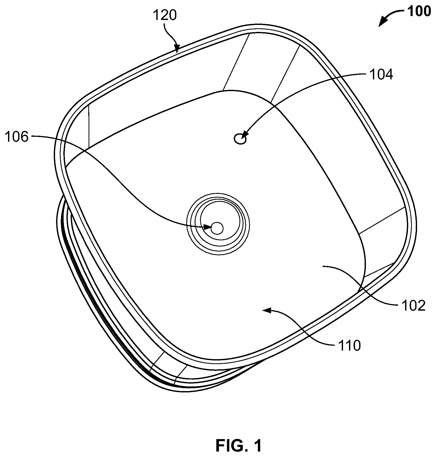
FIG. 1 is a top perspective view of a sleeve for holding a bottle in accordance with one or more embodiments of the present invention.
FIG. 2A is an isometric view of the power module of the sleeve in accordance with one or more embodiments of the present invention.
FIG. 2B is side elevational view of the power module of the sleeve in accordance with one or more embodiments of the present invention.
FIG. 2C is bottom plan view of the power module of the sleeve in accordance with one or more embodiments of the present invention.
FIG. 3 is an exploded view of the sleeve in accordance with one or more embodiments of the present invention.
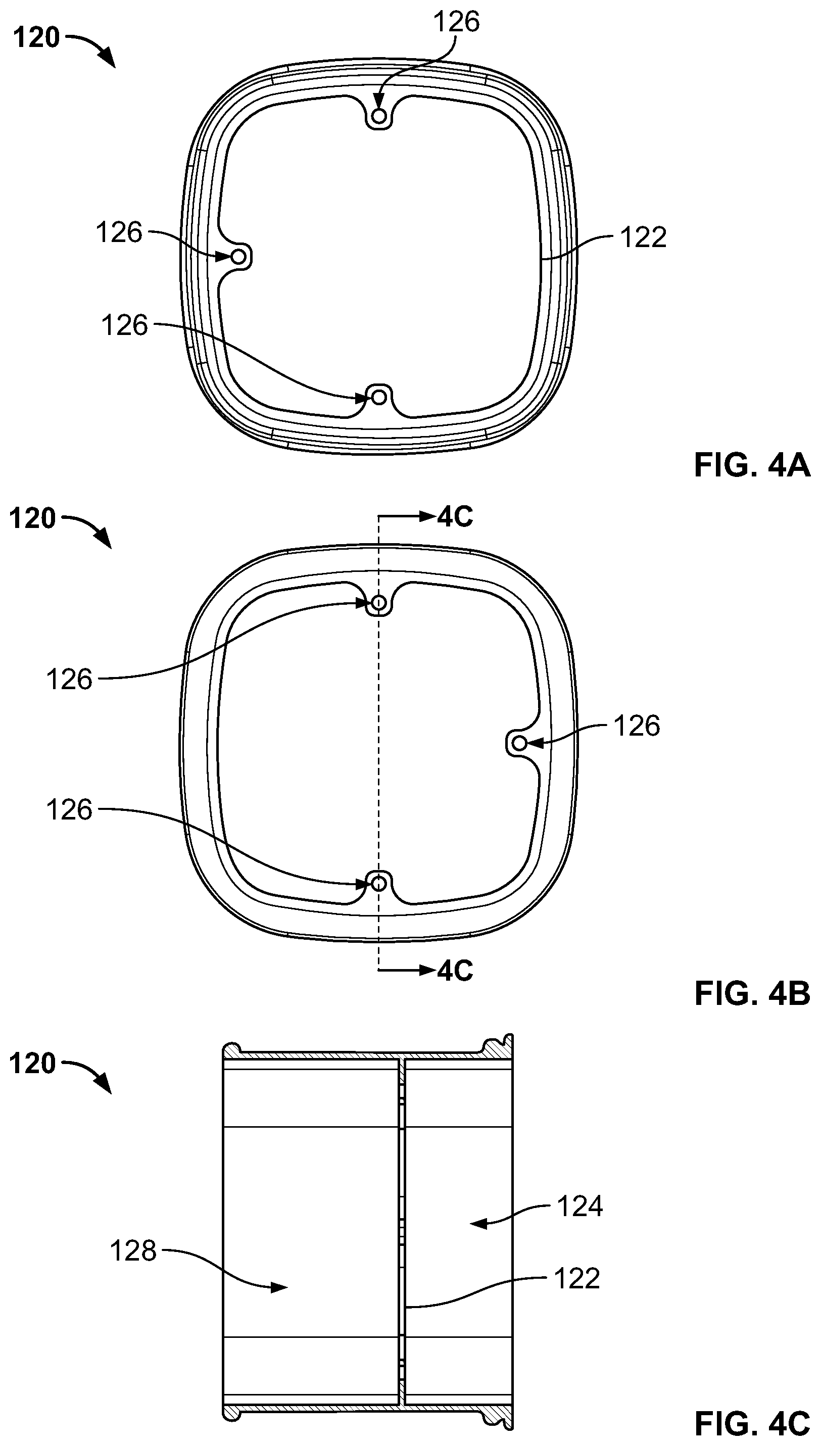
FIG. 4A is top plan view of the housing of the sleeve in accordance with one or more embodiments of the present invention.
FIG. 4B is bottom plan view of the housing of the sleeve in accordance with one or more embodiments of the present invention.
FIG. 4C is cross-sectional view of section A-A of the housing of the sleeve in accordance with one or more embodiments of the present invention.
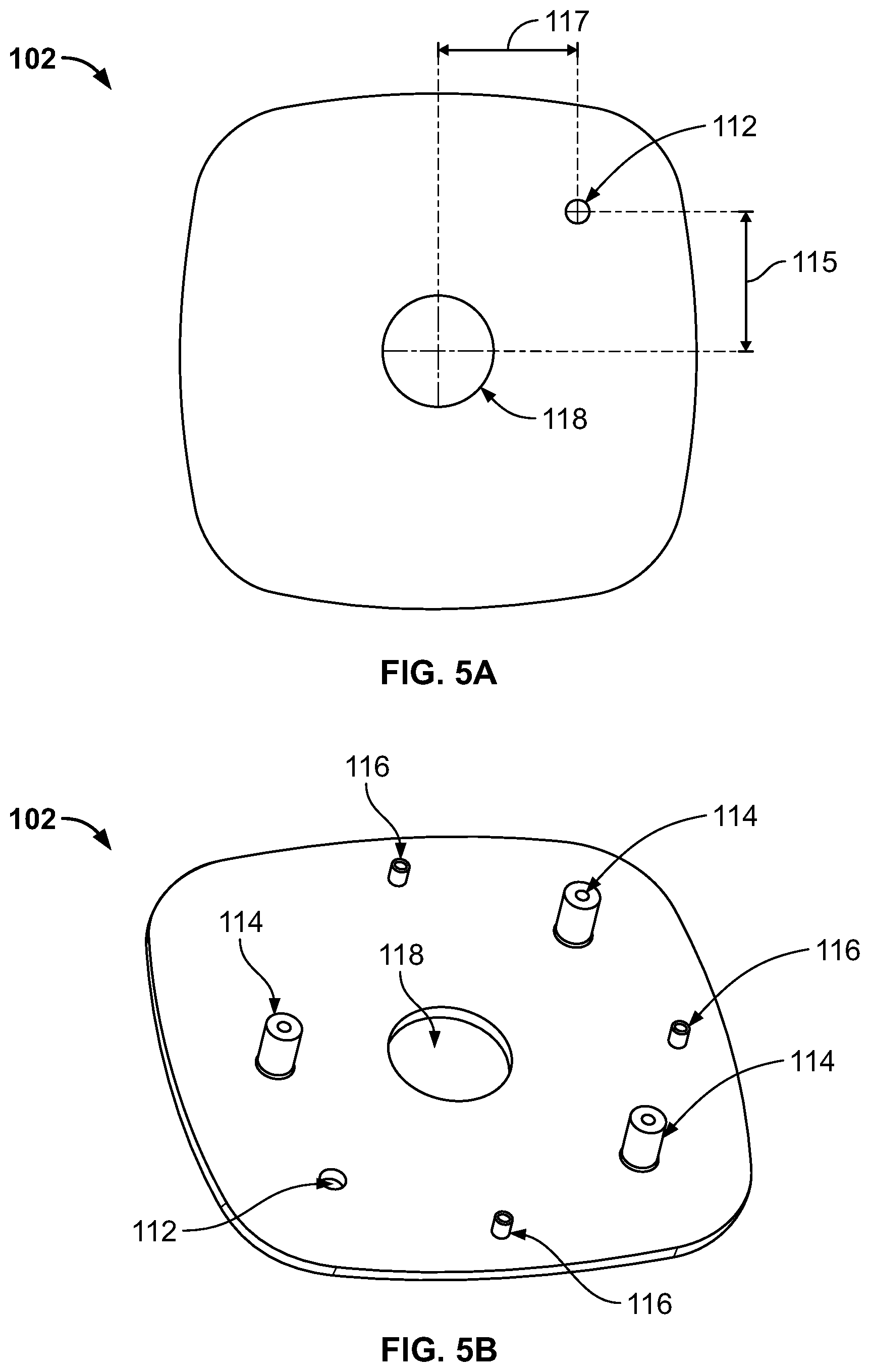
FIG. 5A is top plan view of beverage coaster of the power module in accordance with one or more embodiments of the present invention.
FIG. 5B is bottom perspective view of beverage coaster of the power module in accordance with one or more embodiments of the present invention.
FIG. 6A is top isometric view of the top cover of the power module in accordance with one or more embodiments of the present invention.
FIG. 6B is bottom isometric view of the top cover of the power module in accordance with one or more embodiments of the present invention.
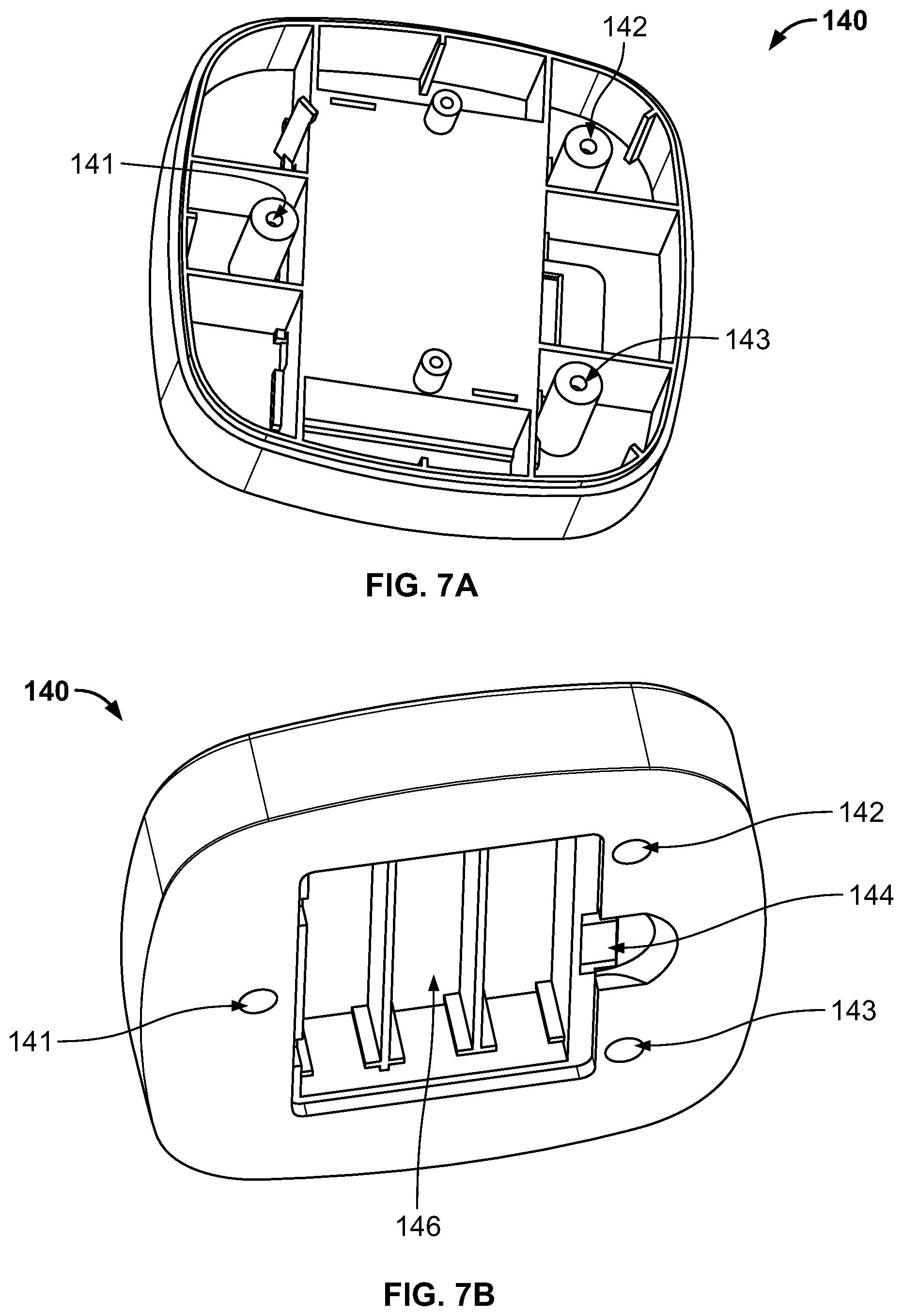
FIG. 7A is top isometric view of the bottom cover of the power module in accordance with one or more embodiments of the present invention.
FIG. 7B is bottom isometric view of the bottom cover of the power module in accordance with one or more embodiments of the present invention.
FIG. 8A is bottom isometric view of the lampshade of the power module in accordance with one or more embodiments of the present invention.
FIG. 8B is top isometric view of the lampshade of the power module in accordance with one or more embodiments of the present invention.
FIG. 9A is bottom isometric view of the battery cover of the battery compartment in accordance with one or more embodiments of the present invention.
FIG. 9B is top isometric view of the battery cover of the battery compartment in accordance with one or more embodiments of the present invention.
FIG. 10 is an illustration showing the sleeve and a corresponding water bottle side by side in accordance with one or more embodiments of the present invention.
FIG. 11 is an illustration showing the water bottle inside the sleeve in accordance with one or more embodiments of the present invention.
DETAILED DESCRIPTION
The present invention comprising a method and apparatus for communicating the status of a consumable will now be described. In the following exemplary description numerous specific details are set forth in order to provide a more thorough understanding of embodiments of the invention. It will be apparent, however, to an artisan of ordinary skill that the present invention may be practiced without incorporating all aspects of the specific details described herein. Furthermore, although steps or processes are set forth in an exemplary order to provide an understanding of one or more systems and methods, the exemplary order is not meant to be limiting. One of ordinary skill in the art would recognize that the steps or processes may be performed in a different order, and that one or more steps or processes may be performed simultaneously or in multiple process flows without departing from the spirit or the scope of the invention. In other instances, specific features, quantities, or measurements well known to those of ordinary skill in the art have not been described in detail so as not to obscure the invention. It should be noted that although examples of the invention are set forth herein, the claims, and the full scope of any equivalents, are what define the metes and bounds of the invention.
For a better understanding of the disclosed embodiment, its operating advantages, and the specified object attained by its uses, reference should be made to the accompanying drawings and descriptive matter in which there are illustrated exemplary disclosed embodiments. The disclosed embodiments are not intended to be limited to the specific forms set forth herein. It is understood that various omissions and substitutions of equivalents are contemplated as circumstances may suggest or render expedient, but these are intended to cover the application or implementation.
The term "first", "second" and the like, herein do not denote any order, quantity or importance, but rather are used to distinguish one element from another, and the terms "a" and "an" herein do not denote a limitation of quantity, but rather denote the presence of at least one of the referenced item.
Spatially relative terms, such as "beneath," "below," "lower," "under," "above," "upper," and the like, may be used herein for ease of explanation to describe one element or feature's relationship to another element(s) or feature(s) as illustrated in the figures. It will be understood that the spatially relative terms are intended to encompass different orientations of the device in use or in operation, in addition to the orientation depicted in the figures. For example, if the device in the figures is turned over, elements described as "below" or "beneath" or "under" other elements or features would then be oriented "above" the other elements or features. Thus, the example terms "below" and "under" can encompass both an orientation of above and below. The device may be otherwise oriented (e.g., rotated 90 degrees or at other orientations) and the spatially relative descriptors used herein should be interpreted accordingly.
It will be understood that when an element or layer is referred to as being "on," "connected to," or "coupled to" another element or layer, it can be directly on, connected to, or coupled to the other element or layer, or one or more intervening elements or layers may be present. In addition, it will also be understood that when an element or layer is referred to as being "between" two elements or layers, it can be the only element or layer between the two elements or layers, or one or more intervening elements or layers may also be present.
As used herein, the term "substantially," "about," and similar terms are used as terms of approximation and not as terms of degree, and are intended to account for the inherent deviations in measured or calculated values that would be recognized by those of ordinary skill in the art. Further, the use of "may" when describing embodiments of the present invention refers to "one or more embodiments of the present invention." As used herein, the terms "use," "using," and "used" may be considered synonymous with the terms "utilize," "utilizing," and "utilized," respectively. Also, the term "exemplary" is intended to refer to an example or illustration.
Unless otherwise defined, all terms (including technical and scientific terms) used herein have the same meaning as commonly understood by one of ordinary skill in the art to which the present invention belongs. It will be further understood that terms, such as those defined in commonly used dictionaries, should be interpreted as having a meaning that is consistent with their meaning in the context of the relevant art and/or the present specification, and should not be interpreted in an idealized or overly formal sense, unless expressly so defined herein. For the purposes of this application, the term lumen may be interchanged with lumen cavity and both lumen and lumen cavity may be defined as the cavity of a tubular part.
One or more embodiments of the present invention will now be described with references to FIGS. 1-11.
FIG. 1 is a top perspective view of sleeve 100 for holding a bottle in accordance with one or more embodiments of the present invention. As illustrated, sleeve 100 comprises body (or housing) 120; power module 110 coupled to and housed inside body 100; a switch 104; and a status indicator 106.
FIGS. 2A-2C are different views of the power module 110 of the sleeve in accordance with one or more embodiments of the present invention. As illustrated, power module 110 comprises beverage coaster 102; electronic module container or top cover 130; bottom cover or power supply module 140; battery compartment cover 150; switch 104; and status indicator 106.
FIG. 3 is an exploded view of the sleeve 100 to show relationship of the components in accordance with one or more embodiments of the present invention. As illustrated, beverage coaster 102 is coupled to the remainder of the power module 110 through inward projecting flange 122 at the proximal end 128 (i.e. top section) of the housing 120 (see FIG. 4). Internal flange 122 includes one or more guiding holes 126 for corresponding guideposts 116 (see FIG. 5B). Each guidepost 116 on the backside of beverage coaster 102 is configured to fit into a corresponding guiding hole 126 on flange 122.
The remaining elements of the power module 110 are coupled to the distal end 124 (i.e. bottom section) of the housing 120. As illustrated in FIG. 3, the relationship of the elements is such that the battery compartment cover 150 is coupled to the bottom side of the bottom cover 140; lampshade 160 is located between bottom cover 140 and top cover 130; and top cover 130 resides on the distal side of flange 122 and inside the housing 120 at section 124.
FIGS. 4A-C are different views of the housing 120 in accordance with one or more embodiments of the present invention. As illustrated, housing 120 is a tubular member with a lumen comprising a top section 128 and a bottom section 124 separated by an inward projecting flange (or shelf) 122. Flange 122 includes one or more guiding holes 126. Preferably, flange 122 includes two or more guiding holes to minimize any rotational movement of the beverage coaster inside the housing. Specifically, in the illustrated embodiment, flange 122 includes three guiding holes on three sides of the substantially four sided housing. Preferably, the internal shape of housing 120 will depend on the shape of beverage bottle 10 (see FIG. 11). For instance, the shape of housing 120 could be cylindrical, square (with or without rounded edges), rectangular (with or without rounded edges), or any other desirable shape that can hold a beverage container. However, those of skill in the art would appreciate that the internal shape of housing 120 does not have to be configured for a specific beverage container and that shapes that can accommodate different type and size containers are contemplated.
FIGS. 5A-B are different views of beverage coaster 102 of the power module in accordance with one or more embodiments of the present invention. As illustrated, beverage coaster 102 includes a hole 112 for switch 104 and hole 118 for status indicator 106. Switch 104 is preferably spring-loaded such that it is enabled upon compression by the weight of an object placed on it. In one or more embodiments, spring-loaded switch 104 and status indicator 106 are coupled to electronic circuitry, e.g. circuit board (not shown), in top cover 130. The function of switch 104 is to activate the status indicator 106 when a beverage bottle of a predetermined threshold weight is placed on the coaster 102. Thus, as the beverage in the bottle 10 is consumed, the weight of the bottle and its content decreases and eventually falls below the predetermined threshold weight thereby disengaging the switch. Those of skill in the art would appreciate that other types of switches are contemplated. For example, a sensor on the sidewalls that senses beverage level in the bottle could be used instead of a spring-loaded switch on the coaster, optical switches, etc.
In one or more embodiments, switch 104 is located such that its X and Y distances from the center of the coaster (i.e. 115 and 117) is such that the switch can be optimally activated by the bottom wall of the beverage bottle 10.
In one or more embodiments, the status indicator 106 is an LED light source which includes lampshade 160. An LED lamp (not shown), which is covered by the lampshade 160, lights up when a beverage bottle 10 with sufficient liquid is placed inside the sleeve, i.e. on top of the coaster 102, to visually indicate that the bottle is not empty. Those of skill in the art would appreciate that the status indicator 106 could also be on the outside of the sleeve. In a preferred embodiment, the LED lamp is off when there is no beverage bottle in the sleeve or when the level of the beverage in the bottle causes the weight of bottle and beverage combination to fall below the predetermined threshold value.
In other embodiments of the invention, status indicator 106 could comprise a wireless radio, e.g. Bluetooth, that transmits the status of each sleeve 100 to a mobile device or similar device, e.g. smartphone, computer, tablet, etc. (i.e. smart device). In such embodiment, the status indicator is a signal configured to be wirelessly communicated to a smart device, for example.
FIGS. 8A-B are different views of the lampshade 160 of the power module in accordance with one or more embodiments of the present invention. As illustrated, the lampshade comprises a top wall 162 with a downward flowing sidewall 163 which terminates into an outward flange 164. When installed in the top cover 130, the flange 164 is on the bottom side of top cover 130 while top wall 162 fits through hole 138 of top cover 130 and is exposed on the topside of top cover 130 and also fits through hole 118 of coaster 102. Hole 138 in top cover 130 and hole 118 in coaster 102 are sized to fit the outside perimeter of the sidewall 163 of the lampshade.
Returning back to FIG. 5B, the bottom side of the coaster 102 comprises one or more guideposts 116. Each of the one or more guideposts 116 sized to fit into a corresponding one of guide hole 126 on flange 122 of housing 120. The bottom side of the coaster 102 further comprises one or more coupling posts 114. Each coupling post 114 includes a threaded hole for securing the top cover 130 and bottom cover 140 to the coaster 102.
FIGS. 6A-B are different views of the top cover (or electronic module) 130 of the power module 110 in accordance with one or more embodiments of the present invention. The top cover 130 is configured to house the electronic components for control of the status indicator 106, e.g. a circuit board. The electronic components may include a microcontroller, for instance. The switch 104 and status indicator 106 are coupled to electronic components housed in the top cover 130. The top cover further includes one or more holes 131-133. Each hole, e.g. 131-133, acts as a pass-through for a bolt for coupling the bottom cover 140 to a corresponding threaded hole in post 114 of coaster 102 thereby coupling together the entire power module assembly 110.
FIGS. 7A-B are different views of the bottom cover (or power supply module) 140 of the power module 110 in accordance with one or more embodiments of the present invention. As illustrated, the bottom cover may be configured to house one or more batteries and/or power regulators (e.g. transformers) for the electronic components in battery compartment 146. Those of skill in the art would appreciate that various types of power sources could be employed. For instance, the power supply could be from one or more batteries, an electrical power outlet, etc. Rechargeable batteries could also be used with an external power connector in the power module 110 for recharging the batteries.
In one or more embodiments, the bottom cover 140 further includes one or more through holes, e.g. 141-143, that run its entire height. Each hole, e.g. 141-143, is configured to accept a bolt for coupling the bottom cover 140 to a corresponding threaded hole in post 114 of coaster 102 thereby holding together the entire power supply assembly 110.
Battery cover 150 secures the one or more batteries in the battery compartment 146. FIGS. 9A-B are different views of the battery compartment cover 150 in accordance with one or more embodiments of the present invention. The battery compartment cover 150 includes one or more flaps, e.g. 154, at one end that fit into the distal end of the battery compartment and a latch 152 at the opposing end that engages with a latch hole 144 at the proximal end of the battery compartment 146.
FIG. 10 is an illustration of the sleeve 100 before a corresponding water bottle 10 is placed inside the sleeve. FIG. 11 is an illustration of the water bottle 10 inside the sleeve 100. One purpose of the invention is to provide a visual indication of the status of the beverage in the bottle. For instance, assuming a restaurant environment with one or more sleeves on each table for bottled water. When the customer requests service of water, a bottle is placed in a sleeve on the table thereby enabling the status indicator 106. In the exemplary embodiment where the status indicator is a light source, enabling the light serves multiple purposes, e.g. providing some lighting to the table and also indicating the status of the water in the bottle. Thus, a waiter that passes by the table can easily ascertain whether or not the customer needs a replacement bottle by the status of the light. Of course, the sleeve is not limited to use with a bottle. For instance, it could be used with cans, drinking glasses, etc.
In one or more embodiments of the present invention, the apparatus comprises a coaster 102 for a beverage container. The coaster may optionally be coupled to a housing such as sleeve 120, or a shell body of any other shape. The coaster 102 may be inside the housing or on top of the housing. A sensor is coupled to the coaster for sensing and providing the status of beverage in a beverage container placed on top of the coaster. A power module is coupled to the housing. In one or more embodiments, the power module comprises an electronic module and a power supply module. The electronic module may include a microcontroller, for example.
In one or more embodiments, the power supply module may comprise one or more batteries. The battery may be rechargeable, for instance.
In one or more embodiments, the sensor is in electrical communication with the electronic module is coupled to a status indicator. The status indicator could be a light or a signal wirelessly communicated to a waiter, for example. The status indicated may be activated when the beverage level or quantity in the beverage container is below a predetermined level, for instance. The sensor may be configured to measure the weight of the beverage and container combination or be configured to read the level of beverage in the container. Those of skill in the art would appreciate that there are various ways of determining whether or not a beverage container is empty.
In other embodiments, the status indicator may be configured in the reverse from that discussed above. For instance, instead indicating when the beverage container is about empty, it could indicate when the beverage container is about full. For instance, a green light may be illuminated when the container is not empty and a red light when the container is about empty. An intermediate color may also be added, e.g. yellow, when the container is approaching empty. In such an embodiments, the color scheme may be managed with a microcontroller controlling one or more light emitting diodes with different color spectrums to provide controllability for the color of emitted light.
While the invention herein disclosed has been described by means of specific embodiments and applications thereof, numerous modifications and variations could be made thereto by those skilled in the art without departing from the scope of the invention set forth in the claims.
* * * * *
D00000
D00001
D00002
D00003
D00004
D00005
D00006
D00007
D00008
D00009
D00010
D00011
XML
uspto.report is an independent third-party trademark research tool that is not affiliated, endorsed, or sponsored by the United States Patent and Trademark Office (USPTO) or any other governmental organization. The information provided by uspto.report is based on publicly available data at the time of writing and is intended for informational purposes only.
While we strive to provide accurate and up-to-date information, we do not guarantee the accuracy, completeness, reliability, or suitability of the information displayed on this site. The use of this site is at your own risk. Any reliance you place on such information is therefore strictly at your own risk.
All official trademark data, including owner information, should be verified by visiting the official USPTO website at www.uspto.gov. This site is not intended to replace professional legal advice and should not be used as a substitute for consulting with a legal professional who is knowledgeable about trademark law.