Lordotic expandable fusion implant
Stein April 13, 2
U.S. patent number 10,973,650 [Application Number 16/068,606] was granted by the patent office on 2021-04-13 for lordotic expandable fusion implant. This patent grant is currently assigned to NuVasive, Inc.. The grantee listed for this patent is NuVasive, Inc.. Invention is credited to Christopher Stein.


View All Diagrams
| United States Patent | 10,973,650 |
| Stein | April 13, 2021 |
Lordotic expandable fusion implant
Abstract
The present disclosure provides an expandable spinal implant comprising a plurality of moveable endplates pivotably connect to a housing.
| Inventors: | Stein; Christopher (San Diego, CA) | ||||||||||
|---|---|---|---|---|---|---|---|---|---|---|---|
| Applicant: |
|
||||||||||
| Assignee: | NuVasive, Inc. (San Diego,
CA) |
||||||||||
| Family ID: | 1000005482689 | ||||||||||
| Appl. No.: | 16/068,606 | ||||||||||
| Filed: | December 30, 2016 | ||||||||||
| PCT Filed: | December 30, 2016 | ||||||||||
| PCT No.: | PCT/US2016/069453 | ||||||||||
| 371(c)(1),(2),(4) Date: | July 06, 2018 | ||||||||||
| PCT Pub. No.: | WO2017/117513 | ||||||||||
| PCT Pub. Date: | July 06, 2017 |
Prior Publication Data
| Document Identifier | Publication Date | |
|---|---|---|
| US 20190183656 A1 | Jun 20, 2019 | |
Related U.S. Patent Documents
| Application Number | Filing Date | Patent Number | Issue Date | ||
|---|---|---|---|---|---|
| 62273441 | Dec 31, 2015 | ||||
| 62273390 | Dec 30, 2015 | ||||
| Current U.S. Class: | 1/1 |
| Current CPC Class: | A61F 2/4611 (20130101); A61F 2/4455 (20130101); A61F 2002/30827 (20130101); A61F 2002/30556 (20130101); A61F 2002/30538 (20130101) |
| Current International Class: | A61F 2/44 (20060101); A61F 2/46 (20060101); A61F 2/30 (20060101) |
References Cited [Referenced By]
U.S. Patent Documents
| 5171278 | December 1992 | Pisharodi |
| 5390683 | February 1995 | Pisharodi |
| 5693100 | December 1997 | Pisharodi |
| 5725588 | March 1998 | Errico et al. |
| 5782832 | July 1998 | Larsen et al. |
| 6126689 | October 2000 | Brett |
| 6174334 | January 2001 | Suddaby |
| 6183517 | February 2001 | Suddaby |
| 6332895 | December 2001 | Suddaby |
| 6340369 | January 2002 | Ferree |
| 6344058 | February 2002 | Ferree |
| 6352557 | March 2002 | Ferree |
| 6368351 | April 2002 | Glenn |
| 6409766 | June 2002 | Brett |
| 6419702 | July 2002 | Ferree |
| 6488710 | December 2002 | Besselink |
| 6491724 | December 2002 | Ferree |
| 6500205 | December 2002 | Michelson |
| 6582451 | June 2003 | Marucci et al. |
| 6648918 | November 2003 | Ferree |
| 6652584 | November 2003 | Michelson |
| 6709458 | March 2004 | Michelson |
| 6716247 | April 2004 | Michelson |
| 6719797 | April 2004 | Ferree |
| 6743255 | June 2004 | Ferree |
| 6793679 | September 2004 | Michelson |
| 6808537 | October 2004 | Michelson |
| 6814756 | November 2004 | Michelson |
| 6962606 | November 2005 | Michelson |
| 6972035 | December 2005 | Michelson |
| 6986772 | January 2006 | Michelson |
| 7008453 | March 2006 | Michelson |
| 7044971 | May 2006 | Suddaby |
| 7070598 | July 2006 | Lim et al. |
| 7083650 | August 2006 | Moskowitz et al. |
| 7087055 | August 2006 | Lim et al. |
| 7118579 | October 2006 | Michelson |
| 7118598 | October 2006 | Michelson |
| 7547325 | June 2009 | Biedermann et al. |
| 7608107 | October 2009 | Michelson |
| 7615052 | November 2009 | Serbousek |
| 7621951 | November 2009 | Glenn et al. |
| 7625377 | December 2009 | Veldhuizen et al. |
| 7655027 | February 2010 | Michelson |
| 7678148 | March 2010 | Peterman |
| 7682400 | March 2010 | Zwirkoski |
| 7763028 | July 2010 | Lim et al. |
| 7763074 | July 2010 | Altarac et al. |
| 7846206 | December 2010 | Oglaza et al. |
| 7892286 | February 2011 | Michelson |
| 7901409 | March 2011 | Canaveral et al. |
| 7922729 | April 2011 | Michelson |
| 8007534 | August 2011 | Michelson |
| 8025665 | September 2011 | Lim et al. |
| 8075621 | December 2011 | Michelson |
| 8097034 | January 2012 | Michelson |
| 8097035 | January 2012 | Glenn et al. |
| 8128662 | March 2012 | Altarac et al. |
| 8152837 | April 2012 | Altarac et al. |
| 8182538 | May 2012 | O'Neil et al. |
| 8251891 | August 2012 | Moskowitz et al. |
| 8268001 | September 2012 | Butler et al. |
| 8303658 | November 2012 | Peterman |
| 8317798 | November 2012 | Lim et al. |
| 8328818 | December 2012 | Seifert et al. |
| 8377071 | February 2013 | Lim et al. |
| 8409282 | April 2013 | Kim |
| 8444692 | May 2013 | Michelson |
| 8496664 | July 2013 | Michelson |
| 8523944 | September 2013 | Jimenez et al. |
| 8540452 | September 2013 | Jimenez et al. |
| 8551173 | October 2013 | Lechmann et al. |
| 8579907 | November 2013 | Lim et al. |
| 8603173 | December 2013 | Biedermann et al. |
| 8628577 | January 2014 | Jimenez |
| 8663329 | March 2014 | Ernst |
| 8685095 | April 2014 | Miller et al. |
| 8690917 | April 2014 | Suh et al. |
| 8734520 | May 2014 | Zwirkoski |
| 8771321 | July 2014 | Michelson |
| 8771358 | July 2014 | Michelson |
| 8795365 | August 2014 | Arcenio et al. |
| 8795374 | August 2014 | Chee |
| 8828085 | September 2014 | Jensen |
| 8845726 | September 2014 | Tebbe et al. |
| 8845730 | September 2014 | de Villiers et al. |
| 8894652 | November 2014 | Seifert et al. |
| 8906100 | December 2014 | Jimenez et al. |
| 8940049 | January 2015 | Jimenez et al. |
| 8986386 | March 2015 | Oglaza et al. |
| 8998992 | April 2015 | Seifert et al. |
| 9005291 | April 2015 | Loebl et al. |
| 9034040 | May 2015 | Seifert et al. |
| 9039742 | May 2015 | Altarac et al. |
| 9119726 | September 2015 | Wei |
| 9125692 | September 2015 | Kim |
| 9138327 | September 2015 | McClellan, III |
| 9155572 | October 2015 | Altarac et al. |
| 9204973 | December 2015 | Aflatoon et al. |
| 9220535 | December 2015 | Robling et al. |
| 9259328 | February 2016 | Pabst et al. |
| 9289308 | March 2016 | Marino et al. |
| 9295562 | March 2016 | Lechmann et al. |
| 9333093 | May 2016 | Aflatoon |
| 9345584 | May 2016 | Michelson |
| 9351846 | May 2016 | De Villiers et al. |
| 9351851 | May 2016 | Huffmaster et al. |
| 9381092 | July 2016 | Jimenez et al. |
| 9393130 | July 2016 | Suddaby et al. |
| 9408707 | August 2016 | Oglaza et al. |
| 9408721 | August 2016 | Eastlack et al. |
| 9414933 | August 2016 | Banouskou |
| 9421111 | August 2016 | Baynham |
| 9433510 | September 2016 | Lechmann et al. |
| 9445856 | September 2016 | Seifert et al. |
| 9445917 | September 2016 | Jimenez et al. |
| 9463099 | October 2016 | Levy et al. |
| 9801734 | October 2017 | Stein |
| 2003/0236520 | December 2003 | Lim et al. |
| 2005/0080422 | April 2005 | Otte et al. |
| 2005/0278036 | December 2005 | Leonard et al. |
| 2006/0004455 | January 2006 | Leonard et al. |
| 2007/0118222 | May 2007 | Lang |
| 2007/0149978 | June 2007 | Shezifi et al. |
| 2007/0282443 | December 2007 | Globerman et al. |
| 2008/0114367 | May 2008 | Meyer |
| 2009/0076607 | March 2009 | Aalsma et al. |
| 2009/0157084 | June 2009 | Aalsma et al. |
| 2009/0281628 | November 2009 | Oglaza et al. |
| 2010/0137862 | June 2010 | Diao et al. |
| 2010/0137987 | June 2010 | Diao et al. |
| 2010/0217335 | August 2010 | Chirico et al. |
| 2011/0029086 | February 2011 | Glazer et al. |
| 2011/0257748 | October 2011 | Liu |
| 2012/0101530 | April 2012 | Robling et al. |
| 2012/0185049 | July 2012 | Varela |
| 2012/0290094 | November 2012 | Lim et al. |
| 2013/0103154 | April 2013 | Trieu et al. |
| 2013/0116791 | May 2013 | Theofilos |
| 2013/0144388 | June 2013 | Emery et al. |
| 2013/0190876 | July 2013 | Drochner et al. |
| 2013/0297029 | November 2013 | Kana et al. |
| 2013/0304213 | November 2013 | Aflatoon et al. |
| 2014/0018922 | January 2014 | Marino et al. |
| 2014/0031940 | January 2014 | Banouskou |
| 2014/0039625 | February 2014 | To et al. |
| 2014/0114420 | April 2014 | Robinson |
| 2014/0135776 | May 2014 | Huffmaster et al. |
| 2014/0148904 | May 2014 | Robinson |
| 2014/0156007 | June 2014 | Pabst et al. |
| 2014/0163682 | June 2014 | Lott et al. |
| 2014/0163683 | June 2014 | Seifert et al. |
| 2014/0180419 | June 2014 | Dmuschewsky |
| 2014/0236296 | August 2014 | Wagner et al. |
| 2014/0243983 | August 2014 | Galea et al. |
| 2014/0277139 | September 2014 | Vrionis et al. |
| 2014/0277471 | September 2014 | Gray et al. |
| 2014/0277492 | September 2014 | Wei |
| 2014/0277498 | September 2014 | Ainsworth et al. |
| 2014/0277499 | September 2014 | Ainsworth et al. |
| 2014/0277508 | September 2014 | Baynham |
| 2014/0277510 | September 2014 | Robinson et al. |
| 2014/0296984 | October 2014 | Etminan |
| 2014/0309741 | October 2014 | Ganter et al. |
| 2014/0343677 | November 2014 | Davis et al. |
| 2014/0343678 | November 2014 | Suddaby et al. |
| 2014/0358246 | December 2014 | Levy et al. |
| 2014/0364951 | December 2014 | De Villiers et al. |
| 2015/0012098 | January 2015 | Eastlack et al. |
| 2015/0112437 | April 2015 | Davis et al. |
| 2015/0182347 | July 2015 | Robinson |
| 2015/0230935 | August 2015 | Aflatoon |
| 2015/0238230 | August 2015 | Suh et al. |
| 2015/0342586 | December 2015 | Lim et al. |
| 2016/0022434 | January 2016 | Robinson |
| 2016/0022438 | January 2016 | Lamborne et al. |
| 2016/0030190 | February 2016 | Robinson |
| 2016/0067056 | March 2016 | Armstrong et al. |
| 2016/0074174 | March 2016 | Halverson et al. |
| 2016/0081724 | March 2016 | Robling et al. |
| 2016/0089247 | March 2016 | Nichols et al. |
| 2016/0242927 | August 2016 | Seifert et al. |
| 2016/0250034 | September 2016 | Loebl et al. |
| 2016/0256148 | September 2016 | Huffmaster et al. |
| 2007202404 | Sep 2016 | AU | |||
| 2011203582 | Sep 2016 | AU | |||
| 101502436 | Sep 2016 | CN | |||
| 104248465 | Sep 2016 | CN | |||
| 105232191 | Sep 2016 | CN | |||
| 202568534 | Sep 2016 | CN | |||
| 203183090 | Sep 2016 | CN | |||
| 204306881 | Sep 2016 | CN | |||
| 204931904 | Sep 2016 | CN | |||
| 20314708 | Nov 2003 | DE | |||
| 10344019 | Sep 2016 | DE | |||
| 2777633 | Nov 2003 | EP | |||
| 2717068 | Nov 2003 | FR | |||
| 2813519 | Nov 2003 | FR | |||
| 3006169 | Nov 2003 | FR | |||
| 2008054710 | Nov 2003 | JP | |||
| 2014073405 | Nov 2003 | JP | |||
| 2016013460 | Nov 2003 | JP | |||
| 100395252 | Nov 2003 | KR | |||
| 20020084349 | Nov 2003 | KR | |||
| 2070006 | Nov 2003 | RU | |||
| WO200103616 | Nov 2003 | WO | |||
| WO2005006944 | Nov 2003 | WO | |||
| WO2006042334 | Nov 2003 | WO | |||
| WO2007038349 | Nov 2003 | WO | |||
| WO2007070024 | Nov 2003 | WO | |||
| WO9214423 | Apr 2008 | WO | |||
| WO9525485 | Apr 2008 | WO | |||
| WO2008044057 | Apr 2008 | WO | |||
| WO2010078468 | Apr 2008 | WO | |||
| WO2012089317 | Apr 2008 | WO | |||
| WO2014091028 | Apr 2008 | WO | |||
| WO2014144696 | Apr 2008 | WO | |||
| WO2014186384 | Apr 2008 | WO | |||
| WO2015063719 | Apr 2008 | WO | |||
| WO2015063721 | Apr 2008 | WO | |||
| WO2015097416 | Apr 2008 | WO | |||
| WO2015198335 | Apr 2008 | WO | |||
| WO2016040125 | Apr 2008 | WO | |||
Other References
|
International Search Report for application serial No. PCT/US2016/069453 dated Jul. 6, 2017. cited by applicant . Written Opinion for application serial No. PCT/US2016/069453 dated Jul. 6, 2017. cited by applicant. |
Primary Examiner: Boles; Sameh R
Attorney, Agent or Firm: NuVasive, Inc.
Parent Case Text
CROSS REFERENCE TO OTHER APPLICATIONS
This application claims priority to, and the benefit of, U.S. Provisional Patent Application No. 62/273,390 filed Dec. 30, 2015 and 62/273,441 filed Dec. 31, 2015.
Claims
I claim:
1. An expandable spinal implant comprising a plurality of moveable endplates pivotably connect to a housing; a central body located within the housing wherein the central body comprises a wedge, wherein the central body is laterally translatable with respect to the housing; wherein the plurality of moveable endplates comprise a ramp opposite the central body's wedge that is configured to engage the wedge; a lead screw engaged with the central body; and a passive locking mechanism, wherein the passive locking mechanism comprises a locking collar on the lead screw, wherein the locking collar comprises one or more engagement tabs, wherein the housing comprises one or more recesses on an interior wall, wherein the one or more recesses are configured to receive the one or more engagement tabs.
2. An expandable spinal implant comprising a plurality of moveable endplates pivotably connect to a housing, a central body, a lead screw engaged with the central body and a passive locking mechanism, wherein the central body comprises a wedge, wherein central body is laterally translatable with respect to the housing; wherein the plurality of moveable endplates comprise a ramp opposite the central body's wedge that is configured to engage the wedge, and wherein the passive locking mechanism comprises a locking collar on the lead screw, wherein the locking collar comprises one or more engagement tabs, wherein the housing comprises one or more recesses on an interior wall, wherein the one or more recesses are configured to receive the one or more engagement tabs.
Description
FIELD OF THE DISCLOSURE AND BACKGROUND
The present disclosure pertains to the field spinal implants. More specifically, the present disclosure relates to an expandable spinal fusion implant for use in spine surgery, an insertion tool for use with the expandable fusion implant and a measurement tool useful during spinal surgery.
The expandable spinal fusion implant may be used in combination with bone graft materials to facilitate fusion across the intervertebral region.
BRIEF DESCRIPTION OF THE DRAWINGS
To further illustrate the advantages and features of the present disclosure, a more particular description of the invention will be rendered by reference to specific embodiments which are illustrated in the drawings. It is appreciated that these drawings are not to be considered limiting in scope. The invention will be described and explained with additional specificity and detail through the use of the accompanying drawings in which:
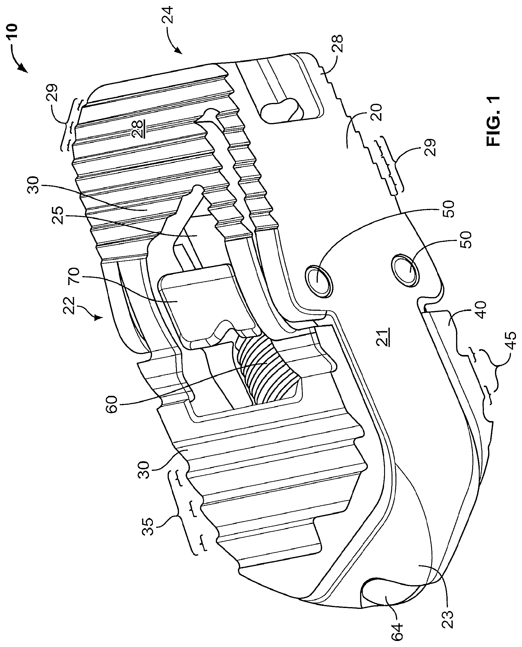
FIG. 1 shows one embodiment of the expandable spinal implant disclosed herein.
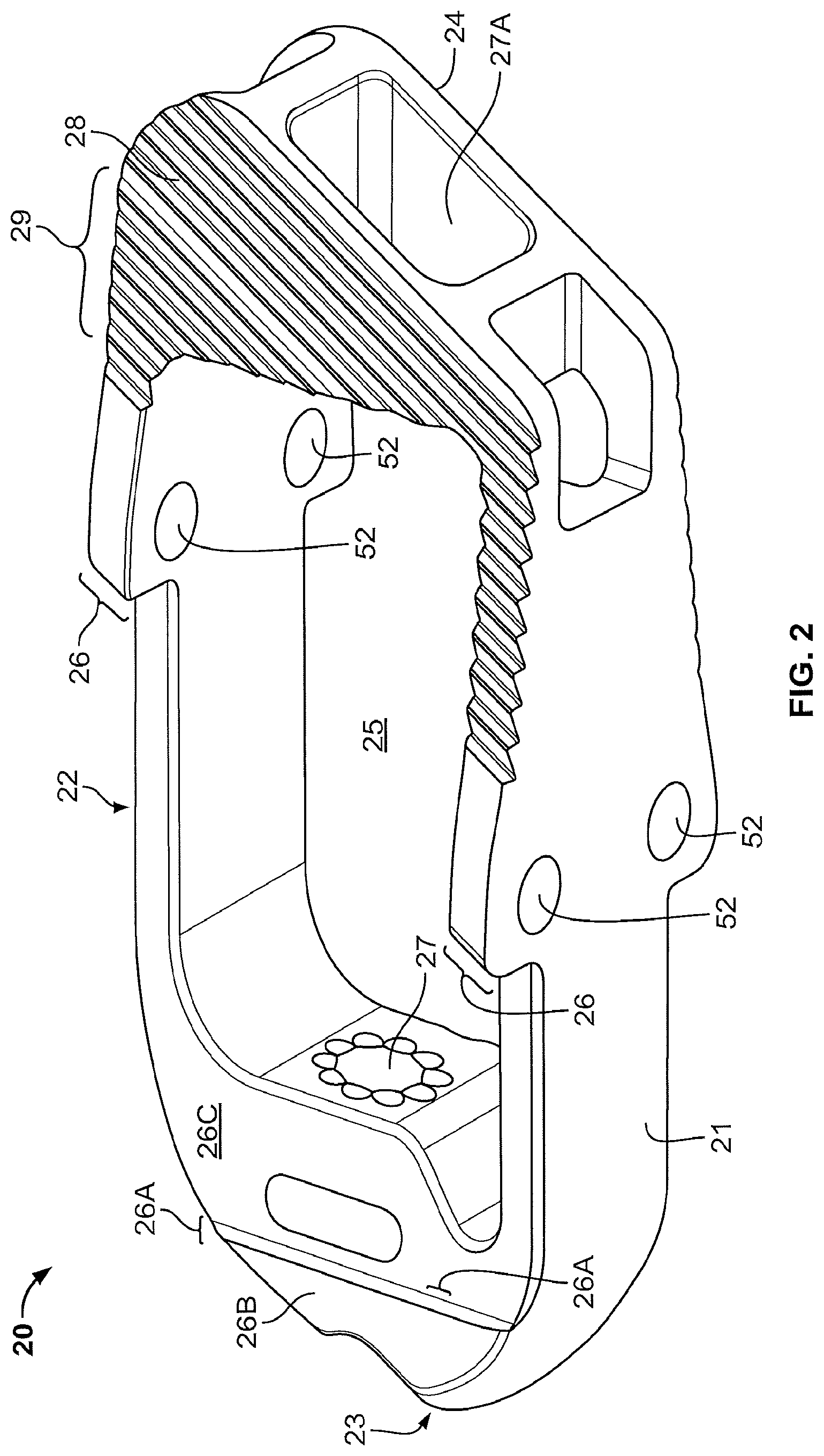
FIG. 2 shows one embodiment of the housing of the expandable spinal implant disclosed herein.
FIG. 3 shows an alternate embodiment of the housing of the expandable spinal implant disclosed herein.
FIG. 4 shows yet another alternate embodiment of the housing of the expandable spinal implant disclosed herein.
FIG. 5 shows a top view of the outer surface of one embodiment of the top moveable endplate of the expandable spinal implant of present disclosure.
FIG. 6 shows a top view of the inner surface of one embodiment of the bottom moveable endplate of the expandable spinal implant of the present disclosure.
FIGS. 7A-7C show a perspective view, top view and side view of one embodiment of the central body of the expandable spinal endplate of the present disclosure.
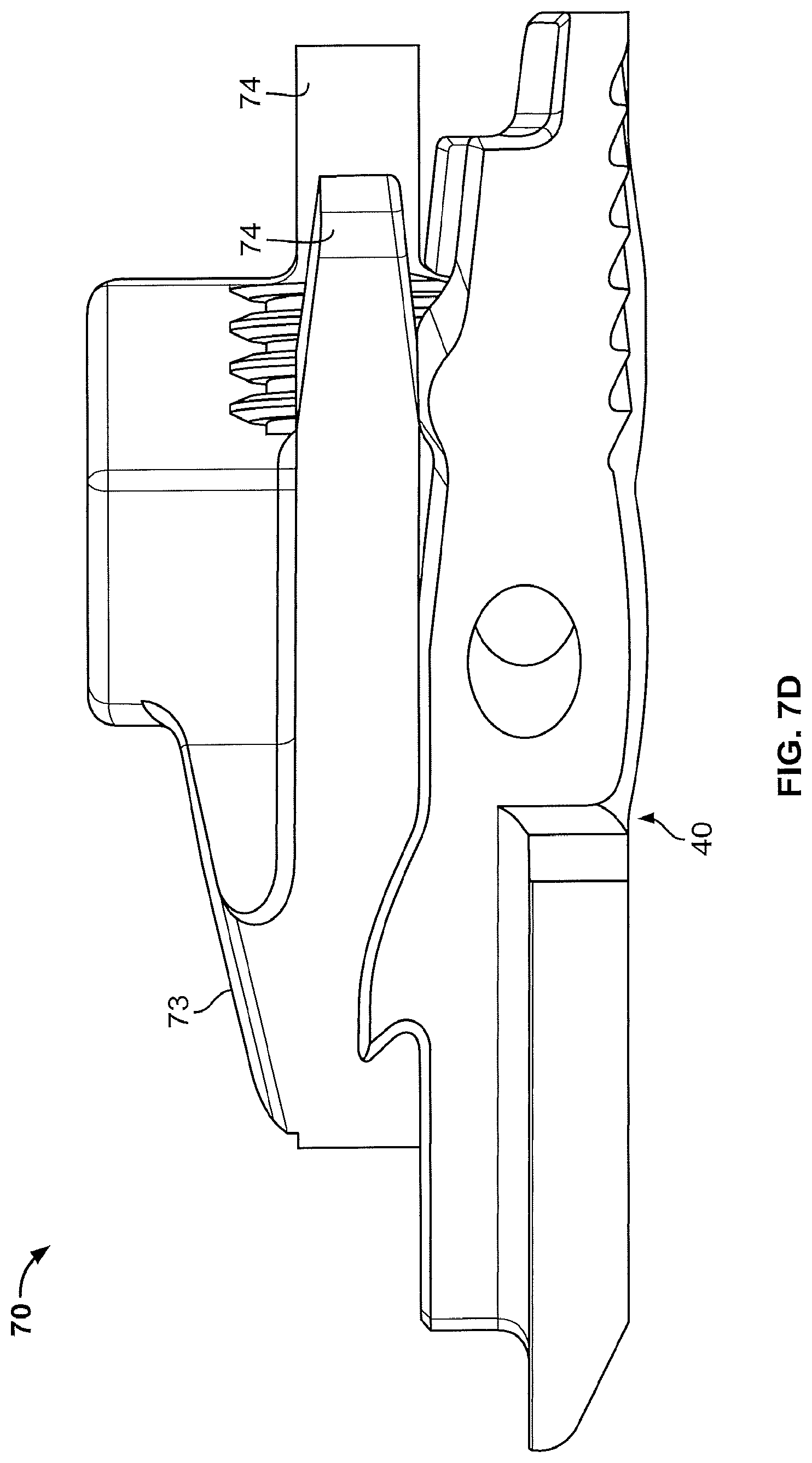
FIG. 7D shows a side view of one embodiment of the central body and lower moveable endplate of the expandable spinal implant of the present disclosure together.
FIG. 8 shows a cross sectional view of one embodiment of the expandable spinal implant of the present disclosure.
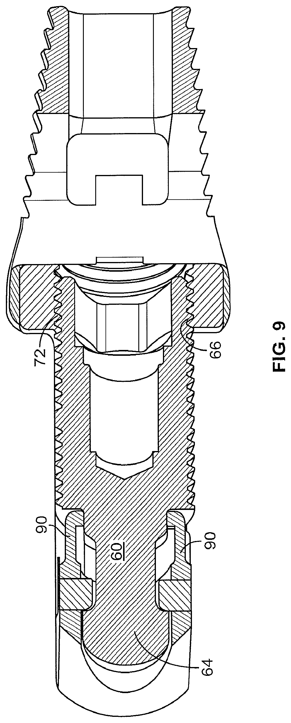
FIG. 9 shows a cross sectional view of an alternate embodiment of the expandable spinal implant of the present disclosure.
FIG. 10 shows a top view of one embodiment of the lead screw, central body and top moveable endplate of the expandable spinal implant of the present disclosure.
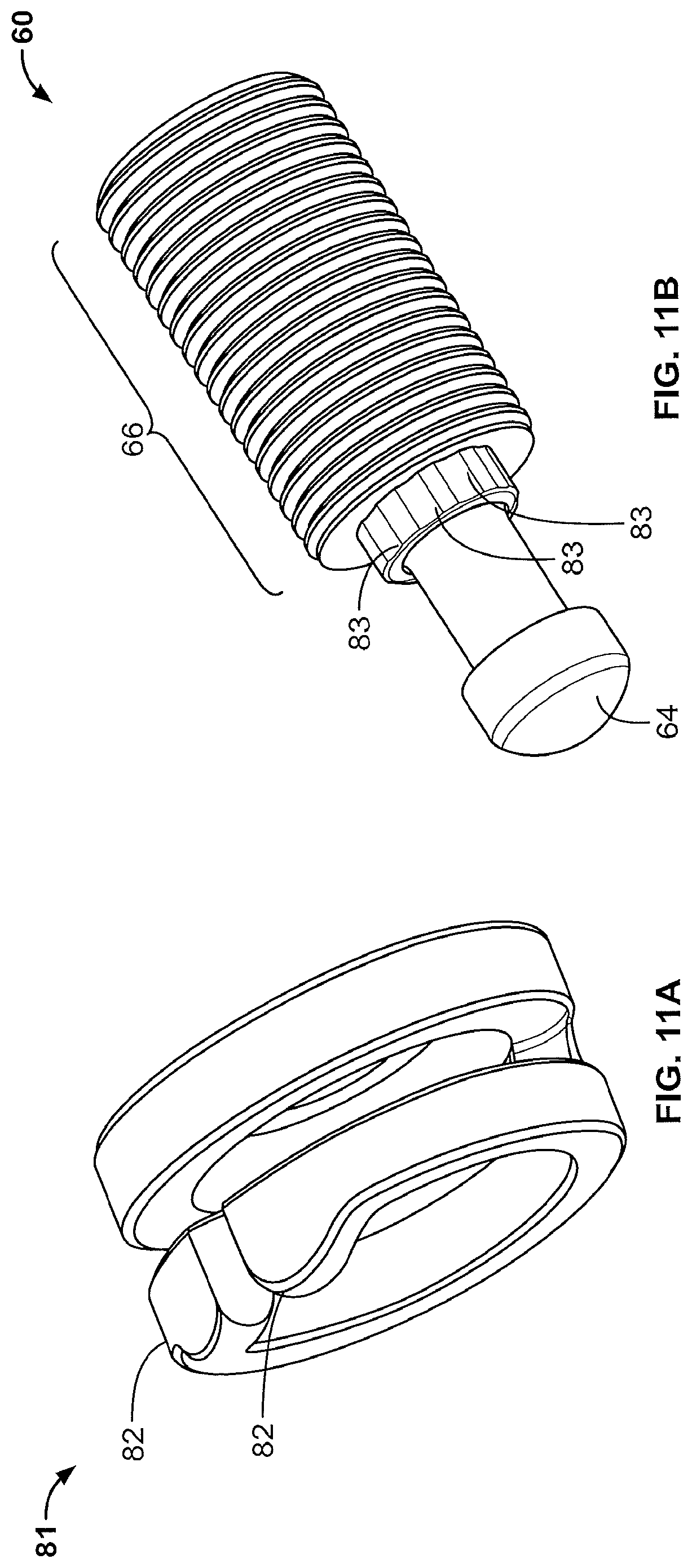
FIG. 11A shows one embodiment of the locking collar of the present disclosure.
FIG. 11B shows one embodiment of the lead screw of the present disclosure.
FIG. 12 shows one embodiment of the locking collar positioned onto a lead screw of the present disclosure.
FIG. 13 shows one embodiment of the lead screw inserted into the housing.
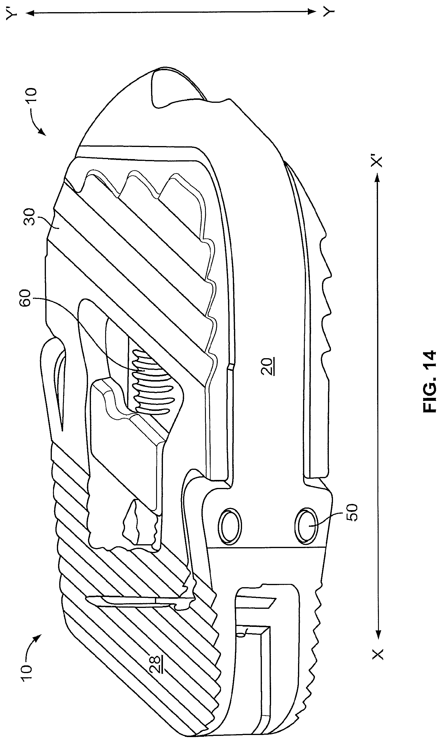
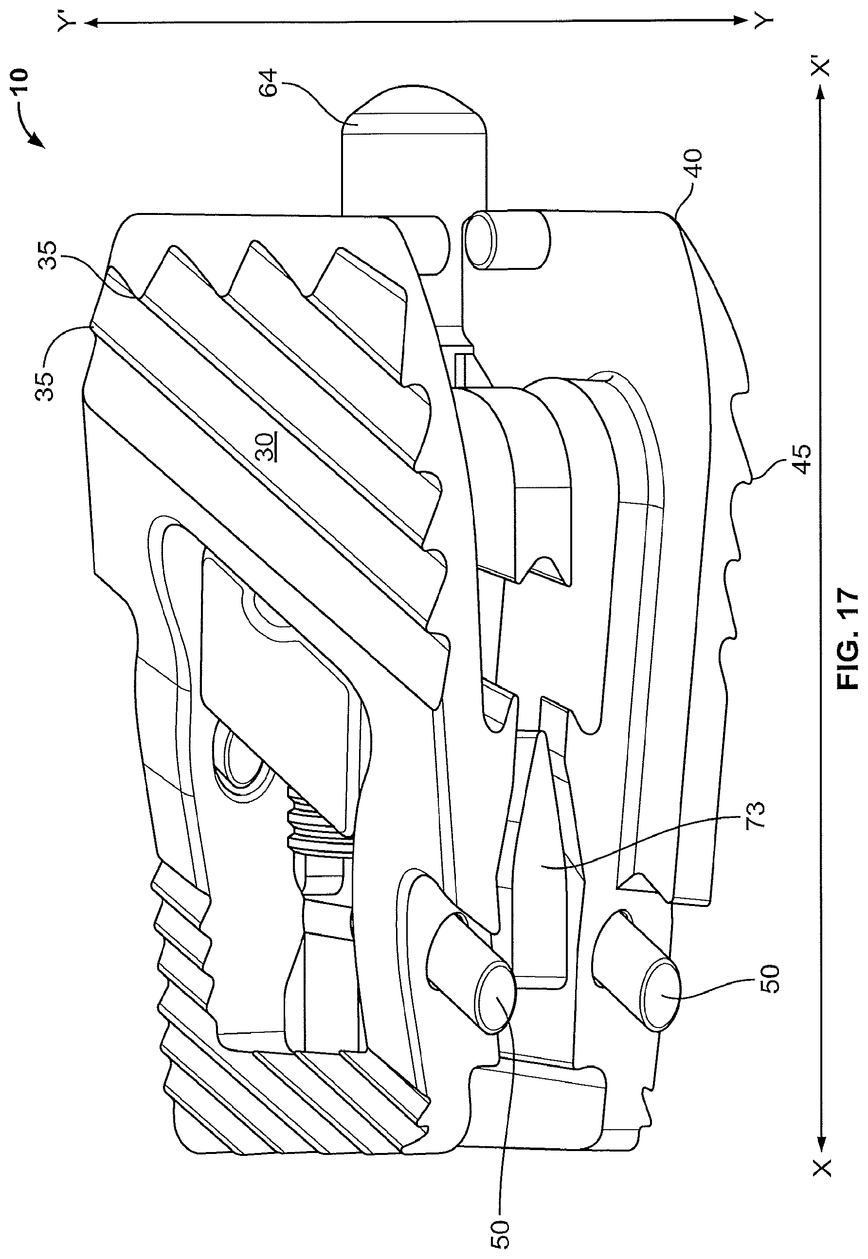
FIGS. 14-17 show perspective and cross sectional views of one embodiment of the expandable spinal implant of the present disclosure in the expanded and collapsed configurations.
FIG. 18 shows an alternate cross section view of the expandable spinal implant of the present disclosure in the expanded configuration.
FIG. 19 shows a side view of the expandable spinal implant of the present disclosure in the expanded configuration.
FIGS. 20 and 21 show one embodiment of the insertion tool of the present disclosure.
FIGS. 22-25 show various views of the measurement tool of the present disclosure.
SUMMARY OF THE DISCLOSURE
In a first aspect, the present disclosure provides an expandable spinal implant comprising a plurality of moveable endplates pivotably connect to a housing. In a second aspect, the present disclosure provides an expandable spinal implant comprising a plurality of moveable endplates pivotably connect to a housing, a central body, a lead screw engaged with the central body and a passive locking mechanism.
DETAILED DESCRIPTION
Unless otherwise defined, all terms used herein have the same meaning as commonly understood by one of ordinary skill in the art of this disclosure. It will be further understood that terms, such as those defined in commonly used dictionaries, should be interpreted as having a meaning that is consistent with their meaning in this context of the specification and should not be interpreted in an idealized or overly formal sense unless expressly so defined herein. Well known functions or constructions may not be described in detail herein for brevity or clarity.
The terminology used herein is for the purpose of describing particular embodiments only and is not intended to be limiting. As used herein, the singular foil is "a", "an" and "the" are intended to include the plural forms as well, unless the context clearly indicates otherwise.
The terms "about" and "approximately" shall generally mean an acceptable degree of error or variation for the quantity measured given the nature or precision of the measurements. Typical, exemplary degrees of error or variation are within 20 percent (%), preferably within 10%, and more preferably within 5% of a given value or range of values. Numerical quantities given herein are approximate unless stated otherwise, meaning that the term "about" or "approximately" can be inferred when not expressly stated.
Illustrative embodiments of the invention are described below. In the interest of clarity, not all features of an actual implementation are described in this specification. It will of course be appreciated that in the development of any such actual embodiment, numerous implementation-specific decisions must be made to achieve the developers' specific goals, such as compliance with system-related and business-related constraints, which will vary from one implementation to another. Moreover, it will be appreciated that such a development effort might be complex and time-consuming, but would nevertheless be a routine undertaking for those of ordinary skill in the art having the benefit of this disclosure. The expandable spinal fusion implant and related instruments disclosed herein boast a variety of novel features and components that warrant patent protection, both individually and in combination.
In general, the implant 10 described herein includes a housing 20, upper and lower moveable endplates 30, 40, a central body 70 positioned between the upper and lower endplates 30, 40 and within the housing 20, and a lead screw 60. The implant 10 is designed to be inserted into the disc space between adjacent vertebral bodies. The implant 10 may be made of any suitable, biocompatible material or combination of materials. For example, the implant components may be metal, poly ether ether ketone (PEEK), or a combination of the metal and PEEK. The implant 10 is configured to be inserted into the disc space in a collapsed state and upon being seated in a desired location within the disc space the distal end of the implant is expanded in height to create an implant 10 with a lordotic angle (i.e. the anterior height of the implant 10 is greater than the posterior height of the implant 10, thereby restoring a more natural lordotic curvature of the particular segment of the lumbar spine).
Now, referring to FIGS. 1-19, various embodiments of the implant 10 and its features and elements are shown. The implant 10 includes a housing 20 and upper and lower moveable endplates 30, 40 which are pivotably connected to the housing 20 via pins 50. The upper and lower moveable endplates 30, 40 are pivoted about the housing 20 by the action of a lead screw 60 coupled to a central body 70 as described herein.
The housing 20 is comprised of first and second lateral walls 21, 22 which are opposite one another and separated by a first and second end wall 23, 24 which are likewise opposite of one another. The first and second lateral walls 21, 22 and first and second end walls 23, 24 define a hollow or empty space which both serves to enclose the various elements required for expanding the implant 10 (as discussed in more detail below) and a fusion aperture 25. The housing may be shaped in a variety of shapes such as a parallelogram as depicted in the FIGS. 4B and C, of course rectangular and square configurations of the housing 20 should be considered within the scope of this disclosure. The first end wall 23 may be tapered to aid insertion into the disc space as shown in FIGS. 1 and 2. The first wall 23 also may include an aperture 27 which receives the rounded end 64 of the drive screw 60 to help secure the drive screw 60 in position. Further, the second end wall 24 comprises an aperture 27A through bone graft composition material can be passed into the fusion aperture 25 after the implant 10 is inserted.
The housing 20 may also have one or more fixed horizontal or nearly horizontal sections 28 that contact the vertebral bodies adjacent the disc space in which the implant 10 is inserted. The fixed horizontal section 28 may have anti-migration features 29 which help prevent shifting of the implant 10 insertion. The anti-migration features 29 may be teeth as depicted herein and may also be treated (for example, through a sandblasting like procedure) to produce a coarse or rough surface on the anti-migration features 29 to encourage bone growth.
The housing 20 may also comprise a recessed deck formed by a flat surface 26C. The recessed deck is configured to receive the upper and lower moveable endplates 30, 40 when the implant is in the collapsed configuration. The recessed deck is offset vertically towards the interior of the housing 20 from the fixed horizontal sections 28 and the vertical distance between the fixed horizontal section 28 and the flat surface 26C may be spanned by a ledge 26 as shown in FIGS. 2-4. In embodiments with the recessed deck, the housing 20 may also include a ramp 26B and a lip 26C on the tapered first end wall 22 of the implant 10. The ramp 26B and lip 26c serve to aid in the insertion of the implant 10 into the disc space while preventing tissue or other unwanted material from working its way into the space between the flat surface 26C and the upper and lower moveable endplates 30, 40.
As will be discussed in more detail below, the housing 20 also comprises portions of the passive locking mechanism as shown in FIGS. 2-4.
The implant 10 also includes upper and lower moveable endplates 30, 40. In the exemplary embodiment shown in FIGS. 1-19 and especially FIGS. 5-6, the upper and lower endplates 30, 40 are mirror images of one another, though it is contemplated that the upper and lower endplates may each have unique structural features. The upper and lower moveable endplates 30, 40 have bone contact surfaces 31, 41 which contact the vertebral bodies adjacent the disc space in which the implant 10 is inserted. The bone contact surfaces 31, 41 have anti-migration features 35, 45 which aid in preventing the implant 10 from shifting after insertion. The anti-migration features 35, 45 may be teeth as depicted herein and may also be treated (for example, through a sandblasting type procedure) that serves to produce a coarse or rough surface on the anti-migration features 35, 45 to encourage bone growth. The upper and lower moveable endplates 30, 40 are pivotable relative the housing 20 via the turning of the drive screw 60.
The upper and lower moveable endplates 30, 40 are pivotably connected to the housing 20 through pins 50 which pass through pin holes 52 in the housing 20 and the upper and lower moveable endplates 30, 40. In its collapsed configuration, the upper and lower moveable endplates 30, 40 lie flat or nearly flat in the recessed deck of the housing 20 on the flat surface 26C to aid in the insertion of the implant 10 into the disc space. For example, as shown in FIGS. 1-6, the upper and lower moveable endplates 30, 40 rest on flat surface 26C such that in the collapsed configuration the upper and lower moveable endplates 30, 40 are in horizontal alignment with the fixed horizontal sections 28. As the upper and lower end plates 30, 40 pivot relative to the housing 20, the angle of lordosis increases. In one embodiment, the implant 10 may provide between 1 and 40 degrees of lordosis.
The implant 10 also has a central body 70 between the upper and lower moveable endplates 30, 40 and at least partially surrounded by the housing 20. The central body 70 comprises a lead screw aperture 71 which is in vertical and horizontal alignment with the aperture 27 on the first end wall 23. The lead screw 60 may be inserted through the aperture 27 on the first end wall 23 until the rounded end 64 rests against, or abuts, the aperture 27 and the opposite end of the lead screw 60 is in the lead screw aperture 71 which comprises threads 72 complimentary to the threads 66 on the lead screw 60. The end of the lead screw 60 in the lead screw aperture 71 may comprise either a socket or other mechanism (such as a slotted or cross screwdriver head configuration) that can be connected to the insertion tool 100 through which the manipulation of the insertion tool 100 causes the lead screw 60 to turn. This end of the lead screw 60 is accessible via aperture 27A.
As the lead screw 60 turns in either the clockwise or counter-clockwise direction, the threads on the central body 70 cause the central body 70 to move laterally either towards the first end wall 23 or the second end wall 24 of the implant 10. In one embodiment, turning the lead screw 60 clockwise causes the central body 70 to move laterally towards the first end wall 23 while turning the lead screw 60 counter-clockwise causes the middle wall 70 to move laterally towards the second end wall 24 away from the first end wall 23.
As the central body 70 moves, wedges 73 contact ramps 36 on the interior surface of the upper and lower moveable endplates 30, 40 and cause the upper and lower endplates 30, 40 to rise outwardly away from the central body 70 (in other words, the upper and lower moveable endplates 30, 40 move towards the vertebral bodies above and below the disc space in which the implant has been inserted). Eventually, implant 10 is expanded the amount desired to restore the height of the intervertebral disc space. FIGS. 14-18 show the movement of the various parts of the implant 10 as it moves from the collapsed configuration to the expanded configuration.
FIG. 14 shows the implant 10 in the collapsed configuration ready for insertion along line x-x' into a disc space. FIG. 15 shows the same view of the implant as FIG. 14, but the housing 20 is not shown. In FIG. 15, the wedges 73 have not moved along the axis of line x-x' and therefore the upper and lower moveable endplates 30, 40 have not moved vertically along line y-y'. FIGS. 16 and 17 are similar views of the implant 10 as FIGS. 14 and 15, but the implant 10 is in the expanded configuration. As shown in FIGS. 16 and 17, in the expanded configuration the moveable upper and lower endplates 30, 40 have moved vertically along line y-y' by the movement of wedges 73 against ramps 36 along line x-x'.
Now referring to FIGS. 3-4 and 5-13, the implant 10 may also comprise a passive locking mechanism 80. As the patient returns to normal activity, the implant 10 will be subjected to forces and strains that could cause the lead screw 60 to back out thereby allowing the implant 10 to collapse as either the upper moveable endplate 30, the lower moveable endplate 40 or both retract from their extended position. The passive locking mechanism 80 prevents the lead screw 60 from working loose or backing out. There are several embodiments of the passive locking mechanism 80 contemplated by this disclosure.
In a first embodiment shown in FIGS. 11A-13, the passive locking mechanism comprises a locking collar 81 that is fitted to one end of the lead screw 60. The locking collar 81 is then positioned between the threads 66 of the lead screw 60 and the first end wall 23 where the lead screw 60 passes through the aperture 27. The locking collar 81 comprises one or more recess engagement tabs 82 that engages one or more recesses 83 (shown in FIG. 3) present on the interior surface of the first end wall 23 surrounding aperture 27. The one or more recess may be spaced evenly around the aperture 27. In one embodiment, the implant 10 comprises between two and twenty recesses 83. In alternate embodiments, the implant 10 comprises between eight and twelve recesses 83.
The locking collar 81 is affixed to the lead screw 60 so that as the lead screw 60 turns, the locking collar 81 also turns. As the amount of force applied to the lead screw 60 by the surgeon during implantation increases to an amount sufficient to cause the one or more recess engagement tabs 82 to be displaced from the one or more recesses 83, the one or more recess engagement tabs 82 will rotate towards the next recesses 83 until the one or more recess engagement tabs 82 settle or fall into the next recesses 83. If the surgeon then stops turning the lead screw 60 the locking collar 82 will stop turning as well. In this embodiment of the passive locking mechanism 80 the fitment of the one or more recess engagement tabs 82 into the one or more recesses 83 prevents the lead screw 60 from backing out as the forces and strains imparted on the locking collar 82 via the lead screw 60 through normal everyday patient activity will not be great enough to overcome the force securing the one or more recess engagement tabs 82 into the one or more recesses 83 and thus the lead screw 60 is locked in place.
In an alternate embodiment of the passive locking mechanism 80 shown in FIGS. 4 and 11B, the lead screw 60 comprises a lead screw collar 68 positioned between the rounded end 64 and the threads 66 which comprises one or more recesses 69 spaced round the lead screw collar 68. The interior surface of the first end wall 23 comprises the aperture 27 through which the lead screw 60 passes (as described above) and one or more extended arms 90 that extend from the first end wall 23 towards the center of the housing 20. The extended arms 90 comprise a recess engagement tab 91 with a bump that is configured to fit into the one or more recesses 69 on the lead screw collar 68. In a similar fashion to the first embodiment of the passive locking mechanism 80 described above, as the amount of force applied to the lead screw 60 by the surgeon during implantation increases to an amount sufficient to cause the one or more recess engagement tabs 91 to be displaced from the one or more recesses 69, the one or more recess engagement tabs 91 will rotate towards the next recesses 69 until the one or more recess engagement tabs 91 settle or fall into the recesses 69. In this embodiment of the passive locking mechanism 80 the fitment of the one or more recess engagement tabs 91 into the one or more recesses 69 prevents the lead screw 60 from backing out as the forces and strains imparted on the lead screw locking collar 81 via the lead screw 60 through normal everyday patient activity will not be great enough to overcome the force securing the one or more recess engagement tabs 91 into the one or more recesses 69 and thus the lead screw 60 is locked in place.
Additionally the implant 10 may comprise one or more anterior supports 74 on the central body 70. In order to achieve a successful surgical outcome in vertebral fusion surgeries, the amount of motion between the implant 10 and the adjacent vertebral bodies needs to be minimized--this may be accomplished by the use of screws, rods and/or plates as is well known in the art. Additionally, the motion within the implant 10 itself needs to be minimized as well. As discussed above, the one or more wedges 73 serve to either lift or lower the upper and lower moveable endplates 30, 40 and the one or more wedges 73 also provide support for the upper and lower moveable endplates 30, 40 to prevent them from collapsing. However, it may be advantage to provide a second means of support such as the one or more anterior supports 74 to prevent the upper and lower moveable endplates 30, 40 from pivoting around the one or more pins 50. The one or more anterior supports 74 extend axially from the central body (see, e.g., FIG. 7A) opposite the one or more wedges 73. When the upper and lower moveable endplates are raised and the implant 10 is in the expanded configuration, one end of the upper and lower moveable endplates 30, 40 will contact the one or more anterior supports thereby preventing the upper and lower moveable endplates 30, 40 from rotating about the pins 50 thus minimizing the amount of movement within the implant 10 after insertion.
The present disclosure also provides an insertion tool 100, as shown in FIGS. 20 and 21, that engages with the implant 10 and aids in the insertion of the implant 10 during surgery. The insertion tool 100 comprises a rotatable element 101 in the end opposite the attachment point 102 with the implant 10. The rotatable element 102 may be in communication with the implant and specifically the lead screw 60 so that as the rotatable element 101 is rotated by the surgeon the lead screw 60 likewise rotates thus translating the wedges 73 and moving the upper and lower moveable endplates 30, 40. The attachment point 101 serves to provide a reversible, yet secure means of attaching the implant 10 to the insertion tool 100. The implant 10 may be attached to the insertion tool 100 prior to insertion of the implant between the vertebral bodies and may be unattached by the surgeon from the insertion tool 100 after insertion between the vertebral bodies. The means of attaching the implant 10 to the insertion tool 100 should allow the implant to be unattached from the insertion tool 100 quickly and easily so as to not disturb the implant after insertion.
The insertion tool 100 may comprise a hollow cylinder running its length. The hollow cylinder allows a surgeon to pack or insert bone graft composition into the fusion aperture 25 in the implant 10 after insertion and after the implant 10 is in its expanded configuration. As shown in FIG. 21, it may be desirable to use a funnel 103 to aid in the packing of the bone graft composition into the hollow cylinder of the insertion tool 100.
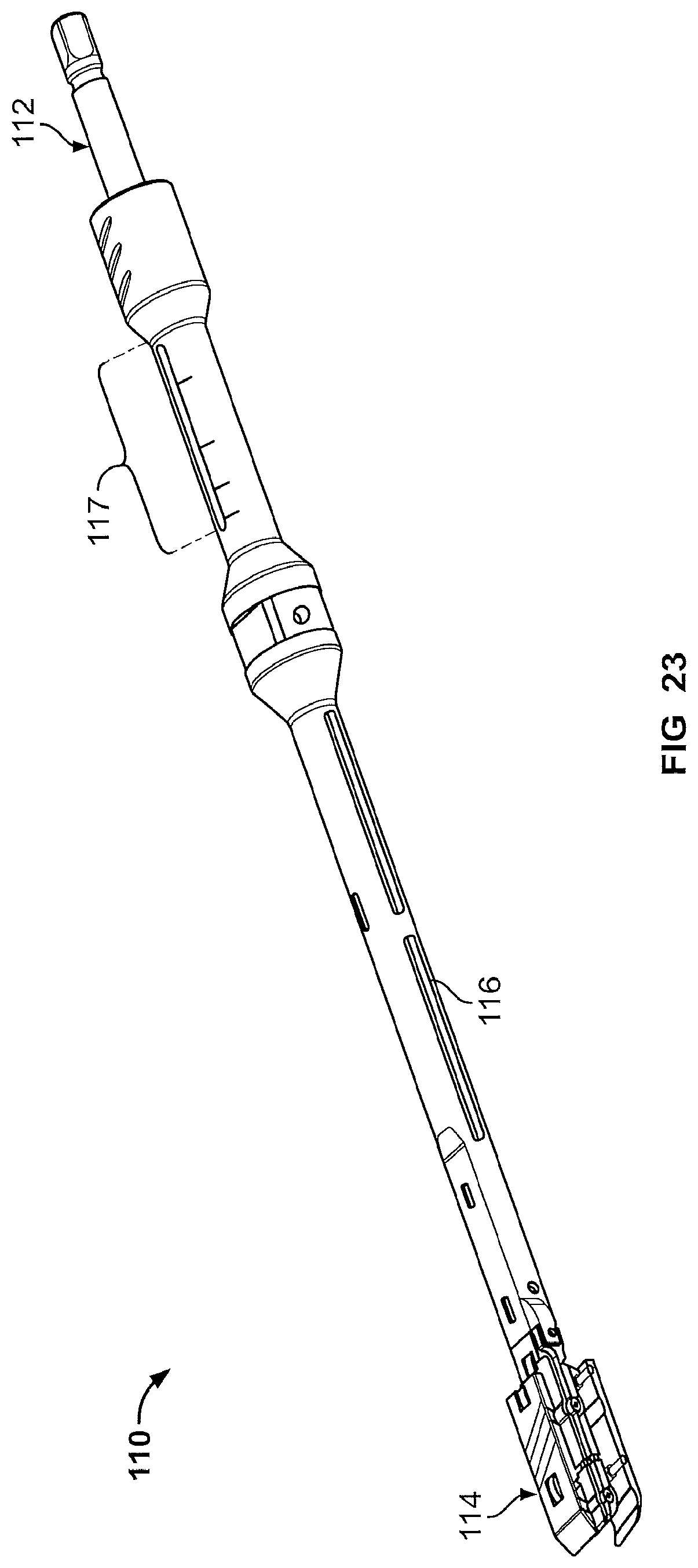
In another aspect, the present disclosure provides a measurement tool 110 useful for determining the approximate height required by the implant 10 upon insertion between vertebral bodies. One embodiment of this measurement tool is shown in FIGS. 22-25. The measurement tool comprises a first end 111 with a driver 112 and a second end 113 with two moveable endplates 114.
The driver 112 is rotatable and as it rotates, its rotational movement is translated by a series of linkages 115 located in the shaft 116 of the measurement tool 110 into a force that expands the moveable endplates 114. The endplates 114 at attached to a series of arms 117 which are in turn attached to the linkages 115. As the driver 112 rotates, the endplates 114 may be either raised away from the shaft 116 or lowered towards it.
The measurement tool 110 may also comprise an indicator feature 117 near the first end 111 that visually translates the movement of the endplates 114 into a series of predetermined units so that the surgeon can observe the movement of the endplates via the indicator feature 117. For example, the indicator feature may comprise an aperture on the shaft 116 that has a range of numbers from 1-10 printed (such as by laser printing) around the end of the aperture. As the endplates 114 are inserted between the vertebral bodies in their collapsed configuration, the indicator feature may have some marker correlating the height of the endplates 114 in the collapsed position to position "1" and as the endplates 114 are moved into their expanded configuration by the rotation of the driver 112, the marker may move from position "1" to position "2", "3", etc. The position numbers may then be correlated with the actual height of the endplates 114 providing the surgeon an estimate of the height of implant 10 for the particular patient's anatomy. Alternatively the numbers provided on the indicator feature 117 may directly provide the height of the endplates 114--in other words, the numbers may represent the height, in millimeters, of the endplates in the expanded configuration.
Although particular embodiments of the present disclosure have been described, it is not intended that such references be construed as limitations upon the scope of this disclosure except as set forth in the claims.
* * * * *
D00000
D00001
D00002
D00003
D00004
D00005
D00006
D00007
D00008
D00009
D00010
D00011
D00012
D00013

D00014
D00015

D00016

D00017
D00018

D00019

D00020
D00021

D00022

D00023

D00024

D00025

D00026
D00027

D00028

XML
uspto.report is an independent third-party trademark research tool that is not affiliated, endorsed, or sponsored by the United States Patent and Trademark Office (USPTO) or any other governmental organization. The information provided by uspto.report is based on publicly available data at the time of writing and is intended for informational purposes only.
While we strive to provide accurate and up-to-date information, we do not guarantee the accuracy, completeness, reliability, or suitability of the information displayed on this site. The use of this site is at your own risk. Any reliance you place on such information is therefore strictly at your own risk.
All official trademark data, including owner information, should be verified by visiting the official USPTO website at www.uspto.gov. This site is not intended to replace professional legal advice and should not be used as a substitute for consulting with a legal professional who is knowledgeable about trademark law.