Microcatheter sensor design for minimizing profile and impact of wire strain on sensor
McCaffrey , et al. April 13, 2
U.S. patent number 10,973,418 [Application Number 14/920,722] was granted by the patent office on 2021-04-13 for microcatheter sensor design for minimizing profile and impact of wire strain on sensor. This patent grant is currently assigned to MEDTRONIC VASCULAR, INC.. The grantee listed for this patent is Medtronic Vascular, Inc.. Invention is credited to Gerry McCaffrey, Christopher Murphy, Fiachra Sweeney, Sean Ward.


| United States Patent | 10,973,418 |
| McCaffrey , et al. | April 13, 2021 |
Microcatheter sensor design for minimizing profile and impact of wire strain on sensor
Abstract
A catheter, such as a fractional flow reserve catheter, includes an elongate shaft having a pressure sensing wire extending to the distal portion of the elongate shaft. The wire has a pressure sensor mounted on the distal end for measuring a pressure of a fluid within lumen of vessel. The pressure sensor wire is disposed within a pocket formed adjacent to the pressure sensor thereby minimizing the profile of the catheter. Bending stresses experienced by a pressure sensor mounted to a fractional flow reserve catheter when tracking the catheter through the vasculature creates a distortion of the sensor resulting in an incorrect pressure reading or bend error. In order to isolate the sensor from bending stresses, the sensor is spaced apart from the pressure sensor wire to allow the pressure sensor and the pressure sensor wire to move independently from one another.
| Inventors: | McCaffrey; Gerry (Ballybrit, IE), Murphy; Christopher (Ballybrit, IE), Ward; Sean (Ballybrit, IE), Sweeney; Fiachra (Ballybrit, IE) | ||||||||||
|---|---|---|---|---|---|---|---|---|---|---|---|
| Applicant: |
|
||||||||||
| Assignee: | MEDTRONIC VASCULAR, INC. (Santa
Rosa, CA) |
||||||||||
| Family ID: | 1000005482487 | ||||||||||
| Appl. No.: | 14/920,722 | ||||||||||
| Filed: | October 22, 2015 |
Prior Publication Data
| Document Identifier | Publication Date | |
|---|---|---|
| US 20160081564 A1 | Mar 24, 2016 | |
Related U.S. Patent Documents
| Application Number | Filing Date | Patent Number | Issue Date | ||
|---|---|---|---|---|---|
| 14595884 | Jan 13, 2015 | 10201284 | |||
| 62068052 | Oct 24, 2014 | ||||
| 62012628 | Jun 16, 2014 | ||||
| Current U.S. Class: | 1/1 |
| Current CPC Class: | A61B 5/6852 (20130101); A61B 5/02141 (20130101); A61B 5/0215 (20130101); A61B 5/02007 (20130101); A61B 2562/0247 (20130101) |
| Current International Class: | A61B 5/021 (20060101); A61B 5/0215 (20060101); A61B 5/00 (20060101); A61B 5/02 (20060101) |
References Cited [Referenced By]
U.S. Patent Documents
| 4718425 | January 1988 | Tanaka et al. |
| 4771782 | September 1988 | Millar |
| 4796641 | January 1989 | Mills |
| 4815472 | March 1989 | Wise |
| 4850358 | July 1989 | Millar |
| 4901731 | February 1990 | Millar |
| 4924877 | May 1990 | Brooks |
| 4928693 | May 1990 | Goodin |
| 4936310 | June 1990 | Engstrom et al. |
| 4941473 | July 1990 | Tenerz et al. |
| 4966148 | October 1990 | Millar |
| 4966156 | October 1990 | Perry et al. |
| 5029585 | July 1991 | Lieber et al. |
| 5046497 | September 1991 | Millar |
| 5050297 | September 1991 | Metzger |
| 5085223 | February 1992 | Lars et al. |
| 5125058 | June 1992 | Tenerz et al. |
| 5195375 | March 1993 | Tenerz et al. |
| 5267958 | December 1993 | Buchbinder et al. |
| 5280786 | January 1994 | Wlodarczyk et al. |
| 5427114 | June 1995 | Colliver et al. |
| 5451233 | September 1995 | Yock |
| 5466222 | November 1995 | Ressemann et al. |
| 5526820 | June 1996 | Khoury |
| 5542434 | August 1996 | Imran et al. |
| 5564425 | October 1996 | Tonokura |
| 5569219 | October 1996 | Hakki et al. |
| 5573007 | November 1996 | Bobo, Sr. |
| 5591129 | January 1997 | Shoup et al. |
| 5637091 | June 1997 | Hakky et al. |
| RE35648 | November 1997 | Tenerz et al. |
| 5694946 | December 1997 | Tenerz et al. |
| 5701905 | December 1997 | Esch |
| 5715827 | February 1998 | Cori et al. |
| 5813997 | September 1998 | Imran et al. |
| 5827243 | October 1998 | Palestrant |
| 5873835 | February 1999 | Hastings |
| 5902248 | May 1999 | Millar et al. |
| 5964714 | October 1999 | Lafontaine |
| 6033366 | March 2000 | Brockway |
| 6056719 | May 2000 | Mickley |
| 6089103 | July 2000 | Smith |
| 6106476 | August 2000 | Corl et al. |
| 6106486 | August 2000 | Tenerz et al. |
| 6112598 | September 2000 | Tenerz et al. |
| 6142958 | November 2000 | Hammarstrom et al. |
| 6167763 | January 2001 | Tenerz et al. |
| 6179856 | January 2001 | Barbere |
| 6182513 | February 2001 | Stemme et al. |
| 6193669 | February 2001 | Degany |
| 6224585 | May 2001 | Pfeiffer |
| 6248083 | June 2001 | Smith et al. |
| 6296615 | October 2001 | Brockway et al. |
| 6312380 | October 2001 | Brockway et al. |
| 6336906 | January 2002 | Hammarstrom et al. |
| 6354999 | March 2002 | Dgany |
| 6379308 | April 2002 | Brockway et al. |
| 6394986 | May 2002 | Millar |
| 6409677 | June 2002 | Tulkki |
| 6471656 | October 2002 | Shalman et al. |
| 6517481 | February 2003 | Hoek et al. |
| 6546804 | April 2003 | Stemme et al. |
| 6551250 | April 2003 | Khalil |
| 6565514 | May 2003 | Svanerudh et al. |
| 6585660 | July 2003 | Dorando et al. |
| 6615067 | September 2003 | Hoek et al. |
| 6615667 | September 2003 | Smith |
| 6659957 | December 2003 | Vardi et al. |
| 6659959 | December 2003 | Brockway et al. |
| 6663570 | December 2003 | Mott et al. |
| 6716178 | April 2004 | Kilpatrick et al. |
| 6733459 | May 2004 | Atsumi |
| 6754608 | June 2004 | Svanrudh et al. |
| 6767327 | July 2004 | Cori et al. |
| 6821287 | November 2004 | Jang |
| 6868736 | March 2005 | Sawatari et al. |
| 6926674 | August 2005 | Tenerz et al. |
| 6938474 | September 2005 | Melvas |
| 6966890 | November 2005 | Coyle et al. |
| 6974422 | December 2005 | Millar |
| 6976965 | December 2005 | Corl et al. |
| 6993974 | February 2006 | Tenerz et al. |
| 6994695 | February 2006 | Millar |
| 7017416 | March 2006 | Liu et al. |
| 7021152 | April 2006 | Tenerz |
| 7025727 | April 2006 | Brockway |
| 7060038 | June 2006 | Letort et al. |
| 7097620 | August 2006 | Cori et al. |
| 7112170 | September 2006 | Schock et al. |
| 7134994 | November 2006 | Alpert et al. |
| 7137953 | November 2006 | Eigler et al. |
| 7211048 | May 2007 | Najafi |
| 7222539 | May 2007 | Tulkki |
| 7229403 | June 2007 | Schock |
| 7245789 | July 2007 | Bates et al. |
| 7263894 | September 2007 | Tenerz |
| 7274956 | September 2007 | Mott et al. |
| RE39863 | October 2007 | Smith |
| 7294117 | November 2007 | Provost-Tine et al. |
| 7329223 | February 2008 | Ainsworth et al. |
| 7331236 | February 2008 | Smith et al. |
| 7343811 | March 2008 | Tenerz et al. |
| 7347822 | March 2008 | Brockway |
| 7447388 | November 2008 | Bates et al. |
| 7450989 | November 2008 | Svanerudh |
| 7454244 | November 2008 | Kassab et al. |
| 7458938 | December 2008 | Patel et al. |
| 7472601 | January 2009 | Tenerz et al. |
| 7481774 | January 2009 | Brockway et al. |
| 7527594 | May 2009 | Vardi et al. |
| 7532920 | May 2009 | Ainsworth et al. |
| 7599588 | October 2009 | Eberle et al. |
| 7645233 | January 2010 | Tulkki et al. |
| 7660492 | February 2010 | Bates et al. |
| 7724148 | May 2010 | Samuelsson et al. |
| 7731664 | June 2010 | Millar |
| 7775988 | August 2010 | Pijls |
| 7783338 | August 2010 | Ainsworth et al. |
| 7837650 | November 2010 | Cox et al. |
| 7881573 | February 2011 | Eberle et al. |
| 7931603 | April 2011 | Von Malmborg et al. |
| 7946997 | May 2011 | Hubinette |
| 7967761 | June 2011 | Smith |
| 7967762 | June 2011 | Cori et al. |
| 7998089 | August 2011 | Smith |
| 8025623 | September 2011 | Millar |
| 8029447 | October 2011 | Kanz et al. |
| 8059923 | November 2011 | Bates et al. |
| 8140146 | March 2012 | Kim et al. |
| 8157742 | April 2012 | Taylor |
| 8162856 | April 2012 | Williams et al. |
| 8174395 | May 2012 | Samuelsson |
| 8187195 | May 2012 | Tulkki |
| 8216151 | July 2012 | Smith |
| 8231537 | July 2012 | Ahmed et al. |
| 8249815 | August 2012 | Taylor |
| 8277386 | October 2012 | Ahmed et al. |
| 8282565 | October 2012 | Mahapatra et al. |
| 8298156 | October 2012 | Manstrom et al. |
| 8311747 | November 2012 | Taylor |
| 8311748 | November 2012 | Taylor et al. |
| 8311750 | November 2012 | Taylor |
| 8315812 | November 2012 | Taylor |
| 8315813 | November 2012 | Taylor et al. |
| 8315814 | November 2012 | Taylor et al. |
| 8317715 | November 2012 | Belleville et al. |
| 8320723 | November 2012 | Eberle et al. |
| 8321150 | November 2012 | Taylor |
| 8410940 | April 2013 | Samuelsson |
| 8419647 | April 2013 | Corl et al. |
| 8419648 | April 2013 | Corl et al. |
| 8461997 | June 2013 | Samuelsson |
| 8485985 | July 2013 | Manstrom |
| 8556520 | October 2013 | Elenbaas et al. |
| 8562537 | October 2013 | Alpert et al. |
| 8636659 | January 2014 | Alpert et al. |
| 8641639 | February 2014 | Manstrom |
| 8696584 | April 2014 | Kassab |
| 8698638 | April 2014 | Samuelsson et al. |
| 8714021 | May 2014 | Gamage |
| 8797155 | August 2014 | Huennekens et al. |
| 8857264 | October 2014 | Gamage |
| 8860851 | October 2014 | Goma et al. |
| 8958863 | February 2015 | Huennekens et al. |
| 8977336 | March 2015 | Huennekens et al. |
| 8998823 | April 2015 | Manstrom et al. |
| 9011342 | April 2015 | Manstrom et al. |
| 9113843 | August 2015 | Manstrom et al. |
| 9186072 | November 2015 | Manstrom et al. |
| 9220461 | December 2015 | Samuelsson et al. |
| 9259161 | February 2016 | Suchecki et al. |
| 9289137 | March 2016 | Corl |
| 9314584 | April 2016 | Riley et al. |
| 9332916 | May 2016 | Kassab |
| 9339348 | May 2016 | Davies et al. |
| 2001/0051769 | December 2001 | Hoek et al. |
| 2002/0013527 | January 2002 | Hoek et al. |
| 2002/0035331 | March 2002 | Brockway et al. |
| 2002/0059827 | May 2002 | Smith |
| 2002/0065472 | May 2002 | Brockway et al. |
| 2002/0072880 | June 2002 | Svanerudh et al. |
| 2002/0157473 | October 2002 | Stemme et al. |
| 2002/0173724 | November 2002 | Dorando et al. |
| 2003/0018273 | January 2003 | Corl et al. |
| 2003/0032886 | February 2003 | Dgany et al. |
| 2003/0033095 | February 2003 | Svanerudh et al. |
| 2003/0040674 | February 2003 | Corl et al. |
| 2003/0159518 | August 2003 | Sawatari et al. |
| 2003/0163052 | August 2003 | Mott et al. |
| 2003/0176850 | September 2003 | Melvas |
| 2003/0195428 | October 2003 | Brockway et al. |
| 2003/0216621 | November 2003 | Alpert et al. |
| 2004/0067000 | April 2004 | Bates et al. |
| 2004/0082844 | April 2004 | Vardi et al. |
| 2004/0082866 | April 2004 | Mott et al. |
| 2004/0116816 | June 2004 | Tenerz et al. |
| 2004/0143240 | July 2004 | Armstrong et al. |
| 2004/0143261 | July 2004 | Hartley et al. |
| 2004/0157790 | August 2004 | Herweijer et al. |
| 2004/0162548 | August 2004 | Reiser |
| 2004/0167385 | August 2004 | Rioux et al. |
| 2004/0176790 | September 2004 | Coyle |
| 2004/0230131 | November 2004 | Kassab et al. |
| 2004/0254442 | December 2004 | Williams et al. |
| 2005/0000294 | January 2005 | Tenerz et al. |
| 2005/0011272 | January 2005 | Tenerz |
| 2005/0043670 | February 2005 | Rosenberg |
| 2005/0049451 | March 2005 | Schock et al. |
| 2005/0187487 | August 2005 | Azizkhan |
| 2005/0268724 | December 2005 | Tenerz |
| 2005/0268725 | December 2005 | Tulkki |
| 2006/0052700 | March 2006 | Svanerudh |
| 2006/0074318 | April 2006 | Ahmed et al. |
| 2006/0094966 | May 2006 | Brockway et al. |
| 2006/0094982 | May 2006 | Corl et al. |
| 2006/0142756 | June 2006 | Davies et al. |
| 2006/0207335 | September 2006 | Tenerz et al. |
| 2006/0241505 | October 2006 | Ahmed et al. |
| 2006/0287569 | December 2006 | Schock et al. |
| 2007/0060820 | March 2007 | Lofgren et al. |
| 2007/0060822 | March 2007 | Alpert et al. |
| 2007/0078352 | April 2007 | Pijls |
| 2007/0106142 | May 2007 | Von Malmborg et al. |
| 2007/0106165 | May 2007 | Tulkki |
| 2007/0116408 | May 2007 | Eberle et al. |
| 2007/0133925 | June 2007 | Bates et al. |
| 2007/0135718 | June 2007 | Corl et al. |
| 2007/0162106 | July 2007 | Evans et al. |
| 2007/0191717 | August 2007 | Rosen et al. |
| 2007/0220986 | September 2007 | Smith et al. |
| 2007/0255144 | November 2007 | Tulkki et al. |
| 2007/0255145 | November 2007 | Smith |
| 2008/0077085 | March 2008 | Eidenschink et al. |
| 2008/0119739 | May 2008 | Vardi et al. |
| 2008/0119758 | May 2008 | Samuelsson et al. |
| 2008/0132806 | June 2008 | Smith |
| 2008/0139897 | June 2008 | Ainsworth et al. |
| 2008/0146993 | June 2008 | Krishna |
| 2008/0200770 | August 2008 | Hubinette |
| 2008/0255471 | October 2008 | Maghavi et al. |
| 2008/0262470 | October 2008 | Lee et al. |
| 2008/0269572 | October 2008 | Kanz et al. |
| 2008/0269581 | October 2008 | Wood et al. |
| 2009/0059727 | March 2009 | Bates et al. |
| 2009/0082678 | March 2009 | Smith |
| 2009/0088609 | April 2009 | Schmitz-Rode et al. |
| 2009/0088650 | April 2009 | Cori |
| 2009/0124880 | May 2009 | Smith |
| 2009/0125007 | May 2009 | Splinter |
| 2009/0248049 | October 2009 | Perkins |
| 2009/0281394 | November 2009 | Russell et al. |
| 2010/0014810 | January 2010 | Eberle et al. |
| 2010/0087732 | April 2010 | Eberle et al. |
| 2010/0109104 | May 2010 | Tiensuu et al. |
| 2010/0113942 | May 2010 | Eberle |
| 2010/0135111 | June 2010 | Bates et al. |
| 2010/0152607 | June 2010 | Kassab |
| 2010/0174201 | July 2010 | Bodecker et al. |
| 2010/0234698 | September 2010 | Manstrom et al. |
| 2010/0241008 | September 2010 | Belleville et al. |
| 2010/0280330 | November 2010 | Samuelsson et al. |
| 2010/0286536 | November 2010 | Samuelsson et al. |
| 2010/0286537 | November 2010 | Pijls |
| 2011/0004198 | January 2011 | Hoch |
| 2011/0060229 | March 2011 | Hulvershorn |
| 2011/0066047 | March 2011 | Belleville et al. |
| 2011/0071407 | March 2011 | Hubinette et al. |
| 2011/0083521 | April 2011 | Hollander et al. |
| 2011/0123154 | May 2011 | Eberle et al. |
| 2011/0137140 | June 2011 | Tearney et al. |
| 2011/0178383 | July 2011 | Kassab |
| 2011/0178413 | July 2011 | Schmitt et al. |
| 2011/0178417 | July 2011 | Kassab |
| 2011/0196255 | August 2011 | Kassab |
| 2011/0245693 | October 2011 | Hastings et al. |
| 2011/0251497 | October 2011 | Corl et al. |
| 2011/0306867 | December 2011 | Gopinathan et al. |
| 2011/0319773 | December 2011 | Kanz et al. |
| 2012/0053918 | March 2012 | Taylor |
| 2012/0071782 | March 2012 | Patil et al. |
| 2012/0072190 | March 2012 | Sharma et al. |
| 2012/0101355 | April 2012 | Gopinathan et al. |
| 2012/0101369 | April 2012 | Patil et al. |
| 2012/0108943 | May 2012 | Bates et al. |
| 2012/0136244 | May 2012 | Manstrom et al. |
| 2012/0172731 | July 2012 | Smith |
| 2012/0172732 | July 2012 | Meyer |
| 2012/0203118 | August 2012 | Samuelsson et al. |
| 2012/0220836 | August 2012 | Alpert et al. |
| 2012/0220837 | August 2012 | Alpert et al. |
| 2012/0220883 | August 2012 | Manstrom et al. |
| 2012/0227505 | September 2012 | Belleville et al. |
| 2012/0265079 | October 2012 | Hilmersson |
| 2012/0271178 | October 2012 | Smith |
| 2012/0278008 | November 2012 | Davies et al. |
| 2012/0316419 | December 2012 | Chevalier |
| 2013/0015975 | January 2013 | Huennekens et al. |
| 2013/0023762 | January 2013 | Huennekens et al. |
| 2013/0023763 | January 2013 | Huennekens et al. |
| 2013/0046190 | February 2013 | Davies |
| 2013/0060133 | March 2013 | Kassab et al. |
| 2013/0090555 | April 2013 | Kassab |
| 2013/0096409 | April 2013 | Hiltner et al. |
| 2013/0109980 | May 2013 | Teo |
| 2013/0116579 | May 2013 | Svanerudh |
| 2013/0131523 | May 2013 | Suchecki et al. |
| 2013/0190633 | July 2013 | Dorando et al. |
| 2013/0216481 | August 2013 | Rosenmeier |
| 2013/0303914 | November 2013 | Hiltner et al. |
| 2013/0324864 | December 2013 | Manstrom |
| 2014/0024235 | January 2014 | Russell |
| 2014/0024950 | January 2014 | Hiltner et al. |
| 2014/0086461 | March 2014 | Yao et al. |
| 2014/0180140 | June 2014 | Alpert |
| 2014/0180141 | June 2014 | Millett |
| 2014/0187980 | July 2014 | Burkett |
| 2014/0187984 | July 2014 | Burkett |
| 2014/0276142 | September 2014 | Dorando |
| 2014/0296687 | October 2014 | Irazoqui et al. |
| 2014/0379269 | December 2014 | Schmitt |
| 2015/0032011 | January 2015 | McGowan et al. |
| 2015/0074995 | March 2015 | Patil et al. |
| 2015/0105673 | April 2015 | Gregorich |
| 2015/0112191 | April 2015 | Gilboa et al. |
| 2015/0141853 | May 2015 | Miller et al. |
| 2015/0148693 | May 2015 | Burkett |
| 2015/0157216 | June 2015 | Stigall et al. |
| 2015/0173722 | June 2015 | Huennekens et al. |
| 2015/0223707 | August 2015 | Ludoph |
| 2015/0265167 | September 2015 | McGowan et al. |
| 2015/0272449 | October 2015 | Meyer |
| 2015/0282765 | October 2015 | Goshen et al. |
| 2015/0313479 | November 2015 | Stigall et al. |
| 2015/0359438 | December 2015 | McCaffrey et al. |
| 2015/0359439 | December 2015 | Manstrom et al. |
| 2016/0022153 | January 2016 | Dorando |
| 2016/0022956 | January 2016 | Purdy et al. |
| 2016/0066802 | March 2016 | Keller |
| 2016/0106321 | April 2016 | Sharma et al. |
| 101983031 | Mar 2011 | CN | |||
| 102008045878 | Mar 2010 | DE | |||
| 0263190 | Oct 1986 | EP | |||
| 1260175 | Nov 2002 | EP | |||
| 1493381 | Jan 2005 | EP | |||
| 1165171 | Mar 2005 | EP | |||
| 1514512 | Mar 2005 | EP | |||
| 1658808 | May 2006 | EP | |||
| 1702641 | Sep 2006 | EP | |||
| 1498068 | Mar 2007 | EP | |||
| 01419796 | Mar 2008 | EP | |||
| 10033488 | Feb 1998 | JP | |||
| 10137199 | May 1998 | JP | |||
| 2000-333913 | Dec 2000 | JP | |||
| 2004194996 | Jul 2004 | JP | |||
| 2005-3638066 | Jan 2005 | JP | |||
| 2005-095603 | Apr 2005 | JP | |||
| 2005-3705458 | Aug 2005 | JP | |||
| 2006-204378 | Aug 2006 | JP | |||
| 2009285 | Feb 2014 | NL | |||
| WO1997/000641 | Jan 1997 | WO | |||
| WO1999/058059 | Nov 1999 | WO | |||
| WO2003/022122 | Mar 2003 | WO | |||
| WO2006/037082 | Apr 2006 | WO | |||
| WO2006/0117154 | Nov 2006 | WO | |||
| WO2011/120565 | Oct 2011 | WO | |||
| WO2011/0161212 | Dec 2011 | WO | |||
| WO2012/093260 | Jul 2012 | WO | |||
| WO2012/173697 | Dec 2012 | WO | |||
| WO2013/061281 | May 2013 | WO | |||
| WO2014/025255 | Feb 2014 | WO | |||
| WO2014/176448 | Oct 2014 | WO | |||
| 2015/073423 | May 2015 | WO | |||
| 2015/164006 | Oct 2015 | WO | |||
| WO2015/150128 | Oct 2015 | WO | |||
| WO2016/001017 | Jan 2016 | WO | |||
Other References
|
PCT/US2015/033602, The International Search Report and the Written Opinion of the International Searching Authority, dated Sep. 2, 2015. cited by applicant . PCT/US2015/057058, The International Search Report and the Written Opinion of the International Searching Authority, dated Apr. 20, 2016. cited by applicant . PCT/US2017/022637, The International Search Report and the Written Opinion of the International Searching Authority, dated Jul. 12, 2017, 12pages. cited by applicant . Final Office Actioin dated Mar. 13, 2018 in co-pending U.S. Appl. No. 14/595,884. cited by applicant . Advisory Action dated Jun. 1, 2018 in co-pending U.S. Appl. No. 14/595,884. cited by applicant . Non-Final Office Action issued in U.S. Appl. No. 15/077,964, dated Jan. 2, 2019. cited by applicant . Non-Final Office Action issued Nov. 16, 2019 in U.S. Appl. No. 15/077,964. cited by applicant . Office Action dated Apr. 2, 2020, in Chinese Application No. 201580032242.1 (with English Translation). cited by applicant . Office Action dated Jul. 8 2020, in Chinese Application No. 201730018289.1 (with English Translation). cited by applicant. |
Primary Examiner: Wilson; Kaylee R
Assistant Examiner: Shah; Jay B
Attorney, Agent or Firm: Medler Ferro Woodhouse & Mills PLLC
Parent Case Text
RELATED APPLICATIONS
This application is a continuation-in-part of application Ser. No. 14/595,884, filed Jan. 13, 2015, which claims the benefit under 35 U.S.C. .sctn. 119 of U.S. Provisional Patent Application No. 62/012,628 filed on Jun. 15, 2014. The present application also claims the benefit under 35 U.S.C. .sctn. 119 of U.S. Provisional Patent Application No. 62/068,052 filed on Oct. 24, 2014 and titled MICROCATHETER SENSOR DESIGN FOR MINIMIZING PROFILE AND IMPACT OF WIRE STRAIN ON SENSOR.
Claims
What is claimed is:
1. A catheter comprising: an elongate shaft including a proximal portion and a distal portion, the elongate shaft having a shaft wall, the shaft wall having an outer surface and an inner surface, the inner surface of the shaft wall defining a guidewire lumen; and a pressure sensor having a first end and a second end coupled to the outer surface of the shaft wall at the distal end of the elongate shaft, wherein the pressure sensor is coupled to the outer surface of the shaft wall at the first end of the pressure sensor such that the second end of the pressure sensor is unsupported and spaced apart from the outer surface of the shaft wall to form an overhang to define a first pocket between the overhang and the outer surface of the shaft wall formed such that the pressure sensor is surrounded and contacted by blood when the catheter is inserted into vasculature, wherein the pressure sensor has a first surface and a second surface opposite the first surface and a diaphragm on the first surface, wherein an electrical coupling member is coupled to the second surface of the pressure sensor and disposed in a second pocket formed between the second surface of the pressure sensor and the outer surface of the shaft wall.
2. The catheter of claim 1, wherein the pressure sensor is mounted to a step extending from the outer surface of the shaft wall.
3. The catheter of claim 2, wherein the pressure sensor is mounted to the step at a location that is adjacent to the first end of the pressure sensor thereby forming the overhang.
4. The catheter of claim 2, wherein the first pocket is defined by the overhang, the step and the outer surface of the shaft wall.
5. The catheter of claim 2, wherein the first pocket is further defined by side walls extending from the outer surface of the shaft wall, the side walls being disposed on either side of the pocket between the step and the overhang.
Description
FIELD OF THE INVENTION
The invention relates to methods and systems for determining a pressure gradient across a lesion of a vessel for calculating a Fractional Flow Reserve.
BACKGROUND OF THE INVENTION
The severity of a stenosis or lesion in a blood vessel may be assessed by obtaining proximal and distal pressure measurements relative to the given stenosis and using those measurements for calculating a value of the Fractional Flow Reserve (FFR). FFR is defined as the ratio of a first pressure measurement (P.sub.d) taken on the distal side of the lesion and to a second pressure measurement taken on the proximal side of the lesion usually within the aorta (P.sub.a). Conventionally, a sensor is placed on the distal portion of a guidewire or FFR wire to obtain the first pressure measurement P.sub.d, while an external pressure transducer is fluidly connected via tubing to a guide catheter for obtaining the second or aortic (AO) pressure measurement P.sub.a. Calculation of the FFR value provides a lesion specific index of the functional severity of the stenosis in order to determine whether the blockage limits blood flow within the vessel to an extent that treatment is needed. An optimal or normal value of FFR in a healthy vessel is 1.00, while values less than about 0.80 are generally deemed significant and in need of an interventional treatment. Common interventional treatment options include balloon angioplasty and/or stent implantation.
If an interventional treatment is required, the interventional device, such as a balloon catheter, is tracked over a guide wire to the site of the lesion. Conventional FFR wires generally are not desired by clinicians to be used as guide wires for such interventional devices. Accordingly, if an intervention treatment is required, the clinician generally removes the FFR wire, inserts a conventional guide wire, and tracks the interventional device to the treatment site over the conventional guide wire.
The mounting of a pressure sensor on the distal end of a catheter, such as a microcatheter makes it difficult to isolate the pressure sensor from bending stresses experienced as a result of interaction between the pressure sensor and the housing of the catheter. Due to the high sensitivity and size of the pressure sensor used in this application, any stress placed on the pressure sensor can cause a distortion of the sensor resulting in an incorrect pressure reading or bend error. Accordingly, there remains a need for a microcatheter to obtain pressure measurements suitable for use in calculating an FFR value for a given stenosis, whereby the clinician may use a conventional or preferential guidewire instead of a FFR guidewire. In addition, there remains a need for a FFR microcatheter to minimize both the profile of the catheter and the bending stresses experienced by the pressure sensor.
BRIEF SUMMARY OF THE INVENTION
Embodiments hereof relate to a catheter, such as a pressure measurement catheter, including an elongate shaft having a proximal end optionally coupled to a handle or luer fitting and a distal end having a distal opening. The elongate shaft further includes a proximal portion, an intermediate portion, and a distal portion having a distal tip. In the proximal portion of the elongated shaft, a shaft wall may define two separate lumens: a guide wire lumen and a second or pressure sensor wire lumen, extending parallel to each other or side-by-side along the proximal portion. The distal portion of the elongate shaft is configured to receive a guidewire in a distal portion of guidewire lumen thereof. The pressure sensing wire may extend to the distal portion of the elongate shaft to be coupled to a pressure sensor mounted on the distal tip for measuring a pressure of a fluid within lumen of vessel. The pressure sensor wire is disposed within a pocket formed adjacent to the pressure sensor thereby minimizing the profile of the catheter.
Embodiments hereof also relate to a catheter, such as a measurement catheter, including an elongate shaft having a proximal end optionally coupled to a handle or luer fitting and a distal end having a distal opening. The elongate shaft further includes a proximal portion, an intermediate portion, and a distal portion having a distal tip. In the proximal portion of elongated shaft, shaft wall may define two separate lumens: a guide wire lumen and a second or pressure sensor wire lumen, extending parallel to each other or side-by-side along the proximal portion. The distal portion of the elongate shaft is configured to receive a guidewire in a distal portion of the guidewire lumen thereof. The pressure sensing wire lumen may extend to the distal portion of the elongate shaft to be coupled to a pressure sensor mounted on the distal tip for measuring a pressure of a fluid within lumen of vessel. A flexible interconnect has one end coupled to the pressure sensor and another end coupled to the pressure sensor wire in order to electrically couple the pressure sensor with the pressure sensor wire. Flexible interconnect not only reduces the profile of the catheter, but also helps to isolate the pressure sensor from the bending stresses applied to the catheter by allowing the pressure sensor and the pressure sensor wire to move independently from one another.
Embodiments hereof also relate to a catheter, such as a measurement catheter, including an elongate shaft having a proximal end optionally coupled to a handle or luer fitting and a distal end having a distal opening. The elongate shaft further includes a proximal portion, an intermediate portion, and a distal portion having a distal tip. In the proximal portion of elongated shaft, shaft wall may define two separate lumens: a guide wire lumen and a second or pressure sensor wire lumen, extending parallel to each other or side-by-side along the proximal portion. The distal portion of the elongate shaft is configured to receive a guidewire in a distal portion of the guidewire lumen thereof. The pressure sensing wire lumen may extend to the distal portion of the elongate shaft to be coupled to a pressure sensor mounted on the distal tip for measuring a pressure of a fluid within lumen of vessel. The pressure sensor and the pressure sensor wire are spaced apart by a gap. The shaft wall is metalized to electrically couple the pressure sensor with the pressure sensor wire. The gap not only reduces the profile of the catheter, but also helps to isolate the pressure sensor from the bending stresses applied to the catheter by allowing the pressure sensor and the pressure sensor wire to move independently from one another.
BRIEF DESCRIPTION OF DRAWINGS
The foregoing and other features and advantages of the invention will be apparent from the following description of embodiments hereof as illustrated in the accompanying drawings. The accompanying drawings, which are incorporated herein and form a part of the specification, further serve to explain the principles of the invention and to enable a person skilled in the pertinent art to make and use the invention. The drawings are not to scale.
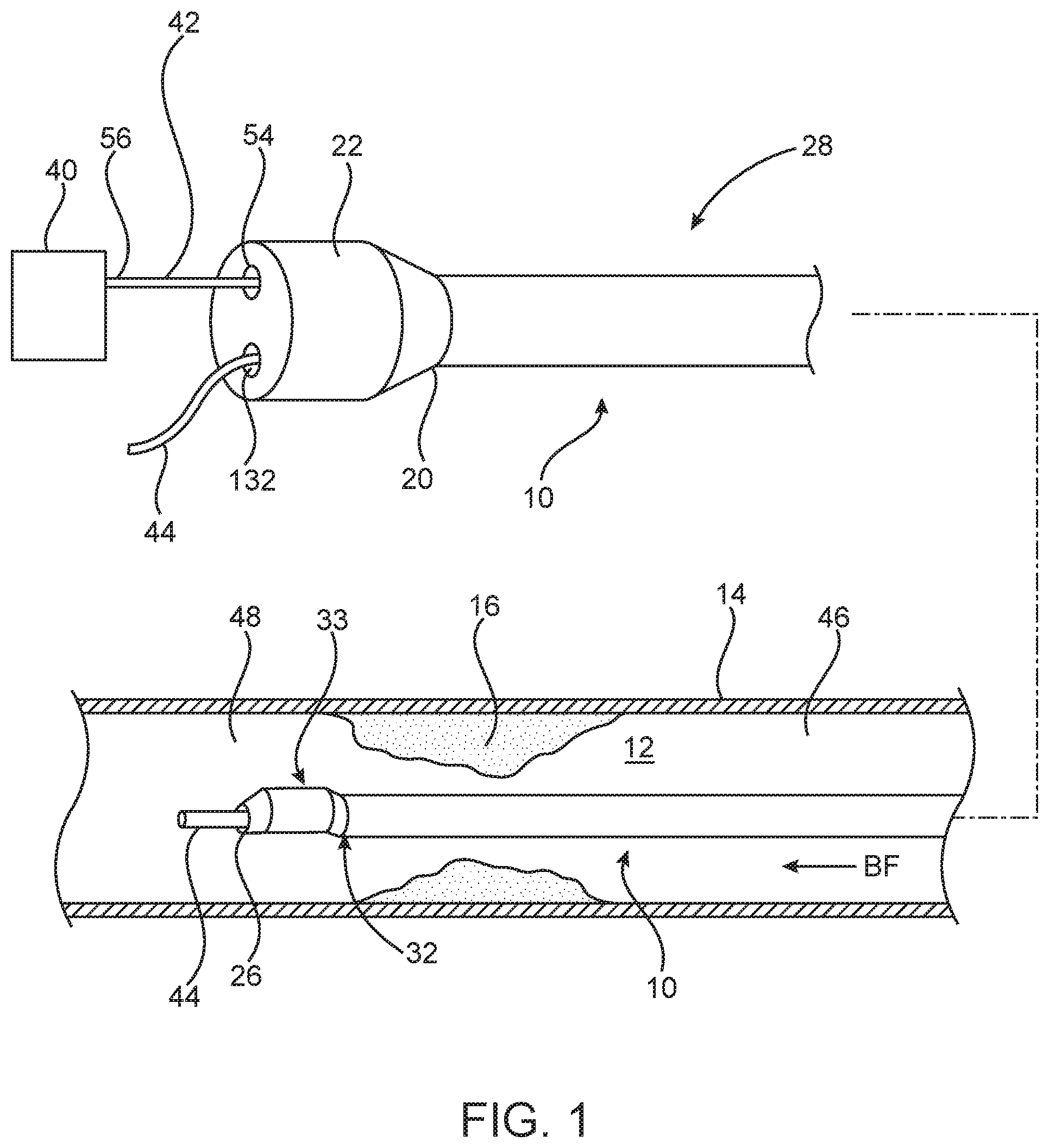
FIG. 1 is a broken view of a system for measuring FFR with a distal portion thereof shown within a vessel including a lesion, the system including a measurement catheter including a pressure sensor and a guidewire, in accordance with an embodiment hereof.
FIG. 2 is a broken view of the catheter of FIG. 1 in partial longitudinal cross-section.
FIG. 3 is a cross-sectional view of the catheter taken along line 3-3 of FIG. 2.
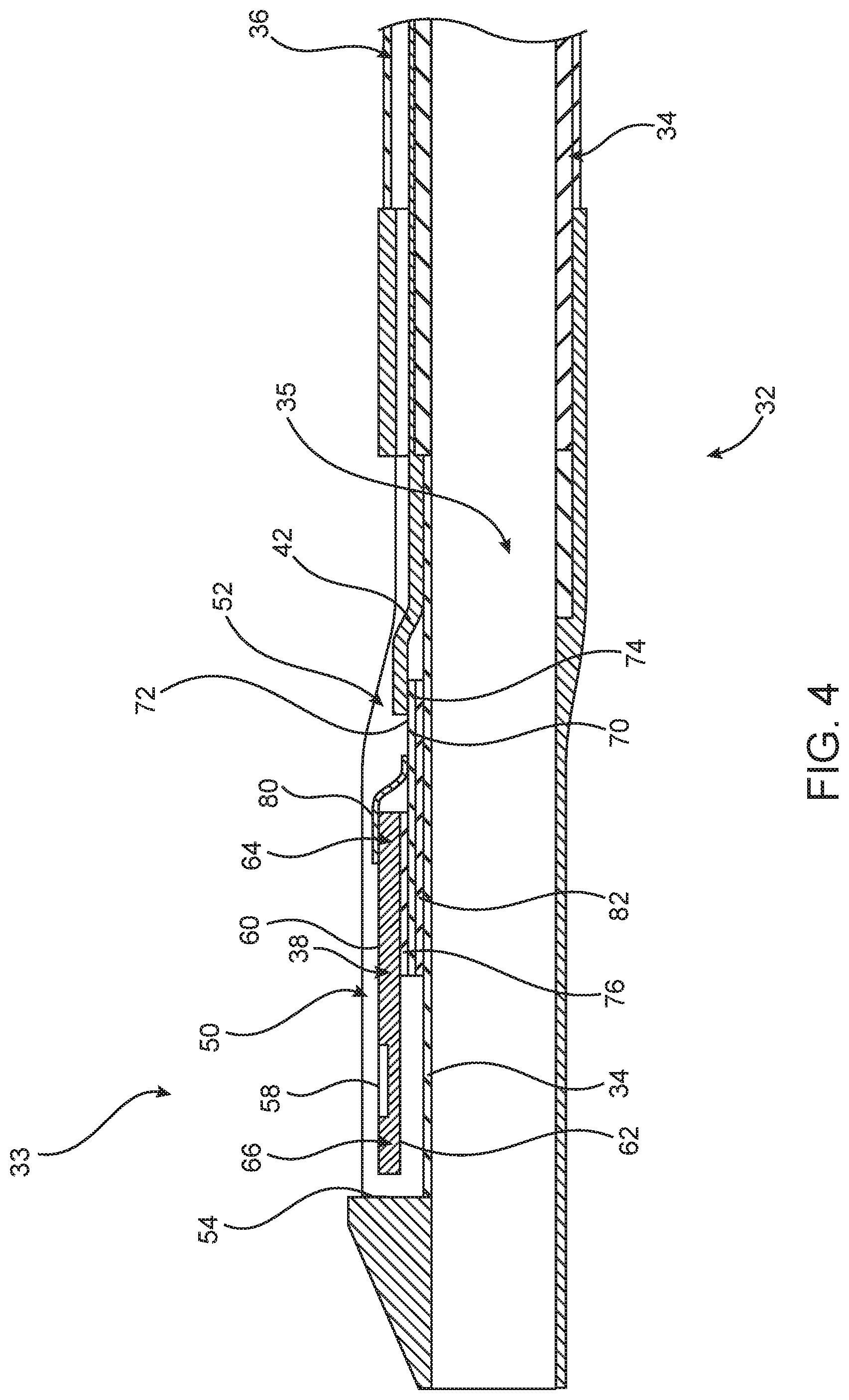
FIG. 4 is a longitudinal cross-sectional view of the distal portion of the catheter of FIG. 1.
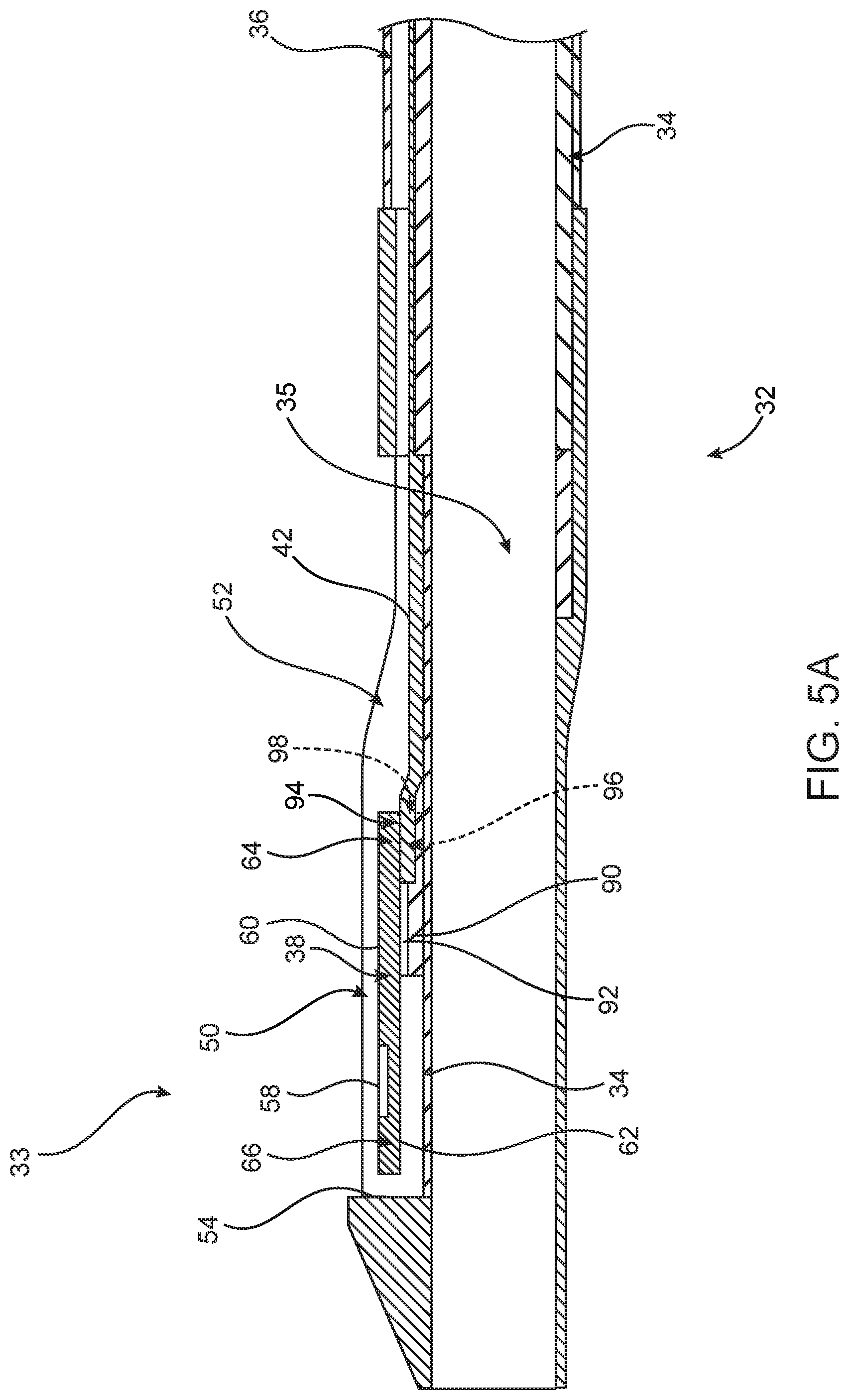
FIG. 5A is a longitudinal cross-sectional view of one example of the distal portion of the catheter of FIG. 1.
FIG. 5B is a longitudinal cross-sectional view of another example of the distal portion of the catheter of FIG. 1.
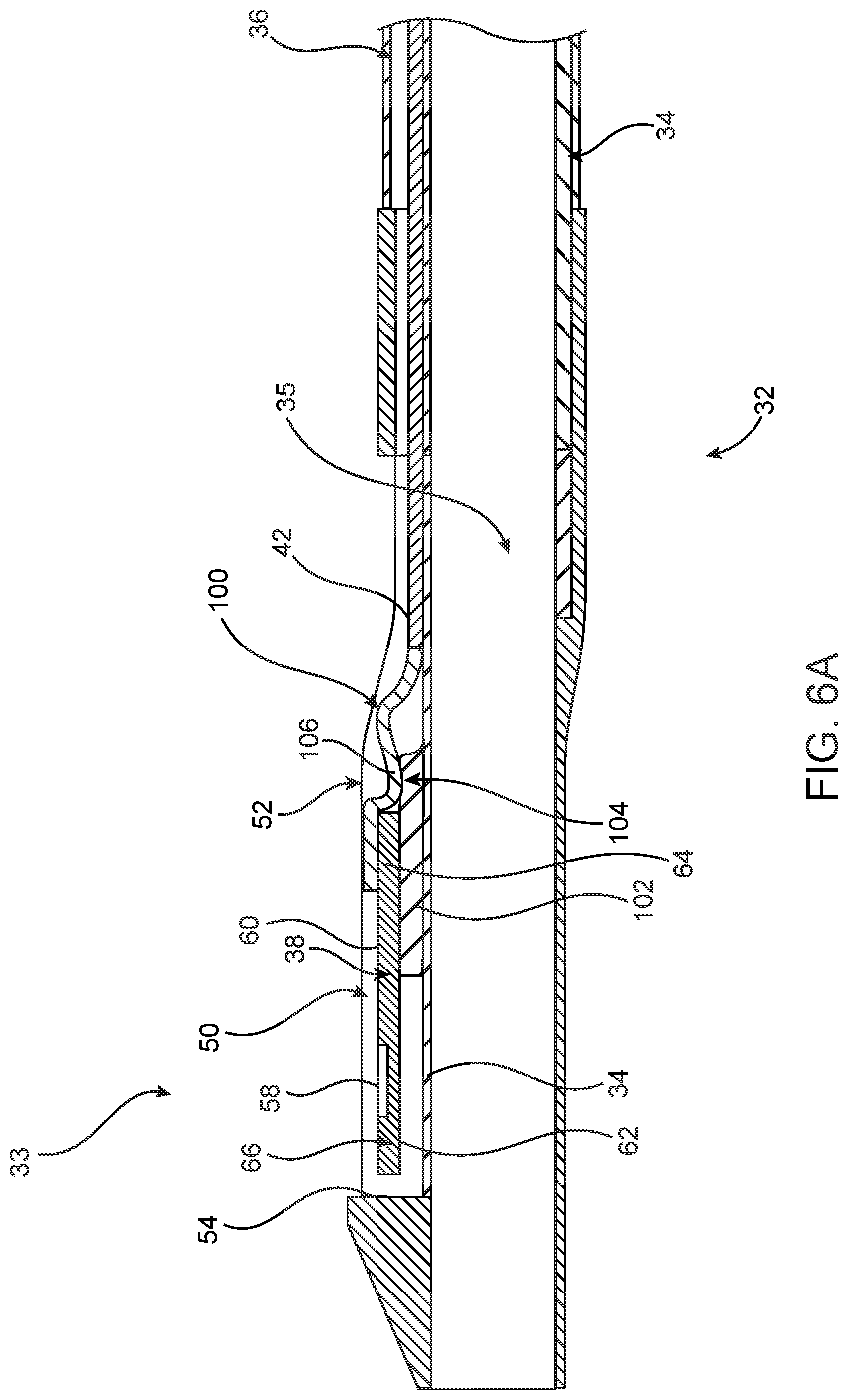
FIG. 6A is a longitudinal cross-sectional view with an interposer shown in the distal portion of the catheter of FIG. 1.
FIG. 6B is a top view of the distal portion of the catheter of FIG. 6A.
FIG. 7 is a longitudinal cross-sectional view of one example of the distal portion of the catheter of FIG. 1.
FIG. 8 is a longitudinal cross-sectional view of an optional embodiment of of the distal portion of the catheter of FIG. 1.
DETAILED DESCRIPTION OF THE INVENTION
Specific embodiments of the present invention are now described with reference to the figures, wherein like reference numbers indicate identical or functionally similar elements. While the disclosure refers to illustrative embodiments for particular applications, it should be understood that the disclosure is not limited thereto. Modifications can be made to the embodiments described herein without departing from the scope of the present disclosure. Those skilled in the art with access to this disclosure will recognize additional modifications, applications, and embodiments within the scope of this disclosure and additional fields in which the disclosed examples could be applied. Therefore, the following detailed description is not meant to be limiting. Further, it is understood that the systems and methods described below can be implemented in many different embodiments of hardware. Any actual hardware described is not meant to be limiting. The operation and behavior of the systems and methods presented are described with the understanding that modifications and variations of the embodiments are possible given the level of detail presented.
References to "one embodiment," "an embodiment," "in certain embodiments," etc., indicate that the embodiment described may include a particular feature, structure, or characteristic, but every embodiment may not necessarily include the particular feature, structure, or characteristic. Moreover, such phrases are not necessarily referring to the same embodiment. Further, when a particular feature, structure, or characteristic is described in connection with an embodiment, it is submitted that it is within the knowledge of one skilled in the art to affect such feature, structure, or characteristic in connection with other embodiments whether or not explicitly described.
Specific embodiments of the present invention are now described with reference to the figures, wherein like reference numbers indicate identical or functionally similar elements. The terms "distal" and "proximal" are used in the following description with respect to a position or direction relative to the treating clinician. "Distal" and "distally" are positions distant from or in a direction away from the clinician. "Proximal" and "proximally" are positions near or in a direction toward the clinician.
With reference to FIG. 1, a pressure measurement catheter 10 is shown with a proximal portion thereof outside of a patient and a distal portion thereof positioned in situ within a lumen 12 of a patient vessel 14 having a stenosis or lesion 16. In an embodiment hereof, the vessel 14 is a blood vessel such as but not limited to a coronary artery. Lesion 16 is generally representative of any blockage or other structural arrangement that results in a restriction to the flow of fluid through lumen 12 of vessel 14. Lesion 16 may be a result of plaque buildup, including without limitation plaque components such as fibrous, fibro-lipidic (fibro fatty), necrotic core, calcified (dense calcium), blood, fresh thrombus, and mature thrombus. Generally, the composition of lesion will depend on the type of vessel being evaluated. In that regard, it is understood that embodiments hereof are applicable to various types of blockage or other narrowing of a vessel that results in decreased fluid flow.
Measurement catheter 10 is shown in FIG. 2 with a distal portion thereof in longitudinal cross-section. Measurement catheter 10 includes an elongate shaft 18 having a proximal end 20 that may be coupled to a handle or luer fitting 22 and a distal end 24 having a distal opening 26. Elongate shaft 18 further includes a proximal portion 28, an intermediate portion 30, and a distal portion 32 having a distal tip 33. Although proximal portion 28, intermediate portion 30, and distal portion 32 of elongate shaft 18 have been described separately, they are described in such a manner for convenience and elongate shaft 18 may be constructed unitarily such that the portions described are part of a unitary shaft. However, different portions of elongate shaft 18 may also be constructed separately and joined together.
In embodiments hereof, elongate shaft 18 or component and/or segments thereof may be formed of polymeric materials, non-exhaustive examples of which include polyethylene terephthalate (PET), polypropylene, polyethylene, polyether block amide copolymer (PEBA), polyamide, fluoropolymers, and/or combinations thereof, either laminated, blended or co-extruded. Optionally, the catheter shaft or some portion thereof may be formed as a composite having a reinforcement material incorporated within a polymeric body in order to enhance strength and/or flexibility. Suitable reinforcement layers include braiding, wire mesh layers, embedded axial wires, embedded helical or circumferential wires, and the like. In one embodiment, for example, at least a proximal portion of elongate shaft 18 may be formed from a reinforced polymeric tube. In other embodiments of an elongate tubular shaft or component in accordance herewith, a proximal segment thereof may be a hypotube of a medical grade stainless steel with outer and inner tubes of a distal segment thereof being formed from any of the polymeric materials listed above.
As shown in FIGS. 2-3, elongate shaft 18 has a shaft wall 34 defining a guide wire lumen 35 extending therethrough. Guide wire lumen 35 extends through proximal portion 28, intermediate portion 30, and distal portion 32. However, instead of the over-the-wire configuration shown in FIGS. 1-3, catheter 10 may have a rapid exchange configuration wherein guide wire lumen 35 extends through distal portion 32 and intermediate portion 30, and the guidewire exits shaft 18 through a rapid exchange port (not shown) in proximal portion 28, as would be understood by those skilled in the art. In one embodiment, with reference to the cross-sectional view of FIG. 3 (taken along line 3-3 of FIG. 2), in proximal portion 28 of elongated shaft 18, shaft wall 34 defines two separate lumens, guide wire lumen 35 and a second or pressure sensor wire lumen 36, extending parallel to each other or side-by-side along proximal portion 28. Communication wires 42 are omitted in FIG. 3 for clarity. Although depicted as circular in cross-section, one or more lumen(s) of elongated shaft 18 may have any suitable cross-section including for example circular, elliptical, rectangular or crescent-shaped. As explained in more detail below, pressure sensing wire lumen 36 may extend to distal portion 32 of elongate shaft 18 to be coupled to a pressure sensor 38, as shown in FIGS. 4-5. In one embodiment, pressure sensor wire lumen 36 may be eliminated wherein a signal from pressure sensor 38 is sent to a computing device 40 other than via a wire 42 in a dedicated pressure sensor wire lumen 36, such as, but not limited to, wireless transmission or integration of wire 42 into the wall of elongate shaft 18. In other embodiments of an elongate shaft or tubular component in accordance herewith, pressure sensor wire lumen 36 may be eliminated wherein the shaft or a portion thereof may be formed by a tubular polymeric inner liner overlaid with a power lead layer and a polymeric outer jacket. In such an embodiment, the power leads for the respective pressure sensor of the inner shaft may be wrapped around the respective shaft for all or at least a portion of the shaft and secured in position by the polymeric outer jacket so as to be embedded within the shaft. In another such embodiment, the power lead for the respective pressure sensor of the inner shaft may be straight for a section or for the entire length of the shaft, and secured in position against the inner liner by the polymeric outer jacket so as to be embedded within the shaft.
Distal portion 32 of elongate shaft 18 is configured to receive a guidewire 44 in a distal portion of guidewire lumen 35 thereof. Further, as shown in FIG. 1, distal portion 32 is sized to extend from a proximal side 46 of lesion 16, through lesion 16, and to a distal side 48 of lesion 16 such that distal tip 33 is disposed on distal side 48 of lesion 16. Accordingly, in an embodiment, distal portion 32 has a length L.sub.D in the range of 25-300 mm. However, length L.sub.D may be any length suitable such that distal portion 32 may extend from proximal side 46 to distal side 48. Further, because distal portion 32 is configured to extend through lesion 16, the cross-sectional dimension or profile of distal portion 32 is minimized such as to minimize the disruption of blood flow through lesion 16 in order to obtain an accurate FFR measurement.
Distal tip 33 is disposed on distal portion 32 of elongate shaft 18. In an optional embodiment (not shown), distal tip 33 is disposed on intermediate portion 30 of elongate shaft 18 and is located proximally of distal portion 32. Distal tip 33 includes pressure sensor 38 for measuring a pressure of a fluid within lumen 12 of vessel 14, as shown in FIG. 4. In the embodiment shown in FIG. 4, pressure sensor 38 is disposed in a pocket 50 (See also FIG. 6B) of a thickened portion 52 of distal tip 33. As shown in FIG. 4, pocket 50 may be defined by at least one substantially vertical sidewall 54 and substantially horizontal shaft wall 34. In another embodiment, pocket 50 has at least one sidewall with a curvilinear shape. Pressure sensor 38 may be a piezo-resistive pressure sensor, a piezo-electric pressure sensor, a capacitive pressure sensor, an electromagnetic pressure sensor, an optical pressure sensor, and/or combinations thereof. In one non-limiting example pressure sensor 38 is a micro electromechanical sensor (MEMS) based pressure die measuring about 240 microns by 70 microns by 1100 microns in size. However, other sized pressure sensors may be used. As shown in FIG. 2, thickened portion 52 needs to accommodate pressure sensor 38. Accordingly, thickened portion 52 of elongate shaft 18 causes tip portion 33 to have an outer diameter OD.sub.1 (shown in FIG. 2) which is larger than the outer diameter OD.sub.2 of distal portion 32 of elongate shaft 18. However, depending on the size of pressure sensor 38, the outer diameters OD.sub.1 and OD.sub.2 of the elongate shaft 18 could have substantially the same diameter. In one embodiment, outer diameter OD.sub.1 of tip portion 33 is in the range of 0.024 inch-0.040 inch in order to accommodate pressure sensor 38. However, outer diameter OD.sub.1 may vary depending on the size of pressure sensor 38, thickness of elongate shaft 18, and other factors used to determine the diameter or profile of shafts. In an optional embodiment, a cover (not shown) could extend substantially over pocket 50 to protect pressure sensor 38 from contacting the vessel wall while still allowing blood to surround pressure sensor 38.
Pocket 50 is in communication with pressure sensor wire lumen 36 such that any communication wire(s) 42 from pressure sensor 38 may extend from pocket 50 proximally through pressure sensor wire lumen 36, through a corresponding lumen in luer fitting 22 exiting through proximal port 54 to a computing device 40 coupled to proximal end 56 of communication wire 42. Proximal end 56 of communication wire 42 may be coupled to computing device 40 via various communication pathways, including but not limited to one or more physical connections including electrical, optical, and/or fluid connections, a wireless connection, and/or combinations thereof. Accordingly, it is understood that additional components (e.g., cables, connectors, antennas, routers, switches, etc.) not illustrated in FIG. 1 may be included to facilitate communication between the proximal end 56 of communication wire 42 and computing device 40. In an optional embodiment, computing device 40 is incorporated into catheter 10 or for example, in proximal portion 28.
FIG. 4 is a longitudinal cross-sectional view of distal shaft portion 32 including distal tip 33. Therein, sensor 38 has a first outwardly facing surface 60, a second inwardly facing surface 62, a first distal end 64 and a second proximal end 66. A diaphragm 58 of sensor 38 is disposed on first surface 60. Communication wires 42 (for example, 0.0025 inch coated copper wire in a tri-filar configuration) extending from lumen 36 are coupled to an electrical interface, such as an interposer 70 which has first and second surfaces 72, 74. In this embodiment, communication wires form an "S-shape", such that one end of the communication wires 42 is raised up to the elevated level of first surface 72 of interposer 70. Second sensor surface 62 is coupled to first surface 72 of interposer 70 (for example, by an adhesive 76), thereby disposing interposer between shaft wall 34 of elongate shaft 18 and sensor 38.
Sensor wires 80 (for example, 0.001 inch thick gold wires) have a first end coupled to first surface 72 of interposer 70 and a second end coupled to electrical pads or metallization on first surface 60 of sensor 38. Similarly to the communication wires, sensor wires may also make an S-shape, such that one end of the sensor wires 80 is raised up to the elevated level of first surface 60 of sensor 38. Interposer 70 has second surface 74 coupled to shaft wall 34 of elongate shaft 18. In one embodiment, interposer 70 is coupled to shaft wall 34 by an adhesive 82 having a thickness of about 25 microns. Sensor 38 may be elevated above shaft wall 34 by the thickness of interposer 70 and to some degree by the thickness of the adhesive layers 76 and 82.
FIG. 5A is a longitudinal cross-sectional view of another example of distal shaft portion 32 including distal tip 33. In FIG. 5A, sensor 38 is elevated above shaft wall 34 by a step 90 extending from shaft wall 34. Sensor 38 is coupled to step 90 by, for example, an adhesive layer 92. Sensor 38 may be elevated above shaft wall 34 by a distance of about 40-50 microns. In another example, the distance between the sensor 38 and shaft wall 34 is about 25-60 microns. Sensor 38 can be coupled to step 90 at any point along the length of sensor 38. As shown in FIG. 5A, sensor 38 is coupled to step 90 at a location that is adjacent first end 64 of sensor 38. Placement of sensor 38 at this location creates an overhang 94, such that first end 64 of sensor 38 is spaced apart from shaft wall 34 thereby forming a pocket 96 under first end 64 of sensor 38. Thus, pocket 96 is defined by step 90, overhang 94 and shaft wall 34. In one example, pocket 96 could be further defined by side walls (not shown) extending from shaft wall 34 on either side of pocket 96, the side walls further extending between step 90 and overhang 94. In an optional example, step 90 extends substantially along the entire second surface 62 (except for overhang 94) of sensor 38 such that second end 62 of sensor is not suspended above shaft wall 34.
In the example of FIG. 5A, pocket 96 has an opening 98 for receiving communication wire 42 (or any type of electrical coupling such as wiring or an interposer) whereby communication wire 42 is coupled to second surface 62 of sensor 38. In this case, sensor 38 could be configured (such as by the flip chip or controlled collapse chip connection method) to have electrical pads, solder bumps or other metallization on second surface 62 instead of first surface 60, in order to provide an electrical coupling between sensor 38 and communication wire 42. Although, communication wire 42 is shown, other wires such as sensor wire 80 are also receivable within pocket 96. Thus, by directly coupling communication wire 42 to second surface 62 of sensor 38 within pocket 96, the example of FIG. 5A (as compared with FIG. 4) has eliminated interposer 70, adhesive layers 76 and 82, and any additional wiring, such as sensor wire 80. By eliminating components needed to create an electrical coupling, the profile of thickened portion 52 is reduced or minimized.
FIG. 5B is a longitudinal cross-sectional view of another example of distal shaft portion 32 including distal tip 33. In this example, sensor 38 is similar to the sensor of FIG. 4 with the electrical pads or other metallization, and diaphragm 58 both disposed on first surface 60 of sensor 38. However, in the example of FIG. 5B, sensor 38 is "flipped" or mounted upside down onto step 90. In this configuration, communication wire 42 is receivable within pocket 96 and coupled to first surface 60 of sensor 38.
FIG. 6A is a longitudinal cross-sectional view of another example of distal shaft portion 32 including distal tip 33. In addition to reducing the profile of distal tip 33 to a minimum, isolating sensor 38 from any stress or strain is important because physical or mechanical distortion of sensor 38 can result in an incorrect pressure reading. One source of stress or strain applied to sensor 38 could be from the movement of electrical leads, pressure sensor wire 80, or communication wire 42 during operation of catheter 10. To avoid stress and strain from such wiring, one option is to couple one end of a flexible interconnect 100 to communication wire 42 and to couple the other end of flexible interconnect 100 to first surface 60 of sensor 38, as shown in FIG. 6A. Flexible interconnect 100 can be manufactured with cross-sectional profiles as low as 25 microns further reducing the profile of distal tip 33. In one example, sensor 38 is mounted and positioned on one portion of step 102 (which extends from shaft wall 34) in such a way as to form a ledge 104 having a top surface 106. Flexible interconnect 100 can lie against ledge 104 as well as move or slidably curve across top surface 106 of ledge 104 in response to bending forces. Flexible interconnect 100 has elastic and deformable properties that allow flexible interconnect 100 to move, bend and adjust within distal tip 33. The resilient characteristics of flexible interconnect 100 not only help flexible interconnect 100 to minimize the profile of distal tip 33 but also the stress and strain acting on distal tip 33 are absorbed by flexible interconnect 100, instead of sensor 38, further isolating sensor 38 from these bending forces. In addition, flexible interconnect 100 allows sensor 38 and communication wire 42 to move independently from one another, further alleviating the stress and strain being applied to sensor 38.
FIG. 6B is a top view of the embodiment illustrated in FIG. 6A showing flexible interconnect 100 in a curved and compacted configuration to minimize profile of distal tip 33. As can be seen in FIG. 6B, electrical wiring 108 (disposed on or within flexible interconnect 100) couples communication wire 42 to electrical pads 110 of sensor 38. Not only does flexible interconnect 100 minimize the profile of distal tip 33, flexible interconnect 100 also provides a much more stable coupling than, for example, three separate wires coupling communication wire 42 with sensor 38. In addition, separate wiring would require epoxy or solder at each joint to secure wiring to sensor 38, thereby adding to the profile of distal tip 33.
FIG. 7 is a longitudinal cross-sectional view of another example of distal shaft portion 32 including distal tip 33. In the example of FIG. 7, distal tip 33 does not have an interposer or sensor wires. Instead, a gap 120 is provided between sensor 38 and communication wire 42. A top surface 122 of shaft wall 34 which spans the distance of gap 120 is metallized, or electrical leads are etched into top surface 122. As a result, communication wire 42, which is in contact with top surface 122, is electrically coupled to top surface 122 of shaft wall 34. One way to metalize top surface 122 of shaft wall is to mold distal tip 33 with an appropriately doped polymer. Portions of the polymer are exposed to laser direct structuring technology to activate the polymer for selective plating as well as to create patterns for electrical pad configurations. Once the mold is complete, layers of metallization (typically 5-8 microns thick) are placed into the electrical pad patterns thereby electrically coupling sensor 38 with communication wire 42. In an optional example, metallization or electrical leads can be integrated within shaft wall 34 and do not need to extend along top surface 122 of shaft wall 34.
By spanning the distance between sensor 38 and communication wire 42, gap 120 provides a flex region disposed between sensor 38 and communication wire 42. The flex region bends or twists in response to the catheter's movement in the patient's vasculature, which absorbs stress and strain forces that would otherwise be transmitted to sensor 38. The flex region also allows sensor 38 and communication wire 42 to move independently from one another further reducing the amount of stress and strain forces being transmitted to sensor 38. As shown in FIG. 7, a bonding member 124, such as a gold wire bond, is coupled between sensor 38 and top surface 122 of shaft wall 34. More specifically, bonding member 124 has one end 126 coupled to electrical pads 110 of sensor 38, and bonding member 124 has another end 128 coupled to top surface 122 of shaft wall 34. Thus, bonding member 124 provides a bridge to electrically couple sensor 38 to communication wire 42 through top surface 122 of shaft wall 34.
FIG. 8 is a longitudinal cross-sectional view of an optional embodiment of distal shaft portion 32 having a protective covering or cap 150 disposed about and partially or fully enclosing distal tip 33. Although cap 150 could partially or fully enclose an embodiment of any distal tip disclosed herein, cap 150 of FIG. 8 is shown disposed about distal tip 33 of FIG. 5B. With diaphragm 58 facing inward toward surface 34 instead of being exposed directly to fluid in lumen 12, distal tip 33 would need at least one opening 160 in cap 110, preferably, in close proximity to diaphragm 58 to allow ingress of fluid for pressure measurement. In one example, opening 160 would be disposed on the side portion cap 150 (as shown in FIG. 8) such that the opening 160 would be close enough to sensor 38 and diaphragm 58 to provide fluid communication between sensor 38, diaphragm 58 and lumen 12 of patient vessel 14 thereby allowing a pressure measurement by sensor 38. Opening 160 can be positioned anywhere on cap 160 and opening 160 can be of any shape or size depending on the desired amount of fluid communication between patient vessel 14 and sensor 38.
A method of measuring FFR using measurement catheter 10 will now be described with reference to FIG. 1. As would be understood by those skilled in the art, when measuring FFR a guide catheter (not shown) may be advanced through the vasculature such that the guide catheter is disposed within the aorta with a distal end thereof disposed within the aorta at an ostium of the aorta adjacent the branch vessel 14 within which lesion 16 is located. As shown in FIG. 1, guidewire 44 can be advanced intraluminally through the guide catheter, into vessel 14 within lumen 12 to the site of lesion 16. In the embodiment shown, guidewire 44 is advanced from proximal side 46 of lesion 16 to distal side 48 of lesion 16, which is also consistent with the direction of the blood flow BF, as indicated by the arrow BF in FIG. 1. In an embodiment, vessel 14 is a coronary artery, but vessel 14 may be other vessels in which it may be desirable to measure pressure, and in particular, to measure FFR.
Thereafter, as shown in FIG. 1, measurement catheter 10 can be tracked or advanced over indwelling guidewire 44 to the target site such that distal end 32 of elongate shaft 18 is positioned distal of lesion 48. As can be seen in FIG. 1, distal tip 33 including pressure sensor 33 can be disposed distally of lesion 16 such that elongate shaft 18 is disposed through lesion 16.
With measurement catheter 10 in place, pressure sensor 33 measures the pressure of blood distal of the lesion within lumen 12. Accordingly, the pressure measured by pressure sensor 33 is the distal pressure measurement, or P.sub.d, used in calculating FFR. In one embodiment, adenosine is administered either intracoronary at the site, bolus, or intravenously by continuous infusion for providing an accurate distal pressure measurement (P.sub.d) for an FFR value. A proximal pressure measurement P.sub.a, which is taken in the aorta by an external AO pressure transducer associated with the guide catheter, and a simultaneous pressure measurement P.sub.d taken with pressure sensor 33 of measurement catheter 10 are then obtained to provide the FFR value, i.e., P.sub.d/P.sub.a, for the lesion. The proximal pressure measurement P.sub.a and distal pressure measurement P.sub.d can be communicated to computing device 40. Computing device 40, shown schematically in FIGS. 1 and 2, may include such components as a CPU, a display device, an amplification and filtering device, an analog-to-digital converter, and various other components. Computing device 40 may receive the proximal pressure measurement P.sub.a and distal pressure measurement P.sub.d, and may process them to provide a continuous display of FFR measurement.
When the FFR measurement is completed, measurement catheter 10 may then be completely withdrawn from the patient or repositioned in vivo at another lesion and the process repeated. Pressure-sensing catheters in accordance with embodiments hereof may be used for other than providing proximal and distal pressure measurements (P.sub.a, P.sub.d) for calculating an FFR value. For instance, pressure-sensing catheters in accordance with embodiments hereof may be used to provide an in vivo pressure measurement anywhere along the vasculature, or a particular lesion therein. As well, embodiments hereof may be used to provide in vivo pressure measurements, across a heart valve, venous valve or other valvular location within the body where it may be deemed useful.
The detailed description is merely exemplary in nature and is not intended to limit the invention or the application and uses of the invention. Although the description of the invention is in the context of treatment of blood vessels such as the coronary arteries, the invention may also be used in any other body passageways where it is deemed useful such as but not limited to peripheral arteries, carotid arteries, renal arteries, and/or venous applications. Furthermore, there is no intention to be bound by any expressed or implied theory presented in the preceding technical field, background, brief summary or the detailed description.
While various embodiments according to the present invention have been described above, it should be understood that they have been presented by way of illustration and example only, and not limitation. It will be apparent to persons skilled in the relevant art that various changes in form and detail can be made therein without departing from the scope of the invention. Thus, the breadth and scope of the present invention should not be limited by any of the above-described exemplary embodiments. It will also be understood that each feature of each embodiment discussed herein, and of each reference cited herein, can be used in combination with the features of any other embodiment.
* * * * *
D00000
D00001
D00002
D00003
D00004
D00005
D00006
D00007
D00008
D00009
D00010
XML
uspto.report is an independent third-party trademark research tool that is not affiliated, endorsed, or sponsored by the United States Patent and Trademark Office (USPTO) or any other governmental organization. The information provided by uspto.report is based on publicly available data at the time of writing and is intended for informational purposes only.
While we strive to provide accurate and up-to-date information, we do not guarantee the accuracy, completeness, reliability, or suitability of the information displayed on this site. The use of this site is at your own risk. Any reliance you place on such information is therefore strictly at your own risk.
All official trademark data, including owner information, should be verified by visiting the official USPTO website at www.uspto.gov. This site is not intended to replace professional legal advice and should not be used as a substitute for consulting with a legal professional who is knowledgeable about trademark law.