Linear vibration motor
Zhu , et al. April 6, 2
U.S. patent number 10,971,983 [Application Number 16/083,934] was granted by the patent office on 2021-04-06 for linear vibration motor. This patent grant is currently assigned to GOERTEK INC.. The grantee listed for this patent is GOERTEK INC.. Invention is credited to Baoyu Liu, Dezhang Shi, Yueguang Zhu.


| United States Patent | 10,971,983 |
| Zhu , et al. | April 6, 2021 |
Linear vibration motor
Abstract
The present invention relates to the technical field of electronic products, and provides a linear vibration motor. The linear vibration motor comprises a motor housing, a stator, a vibrator, and two elastic supports for suspending the vibrator within the motor housing, for supporting the vibrator and for providing elastic restoring forces, wherein the elastic supports are located at two ends of the vibrator in a vibration direction respectively. Each of the elastic supports is made up of a plurality of elastic sheets whose one ends are fixedly connected in sequence, which are arranged side by side and which have C-shaped openings respectively. Each of the elastic supports comprises a first connection point fixedly connected to the vibrator and a second connection point fixedly connected to the inner wall of the motor housing. Therefore, the polarization phenomenon of a vibration block is reduced when the vibration feedback to a user's touch operation is realized, the noise is reduced, and the stability and the reliability of the entire linear vibration motor are improved.
| Inventors: | Zhu; Yueguang (Weifang, CN), Liu; Baoyu (Weifang, CN), Shi; Dezhang (Weifang, CN) | ||||||||||
|---|---|---|---|---|---|---|---|---|---|---|---|
| Applicant: |
|
||||||||||
| Assignee: | GOERTEK INC. (Weifang,
CN) |
||||||||||
| Family ID: | 1000005471694 | ||||||||||
| Appl. No.: | 16/083,934 | ||||||||||
| Filed: | June 1, 2016 | ||||||||||
| PCT Filed: | June 01, 2016 | ||||||||||
| PCT No.: | PCT/CN2016/084293 | ||||||||||
| 371(c)(1),(2),(4) Date: | September 11, 2018 | ||||||||||
| PCT Pub. No.: | WO2017/152516 | ||||||||||
| PCT Pub. Date: | September 14, 2017 |
Prior Publication Data
| Document Identifier | Publication Date | |
|---|---|---|
| US 20200295646 A1 | Sep 17, 2020 | |
Foreign Application Priority Data
| Mar 11, 2016 [CN] | 201610140464.1 | |||
| Current U.S. Class: | 1/1 |
| Current CPC Class: | H02K 33/02 (20130101); H02K 5/24 (20130101) |
| Current International Class: | H02K 33/02 (20060101); H02K 5/24 (20060101) |
| Field of Search: | ;310/29 |
References Cited [Referenced By]
U.S. Patent Documents
| 8384259 | February 2013 | Choi |
| 8643229 | February 2014 | Park |
| 8682396 | March 2014 | Yang |
| 10468957 | November 2019 | Zhu |
| 2011/0089772 | April 2011 | Dong |
| 2011/0101798 | May 2011 | Lee |
| 2011/0266892 | November 2011 | Wauke |
| 2016/0013710 | January 2016 | Dong |
| 2019/0036435 | January 2019 | Zhu |
| 2019/0081544 | March 2019 | Zhu |
| 2019/0222106 | July 2019 | Liu |
| 103098357 | May 2013 | CN | |||
| 103618428 | Mar 2014 | CN | |||
| 103762815 | Apr 2014 | CN | |||
| 105226909 | Jan 2016 | CN | |||
| 204947873 | Jan 2016 | CN | |||
| 205004932 | Jan 2016 | CN | |||
| 105656274 | Jun 2016 | CN | |||
| 2004104906 | Apr 2004 | JP | |||
Attorney, Agent or Firm: Saliwanchik, Lloyd & Eisenschenk
Claims
The invention claimed is:
1. A linear vibration motor, comprising a motor housing, a stator, a vibrator, and two elastic supports for suspending the vibrator within the motor housing, for supporting the vibrator and for providing elastic restoring forces, wherein the two elastic supports are located at two ends of the vibrator in a vibration direction thereof respectively; each of the elastic supports is made up of a plurality of elastic sheets whose one ends are fixedly connected in sequence, which are arranged side by side and which have C-shaped openings respectively; each of the elastic supports comprises a first connection point and a second connection point, wherein the first connection point is fixedly connected to an end surface of the vibrator perpendicular to the vibration direction of the vibrator, and the second connection point is fixedly connected to an inner wall of the motor housing perpendicular to the vibration direction of the vibrator, wherein the C-shaped openings of the plurality of elastic sheets are open in a direction perpendicular to the vibration direction of the vibrator, and wherein the plurality of elastic sheets are fixedly connected in a form of forward welding, and are thus arranged to be overlapped when viewed from the vibration direction of the vibrator.
2. The linear vibration motor according to claim 1, wherein the C-shaped openings of the plurality of elastic sheets all face the same direction.
3. The linear vibration motor according to claim 1, wherein the C-shaped openings of neighboring elastic sheets of each elastic support face opposite directions.
4. The linear vibration motor according to claim 1, wherein the first connection points of the elastic supports arranged at two ends of the vibrator are diagonally arranged in a region defined by the motor housing.
5. The linear vibration motor according to claim 1, wherein the vibrator comprises a mass block and magnets, and the mass block is provided with mounting holes allowing the magnets to be mounted therein.
6. The linear vibration motor according to claim 5, wherein the first connection points of the two elastic supports are respectively arranged on sidewalls on two sides of the mass block, and are disposed oppositely from each other, in the vibration direction, about a center of the mass block.
7. The linear vibration motor according to claim 5, wherein a stop block is arranged at a position where the first connection point and the sidewall of the mass block are connected and a position where the second connection point and the inner wall of the motor housing are connected, respectively.
8. The linear vibration motor according to claim 7, wherein a damping block is arranged on the stop blocks respectively; and a make-way mechanism for increasing a damping area of the damping block is arranged on each stop block.
9. The linear vibration motor according to claim 1, wherein the stator comprises a circuit board which is fixed to a lower portion of the motor housing and connected to a coil.
10. The linear vibration motor according to claim 1, wherein the motor housing comprises an upper housing and a lower housing.
Description
CROSS REFERENCE TO RELATED APPLICATIONS
This application is a National Stage of International Application No. PCT/CN2016/084293, filed on Jun. 1, 2016, which claims priority to Chinese Patent Application No. 201610140464.1, filed on Mar. 11, 2016, both of which are hereby incorporated by reference in their entireties.
TECHNICAL FIELD
The present invention relates to the technical field of electronic products, and in particular, to a linear vibration motor.
BACKGROUND
At present, with the rapid development of portable consumer electronics, consumers are increasingly favoring electronic products that are more lighter and thinner and have a better tactile experience. The linear vibration motor is generally used as an execution mechanism for tactile experience and functions for system vibration feedback. The development trend of thinner and lighter electronic products determines that elastic supports must also be improved towards a flat profile.
Linear vibration motors mostly achieve overall vibration through elastic supports. The elastic supports are mostly springs or elastic sheets. The elastic supports in the form of the springs or the elastic sheets are mainly designed based on a space inside each linear vibration motor, and are different in shape and connection manner respectively. However, the design structures of the elastic supports commonly available on the market are unreasonable, which results in that the elastic supports easily cause stress concentration during the vibration process, resulting in plastic deformation, polarization, and relatively large noise, thereby affecting the user experience and use.
SUMMARY
An objective of the present invention is to provide a linear vibration motor that aims to solve the problem that the design structure of an elastic support in the prior art is unreasonable, which results in that the elastic support easily causes stress concentration during the vibration process, resulting in plastic deformation, polarization, and relatively large noise, thereby affecting the user experience and use.
The present invention is implemented as below. A linear vibration motor comprises a motor housing, a stator, a vibrator, and two elastic supports for suspending the vibrator within the motor housing, for supporting the vibrator and for providing elastic restoring forces. The two elastic supports are located at two ends of the vibrator in a vibration direction.
Each of the elastic supports is made up of a plurality of elastic sheets whose one ends are fixedly connected in sequence, which are arranged side by side and which have C-shaped openings respectively. Each of the elastic supports comprises a first connection point fixedly connected to the vibrator and a second connection point fixedly connected to the inner wall of the motor housing.
As an improved solution, the C-shaped openings of the plurality of elastic sheets all face the same direction.
As an improved solution, the C-shaped openings of the adjacent elastic sheets of each elastic support face opposite directions.
As an improved solution, the first connection points of the elastic supports arranged at two ends of the vibrator are diagonally arranged in a region defined by the motor housing.
As an improved solution, the vibrator comprises a mass block and magnets, wherein the mass block is provided with mounting holes allowing the magnets to be mounted therein.
As an improved solution, the first connection points of the two elastic supports are arranged in the center of each of the sidewalls on two sides of the mass block in the vibration direction respectively.
As an improved solution, a stop block is arranged at a position where the first connection point and the sidewall of the mass block are connected and a position where the second connection point and the inner wall of the motor housing are connected, respectively.
As an improved solution, a damping block is arranged on the stop blocks respectively;
a make-way mechanism for increasing a damping area of the damping block is arranged on each stop block.
As an improved solution, the stator comprises a circuit board which is fixed to the inner wall of the motor housing and connected to a coil.
As an improved solution, the motor housing comprises an upper housing and a lower housing.
The linear vibration motor comprises the motor housing, the stator, the vibrator, and two elastic supports for suspending the vibrator within the motor housing, for supporting the vibrator and for providing elastic restoring forces. The two elastic supports are located at two ends of the vibrator in a vibration direction. Each of the elastic supports is made up of a plurality of elastic sheets whose one ends are fixedly connected in sequence, which are arranged side by side and which have C-shaped openings respectively. Each of the elastic supports comprises a first connection point fixedly connected to the vibrator and a second connection point fixedly connected to the inner wall of the motor housing. Therefore, the polarization phenomenon of a vibration block in a vibration process is reduced when the vibration feedback to a user's touch operation is realized, the noise is reduced, and the stability and the reliability of the entire linear vibration motor are improved.
BRIEF DESCRIPTION OF THE DRAWINGS
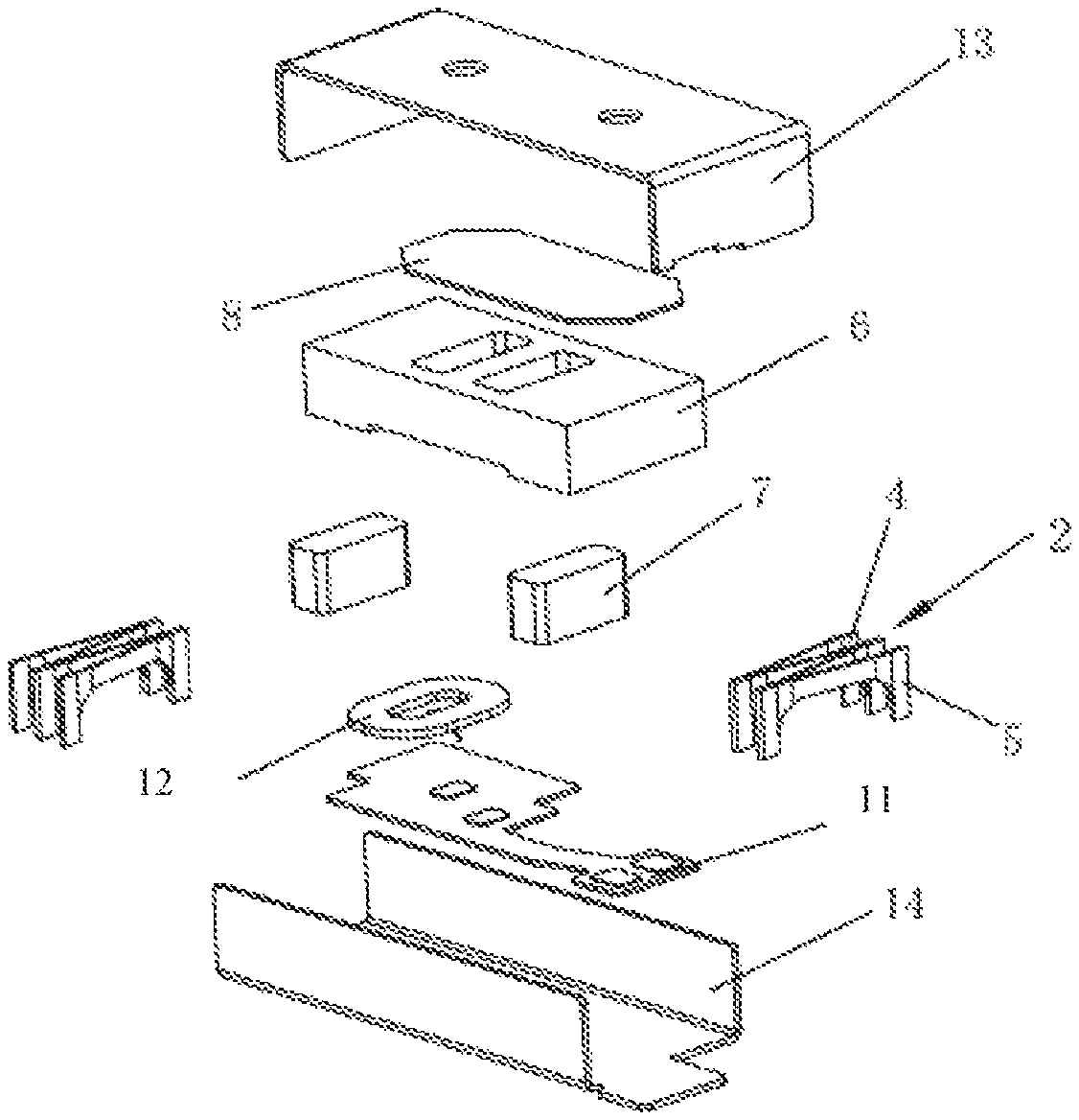
FIG. 1 is an exploded schematic view of a linear vibration motor provided by Embodiment 1 of the present invention;
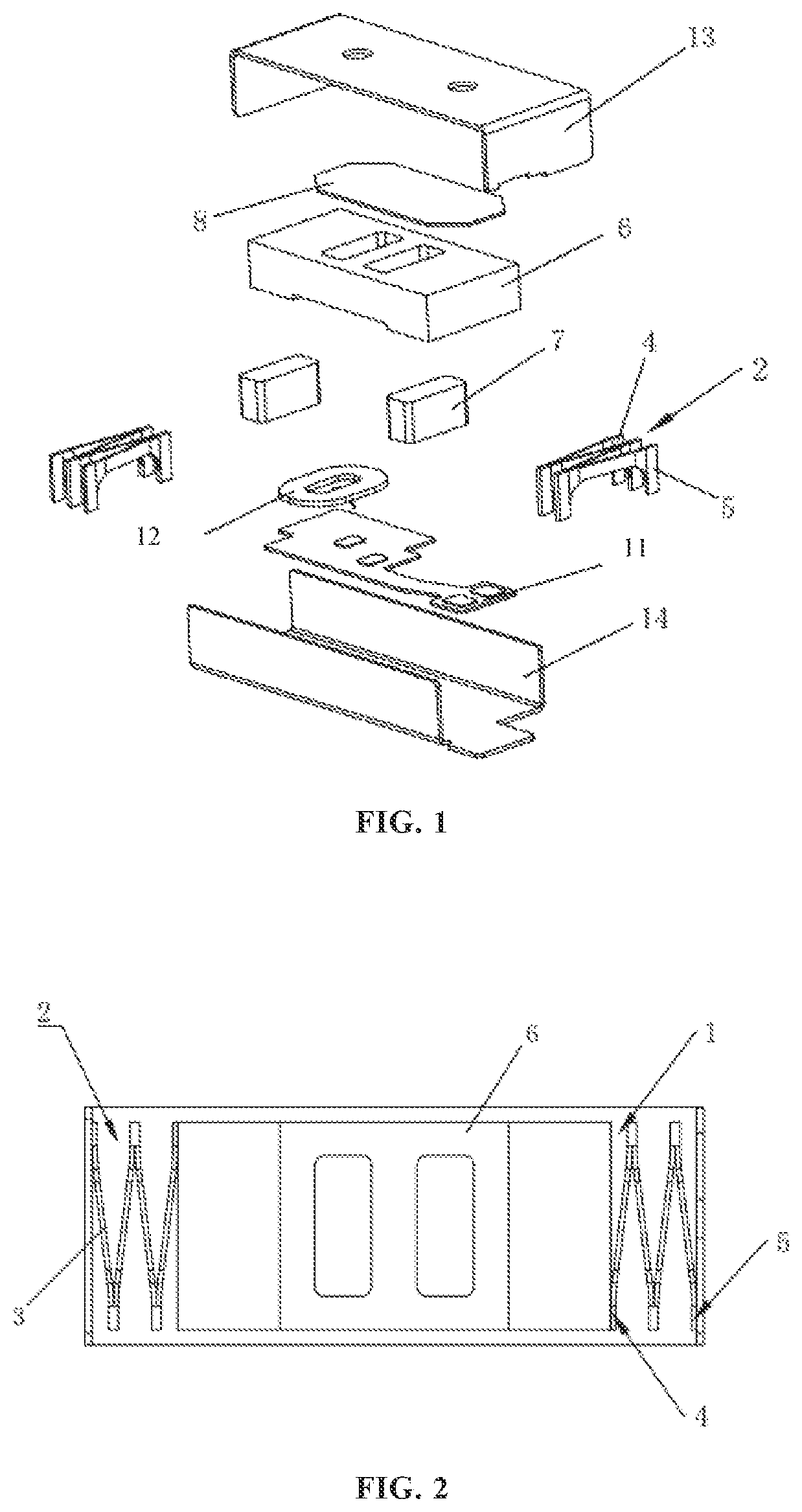
FIG. 2 is a top view of FIG. 1;
FIG. 3 is a schematic structural view of an elastic support provided by Embodiment 1 of the present invention;
FIG. 4 is an exploded schematic view of a linear vibration motor provided by Embodiment 2 of the present invention;
FIG. 5 is a top view of FIG. 4;
FIG. 6 is a schematic structural view of an elastic support provided by Embodiment 2 of the present invention;
FIG. 7 is a schematic structural view of an elastic sheet provided by the present invention;
the reference signs represent the following components: 1--vibrator; 2--elastic support; 3--elastic sheet; 4--first connection point; 5--second connection point; 6--mass block; 7--magnet; 8--washer plate; 9--stop block; 10--damping block; 11--circuit board; 12--coil; 13--upper housing; 14--lower housing.
DETAILED DESCRIPTION
In order to make the objective, the technical solution and the advantages of the present invention more clearly, the present invention is further illustrated in details below in conjunction with the drawings and the embodiments. It should be understood that, the specific embodiments described herein are merely used to illustrate the present invention rather than limit the present invention.
FIG. 1 and FIG. 2 illustrate an exploded schematic view of a linear vibration motor provided by the present invention respectively, in which only parts relevant to the present invention are shown for ease of illustration.
As shown in FIGS. 3 to 7, the linear vibration motor comprises a motor housing, a stator, a vibrator 1, and two elastic supports 2 for suspending the vibrator 1 within the motor housing, for supporting the vibrator 1 and for providing elastic restoring forces. The two elastic supports 2 are located at two ends of the vibrator 1 in a vibration direction respectively.
Each of the elastic supports 2 is made up of a plurality of elastic sheets 3 whose one ends are fixedly connected in sequence, which are arranged side by side and which have C-shaped openings respectively. Each of the elastic supports 2 comprises a first connection point 4 fixedly connected to the vibrator 1 and a second connection point 5 fixedly connected to the inner wall of the motor housing.
In the present embodiment, as shown in FIG. 7, the elastic sheets 3 may be slightly bent according to an actual space of a product, and will not be described here.
The plurality of elastic sheets 3 may be fixedly connected in a form of forward welding. By means of this connection manner, the space of the elastic supports 2 in the vibration direction of the vibrator 1 is saved, and meanwhile the rigidity of the elastic sheets 3 in the vibration direction is effectively reduced, such that the compliance of the elastic sheets 3 in the vibration direction is larger to effectively reduce the inherent frequency of the entire linear vibration motor. In the meantime, in the case of the same driving force, a larger displacement is obtained in the vibration direction, and a higher vibration sense can be achieved.
In the meantime, the elastic sheets 3 welded forwardly together may share the stress of each elastic sheet 3, thereby effectively reducing the phenomenon of stress concentration. By means of a flat structure, the occupied space after compression is smaller, the vibration stability is higher, the vibration offset is smaller, and the reliability and the service life of the product are greatly improved and prolonged.
As shown in FIGS. 1 to 3, the C-shaped openings of the plurality of elastic sheets 3 face the same direction, i.e., the plurality of elastic sheets 3 is connected together side by side according to the direction of the C-shaped openings to form the corresponding elastic support 2.
As shown in FIGS. 4 to 6, the C-shaped openings of the adjacent elastic sheets 3 of each elastic support 2 face opposite directions, i.e., the plurality of elastic sheets 3 every two of which face opposite directions and are connected together side by side form the elastic support 2 according to the directions of the C-shaped openings.
As shown in FIG. 7, each elastic sheet 3 has a structure of a C-shaped opening. The number of the elastic sheets 3 in each elastic support 2 may be set according to actual demands. The case of four elastic sheets 3 is given in FIGS. 1 to 6. Of course, other numbers, i.e., at least two elastic sheets are also available.
In the present invention, the vibrator 1 comprises a mass block 6 and magnets 7 except for the elastic supports 2 described above. As shown in FIG. 1 and FIG. 4, the mass block 6 is provided with mounting holes allowing the magnets 7 to be mounted therein. The magnets 7 may be mounted by adopting a washer plate 8. Of course, other manners may also be adopted.
A position where the first connection point 4 of each elastic support 2 and the mass block 6 are connected and a position where the second connection point 5 of each elastic support 2 and the inner wall of the motor housing are connected may be set according to actual situations, e.g., according to the following two manners.
(1) The first connection points 4 of the elastic supports 2 arranged at two ends of the vibrator 1 are diagonally arranged in a region defined by the motor housing. As shown in FIG. 2 and FIG. 5, the second connection points 5 corresponding to the first connection points 4 may also be arranged at corresponding positions.
(2) The first connection points 4 of the two elastic supports 2 are arranged in the center of each of the sidewalls on two sides of the mass block 6 in the vibration direction respectively. That is, the first connection points 4 are arranged in the centers of the sidewalls of the mass block 6, and the second connection points 5 may also be arranged in the center of the inner wall side surface of the motor housing. The inner wall side surface of the motor housing is close and parallel to the sidewalls of the mass block 6, on which the first connection points 4 are arranged.
Of course, the first connection points 4 and the second connection points 5 may be arranged in other manners, which will not be described herein again.
In the present invention, the first connection points 4 and the second connection points 5 may be fixed by welding. In order to make the welding more stable, the following setting may be adopted.
As shown in FIG. 5, a stop block 9 is arranged at a position where the first connection point 4 and the sidewall of the mass block 6 are connected and a position where the second connection point 5 and the inner wall of the motor housing are connected, respectively.
As shown in FIG. 5, a damping block 10 is arranged on the stop blocks 9 respectively to play a buffering role. The stop blocks 9 and the damping blocks 10 are combined to play a role of limiting blocks and effectively control a vibration displacement of the vibrator 1.
A make-way mechanism for increasing a damping area of the damping block 10 is arranged on each stop block 9. The damping block 10 does not occupy an internal space of the motor housing by means of the arrangement of the make-way mechanism.
In the present invention, the stator comprises a circuit board 11 which is fixed to the inner wall of the motor housing and connected to a coil 12. The structures of the circuit board 11 and the coil 12 will not be described herein.
In the present invention, the motor housing may comprise an upper housing 13 and a lower housing 14. The upper housing 13 and the lower housing 14 are buckled to form a space for accommodating the vibrator 1 and the stator. Of course, other manners may also be used.
In the present invention, the linear vibration motor comprises the motor housing, the stator, the vibrator 1, and the two elastic supports 2 for suspending the vibrator 1 within the motor housing, for supporting the vibrator 1 and for providing elastic restoring forces. The two elastic supports 2 are located at two ends of the vibrator 1 in a vibration direction respectively. Each of the elastic supports 2 is made up of a plurality of elastic sheets 3 whose one ends are fixedly connected in sequence, which are arranged side by side and which have C-shaped openings respectively. Each of the elastic supports 2 comprises a first connection point 4 fixedly connected to the vibrator 1 and a second connection point 5 fixedly connected to the inner wall of the motor housing. Therefore, the polarization phenomenon of a vibration block in a vibration process is reduced when the vibration feedback to a user's touch operation is realized, the noise is reduced, and the stability and the reliability of the entire linear vibration motor are improved.
The above-mentioned embodiments are just preferred embodiments of the present invention and are not intended to limit the present invention. Any modifications, equivalent replacements and improvements made within the spirit and principle of the present invention should be included within the protection scope of the present invention.
* * * * *
D00000
D00001
D00002
D00003
XML
uspto.report is an independent third-party trademark research tool that is not affiliated, endorsed, or sponsored by the United States Patent and Trademark Office (USPTO) or any other governmental organization. The information provided by uspto.report is based on publicly available data at the time of writing and is intended for informational purposes only.
While we strive to provide accurate and up-to-date information, we do not guarantee the accuracy, completeness, reliability, or suitability of the information displayed on this site. The use of this site is at your own risk. Any reliance you place on such information is therefore strictly at your own risk.
All official trademark data, including owner information, should be verified by visiting the official USPTO website at www.uspto.gov. This site is not intended to replace professional legal advice and should not be used as a substitute for consulting with a legal professional who is knowledgeable about trademark law.