Multi-IMU guidance system and methods for high-accuracy location and guidance performance in GPS denied and/or degraded environments
Jankowski , et al. April 6, 2
U.S. patent number 10,969,226 [Application Number 16/695,810] was granted by the patent office on 2021-04-06 for multi-imu guidance system and methods for high-accuracy location and guidance performance in gps denied and/or degraded environments. This patent grant is currently assigned to Orbital Research Inc.. The grantee listed for this patent is Orbital Research Inc.. Invention is credited to Michael Jankowski, Edward J. Rapp.


| United States Patent | 10,969,226 |
| Jankowski , et al. | April 6, 2021 |
Multi-IMU guidance system and methods for high-accuracy location and guidance performance in GPS denied and/or degraded environments
Abstract
The present invention relates to systems and methods for providing location and guidance, and more particularly for providing location and guidance in environments where global position systems (GPS) are unavailable or unreliable (GPS denied and/or degraded environments). The present invention further relates to systems and methods for using inertial measurement units IMUs to provide location and guidance. More particularly, the present invention relates to the use of a series of low-accuracy or low-resolution IMUs, in combination, to provide high-accuracy or high-resolution location and guidance results.
| Inventors: | Jankowski; Michael (Winter Garden, FL), Rapp; Edward J. (Cleveland Heights, OH) | ||||||||||
|---|---|---|---|---|---|---|---|---|---|---|---|
| Applicant: |
|
||||||||||
| Assignee: | Orbital Research Inc.
(Cleveland, OH) |
||||||||||
| Family ID: | 1000004487120 | ||||||||||
| Appl. No.: | 16/695,810 | ||||||||||
| Filed: | November 26, 2019 |
Related U.S. Patent Documents
| Application Number | Filing Date | Patent Number | Issue Date | ||
|---|---|---|---|---|---|
| 15869208 | Jan 12, 2018 | ||||
| 62570288 | Oct 10, 2017 | ||||
| Current U.S. Class: | 1/1 |
| Current CPC Class: | G01C 21/165 (20130101); F42B 15/01 (20130101); F42B 30/10 (20130101) |
| Current International Class: | F42B 15/01 (20060101); G01C 21/16 (20060101); F42B 30/10 (20060101) |
References Cited [Referenced By]
U.S. Patent Documents
| 10527425 | January 2020 | Jankowski |
| 10527427 | January 2020 | Jankowski |
| 2007/0032951 | February 2007 | Tanenhaus |
| 2009/0326851 | December 2009 | Tanenhaus |
| 2016/0011318 | January 2016 | Cohen |
| 2016/0047675 | February 2016 | Tanenhaus |
Other References
|
Tanehhaus et al., Miniature IMU/INS with optimally fused low drift MEMS gyro and accelerometers for applications in GPS-denied environments, 2012, IEEE, p. 259-264 (Year: 2012). cited by examiner . Tan et al., Integration of Inertial Navigation System and global positioning system: Performance analysis and measurements, 2007, IEEE, p. 1047-1050 (Year: 2007). cited by examiner . Park et al., Development of a GPS/INS system for precision GPS guided bombs, 2012, IEEE, p. 31-39 (Year: 2012). cited by examiner . Wang et al., A calibration procedure and testing of MEMS inertial sensors for an FPGA-based GPS/INS system, 2010, IEEE, p. 1431-1436 (Year: 2010). cited by examiner. |
Primary Examiner: Marc; McDieunel
Attorney, Agent or Firm: Kolkowski; Brian
Government Interests
STATEMENT REGARDING FEDERALLY-SPONSORED RESEARCH OR DEVELOPMENT
The U.S. Government has a paid-up license in this invention and the right in limited circumstances to require the patent owner to license others on reasonable terms provided for by the terms of the Phase II grant number W15QKN-17-C-0030, awarded by the U.S. Army, Combat Capabilities Development Command Armaments Center (CCDCAC).
Parent Case Text
CROSS REFERENCE TO RELATED APPLICATIONS
This application is a continuation of U.S. patent application Ser. No. 15/869,208, which was filed on Jan. 12, 2018 and which is a non-provisional application claiming priority to Provisional U.S. Patent Application Ser. No. 62/570,288, which was filed on Oct. 10, 2017.
Claims
The invention claimed:
1. A guidance system adapted for accurately providing location and guidance of a subject or an article in a global positioning system (GPS) denied and/or degraded environment, the system comprising: at least one printed circuit board (PCB) comprising an upper surface, a lower surface and a plurality of inertial measurement units (IMUs) mounted on at least one of the surfaces, each IMU having a signal and comprising at least one three-axis accelerometer and/or at least one three-axis gyroscope, the IMUs adapted to be coupled together via firmware; a processor adapted to receive the signal from each IMU; a communication element adapted to transmit data to a remote location for tracking by a remote user; and an algorithm comprised in the processor, the algorithm adapted to synchronize the signals from each of the IMUs, and to provide at least one guidance metric representative of the absolute or relative location of a subject or article guided by the guidance system and based on the signals of each of the IMUs, wherein the transmitted data comprises at least the at least one guidance metric.
2. The system of claim 1, wherein the at least four IMUs are divided into subgroups of four IMUs, each IMU of each subgroup is adapted to be mounted to the at least one PCB in a different spatial orientation in the y- and z-axes relative to the surface of the PCB to which the IMUs are mounted and the different orientation of each IMU is adapted to offset the bias and drift of each IMU, where the x-axis is perpendicular to the surface of the PCB.
3. The system of claim 2, wherein the guidance system is adapted to be automatically calibrated by sampling the signal from each IMU in sequence, comparing the signals from each of the IMUs, and correlating those signals with respect to time and measured values from each IMU.
4. The system of claim 3, comprising at least one additional PCB adapted to be stacked with the at least one PCB with each of the IMUs coupled together across each of the PCBs creating a multiplied IMU measurement resolution based on the signal of each IMU, and the IMUs each provide redundant measurements.
5. The system of claim 4, wherein the system comprises at least one temperature sensor and each IMU further comprises at least one magnetometer, and the system is further adapted to compensate for temperature differences between each IMU.
6. The system of claim 5, further comprising at least one sensor adapted to determine presence of a threat or obstacle in proximity to the subject or article, such sensor being selected from the group consisting of radar detectors, laser detectors, chemical detectors, temperature detectors, and infrared detectors.
7. The system of claim 1, wherein the guidance system exhibits an angular random walk less than or equal to 0.09.degree./ hour.
8. The system of claim 1, wherein a plurality of the individual IMUs has an angular random walk (ARW) of 0.78.degree./ hour or less, but the guidance system as a whole exhibits an angular random walk less than about 1/4 the ARW of any individual IMU.
9. A guidance system adapted for accurately providing location and guidance of a subject or an article in a global positioning system (GPS) denied and/or degraded environment, the system comprising: at least one printed circuit board (PCB) comprising an upper surface, a lower surface and a plurality of inertial measurement units (IMUs) mounted on at least one of the surfaces, each IMU having a signal and comprising at least one three-axis accelerometer and/or at least one three-axis gyroscope, the IMUs adapted to be coupled together via firmware; a processor adapted to receive the signal from each IMU; a communication element adapted to transmit data to a remote location for tracking by a remote user; and an algorithm comprised in the processor, the algorithm adapted to synchronize the signals from each of the IMUs, and to provide at least one guidance metric representative of the absolute or relative location of a subject or article guided by the guidance system and based on the signals of each of the IMUs, wherein the transmitted data comprises at least the at least one guidance metric and the guidance system exhibits an angular random walk less than or equal to 0.09.degree./ hour.
10. The system of claim 9, wherein the at least four IMUs are divided into subgroups of four IMUs, each IMU of each subgroup is adapted to be mounted to the at least one PCB in a different spatial orientation in the y- and z-axes relative to the surface of the PCB to which the IMUs are mounted and the different orientation of each IMU is adapted to offset the bias and drift of each IMU, where the x-axis is perpendicular to the surface of the PCB.
11. The system of claim 10, wherein the guidance system is adapted to be automatically calibrated by sampling the signal from each IMU in sequence, comparing the signals from each of the IMUs, and correlating those signals with respect to time and measured values from each IMU.
12. The system of claim 11, comprising at least one additional PCB adapted to be stacked with the at least one PCB with each of the IMUs coupled together across each of the PCBs creating a multiplied IMU measurement resolution based on the signal of each IMU, and the IMUs each provide redundant measurements.
13. The system of claim 12, wherein the system comprises at least one temperature sensor and each IMU further comprises at least one magnetometer, and the system is further adapted to compensate for temperature differences between each IMU.
14. The system of claim 13, further comprising at least one sensor adapted to determine presence of a threat or obstacle in proximity to the subject or article, such sensor being selected from the group consisting of radar detectors, laser detectors, chemical detectors, temperature detectors, and infrared detectors.
15. A guidance system adapted for accurately providing location and guidance of a subject or article in a global positioning system (GPS) denied and/or degraded environment, the system comprising: at least one printed circuit board (PCB) comprising an upper surface, a lower surface and a plurality of inertial measurement units (IMUs) mounted on at least one of the surfaces, each IMU having a signal and comprising at least one three-axis accelerometer and/or at least one three-axis gyroscope, the IMUs adapted to be coupled together via firmware; a processor adapted to receive the signal from each IMU; a communication element adapted to transmit data to a remote location for tracking by a remote user; and an algorithm comprised in the processor, the algorithm adapted to synchronize the signals from each of the IMUs, and to provide at least one guidance metric representative of the absolute or relative location of a subject or article guided by the guidance system and based on the signals of each of the IMUS, wherein the transmitted data comprises at least the at least one guidance metric and a plurality of the individual IMUs has an angular random walk (ARW) of 0.78.degree./ hour or less, but the guidance system as a whole exhibits an angular random walk less than about 1/4 the ARW of any individual IMU.
16. The system of claim 15, wherein the at least four IMUs are divided into subgroups of four IMUs, each IMU of each subgroup is adapted to be mounted to the at least one PCB in a different spatial orientation in the y- and z-axes relative to the surface of the PCB to which the IMUs are mounted and the different orientation of each IMU is adapted to offset the bias and drift of each IMU, where the x-axis is perpendicular to the surface of the PCB.
17. The system of claim 16, wherein the guidance system is adapted to be automatically calibrated by sampling the signal from each IMU in sequence, comparing the signals from each of the IMUs, and correlating those signals with respect to time and measured values from each IMU.
18. The system of claim 17, comprising at least one additional PCB adapted to be stacked with the at least one PCB with each of the IMUs coupled together across each of the PCBs creating a multiplied IMU measurement resolution based on the signal of each IMU, and the IMUs each provide redundant measurements.
19. The system of claim 18, wherein the system comprises at least one temperature sensor and each IMU further comprises at least one magnetometer, and the system is further adapted to compensate for temperature differences between each IMU.
20. The system of claim 19, further comprising at least one sensor adapted to determine presence of a threat or obstacle in proximity to the subject or article, such sensor being selected from the group consisting of radar detectors, laser detectors, chemical detectors, temperature detectors, and infrared detectors.
Description
BACKGROUND OF THE INVENTION
1. Field of the Invention
The present invention relates to systems and methods for providing location and guidance, and more particularly for providing location and guidance in environments where global position systems (GPS) are unavailable or unreliable (GPS denied and/or degraded environments). The present invention further relates to systems and methods for using inertial measurement units IMUs to provide location and guidance. More particularly, the present invention relates to the use of a series of low-accuracy or low-resolution IMUs, in combination, to provide high-accuracy or high-resolution location and guidance results.
2. Technical Background
Precision guided munitions (PGM) are becoming an increasingly desired capability by the warfighter, from squad level through brigades. Historically, missile guidance technologies have migrated and transitioned to munition applications but with significant challenges. To date, these problems have included both technology limitations when applied to gun launch environments as well as prohibitive cost of implementation. Several research development test and evaluate (RDT&E) efforts are ongoing to enable affordable precision guidance to munitions, and several precision guided munitions have been fielded. Global Position Systems (GPS) has been a primary technology for Guidance Navigation and Control (GNC). Together with an Inertial Measurement Unit (IMU) munitions are able to precisely strike targets while reducing collateral damage. PGMs have typically been larger caliber projectiles mainly due to Size, Weight, Power and Cost (SWaP+C) constraints when attempting to miniaturize the guidance subsystems. Another challenge that has become an increased threat is jamming technologies, which can degrade or deny GPS. Jamming the GPS information will minimize the effect of PGMs and reduce the capability of the warfighter in the future.
Tactical grade IMUs with high performance accelerometers and gyroscopes allow for a robust navigation solution when the GPS signal is degraded. However, various technical obstacles must be overcome in order to utilize affordable, tactical grade IMUs in the PGM environments, including mortar and artillery. For example, the tactical grade IMU packages are currently large, expensive and do not have high enough dynamic range to be used in the most demanding munition environments. Additionally, gun launch environments include high g shock, vibration and rotational accelerations that can cause degradation in performance or complete failure of the sensors within the IMU. In launch environments of 17,500 g+ and spin environments of 300 Hz (typical of artillery), the accelerometer and gyroscope sensors can have significant changes in their bias stability, offsets and random walk parameters.
Therefore, it is an object of the present invention to provide precision guidance capabilities in GPS denied and/or degraded environments. It is a further object to provide such guidance in a more cost-effective manner, as well as in smaller form factors, including miniaturized, in order to increase the range of applications and ease of use.
SUMMARY OF THE INVENTION
The present invention includes a miniature multi-IMU package that can meet or exceed the performance of tactical or navigational guidance after/while operating in a high g and high spin launch environment and in GPS denied and/or degraded environments. The guidance system of the present invention is largely focused on a sensor suite consisting of multiple accelerometers, gyroscopes and optionally magnetometers that fit within a small or miniaturized form factor, for example a 1.5 cubic inch package, or preferably smaller. The sensor suite is preferably packaged to survive gun launch environments and to exhibit survivability up to or greater than 20,000 g in the field. Examples of munitions or form factors for which the present invention may be used for the high spin environment include, but are not limited to, 155 mm artillery and mortars, 40 mm artillery and mortars, and the like. One distinct advantage of the present invention is the packaging of multiple IMUs within a single package, housing or body. The present invention further employs a sensor fusion algorithm that uses all available sensor data, and with this fusion algorithm the sensor suite is able to create a single high performance IMU that performs as if a single tactical or even navigational grade device using only low-cost, or even ultra-low-cost IMUs, or a combination of low- and mid-range IMUs that individually have much lower accuracy and resolution, using a statistical fusion that increases the measurement performance that is provided as output to other GNC systems or subsystems. More specifically, in one preferred embodiment, the present invention utilizes multiple low-accuracy or low-resolution IMUS in combination with at least one mid- or even high-accuracy or mid- or high-resolution IMUs, and combines them within a single structural framework, in order to create a single sensor-fused IMU unit that operates with highly accurate (such as tactical or navigation grade) location and guidance.
The present invention provides great benefit for many industries, arenas and technologies, and is not limited to the defense and munition-related embodiments disclosed throughout. For example, the present invention is envisioned for use in the automotive industry. More particularly, the present invention may be utilized for automotive navigation in general, but also for autonomous vehicle navigation. The highly accurate and sensitive position, location, guidance and navigation capabilities of the multi-IMU systems and methods disclosed herein can be used to supplement and augment GPS systems for more accurate navigation and location purposes. The multi-IMU systems and methods can be of particular use in navigationally-complex locations such as large cities where GPS signals may be attenuated or subject to interference, or remote locations without accurate coverage. Further, the systems and methods disclosed herein are not hindered by other structures such as tunnels or bridges which tend to block GPS signals and lead to broken and inaccurate coverage. Such accuracy and utility in the GPS denied and/or degraded environments are even more useful in the autonomous vehicle market. Human-piloted vehicles, even in GPS denied and/or degraded environments, have a human user capable of making decisions without assistance from GPS. Autonomous vehicles do not necessarily have such a contingency option, and are at the mercy of sensor signals and algorithms to determine the course of the vehicle. The multi-IMU systems and methods of the present invention allow autonomous vehicles to operate with enhanced-accuracy signals that are not hampered by interrupted or spotty GPS signals, or the complete absence thereof. The Multi-IMU systems and methods of the present invention provide precise location and guidance information to the vehicles such that the vehicle can more accurately and safely operate autonomously, even in GPS denied and/or degraded environments. Similarly, public transportation is another industry which benefits from the use of the multi-IMU systems and methods of the present invention. Non-GPS reliant location and navigation allows for tracking of public transportation vehicles and for safer and more accurate navigation thereof. Efficiency may be increased by monitoring the location of public transportation vehicles and routing of vehicles to high demand locations. Also, users of the public transportation may monitor and track the location of their intended transportation vehicle and can make sure to arrive at pickup locations at appropriate times. This enhances the efficiency of both the public transportation system as well as the individual users who may not need to wait for extended periods of time in anticipation of the vehicle's arrival. Such transportation systems clearly benefit from the ability to track location and provide navigation based on the likelihood of interrupted GPS signals that often plagues the operating theaters of such vehicles.
Another industry that may benefit from the present invention is for tracking the location of first responders, military personnel, and the like. Often, first responders and military personnel are called upon to enter dangerous environments in an attempt to save others. These environments are often tumultuous and difficult to navigate. The multi-IMU systems and methods of the present invention allow for a multi-IMU system to be placed on the body or in the gear of such an individual and for that individual's location to be tracked with high accuracy and specificity. When this location is monitored and tracked by a remote system or user, the first responders location can be monitored at all times. In such embodiments, preferably the multi-IMU sensor data is telemetered back to a response vehicle or other communication system or unit. Thus, in the event of dangerous or catastrophic events that prevent the first responder from escaping the situation himself or herself, is or her location is known and rescue can be sent to the first responder's precise location. Further, as the first responder is navigating through the situation, he or she may report any additional details back to the remote system or user which allows for continuous updates of conditions with precise accuracy of location. Thus, not only is the original responder's safety increased, but also that of all other responders and personnel called upon to enter the situation. The multi-IMU systems and methods of the present invention may also be used to provide guidance and navigation to such first responders and military personnel by coordinating their location with maps, floor plans or other sources of information regarding the particular location in which they are engaged. Thus, for example, a firefighter may enter a burning building and be guided through the building, even in low-visibility, and if he or she becomes trapped or lost, then can be guided through an alternative route or a rescuer may be sent to the responder's exact known location to recover him or her.
The multi-IMU systems and methods of the present invention are also envisioned for use in personal electronics, particularly cellular and smart phones. In such embodiments, a miniaturized multi-IMU system may employ multiple IMUS embedded onto one or more application specific integrated circuits (ASIC) and employed within the phone or other electronic device. Such systems may be used in any event where precise and accurate location and/or navigation is required using the electronic device. Personal navigation may be supplemented or augmented for circumstances where GPS is denied and/or degraded. Also, device location may be easier for instances where the user has lost his or her phone or other electronic device.
Various embodiments of the IMU sensor suite preferably include multiple sensor devices that are integrated together through a microcontroller to perform processing in order to supply output data at acceptable format/rate/range/resolution. These acceptable specifications or requirements may vary based on the application, but for most preferred embodiments, the goal is to achieve at least tactical grade navigation and or guidance, and more preferably navigation grade. Exemplary tactical grade navigation or guidance exhibits an angular random walk (ARW) of about 0.002.degree./ hour. Exemplary navigation grade navigation or guidance exhibits an ARW of about 0.07.degree./ hour. In order to meet dynamic range requirements for PGMs (potentially +/-40 g accelerometer, 300 Hz spin); various embodiments of the present invention preferably employ the spatially orientated IMUS around the circumference of its electronic boards within the multi-IMU package. These sensors (preferably at least accelerometers) provide measurement data that can be used to attain angular acceleration and ultimately angular motion estimates. For example, consider an object moving in a circle of radius r with constant angular velocity. The tangential speed is constant, but the direction of the tangential velocity vector changes as the object rotates. Multiple accelerometers at different radii can be used to separate linear acceleration from centripetal acceleration and solve for rotational speed using a processor. Some embodiments preferably include sensors comprising accelerometers and gyroscopes. Depending on the environment and conditions, the low-end gyroscopes may become saturated and unable to provide accurate measurements. Some embodiments enable the system to use the gyroscopes when the rotational speed is within their range of measurement and use the accelerometers when the rotational speed is beyond the range of the gyroscopes. Some embodiments of the multiple IMU sensor suite may include a magnetometer as part of at least some of the individual low-end IMUs. The increased number of IMUs within the present invention provides increased measurement performance as well as the ability to isolate failures or offsets in sensors. Effectively, each individual IMU provides a redundant measurement which allows for calibration, error correction and enhanced accuracy. The configuration of the IMUs of the present invention employs an innovative parallel communication strategy that enables the microcontroller to collect and process data efficiently in order to meet internal and external deadlines associated with commands necessary for the PGM navigation. A parallel data bus may be employed in various embodiments and is used to provide identical communication between several IMUs and the microcontroller. A common clock enables data communication to be processed in parallel in the firmware through bit banging, reading the whole I/O port and all IMU data on the bus. Simple matrix manipulation allows for the bit matrix to be delivered to sensor fusion algorithms in the correct format.
The advantages of the design of the multi-IMU sensor suite of the present invention include the ability to reject stochastic errors within the architecture. Averaging the measurement across all IMU devices gives:
.times..times..times..times..times..times..times. ##EQU00001## Using this mean along with the variance of the estimate, s, allows for reduction of the sensor error noise. Using an adaptive weight on each sensor based on a voting scheme, the IMU gains can be manipulated to continue to reduce the measurement errors, without incurring latency penalties. Another benefit of the multi-IMU prototype is the ability to reject and isolate failed sensors. If an IMU or component with an IMU fails, this failure can be detected and isolated/rejected from inclusion in the ultimate navigation solution.
The data redundancy provided by measurement from each of the individual IMUs can also be exploited by leveraging the similarity of each IMU, preferably while also taking into account any differences between them, such a based on relative and absolute position of each IMU on the multi-IMU system. By placing the IMUs at different rotations, drifts in measure due to time and temperature tend to cancel when the measurements of separate IMUs are combined. The IMUs that are part of the multi-IMU preferably have configurable dynamic ranges and resolutions. Additionally, the multi-IMU may have, in some embodiments, IMUs with different configurations to give a more robust measurement package. By having different dynamic ranges, the multi-IMU is able to measure over extended flight conditions without increased noise in the package. The redundancy is also beneficial to allow the multi-IMU to provide spatial and temporal diversity. By distributing the IMUs on both sides of the board and around the printed circuit board (PCB), different sensors can be used to gather high resolution data while at extreme flight conditions. A key case for the redundant measurement is that of high spin: the gyroscopes can be situated and configured to give high resolution data at lower spin rates, while accelerometers placed intelligently around the edge of the PCB will provide rotational measurement at very high spin rates (300 Hz+ depending on placement).
Temporal diversity within the scope of the present invention pertains to the ability of the multi-IMU to configure and communicate with individual IMUs and enhance the data output. For example, the multi-IMU is be able to sample data asynchronously, and use the microcontroller and advanced timers to fuse the data and provide an effective sampling rate that is much higher than the specified rate of each individual sensor. Through the multi-IMU firmware, the overall sensor suite is capable of weighting the correct sensor as the mission/flight dictates. When maneuvers and/or rocket subsystems engage or actuate, the electronics are able to provide the handshake between high-range sensors and low-range sensors so that the system can accurately capture the motion of the projectile in order to maintain accurate navigation solutions. This redundancy in sensor(s) also serves two other beneficial purposes. First, significant increase in precision with the customized higher grade IMU but in a reduced sensor range (+/-16 G, 2,000 dps) can be achieved. The firmware is designed to adaptively switch between the higher grade IMU and the multiple low cost IMUs at the onset of saturation of each of the sensor's dynamic range. Second, this redundancy allows for an overdetermined system when used to estimate the state/orientation of the projectile. The outputs provided by the additional sensors are always available for the enhanced Kalman Filter (EKF) so that a robust, consistent solution will exist based on sensor suite outputs. As the main GNC suite, the present invention leverages a customized package of the higher grade IMU and multiple lower cost IMUs to reduce footprint, increase capabilities and meet the volumetric constraints of the projectile(s) to be cross-platform compatible.
A high-level description of the packaging for the IMU-based components of multi-IMU is provided in Table 1. Tables 2 through 7 below provide performance estimates for each of the individual sensors within the higher grade IMU (Gyro in Table 2, Accelerometer in Table 3, Magnetometer in Table 4, Roll-Gyros in Table 5, and the lower cost IMU--MPU9250 (AD-Accelerometers in Table 6 and Shock-Accelerometer in Table 7 within various exemplary embodiments of the present invention's multi-IMU after a calibration routine is applied.
TABLE-US-00001 TABLE 1 High-level characteristics of multi-IMU Characteristic Value Vendor VectorNav (VN-100x), FXAS21002, AD22285, 3501A2060KG Diameter (mm) 35 Height (mm) 18 Voltage (VDC) 5 Current (A) 0.150 Mass (g) <40 Output Data Rate(s) (Hz) 2,000+ (15 kHz Shock Accel) Activation Time (s) 0.15 Sensor Start Time (s) 0.05 Measurement Latency (s) <1.3 msec
TABLE-US-00002 TABLE 2 Performance Estimate for VN-100-Gyro Parameter Estimated Performance Bandwidth (Hz @ Phase < 90 deg) 256 Scale Factor - X/Y/Z (ppm) 250 Scale Factor Asymmetry (ppm) 250 G Sensitive Bias (deg/hr/G) 30 Misalignment (mrad) 0.87 Non-Orthogonality (mrad) 0.1 Bias Stability - min 60 s (deg/hr) <10 ARW - X/Y/Z (deg/ hr) 0.8 Output Noise - RMS (100 Hz BW) (deg/s) 0.035 VRE - X/Y/Z (deg/hr/Grms) 30/30/30 Operating Rate - X/Y/Z (deg/s) 2,000/2,000/2,000
TABLE-US-00003 TABLE 3 Performance Estimate for VN-100-Accelerometer Parameter Estimated Performance Bandwidth (Hz @ Phase < 90 deg) 260 Scale Factor (ppm) 250 Scale Factor Asymmetry (ppm) 250 Misalignment (mrad) 0.87 Non-Orthogonality (mrad) 0.1 Bias Stability - min 60 s (mG) 0.4 VRW - X/Y/Z (deg/hr/Grms) 0.6 Output Noise (RMS (100 Hz BW) 0.14 VRE (mG/G.sup.2) <0.5 Operating Accel. (G) 16
TABLE-US-00004 TABLE 4 Estimated Performance for VN-100-Mag Parameter Estimated Performance Bandwidth (Hz @ Phase < 90 deg) 200 Bias - (mGauss) 10 Scale Factor Error (ppm) 700 Misalignment (mrad) 0.14 Non-Orthogonality (mrad) <0.5 Noise - RMS (Gauss) 1.9 Magnetic Range (Gauss) 2.5
TABLE-US-00005 TABLE 5 Estimated Performance for FXAS21002 Roll-Gyro Parameter Estimated Performance Bandwidth (Hz @ Phase < 90 deg) 256 Scale Factor - X/Y/Z (ppm) 2200 Scale Factor Asymmetry (ppm) 2,000 G Sensitive Bias (deg/hr/G) 50 Misalignment (mrad) 1.5 Non-Orthogonality (mrad) 1.0 Bias Stability - min 60 s (deg/hr) 40 ARW - X/Y/Z (deg/ hr) 3.75 Output Noise - RMS (100 Hz BW) (deg/s) 0.05 VRE - X/Y/Z (deg/hr/Grms) 50 Operating Rate - X/Y/Z (deg/s) 4,000
TABLE-US-00006 TABLE 6 Estimated Performance for AD22285-Accel Parameter Estimated Performance Bandwidth (Hz @ Phase < 90 deg) 400 Scale Factor (ppm) 2,000 Scale Factor Asymmetry (ppm) 1,000 Misalignment (mrad) 1.47 Non-Orthogonality (mrad) 0.7 Bias Stability - min 60 s (mG) 0.4 VRW - X/Y/Z (deg/hr/Grms) 0.6 Output Noise (RMS (100 Hz BW) 1.4 VRE (mG/G.sup.2) 0.5 Operating Accel. (G) 55
TABLE-US-00007 TABLE 7 Estimated Performance 3501A2060KG Shock Accelerometer Parameter Estimated Performance Measurement Range (G) .+-.0 to 60,000 Frequency Range (.+-.1 dB) 20 kHz Overload limit (Shock) 100,000 g pk Sensitivity 0.0003 mV/V/g
The components comprising the sensor suite for the multi-IMU have been evaluated using modeling, simulation and analysis (MS&A) tools as well as preliminary testing on parallel efforts to evaluate the accuracy of the prototype design. The present invention further includes a calibration routine for the sensor suite electronics package that compensates for the errors present in all IMU devices. Table 8 shows the performance estimate for the multi-IMU sensor suite (not shock accelerometer). The compensation routines developed in conjunction with the sensor suites of the present invention help ensure that the IMUs are useable in gun-launched applications. The calibration methodology includes compensation for coning, sculling and size effects of the IMU as well as the high-g offsets, polarity-error and drift that can be seen in various sensors when subjected to high-g and high-vibration gun launch.
TABLE-US-00008 TABLE 8 Accuracy errors for sensor suite of the multi-IMU Category Option-Tier-2 (CGSS) Gyroscope Rate Range (dps) X = +/-20,000 Y/Z = +/-2,000 Accelerometer Range min (G) X/Y/Z = +/-16 Accel/Gyro Bandwidth min (Hz) Accel = 260, Gyro = 256 Measurement Latency ~1.25 ms Gyro Bias Instability/Noise Floor (dph) 5 Gyro Bias Stability (dph) <10 Gyro ARW (deg/s/rthr) 0.8 Gyro Noise RMS, 100 Hz BW (dps) 0.05 Gyro SF Error (ppm) 250 Gyro SF Asym Error (ppm) 250 Gyro Misalignment (mrad) 0.87 Gyro Non-Orthog (mrad) <0.01 Gyro G Sens Bias (deg/hr/G) ~3 Gyro VRE (deg/hr./Grms) 150 Accel Bias Instability/Noise Floor (mG) 0.005 Accel Bias Stability (mG) <0.04 Accel VRW (mG) 0.06 Accel Noise RMS, 100 Hz BW Accel SF Error (ppm) 250 Accel SF Asym Error (ppm) 250 Accel Misalignment (mrad) 0.87 Accel Non-Orthog (mrad) <0.01 Accel VRE (mG/Grms) 50 mg/g.sup.2 Mag Range (Gauss) +/-2.5 Mag Bandwidth min (Hz) 200 Mag Bias (nTesla) 0.01 Mag SF Error (ppm) <0.1% Mag Misalignment (mrad) 0.87 Mag Non-Orthog (mrad) <0.01
Several different embodiments of the invention are envisioned. Some embodiments comprise a guidance system while others involve methods of providing guidance and/or location, with all embodiments providing a sum result that is a more accurate and high-resolution location, guidance and navigation result than the component parts are individually of, and at least as accurate as high-end, expensive solutions on the market today.
One embodiment of the present invention includes a guidance system adapted for accurately providing location and guidance in a global positioning system (GPS) denied and/or degraded environment, the system comprising: at least one electronics board comprising an upper surface, a lower surface and a plurality of inertial measurement units (IMUs) mounted on at least one of the surfaces, each IMU having a signal and comprising at least one three-axis accelerometer and/or at least one three-axis gyroscope, the IMUs adapted to be coupled together via firmware; a processor adapted to receive the signal from each IMU; and an algorithm comprised in the processor, the algorithm adapted to synchronize the signals from each of the IMUs, calculate a bias and a drift in the signal of each IMU, and to provide a guidance metric representative of the absolute or relative location of a munition guided by the guidance system and based on the signals of each of the IMUs.
Another embodiment of the present invention includes a guidance system adapted for accurately providing location and guidance in a global positioning system (GPS) denied and/or degraded environment, the system comprising: at least one electronics board comprising an upper surface, a lower surface and a plurality of inertial measurement units (IMUs) mounted on at least one of the surfaces, each IMU having a signal and comprising at least one three-axis accelerometer and/or at least one three-axis gyroscope, the IMUs adapted to be coupled together via firmware; a processor adapted to receive the signal from each IMU; and an algorithm comprised in the processor, the algorithm adapted to synchronize the signals from each of the IMUs, calculate a bias and a drift in the signal of each IMU, and to provide a guidance metric representative of the absolute or relative location of a munition guided by the guidance system and based on the signals of each of the IMUs, wherein the guidance system exhibits an angular random walk less than or equal to 0.09.degree./ hour.
Yet another embodiment of the present invention includes a guidance system adapted for accurately providing location and guidance in a global positioning system (GPS) denied and/or degraded environment, the system comprising: at least one electronics board comprising an upper surface, a lower surface and at least four inertial measurement units (IMUs) mounted on at least one of the surfaces, each IMU having a signal and comprising at least one three-axis accelerometer and/or at least one three-axis gyroscope, the IMUs adapted to be coupled together via firmware; a processor adapted to receive the signal from each IMU; and an algorithm comprised in the processor, the algorithm adapted to synchronize the signals from each of the IMUs, calculate a bias and a drift in the signal of each IMU, and to provide a guidance metric representative of the absolute or relative location of a munition guided by the guidance system and based on the signals of each of the IMUs, wherein the guidance system exhibits an angular random walk less than or equal to 0.09.degree./ hour.
Still another embodiment of the present invention includes a guidance system adapted for accurately providing location and guidance in a global positioning system (GPS) denied and/or degraded environment, the system comprising: at least one electronics board comprising an upper surface, a lower surface, each surface being divided into quadrants, and at least sixteen inertial measurement units (IMUs) mounted on at least one of the surfaces in groups of four IMUs per quadrant, each IMU having a signal and comprising at least one three-axis accelerometer and/or at least one three-axis gyroscope, the IMUs adapted to be coupled together via firmware a processor adapted to receive the signal from each IMU; and an algorithm comprised in the processor, the algorithm adapted to synchronize the signals from each of the IMUs, calculate a bias and a drift in the signal of each IMU, and to provide a guidance metric representative of the absolute or relative location of a munition guided by the guidance system and based on the signals of each of the IMUs, wherein the guidance system exhibits an angular random walk less than or equal to 0.09.degree./ hour.
Even another embodiment of the present invention includes a guidance system adapted for accurately providing location and guidance in a global positioning system (GPS) denied and/or degraded environment, the system comprising: at least one electronics board comprising an upper surface, a lower surface and a plurality of inertial measurement units (IMUs) mounted on at least one of the surfaces, each IMU having a signal and comprising at least one three-axis accelerometer and/or at least one three-axis gyroscope, the IMUs adapted to be coupled together via firmware; a processor adapted to receive the signal from each IMU; and an algorithm comprised in the processor, the algorithm adapted to synchronize the signals from each of the IMUs, calculate a bias and a drift in the signal of each IMU, and to provide a guidance metric representative of the absolute or relative location of a munition guided by the guidance system and based on the signals of each of the IMUs, wherein a plurality of the individual IMUs has an angular random walk (ARW) greater than 0.2.degree./ hour or greater, but the guidance system as a whole exhibits an angular random walk less than about 1/4 the ARW of any individual IMU.
Additional features and advantages of the invention will be set forth in the detailed description which follows, and in part will be readily apparent to those skilled in the art from that description or recognized by practicing the invention as described herein, including the detailed description which follows, the claims, as well as the appended drawings.
It is to be understood that both the foregoing general description and the following detailed description are merely exemplary of the invention, and are intended to provide an overview or framework for understanding the nature and character of the invention as it is claimed. The accompanying drawings are included to provide a further understanding of the invention, and are incorporated in and constitute a part of this specification. The drawings illustrate various embodiments of the invention, and together with the description serve to explain the principles and operation of the invention. They are not, however, intended to be limiting or to illustrate all envisioned embodiments.
BRIEF DESCRIPTION OF THE DRAWINGS
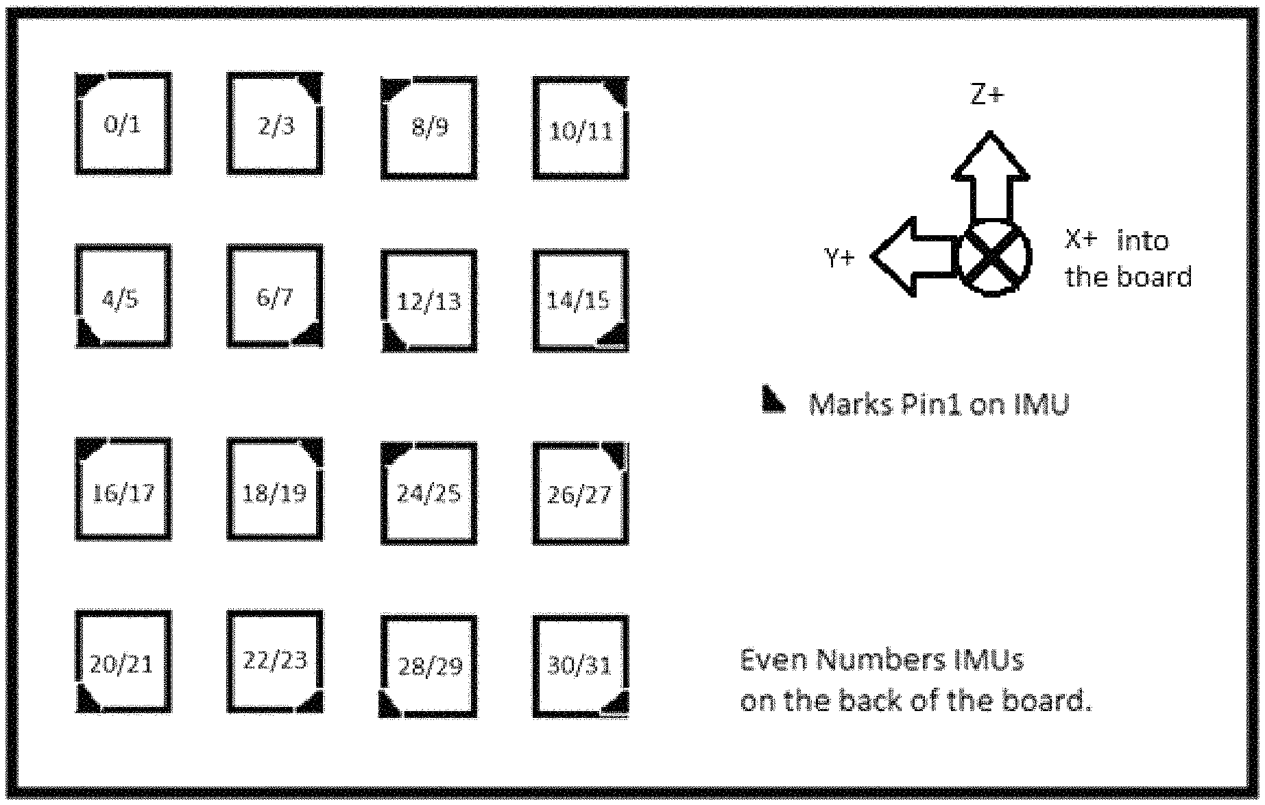
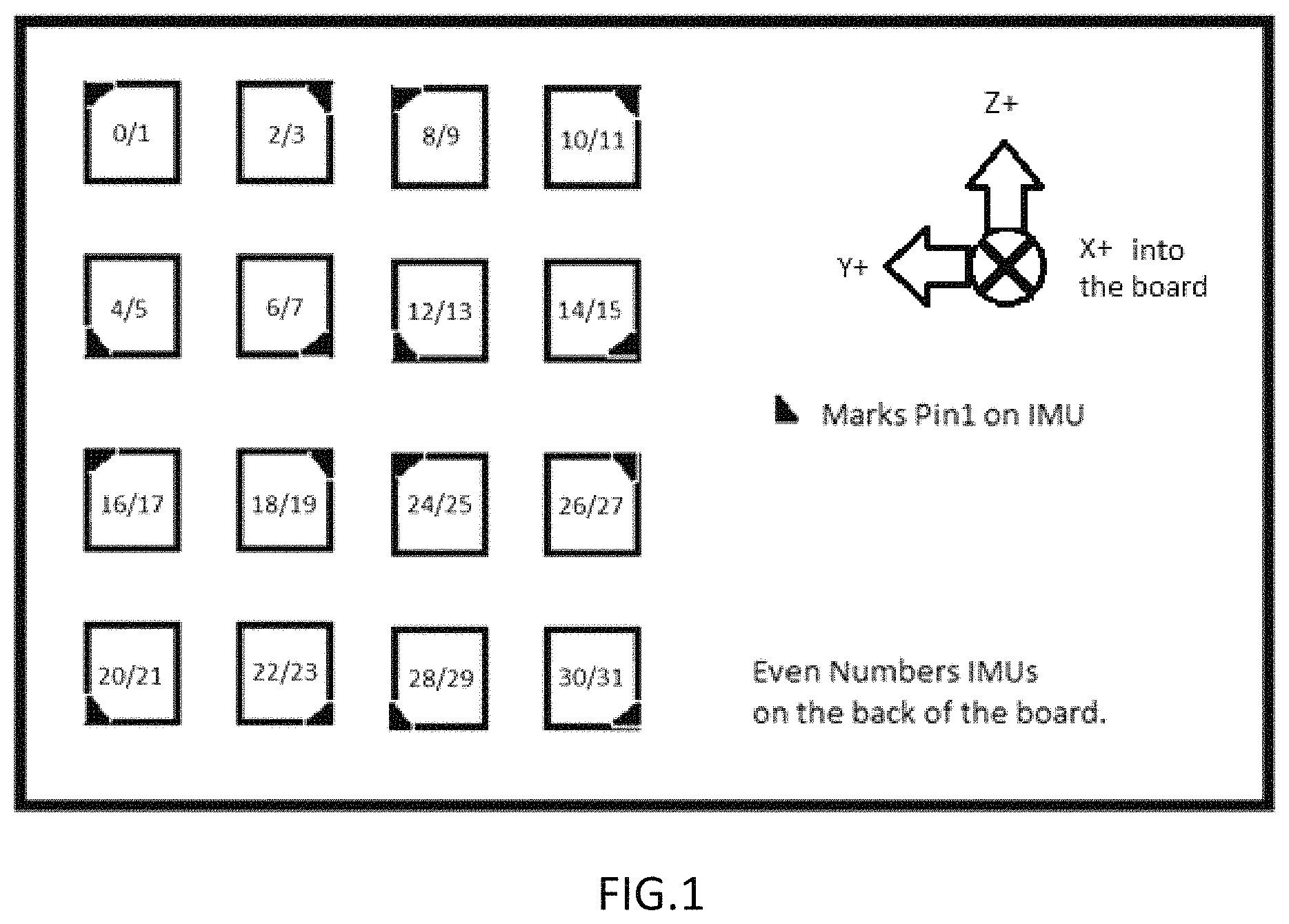
FIG. 1. Schematic diagram depicting one embodiment of the invention with multiple IMUs configured on a single printed circuit board.
FIG. 2. Diagram depicting the orientation of the axes of sensitivity and the polarity of rotation for the accelerometer and gyroscope of a low-resolution IMU.
FIG. 3. Diagram depicting the orientation of the axes of sensitivity for a compass of a low-resolution IMU.
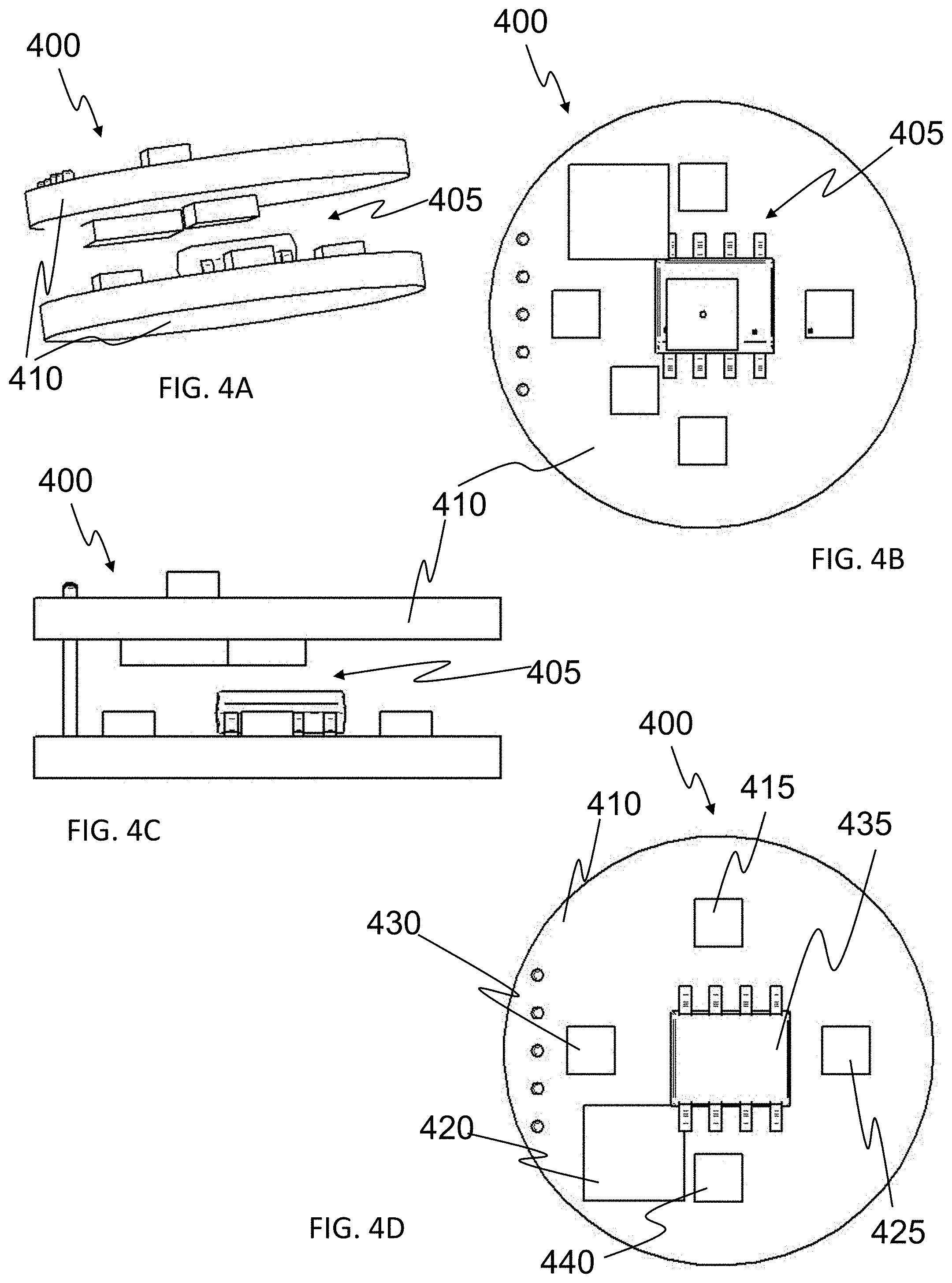
FIGS. 4A-D. Several views of one embodiment of an individual low-end IMU on a circuit board depicting various sensors, such views including A) perspective view, B) circuit diagram, C) side view, and D) top view.
DETAILED DESCRIPTION OF THE INVENTION AND DRAWINGS
The present invention relates to systems and methods for providing location and guidance, and more particularly for providing location and guidance in environments where global position systems (GPS) are unavailable or unreliable (GPS denied and/or degraded environments). The present invention further relates to systems and methods for using inertial measurement units IMUs to provide location and guidance. More particularly, the present invention relates to the use of a series of low-accuracy or low-resolution IMUs, in combination, to provide high-accuracy or high-resolution location and guidance results.
The present invention further utilizes an IMU comprising a sensor suite of preferably several sensors used to provide measurements including, but not limited to, body rates, linear accelerations and magnetic disturbance data measurements useful for providing precise navigation and control of munitions, missiles, projectiles, vehicles, or the like, or precise location and guidance to individuals. The individual IMUs or multi-IMU of the present invention may be used as a standalone IMU, or can be integrated into a guidance electronic unit (GEU)/IMU to be utilized with various systems and devices. Each individual low-end IMU preferably comprises one or more sensors in various combinations, such sensors including, but not limited to accelerometers, gyroscopes, magnetometers, GPS sensors and separate integrated sensor suites. Further, the systems of the present invention utilize a range of sensors for maneuvering or stabilizing the round or vehicle during travel, or the individual. The sensors, for example, may be used to determine the round's, vehicle's or individual's relative position with respect to a moving target or target location, flow dynamics on a flow surface of a round or vehicle, and threats or obstacles in or around the round, vehicle or individual. The sensors for determining the relative position may include but are not limited to antennas for acquiring global positioning (GPS as mentioned above), magnetic sensors, solar detectors, and the like. The sensors for determining flow dynamics may include but are not limited to a static and/or dynamic pressure sensor, shear stress sensor (hot film anemometer, a direct measurement floating-element shear stress sensor), inertial measurement unit or system, and other sensors known to those skilled in the art whose signal could be used to estimate or determine flow condition such as separation on the surface of the round or vehicle, which would function as a trigger point for actuating a control system. The sensors for determining threats or obstacles in or around the round, vehicle or individual include but are not limited to radar detectors, laser detectors, chemical detectors, heat (or infrared) detectors, and the like. The sensors most useful for determining travel parameters of a round, vehicle or individual include accelerometers, magnetometers, IR sensors, rate gyros, and motor controller sensors.
The individual low-end IMUs further preferably comprise a processor or controller, more preferably a microcontroller, to integrate and process the sensor signals in order to supply output data related to the conditions measured by the sensors. The processor or controller can be predictive or can respond and actuate any number of other systems such as control systems, guidance and navigation or alarm or warning systems. The controller preferably utilizes one or more digital microprocessors to process signals provided by the various sensors and deliver deployment, activation, or actuation commands to these other systems. Preferably, the present invention utilizes at least one accelerometer (if one is used, then preferably it is a 3-axis accelerometer), but may preferably also include at least one gyroscope (again, if one, then a 3-axis gyroscope), a magnetometer, and/or separate integrated sensor package consisting of at least one or more of these same types of sensors, thus providing redundancy. This redundancy in sensor(s) serves at least two beneficial purposes and although multiple sensors may be used on any individual IMU, in many embodiments the redundancy is at least provided by the utilization of multiple individual low-end IMUs to create a multi-IMU system where redundancy is a result of measurement from at least two or more of the individual IMUs. First, it allows for a significant increase in precision with the customized separate sensor package but in a reduced sensor range (for example +/-16 G, 2,000 dps). The firmware of the IMUs is designed in such a manner that it will be able to adaptively switch between the separate integrated sensor package and the direct accelerometer/gyroscope combination in the IMU at the onset of saturation of each of the sensor's dynamic range. Second, this redundancy allows for an overdetermined system when used to estimate the state/orientation of the projectile. The outputs provided by the additional sensors are always available so that a robust, consistent solution will exist based on IMU outputs. The combination of individual sensors and the separate integrated sensor package allows the present invention to reduce footprint and increase capabilities of the IMUs, particularly when combined in multiples. An additional gyroscope may further be integrated to capture the high-spin environment prior to controlled flight. The IMUs are capable of adaptively transitioning between the gyroscope on separate integrated sensor package and that directly on the IMUs, or between groupings of IMUs.
The present invention still further utilizes, in many embodiments, a transceiver for communicating information between the multi-IMU system and a user. The transceiver is designed to send key information back to the user (e.g., warfighter, response vehicle, remote monitoring station and/or personnel), which can include images/video (EO/IR) and/or travel data (attitude, velocity, position, time of travel, etc.). This information can be used for target identification and prioritization, or location and navigation. The transceiver is designed to be scalable for multiple platforms. In the example of munitions or weaponry, the transceiver can be integrated with imaging technology in a low velocity 40 mm round to provide the user with target detection, identification and tracking. Or, the transceiver can be integrated into a 40 mm surveillance/observation round in order to provide the user strategic battlefield information including assessing battle damage. In this example, the imaging technologies, power management and integration information can be scaled among these varying applications. Other applications include communicating with UAVs/drones, performing target prioritization in flight and offering situational awareness information to the user. Preferably, the transceiver is a radio frequency (RF) transceiver that operates under a frequency-hopping spread spectrum (FHSS) method that rapidly changes and switches communication among a number of frequencies or channels in a pseudorandom sequence that is shared and known by both the transceiver and the remote interface. FHSS is a wireless technology that spreads its signal over rapidly changing frequencies. Each available frequency band is divided into sub-frequencies. Signals rapidly change ("hop") among these in a pre-determined order. Interference at a specific frequency will only affect the signal during that short interval. Further, the transceiver preferably communicates image and/or travel data in real-time. This real-time communication allows a remote user the ability to take control of the projectile or vehicle and perform user-controlled flight from a remote location, or to provide real-time feedback to an individual. The user is fed the image and flight data from the projectile, vehicle or individual in-travel, and through a user interface, send live commands or controls back to the projectile, vehicle or individual in-travel to guide, maneuver or otherwise control the projectile or vehicle, or provide feedback, information or guidance to an individual.
Many embodiments of the present invention further comprise at least one temperature sensor. At least one temperature sensor may be included in the multi-IMU system such that it measures a local temperature about the entire system. Alternatively, individual temperature sensors may be comprised in one or more of the individual low-end IMUs. With multiple temperature sensors, the temperate of each individual IMU or a grouping of IMUs may be obtained. Obtaining a localized temperature measurement, particularly when localized to individual IMUs or groups of IMUs, allows for temperature compensation to be performed. Temperature compensation allows the system to accommodate for differences in temperature between two or more of the individual low-end IMUs and the shift, drift, error, or other differences that can arise based on differing temperatures between the individual low-end IMUs. This is particularly important based on the need for redundancy in measurement between individual low-end IMUs. If one or a group of IMUs is at a different temperature than the rest or other groups, then the individual sensor measurements of each IMU may be skewed or inaccurate with respect to the rest. Thus, in many embodiments, it is important to include at least one, or more preferably a plurality of temperature sensors to allow the system to compensate for such differences in temperatures between individual low-end IMUs, or groups thereof, and ensure accurate and repeatable measurements for each IMU, or to perform the necessary calculations to account for such differences. Temperature sensor measurements may then be factored into the individual low-end IMU measurements such that the individual IMU calculations are normalized to a single IMU, or group thereof, and measurements can be made accurately across the entire multi-IMU system.
The present invention also includes a printed circuit board (PCB), or a series thereof, on which the individual IMUs are to be mounted. The PCB is intended to support and electrically connect each of the components, particularly a plurality of IMUs, attached thereto. Preferably, each PCB has an upper surface and a lower surface, and in many embodiments, both surfaces are electrically conductive and populated with a plurality of IMUs. Although has few as one IMU may be used, preferably multiple IMUs are utilized, and the number of PCBs employed depends on the number of IMUs. Each PCB may include as few as one IMU. More preferably each PCB includes at least two IMUs. Yet more preferably, each PCB includes at least 4 IMUS. Still more preferably, each PCB includes at least 6 IMUs. Even more preferably, each PCB includes at least 8 IMUs. Still yet more preferably, each PCB includes at least 10 IMUs. Even still more preferably, each PCB includes at least 12 IMUs. Still yet more preferably, each PCB includes at least 14 IMUs. Still more preferably, each PCB includes at least 16 IMUs. Yet still more preferably, each PCB includes at least 18 IMUs. Even yet more preferably, each PCB includes at least 20 IMUs. Even still more preferably, each PCB includes at least 22 IMUs. Yet even still more preferably, each PCB includes at least 24 IMUs. Even still yet more preferably, each PCB includes at least 26 IMUs. Still yet even more preferably, each PCB includes at least 28 IMUs. Even yet still more preferably, each PCB includes at least 28 IMUs. Yet still even more preferably, each PCB includes at least 30 IMUs. Still even yet more preferably, each PCB includes at least 32 IMUs. Even still yet more preferably, each PCB includes at least 34 IMUs. More preferably still, each PCB includes as many as 36 IMUs. Further, multiple PCBs may be combined as well to further multiply the number of individual low-end IMUs present in the multi-IMU system.
The total number of PCBs, and thus the total number of low-end IMUs, is only limited by the constraints of the application for which the multi-IMU systems are being designed. A multi-IMU for a projectile is limited at least in part by the size, shape, and aerodynamic requirements of the projectile. A multi-IMU for a first responder or military personnel is limited at least by the form factor of the housing and weight requirements for ease of use by the individual. A multi-IMU for an automobile or other vehicle is limited at least by the size and shape of the housing where the multi-IMU will be mounted. With respect to the constraints of each individual embodiment, it is preferable that the multi-IMU comprise at least one PCB board with a plurality of IMUs mounted on each board. More preferably, the multi-IMU comprises at least two PCB boards with a plurality of IMUs mounted on each board. Still more preferably, the multi-IMU comprises at least three PCB boards with a plurality of IMUs mounted on each board. Yet more preferably, the multi-IMU comprises at least four PCB boards with a plurality of IMUs mounted on each board. Even more preferably, the multi-IMU comprises five or more PCB boards with a plurality of IMUs mounted on each board. Given the number of PCB boards utilized for a given embodiment of the present invention, it is preferably that the multi-IMU system comprises at least 1 IMUs. More preferably, the multi-IMU system comprises at least 2 IMUs. Yet more preferably, the multi-IMU system comprises at least 4 IMUs. Still more preferably, the multi-IMU system comprises at least 8 IMUs. Even more preferably, the multi-IMU system comprises at least 12 IMUs. Still even more preferably, the multi-IMU system comprises at least 16 IMUs. Even yet more preferably, the multi-IMU system comprises at least 20 IMUs. Yet still more preferably, the multi-IMU system comprises at least 24 IMUs. Still yet more preferably, the multi-IMU system comprises at least 28 IMUs. Yet even more preferably, the multi-IMU system comprises at least 32 IMUs. Even still more preferably, the multi-IMU system comprises at least 36 IMUs. Even yet more preferably, the multi-IMU system comprises at least 40 IMUs. Yet even more preferably, the multi-IMU system comprises at least 44 IMUs. Even still more preferably, the multi-IMU system comprises at least 48 IMUs. Still even yet more preferably, the multi-IMU system comprises at least 52 IMUs. Even yet still more preferably, the multi-IMU system comprises at least 56 IMUs. Yet still even more preferably, the multi-IMU system comprises at least 60 IMUs. Yet more preferably, the multi-IMU system comprises at least 64 IMUs. Even yet more preferably, the multi-IMU system comprises at least 68 IMUs. Still more preferably, the multi-IMU system comprises at least 72 IMUs. Yet even more preferably, the multi-IMU system comprises at least 76 IMUs. Even still more preferably, the multi-IMU system comprises 80 or more IMUs. Again, the total number of low-end, low resolution IMUs is only limited by the number of boards that can fit within the constraints of the particular embodiment, and more IMUs contained in the multi-IMU leads to even greater accuracy and precision of measurement.
Depending on the number of IMUs that are present, the IMUs can be configured in a number of orientations and locations. Preferably, each surface of the PCB is divided into four quadrants, each individually separate but interconnected with the other through the wiring of the PCB as well as firmware contained in the processor(s) or microprocessor(s). Preferably, the IMUs, when mounted in multiples, are each mounted in a different geometric, directional and special orientation. An example of this orientational mounting can be found in FIG. 1. Mounting each IMU in a given quadrant in a different orientation allows for the multi-IMU sensor system to be largely self-calibrating. Redundant measurements are obtained from each individual IMU, but each is oriented differently, thus allowed the system to coordinate the measurements and calibrate the system based on the measurements of each IMU. If one IMU begins to drift or develops of bias or shift, the difference will be evident in relation to at least one of the many other IMUs present in most embodiments. Thus, the drifting IMU can be recalibrated to be accurate, or the shift/bias/drift can be accounted for in any ongoing measurements. Each surface of the PCB is effectively a two-dimensional surface upon which the IMUs are mounted. Accordingly, the IMUs are preferably mounted in a different orientation in the y-axis and z-axis of the given surface of the PCB, where the x-axis is that perpendicular to the surface of the PCH and going into and through the PCB. By way of example, if each IMU were to have an effective top or prime direction, then the top or prime direction of each IMU can be mounted on the surface of the PCB in a given quadrant such that each IMU in the quadrant faces a different direction. In this example, one may assume that if one IMU is mounted with its top or prime direction to the "north" of the PCB quadrant, then each of the other IMUs mounted within that quadrant should be mounted with their top or prime direction in a different direction relative to the y- and z-axes of the board. In most embodiments, each quadrant may include up to 4 IMUs, though with advancements in miniaturization, more IMUs may be configured within each quadrant. Thus, in many embodiments, each PCB may include up to 32 IMUs--4 in each quadrant of each surface. As noted above, each of the IMUs are interconnected both electrically through the conduits of the PCB, and through firmware. Various firmware routines can be envisioned linking the individual low-end IMUs such that the IMUs perform their measurements in any sequence, order, or combination thus providing redundant and substantially continuous measurement. Each of the individual IMUs exhibits a signal that corresponds to any one or more of the sensors contained thereon (e.g., accelerometer, gyroscope, magnetometer, temperature sensors, and the like). The IMU signal may contain a single sensor measurement or may be a combination thereof, or may be a semi-processed or processed version of any combination.
Preferably, the entire multi-IMU is presented in am miniaturized form factor. In this vain, preferably, the multi-IMU is adapted to be produced in a package size less than 3 in.sup.3. More preferably, the multi-IMU is adapted to be produced in a package size less than 2 in.sup.3. Still more preferably, the multi-IMU is adapted to be produced in a package size less than 1.5 in.sup.3. Yet more preferably, the multi-IMU is adapted to be produced in a package size less than 1 in.sup.3. Even more preferably, the multi-IMU is adapted to be produced in a package size less than 0.9 in.sup.3. Yet still more preferably, the multi-IMU is adapted to be produced in a package size less than 0.8 in.sup.3. Still even more preferably, the multi-IMU is adapted to be produced in a package size less than 0.75 in.sup.3. Even yet more preferably, the multi-IMU is adapted to be produced in a package size less than 0.7 in.sup.3. Yet even more preferably, the multi-IMU is adapted to be produced in a package size less than 0.6 in.sup.3. Even still more preferably, the multi-IMU is adapted to be produced in a package size less than 0.5 in.sup.3.
In order to coordinate the signals from each of the IMUs, the present invention employs one or more algorithms, either on a central processor or on individual processors comprised on one or more of the individual low-end IMUs. Preferably, one or more of the individual low-end IMUs comprise a processor or microprocessor in order to perform at least localized coordination, pre-processing, and/or processing of the signals from the local sensors and/or IMUs. These processors may also receive and execute commands from outside sources or from a global processor that is adapted to coordinate, process, and to some degree control individual processors or microprocessors. Preferably, at least one guidance algorithm is employed, and is adapted to coordinate and synchronize all of the data from the individual IMUs, and to combine them in a manner that yields a generalized, global output that represents the combined total of all of the individual IMU measurements, but is in the form of a single IMU measurement. In other words, the guidance algorithm synthesizes all of the individual IMU data and combines it such that the output of the guidance algorithm is that of a single IMU. Another important consideration for the present invention is the offset, bias, drift, shift and other error that occurs in each individual low-end IMU. In some embodiments, localized error correction algorithms may be employed on processors or microprocessors on individual low-end IMUs in order to detect and correct or take into account these sources of error in the individual IMUs. Such algorithms may be employed on each individual IMU, or they may be employed on a sub-group basis, for example where a microprocessor on one individual IMU of a quadrant on the PCB corrects of such errors among all of the IMUs on that quadrant, and then transmits error-corrected data for all IMUs on that quadrant to a global or central processor and guidance algorithm. Alternatively, the central or global processor and guidance algorithm may coordinate and synthesize the data from all IMUs, or groups of IMUs, and correct or account for the errors in each accordingly. The type of system and combination of algorithms depends on the form factor of the multi-IMU system, and the constraints thereof regarding size and computing power required for the various algorithmic options.
The multi-IMU systems and methods of the present invention further include the ability to perform calibration steps among the sensors of the various individual IMUs, and of the multi-IMU system as a whole. As noted, in one exemplary embodiment, the PCBs of the present invention are divided into quadrants with one or more individual low-end IMUs mounted on each quadrant, preferably in different orientations with respect to the X, Y- and Z-axes of the board. With such a configuration, each IMU preferably takes redundant measurements with the sensors thereof. Over time, each IMU is subject to varying forms and degrees of error, with various biases, shifts, drifts, and the like. With redundant measurement among multiple IMUs, the signals from the sensors of each IMU may be coordinated and synchronized such that the signals from all can be normalized to a common set point. Although all of the IMUs are subject to the onset of such error, the likelihood of all of the IMUs experiencing such error in the same measurements, at the same times, to the same degrees is very low. Accordingly, the individual sensor measurements can effectively be monitored and the onset of error noticed as time passes. Thus, any detected error in any measurement of any sensor of any of the IMUs may be corrected by recalibrating the individual sensor or IMU, or by accounting for the detected error in the calculations of the system. This calibration is even further augmented by sequentially sampling the measurements from individual IMUs or groups of IMUs, thus providing a continuing error-check algorithm and system that monitors and detects error in the individual sensor or IMU measurements, which can be correlated to the other IMUs or groups of IMUs in order to more rapidly detect such error. Thus, the sensors and IMUs re substantially continuously calibrated against the other sensors and IMUs, all of which are normalized to obtain accurate and precise measurements even in the presence or onset of error in an individual sensor or IMU.
Accuracy, for the purposes of the present invention, can be measured or determined in numerous ways or by numerous metrics. With respect to navigation and guidance, or more accurately the measurements of IMUs and their sensors, accuracy of IMUs may often be measured by an error measurement of Angular Random Walk (ARW) which is a measurement of noise or error in the operation of an IMU, or of an individual sensor comprised in the IMU. An acceptable ARW value for a typical commercial grade IMU may be on the order of approximately 5.degree./ hour; n acceptable ARW value for a typical industrial grade IMU may be on the order of approximately 3.degree./ hour; an acceptable ARW value for a typical tactical grade IMU may be on the order of approximately 0.07.degree./ hour; and an acceptable ARW value for a typical navigation grade IMU may be on the order of approximately 0.002.degree./ hour. It is the goal of the present invention to provide multi-IMU systems and methods utilizing lower grade IMUs to create a multi-IMU system that exhibits tactical or even navigation grade performance. Thus, although the individual IMUs mounted on each PCB may be of commercial or industrial grade, the overall multi-IMU system performance is actually close to that of tactical or navigation grade IMUs. Accordingly, it is preferable that the multi-IMU system exhibit an angular random walk (ARW) value of 5.degree./ hour or less. More preferably, the multi-IMU system exhibits an ARW of 4.degree./ hour or less. Still more preferably, the multi-IMU system exhibits an ARW of 3.degree./ hour or less. Yet more preferably, the multi-IMU system exhibits an ARW of 2.degree./ hour or less. Even more preferably, the multi-IMU system exhibits an ARW of 1.degree./ hour or less. Still yet more preferably, the multi-IMU system exhibits an ARW of 0.5.degree./ hour or less. Yet even more preferably, the multi-IMU system exhibits an ARW of 0.1.degree./ hour or less. Even still more preferably, the multi-IMU system exhibits an ARW of 0.07.degree./ hour or less. Yet still more preferably, the multi-IMU system exhibits an ARW of 0.05.degree./ hour or less. Still even more preferably, the multi-IMU system exhibits an ARW of 0.03.degree./ hour or less. Even yet more preferably, the multi-IMU system exhibits an ARW of 0.01.degree./ hour or less. Still even yet more preferably, the multi-IMU system exhibits an ARW of 0.009.degree./ hour or less. Even yet still more preferably, the multi-IMU system exhibits an ARW of 0.007.degree./ hour or less. Yet still even more preferably, the multi-IMU system exhibits an ARW of 0.005.degree./ hour or less. Even still yet more preferably, the multi-IMU system exhibits an ARW of 0.003.degree./ hour or less. Still yet even more preferably, the multi-IMU system exhibits an ARW of 0.002.degree./ hour or less. Yet even still more preferably, the multi-IMU system exhibits an ARW of 0.001.degree./ hour or less. The actual performance of the multi-IMU system may be dictated by the number of individual lower-grade IMUs that are used, which in turn may be dictated by the application and any constraints associated with such application.
Another way to gauge the performance of the multi-IMU system is by the relative improvement over the performance of any individual IMU contained therein. By such metrics, preferably the multi-IMU system exhibits an overall or global ARW that is less than 3/4 of the ARM of any individual lower-grade IMU comprised therein. More preferably the multi-IMU system exhibits an overall or global ARW that is less than 2/3 of the ARW of any individual lower-grade IMU comprised therein. Still more preferably, the multi-IMU system exhibits an overall or global ARW that is less than 1/3 of the ARW of any individual lower-grade IMU comprised therein. Yet more preferably, the multi-IMU system exhibits an overall or global ARW that is less than 1/4 of the ARW of any individual lower-grade IMU comprised therein. Even more preferably, the multi-IMU system exhibits an overall or global ARW that is less than 1/10 of the ARW of any individual lower-grade IMU comprised therein. Still yet more preferably, the multi-IMU system exhibits an overall or global ARW that is less than 1/20 of the ARW of any individual lower-grade IMU comprised therein. Yet even more preferably, the multi-IMU system exhibits an overall or global ARW that is less than 1/50 of the ARW of any individual lower-grade IMU comprised therein. Even still more preferably, the multi-IMU system exhibits an overall or global ARW that is less than 1/75 of the ARW of any individual lower-grade IMU comprised therein. Still even more preferably, the multi-IMU system exhibits an overall or global ARW that is less than 1/100 of the ARW of any individual lower-grade IMU comprised therein. Even yet more preferably, the multi-IMU system exhibits an overall or global ARW that is less than 1/200 of the ARW of any individual lower-grade IMU comprised therein. Yet still more preferably, the multi-IMU system exhibits an overall or global ARW that is less than 1/400 of the ARW of any individual lower-grade IMU comprised therein. Still even yet more preferably, the multi-IMU system exhibits an overall or global ARW that is less than 1/600 of the ARW of any individual lower-grade IMU comprised therein. Even yet still more preferably, the multi-IMU system exhibits an overall or global ARW that is less than 1/800 of the ARW of any individual lower-grade IMU comprised therein. Yet still even more preferably, the multi-IMU system exhibits an overall or global ARW that is less than 1/1000 of the ARW of any individual lower-grade IMU comprised therein. Still even yet more preferably, the multi-IMU system exhibits an overall or global ARW that is less than 1/1250 of the ARW of any individual lower-grade IMU comprised therein. Even still yet more preferably, the multi-IMU system exhibits an overall or global ARW that is less than 1/1500 of the ARW of any individual lower-grade IMU comprised therein. Still yet even more preferably, the multi-IMU system exhibits an overall or global ARW that is less than 1/1750 of the ARW of any individual lower-grade IMU comprised therein. Yet even still more preferably, the multi-IMU system exhibits an overall or global ARW that is less than 1/2000 of the ARW of any individual lower-grade IMU comprised therein. Even yet still more preferably, the multi-IMU system exhibits an overall or global ARW that is less than 1/2250 of the ARW of any individual lower-grade IMU comprised therein. Yet still even more preferably, the multi-IMU system exhibits an overall or global ARW that is less than 1/2500 of the ARW of any individual lower-grade IMU comprised therein. Still even yet more preferably, the multi-IMU system exhibits an overall or global ARW that is less than 1/2750 of the ARW of any individual lower-grade IMU comprised therein. Even more preferably still, the multi-IMU system exhibits an overall or global ARW that is less than 1/3000 of the ARW of any individual lower-grade IMU comprised therein. Alternatively these metrics may be expressed as percentages of the ARW of the low-grade IMU.
Other measurements of error may also be used alternatively or in addition to ARW in order to determine the level of performance of the multi-IMU system. With specific respect to accelerometer measurements, accelerometer bias error (ABE) may be measured and used to compare the accuracy of the multi-IMU system to an individual IMU comprised therein. An acceptable ABE value for a typical commercial grade IMU may be on the order of approximately 125 mG; an acceptable ABE value for a typical industrial grade IMU may be on the order of approximately 3 mG; an acceptable ABE value for a typical tactical grade IMU may be on the order of approximately 0.3 mG; and an acceptable ABE value for a typical navigation grade IMU may be on the order of approximately 0.025 mG. Accordingly, it is preferable that the multi-IMU system exhibit an overall average accelerometer bias error (ABE) value of 125 mG or less. More preferably, the multi-IMU system exhibits an average ABE of 100 mG or less. Still more preferably, the multi-IMU system exhibits an average ABE of 75 mG or less. Yet more preferably, the multi-IMU system exhibits an average ABE of 50 mG or less. Even more preferably, the multi-IMU system exhibits an average ABE of 25 mG or less. Still yet more preferably, the multi-IMU system exhibits an average ABE of 10 mG or less. Yet even more preferably, the multi-IMU system exhibits an average ABE of 5 mG or less. Even still more preferably, the multi-IMU system exhibits an average ABE of 3 mG or less. Yet still more preferably, the multi-IMU system exhibits an average ABE of 1 mG or less. Still even more preferably, the multi-IMU system exhibits an average ABE of 0.75 mG or less. Even yet more preferably, the multi-IMU system exhibits an average ABE of 0.5 mG or less. Still even yet more preferably, the multi-IMU system exhibits an average ABE of 0.25 mG or less. Even yet still more preferably, the multi-IMU system exhibits an average ABE of 0.1 mG or less. Yet still even more preferably, the multi-IMU system exhibits an average ABE of 0.08 mG or less. Even still yet more preferably, the multi-IMU system exhibits an average ABE of 0.0 G mG or less. Still yet even more preferably, the multi-IMU system exhibits an average ABE of 0.04 mG or less. Yet even still more preferably, the multi-IMU system exhibits an average ABE of 0.02 mG or less. Again, the actual performance of the multi-IMU system may be dictated by the number of individual lower-grade IMUs that are used, which in turn may be dictated by the application and any constraints associated with such application.
Similarly, errors due to misalignment of the accelerometer may lead to inaccuracy and errors in the measurement or calculation of pitch and/or roll. Misalignment calibration accuracy, measured by accelerometer axis alignment, is therefore another useful metric for gauging the accuracy of the present invention. Typical accelerometer axis alignment (AAA) values for commercial grade IMU may be on the order of approximately 10,000 .mu.rad or 0.57.degree.; typical AAA values for industrial grade IMU may be on the order of approximately 1,000 .mu.rad or 0.057.degree.; typical AAA values for tactical grade IMU may be on the order of approximately 100 .mu.rad or 0.057.degree.; and typical AAA values for navigation grade IMU may be on the order of approximately 50 .mu.rad or 0.0029.degree.. Accordingly, it is preferable that the multi-IMU system exhibit an overall average accelerometer axis alignment (AAA) value of less than 10,000 .mu.rad or 0.57.degree.. More preferably, the multi-IMU system exhibits an average AAA of less than 5,000 .mu.rad or 0.28.degree.. Still more preferably, the multi-IMU system exhibits an average AAA of less than 1,000 .mu.rad or 0.057.degree.. Yet more preferably, the multi-IMU system exhibits an average AAA of less than 500 .mu.rad or 0.028.degree.. Even more preferably, the multi-IMU system exhibits an average AAA of less than 100 .mu.rad or 0.0057.degree.. Still yet more preferably, the multi-IMU system exhibits an average AAA of less than 50 .mu.rad or 0.0029.degree.. Again, the actual performance of the multi-IMU system may be dictated by the number of individual lower-grade IMUs that are used, which in turn may be dictated by the application and any constraints associated with such application.
Still another useful metric for measuring the accuracy of the multi-IMU system is the accelerometer scale factor which can lead to error errors in the measured orientation. Typical accelerometer scale factor error (ASFE) values for commercial grade IMU may be on the order of approximately 100,000 ppm; typical ASFE values for industrial grade IMU may be on the order of approximately 1,000 ppm; typical ASFE values for tactical grade IMU may be on the order of approximately 350 ppm; and typical ASFE values for navigation grade IMU may be on the order of approximately 100 ppm. Accordingly, it is preferable that the multi-IMU system exhibit an overall average accelerometer scale factor error (ASFE) value of less than 100,000 ppm. More preferably, the multi-IMU system exhibits an average ASFE of less than 10,000 ppm. Still more preferably, the multi-IMU system exhibits an average ASFE of less than 1,000 ppm. Yet more preferably, the multi-IMU system exhibits an average ASFE of less than 500 ppm. Even more preferably, the multi-IMU system exhibits an average ASFE of less than 250 ppm. Still yet more preferably, the multi-IMU system exhibits an average ASFE of less than 100 ppm. Again, the actual performance of the multi-IMU system may be dictated by the number of individual lower-grade IMUs that are used, which in turn may be dictated by the application and any constraints associated with such application.
Yet another useful metric for measuring the accuracy of the multi-IMU system is the gyroscope scale factor which can lead to error of the integration of angular rates during dynamic motion. Typical gyroscope scale factor error (GSFE) values for commercial grade IMU may be on the order of approximately 60,000 ppm; typical GSFE values for industrial grade IMU may be on the order of approximately 500 ppm; typical GSFE values for tactical grade IMU may be on the order of approximately 100 ppm; and typical GFE values for navigation grade IMU may be on the order of approximately 5 ppm. Accordingly, it is preferable that the multi-IMU system exhibit an overall average gyroscope scale factor error (GSFE) value of less than 60,000 ppm. More preferably, the multi-IMU system exhibits an average GSFE of less than 1,000 ppm. Still more preferably, the multi-IMU system exhibits an average GSFE of less than 500 ppm. Yet more preferably, the multi-IMU system exhibits an average GSFE of less than 250 ppm. Even more preferably, the multi-IMU system exhibits an average GSFE of less than 100 ppm. Still yet more preferably, the multi-IMU system exhibits an average ASFE of less than 100 ppm. Even still more preferably, the multi-IMU system exhibits an average ASFE of less than 50 ppm. Still even more preferably, the multi-IMU system exhibits an average ASFE of less than 10 ppm. Yet even more preferably, the multi-IMU system exhibits an average ASFE of less than 5 ppm. Again, the actual performance of the multi-IMU system may be dictated by the number of individual lower-grade IMUs that are used, which in turn may be dictated by the application and any constraints associated with such application.
Similar to accelerometers above, errors due to misalignment of the gyroscope may lead to inaccuracy and errors in the measurement or calculation of angular rate vector. Misalignment calibration accuracy, measured by gyroscope axis alignment, is therefore another useful metric for gauging the accuracy of the present invention. Typical gyroscope axis alignment (GAA) values for commercial grade IMU may be on the order of approximately 10,000 gad or 3.6.degree.; typical GAA values for industrial grade IMU may be on the order of approximately 1,000 gad or 0.36.degree.; typical GAA values for tactical grade IMU may be on the order of approximately 100 gad or 0.036.degree.; and typical GAA values for navigation grade IMU may be on the order of approximately 5 gad or 0.0018.degree.. Accordingly, it is preferable that the multi-IMU system exhibit an overall average gyroscope axis alignment (GAA) value of less than 10,000 gad or 3.6.degree.. More preferably, the multi-IMU system exhibits an average GAA of less than 5,000 gad or 1.8.degree.. Still more preferably, the multi-IMU system exhibits an average GAA of less than 1,000 .mu.rad or 0.36.degree.. Yet more preferably, the multi-IMU system exhibits an average GAA of less than 500 .mu.rad or 0.18.degree.. Even more preferably, the multi-IMU system exhibits an average GAA of less than 100 .mu.rad or 0.036.degree.. Still yet more preferably, the multi-IMU system exhibits an average GAA of less than 50 .mu.rad or 0.018.degree.. Even still more preferably, the multi-IMU system exhibits an average GAA of less than 5 .mu.rad or 0.0018.degree.. Again, the actual performance of the multi-IMU system may be dictated by the number of individual lower-grade IMUs that are used, which in turn may be dictated by the application and any constraints associated with such application.
Now referring to the figures and drawings, FIG. 1 is a schematic diagram depicting an exemplary embodiment of the present invention wherein multiple IMUs are configured on a single printed circuit board. The y- and z-axis are those perpendicular to each other along each surface of the board, and the z-axis is that which is perpendicular to the surface of the board, and extends through the board. Individual low-grade IMUs are mounted on the board in any number of combinations as disclosed here, and are preferably mounted in different orientations with respect to the y- and z-axes of the board. The figure depicts pin markers on the individual IMUs indication a reference point on the IMUs, and show that they are each mounted in a different orientation. The depicted embodiment comprises 32 individual low-grade IMUs--16 on each side, and 4 each in a quadrant of each surface of the board. The difference in orientation of IMUs is specific to each grouping of 4 IMUs on a quadrant. Thus, each quadrant comprises 4 IMUs in different orientations, although IMUs on different quadrants may be of the same orientation. This configuration allows the system to calibrate the individual IMUs with respect to each other as well as to provide redundant measurements that allow for calibration assistance, error checking and overall increased accuracy.
FIG. 2 is a diagram depicting the orientation of axes of sensitivity and the polarity of rotation for the accelerometer and gyroscope of an individual low-end or low-resolution IMU of the present invention. The multi-IMU, in many embodiments, preferably includes a plurality of the IMUs depicted in the present figure. Each individual IMU in the multi-UMU system is preferably interconnected with the others, at least via firmware, and are arranged in any number of patterns on the upper or lover surface of a PCB. The system preferably includes at least one processor comprising one or more algorithms adapted to receive and integrate data from the individual IMUs in order to produce a unified guidance output and/or guidance metric that is a much more accurate and precise measurement than any of the individual IMUs could provide on its own. The system also preferably calibrates the individual IMUs (as depicted) based on their relative location and orientation to each other and their absolute position and location on the PCB within the multi-IMU system. Preferably, one or more of the individual IMUs are oriented on the PCB in different orientation with respect to the depicted axes. Differing orientations enables the system to perform its calibration for the individual IMUs with respect to each other and thus the multi-IMU system as a whole. Once calibrated, the individual IMUs provide a series of redundant measurements that serve to provide accurate data and measurements in each axis, and can be integrated to yield a much more high resolution system than any individual IMU is capable of on its own.
FIG. 3. is a diagram depicting the orientation of the axes of sensitivity for an optional compass of an individual low-end or low-resolution IMU of the present invention. The optional compass can help compensate for shift and/or bias in the other sensor(s) and provides an absolute frame of reference for the other sensor(s) present on the individual IMU, and thus aides in calibration of the individual IMU and more importantly the multi-IMU system.
FIGS. 4A-D include several views of one embodiment of an individual low-end IMU of the present invention depicting various sensors, such views including A) perspective view, B) top view, C) side view, and D) alternative embodiment top view. FIG. 4A depicts a perspective view of an individual low-end IMU 400. The IMU 400 comprises a plurality of sensors 405 mounted on to a surface of a PCB 410. The plurality of sensors 405 may include any number and variety of the sensors discussed herein or known in the art, but preferably at least one accelerometer is present. FIG. 4B depicts a top view of one embodiment of an individual low-end IMU 400 comprising a PCB 410 and a plurality of sensors 405. The plurality of sensors 405 are shown in an arrangement with multiple sensors located at different radii from the center of the PCB. Different individual IMUs 400 comprising a multi-IMU (not shown) will preferably comprise he plurality of sensors 405 oriented and arranged in different locations on the PCB in order to provide redundant measurements for calibration purposes and for error check in measurements between IMUs 400. FIG. 4C is a side view depiction of the individual low-end IMU comprising a plurality of sensors 405 mounted on one or more PCBs 410. FIG. 4D s depicts a top view of an alternative embodiment to that depicted in FIG. 4B, with a plurality of sensors mounted in different locations and orientations on the PCB 410. In the present embodiment, the IMU 400 includes a gyroscope 415, an accelerometer 420, a magnetometer 425, a processor or microprocessor 430, an integrated sensor suite 435 comprising one or more sensors (e.g., accelerometer, gyroscope, magnetometer, and the like), and a compass 440. This embodiment serves to show the numerous types of sensors and components that can be comprised on a single IMU, and when compared with FIGS. 4A-4c, depicts varying positioning and orientation of the sensors on the PCB 410. The separate integrated sensor suite 435 is a standalone unit that adds redundant sensors to the IMU 400 and preferably includes at least one or more of an accelerometer, gyroscope, magnetometer and processor or microprocessor. In the present invention, a number of these IMUs 400 are coupled together and together form a multi-IMU system as described herein.
It will be apparent to those skilled in the art that various modifications and variations can be made to the present invention without departing from the spirit and scope of the invention. Thus, it is intended that the present invention cover the modifications and variations of this invention provided they come within the scope of the appended claims and their equivalents.
* * * * *
uspto.report is an independent third-party trademark research tool that is not affiliated, endorsed, or sponsored by the United States Patent and Trademark Office (USPTO) or any other governmental organization. The information provided by uspto.report is based on publicly available data at the time of writing and is intended for informational purposes only.
While we strive to provide accurate and up-to-date information, we do not guarantee the accuracy, completeness, reliability, or suitability of the information displayed on this site. The use of this site is at your own risk. Any reliance you place on such information is therefore strictly at your own risk.
All official trademark data, including owner information, should be verified by visiting the official USPTO website at www.uspto.gov. This site is not intended to replace professional legal advice and should not be used as a substitute for consulting with a legal professional who is knowledgeable about trademark law.