Vehicle radar sensing system with enhanced accuracy using interferometry techniques
Duque Biarge , et al. March 30, 2
U.S. patent number 10,962,641 [Application Number 16/123,255] was granted by the patent office on 2021-03-30 for vehicle radar sensing system with enhanced accuracy using interferometry techniques. This patent grant is currently assigned to MAGNA ELECTRONICS INC.. The grantee listed for this patent is Magna Electronics Inc.. Invention is credited to Sergio Duque Biarge, Holger Hess, Jorge J. Jacome Munoz, Kalin Kabakchiev, Roaldje Nadjiasngar, Jagmal Singh.


| United States Patent | 10,962,641 |
| Duque Biarge , et al. | March 30, 2021 |
Vehicle radar sensing system with enhanced accuracy using interferometry techniques
Abstract
A sensing system for a vehicle includes at least one radar sensor disposed at the vehicle and having a field of sensing exterior of the vehicle. The at least one radar sensor includes multiple transmitting antennas and multiple receiving antennas. The transmitting antennas transmit signals and the receiving antennas receive the signals reflected off objects. Multiple scans of radar data sensed by the at least one radar sensor are received at a control, and a vehicle motion estimation is received at the control. The control, responsive to received scans of sensed radar data, detects the presence of one or more objects exterior the vehicle and within the field of sensing of the at least one radar sensor. The control, responsive to the received scans of sensed radar data and the received vehicle motion estimation, matches objects detected in the scans and determines angles toward the detected objects.
| Inventors: | Duque Biarge; Sergio (Munich, DE), Singh; Jagmal (Aschaffenburg, DE), Hess; Holger (Aschaffenburg, DE), Jacome Munoz; Jorge J. (Aschaffenburg, DE), Kabakchiev; Kalin (Frankfurt am Main, DE), Nadjiasngar; Roaldje (Aschaffenburg, DE) | ||||||||||
|---|---|---|---|---|---|---|---|---|---|---|---|
| Applicant: |
|
||||||||||
| Assignee: | MAGNA ELECTRONICS INC. (Auburn
Hills, MI) |
||||||||||
| Family ID: | 1000005454400 | ||||||||||
| Appl. No.: | 16/123,255 | ||||||||||
| Filed: | September 6, 2018 |
Prior Publication Data
| Document Identifier | Publication Date | |
|---|---|---|
| US 20190072667 A1 | Mar 7, 2019 | |
Related U.S. Patent Documents
| Application Number | Filing Date | Patent Number | Issue Date | ||
|---|---|---|---|---|---|
| 62555221 | Sep 7, 2017 | ||||
| Current U.S. Class: | 1/1 |
| Current CPC Class: | G01S 13/4454 (20130101); G01S 13/931 (20130101); G01S 13/505 (20130101); G01S 13/9011 (20130101); G01S 2013/9315 (20200101); G01S 2013/932 (20200101); G01S 2013/9314 (20130101); G01S 2013/9317 (20130101) |
| Current International Class: | G01S 13/931 (20200101); G01S 13/50 (20060101); G01S 13/44 (20060101); G01S 13/90 (20060101) |
References Cited [Referenced By]
U.S. Patent Documents
| 4943796 | July 1990 | Lee |
| 5550677 | August 1996 | Schofield et al. |
| 5585798 | December 1996 | Yoshioka et al. |
| 5670935 | September 1997 | Schofield et al. |
| 5715093 | February 1998 | Schierbeek et al. |
| 5796094 | August 1998 | Schofield et al. |
| 5877897 | March 1999 | Schofield et al. |
| 5949331 | September 1999 | Schofield et al. |
| 6057754 | May 2000 | Kinoshita et al. |
| 6067110 | May 2000 | Nonaka et al. |
| 6085151 | July 2000 | Farmer et al. |
| 6097023 | August 2000 | Schofield et al. |
| 6118401 | September 2000 | Tognazzini |
| 6118410 | September 2000 | Nagy |
| 6201642 | March 2001 | Bos |
| 6216540 | April 2001 | Nelson et al. |
| 6313454 | November 2001 | Bos et al. |
| 6353392 | March 2002 | Schofield et al. |
| 6396397 | May 2002 | Bos et al. |
| 6492935 | December 2002 | Higuchi |
| 6498620 | December 2002 | Schofield et al. |
| 6580385 | June 2003 | Winner et al. |
| 6587186 | July 2003 | Bamji et al. |
| 6674895 | January 2004 | Ratii et al. |
| 6678039 | January 2004 | Charbon |
| 6690268 | February 2004 | Schofield et al. |
| 6690354 | February 2004 | Sze |
| 6710770 | March 2004 | Tomasi et al. |
| 6717610 | April 2004 | Bos et al. |
| 6757109 | June 2004 | Bos |
| 6771208 | August 2004 | Lutter et al. |
| 6795014 | September 2004 | Cheong |
| 6825455 | November 2004 | Schwarte |
| 6831591 | December 2004 | Horibe |
| 6876775 | April 2005 | Torunoglu |
| 6903677 | June 2005 | Takashima et al. |
| 6906793 | June 2005 | Bamji et al. |
| 6919549 | July 2005 | Bamji et al. |
| 6941211 | September 2005 | Kuroda et al. |
| 6946978 | September 2005 | Schofield |
| 7004606 | February 2006 | Schofield |
| 7005974 | February 2006 | McMahon et al. |
| 7012560 | March 2006 | Braeuchle et al. |
| 7038577 | May 2006 | Pawlicki et al. |
| 7042389 | May 2006 | Shirai |
| 7053357 | May 2006 | Schwarte |
| 7123168 | October 2006 | Schofield |
| 7157685 | January 2007 | Bamji et al. |
| 7176438 | February 2007 | Bamji et al. |
| 7176830 | February 2007 | Horibe |
| 7203356 | April 2007 | Gokturk et al. |
| 7212663 | May 2007 | Tomasi |
| 7283213 | October 2007 | O'Connor et al. |
| 7310431 | December 2007 | Gokturk et al. |
| 7321111 | January 2008 | Bamji et al. |
| 7340077 | March 2008 | Gokturk et al. |
| 7352454 | April 2008 | Bamji et al. |
| 7375803 | May 2008 | Bamji |
| 7379100 | May 2008 | Gokturk et al. |
| 7379163 | May 2008 | Rafii et al. |
| 7405812 | July 2008 | Bamji |
| 7408627 | August 2008 | Bamji et al. |
| 7432848 | October 2008 | Munakata |
| 7526103 | April 2009 | Schofield et al. |
| 7613568 | November 2009 | Kawasaki |
| 7706978 | April 2010 | Schiffmann et al. |
| 7765065 | July 2010 | Stiller |
| 8013780 | September 2011 | Lynam |
| 8027029 | September 2011 | Lu et al. |
| 8698894 | April 2014 | Briggance |
| 9036026 | May 2015 | Dellantoni et al. |
| 9146898 | September 2015 | Ihlenburg et al. |
| 9575160 | February 2017 | Davis et al. |
| 9599702 | March 2017 | Bordes et al. |
| 9689967 | June 2017 | Stark et al. |
| 9753121 | September 2017 | Davis et al. |
| 2003/0138132 | July 2003 | Stam et al. |
| 2003/0201929 | October 2003 | Lutter et al. |
| 2005/0104089 | May 2005 | Engelmann et al. |
| 2006/0091654 | May 2006 | De Mersseman et al. |
| 2010/0001897 | January 2010 | Lyman |
| 2010/0245066 | September 2010 | Sarioglu et al. |
| 2011/0037640 | February 2011 | Schmidlin |
| 2013/0215271 | August 2013 | Lu |
| 2013/0246020 | September 2013 | Zeng |
| 2015/0054672 | February 2015 | Nakahama |
| 2016/0018524 | January 2016 | Zeng |
| 2016/0109571 | April 2016 | Zeng |
| 2017/0222311 | August 2017 | Hess et al. |
| 2017/0254873 | September 2017 | Koravadi |
| 2017/0276788 | September 2017 | Wodrich |
| 2017/0315231 | November 2017 | Wodrich |
| 2017/0356994 | December 2017 | Wodrich et al. |
| 2018/0015875 | January 2018 | May et al. |
| 2018/0045812 | February 2018 | Hess |
| 2018/0059236 | March 2018 | Wodrich et al. |
| 2018/0065623 | March 2018 | Wodrich et al. |
| 2018/0067194 | March 2018 | Wodrich et al. |
| 2018/0231635 | August 2018 | Woehlte |
| 2019/0072666 | March 2019 | Duque Biarge et al. |
| 2019/0072668 | March 2019 | Duque Biarge et al. |
| 2019/0072669 | March 2019 | Duque Biarge et al. |
| 1506893 | Feb 2005 | EP | |||
| 2011090484 | Jul 2011 | WO | |||
| WO 2018/0182722 | Mar 2017 | WO | |||
| 2018007995 | Jan 2018 | WO | |||
Other References
|
Rapp et al. "Probabilistic ego-motion estimation using multiple automotive radar sensors." Robotics and Autonomous Systems 89, 136-146, 2017. cited by applicant . Das et al., "Scan registration with multi-scale k-means normal distributions transform." Intelligent Robots and Systems (IROS), 2012 IEEE/RSJ International Conference on. IEEE, 2012. cited by applicant . Lundquist et al., "Estimation of the free space in front of a moving vehicle." 2009. cited by applicant . Schreier et al., "Robust free space detection in occupancy grid maps by methods of image analysis and dynamic B-spline contour tracking." Intelligent Transportation Systems (ITSC), 2012 15th International IEEE Conference on. IEEE, 2012. cited by applicant. |
Primary Examiner: Pham; Timothy X
Attorney, Agent or Firm: Honigman LLP
Parent Case Text
CROSS REFERENCE TO RELATED APPLICATION
The present application claims the filing benefits of U.S. provisional application Ser. No. 62/555,221, filed Sep. 7, 2017, which is hereby incorporated herein by reference in its entirety.
Claims
The invention claimed is:
1. A sensing system for a vehicle, said sensing system comprising: at least one radar sensor disposed at a vehicle equipped with said sensing system and having a field of sensing exterior of the equipped vehicle; wherein said at least one radar sensor comprises multiple transmitting antennas and multiple receiving antennas, and wherein said transmitting antennas transmit signals and said receiving antennas receive the signals reflected off objects; a control comprising a processor, wherein multiple scans of radar data sensed by said at least one radar sensor are received at said control and processed at the processor; wherein the received sensed radar data comprises radar data acquisitions for at least two consecutive scans by said at least one radar sensor; wherein said control generates interferometric phases by pairing scans and multiplying complex values of a target peak after beamforming of one scan of each pair by a conjugate of its corresponding complex value of the other scan of that pair; wherein a vehicle motion estimation is received at said control; wherein said control, responsive to processing at the processor of the received multiple scans of sensed radar data, detects the presence of one or more objects exterior the equipped vehicle and within the field of sensing of said at least one radar sensor; and wherein said control, responsive at least in part to processing at the processor of the received multiple scans of sensed radar data and the received vehicle motion estimation, matches objects detected in the multiple scans and determines angles toward the detected objects.
2. The sensing system of claim 1, wherein each radar data acquisition is time stamped.
3. The sensing system of claim 2, wherein said control determines the angles toward the detected objects responsive to a sensor position of said at least one sensor at the equipped vehicle.
4. The sensing system of claim 1, wherein said control flattens the interferometric phases by taking into account the vehicle motion and estimated target positioning by the scans.
5. The sensing system of claim 4, wherein said control determines if residual interferometric phases can be unwrapped.
6. The sensing system of claim 5, wherein, responsive to determination that residual interferometric phases can be unwrapped, said control unwraps the residual interferometric phases.
7. The sensing system of claim 1, wherein said control provides enhanced accuracy for at least one selected from the group consisting of (i) Doppler velocity of a detected target, (ii) azimuth angle of a detected target and (iii) elevation angle of a detected target.
8. The sensing system of claim 1, wherein a vision system of the equipped vehicle comprises at least one exterior viewing camera disposed at the equipped vehicle and an image processor for processing image data captured by the at least one camera, and wherein information is shared between said sensing system and the vision system of the equipped vehicle.
9. The sensing system of claim 1, wherein said sensing system comprises two or more individual radar sensors, each having multiple transmitting antennas and receiving antennas on an antenna array, and wherein information is shared between the individual radars operating in stereo to determine high definition radar reflection responses for objects detected by said sensing system.
10. The sensing system of claim 1, wherein said at least one radar sensor is disposed at a front portion of the equipped vehicle and senses forward of the equipped vehicle.
11. The sensing system of claim 1, wherein said sensing system provides an output for at least one driving assist system function selected from the group consisting of (i) automated parking, (ii) blind spot detection, (iii) cross traffic alert, (iv) lane change assist, (v) lane merge assist, (vi) automatic emergency braking, (vii) pedestrian detection, (viii) turn assist, (ix) terrain management, (x) collision mitigation and (xi) intersection collision mitigation.
12. A sensing system for a vehicle, said sensing system comprising: at least one radar sensor disposed at a vehicle equipped with said sensing system and having a field of sensing exterior of the equipped vehicle; wherein said at least one radar sensor comprises multiple transmitting antennas and multiple receiving antennas, and wherein said transmitting antennas transmit signals and said receiving antennas receive the signals reflected off objects; a control comprising a processor, wherein multiple scans of radar data sensed by said at least one radar sensor are received at said control and processed at the processor; wherein each radar data acquisition is time stamped; wherein a vehicle motion estimation is received at said control; wherein said control, responsive to processing at the processor of the received multiple scans of sensed radar data, detects the presence of one or more objects exterior the equipped vehicle and within the field of sensing of said at least one radar sensor; wherein said control, responsive at least in part to processing at the processor of the received multiple scans of sensed radar data and the received vehicle motion estimation, matches objects detected in the multiple scans and determines angles toward the detected objects; wherein said control generates interferometric phases by pairing scans and multiplying complex values of a target peak after beamforming of one scan of each pair by a conjugate of its corresponding complex value of the other scan of that pair, and wherein said control flattens the interferometric phases by taking into account the vehicle motion and estimated target positioning by the scans; wherein said control determines the angles toward the detected objects responsive to a sensor position of said at least one sensor at the equipped vehicle; and wherein said sensing system provides an output for at least one driving assist system function selected from the group consisting of (i) automated parking, (ii) blind spot detection, (iii) cross traffic alert, (iv) lane change assist, (v) lane merge assist, (vi) automatic emergency braking, (vii) pedestrian detection, (viii) turn assist, (ix) terrain management, (x) collision mitigation and (xi) intersection collision mitigation.
13. The sensing system of claim 12, wherein said control determines if residual interferometric phases can be unwrapped.
14. The sensing system of claim 13, wherein, responsive to determination that residual interferometric phases can be unwrapped, said control unwraps the residual interferometric phases.
15. The sensing system of claim 12, wherein said control provides enhanced accuracy for at least one selected from the group consisting of (i) Doppler velocity of a detected target, (ii) azimuth angle of a detected target and (iii) elevation angle of a detected target.
16. The sensing system of claim 12, wherein a vision system of the equipped vehicle comprises at least one exterior viewing camera disposed at the equipped vehicle and an image processor for processing image data captured by the at least one camera, and wherein information is shared between said sensing system and the vision system of the equipped vehicle.
Description
FIELD OF THE INVENTION
The present invention relates generally to a vehicle sensing system for a vehicle and, more particularly, to a vehicle sensing system that utilizes one or more sensors at a vehicle to provide a field of sensing at or around the vehicle.
BACKGROUND OF THE INVENTION
Use of imaging sensors or ultrasonic sensors or radar sensors in vehicle sensing systems is common and known. Examples of such known systems are described in U.S. Pat. Nos. 8,013,780 and 5,949,331 and/or U.S. publication No. US-2010-0245066 and/or International Publication No. WO 2011/090484, which are hereby incorporated herein by reference in their entireties.
SUMMARY OF THE INVENTION
The present invention provides a driver assistance system or sensing system for a vehicle that utilizes a sensor module or system disposed at the vehicle and comprising at least one radar sensor disposed at the vehicle and having a field of sensing exterior of the vehicle. The at least one radar sensor comprises multiple transmitting (Tx) antennas (transmitters) and receiving (Rx) antennas (receivers) to provide high definition, fine resolution in azimuth and/or elevation to determine high definition radar reflection responses for objects and surfaces detected by the system. The system includes a control, where outputs (such as radar data acquisitions of multiple scans) of the at least one radar sensor are communicated to the control, and where the control, responsive to the outputs of the at least one radar sensor, detects the presence of objects in the field of sensing of the radar sensor or sensors. The system uses multiple scans to generate a virtual array by the vehicle position change between the scans. The system provides enhanced accuracy in determining the location of a detected object relative to the vehicle and sensor(s).
The present invention provides a means to substantially or drastically refine target accuracy in automotive radar. The dimensions that can be improved using the system of the present invention include target Doppler velocity and angular estimation in azimuth and elevation angles. The improvement of these accuracies help to precisely locate a target in space. The refinement of target positioning and target velocity yield easier target tracking. This is directly related to a boost in the tracker performance.
These and other objects, advantages, purposes and features of the present invention will become apparent upon review of the following specification in conjunction with the drawings.
BRIEF DESCRIPTION OF THE DRAWINGS
FIG. 1 is a perspective view of a vehicle with a sensing system that incorporates a radar sensor in accordance with the present invention;
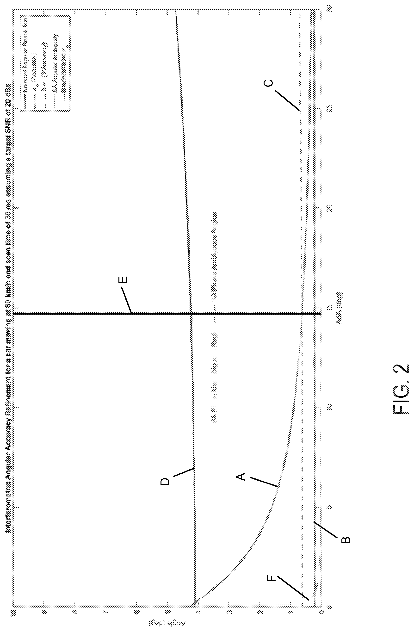
FIG. 2 is a graph showing azimuth angle of arrival accuracy comparison between the present invention and a single scan estimation for a target with a signal to noise ratio (SNR) of 20 dBs; and
FIG. 3 is a graph showing azimuth angle of arrival accuracy comparison between the present invention and a single scan estimation for a target with a SNR of 10 dBs.
DESCRIPTION OF THE PREFERRED EMBODIMENTS
A vehicle sensing system, such as a driver assist system, object detection system, parking assist system and/or alert system, operates to capture sensing data exterior of the vehicle and may process the captured data to detect objects or other vehicles at or near the equipped vehicle and in the predicted path of the equipped vehicle, such as to assist a driver of the equipped vehicle in maneuvering the vehicle in a forward or rearward direction or to assist the driver in parking the vehicle in a parking space. The system includes a processor that is operable to receive sensing data from one or more sensors and to provide an output to a control that, responsive to the output, generates an alert or controls an accessory or system of the vehicle, or highlights or overlays an alert on a display screen (that may be displaying video images captured by a single rearward viewing camera or multiple cameras providing forward, side or 360 degree surround views of the area surrounding the vehicle during a reversing or low speed maneuver of the vehicle).
Referring now to the drawings and the illustrative embodiments depicted therein, a vehicle 10 includes an driver assistance system or sensing system 12 that includes at least one radar sensor unit, such as a forward facing radar sensor unit 14 (and the system may optionally include multiple exterior facing sensors, such as multiple exterior facing radar sensors or cameras or other sensors, such as a rearward facing sensor at the rear of the vehicle, and a sideward/rearward facing sensor at respective sides of the vehicle), which sense regions exterior of the vehicle. The sensing system 12 includes a control or electronic control unit (ECU) or processor that is operable to process data captured by the sensor or sensors and may detect objects or the like. The data transfer or signal communication from the sensor to the ECU may comprise any suitable data or communication link, such as a vehicle network bus or the like of the equipped vehicle.
Some automotive radars use MIMO (Multiple Input Multiple Output) techniques to create an effective virtual antenna aperture, which is significantly larger than the real antenna aperture, and delivers much better angular resolution than conventional radars, such as, for example, conventional scanning radars.
The algorithms to estimate target positioning and target velocity on automotive radar typically use a single scan coherently or a set of scans incoherently. Coherent single scan algorithms use the complex values of different antenna phase centers for a particular range and then carries out beamforming in order to obtain the target's angular position. In this case, the angular accuracy is driven by the physical antenna array and the target's Signal-to-Noise Ratio (SNR). The integration scan time and target's SNR determine the target's Doppler accuracy. The second type of target positioning and Doppler estimator (incoherent set of scans) uses as an input a set of target list outputs from different scans. Thus, the values for every target are Doppler and Angle(s) (Azimuth Angle and potentially Elevation Angle for some sensors). The values are obtained independently for every scan and integrated through time. Thus, the accuracies are given by the incoherent sum of input accuracies.
The system of the present invention uses the coherent integration through different sets of scans. In that way, a virtual array is generated by the vehicle position change between scans. For example, a vehicle moving at 80 km/h with a radar scan time of 30 ms yields a virtual array size of 0.67 meters (i.e., the vehicle moves 0.67 meters every 30 ms). Thus, the virtual array in a different line of sight (LOS) direction is significantly larger with respect to the physical antenna. In terms of Doppler velocity, the improvement is achieved by having two scans that increase the scan integration time. In that dimension, the system of the present invention has increased performance as compared to the incoherent algorithms that use several scans to better estimate the accuracies. The improvement, in part, comes from having a larger integration time.
To increase target accuracy, the targets or objects are first matched between scans. Then interferometric data is generated. The interferometric phase for each target and each selected pairs of scans is generated by multiplying a scan's complex values of the target peak after beamforming by the conjugate of the scan's corresponding complex value of its scan pair. The number of independent interferometric phases gives the rank of the equation that the system is to solve. Thus, if, for example, the number of dimensions to be improved is three (e.g., Doppler Velocity, Azimuth angle and Elevation angle), the system needs at least three independent interferometric phases. In that example, the number of scans to group would be at least four.
The system of the present invention receives as inputs an ego motion estimation (an estimation of the motion of the measuring sensor that is disposed at the equipped or subject vehicle), a time stamp of each data acquisition or scan, a detection list for each scan with detected targets' positions, Doppler velocity and complex value after beamforming, and a sensor position of the measuring sensor with respect to the vehicle.
The dataflow includes, first, matching the targets or objects between scans. The interferometric phase is generated as previously described. The scans may be paired in different ways, for example, by pairing consecutive scans in order to minimize time decorrelation and the amount of data.
The next step is to "flatten" the interferometric phases by taking into account the vehicle movement and the estimated target positioning by the scans. This "phase flattening" can be done as a geometric approach by taking into account the different positions of the radar sensor and targets or objects.
The residual interferometric phases are related to the discrepancies of the estimated values and noise. An assessment to check if it is possible to correctly unwrap the residues is performed. In essence, this tests if the input accuracy can guarantee that the interferometric equation system can be solved unambiguously. Targets or objects with high SNR are more likely to be solved unambiguously. Then, the interferometric system is solved and provides as outputs the discrepancies of the dimensions introduced in the model with respect to the values used in the "phase flattening." Finally, the obtained discrepancies is added to the values used for "phase flattening" to get the absolute values.
For example, for an Azimuth dimension, the following parameters may be taken into account: a vehicle velocity of 80 km/h, a scan time of 30 ms, a sensor frequency of 79 GHz (i.e., a wavelength of 3.8 mm), 7 physical phase centers, and a 2 wavelength separation between physical phase centers. FIGS. 2 and 3 show the accuracy improvement vs target Azimuth Angle of Arrival (AoA) assuming a 20 dBs SNR (FIG. 2) and a 10 dBs SNR (FIG. 3). The SA Angular Ambiguity curve A is the interferometric ambiguity with respect to the AoA.
In order to assure that it is possible to unwrap the residual interferometric phase, the maximum error of the provided Azimuth angle by each scan has to be below this SA Angular Ambiguity line. The accuracy (one standard deviation) of a single scan AoA is plotted as a solid line B while the maximum error (three standard deviations) is plotted as a dotted line C. The accuracy and maximum error have the same shape as the nominal angular resolution line D. There is a scale factor depending on the target SNR. The solid vertical line E separates the angular area where the interferometric phase can be solved unambiguously (left side) and where it cannot be solved unambiguously (right side). The two accuracies to compare are the minimum error line B and the interferometric line F. A substantial azimuth accuracy improvement is readily achieved for targets or objects with low SNR.
Thus, the present invention refines accuracy in detecting targets or objects with automotive radar. The dimensions that are improved are, for example, target Doppler velocity and angular estimation in azimuth and elevation angles. The accuracy improvement helps to precisely localize a target in space. The refinement of target positioning and target velocity also yields easier target tracking. This directly leads to a boost in the tracker performance.
The system may provide an output for a driving assist system of the vehicle, such as one or more of (i) automated parking, (ii) blind spot detection, (iii) cross traffic alert, (iv) lane change assist, (v) lane merge assist, (vi) automatic emergency braking, (vii) pedestrian detection, (viii) turn assist, (ix) terrain management, (x) collision mitigation and (xi) intersection collision mitigation. Optionally, the output may be provided to an autonomous vehicle control system.
For autonomous vehicles suitable for deployment with the system of the present invention, an occupant of the vehicle may, under particular circumstances, be desired or required to take over operation/control of the vehicle and drive the vehicle so as to avoid potential hazard for as long as the autonomous system relinquishes such control or driving. Such occupant of the vehicle thus becomes the driver of the autonomous vehicle. As used herein, the term "driver" refers to such an occupant, even when that occupant is not actually driving the vehicle, but is situated in the vehicle so as to be able to take over control and function as the driver of the vehicle when the vehicle control system hands over control to the occupant or driver or when the vehicle control system is not operating in an autonomous or semi-autonomous mode.
Typically an autonomous vehicle would be equipped with a suite of sensors, including multiple machine vision cameras deployed at the front, sides and rear of the vehicle, multiple radar sensors deployed at the front, sides and rear of the vehicle, and/or multiple lidar sensors deployed at the front, sides and rear of the vehicle. Typically, such an autonomous vehicle will also have wireless two way communication with other vehicles or infrastructure, such as via a car2car (V2V) or car2x communication system. The forward viewing camera and/or the sensor of the lane determining system may comprise one of the cameras and/or one of the sensors of the autonomous vehicle control system.
The sensing system may include a machine vision system (comprising at least one exterior viewing camera disposed at the vehicle and an image processor for processing image data captured by the at least one camera), where information is shared between the stereo radar and the machine vision system.
The system may include two or more individual radars, having individual or multiple Tx (transmitters) and Rx (receivers) on an antenna array, and may utilize aspects of the systems described in U.S. Pat. Nos. 9,753,121; 9,689,967; 9,599,702; 9,575,160; 9,146,898; 9,036,026; 8,027,029; 8,013,780; 6,825,455; 7,053,357; 7,408,627; 7,405,812; 7,379,163; 7,379,100; 7,375,803; 7,352,454; 7,340,077; 7,321,111; 7,310,431; 7,283,213; 7,212,663; 7,203,356; 7,176,438; 7,157,685; 6,919,549; 6,906,793; 6,876,775; 6,710,770; 6,690,354; 6,678,039; 6,674,895 and/or 6,587,186, and/or International Publication Nos. WO 2018/007995 and/or WO 2011/090484, and/or U.S. Publication Nos. US-2018-0231635; US-2018-0045812; US-2018-0015875; US-2017-0356994; US-2017-0315231; US-2017-0276788; US-2017-0254873; US-2017-0222311 and/or US-2010-0245066, which are hereby incorporated herein by reference in their entireties.
Changes and modifications in the specifically described embodiments can be carried out without departing from the principles of the invention, which is intended to be limited only by the scope of the appended claims, as interpreted according to the principles of patent law including the doctrine of equivalents.
* * * * *
D00000
D00001
D00002
D00003
XML
uspto.report is an independent third-party trademark research tool that is not affiliated, endorsed, or sponsored by the United States Patent and Trademark Office (USPTO) or any other governmental organization. The information provided by uspto.report is based on publicly available data at the time of writing and is intended for informational purposes only.
While we strive to provide accurate and up-to-date information, we do not guarantee the accuracy, completeness, reliability, or suitability of the information displayed on this site. The use of this site is at your own risk. Any reliance you place on such information is therefore strictly at your own risk.
All official trademark data, including owner information, should be verified by visiting the official USPTO website at www.uspto.gov. This site is not intended to replace professional legal advice and should not be used as a substitute for consulting with a legal professional who is knowledgeable about trademark law.