Embedding thermally-resistant flexible cabling within a metal casting during die-casting
Dangler , et al. March 30, 2
U.S. patent number 10,960,463 [Application Number 16/190,943] was granted by the patent office on 2021-03-30 for embedding thermally-resistant flexible cabling within a metal casting during die-casting. This patent grant is currently assigned to International Business Machines Corporation. The grantee listed for this patent is International Business Machines Corporation. Invention is credited to Austin Carter, John R. Dangler, Colin E. Masterson, Gunnar Mills.


| United States Patent | 10,960,463 |
| Dangler , et al. | March 30, 2021 |
Embedding thermally-resistant flexible cabling within a metal casting during die-casting
Abstract
The present disclosure describes embedding thermally-resistant flexible cabling within a metal casting during die-casting. A die-casting process may include fixing the thermally-resistant flexible cabling within a die, and die-casting the metal to form a metal casting having the thermally-resistant flexible cabling embedded within the metal casting. In some cases, the thermally-resistant flexible cabling may be utilized for grounding of the metal casting.
| Inventors: | Dangler; John R. (Rochester, MN), Carter; Austin (Rochester, MN), Mills; Gunnar (Rochester, MN), Masterson; Colin E. (Rochester, MN) | ||||||||||
|---|---|---|---|---|---|---|---|---|---|---|---|
| Applicant: |
|
||||||||||
| Assignee: | International Business Machines
Corporation (Armonk, NY) |
||||||||||
| Family ID: | 1000005452401 | ||||||||||
| Appl. No.: | 16/190,943 | ||||||||||
| Filed: | November 14, 2018 |
Prior Publication Data
| Document Identifier | Publication Date | |
|---|---|---|
| US 20200147680 A1 | May 14, 2020 | |
| Current U.S. Class: | 1/1 |
| Current CPC Class: | B22D 19/00 (20130101); B22D 17/20 (20130101); C22C 18/04 (20130101) |
| Current International Class: | B22D 19/00 (20060101); B22D 17/20 (20060101); C22C 18/04 (20060101) |
References Cited [Referenced By]
U.S. Patent Documents
| 4739738 | April 1988 | Sander et al. |
| 5013507 | May 1991 | Julien et al. |
| 5996219 | December 1999 | Golnas et al. |
| 6015953 | January 2000 | Tosaka |
| 9500561 | November 2016 | Sutton |
| 2009/0309427 | December 2009 | Menhart |
| 2017/0021410 | January 2017 | Stumpf |
| 2017/0321661 | November 2017 | Mieritz et al. |
| 1046446 | Oct 2000 | EP | |||
| WO 2004/105176 | Dec 2004 | WO | |||
Other References
|
"Diecasting Alloys", Eastern Alloys Inc, Aug. 3, 2011, https://web.archive.org/web/20110803180616/http://www.eazall.com/diecasta- lloys.aspx (Eastern Alloys) (Year: 2011). cited by examiner . "Carbon Fiber", American Elements, Apr. 18, 2016, https://www.americanelements.com/carbon-fiber-7440-44-0 (American Elements) (Year: 2016). cited by examiner . "Metals--Melting Temperatures", The Engineering Toolbox, "Melting Temperatures of Some Common Metals and Alloys", Mar. 6, 2016, https://www.engineeringtoolbox.com/melting-temperature-metals-d_860.html (Engineering Toolbox) (Year: 2016). cited by examiner . "Dupont Pyralux HT", 2005, pp. 1-4 (Dupont) (Year: 2005). cited by examiner . Pille, C., In-Process Embedding of Piezo Sensors and RFID Transponders into Cast Parts for Autonomous Manufacturing Logistics, Smart Systems Integration, 4.sup.th Conference & Exhibition on Integration Issues of Miniaturized Systems--MEMS, MOEMS, OCs and Electronic Components, Como, Italy, ISBN 978-3-8007-3208-1, <<https://pdfs.semanticscholar.org/b96d/ba68173f18cdf464791f12ba067- 96a7fa7f4.pdf>>, Mar. 23-24, 2018, 10 pages. cited by applicant . Eastern Alloys Inc., Zinc Die Casting Alloys, <<https://www.eazall.com/diecastalloys.aspx>>, 2012, printed Jul. 10, 2018, 5 pages. cited by applicant. |
Primary Examiner: Schleis; Daniel J.
Assistant Examiner: Li; Kevin C T
Attorney, Agent or Firm: Rau; Nathan
Claims
What is claimed is:
1. An article of manufacture containing thermally-resistant flexible cabling, wherein a portion of the thermally-resistant flexible cabling is embedded within a metal casting during die-casting, wherein the thermally-resistant flexible cabling is resistant to melting at casting temperatures for zinc aluminum alloys, and wherein the portion of the thermally-resistant flexible cabling that is embedded within a body of the metal casting is grounded to the body of the metal casting.
2. The article of manufacture of claim 1, wherein the thermally-resistant flexible cabling is embedded within the metal casting during die-casting of a zinc aluminum alloy.
3. The article of manufacture of claim 1, wherein the thermally-resistant flexible cabling is utilized for grounding of the metal casting.
4. The article of manufacture of claim 3, wherein the article of manufacture further includes a grounding interconnect within the body of the metal casting, wherein the grounding interconnect has an airtight seal.
5. The article of manufacture of claim 3, wherein the thermally-resistant flexible cabling extends through a body of the metal casting to form a grounding interconnect.
6. The article of manufacture of claim 3, wherein the thermally-resistant flexible cabling is passed through the metal casting without post-machining.
7. The article of manufacture of claim 2, wherein the ZA alloy is zamak 3.
8. The article of manufacture of claim 1, wherein the zinc aluminum alloy is zamak 5.
9. The article of manufacture of claim 1, wherein the zinc aluminum alloy is one selected from a group consisting of zamak 7 and zamak 2.
10. A die-casting process comprising: fixing a thermally-resistant flexible cabling within a die; and after fixing the thermally-resistant flexible cabling within the die, die-casting an alloy to form a metal casting having a thermally-resistant flexible cabling embedded within the metal casting.
11. The die-casting process of claim 10, wherein die-casting the metal to form the metal casting comprises die-casting a zinc aluminum (ZA) alloy to form the metal casting.
12. The die-casting process of claim 11, wherein the ZA alloy is one selected from a group consisting of zamak 3, zamak 5, and zamak 7.
13. The die-casting process of claim 11, wherein the ZA alloy is zamak 2.
14. A process comprising: embedding a thermally-resistant flexible cabling within a metal casting during die-casting of a zinc aluminum (ZA) alloy; and utilizing the thermally-resistant flexible cabling for grounding of the metal casting.
15. The process of claim 14, wherein embedding the thermally-resistant flexible cabling within the metal casting during die-casting comprises embedding the thermally-resistant flexible cabling within the metal casting during die-casting of a zinc aluminum (ZA) alloy.
16. The process of claim 14, wherein the thermally-resistant flexible cabling extends through a body of the metal casting to form a grounding interconnect.
17. The process of claim 14, wherein the thermally-resistant flexible cabling is internally grounded within a body of the metal casting.
18. The process of claim 15, wherein the ZA alloy is one selected from a group consisting of zamak 3, zamak 5, and zamak 2.
19. The process of claim 15, wherein the ZA alloy is zamak 7.
Description
BACKGROUND
Passing cables through metal castings typically requires an additional mechanism or post-machining operations and assembly after forming the metal casting. The high temperatures required to cast metal has prevented cables from being embedded into metal for grounding, shielding, or communication. This has instead been accomplished with gasketing and physical contact.
SUMMARY
According to an embodiment, an article of manufacture containing thermally-resistant flexible cabling is disclosed. The thermally-resistant flexible cabling is embedded within a metal casting during die-casting.
According to another embodiment, a die-casting process includes fixing a thermally-resistant flexible cabling within a die. After fixing the thermally-resistant flexible cabling within the die, the process includes die-casting an alloy to form a metal casting having a thermally-resistant flexible cabling embedded within the metal casting.
According to yet another embodiment, a process includes embedding a thermally-resistant flexible cabling within a metal casting during die-casting. The process includes utilizing the thermally-resistant flexible cabling for grounding of the metal casting.
The foregoing and other objects, features, and advantages of the invention will be apparent from the following more particular descriptions of exemplary embodiments of the invention as illustrated in the accompanying drawings wherein like reference numbers generally represent like parts of exemplary embodiments of the invention.
BRIEF DESCRIPTION OF THE DRAWINGS
FIG. 1 is a prior art diagram depicting an example of a metal casting containing screw posts that are utilized to contact pads on a printed circuit board for grounding.
FIG. 2 is a diagram depicting an example of an article of manufacture containing thermally-resistant flexible cabling that is embedded within a metal casting, according to a particular embodiment.
FIG. 3 is a flow diagram depicting a particular embodiment of a process of embedding thermally-resistant flexible cabling within a metal casting during die-casting.
DETAILED DESCRIPTION
The present disclosure describes the utilization of thermally-resistant flexible cabling to embed cabling into or through metal castings for purposes of grounding the cast part or passing signals through the casting. In the present disclosure, thermally-resistant flexible cabling that is capable of withstanding the casting temperature of certain materials, such as various zinc aluminum (ZA) alloys (also commonly referred to as "zamak" materials), enables the cables to be embedded into a metal casting for grounding, shielding, or communication. Other materials or alloys may be used. In a particular embodiment, the thermally-resistant flexible cabling of the present disclosure may be able to withstand temperatures in the 450 to 500.degree. C. range for brief exposure, above the temperatures required to die-cast a variety of ZA alloys. Such cabling may include, for example, DuPont.TM. Pyralus.RTM. HT (heat resistant flexible cable).
Zamak is a family of alloys with a base metal of zinc and alloying elements of aluminum, magnesium, and copper. Zamak alloys are most commonly die-cast. To illustrate, zamak 3 has the base composition for the zamak alloys (96% zinc; 4% aluminum), with a solidification range (melting range) of 381-387.degree. C. Zamak 5 has the same composition as zamak 3 with the addition of 1% copper in order to increase strength, hardness, and corrosive resistance, with a solidification range (melting range) of 380-386.degree. C. Zamak 7 has less magnesium than zamak 3 in order to increase fluidity and ductility, with a solidification range (melting range) of 381-387.degree. C. Zamak 2 has the same composition as zamak 3 with the addition of 3% copper in order to increase strength, with a solidification range (melting range) of 379-390.degree. C. It will be appreciated that a variety of other ZA alloys may be suitable for the flexible cabling embedding operations described herein.
The cables may be passed through the metal castings without an additional mechanism or post-machining operations or assembly after forming the metal casting. Specifically, because the thermally-resistant flexible cabling is embedded within a metal casting during die-casting, no additional mechanism, post-machining operations, or assembly after forming the metal casting is necessary. Further, embedding a cable through the casting occupies a smaller amount of space than methods that utilize the post machining. Additionally, by embedding the thermally-resistant flexible cabling within the metal casting during die-casting, communications through the cast material may be transmitted at high-speed and with high-density.
FIG. 1 is a prior diagram 100 depicting an example of a metal casting containing screw posts 102 that are utilized to contact pads on a printed circuit board (not shown) for grounding. The example depicted in FIG. 1 represents an example of a "cubby/garage" including multiple channels 104 for passing individual cables.
When the metal casting is screwed onto a planar, the individual screw posts 102 align with copper pads on the printed circuit board that are electrically connected to a grounding layer on the printed circuit board. In the prior art design depicted in FIG. 1, screws go through the screw posts 102 and into an aluminum stiffener. The force of the stiffener pushes the backside of the screw posts 102 into the copper pads to establish grounding contacts 106. As described further herein with respect to FIG. 2, embedding thermally-resistant flexible cabling directly into a body 108 of the metal casting enables grounding by connection to a grounding plug on the printed circuit board, rather than using the screw posts 102 for contact.
FIG. 2 is a diagram 200 depicting an example of an article of manufacture containing thermally-resistant flexible cabling that is embedded within a metal casting, according to a particular embodiment. FIG. 2 represents an example of a grounding application where flexible thermally-resistant flexible cabling 210 with embedded, exposed metallurgy is used to create a grounding interconnect within the body 108 of the metal casting having an airtight seal. In contrast to the prior art example depicted in FIG. 1 where the screw posts 102 enable grounding contact, the addition of the thermally-resistant flexible cabling 210 directly into the body 108 enables the metal casting to be slotted into a grounding plug on the printed circuit board.
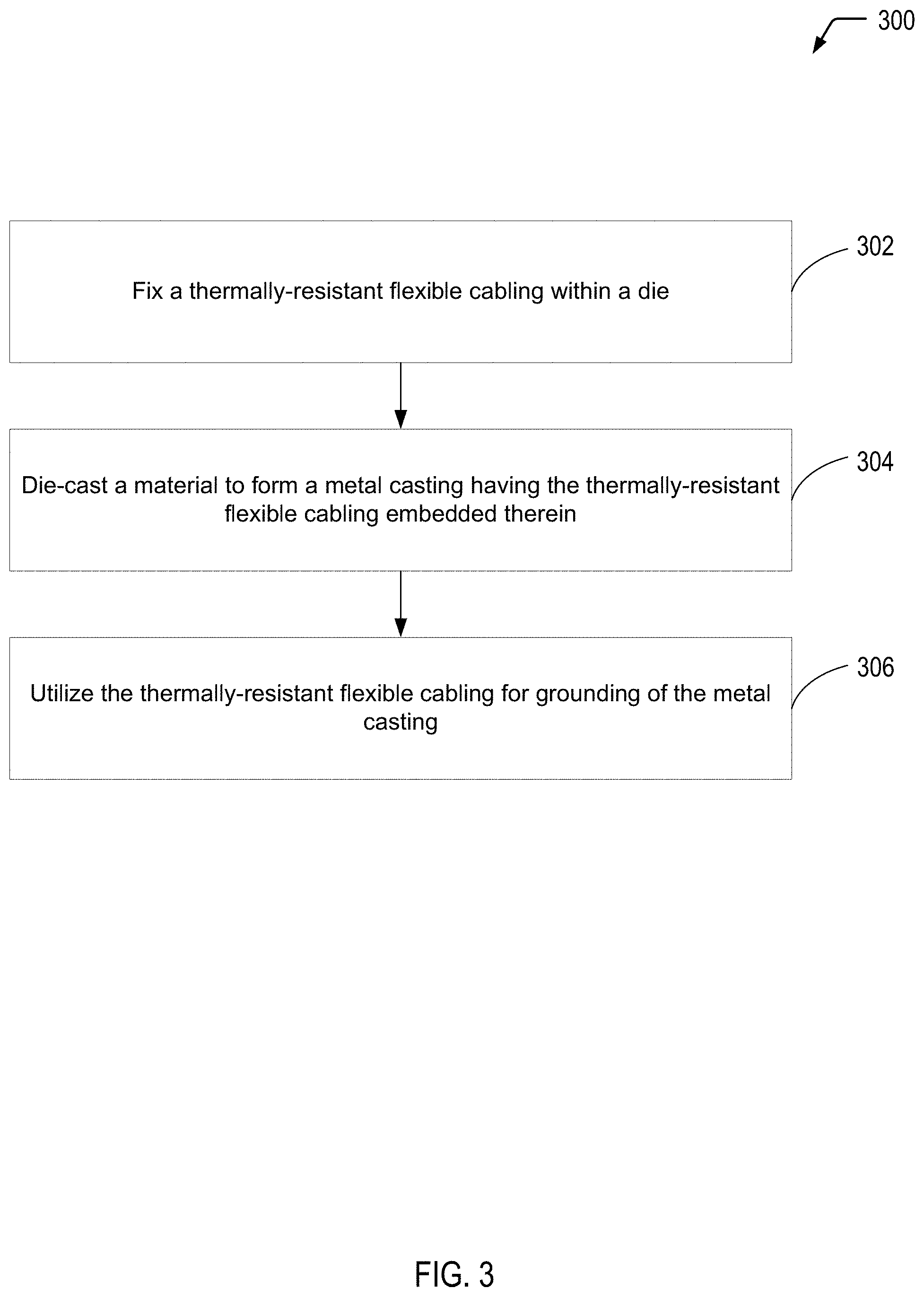
Referring to FIG. 3, a flow diagram illustrates an example of a process 300 of embedding thermally-resistant flexible cabling within a metal casting during die-casting, according to one embodiment. In the particular embodiment depicted in FIG. 3, the process 300 also includes utilizing the thermally-resistant flexible cabling for grounding of the metal casting. In alternative embodiments, the embedded thermally-resistant flexible cabling may be utilized for signal communication or shielding, among other alternatives.
The process 300 includes fixing a thermally-resistant flexible cabling within a die, at 302. For example, in the embodiment depicted in FIG. 2, the thermally-resistant flexible cabling 210 extends through the body 108 of the metal casting to form a grounding interconnect. In alternative embodiments, the thermally-resistant flexible cabling may be internally grounded within the body of the metal casting. The process 300 includes die-casting a material (such as a ZA alloy) to form a metal casting having the thermally-resistant flexible cabling embedded within the metal casting, at 304. For example, the ZA alloy may correspond to zamak 3, zamak 5, zamak 7, or zamak 2 (among other alternatives).
In the case of zamak 3 with a melting range of 381-387.degree. C., the thermally-resistant flexible cabling has sufficient high-temperature tolerance to withstand a die-casting temperature of at least 381.degree. C. In the case of zamak 5 with a melting range of 380-386.degree. C., the thermally-resistant flexible cabling has sufficient high-temperature tolerance to withstand a die-casting temperature of at least 380.degree. C. In the case of zamak 7 with a melting range of 381-387.degree. C., the thermally-resistant flexible cabling has sufficient high-temperature tolerance to withstand a die-casting temperature of at least 381.degree. C. In the case of zamak 2 with a melting range of 379-390.degree. C., the thermally-resistant flexible cabling has sufficient high-temperature tolerance to withstand a die-casting temperature of at least 379.degree. C.
In the particular embodiment depicted in FIG. 3, the process 300 further includes utilizing the thermally-resistant flexible cabling for grounding of the metal casting, at 306. For example, in the embodiment depicted in FIG. 2, the thermally-resistant flexible cabling 210 may be utilized for grounding of the metal casting.
It will be understood from the foregoing description that modifications and changes may be made in various embodiments of the present invention. The descriptions in this specification are for purposes of illustration only and are not to be construed in a limiting sense. The scope of the present invention is limited only by the language of the following claims.
* * * * *
References
D00000
D00001
D00002
D00003
XML
uspto.report is an independent third-party trademark research tool that is not affiliated, endorsed, or sponsored by the United States Patent and Trademark Office (USPTO) or any other governmental organization. The information provided by uspto.report is based on publicly available data at the time of writing and is intended for informational purposes only.
While we strive to provide accurate and up-to-date information, we do not guarantee the accuracy, completeness, reliability, or suitability of the information displayed on this site. The use of this site is at your own risk. Any reliance you place on such information is therefore strictly at your own risk.
All official trademark data, including owner information, should be verified by visiting the official USPTO website at www.uspto.gov. This site is not intended to replace professional legal advice and should not be used as a substitute for consulting with a legal professional who is knowledgeable about trademark law.