Flexible optical circuit, cassettes, and methods
Schneider , et al. March 23, 2
U.S. patent number 10,955,633 [Application Number 16/432,422] was granted by the patent office on 2021-03-23 for flexible optical circuit, cassettes, and methods. This patent grant is currently assigned to CommScope Asia Holdings B.V., CommScope Techologies LLC. The grantee listed for this patent is CommScope Asia Holdings B.V., CommScope Techologies LLC. Invention is credited to Alexander Dorrestein, James Joseph Eberle, Jr., Paul Schneider.


View All Diagrams
| United States Patent | 10,955,633 |
| Schneider , et al. | March 23, 2021 |
Flexible optical circuit, cassettes, and methods
Abstract
A fiber optic cassette includes a body defining a front and an opposite rear. A cable entry location, such as a multi-fiber connector, is defined on the body for a cable to enter the cassette, wherein a plurality of optical fibers from the cable extend into the cassette and form terminations at one or more single or multi-fiber connectors adjacent the front of the body. A flexible substrate is positioned between the cable entry location and the connectors adjacent the front of the body, the flexible substrate rigidly supporting the plurality of optical fibers. Each of the connectors adjacent the front of the body includes a ferrule. Dark fibers can be provided if not all fiber locations are used in the multi-fiber connectors. Multiple flexible substrates can be used with one or more multi-fiber connectors.
| Inventors: | Schneider; Paul (Gemonde, NL), Dorrestein; Alexander (Helmond, NL), Eberle, Jr.; James Joseph (Hummelstown, PA) | ||||||||||
|---|---|---|---|---|---|---|---|---|---|---|---|
| Applicant: |
|
||||||||||
| Assignee: | CommScope Asia Holdings B.V.
(Utrecht, NL) CommScope Techologies LLC (Hickory, NC) |
||||||||||
| Family ID: | 1000005439636 | ||||||||||
| Appl. No.: | 16/432,422 | ||||||||||
| Filed: | June 5, 2019 |
Prior Publication Data
| Document Identifier | Publication Date | |
|---|---|---|
| US 20190353863 A1 | Nov 21, 2019 | |
Related U.S. Patent Documents
| Application Number | Filing Date | Patent Number | Issue Date | ||
|---|---|---|---|---|---|
| 15875801 | Jan 19, 2018 | 10317638 | |||
| 14980789 | Jan 23, 2018 | 9874711 | |||
| 14045509 | Dec 29, 2015 | 9223094 | |||
| 61710519 | Oct 5, 2012 | ||||
| Current U.S. Class: | 1/1 |
| Current CPC Class: | G02B 6/3608 (20130101); G02B 6/4453 (20130101); G02B 6/3885 (20130101); G02B 6/4472 (20130101) |
| Current International Class: | G02B 6/44 (20060101); G02B 6/38 (20060101); G02B 6/36 (20060101) |
References Cited [Referenced By]
U.S. Patent Documents
| 4359262 | November 1982 | Dolan |
| 4502754 | March 1985 | Kawa |
| 4585303 | April 1986 | Pinsard et al. |
| 4595255 | June 1986 | Bhatt et al. |
| 4630886 | December 1986 | Lauriello et al. |
| 4699455 | October 1987 | Erbe et al. |
| 4708430 | November 1987 | Donaldson et al. |
| 4717231 | January 1988 | Dewez et al. |
| 4733936 | March 1988 | Mikolaicyk et al. |
| 4736100 | April 1988 | Vastagh |
| 4747020 | May 1988 | Brickley et al. |
| 4765710 | August 1988 | Burmeister et al. |
| 4792203 | December 1988 | Nelson et al. |
| 4824196 | April 1989 | Bylander |
| 4861134 | August 1989 | Alameel et al. |
| 4900123 | February 1990 | Barlow et al. |
| 4948220 | August 1990 | Violo et al. |
| 4971421 | November 1990 | Ori |
| 4986762 | January 1991 | Keith |
| 4989946 | February 1991 | Williams et al. |
| 4995688 | February 1991 | Anton et al. |
| 5011257 | April 1991 | Wettengel et al. |
| 5023646 | June 1991 | Ishida et al. |
| 5058983 | October 1991 | Corke et al. |
| 5067784 | November 1991 | Debortoli et al. |
| 5071211 | December 1991 | Debortoli et al. |
| 5073042 | December 1991 | Mulholland et al. |
| 5076688 | December 1991 | Bowen et al. |
| 5100221 | March 1992 | Carney et al. |
| 5109447 | April 1992 | Chan |
| 5127082 | June 1992 | Below et al. |
| 5129030 | July 1992 | Petrunia |
| 5138688 | August 1992 | Debortoli |
| 5142598 | August 1992 | Tabone |
| 5142606 | August 1992 | Carney et al. |
| 5155785 | October 1992 | Holland et al. |
| 5160188 | November 1992 | Rorke et al. |
| 5167001 | November 1992 | Debortoli et al. |
| 5179618 | January 1993 | Anton |
| 5204925 | April 1993 | Bonanni |
| 5208885 | May 1993 | Dragone et al. |
| 5212761 | May 1993 | Petrunia |
| 5214735 | May 1993 | Henneberger et al. |
| 5233674 | August 1993 | Vladic |
| 5235665 | August 1993 | Marchesi et al. |
| 5259051 | November 1993 | Burack |
| 5274729 | December 1993 | King et al. |
| 5274731 | December 1993 | White |
| 5287425 | February 1994 | Chang |
| 5289558 | February 1994 | Teichler et al. |
| 5292390 | March 1994 | Burack et al. |
| 5317663 | May 1994 | Beard et al. |
| 5318259 | June 1994 | Fussler |
| 5327513 | July 1994 | Nguyen et al. |
| 5333221 | July 1994 | Briggs et al. |
| 5333222 | July 1994 | Belenkiy et al. |
| 5335349 | August 1994 | Kutsch et al. |
| 5353367 | October 1994 | Czosnowski et al. |
| 5359688 | October 1994 | Underwood |
| 5363440 | November 1994 | Daoud |
| 5363465 | November 1994 | Korkowski et al. |
| 5363467 | November 1994 | Keith |
| 5367598 | November 1994 | Devenish, III et al. |
| 5402515 | March 1995 | Vidacovich et al. |
| 5408557 | April 1995 | Hsu |
| RE34955 | May 1995 | Anton et al. |
| 5412751 | May 1995 | Siemon et al. |
| 5420958 | May 1995 | Henson et al. |
| 5432875 | July 1995 | Korkowski et al. |
| 5442726 | August 1995 | Howard et al. |
| 5448015 | September 1995 | Jamet et al. |
| 5461690 | October 1995 | Lampert |
| 5469526 | November 1995 | Rawlings |
| 5490229 | February 1996 | Ghandeharizadeh et al. |
| 5497444 | March 1996 | Wheeler |
| 5511144 | April 1996 | Hawkins et al. |
| 5542015 | July 1996 | Hultermans |
| 5548678 | August 1996 | Frost et al. |
| 5570450 | October 1996 | Fernandez et al. |
| 5588076 | December 1996 | Peacock et al. |
| 5636138 | June 1997 | Gilbert et al. |
| 5636310 | June 1997 | Walles |
| 5647043 | July 1997 | Anderson et al. |
| 5664037 | September 1997 | Weidman |
| 5687266 | November 1997 | Leyssens |
| 5689604 | November 1997 | Janus et al. |
| 5708751 | January 1998 | Mattei |
| 5708753 | January 1998 | Frigo et al. |
| 5715348 | February 1998 | Falkenberg et al. |
| 5717810 | February 1998 | Wheeler |
| 5734776 | March 1998 | Puetz |
| 5734777 | March 1998 | Merriken et al. |
| 5742480 | April 1998 | Sawada et al. |
| 5758002 | May 1998 | Walters |
| 5758003 | May 1998 | Wheeler et al. |
| 5764844 | June 1998 | Mendes |
| 5774245 | June 1998 | Baker |
| 5774612 | June 1998 | Belenkiy et al. |
| 5781686 | July 1998 | Robinson et al. |
| 5784515 | July 1998 | Tamara et al. |
| 5823646 | October 1998 | Arizpe et al. |
| 5825955 | October 1998 | Ernst et al. |
| 5841917 | November 1998 | Jungerman et al. |
| 5870519 | February 1999 | Jenkins et al. |
| 5878179 | March 1999 | Schricker |
| 5883995 | March 1999 | Lu |
| 5887095 | March 1999 | Nagase et al. |
| 5889910 | March 1999 | Igl et al. |
| 5898811 | April 1999 | DiGiovanni |
| 5903698 | May 1999 | Poremba et al. |
| 5909526 | June 1999 | Roth et al. |
| 5930425 | July 1999 | Abel et al. |
| 5945633 | August 1999 | Ott et al. |
| 5956444 | September 1999 | Duda et al. |
| 5966492 | October 1999 | Bechamps et al. |
| 5969294 | October 1999 | Eberle et al. |
| 5970196 | October 1999 | Greveling et al. |
| 5974214 | October 1999 | Shacklette et al. |
| 5975769 | November 1999 | Larson et al. |
| 5981064 | November 1999 | Burack et al. |
| 5987203 | November 1999 | Abel et al. |
| 6005991 | December 1999 | Knasel |
| 6012852 | January 2000 | Kadar-Kallen et al. |
| 6027252 | February 2000 | Erdman et al. |
| 6041155 | March 2000 | Anderson et al. |
| 6044193 | March 2000 | Szentesi et al. |
| 6061492 | May 2000 | Strause et al. |
| 6076975 | June 2000 | Roth |
| 6079881 | June 2000 | Roth |
| 6097872 | August 2000 | Kusuda et al. |
| 6149315 | November 2000 | Stephenson |
| 6160946 | December 2000 | Thompson et al. |
| 6167183 | December 2000 | Swain |
| 6181845 | January 2001 | Horsthuis et al. |
| 6188687 | February 2001 | Mussman et al. |
| 6188825 | February 2001 | Bandy et al. |
| 6205278 | March 2001 | Sjolinder |
| 6208779 | March 2001 | Rowlette, Sr. et al. |
| 6208796 | March 2001 | Williams Vigliaturo |
| 6222976 | April 2001 | Shahid |
| 6224269 | May 2001 | Engstrand et al. |
| 6226431 | May 2001 | Brown et al. |
| 6227717 | May 2001 | Ott et al. |
| 6229933 | May 2001 | Curzio et al. |
| 6229942 | May 2001 | Engberg |
| 6234683 | May 2001 | Waldron et al. |
| 6236795 | May 2001 | Rodgers |
| 6240229 | May 2001 | Roth |
| 6256443 | July 2001 | Uruno |
| 6259844 | July 2001 | Logan et al. |
| 6271484 | August 2001 | Tokutsu |
| 6278829 | August 2001 | BuAbbud et al. |
| 6301413 | October 2001 | Bringuier |
| 6304690 | October 2001 | Day |
| 6317533 | November 2001 | Slater |
| RE37489 | January 2002 | Anton et al. |
| 6347888 | February 2002 | Puetz |
| 6351590 | February 2002 | Shahid |
| 6352374 | March 2002 | Selfridge et al. |
| 6356690 | March 2002 | McAlpine et al. |
| 6356697 | March 2002 | Braga et al. |
| 6360050 | March 2002 | Moua et al. |
| 6363200 | March 2002 | Thompson et al. |
| 6377738 | April 2002 | Anderson et al. |
| 6385381 | May 2002 | Janus et al. |
| 6411767 | June 2002 | Burrous et al. |
| 6424781 | July 2002 | Puetz et al. |
| 6425694 | July 2002 | Szilagyi et al. |
| 6431762 | August 2002 | Taira et al. |
| 6434313 | August 2002 | Clapp, Jr. et al. |
| 6442323 | August 2002 | Sorosiak |
| 6445866 | September 2002 | Clairadin et al. |
| 6452925 | September 2002 | Sistanizadeh et al. |
| 6453033 | September 2002 | Little et al. |
| 6464402 | October 2002 | Andrews et al. |
| 6464404 | October 2002 | Robinson et al. |
| D466087 | November 2002 | Cuny et al. |
| 6480487 | November 2002 | Wegleitner et al. |
| 6480661 | November 2002 | Kadar-Kallen et al. |
| 6483977 | November 2002 | Battey et al. |
| 6493480 | December 2002 | Lelic |
| 6496640 | December 2002 | Harvey et al. |
| 6504988 | January 2003 | Trebesch et al. |
| 6510273 | January 2003 | Ali et al. |
| 6526210 | February 2003 | Harrison et al. |
| 6532332 | March 2003 | Solheid et al. |
| 6535682 | March 2003 | Puetz et al. |
| 6537106 | March 2003 | Follingstad |
| 6539147 | March 2003 | Mahony |
| 6539160 | March 2003 | Battey et al. |
| 6542688 | April 2003 | Battey et al. |
| 6547450 | April 2003 | Lampert |
| 6554483 | April 2003 | Sun et al. |
| 6554485 | April 2003 | Beatty et al. |
| 6556763 | April 2003 | Puetz et al. |
| 6573451 | June 2003 | Komiya et al. |
| 6577595 | June 2003 | Counterman |
| 6591051 | July 2003 | Solheid et al. |
| 6594436 | July 2003 | Sun et al. |
| 6597670 | July 2003 | Tweedy et al. |
| 6600860 | July 2003 | Sun et al. |
| 6614980 | September 2003 | Mahony |
| 6619853 | September 2003 | Grois et al. |
| 6621975 | September 2003 | Laporte et al. |
| 6623170 | September 2003 | Petrillo |
| 6625375 | September 2003 | Mahony |
| 6631237 | October 2003 | Knudsen et al. |
| RE38311 | November 2003 | Wheeler |
| 6648376 | November 2003 | Christianson |
| 6654536 | November 2003 | Battey et al. |
| 6661961 | December 2003 | Allen et al. |
| 6668127 | December 2003 | Mahony |
| 6688780 | February 2004 | Duran |
| 6690862 | February 2004 | Rietveld |
| 6709607 | March 2004 | Hibbs-Brenner et al. |
| 6711339 | March 2004 | Puetz et al. |
| 6736670 | May 2004 | Clark et al. |
| 6755574 | June 2004 | Fujiwara et al. |
| 6760530 | July 2004 | Mandry |
| 6760531 | July 2004 | Solheid et al. |
| 6761585 | July 2004 | Clark et al. |
| 6763166 | July 2004 | Yow, Jr. et al. |
| 6764221 | July 2004 | de Jong et al. |
| 6775458 | August 2004 | Yow, Jr. et al. |
| 6778752 | August 2004 | Laporte |
| 6788786 | September 2004 | Kessler et al. |
| 6788846 | September 2004 | Hileman et al. |
| 6792190 | September 2004 | Xin et al. |
| 6792191 | September 2004 | Clapp, Jr. et al. |
| 6793517 | September 2004 | Neer et al. |
| 6796717 | September 2004 | Petrillo |
| 6801680 | October 2004 | Lin |
| 6815612 | November 2004 | Bloodworth et al. |
| 6819821 | November 2004 | Lacey et al. |
| 6843606 | January 2005 | Deane |
| 6845207 | January 2005 | Schray |
| 6850671 | February 2005 | Carnevale et al. |
| 6850685 | February 2005 | Tinucci et al. |
| 6853795 | February 2005 | Dagley et al. |
| 6870734 | March 2005 | Mertesdorf et al. |
| 6873773 | March 2005 | Sun et al. |
| 6888069 | May 2005 | Chen et al. |
| 6901200 | May 2005 | Schray |
| 6909833 | June 2005 | Henschel et al. |
| 6912349 | June 2005 | Clark et al. |
| 6916199 | July 2005 | Follingstad |
| 6920213 | July 2005 | Pershan |
| 6920274 | July 2005 | Rapp et al. |
| 6925241 | August 2005 | Bohle et al. |
| 6937800 | August 2005 | Cote |
| 6950593 | September 2005 | Hodge et al. |
| 6959139 | October 2005 | Erwin et al. |
| 6968111 | November 2005 | Trebesch et al. |
| 6980725 | December 2005 | Swieconek |
| 6983095 | January 2006 | Reagan et al. |
| H2144 | February 2006 | Baechtle et al. |
| 7020359 | March 2006 | Mayer |
| 7029322 | April 2006 | Ernst et al. |
| 7058245 | June 2006 | Farahi |
| 7062177 | June 2006 | Grivna |
| 7066762 | June 2006 | Neer et al. |
| 7066771 | June 2006 | Clark et al. |
| 7075565 | July 2006 | Raymond et al. |
| 7086539 | August 2006 | Knudsen et al. |
| 7088899 | August 2006 | Reagan et al. |
| 7090084 | August 2006 | Knudsen et al. |
| 7092592 | August 2006 | Verhagen et al. |
| 7094095 | August 2006 | Caveney |
| 7102884 | September 2006 | Mertesdorf et al. |
| 7103255 | September 2006 | Reagan et al. |
| 7130498 | October 2006 | Meis |
| 7139456 | November 2006 | Sasaki et al. |
| 7139461 | November 2006 | Puetz et al. |
| 7142764 | November 2006 | Allen et al. |
| 7142765 | November 2006 | Rapp et al. |
| 7146089 | December 2006 | Reagan et al. |
| 7149398 | December 2006 | Solheid et al. |
| 7171102 | January 2007 | Reagan et al. |
| 7179119 | February 2007 | Follingstad |
| 7186032 | March 2007 | Stevens et al. |
| 7194181 | March 2007 | Holmberg et al. |
| 7198409 | April 2007 | Smith et al. |
| 7200317 | April 2007 | Reagan et al. |
| 7218827 | May 2007 | Vongseng et al. |
| 7233731 | June 2007 | Solheid et al. |
| 7241182 | July 2007 | Clark et al. |
| 7244144 | July 2007 | Follingstad |
| 7277620 | October 2007 | Vongseng et al. |
| 7330546 | February 2008 | Kessler et al. |
| 7333707 | February 2008 | Puetz et al. |
| 7335056 | February 2008 | Clark et al. |
| 7346254 | March 2008 | Kramer et al. |
| 7357667 | April 2008 | Clark et al. |
| 7367823 | May 2008 | Rapp et al. |
| 7369741 | May 2008 | Reagan et al. |
| 7376321 | May 2008 | Bolster et al. |
| 7376322 | May 2008 | Zimmel et al. |
| 7376323 | May 2008 | Zimmel |
| 7377697 | May 2008 | Kahle et al. |
| 7391952 | June 2008 | Ugolini et al. |
| 7400813 | July 2008 | Zimmel |
| 7400816 | July 2008 | Reagan et al. |
| 7407330 | August 2008 | Smith et al. |
| 7408769 | August 2008 | Mertesdorf et al. |
| 7412147 | August 2008 | Scadden |
| 7416349 | August 2008 | Kramer |
| 7418181 | August 2008 | Zimmel et al. |
| 7433915 | October 2008 | Edwards et al. |
| 7455548 | November 2008 | Clark et al. |
| 7457503 | November 2008 | Solheid et al. |
| 7471869 | December 2008 | Reagan et al. |
| 7493002 | February 2009 | Coburn et al. |
| 7493044 | February 2009 | Kozischek et al. |
| 7515805 | April 2009 | Vongseng et al. |
| 7519259 | April 2009 | Vongseng et al. |
| 7532782 | May 2009 | Bragg |
| 7534135 | May 2009 | Follingstad |
| 7544090 | June 2009 | Follingstad |
| 7553091 | June 2009 | McColloch |
| 7555193 | June 2009 | Rapp et al. |
| 7623749 | November 2009 | Reagan et al. |
| 7627204 | December 2009 | Deane |
| 7646958 | January 2010 | Reagan et al. |
| 7686658 | March 2010 | Clark et al. |
| 7722261 | May 2010 | Kadar-Kallen et al. |
| 7738755 | June 2010 | Shioda |
| 7738760 | June 2010 | Fredrickson et al. |
| 7747125 | June 2010 | Lee et al. |
| RE41460 | July 2010 | Wheeler |
| 7773843 | August 2010 | Cody |
| 7775725 | August 2010 | Grinderslev |
| 7805043 | September 2010 | Puetz et al. |
| 7809232 | October 2010 | Reagan et al. |
| 7809233 | October 2010 | Smith et al. |
| 7809234 | October 2010 | Smith et al. |
| 7809235 | October 2010 | Reagan et al. |
| 7822313 | October 2010 | Rapp et al. |
| 7826706 | November 2010 | Vongseng et al. |
| 7841775 | November 2010 | Smith et al. |
| 7844159 | November 2010 | Solheid et al. |
| 7844161 | November 2010 | Reagan et al. |
| 7873255 | January 2011 | Reagan et al. |
| 7889961 | February 2011 | Cote et al. |
| 7934948 | May 2011 | Follingstad |
| 7942004 | May 2011 | Hodder |
| 7961999 | June 2011 | Frohlich et al. |
| 7983521 | July 2011 | Rapp et al. |
| 8019192 | September 2011 | Puetz et al. |
| 8032032 | October 2011 | Chand et al. |
| 8078017 | December 2011 | Kodama et al. |
| 8085472 | December 2011 | Kadar-Kallen |
| 8113723 | February 2012 | Togami |
| 8139913 | March 2012 | Bolster et al. |
| 8195022 | June 2012 | Coburn et al. |
| 8292518 | October 2012 | Togami |
| 8358900 | January 2013 | Rapp et al. |
| 8374477 | February 2013 | Hill |
| 8406587 | March 2013 | Mudd |
| 8417074 | April 2013 | Nhep et al. |
| 8428418 | April 2013 | Smrha |
| 8463091 | June 2013 | Kewitsch |
| 8600208 | December 2013 | Badar et al. |
| 8649648 | February 2014 | Coburn et al. |
| 8690593 | April 2014 | Anderson et al. |
| 8712206 | April 2014 | Cooke et al. |
| 9223094 | December 2015 | Schneider |
| 9874711 | January 2018 | Schneider |
| 2001/0041025 | November 2001 | Farahi |
| 2002/0034290 | March 2002 | Pershan |
| 2002/0097962 | July 2002 | Yoshimura et al. |
| 2002/0131719 | September 2002 | Grois et al. |
| 2002/0150372 | October 2002 | Schray |
| 2002/0181893 | December 2002 | White et al. |
| 2002/0181922 | December 2002 | Xin et al. |
| 2003/0002812 | January 2003 | Lampert |
| 2003/0007767 | January 2003 | Douglas et al. |
| 2003/0042040 | March 2003 | Komiya et al. |
| 2003/0044141 | March 2003 | Melton et al. |
| 2003/0072537 | April 2003 | Eichenberger et al. |
| 2003/0095772 | May 2003 | Solheid et al. |
| 2003/0147597 | August 2003 | Duran |
| 2003/0165315 | September 2003 | Trebesch et al. |
| 2003/0174953 | September 2003 | Carnevale et al. |
| 2003/0174996 | September 2003 | Henschel et al. |
| 2003/0180012 | September 2003 | Deane |
| 2003/0182015 | September 2003 | Domaille et al. |
| 2003/0223724 | December 2003 | Puetz et al. |
| 2004/0028368 | February 2004 | Hileman et al. |
| 2004/0074852 | April 2004 | Knudsen et al. |
| 2004/0109660 | June 2004 | Liberty |
| 2004/0126069 | July 2004 | Jong et al. |
| 2004/0136638 | July 2004 | Baechtle et al. |
| 2004/0165852 | August 2004 | Erwin et al. |
| 2004/0172492 | September 2004 | Farnworth et al. |
| 2004/0175090 | September 2004 | Vastmans et al. |
| 2004/0228598 | November 2004 | Allen et al. |
| 2004/0264873 | December 2004 | Smith et al. |
| 2005/0002633 | January 2005 | Solheid et al. |
| 2005/0003697 | January 2005 | Neer et al. |
| 2005/0018950 | January 2005 | Arellano |
| 2005/0048831 | March 2005 | Neer et al. |
| 2005/0053337 | March 2005 | Mayer |
| 2005/0084200 | April 2005 | Meis et al. |
| 2005/0129379 | June 2005 | Reagan et al. |
| 2006/0029353 | February 2006 | Bolster et al. |
| 2006/0093274 | May 2006 | Kahle et al. |
| 2006/0093301 | May 2006 | Zimmel et al. |
| 2006/0177175 | August 2006 | Mayer et al. |
| 2006/0210222 | September 2006 | Watte et al. |
| 2006/0210229 | September 2006 | Scadden |
| 2006/0228086 | October 2006 | Holmberg et al. |
| 2006/0245756 | November 2006 | Kozischek et al. |
| 2006/0269205 | November 2006 | Zimmel |
| 2006/0269206 | November 2006 | Zimmel |
| 2007/0025675 | February 2007 | Kramer |
| 2007/0047893 | March 2007 | Kramer et al. |
| 2007/0086694 | April 2007 | Murphy et al. |
| 2007/0189692 | August 2007 | Zimmel et al. |
| 2007/0230863 | October 2007 | Fukuda et al. |
| 2008/0008436 | January 2008 | Reagan et al. |
| 2008/0008437 | January 2008 | Reagan et al. |
| 2008/0019655 | January 2008 | Vongseng et al. |
| 2008/0025684 | January 2008 | Vongseng et al. |
| 2008/0089656 | April 2008 | Wagner et al. |
| 2008/0131067 | June 2008 | Ugolini et al. |
| 2008/0175548 | July 2008 | Knecht et al. |
| 2008/0273846 | November 2008 | Register |
| 2008/0317425 | December 2008 | Smith et al. |
| 2009/0041417 | February 2009 | Rapp et al. |
| 2009/0067800 | March 2009 | Vazquez et al. |
| 2009/0074372 | March 2009 | Solheid et al. |
| 2009/0087157 | April 2009 | Smith et al. |
| 2009/0097797 | April 2009 | Kewitsch |
| 2009/0097800 | April 2009 | Gurreri et al. |
| 2009/0097813 | April 2009 | Hill |
| 2009/0190896 | July 2009 | Smith et al. |
| 2009/0196565 | August 2009 | Vongseng et al. |
| 2009/0245743 | October 2009 | Cote et al. |
| 2009/0257726 | October 2009 | Redmann et al. |
| 2009/0269018 | October 2009 | Frohlich et al. |
| 2009/0274431 | November 2009 | Krampotich et al. |
| 2009/0285540 | November 2009 | Reagan et al. |
| 2009/0290843 | November 2009 | Reagan et al. |
| 2009/0297111 | December 2009 | Reagan et al. |
| 2009/0324189 | December 2009 | Hill et al. |
| 2010/0124421 | May 2010 | Chand et al. |
| 2010/0129028 | May 2010 | Nhep et al. |
| 2010/0142910 | June 2010 | Hill et al. |
| 2010/0166370 | July 2010 | Cody |
| 2010/0238428 | September 2010 | Glines et al. |
| 2010/0316335 | December 2010 | Furuyama |
| 2010/0322562 | December 2010 | Barnes et al. |
| 2010/0322576 | December 2010 | Rhoney et al. |
| 2010/0322577 | December 2010 | Bolster et al. |
| 2010/0322579 | December 2010 | Cooke et al. |
| 2011/0019964 | January 2011 | Nhep et al. |
| 2011/0044599 | February 2011 | Kowalczyk et al. |
| 2011/0065909 | March 2011 | Lange et al. |
| 2011/0081114 | April 2011 | Togami |
| 2011/0085771 | April 2011 | Matsuyama et al. |
| 2011/0096404 | April 2011 | Kadar-Kallen |
| 2011/0110673 | May 2011 | Elberbaum |
| 2011/0182558 | July 2011 | Garcia et al. |
| 2011/0222829 | September 2011 | Loeffelholz et al. |
| 2011/0262077 | October 2011 | Anderson et al. |
| 2011/0268414 | November 2011 | Giraud et al. |
| 2011/0274400 | November 2011 | Mudd |
| 2011/0317973 | December 2011 | Rapp et al. |
| 2012/0008900 | January 2012 | Schneider |
| 2012/0014645 | January 2012 | Kadar-Kallen |
| 2012/0020618 | January 2012 | Erdman et al. |
| 2012/0020619 | January 2012 | Kadar-Kallen et al. |
| 2012/0051706 | March 2012 | Van Geffen et al. |
| 2012/0051708 | March 2012 | Badar et al. |
| 2012/0148198 | June 2012 | Togami |
| 2012/0189259 | July 2012 | Manes |
| 2012/0263415 | October 2012 | Tan et al. |
| 2012/0301098 | November 2012 | Benedetto et al. |
| 2013/0064495 | March 2013 | Eberle, Jr. |
| 2013/0064506 | March 2013 | Eberle et al. |
| 2013/0077913 | March 2013 | Schneider et al. |
| 2013/0089292 | April 2013 | Ott et al. |
| 2014/0270636 | September 2014 | Manes |
| 40995/85 | Apr 1985 | AU | |||
| 55314/86 | Mar 1986 | AU | |||
| 2426610 | Apr 2001 | CN | |||
| 27 35 106 | Feb 1979 | DE | |||
| 33 08 682 | Sep 1984 | DE | |||
| 42 07 531 | Sep 1992 | DE | |||
| 42 29 510 | Mar 1994 | DE | |||
| 0 146 478 | Jun 1985 | EP | |||
| 0 149 250 | Jul 1985 | EP | |||
| 0 196 102 | Oct 1986 | EP | |||
| 0 211 208 | Feb 1987 | EP | |||
| 0 293 183 | Nov 1988 | EP | |||
| 0 349 290 | Jan 1990 | EP | |||
| 0 406 151 | Jan 1991 | EP | |||
| 0 479 226 | Apr 1992 | EP | |||
| 0 196 102 | Mar 1993 | EP | |||
| 0 538 164 | Apr 1993 | EP | |||
| 0 585 809 | Mar 1994 | EP | |||
| 0587336 | Mar 1994 | EP | |||
| 0 697 610 | Feb 1996 | EP | |||
| 0 743 701 | Nov 1996 | EP | |||
| 0 788 002 | Aug 1997 | EP | |||
| 0 871 047 | Oct 1998 | EP | |||
| 0 563 995 | Oct 1999 | EP | |||
| 0 975 180 | Jan 2000 | EP | |||
| 1 045 267 | Oct 2000 | EP | |||
| 1102095 | May 2001 | EP | |||
| 1103832 | May 2001 | EP | |||
| 1067418 | Oct 2001 | EP | |||
| 2 531 576 | Feb 1984 | FR | |||
| 2 587 127 | Mar 1987 | FR | |||
| 2367902 | Oct 2000 | GB | |||
| 59-74523 | Apr 1984 | JP | |||
| 60-169811 | Sep 1985 | JP | |||
| 61-55607 | Mar 1986 | JP | |||
| 61-90104 | May 1986 | JP | |||
| 63-229409 | Sep 1988 | JP | |||
| H07281052 | Oct 1995 | JP | |||
| H1068853 | Mar 1998 | JP | |||
| H10339818 | Dec 1998 | JP | |||
| 2001255421 | Sep 2001 | JP | |||
| 1144266 | Jun 2002 | JP | |||
| 2002174736 | Jun 2002 | JP | |||
| 3307618 | Jul 2002 | JP | |||
| 2002253341 | Sep 2002 | JP | |||
| 2002311252 | Oct 2002 | JP | |||
| 2005257887 | Sep 2005 | JP | |||
| 3761762 | Mar 2006 | JP | |||
| 2007318741 | Dec 2007 | JP | |||
| 2010239535 | Oct 2010 | JP | |||
| 2011191333 | Sep 2011 | JP | |||
| WO 91/10927 | Jul 1991 | WO | |||
| WO 94/17534 | Aug 1994 | WO | |||
| WO 95/20175 | Jul 1995 | WO | |||
| WO 98/53347 | Nov 1998 | WO | |||
| 9913367 | Mar 1999 | WO | |||
| WO 99/27404 | Jun 1999 | WO | |||
| 9946621 | Sep 1999 | WO | |||
| WO 00/05611 | Feb 2000 | WO | |||
| WO 00/07053 | Feb 2000 | WO | |||
| WO 00/52504 | Sep 2000 | WO | |||
| WO 00/75706 | Dec 2000 | WO | |||
| WO 01/75495 | Oct 2001 | WO | |||
| WO 02/21182 | Mar 2002 | WO | |||
| WO 02/103429 | Dec 2002 | WO | |||
| WO 03/021312 | Mar 2003 | WO | |||
| WO 03/093883 | Nov 2003 | WO | |||
| WO 2008/089192 | Jul 2008 | WO | |||
| WO 2009/120280 | Oct 2009 | WO | |||
Other References
|
International Search Report and Written Opinion for PCT/US2013/063447 dated Jan. 22, 2014. cited by applicant . "ADC OMX 600 Optical Distribution Frame Solution," ADC Telecommunications, Inc., Publication No. 856, 8 pgs. (Feb. 2000). cited by applicant . "OMX.TM. 600 Optical Distribution Frame," ADC Telecommunications, Inc., Publication No. 854, front cover, table of contents, pp. 1-13, rear cover (Apr. 2000). cited by applicant . 21 photographs showing what AFL Telecommunications LLC purports to be the ECOE cabinet referenced in the Prior art statement and the Supplemental prior art statement listed above. AFL Telecommunications LLC asserts the cabinet was on sale as early as 2001. cited by applicant . 24 photos of LambdaUnite.RTM. Blank Card; "LambdaUnite.RTM. MultiService Switch (MSS)" brochure (2003); and "Lucent's LambdaUnite.RTM. Busts Out" official release (Jan. 29, 2002) (33 pages total). cited by applicant . ADC Telecommunications brochure entitled "Fiber Cable Management Products, Second Edition," 144 pages, dated Oct. 1995. cited by applicant . ADC Telecommunications, Inc. brochure entitled "FL2000 Products," Publication No. 803, 51 pages (Nov. 1996). cited by applicant . ADC Telecommunications brochure entitled "Next Generation Frame (NGF) Product Family Ordering Guide," 22 pages, dated Oct. 1998. cited by applicant . ADC Telecommunications, Inc., brochure entitled "Value-Added Module (VAM) System: Monitor, Splitter, WDM and CWDM Modules and Chassis for Switching Office, Central Exchange and Headend Applications, 1st edition," Part No. 101663BE, 36 pages (Feb. 2008). cited by applicant . ADC Telecommunications, Inc., "Value-Added Module (VAM) System--Monitor, Splitter, WDM/CWDM/DWDM Modules and Chassis--5th Edition," Oct. 2009, 32 Pages. cited by applicant . ADC Telecommunications, Inc., 600 mm Products, Value-Added Module System, pp. 53-78 (Oct. 2003). cited by applicant . ADC Telecommunications, Inc., brochure entitled "Value-Added Module System," Publication No. 891, 29 pages (Apr. 2000). cited by applicant . ADC Telecommunications, Inc., brochure entitled "Value-Added Module System: Optical Distribution Frame (OMX.TM. 600)," Publication No. 891-OMX, 11 pages (Jan. 2002). cited by applicant . ADC Telecommunications, Inc., brochure entitled "Fiber Management Tray: 2 Rack Unit (2 RU) Style FMT-G Series," Publication No. 1258896, 8 pages (Mar. 2003). cited by applicant . ADC Telecommunications, Inc., FMT Micro Value Added Monitor Module Configuration Scheme, pp. 1-2 (Feb. 6, 2003). cited by applicant . ADC Telecommunications, Inc., Mini VAM Connector Cleaning Instructions, ADCP-90-412, Issue 3, pp. 1-8 (Sep. 2002). cited by applicant . ADC Telecommunications, Inc., Mini VAM Splitter Mod (Installation Drawing), Drawing No. 1128185, 2 pages (Mar. 14, 2001). cited by applicant . ADC Telecommunications, Inc., Next Generation Frame (NGF) Product Tour, Value Added Modules (VAMs), Copyright 2003, 1 page, (admitted as offered for sale as of Apr. 25, 2006). cited by applicant . ADC Telecommunications, Inc., brochure entitled "Fiber Panel Products, Second Edition," front cover, Table of Contents, and pp. 1-111, Publication No. 846 (Jul. 1996) (116 pages total). cited by applicant . ADC Telecommunications, Inc.'s 6th Edition of Next Generation Frame (NGF) Product Family Ordering Guide; front cover, Table of Contents, pp. 1-41, and back cover; Item No. 820 (revised Feb. 2003) (44 pages total). cited by applicant . ADC Telecommunications, Inc.'s Fiber Optic, Cable Assemblies and Accessories Brochure; front cover, Table of Contents, pp. 1-23, and back cover; Item No. 100300 (revised Apr. 2003). cited by applicant . ADC Telecommunications, Inc., Next Generation Frame (NGF) Product Family, Publication No. 832, 8 pages, (Dec. 2000). cited by applicant . ADC Telecommunications, Inc., brochure entitled "Secure Fiber Entrance Terminal (SFET)," front cover, pp. 2-7, and back cover, Item No. 1005 (revised May 1998) (8 pages total). cited by applicant . ADC Telecommunications, Inc., brochure entitled "Outside Plant, Fiber Cross-Connect Solutions," front cover, Table of Contents, pp. 1-48, and back cover, Item No. 1047 (Jun. 2002). cited by applicant . AMP Inc. catalog entitled "Fiber Optic Products," front and back covers and p. 59, (4 pgs.) (.COPYRGT. 1991). cited by applicant . Assembly reference drawings having drawing No. 1067101, dated Aug. 17, 1999 (8 pages). cited by applicant . AT&T Network Systems catalog entitled "Fiber Optic Products Innovation for wide ranging applications," front and back covers and pp. 6-1 through 6-16 (18 pages total) (.COPYRGT. 1995). cited by applicant . AT&T Network Systems, Product Bulletin, "High Density Interconnect System (HDIC)," 2987D-DLH-7/89, Issue 2, 4 pages (Copyright 1989). cited by applicant . ATI Optique Catalog, ATI Optique Division of TI electronique, Version 2.6, released Mar. 27, 2002 (50 pages). cited by applicant . Bockstaele et al., "A scalable parallel optical interconnect family," IO Overview Paper--Apr. 2004. cited by applicant . Amphenol Corp., brochure entitled "Amphenol.RTM. 954 Series one piece SC Connector," F122-00311, Issue 1, 2 pages (Aug. 1990). cited by applicant . Connectorized splitter drawings having drawing No. 1067961, dated Aug. 18, 1999 (2 pages). cited by applicant . Alcoa Fujikura Ltd., brochure entitled "Couplers: Couplers WDMS Packaging,", 5 pages (copyright 2000). cited by applicant . Fiber distribution drawings having drawing No. 1069967, dated Aug. 17, 1999 (2 pages). cited by applicant . FONS Corporation, MDC Series Rack or Wall Mount Enclosures product sheet, 3 pages (2002). cited by applicant . FONS Corporation, Modular Distribution Cabinets Rack Mount Enclosures, Model MDC-7, product sheet, 2 pages (2005). cited by applicant . FONS Corporation's Technical Drawing No. 11669, Rev. D, of Distribution Cabinet Assembly MFDC-7, 1 page (technical drawing depicting the device shown in Exhibit M). cited by applicant . Grimes, Gary J., "Applications of Parallel Optical Interconnects," Lasers and Electro-Optics Society Annual Meeting, Nov. 18-21, 1996, vol. 2, pp. 6-7. cited by applicant . Hasegawa et al., "100GHz-48CH Athermal AWG with a Novel Temperature Insensitive Principle," National Fiber Optics Engineers Conference, 2003 Technical Proceedings, pp. 801-808. cited by applicant . Hirose Electric Co., Ltd., catalog entitled "Optical Fibre Connectors," Catalog No. O.F. (9) 3K, front and back covers and pp. 16, 17 and 49 (Mar. 1991) (5 pages total). cited by applicant . Installation drawings having drawing No. 1069965, dated Aug. 14, 1999 (3 pages). cited by applicant . Corning Cable Systems, "Installation Instructions for 12-position Splice Protector Insert," SRP-001-276, Issue 4, 1 page (Jul. 2001). cited by applicant . International Standard, "Fiber optic connector interfaces--Part 4-1: Type SC connector family--Simplified receptacle SC-PC connecter interfaces," Copyright IEC 61754-4-1, First edition, Jan. 2003 (9 pages). cited by applicant . Iwano, S. et al., "MU-type Optical Fiber Connector System," NTT Review, vol. 9, No. 2, pp. 63-71 (Mar. 1997). cited by applicant . Corning Cable Systems, "Jumper Routing Procedure for Enhanced Management Frame," SRP-003-599, Issue 2, 4 pages (Apr. 2002). cited by applicant . Nexans, "Cross-Connect Cabinet III: Plastic Watertight Cabinet for FTTH Applications," 2 pages (Oct. 2002). cited by applicant . Nexans, "Cross-Connect Cabinet V: Metallic Watertight Cabinet for FTTH Applications," 2 pages (Oct. 2002). cited by applicant . Northern Telecom Bulletin #91-004, Issue #2, 16 pages (May 1991). cited by applicant . NTT International, brochure entitled "Fiber Termination Module (FTM) & Premises Optical Distribution Cabinets (PODC)," 3 pages, undated. cited by applicant . "Optical fiber coupler review," Manufacturing Group at the Optoelectronics Division, Technical Report 2001, Products Presentation, showing Sumitomo Osaka Cement Co. Ltd's Optical Coupler (pp. 41-42). cited by applicant . Precision Mechanical, in Chinese with English Translation, 5 pages (publicly known at least as early as Aug. 2002). cited by applicant . Preface to the book "Structure, Installation, Connection and Protection of Communication Optical Fiber Cable," in Chinese with English Translation, 14 pages (Mar. 1992). cited by applicant . Schneider et al., "Fibre Optic Circuits," TechCon 2011 (10 pages). cited by applicant . Shahid, et al., "Flexible High Density Optical Circuits," National Fiber Optic Engineers Conference, 2001 Technical Proceedings. cited by applicant . Sugita et al., "SC-Type Single-Mode Optical Fiber Connectors," Journal of Lightwave Technology, vol. 7, No. 11, pp. 1689-1696 (Nov. 1989). cited by applicant . Tachikura et al., Newly Developed Optical Fiber Distribution System and Cable Management in Central Office, International Wire & Cable Symposium, Proceedings of the 50th IWCS, pp. 98-105. cited by applicant. |
Primary Examiner: Radkowski; Peter
Attorney, Agent or Firm: Merchant & Gould P.C.
Parent Case Text
CROSS REFERENCE TO RELATED APPLICATIONS
This application is a continuation of U.S. application Ser. No. 15/875,801, filed Jan. 19, 2018, now U.S. Pat. No. 10,317,638; which is a continuation of U.S. application Ser. No. 14/980,789, filed Dec. 28, 2015, now U.S. Pat. No. 9,874,711; which is a continuation of U.S. application Ser. No. 14/045,509, filed Oct. 3, 2013, now U.S. Pat. No. 9,223,094; which claims the benefit of U.S. Provisional Application No. 61/710,519, filed Oct. 5, 2012, the disclosures of which are incorporated herein by reference.
Claims
The invention claimed is:
1. A fiber optic circuit comprising: a flexible optical circuit including a flexible substrate and a plurality of coated optical fibers supported by the flexible substrate; wherein the optical fibers include a first plurality that connect between a plurality of multi-fiber connectors at one portion of the flexible substrate and a lesser number of multi-fiber connectors at another portion of the flexible substrate, and a second plurality that only connect to at least one of the multi-fiber connectors at the one portion and are dark fibers, wherein the multi-fiber connectors provided at the one portion of the flexible substrate do not use all of the fiber signal paths for transmitting signals and include some dark fibers, and the lesser number of the multi-fiber connectors provided at the another portion of the flexible substrate use all of the fiber signal paths for transmitting signals, wherein the fiber optic circuit provided by the flexible substrate is a passive circuit such that the flexible substrate provides an uninterrupted fiber pathway between the multi-fiber connectors at the one portion of the flexible substrate and the lesser number of multi-fiber connectors at the another portion of the flexible substrate for all of the first plurality of optical fibers without any power or wavelength splitting or switching for the fiber signal paths, and wherein the first and second plurality of optical fibers connected to the at least one of the multi-fiber connectors at the one portion of the flexible substrate are provided in a common pattern of signal-transmitting fibers, dark fibers, and signal-transmitting fibers, wherein the multi-fiber connectors provided at the one portion of the flexible substrate each include at least one row of twelve fibers, and the lesser number of the multi-fiber connectors provided at the another portion of the flexible substrate each include at least one row of twelve fibers.
2. A fiber optic circuit according to claim 1, wherein multiple flexible substrates are provided and the optical fibers of each flexible substrate are connected to a single row of a single multi-fiber connector having multiple rows of fibers.
3. A fiber optic circuit according to claim 1, wherein multiple flexible substrates are provided and the optical fibers of each flexible substrate are connected to more than one row of a single multi-fiber connector having multiple rows of fibers.
4. A fiber optic circuit according to claim 1, wherein the optical fibers include a first plurality that connect between two multi-fiber connectors, and a second plurality that only connect to one multi-fiber connector and are dark fibers.
5. A fiber optic circuit according to claim 1, wherein the optical fibers connect between two multi-fiber connectors, wherein one connector is on a front or a back of the flexible substrate, and another connector is on a side of the flexible substrate.
6. A fiber optic circuit according to claim 1, wherein the optical fibers connect between three multi-fiber connectors, wherein at least some of the optical fibers loop back to one of the multi-fiber connectors, and at least some of the other optical fibers pass through to another of the multi-fiber connectors, wherein the one multi-fiber connector can be connected to another multi-fiber connector in a daisy chain.
7. A fiber optic circuit according to claim 1, wherein the first plurality of optical fibers and the second plurality of optical fibers are connected to different types of sources.
8. A fiber optic circuit according to claim 7, wherein the first plurality of optical fibers carry signals, and wherein the second plurality of optical fibers are connected to a control circuit and/or an indication light source.
9. A fiber optic circuit according to claim 1, wherein three multi-fiber connectors are provided at the one portion of the flexible substrate and two multi-fiber connectors are provided at the another portion of the flexible substrate.
10. A fiber optic circuit according to claim 1, wherein the multi-fiber connectors provided at the one portion of the flexible substrate each include at least two rows of twelve fibers and the lesser number of the multi-fiber connectors provided at the another portion of the flexible substrate each include at least two rows of twelve fibers.
Description
BACKGROUND OF THE INVENTION
As demand for telecommunications increases, fiber optic networks are being extended in more and more areas. Management of the cables, ease of installation, and case of accessibility for later management are important concerns. As a result, there is a need for fiber optic devices which address these and other concerns.
SUMMARY
An aspect of the present disclosure relates to fiber optic devices in the form of fiber optic cassettes that include at least one connector that provides a signal entry location and at least one connector that provides a signal exit location and a flexible fiber optical circuit thereinbetween for relaying the signal from the entry location to the exit location. The cassette can have many forms. The cassette is optional, if desired to use the flexible fiber optical circuit in other equipment.
Another aspect of the present disclosure relates to a fiber optic cassette including a body defining a front and an opposite rear. A cable entry location is defined on the body for a cable to enter the cassette, wherein a plurality of optical fibers from the cable extend into the cassette and form terminations at one or more connectors adjacent the front of the body. A flexible substrate is positioned between the cable entry location and the connector adjacent the front of the body, the flexible substrate rigidly supporting the plurality of optical fibers. Each connector adjacent the front of the body includes a ferrule. A connector at the rear also includes a ferrule. Single fiber connectors or multi-fiber connectors can be used. Also, various combinations of the front, the rear, the sides, the top and the bottom of the cassette can be used for the connectors, as desired. For example, only front access is possible.
According to another aspect of the present disclosure, a method of assembling a fiber optic cassette includes providing a body, mounting a multi-fiber connector terminated to a multi-fiber cable to the body, fixedly supporting the plurality of the optical fibers extending from the multi-fiber connector on a flexible substrate, and terminating only a portion of the plurality of optical fibers supported by the flexible substrate with another multi-fiber connector that includes a ferrule. Dark fibers on the flexible substrate fill any unused holes in the ferrules of the multi-fiber connectors.
According to another aspect of the present disclosure, a flexible optical circuit includes a flexible substrate and a plurality of optical fibers physically supported by the flexible substrate, wherein a first end of each of the optical fibers is terminated to a multi-fiber connector that is coupled to the flexible substrate and a second end of each of the optical fibers is terminated to another fiber optic connector that is coupled to the flexible substrate, the other fiber optic connector including a ferrule. Dark fibers can be used. Fibers can be separated and connected to different connectors. Multiple layers of the flexible optical circuit can be provided, as desired.
One aspect of the present invention includes using multi-fiber connectors to connect to other multi-fiber connectors.
Another aspect of the present invention includes using multi-fiber connectors connected to a flexible foil wherein some of the fibers in the connectors are inactive, or dark. The flexible foil includes fiber stubs integral with the flexible foil which fill the multi-fiber connectors with the desired inactive fibers.
Another aspect of the present invention relates to utilizing multi-foil layers in combination with a multi-fiber connector. A further aspect of the present invention includes using multilayers of flexible foils and connectors with multiple rows of fibers. In some cases, the fibers from different layers can be mixed with different rows of the connectors.
According to another aspect of the present invention, some fibers on the flexible foils can be passed through to other connectors and other fibers can be looped back to the same connector or another connector for transfer of signal to another connector.
According to another aspect of the present invention, the flexible foils can be used to manage the optical fibers wherein certain of the connectors of a cassette are positioned in more accessible locations. For example, instead of a front to rear arrangement, some of the connectors can be positioned on the side of the cassette to permit improved technician access.
According to another aspect of the present invention, multiple flexible foils can be used with a single fiber connector wherein the foils are connected to different sources, such as an Ethernet source, and a system control source.
A further aspect of the present invention relates to utilizing a 12 multi-fiber connector having one or more rows of 12 fibers, and a flexible foil in combination with additional multi-fiber connectors. In one embodiment, the fibers of multiple connectors are combined to connect to a second connector. For example, from a 12 fiber 10 Gigabit Ethernet channel connector which uses twelve fibers can be connected to a 40 Gigabit Ethernet channel connector wherein only 8 fibers are used. In such an arrangement, 4 of the fibers, typically the middle 4 fibers, can be dark fibers, or can be utilized by connection to a different source. In such an arrangement, three 40 Gigabit Ethernet connectors can be connected to two 10 Gigabit ethernet connectors, and the additional fibers of the 40 Gigabit Ethernet connectors can be dark fibers, or connected to an alternate source. In this example, eight fibers from a first connector and four fibers from a second connector are routed on the flexible foil to one connector, and eight fibers from a third connector and four fibers from the second connector are routed to another connector. The arrangement is a 3 to 2 connector cable arrangement, making use of twelve fiber connectors (or multiples of 12).
In the case of a 100 Gigabit Ethernet connector, two rows of 12 fibers in the connector can be provided wherein 10 pairs are utilized for signal transmission. The outer fibers of each row are not utilized, and can be dark fibers on the flexible foil, or can be connected to an alternate source.
A variety of additional inventive aspects will be set forth in the description that follows. The inventive aspects can relate to individual features and combinations of features. It is to be understood that both the foregoing general description and the following detailed description are exemplary and explanatory only and are not restrictive of the broad inventive concepts upon which the embodiments disclosed herein are based.
BRIEF DESCRIPTION OF THE DRAWINGS
FIG. 1 is a top, front, right side perspective view of a fiber optic cassette having features that are examples of inventive aspects in accordance with the present disclosure;
FIG. 2 is a top, rear, right side perspective view of the fiber optic cassette of FIG. 1;
FIG. 3 is a top, front, left side perspective view of the fiber optic cassette of FIG. 1;
FIG. 4 is a top, rear, left side perspective view of the fiber optic cassette of FIG. 1;
FIG. 5 is a top plan view of the fiber optic cassette of FIG. 1;
FIG. 6 is a bottom plan view of the fiber optic cassette of FIG. 1;
FIG. 7 is a front elevational view of the fiber optic cassette of FIG. 1;
FIG. 8 is a rear elevational view of the fiber optic cassette of FIG. 1;
FIG. 9 is a right side view of the fiber optic cassette of FIG. 1;
FIG. 10 is a left side view of the fiber optic cassette of FIG. 1;
FIG. 11 is a partially exploded perspective view of the fiber optic cassette of FIG. 1;
FIG. 12 is another partially exploded perspective view of the fiber optic cassette of FIG. 1;
FIG. 13 is a fully exploded perspective view of the fiber optic cassette of FIG. 1;
FIG. 14 is another top, front, right side perspective view of the fiber optic cassette of FIG. 1;
FIG. 14A is a close-up view illustrating the ferrule assemblies of the flexible optical circuit placed within the body of the cassette of FIG. 1;
FIG. 15 is a cross-sectional view taken along line 15-15 of FIG. 7;
FIG. 15A is a close-up view showing the internal features of one of the ferrule assemblies of the flexible optical circuit placed within the cassette of FIG. 1;
FIG. 16 is a top, front, right side perspective view of the flexible optical circuit of the fiber optic cassette of FIG. 1;
FIG. 17 is a bottom, front, left side perspective view of the flexible optical circuit of FIG. 16;
FIG. 18 is a bottom plan view of the flexible optical circuit of FIG. 16;
FIG. 19 is a front elevational view of the flexible optical circuit of FIG. 16;
FIG. 20 is a left side view of the flexible optical circuit of FIG. 16;
FIG. 21 is a diagrammatic view illustrating a top cross-sectional view of one of the ferrule assemblies of the flexible optical circuit placed within the cassette of FIG. 1, the cross-section taken by bisecting the ferrule assembly along its longitudinal axis;
FIG. 22 is a diagrammatic view illustrating a side cross-sectional view of the ferrule assembly of FIG. 21, the cross-section taken by bisecting the ferrule assembly along its longitudinal axis;
FIG. 23 is a diagrammatic view illustrating the ferrule assembly of FIG. 21 from the rear side;
FIG. 24 is a diagrammatic view illustrating a side view of one of the pigtails extending from the substrate of the flexible optical circuit to be terminated to the ferrule assembly of FIG. 21;
FIG. 25 is a top, front, right side perspective view of a second embodiment of a fiber optic cassette having features that are examples of inventive aspects in accordance with the present disclosure, the fiber optic cassette shown in a fully-assembled configuration;
FIG. 26 is a partially exploded view of the fiber optic cassette of FIG. 25 taken from a top, rear, right side perspective of the fiber optic cassette;
FIG. 27 is a fully exploded view of the fiber optic cassette of FIG. 25 taken from a top, front, right side perspective of the fiber optic cassette;
FIG. 28 is a fully exploded right side view of the fiber optic cassette of FIG. 25;
FIG. 29 is a partially assembled view of the fiber optic cassette of FIG. 25 taken from a top, front, right side perspective of the fiber optic cassette, wherein the cover has been removed to expose the interior features of the fiber optic cassette;
FIG. 30 is a top plan view of the partially assembled fiber optic cassette of FIG. 29;
FIG. 31 is a right side view of the partially assembled fiber optic cassette of FIG. 29;
FIG. 32 is a bottom plan view of the cover of the fiber optic cassette of FIG. 25;
FIG. 33 is a top, front, right side perspective view of the flexible optical circuit of the fiber optic cassette of FIG. 25;
FIG. 34 is a top plan view of the flexible optical circuit of FIG. 33;
FIG. 35 is a front elevational view of the flexible optical circuit of FIG. 33;
FIG. 36 is a right side view of the flexible optical circuit of FIG. 33;
FIG. 37 is a top plan view of a flexible optical circuit illustrating a substrate of the circuit with a bend formed therein;
FIG. 38 is a perspective view of the flexible optical circuit of FIG. 37;
FIG. 39 is another perspective view of the flexible optical circuit of FIG. 37;
FIG. 40 is a top, front, right side perspective view of a third embodiment of a fiber optic cassette having features that are examples of inventive aspects in accordance with the present disclosure, the fiber optic cassette shown in a partially-assembled configuration without the cover thereof;
FIG. 41 is another top, front, right side perspective view of the fiber optic cassette of FIG. 40;
FIG. 42 is a right side view of the fiber optic cassette of FIG. 40;
FIG. 43 illustrates a top, front, right side perspective view of a flexible optical circuit including a twist-bend in the substrate of the circuit;
FIG. 44 is a top, front, left side perspective view of the flexible optical circuit of FIG. 43;
FIG. 45 is a top view of the flexible optical circuit of FIG. 43;
FIG. 46 is a perspective view of a multi-ferrule strip configured for use with the fiber optic cassettes of the present disclosure, the multi-ferrule strip including a plurality of ferrule hubs integrally molded together;
FIG. 47 is a top plan view of the multi-ferrule strip of FIG. 46;
FIG. 48 is a front elevational view of the multi-ferrule strip of FIG. 46;
FIG. 49 is a left side view of the multi-ferrule strip of FIG. 46;
FIG. 50 is a cross-sectional view taken along line 50-50 of FIG. 48;
FIG. 51 is a perspective view of another embodiment of a flexible optical circuit including loops of buffered fiber between the substrate of the circuit and the ferrule assembly for repair/replacement;
FIG. 52 is a top plan view of the flexible optical circuit of FIG. 51;
FIG. 53 illustrates a perspective view of a plurality of duplex flexible optical circuits in an exploded configuration, the duplex flexible optical circuits configured to be placed within the fiber optic cassettes of the present disclosure in a stacked arrangement;
FIG. 54 illustrates a top, front, right side perspective view of the plurality of duplex flexible optical circuits of FIG. 53 in a stacked arrangement;
FIG. 54A is a close-up view illustrating the transition region of the stacked duplex flexible optical circuits of FIG. 54, wherein the fibers transition from a stepped configuration of the stacked circuits to a ribbonized flat section for termination to a multi-ferrule connector;
FIG. 55 illustrates a top, rear, left side perspective view of the plurality of duplex flexible optical circuits of FIG. 53 in a stacked arrangement;
FIG. 55A is a close-up view illustrating the transition region of the stacked duplex flexible optical circuits of FIG. 55, wherein the fibers transition from a stepped configuration of the stacked circuits to a ribbonized flat section for termination to a multi-ferrule connector;
FIG. 56 is a top, front, right side exploded perspective view of a clamp structure used for clamping the plurality of duplex flexible optical circuits of FIG. 53 in a stacked arrangement, the clamp structure shown with the stack of the duplex flexible optical circuits placed therein;
FIG. 57 is a top, rear, left side exploded perspective view of the clamp structure of FIG. 56, the clamp structure shown with the stack of the duplex flexible optical circuits placed therein;
FIG. 57A is a close-up view illustrating the clamp structure of FIG. 57;
FIG. 58 is a right side exploded perspective view of the clamp structure of FIG. 56 and the plurality of duplex flexible optical circuits of FIG. 53;
FIG. 59 is a rear exploded perspective view of the clamp structure of FIG. 56 and the plurality of duplex flexible optical circuits of FIG. 53;
FIG. 60 illustrates the clamp structure of FIG. 56 and the plurality of duplex flexible optical circuits of FIG. 53 in a clamped arrangement;
FIG. 60A is a close-up view illustrating the clamp structure of FIG. 60;
FIG. 61 illustrates the upper and lower members of the clamp structure of FIG. 56; and
FIG. 62 is a top, rear, right side perspective view of a plurality of duplex flexible optical circuits similar to those of FIGS. 53-55 in a stacked arrangement, the duplex flexible optical circuits shown in an unterminated configuration;
FIG. 63 illustrates one of the duplex flexible optical circuits of FIG. 62, wherein one of the pigtails is shown as terminated to a ferrule assembly and the other of the pigtails shown exploded off a ferrule assembly;
FIG. 64 illustrates a plurality of ferrule assemblies that have been terminated to the pigtails of the flexible optical circuits of FIGS. 62-63, wherein one of the terminated ferrule assemblies is shown in a cross-sectional view bisecting the ferrule assembly along its longitudinal axis;
FIG. 65 is a cross-sectional view taken along line 65-65 of FIG. 64;
FIG. 66 is a cross-sectional view taken along line 66-66 of FIG. 64;
FIG. 67 is a top, rear, right side perspective view of another embodiment of a fiber optic cassette having features that are examples of inventive aspects in accordance with the present disclosure, the fiber optic cassette configured to house the duplex flexible optical circuits shown in FIGS. 62-64, the fiber optic cassette shown in a partially exploded configuration;
FIG. 68 illustrates the fiber optic cassette of FIG. 67 with the ferrule assemblies of the flexible optical circuits removed from the pockets of the adapter block of the cassette;
FIG. 69 is a close-up view of a portion of the fiber optic cassette of FIG. 68;
FIG. 70 illustrates the fiber optic cassette of FIG. 67 from a front, bottom, right side perspective view, the cassette shown in a partially exploded configuration;
FIG. 71 illustrates the fiber optic cassette of FIG. 68 from a rear, bottom, right side perspective view;
FIG. 72 is a close-up view of a portion of the fiber optic cassette of FIG. 71;
FIG. 73 illustrates a fiber optic connector making electrical contact with media reading interfaces of the printed circuit board of the cassette of FIGS. 67-72;
FIG. 74 is a perspective view of a first embodiment of a flexible foil including dark fibers;
FIG. 75 is a top view of the flexible foil of FIG. 74;
FIG. 76 is an enlarged view of a portion of the flexible foil of FIG. 74, showing the placement of the dark fibers;
FIG. 77 shows multiple foil layers connected to a multi-fiber connector having multiple rows of fibers (all fibers live);
FIG. 78 shows multiple foil layers connected to a multi-fiber connector wherein different rows of the fibers of the connector are connected to different foils;
FIG. 79 shows multiple foils connecting a single connector to two multi-fiber connectors wherein each of the multi-fiber connectors include inactive fibers which can be filled with dark fibers, or connected to an alternate source;
FIG. 80 shows multiple foil layers connected to multi-fiber connectors wherein a side access is provided;
FIG. 81 shows a single foil including some fibers passing through from a front to a back, and some fibers looping back to the same connector, or another connector;
FIG. 82 shows another single foil including some fibers passing through from a front to back, and some fibers looping back to the same connector or another connector;
FIG. 83 shows a multi-fiber connector connected to multiple foil layers connected to different sources, an Ethernet source, and a system control source;
FIG. 84 shows an example flex foil using 12 fiber connectors in a 3 to 2 arrangement, and including the use of dark fibers; and
FIG. 85 shows a close up view of the transition from 2 twelve fibers substrates to 3 twelve fiber substrates.
DETAILED DESCRIPTION
The present disclosure is directed generally to fiber optic devices in the form of fiber optic cassettes. As will be described in further detail below, the different embodiments of the fiber optic cassettes of the present disclosure are designed to relay multiple fibers which terminate at a rear connector, such as an MPO style connector, to a plurality of ferrules positioned at a generally front portion of the cassette. The fiber optic cassettes of the present disclosure, thus, provide a transition housing or support between multi-fibered connectors, such as the MPO style connectors having MT ferrules, and single or dual fiber connectors, such as LC or SC type connectors.
As will be described in further detail below, the different embodiments of the fiber optic cassettes of the present disclosure utilize flexible optical circuits for the transition between the multi-fibered connectors positioned at one end of the cassette and the single or dual connectors positioned at an opposite end of the cassette.
Flexible optical circuits are passive optical components that comprise one or more (typically, multiple) optical fibers imbedded on a flexible substrate, such as a Mylar.TM. or other flexible polymer substrate. Commonly, although not necessarily, one end-face of each fiber is disposed adjacent one longitudinal end of the flexible optical circuit substrate and the other end face of each fiber is disposed adjacent the opposite longitudinal end of the flexible optical circuit substrate. The fibers extend past the longitudinal ends of the flexible optical circuit (commonly referred to as pigtails) so that they can be terminated to optical connectors, which can be coupled to fiber optic cables or other fiber optic components through mating optical connectors.
Flexible optical circuits essentially comprise one or more fibers sandwiched between two flexible sheets of material, such as Mylar.TM. or another polymer. An epoxy may be included between the two sheets in order to adhere them together. Alternately, depending on the sheet material and other factors, the two sheets may be heated above their melting point to heat-weld them together with the fibers embedded between the two sheets.
The use of flexible optical circuits within the fiber optic cassettes of the present disclosure provides a number of advantages, which will be discussed in further detail below. For example, the substrate of a flexible optical circuit is mechanically flexible, being able to accommodate tolerance variations in different cassettes, such as between connector ferrules and the housings that form the cassettes. The flexibility of the optical circuits also allow for axial movement in the fibers to account for ferrule interface variation. Also, by providing a rigid substrate within which the fibers are positionally fixed, use of flexible optical circuits allows a designer to optimize the fiber bend radius limits and requirements in configuring the cassettes, thus, achieving reduced dimensions of the cassettes. The bend radius of the fibers can thus be controlled to a minimum diameter. By utilizing optical fibers such as bend insensitive fibers (e.g., 8 mm bend radius) in combination with a flexible substrate that fixes the fibers in a given orientation, allowing for controlled bending, small form cassettes may be produced in a predictable and automated manner. Manual handling and positioning of the fibers within the cassettes may be reduced and eliminated through the use of flexible optical circuits.
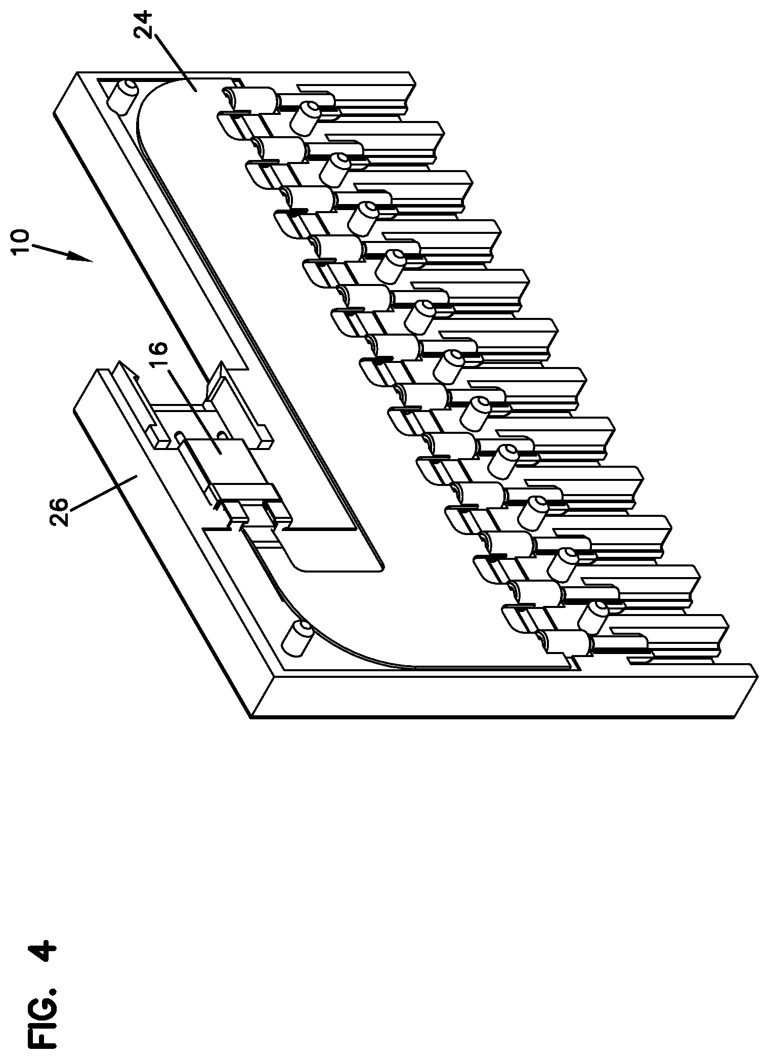
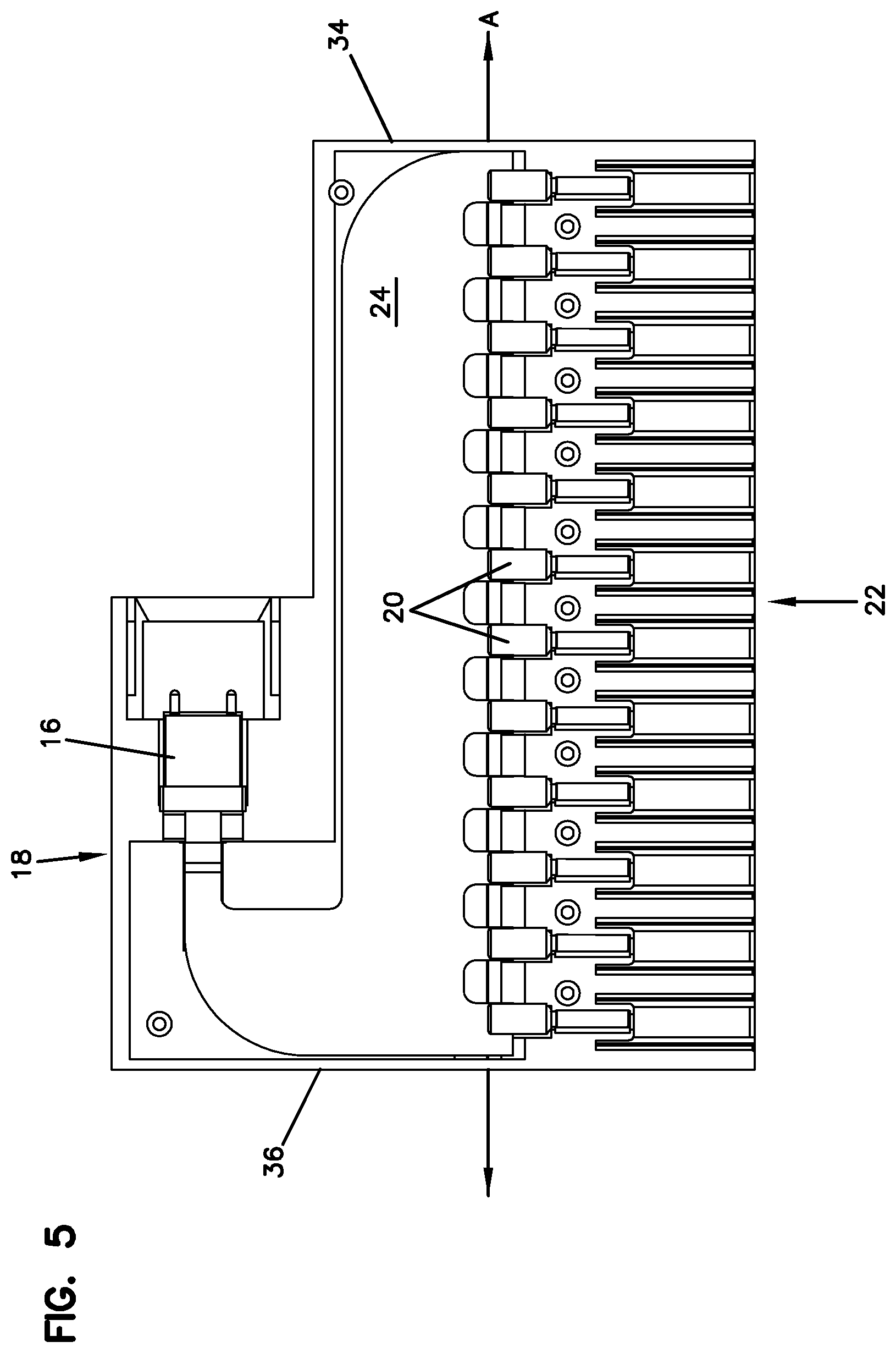
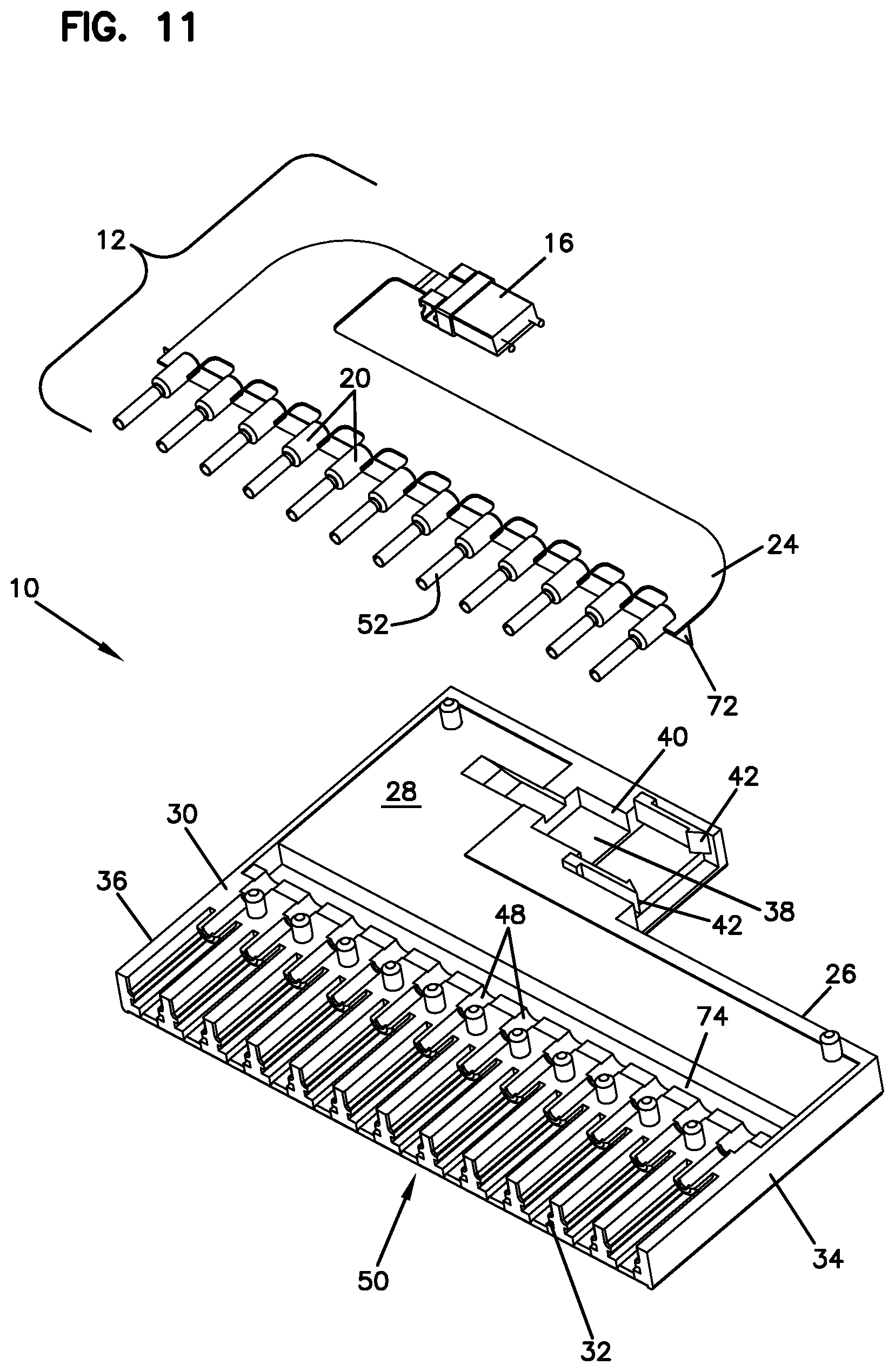
Now referring to FIGS. 1-24, a first embodiment of a fiber optic cassette 10 that utilizes a flexible optical circuit 12 is shown. In the fiber optic cassette 10 of FIGS. 1-24, the flexible optical circuit 12 is depicted as transitioning optical fibers 14 between a conventional connector 16 (e.g., an MPO connector) at the rear 18 of the cassette 10 and a plurality of non-conventional connectors 20 at the opposite front end 22 of the cassette 10, wherein portions of a substrate 24 of the flexible optical circuit 12 are physically inserted into the non-conventional connectors 20.
It should be noted that the term "non-conventional connector" may refer to a fiber optic connector that is not of a conventional type such as an LC or SC connector and one that has generally not become a recognizable standard footprint for fiber optic connectivity in the industry.
The elimination of conventional mating connectors inside the cassette 10 may significantly reduce the overall cost by eliminating the skilled labor normally associated with terminating an optical fiber to a connector, including polishing the end face of the fiber and epoxying the fiber into the connector. It further allows the fiber optic interconnect device such as the optical cassette 10 to be made very thin.
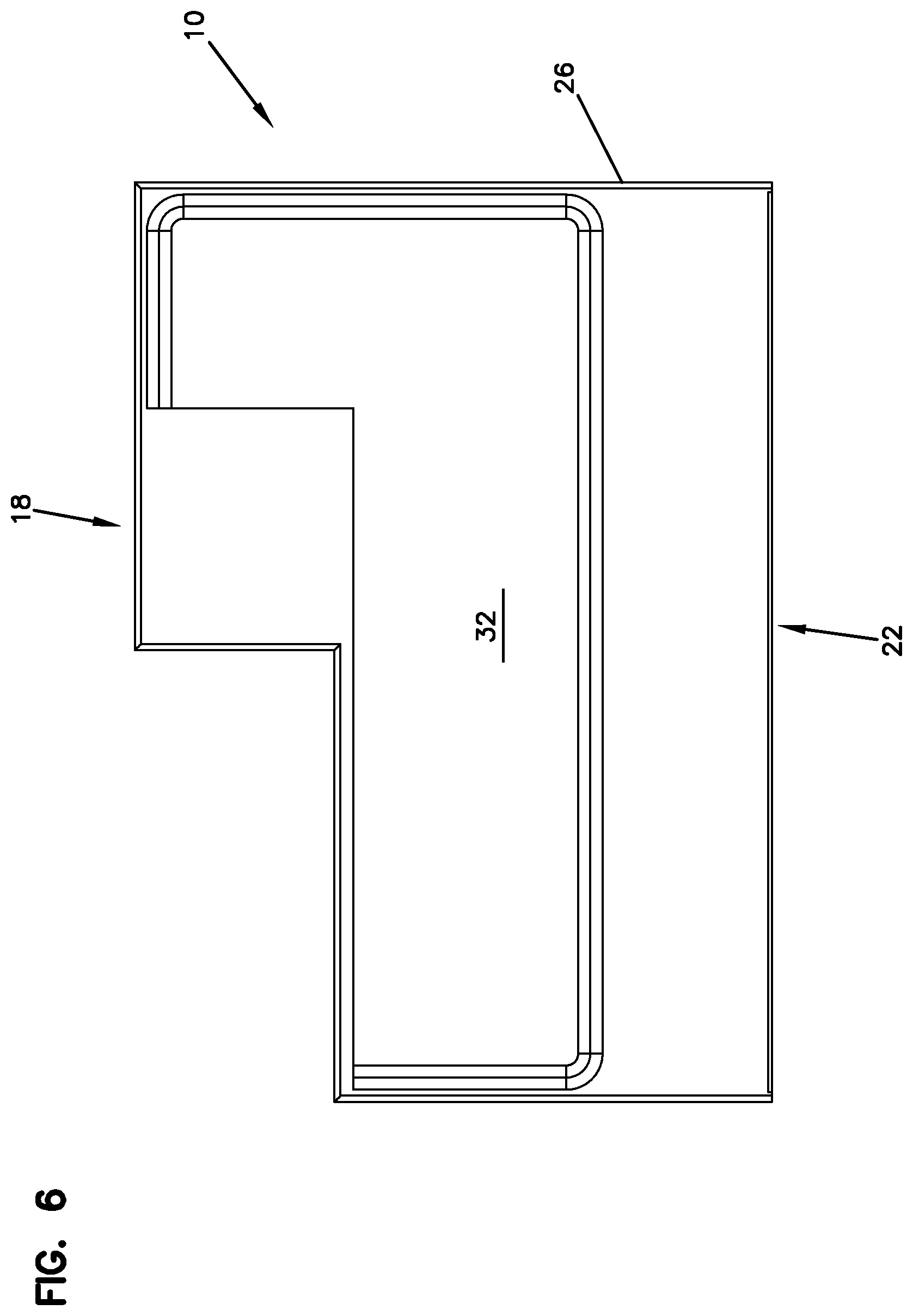
Still referring to FIGS. 1-24, the cassette 10 includes a body 26 defining the front 22, the rear 18 and an interior 28. Body 26 further includes a top 30, a bottom 32, and sides 34, 36.
A signal entry location 38 may be provided by the MPO connector 16, which in the illustrated embodiment is along the rear 18 of the cassette body 26. A pocket 40 seats the MPO connector 16 while flexible cantilever arms 42 may be provided for coupling a second mating MPO connector to the cassette 10 with a snap-fit interlock. Non-conventional connectors 20 are arranged linearly adjacent the front 22 of the cassette 10 and positioned along a longitudinal axis A defined by the body 26. In the depicted embodiment of the cassette 10, the MPO connector 16 of the cassette 10 is positioned to extend parallel to the longitudinal axis A and generally perpendicular to ferrules 44 of the non-conventional connectors 20 at the front 22 of the cassette 10.
In general, cassette 10 includes the top 30 and bottom 32 which are generally parallel to each other and define the major surfaces of cassette body 26. Sides 34, 36, front 22, and rear 18 generally define the minor sides of cassette body 26. The cassette 10 can be oriented in any position, so that the top and bottom surfaces can be reversed, or positioned vertically, or at some other orientation.
In the embodiment of the fiber optic cassette 10 shown in FIGS. 1-24, the non-conventional connectors 20 that are positioned adjacent the front 22 of the cassette 10 each defines a hub 46 mounted over the ferrule 44. A cross-section of the interface is seen in FIGS. 15 and 15A. Each ferrule 44 is configured to terminate one of the fibers 14 extending out from the flexible circuit 12, as shown in FIGS. 21-24.
The non-conventional connectors 20 are placed within pockets 48 provided at a connection block or array 50 located at the front 22 of the cassette 10. A split sleeve 52 is also provided for ferrule alignment between the hub 46 and ferrule 44 of each non-conventional connector 20 and the ferrule of another mating connector that enters the cassette 10 from the front 22.
The mating connectors entering the cassette 10 from the front 22 of the cassette 10 may be connected through fiber optic adapters that are mounted on the connection block 50. The cassette 10 of FIGS. 1-24 is shown without the rows of adapters at the front 22 of the cassette 10 that would allow conventional connectors such as LC connectors to be mated to the non-conventional connectors 20 located within the interior 28 of the cassette 10. Such adapters or adapter blocks may be snap-fit, ultrasonically welded, or otherwise attached to the rest of the cassette body 26. In the versions of the fiber optic cassettes 110, 210 illustrated in FIGS. 25-36 and 40-42, respectively, the rows of fiber optic adapters 5 are shown on the cassettes 110, 210.
In the illustrated embodiment of the cassette 10 of FIGS. 1-24, the adapters that would be used with the cassette 10 are sized to receive mating LC connectors. SC connectors can also be used with appropriate sized adapters.
The cassette 10 of FIGS. 1-24 can be sealed or can be openable, so as to allow repair, or cleaning of the inner hubs 46 and ferrules 44. In some cases, the adapter blocks can be snap fit to a rest of the body 26 for ease of assembly. Adapter blocks can also preferably be removed from a rest of the cassette 10 to allow for cleaning of the inner non-conventional connector 20. The flexible fiber optic circuit 12 allows the entire fiber bundle, including the MPO connector 16 to be able to be removed for cleaning or replacement.
Referring specifically now to FIGS. 13 and 16-24, fiber pigtails 14 extending out from a rear end 54 of the substrate 24 forming the flexible optical circuit 12 are ribbonized for termination to an MT ferrule 56 of the MPO connector 16. The fiber pigtails 14 extending out from a front end 58 of the substrate 24 are individually terminated to the ferrules 44 to be positioned at the front 22 of the cassette 10. As shown, the substrate 24 defines front extensions 60 (one per fiber 14) each provided in a spaced apart configuration for providing some flexibility to the substrate 24. The individual fibers 14 are separated out from the ribbonized section at the rear 54 of the substrate 24 and are routed through the substrate 24 to the individual front extensions 60. Each ferrule hub 46 defines a notch or a cut-out 62 for receiving front portions 64 of the front extensions 60 of the substrate 24.
Fiber pigtails 14 that extend from each of the front extensions 60 of the substrate 24 are illustrated in FIGS. 21-24 diagrammatically. Referring now to the diagrammatic views of FIGS. 21-24, according to one example embodiment, the fiber pigtails 14 extending from the substrate 24 may be defined by an optical fiber 66 that is made up of a fiber core surrounded by a cladding layer. A portion 68 of the front extension 60 of the substrate 24 forming the flexible optical circuit 12 is inserted into a cylindrical bore 70 extending through the center of the ferrule hub 46, while an exposed optical fiber 66 that is made up of the fiber core and the surrounding cladding (after the primary coating has been stripped) is inserted into the ferrule 44 (see FIG. 21). The cut-out 62 of the ferrule hub 46 receives the portion 68 of the front extension 60 of the substrate 24 in stabilizing the termination.
According to one example process step, by using a rigid substrate, when the fibers are being terminated to the ferrules 44, the ends of the fibers may be cleaved and ends of all of the ferrules 44 extending from the substrate 24 may be polished simultaneously.
As shown in FIGS. 11-13, 15, and 15A, in addition to the inherent ability of the substrate 24 of the flexible optical circuit 12 to provide a bias for the ferrules 44 of the non-conventional connectors 20 at the front 22 of the cassette 10 for ferrule interface variations, other structures may be used to supplement the inherent bias of the flexible circuit 12. For example, in the depicted embodiment of the cassette 10, a spring clip 72 is positioned within a pocket 74 in the cassette 10 and extends parallel to the longitudinal axis A of the cassette body 26. In a conventional fiber optic connector, the ferrules assemblies normally include springs such that when they are mated in an adapter, the ferrules are pressed together against the bias of the spring. In the depicted cassette 10, the spring clip 72 may be positioned to abut rear ends 75 of the ferrule hubs 46 so as provide some bias to the ferrules 44 when they are mating incoming connectors. The flexibility of the substrate 24 of the flexible optical circuit 12 allows the ferrules 44 of the non-conventional connectors 20 to flex back and the spring clip 72 provides additional bias to force them forwardly. The spring clip 72 may be adhered to the portions of the cassette 10 for rigidly fixing the spring clip 72 within the cassette 10.
It should be noted that a structure such as the spring clip 72 can be used on any of the embodiments of the fiber optic cassettes described and illustrated in the present application.
Referring now to FIGS. 25-36, another embodiment of a fiber optic cassette 110 is illustrated. The fiber optic cassette 110, similar to the cassette 10 of FIGS. 1-24, utilizes a flexible fiber optic circuit 112 within the body 126 for relaying fibers 114. In this embodiment, a multi-fiber connector 116 (in the form of an MPO connector) is oriented parallel to non-conventional connectors 120 that are at the front 122 of the cassette 110, generally perpendicular to the longitudinal axis A defined by the cassette 110. The multi-fiber connector 116 is mounted to the cassette 110 via a multi-fiber adapter 111 seated within a pocket 140 at a rear 118 of the cassette 110.
The flexible circuit 112 is configured to transition fibers 114 from the multi-fiber connector 116 at the rear 118 defining the signal entry location 138 to non-conventional connectors 120 at the front 122 of the cassette 110. The cassette 110 is shown to include multiple rows of adapters 5 in the form of an adapter block 115 at the front 122 of the cassette 110. Via the adapters 5, conventional connectors such as LC connectors may be mated with ferrules 144 of the non-conventional connectors 120 located at the front 122 of the cassette 110. The adapters 5 are arranged linearly and positioned along longitudinal axis A. In the illustrated embodiment, adapters 5 are sized to receive front LC connectors. SC connectors can also be used with appropriate sized adapters. In the illustrated embodiment, the adapters 5 are formed in a block construction 115 having a front end 117, and an opposite rear end 119. Front end 115 includes a profile for receiving LC connectors. At the rear end 119 of the adapter block 115, the ferrule assemblies of the non-conventional connectors 120 including the ferrule hubs 146 and the ferrules 144 are seated in pockets 148 aligned with ports 121 of the adapters 5. For each connector pair, a split sleeve 152 is also provided for ferrule alignment between hub and ferrule of each non-conventional connector 120 and the ferrule of a conventional LC connector.
As shown and as discussed previously, the adapter blocks 115 may be snap fit, ultrasonically welded or otherwise attached to a rest of the cassette body 126 or formed as part of the body 126. A cover 127 may be used to cover an area behind blocks 115. In FIGS. 26-31, the cassette 110 has been shown with the cover 127 removed or without the cover 127 to illustrate the internal features of the cassette 110.
As in the first embodiment of the cassette 10, the cassette 110 of FIGS. 25-36 is configured such that it can be sealed or can be openable, so as to allow repair, or cleaning of the inner hub 146 and ferrule 144. In some cases, the adapter blocks 115 can be snap fit to a rest of the body 126 for ease of assembly. Adapter blocks 115 can also preferably be removed from a rest of the cassette 110 to allow for cleaning of the inner non-conventional connector 120. The flexible fiber optic circuit 112 allows the entire fiber bundle, including the MPO connector 116 to be able to be removed for cleaning or replacement.
The termination of the fiber pigtails 114 extending from a front 158 of the substrate 124 of the flexible circuit 112 is similar to the termination for the ferrule assemblies described above with respect to the cassette 10 of FIGS. 1-24. At the rear 154 of the substrate 124, as described previously, the fibers 114 are ribbonized for termination to an MT ferrule 156.
The substrate 124 includes extensions 160 at the front side 158. The extensions 160 define cut-outs 161 between each one. The cutouts 161 allow flexibility for the substrate 124 and essentially enable the ferrules 144 of the non-conventional connectors 120 to be generally free floating structures to allow for movement in two different axes (e.g., upward/downward, front/back).
Referring specifically to FIGS. 27, 28, 31, 33, and 36, the substrate 124 of the flexible optical circuit 112 is also illustrated with a bent portion 125 adjacent the rear pocket 140 of the cassette 110. As discussed previously, one advantage of using a flexible substrate 124 to anchor the fibers 114 is to allow limited controlled movement of the substrate 124 either to accommodate any tolerance variances between the internal components and the cassette body 126 or to accommodate any movement of the internal ferrules 144 during connection to incoming connectors.
An example of a simple flexible optical circuit 312 having a substrate 324 that includes a design for controlled bending and allowing axial movement in the fibers 314 is illustrated in FIGS. 37-39. Either a U-bend or an S-bend 325 can be provided in the substrate 324 of the flexible optical circuit 312 for allowing axial movement for the fibers 314. With the tolerances of connector ferrules and molded polymeric structures (such as the cassette body), there can be a significant build up of ferrule interface variation. By allowing the substrate 324 of the flexible circuit 312 to bend in a controlled way, these tolerances can be accommodated.
FIGS. 40-42 illustrate another embodiment of a fiber optic cassette 210 utilizing a flexible optical circuit 212, wherein the bend 225 is provided generally in the middle portion 227 of the substrate 224 of the circuit 212. The substrate 224 of the cassette 210 of FIGS. 40-42 provides similar advantages as the cassettes 10, 210 described in previous embodiments.
As another example, FIGS. 43-45 illustrate a flexible circuit 412 including a substrate 424 with a twist 425 in the ribbonized-fiber part of the substrate 424. Such a design can accommodate a large distance in variation between connector interfaces. As shown in the embodiment of the flexible circuit 412 of FIGS. 43-45, the MPO connector at the rear end of the substrate may define a longitudinal axis that is perpendicular to those of the non-conventional connectors at the front of the substrate 424. Thus, the fibers 14 extending from the MPO connector may follow an "S" or "Z" shaped pathway before being terminated to the front connectors. In the depicted embodiment, the optical fibers 14 enter the substrate 424 in a side-by-side, non-overlapping configuration and branch out therefrom as they extend to the non-conventional connectors at the front of the substrate. The substrate 424 allows the fibers 14 to follow such a path while preserving any minimum bend radius requirements. In a different example embodiment that will be discussed below shown in FIGS. 51, 52, the fibers entering the substrate at the back may be oriented parallel to the portions exiting from the front of the substrate. In such an example, the fibers may enter from the rear of the substrate, again, in a non-overlapping configuration and may branch out to the different non-conventional connectors at the front of the substrate, following minimum bend radius requirements.
Referring now to FIGS. 46-50, an embodiment of a ferrule strip 500 is illustrated. One of the issues normally encountered in assembly of the cassettes (e.g., 10, 110, 210) utilizing non-conventional connectors (e.g., 20, 120) at one end of the adapter blocks (e.g., 115) is the loading of the ferrule hubs (e.g., 46, 146) onto the flex circuit (e.g., 12, 112, 212) and handling of the ferrule hubs. According to one inventive method, the ferrules (e.g., 44, 144) may be overmolded with a polymeric multi-ferrule strip 500 that forms a plurality of integral hubs 546. The multi-ferrule strip 500 can be molded to hold the ferrules 544 at the correct pitch for insertion into the pockets (e.g., 48, 148) of the cassettes (e.g., 10, 110, 210).
Now referring generally to FIGS. 51-61, when using a flexible circuit that includes a plurality of fibers embedded therein, production yield may be a big issue, especially given that all of the individual fibers have to be separately terminated into individual ferrules at the front of the flexible optical circuit. If there is any damage to one of the terminations (e.g., either to a fiber or to a ceramic ferrule), the entire flexible circuit may become unusable. The present disclosure contemplates methodologies for allowing individual retermination of the fibers if one of the optical fibers or ferrules fails.
Referring specifically now to FIGS. 51-52, according to one embodiment methodology, a looped length 613 of buffered fiber 614 may be stored within the cassette between the flexible substrate 624 and each of the non-conventional connectors 620. If one of the terminations fails, a technician would be able to unloop the length 613 of fiber 614 and reterminate, saving the rest of the flexible circuit 612.
According to another methodology, as illustrated in FIGS. 53-61, instead of utilizing a single flexible substrate for all of the fibers relayed from the multi-fiber connector 716, a plurality of separate duplex substrates 724 can be used in a stacked arrangement. Each duplex stack can be mounted removably on the cassette and may be removed for repair or replacement if one of the terminations fails.
As shown in FIGS. 53-61, according to one embodiment, there may be six duplex flex circuits 712 including six substrates 724, totaling the twelve fibers 714 coming from an MPO connector. In such an embodiment, all six of the substrates 724 may be provided by, for example, manufacturing three different shapes and then flipping the three differently shaped substrates 180 degrees to provide the six needed duplex substrates 724 for the whole stack. As shown in FIGS. 53-55, the three different shapes would be configured such that, when stacked, front extensions 760 of the substrates 724 would be spaced apart to resemble the front extensions (e.g., 60, 160) of a single integral substrate (e.g., 24, 124, 224) and to fit within the internal configuration of a given cassette.
Referring now to FIGS. 54, 54A, 55, 55A, 56, 57, 57A, 58-60, 60A, and 61, since the portion of the fibers 714 that are to be terminated to the MT ferrule of an MPO connector have to be provided in a flat, ribbonized configuration for the termination and since the stacked flex circuits 712 have the fibers 714 in a stepped configuration, a clamp structure 780 that acts as a fiber transition device may be used within the cassette 712.
As shown in FIGS. 54, 54, 54A, 55, 55A, 56, 57, 57A, 58-60, 60A, and 61, the clamp structure 780 may include an upper member 782 that is snap fit to a lower member 784 with cantilever arms 786 that have tapered tabs 788. Both the upper and the lower members 782, 784 of the clamp structure 780 provide a fiber channel/guide 790 that includes steps 792 for transitioning the fibers 714 from a stepped configuration to a flat configuration for terminating to the MT ferrule 756 of an MPO connector 716. The clamp 780 is designed such that stacked flex fibers 714 are converted to a linear plane so they can be ribbonized while maintaining the minimum bend radius requirements of the fibers 714. The upper and lower members 782, 784 of the clamp structure 780 removably snap together for both holding the stacked substrates 724 in position and for controlling the transition of the fibers 714 while supporting bend radius limitations. If any of the flex substrates, the ferrules, or the fibers is damaged, the clamp structure 780 can be taken apart, removing the flex substrate 724 to be repaired or replaced.
According to certain embodiments, any of the cassettes described above and illustrated herein may have a length of 3 to 4 inches (parallel to the longitudinal direction A), a width of 2 to 3 inches (front to back), and a height of approximately 1/2 inch. More preferably, the length may be 3 to 31/2 inches, the width may be 2 to 21/2 inches, and the height may be 1/2 inch. The height can vary as needed, such as to accommodate different formats of adapters 5 or multiple rows of adapters 5.
Referring now to FIGS. 62-66, another example method for terminating a fiber pigtail 814 extending out from a front end 858 of a flex substrate 824 to a ferrule of a non-conventional connector is illustrated. In the depicted embodiment, duplex flex circuits 812 similar to flex circuits 712 discussed above are used to illustrate the example termination method. As shown in FIG. 62, such duplex circuits 812 are provided in a stacked arrangement when being placed into a cassette body. According to the embodiment shown in FIGS. 62-66, the pigtails 814 that are to be individually terminated to ferrules 844 are formed by stripping a portion of the flex substrate 824 (including a primary coating layer of the fiber) such that an optical fiber 866 formed from a combination of a fiber core and a cladding layer is left. In certain embodiments, the optical fiber 866 formed from the fiber core and the cladding layer may be 125 micron in cross-dimension. The primary coating layer that is stripped is generally around 250 micron in cross-dimension according to one embodiment. The optical fiber 866 extends from a portion 868 of a front extension 860 of the flex substrate 824 that is to be inserted into the ferrule hub 846. According to certain embodiments, portion 868 defines a generally square cross-sectional shape having side dimensions of 0.5 mm each. Thus, the square cross-sectional portion 868 is able to be inserted into a cylindrical bore 870 extending through the center of a ferrule hub 846, which may be about 0.9 mm in diameter (see FIGS. 63-66). The exposed optical fiber 866 that is made up of the fiber core and the surrounding cladding (after the primary coating has been stripped) is inserted into the ferrule 844, as seen in FIGS. 64-66.
Now referring to FIGS. 67-73, an example of a cassette 810 that is configured for receiving stacked flex circuits such as the flex circuits 812 shown in FIGS. 62-66 is illustrated. The cassette 810 is similar in certain aspects to the cassettes 10, 110, and 210 shown in previous embodiments. However, the cassette 810 defines pockets 848 at the front end 822 of the cassette body that match the exterior shape of the ferrule hubs 846 (e.g., having hexagonal footprints), wherein the pockets 848 are configured to fully surround the ferrule hubs 846. The pockets 848 are formed from portions of the cassette body that are integrally formed with the adapter block 815 of the cassette 810. As shown, the adapter block 815 is removably inserted into the cassette body 826. The pockets 848, also having a hexagonal configuration, match the exterior shape of the ferrule hubs 846 and prevent rotation of the hubs therewithin. In this manner, the hubs are retained in a stable manner during termination, assembly, polishing, etc.
Even though the ferrule hubs 846 and the matching pockets 848 have been illustrated with a hexagonal cross-section in the depicted embodiment, in other embodiments, the keying mechanism can be provided using different cross-sectional shapes having flat portions (such as square, rectangular, etc.). For example, an embodiment of a ferrule usable with the cassettes of the present disclosure having squared ferrule hubs has been shown in FIGS. 53-57 and 60.
As shown, the cassette body 826 defines pockets 840 for receiving a clamp structure 880 (similar to the clamp structure 780 of FIGS. 56-61) and an MPO connector 816 that is terminated to the rear ends of the individual duplex flex substrates 824.
Still referring to FIGS. 67-73, the embodiment of the cassette 810 used with the stacked duplex flex circuits 812 has been illustrated with further additional aspect that may be used on the cassettes (e.g., 10, 110, 210) of the earlier embodiments. For example, in accordance with some aspects, certain types of adapters that form the adapter blocks at the fronts of the cassettes may be configured to collect physical layer information from one or more fiber optic connectors (e.g., LC connectors) received thereat. Certain types of adapters may include a body configured to hold one or more media reading interfaces that are configured to engage memory contacts on the fiber optic connectors. The one or more media reading interfaces may be positioned in each adapter body in different ways. In certain implementations, the adapter body may define slots extending between an exterior of the adapter body and an internal passage in which the ferrules of the connectors are received. Certain types of media reading interfaces may include one or more contact members that are positioned in such slots. A portion of each contact member may extend into a respective one of the passages to engage memory contacts on a fiber optic connector.
In the depicted example of the cassette 810 of FIGS. 67-73, the contacts 801 that extend into each of the adapter passages of the block 815 are on a removable structure. The contacts 801 are defined on a printed circuit board 803 that is placed between the flexible circuits 812 and the cover 827 of the cassette 810. The contacts 801 align with the top sides of the adapter passages and extend into the adapter passages so as to engage memory contacts of fiber optic connectors inserted into the adapter passages. The printed circuit board 803 is designed to relay the electrical signals from the contacts 801 at the front of the cassette 810 to the rear of the cassette 810 as shown in FIGS. 67-73. A conductive path may be defined by the printed circuit board 803 between the contacts 801 of the adapters at the front end with a master circuit board. The master circuit board may include or connect (e.g., over a network) to a processing unit that is configured to manage physical layer information obtained by the media reading interfaces. FIG. 73 illustrates a fiber optic connector making electrical contact with the media reading interfaces 801 of the printed circuit board 803 of the cassette 810.
Example adapters having media reading interfaces and example fiber optic connectors having suitable memory storage and memory contacts are shown in U.S. Patent Publication No. 2011/0262077, the disclosure of which is hereby incorporated herein by reference.
In addition to the various uses and applications of the described cassettes, the cassettes can be used to terminate the fibers of a multi-fiber FOT cable, such as a 144-fiber cable, to make installation of the terminated cables easier and faster.
One advantage of the disclosed cassettes is that handling in the field of individual connectors, MPO connectors, or fanouts with upjackets are eliminated. The dimensions of the cassettes 10, 110, 210, 810 may be reduced by using flexible substrates (e.g., 24, 124, 224, 824) that allow optimization of the bend radius limits of the fibers by fixing the fibers in a given footprint or pattern. Also, manual handling and termination of individual fibers within the cassettes is reduced or eliminated, wherein automated, repeatable terminations may be provided within the cassettes.
The cassettes described and illustrated herein may be used by being mounted to different types of telecommunications fixtures. The cassettes of the present disclosure may be fixedly mounted or mounted, for example, as part of slidably movable modules or packs.
Although in the foregoing description, terms such as "top", "bottom", "front", "back", "right", "left", "upper", and "lower were used for ease of description and illustration, no restriction is intended by such use of the terms. The telecommunications devices described herein can be used in any orientation, depending upon the desired application.
Having described the preferred aspects and embodiments of the present disclosure, modifications and equivalents of the disclosed concepts may readily occur to one skilled in the art. However, it is intended that such modifications and equivalents be included within the scope of the claims which are appended hereto.
The above examples include flexible optical circuits connecting a multi-fiber (MPO) connector to individual fiber connectors. FIGS. 74-85 show various examples of multi-fiber connector (MPO) to multi-fiber connector (MPO) connections with a flexible optical circuit.
Twelve fiber connectors are known (including a single row or multiple rows of twelve fibers (for example, 2-6 rows)). Some examples use the twelve fiber connectors, but not all fibers are signal/light carrying. These fibers are dark or unused but still part of the flexible foil. Such a construction enables ease of assembly by connecting all twelve (or multiples of twelve) fibers at the same time. If the unused fibers were not present, there is a chance the multi-fiber ferrule could become damaged during polishing if open bores were present through the ferrule.
Multiple layers of flexible foil can be used as desired with one or more multi-fiber connectors to improve ease of assembly and fiber management.
FIGS. 74-85 show various examples of flexible foils and multi-fiber connectors. The foils can be housed in cassettes where the connectors are connected to adapters as part of the cassettes. The foils can be used in other equipment without being housed in a cassette.
The foils are easier to handle during assembly since the fibers are handled as a group (or subgroup). To terminate to a connector 16, the substrate is removed as is the fiber coating, then the glass fibers are connected to the ferrule of the multi-fiber connector 16 in a traditional manner, such as with epoxy.
Referring to FIGS. 74-76, the flex foil is shown with multiple connectors 16 connected to various fibers organized and supported by the foil. In the example shown, not all of the fibers provided carry signals. Specifically, on the side of the foil with three connectors 16, only eight of the twelve fibers carry signals, and the middle four, are dark fibers.
Referring now to FIGS. 77-83, various examples of foils and connectors are shown with different routings. In some cases, the fibers are inactive, or dark. In some applications, these fibers can be used for carrying other signals.
In FIG. 77, foil variants are shown where the connector rows terminate to different foils. A top row terminates to a top foil, and a bottom row terminates to a bottom foil. The foils could have different origins.
In FIG. 78, foil variants are shown where the connector rows terminate to different foils. A row is shared between foils. There could be more than two foils.
In FIG. 79, foil variants are shown where the connector rows terminate to different foils. The mating plug can be selectively loaded.
In FIG. 80, foil variants are shown where the fibers are distributed between connectors not parallel to each other, such as when external access is restricted.
In FIG. 81, foil variants are shown where some fibers are passed through, and other fibers are looped back to the top row and out of the plug. Fibers come in on the bottom row. For example, eight fibers are looped out, and four fibers are passed to far end, used for instance to drop a subset of fibers of a larger fiber count trunk to an individual cabinet or device, may be in a daisy-chain fashion down a cabinet row.
In FIG. 82, foil variants are shown where some fibers are passed through, and other fibers are looped back to the top row and out of the plug. Fibers come in on the bottom row. For example, eight fibers are looped out, and four fibers are passed to an individual cabinet or device.
In FIG. 83, foil variants are shown where the connector rows terminate to different foils. In this case, there can be mixing a 40 Gig Ethernet channel and four control fibers from different sources, or fibers that can be used to test continuity of a channel, discover where the far end goes, give visual illumination of a desired connector end using colored light to speed location of a connector in a panel or warn a user if the wrong connector is unplugged.
Referring now to FIGS. 84 and 85, a further embodiment of the cable arrangement of FIGS. 74-76 is shown wherein twelve fiber connectors 16 are used at each end of the cable assembly, and each connector is terminated with twelve fibers. However, for the cable assembly end with three connectors, each connector has four dark fibers. As shown, the end of the cable assembly with two connectors shares fibers from two different connectors from the end with the three connectors. See also FIGS. 74-76.
It is to be appreciated that there could be branching devices such as optical couplers or WDMs (Wavelength Division Multiplexers) within the flex circuit. This enables signal distribution and/or monitoring of circuits for presence of signal, and signal quality, for example.
* * * * *
D00000
D00001
D00002
D00003
D00004
D00005
D00006
D00007
D00008
D00009
D00010
D00011
D00012

D00013

D00014

D00015

D00016

D00017

D00018

D00019

D00020

D00021
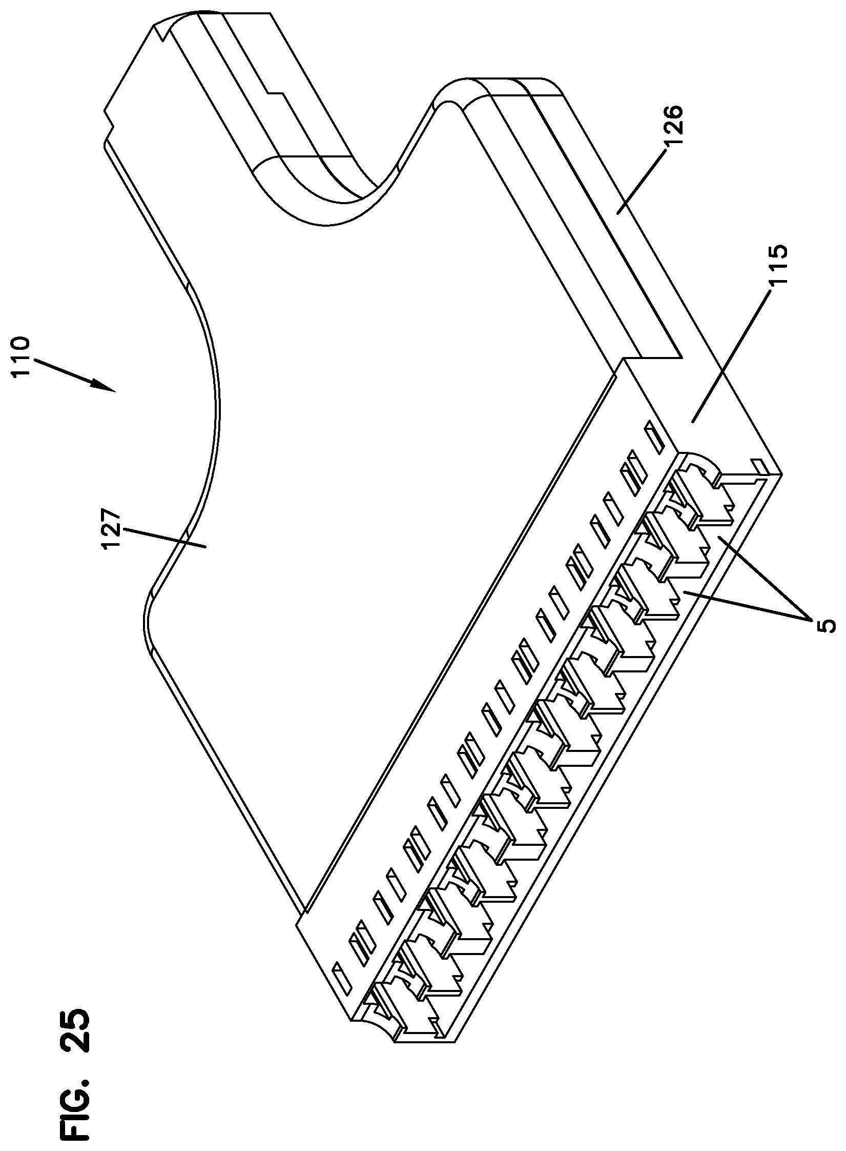
D00022

D00023
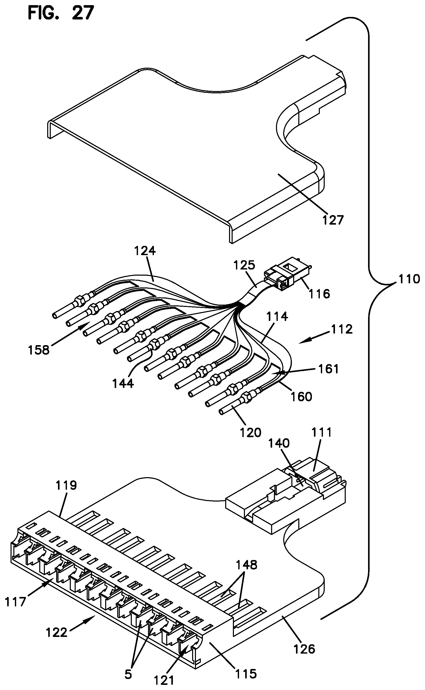
D00024

D00025

D00026
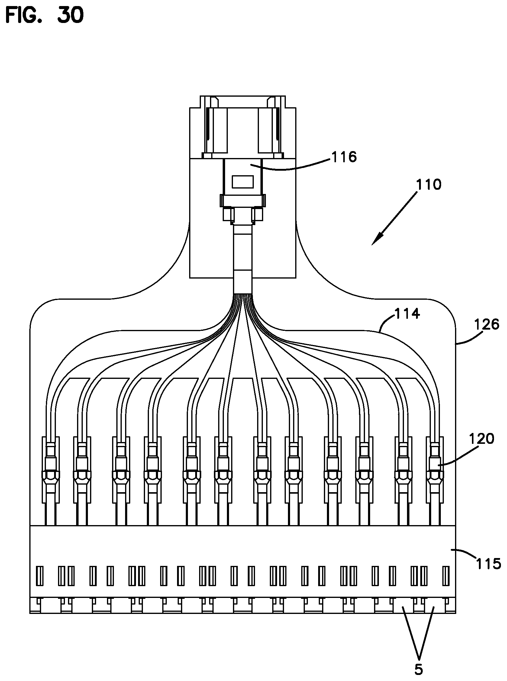
D00027
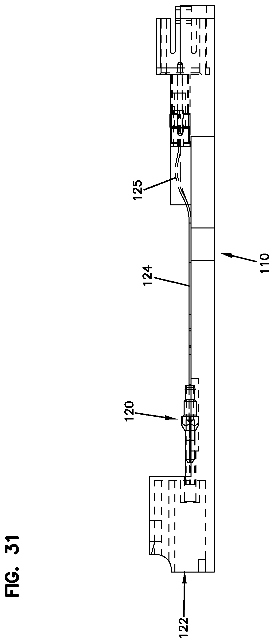
D00028
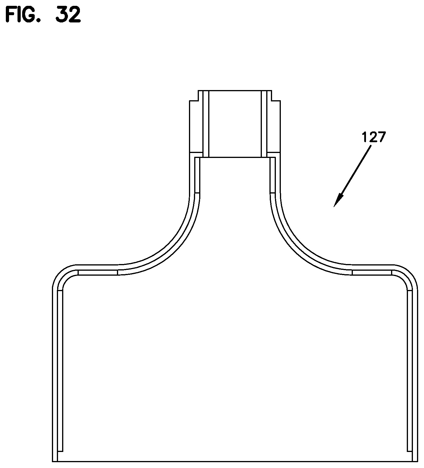
D00029
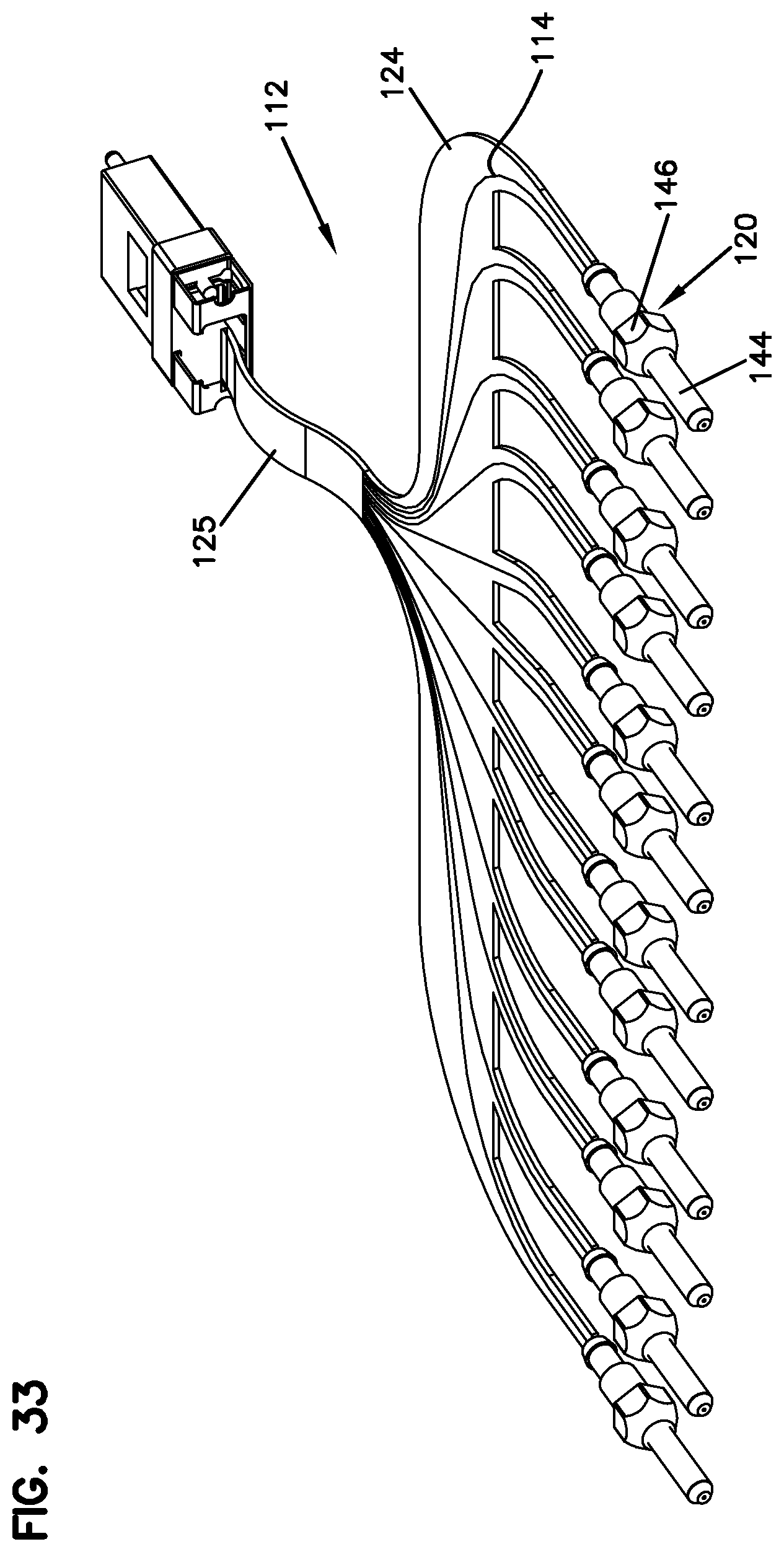
D00030

D00031
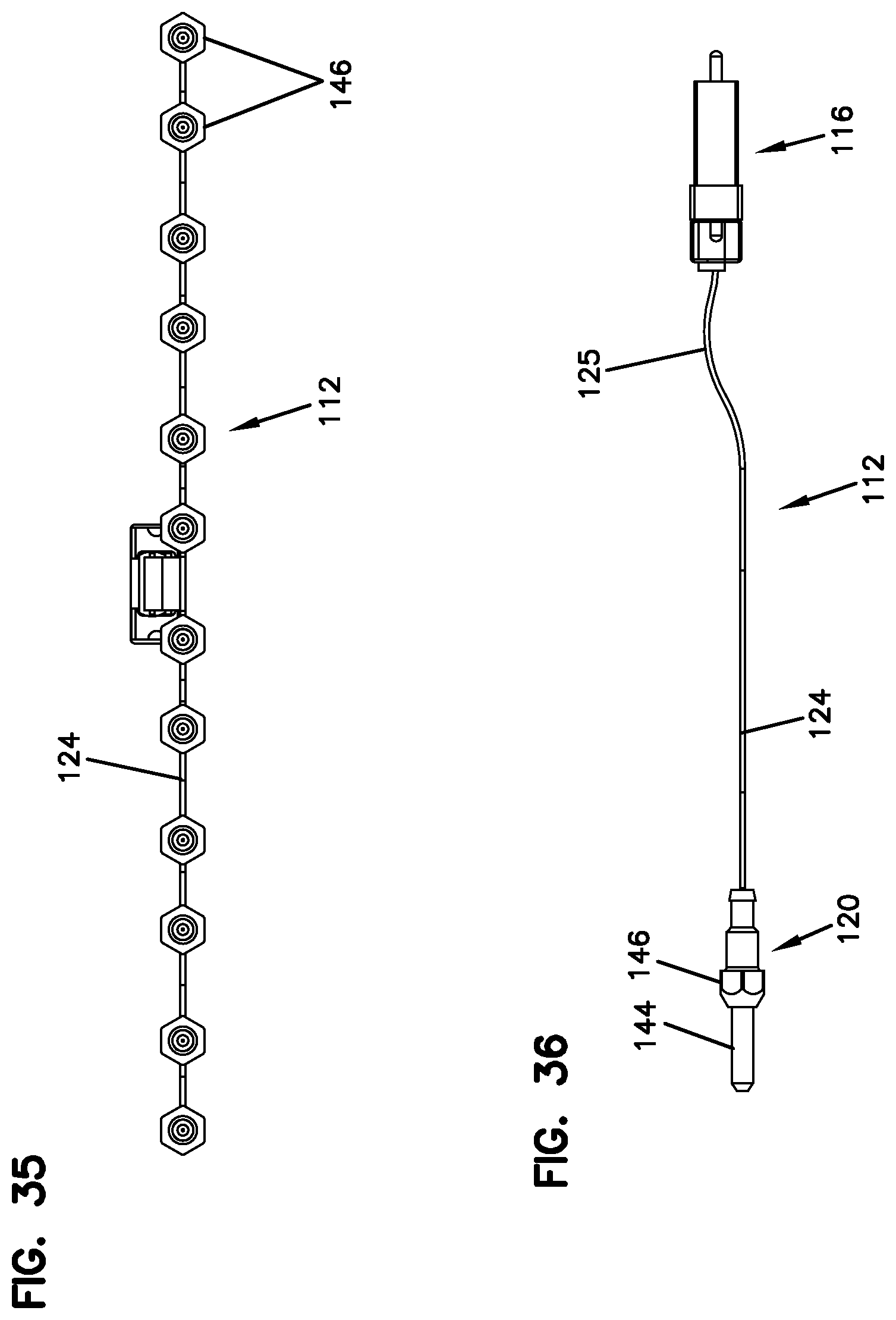
D00032

D00033

D00034

D00035

D00036
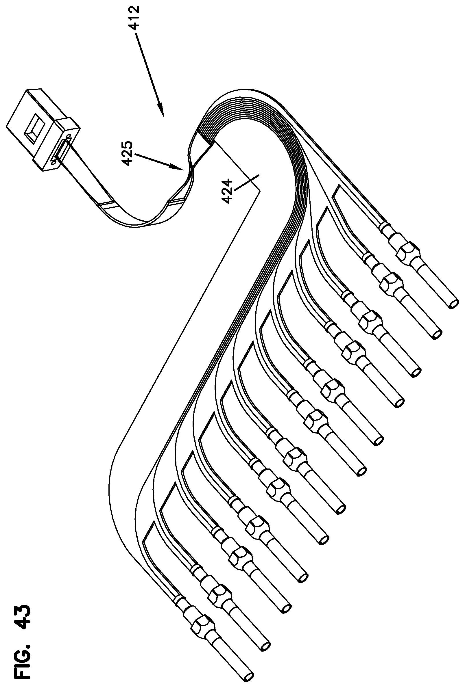
D00037
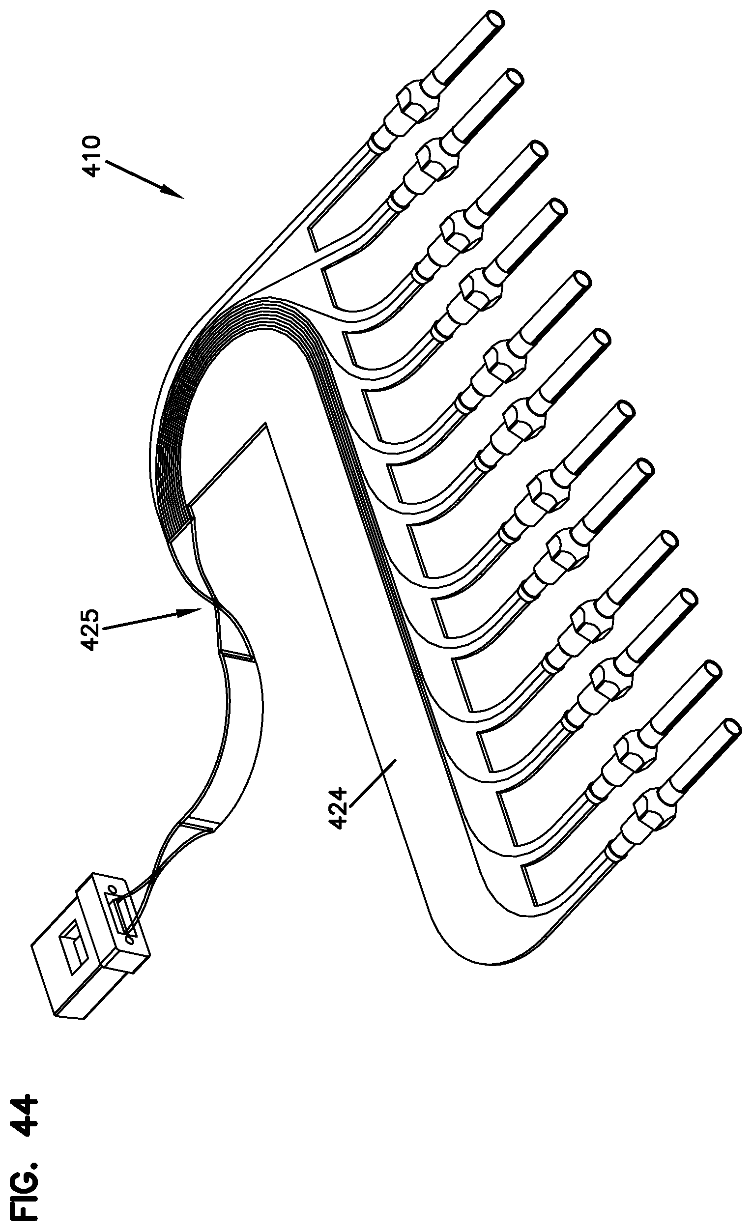
D00038

D00039

D00040

D00041

D00042
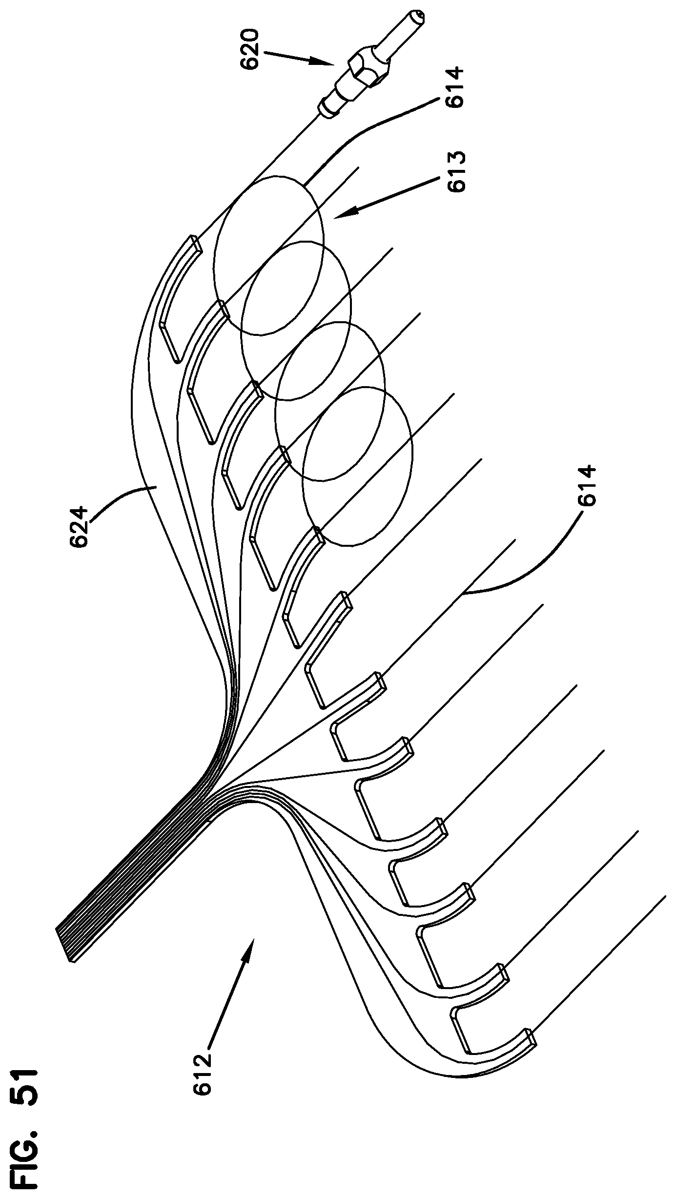
D00043
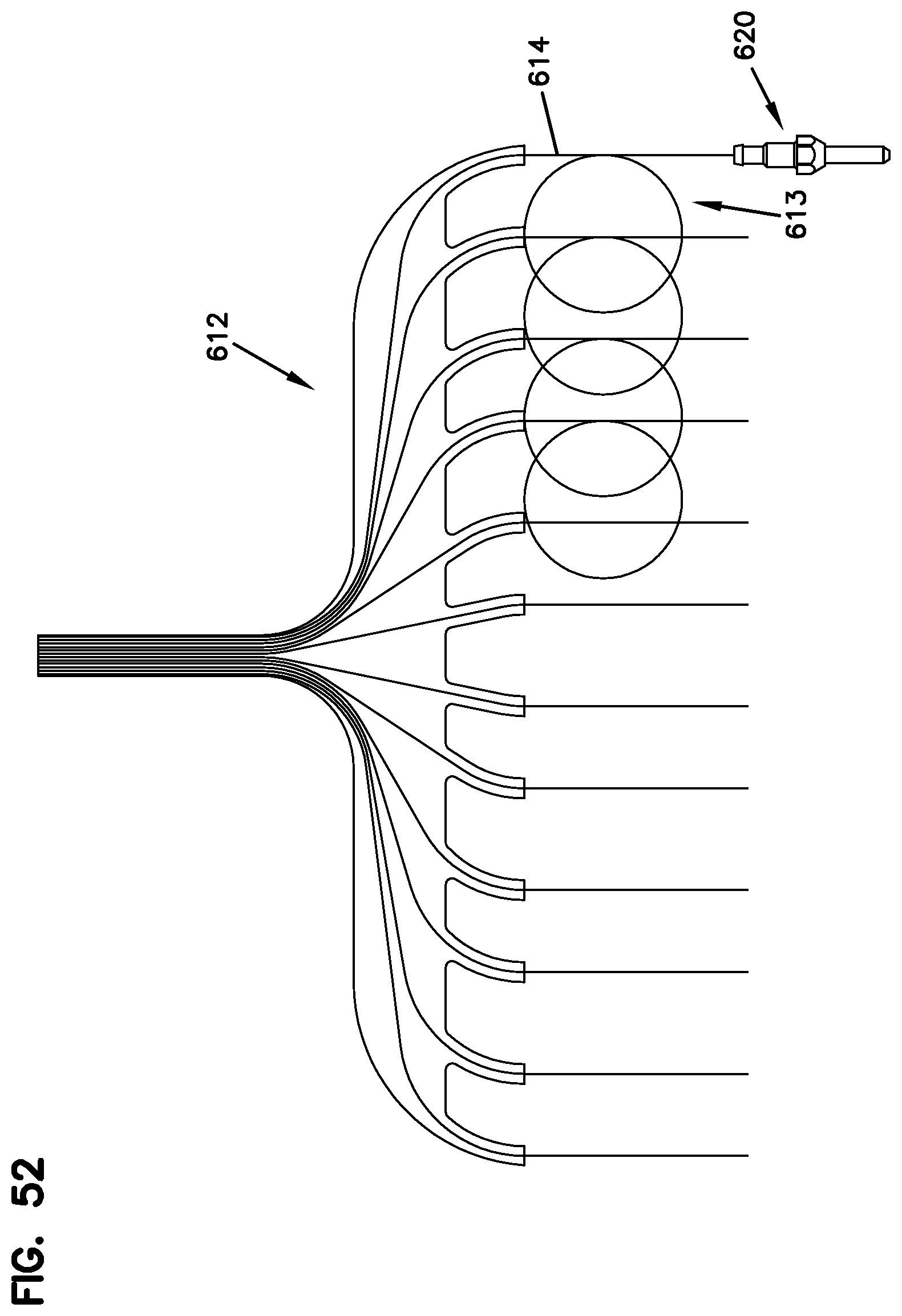
D00044
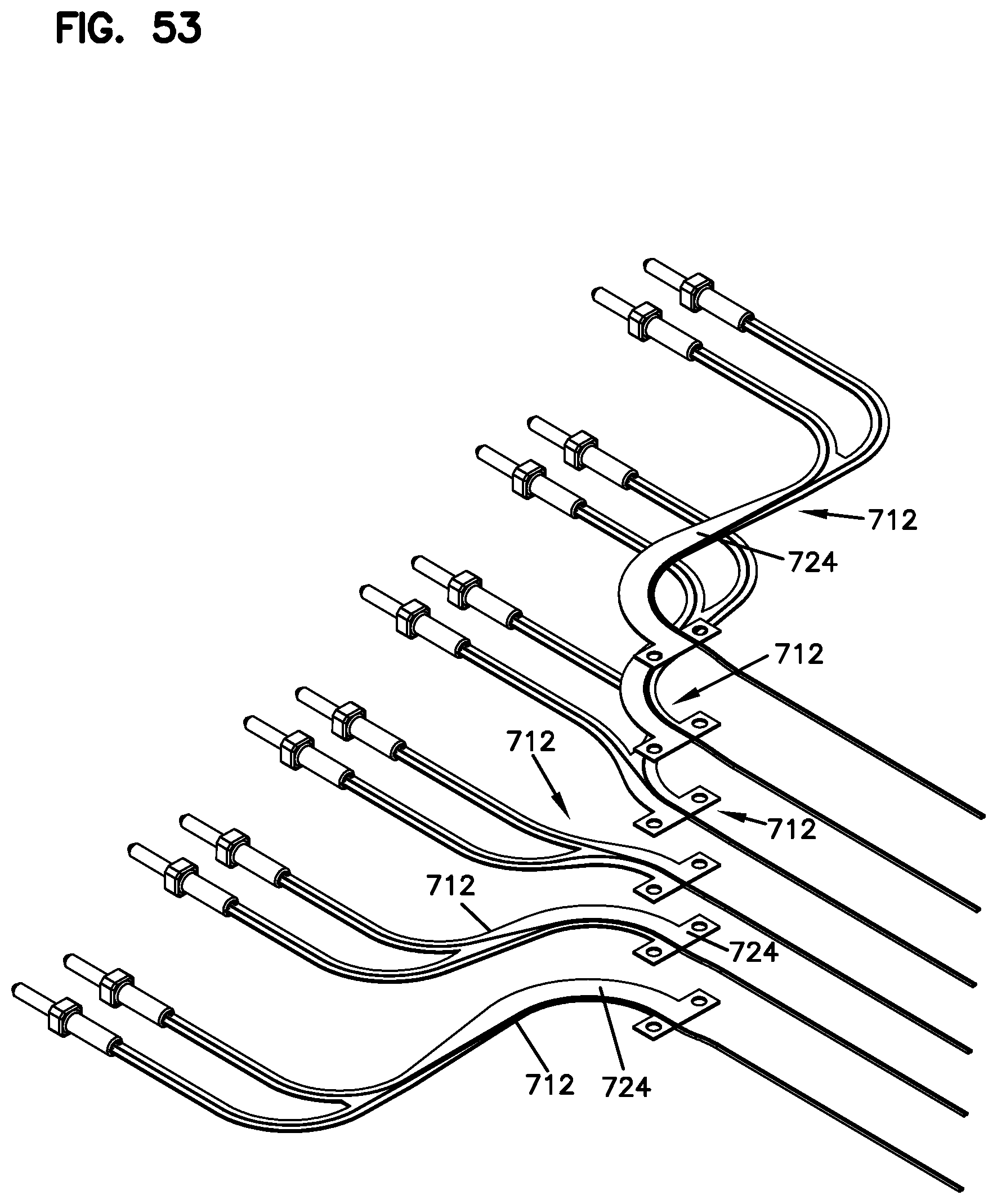
D00045

D00046
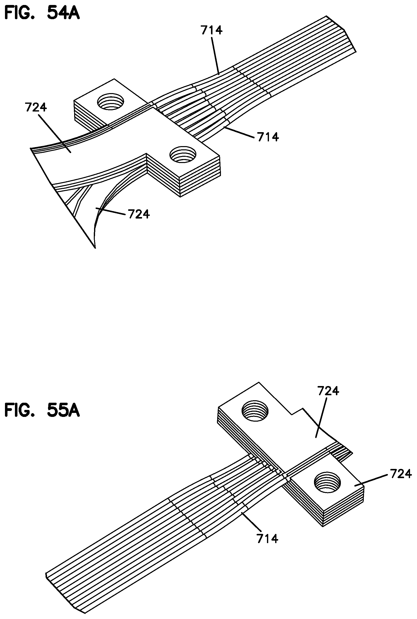
D00047

D00048
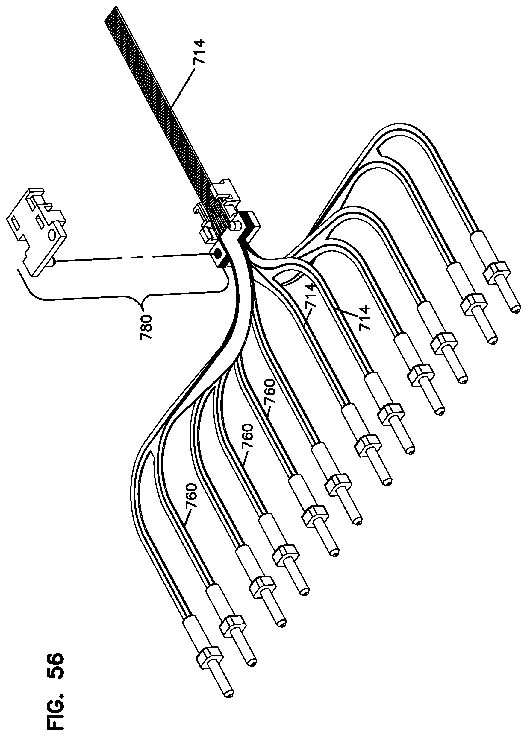
D00049

D00050
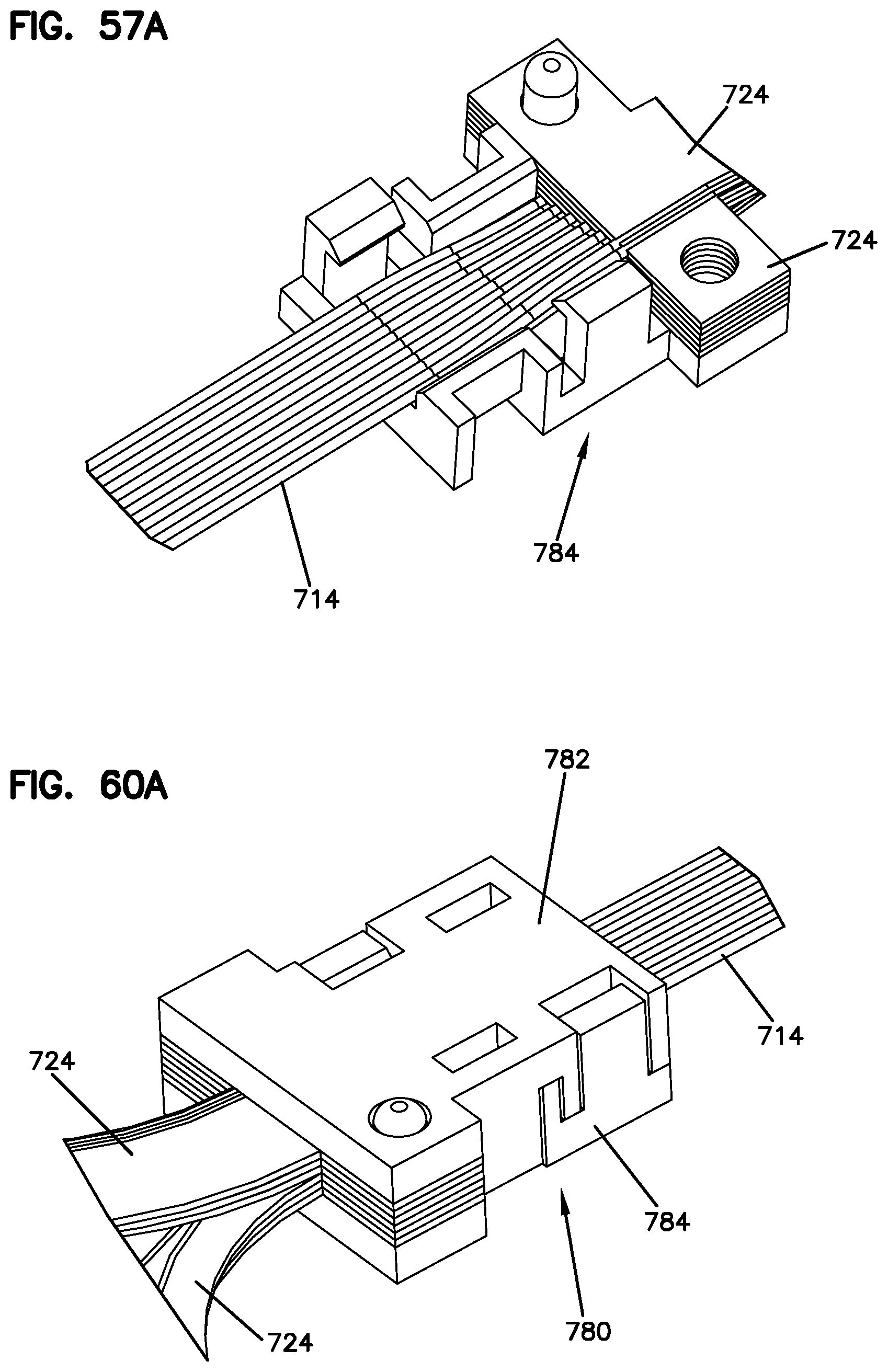
D00051

D00052

D00053

D00054
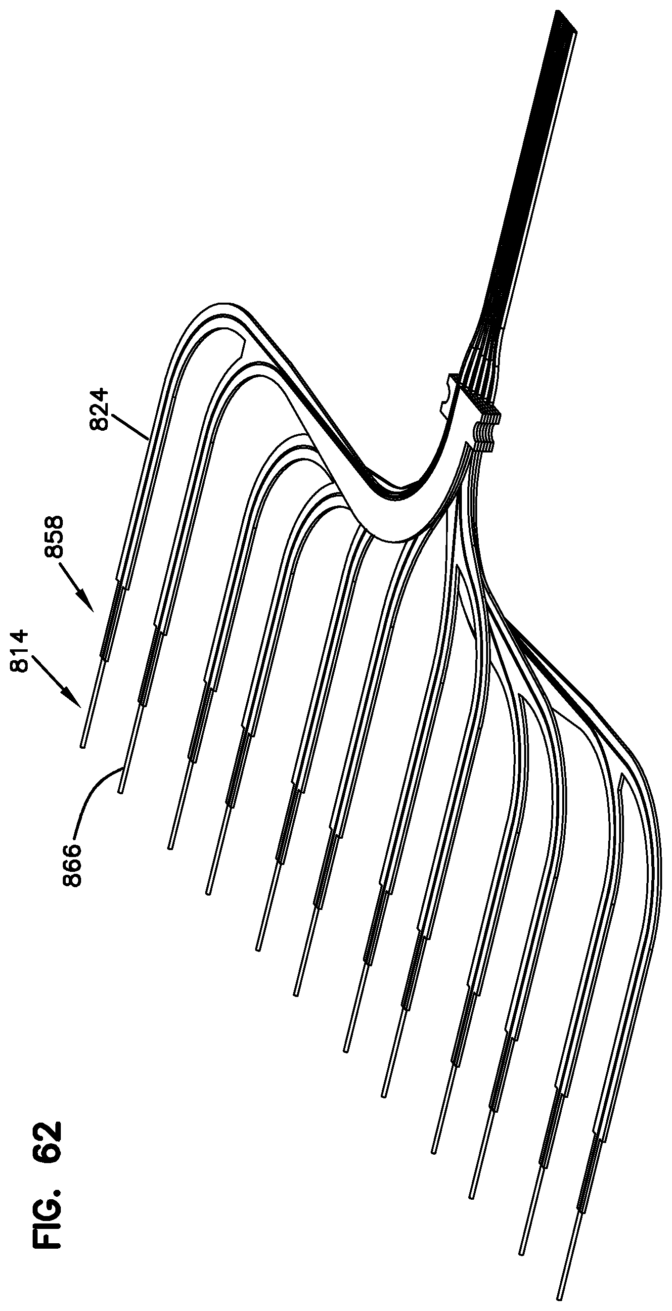
D00055

D00056

D00057
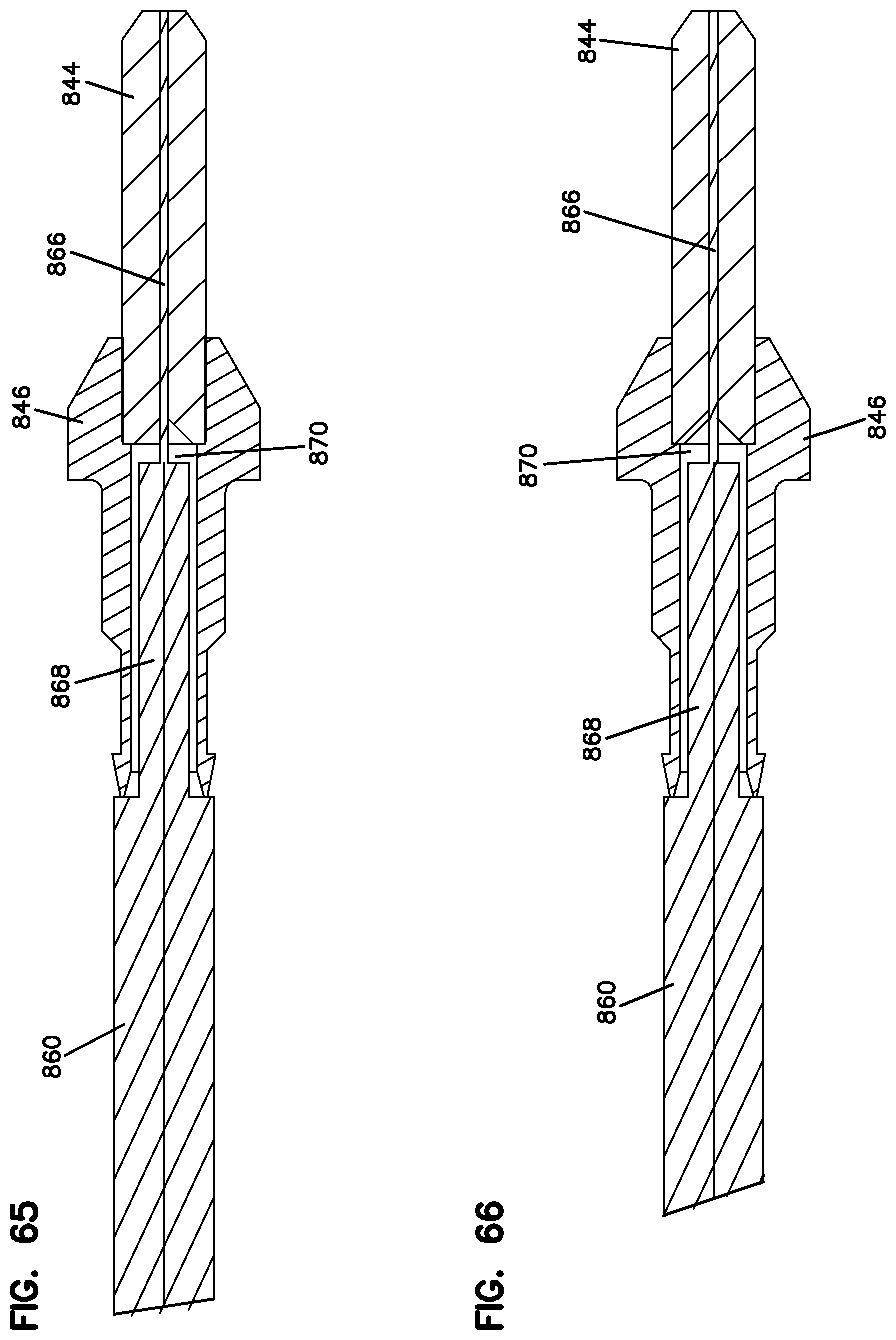
D00058
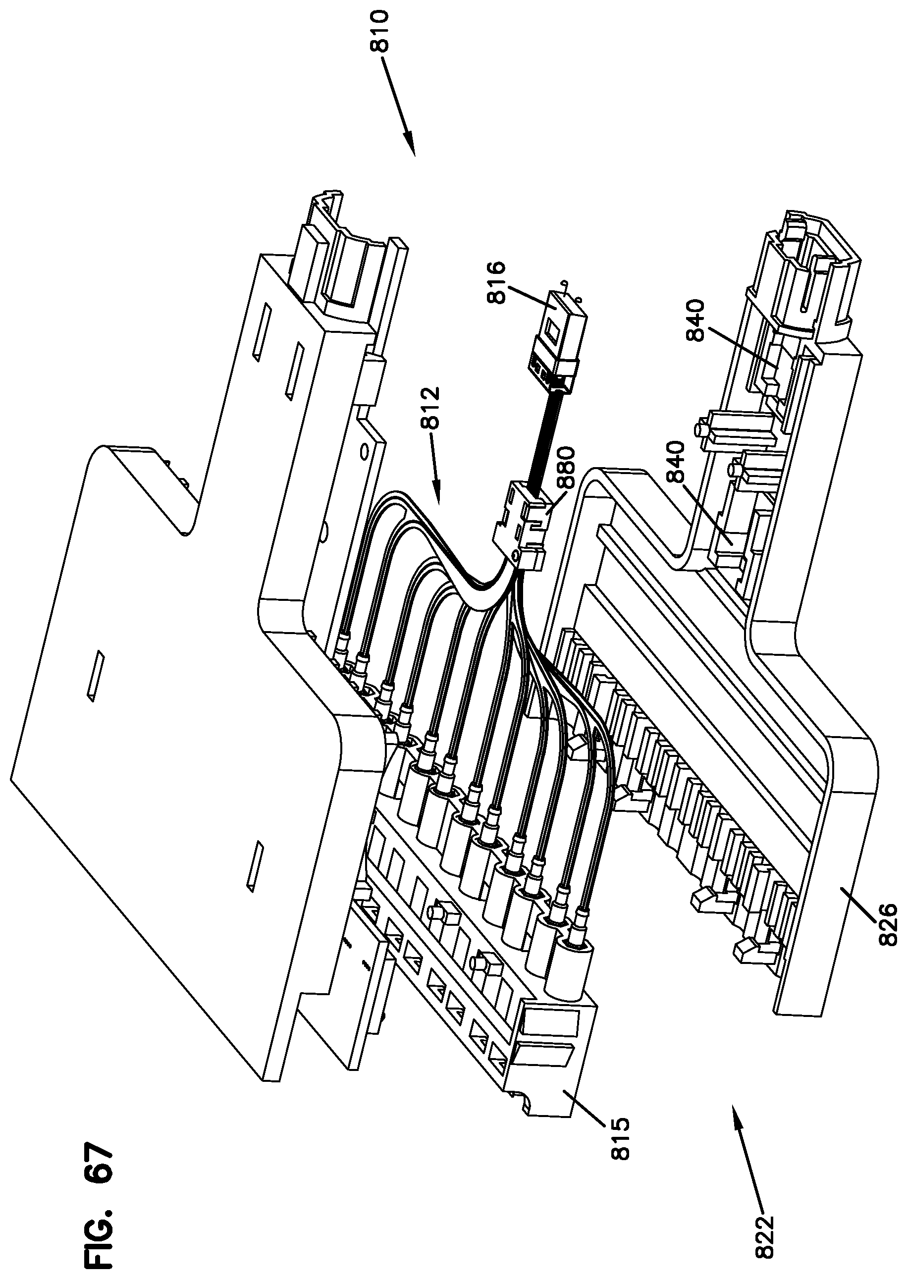
D00059

D00060
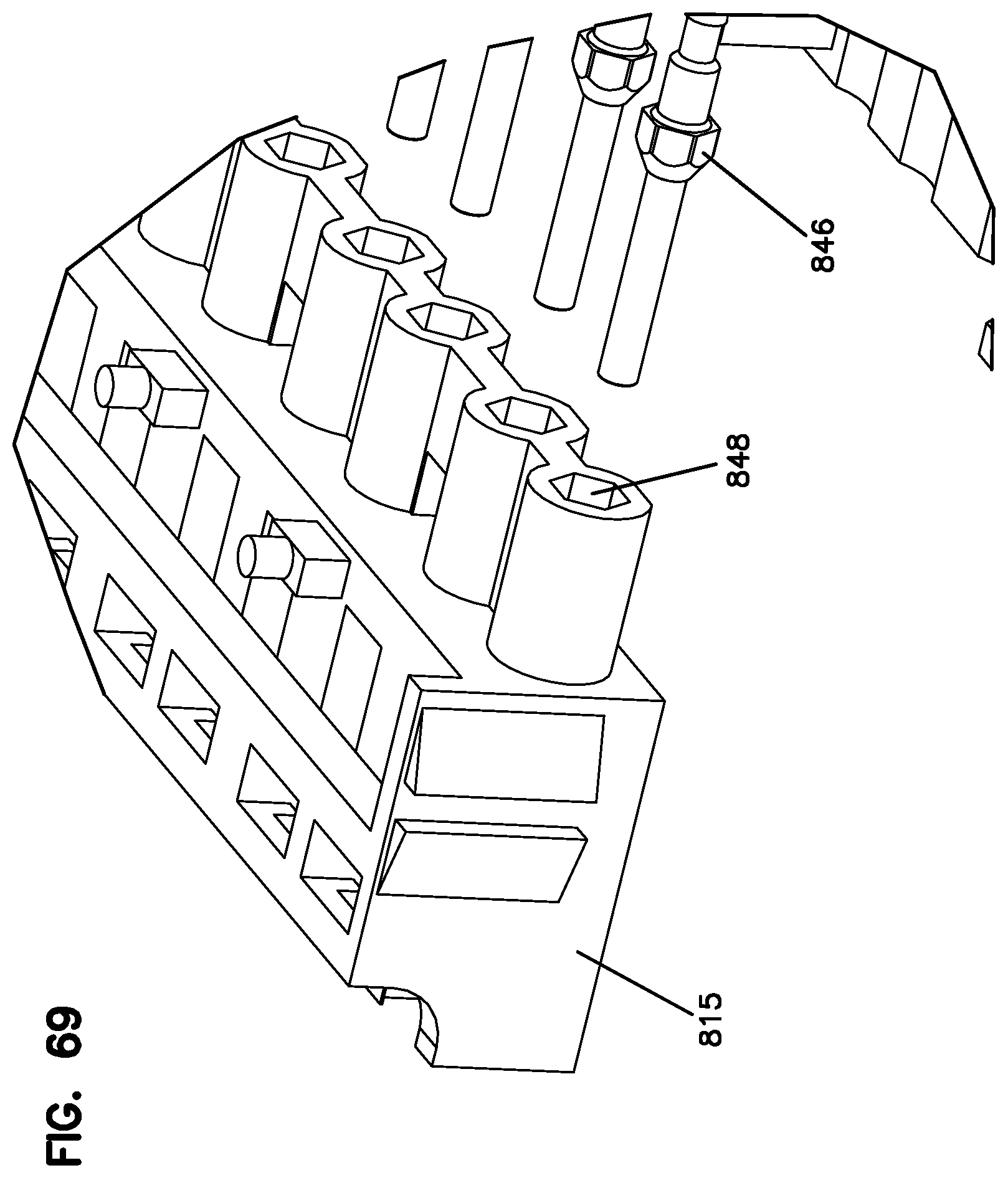
D00061
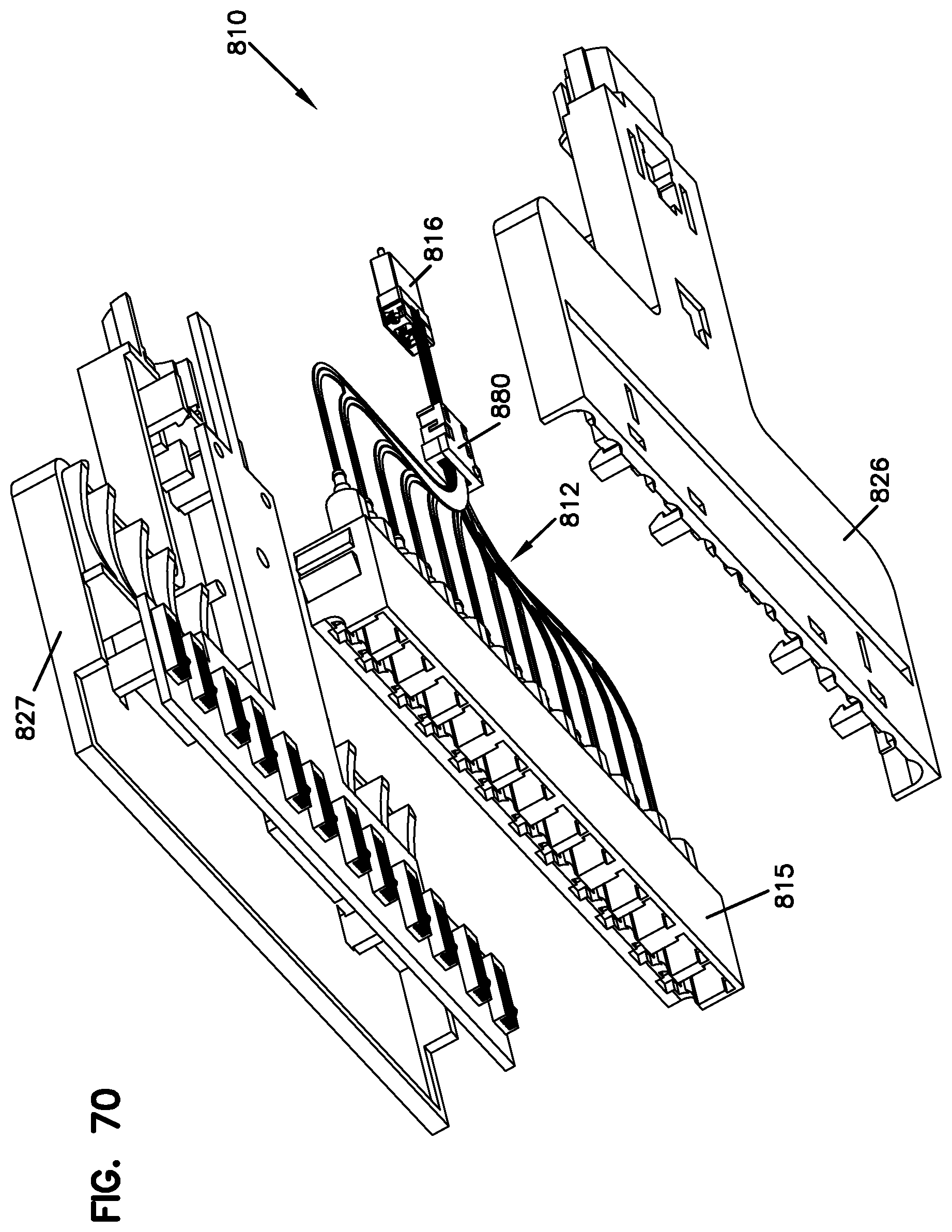
D00062

D00063

D00064

D00065
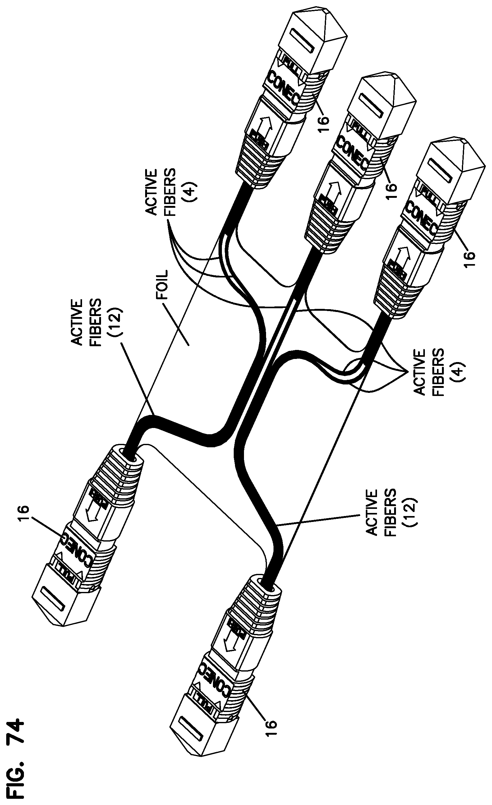
D00066

D00067

D00068

D00069

D00070

D00071

D00072

D00073
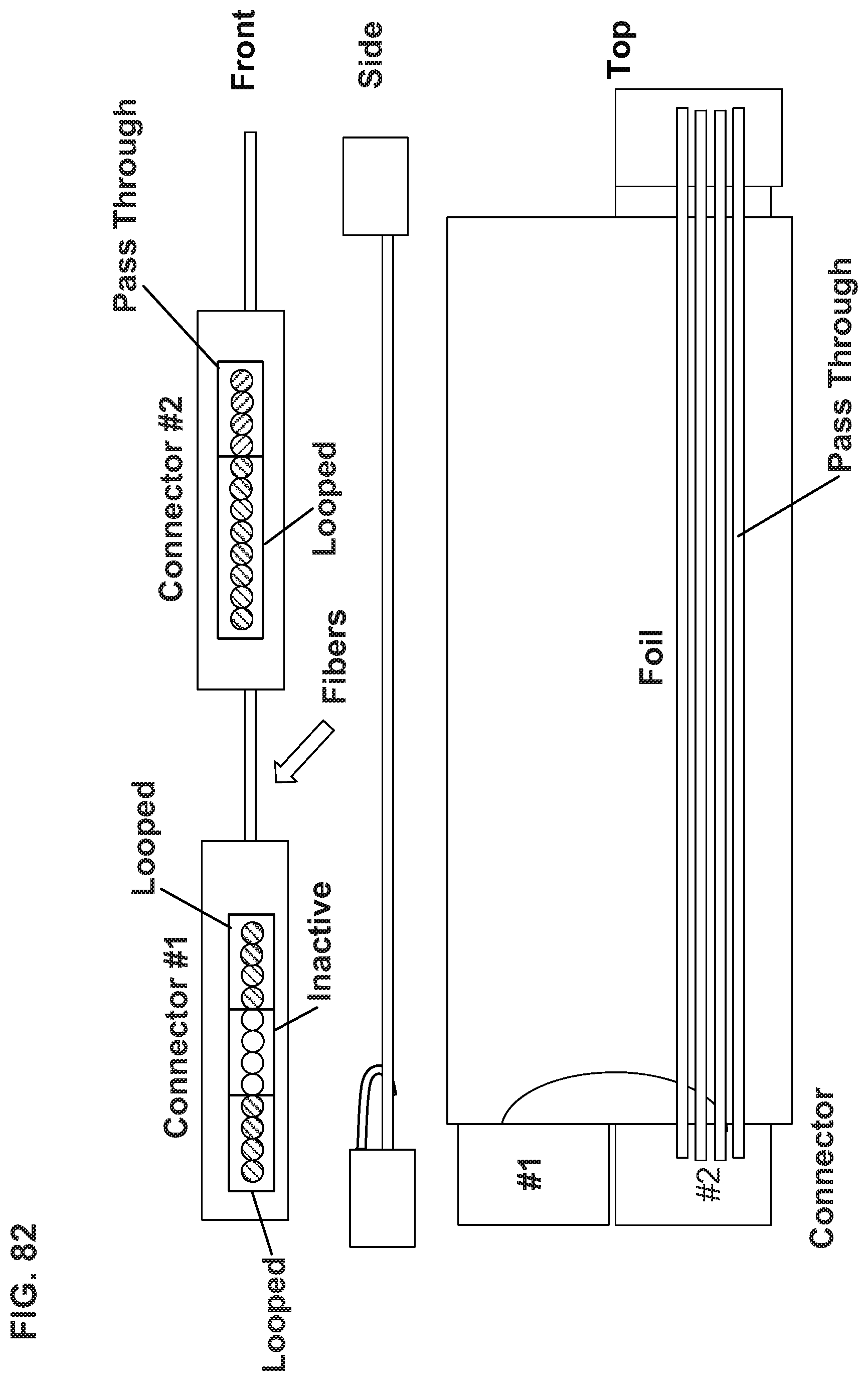
D00074

D00075
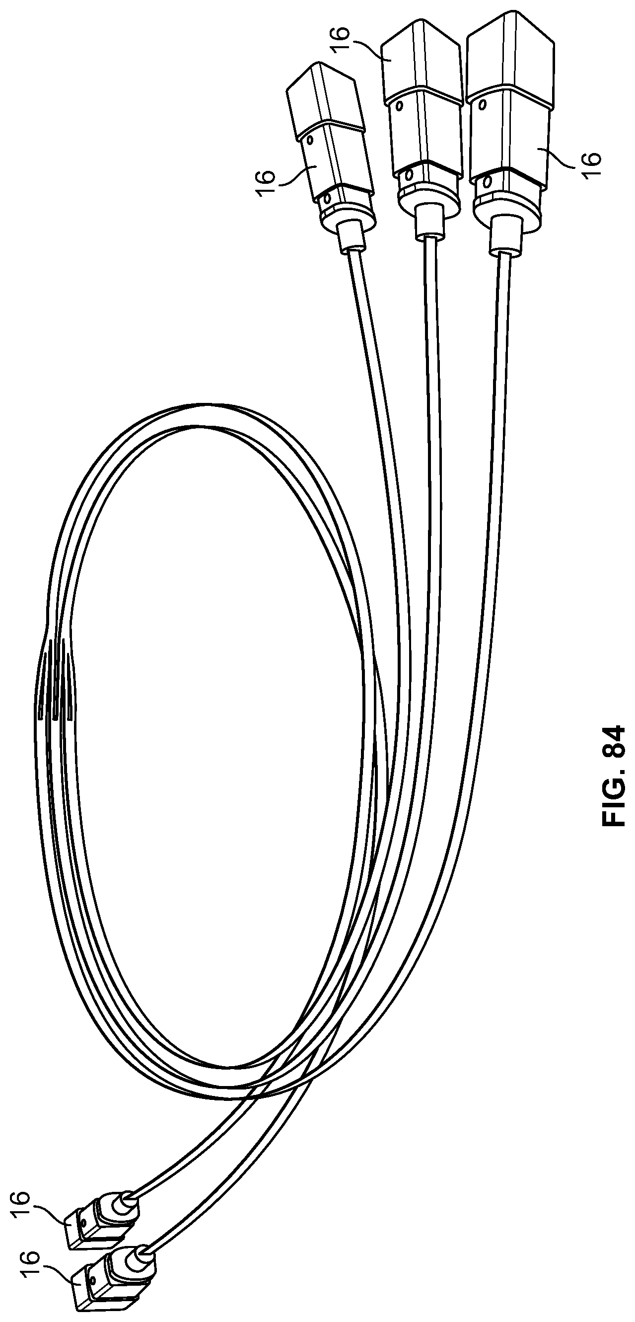
D00076

XML
uspto.report is an independent third-party trademark research tool that is not affiliated, endorsed, or sponsored by the United States Patent and Trademark Office (USPTO) or any other governmental organization. The information provided by uspto.report is based on publicly available data at the time of writing and is intended for informational purposes only.
While we strive to provide accurate and up-to-date information, we do not guarantee the accuracy, completeness, reliability, or suitability of the information displayed on this site. The use of this site is at your own risk. Any reliance you place on such information is therefore strictly at your own risk.
All official trademark data, including owner information, should be verified by visiting the official USPTO website at www.uspto.gov. This site is not intended to replace professional legal advice and should not be used as a substitute for consulting with a legal professional who is knowledgeable about trademark law.