Waveform design for a LiDAR system with closely-spaced pulses
Fine , et al. March 23, 2
U.S. patent number 10,955,552 [Application Number 15/844,665] was granted by the patent office on 2021-03-23 for waveform design for a lidar system with closely-spaced pulses. This patent grant is currently assigned to APPLE INC.. The grantee listed for this patent is APPLE INC.. Invention is credited to Oz Barak, Nadav Fine, Tal Kaitz.


| United States Patent | 10,955,552 |
| Fine , et al. | March 23, 2021 |
Waveform design for a LiDAR system with closely-spaced pulses
Abstract
Depth-sensing apparatus includes a laser, which is configured to emit pulses of optical radiation toward a scene. One or more detectors are configured to receive the optical radiation that is reflected from points in the scene and to output signals indicative of respective times of arrival of the received radiation. Control and processing circuitry is coupled to drive the laser to emit a succession of output sequences of the pulses with different, respective temporal spacings between the pulses within the output sequences in the succession, and to match the times of arrival of input sequences of the signals to the temporal spacings of the output sequences in order to find respective times of flight for the points in the scene.
| Inventors: | Fine; Nadav (Tel Aviv, IL), Barak; Oz (Tel Aviv, IL), Kaitz; Tal (Kiryat Ono, IL) | ||||||||||
|---|---|---|---|---|---|---|---|---|---|---|---|
| Applicant: |
|
||||||||||
| Assignee: | APPLE INC. (Cupertino,
CA) |
||||||||||
| Family ID: | 1000005439565 | ||||||||||
| Appl. No.: | 15/844,665 | ||||||||||
| Filed: | December 18, 2017 |
Prior Publication Data
| Document Identifier | Publication Date | |
|---|---|---|
| US 20190094364 A1 | Mar 28, 2019 | |
Related U.S. Patent Documents
| Application Number | Filing Date | Patent Number | Issue Date | ||
|---|---|---|---|---|---|
| 62563769 | Sep 27, 2017 | ||||
| Current U.S. Class: | 1/1 |
| Current CPC Class: | G01S 17/10 (20130101); G01S 17/894 (20200101); G01S 17/32 (20130101) |
| Current International Class: | G01C 3/08 (20060101); G01S 17/10 (20200101); G01S 17/32 (20200101); G01S 17/894 (20200101) |
References Cited [Referenced By]
U.S. Patent Documents
| 4623237 | November 1986 | Kaneda et al. |
| 4757200 | July 1988 | Shepherd |
| 5164823 | November 1992 | Keeler |
| 5270780 | December 1993 | Moran et al. |
| 5699149 | December 1997 | Kuroda et al. |
| 6301003 | October 2001 | Shirai et al. |
| 6384903 | May 2002 | Fuller |
| 6710859 | March 2004 | Shirai et al. |
| 7126218 | October 2006 | Darveaux et al. |
| 7193690 | March 2007 | Ossig et al. |
| 7303005 | December 2007 | Reis et al. |
| 7405812 | July 2008 | Bamji |
| 7508496 | March 2009 | Mettenleiter et al. |
| 7800067 | September 2010 | Rajavel et al. |
| 7812301 | October 2010 | Dike et al. |
| 7969558 | June 2011 | Hall |
| 8193482 | June 2012 | Itsler |
| 8259293 | September 2012 | Andreou |
| 8275270 | September 2012 | Shushakov et al. |
| 8355117 | January 2013 | Niclass |
| 8405020 | March 2013 | Menge |
| 8675181 | March 2014 | Hall |
| 8736818 | May 2014 | Weimer et al. |
| 8766164 | July 2014 | Sanfilippo et al. |
| 8766808 | July 2014 | Hogasten |
| 8925814 | January 2015 | Schneider et al. |
| 8963069 | February 2015 | Drader et al. |
| 9002511 | April 2015 | Nickerson et al. |
| 9024246 | May 2015 | Jiang et al. |
| 9052356 | June 2015 | Chu et al. |
| 9076707 | July 2015 | Harmon |
| 9016849 | August 2015 | Duggal et al. |
| 9465111 | October 2016 | Wilks et al. |
| 9516248 | December 2016 | Cohen et al. |
| 9709678 | July 2017 | Matsuura |
| 9736459 | August 2017 | Mor et al. |
| 9739881 | August 2017 | Pavek et al. |
| 9786701 | October 2017 | Mellot et al. |
| 9810777 | November 2017 | Williams et al. |
| 9874635 | January 2018 | Eichenholz et al. |
| 10063844 | August 2018 | Adam et al. |
| 10132616 | November 2018 | Wang |
| 10203399 | February 2019 | Retterath |
| 10215857 | February 2019 | Oggier et al. |
| 10269104 | April 2019 | Hannuksela et al. |
| 10386487 | August 2019 | Wilton et al. |
| 10424683 | September 2019 | Do Valle et al. |
| 2001/0020673 | September 2001 | Zappa et al. |
| 2002/0071126 | June 2002 | Shirai et al. |
| 2002/0131035 | September 2002 | Watanabe et al. |
| 2002/0186362 | December 2002 | Shirai et al. |
| 2004/0051859 | March 2004 | Flockencier |
| 2004/0135992 | July 2004 | Munro |
| 2006/0106317 | May 2006 | McConnell et al. |
| 2007/0145136 | June 2007 | Wiklof et al. |
| 2009/0009747 | January 2009 | Wolf et al. |
| 2009/0262760 | October 2009 | Krupkin et al. |
| 2009/0273770 | November 2009 | Bauhahn et al. |
| 2009/0275841 | November 2009 | Melendez et al. |
| 2010/0019128 | January 2010 | Itzler |
| 2010/0045965 | February 2010 | Meneely |
| 2010/0096459 | April 2010 | Gurevich |
| 2010/0121577 | May 2010 | Zhang |
| 2010/0250189 | September 2010 | Brown |
| 2010/0286516 | November 2010 | Fan |
| 2011/0006190 | January 2011 | Alameh et al. |
| 2011/0128524 | June 2011 | Vert et al. |
| 2011/0181864 | July 2011 | Schmitt et al. |
| 2012/0038904 | February 2012 | Fossum et al. |
| 2012/0075615 | March 2012 | Niclass et al. |
| 2012/0132636 | May 2012 | Moore |
| 2012/0153120 | June 2012 | Baxter |
| 2012/0176476 | July 2012 | Schmidt |
| 2012/0249998 | October 2012 | Eisele et al. |
| 2012/0287242 | November 2012 | Gilboa et al. |
| 2012/0294422 | November 2012 | Cheung et al. |
| 2013/0015331 | January 2013 | Birk et al. |
| 2013/0079639 | March 2013 | Hoctor et al. |
| 2013/0092846 | April 2013 | Henning et al. |
| 2013/0208258 | August 2013 | Eisele et al. |
| 2013/0236171 | September 2013 | Saunders |
| 2013/0258099 | October 2013 | Ovsiannikov et al. |
| 2013/0278917 | October 2013 | Korekado et al. |
| 2013/0300838 | November 2013 | Borowski |
| 2013/0342835 | December 2013 | Blacksberg |
| 2014/0027606 | January 2014 | Raynor et al. |
| 2014/0077086 | March 2014 | Batkilin et al. |
| 2014/0078491 | March 2014 | Eisele et al. |
| 2014/0191115 | July 2014 | Webster et al. |
| 2014/0198198 | July 2014 | Geissbuehler et al. |
| 2014/0231630 | August 2014 | Rae et al. |
| 2014/0240317 | August 2014 | Go et al. |
| 2014/0240691 | August 2014 | Mheen et al. |
| 2014/0268127 | September 2014 | Day |
| 2014/0300907 | October 2014 | Kimmel |
| 2014/0321862 | October 2014 | Frohlich et al. |
| 2014/0353471 | December 2014 | Raynor et al. |
| 2015/0041625 | February 2015 | Dutton et al. |
| 2015/0062558 | March 2015 | Koppal et al. |
| 2015/0131080 | May 2015 | Retterath et al. |
| 2015/0163429 | June 2015 | Dai et al. |
| 2015/0192676 | July 2015 | Kotelnikov et al. |
| 2015/0200222 | July 2015 | Webster |
| 2015/0200314 | July 2015 | Webster |
| 2015/0260830 | September 2015 | Ghosh et al. |
| 2015/0285625 | October 2015 | Deane et al. |
| 2015/0362585 | December 2015 | Ghosh et al. |
| 2016/0003944 | January 2016 | Schmidtke et al. |
| 2016/0041266 | February 2016 | Smits |
| 2016/0072258 | March 2016 | Seurin et al. |
| 2016/0080709 | March 2016 | Viswanathan et al. |
| 2016/0259038 | September 2016 | Retterath et al. |
| 2016/0259057 | September 2016 | Ito |
| 2016/0274222 | September 2016 | Yeun |
| 2017/0038459 | February 2017 | Kubacki et al. |
| 2017/0052065 | February 2017 | Sharma et al. |
| 2017/0067734 | March 2017 | Heidemann et al. |
| 2017/0131388 | May 2017 | Campbell et al. |
| 2017/0131718 | May 2017 | Matsumura et al. |
| 2017/0176577 | June 2017 | Halliday |
| 2017/0176579 | June 2017 | Niclass et al. |
| 2017/0179173 | June 2017 | Mandai et al. |
| 2017/0184450 | June 2017 | Doylend et al. |
| 2017/0184704 | June 2017 | Yang et al. |
| 2017/0184709 | June 2017 | Kienzler |
| 2017/0188016 | June 2017 | Hudman et al. |
| 2017/0219695 | August 2017 | Hall et al. |
| 2017/0242102 | August 2017 | Dussan et al. |
| 2017/0242108 | August 2017 | Dussan et al. |
| 2017/0257617 | September 2017 | Retterath |
| 2017/0269209 | September 2017 | Hall |
| 2017/0303789 | October 2017 | Tichauer et al. |
| 2017/0329010 | November 2017 | Warke et al. |
| 2017/0356796 | December 2017 | Nishio |
| 2017/0356981 | December 2017 | Yang et al. |
| 2018/0045816 | February 2018 | Jarosinski et al. |
| 2018/0059220 | March 2018 | Irish et al. |
| 2018/0062345 | March 2018 | Bills et al. |
| 2018/0081032 | March 2018 | Torruellas et al. |
| 2018/0131449 | May 2018 | Kare et al. |
| 2018/0167602 | June 2018 | Pacala et al. |
| 2018/0203247 | July 2018 | Chen et al. |
| 2018/0205943 | July 2018 | Trail |
| 2018/0299554 | October 2018 | Van Dyck et al. |
| 2019/0011567 | January 2019 | Pacala et al. |
| 2019/0018118 | January 2019 | Perenzoni et al. |
| 2019/0018143 | January 2019 | Thayer et al. |
| 2019/0056497 | February 2019 | Pacala et al. |
| 2019/0170855 | June 2019 | Keller et al. |
| 2020/0314294 | October 2020 | Schoenlieb et al. |
| 103763485 | Apr 2014 | CN | |||
| 104914446 | Sep 2015 | CN | |||
| 106405572 | Feb 2017 | CN | |||
| 202013101039 | Mar 2014 | DE | |||
| 2157445 | Feb 2010 | EP | |||
| 2469297 | Jun 2012 | EP | |||
| 2477043 | Jul 2012 | EP | |||
| 2827175 | Jan 2015 | EP | |||
| 3285087 | Feb 2018 | EP | |||
| 3318895 | May 2018 | EP | |||
| H02287113 | Nov 1990 | JP | |||
| H0567195 | Mar 1993 | JP | |||
| 09197045 | Jul 1997 | JP | |||
| H10170637 | Jun 1998 | JP | |||
| H11063920 | Mar 1999 | JP | |||
| 2011089874 | May 2011 | JP | |||
| 2013113669 | Jun 2013 | JP | |||
| 2014059301 | Apr 2014 | JP | |||
| 2010149593 | Dec 2010 | WO | |||
| 2015199615 | Dec 2015 | WO | |||
| 2020101576 | May 2020 | WO | |||
| 2020201452 | Oct 2020 | WO | |||
Other References
|
US. Appl. No. 15/586,286 office action dated Dec. 2, 2019. cited by applicant . International Application # PCT/US2019/45187 search report dated Nov. 15, 2019. cited by applicant . U.S. Appl. No. 14/830,760 office action dated Mar. 27, 2019. cited by applicant . Japanese Application # 2018-530709 office action dated Jun. 10, 2019. cited by applicant . CN Application # 2018-20865151.7 Utility Model Patentability Evaluation Report dated Jul. 3, 2019. cited by applicant . U.S. Appl. No. 15/586,300 office action dated Jul. 11, 2019. cited by applicant . U.S. Appl. No. 15/586,300 office action dated Sep. 20, 2019. cited by applicant . Lin et al., "Chaotic lidar", IEEE Journal of Selected Topics in Quantum Electronics, vol. 10, issue 5, pp. 391-997, Sep.-Oct. 2004. cited by applicant . Chung et al., "Optical orthogonal codes: design, analysis and applications", IEEE Transactions on Information Theory, vol. 35, issue 3, pp. 595-604, May 1989. cited by applicant . Ai et al., "High-resolution random-modulation cw lidar", Applied Optics, vol. 50, issue 22, pp. 4478-4488, Jul. 28, 2011. cited by applicant . Morbi et al., "Short range spectral lidar using mid-infrared semiconductor laser with code-division multiplexing technique", Technical Digest, CLEO 2001, pp. 491-492 pages, May 2001. cited by applicant . Charbon et al., "SPAD-Based Sensors", TOF Range-Imaging Cameras, Springer-Verlag, pp. 11-38, year 2013. cited by applicant . Niclass et al., "A 0.18 um CMOS SoC fora 100m range, 10 fps 200.times.96 pixel Time of Flight depth sensor", IEEE International Solid-State Circuits Conference--(ISSCC), Session 27, Image Sensors, 27.6, pp. 488-490, Feb. 20, 2013. cited by applicant . Walker et al., "A 128.times.96 pixel event-driven phase-domain .DELTA..SIGMA.-based fully digital 3D camera in 0.13.mu.m CMOS imaging technology", IEEE International Solid-State Circuits Conference--(ISSCC), Session 23, Image Sensors, 23.6, pp. 410-412, Feb. 23, 2011. cited by applicant . Niclass et al., "Design and characterization of a 256.times.64-pixel single-photon imager in CMOS for a MEMS-based laser scanning time-of-flight sensor", Optics Express, vol. 20, issue 11, pp. 11863-11881, May 21, 2012. cited by applicant . Kota et al., "System Design and Performance Characterization of a MEMS-Based Laser Scanning Time-of-Flight Sensor Based on a 256.times.64-pixel Single-Photon Imager", IEEE Photonics Journal, vol. 5, issue 2, 15 pages, Apr. 2013. cited by applicant . Webster et al., "A silicon photomultiplier with >30% detection efficiency from 450-750nm and 11.6.mu.m pitch NMOS-only pixel with 21.6% fill factor in 130nm CMOS", Proceedings of the European Solid-State Device Research Conference (ESSDERC) , pp. 238-241, Sep. 7-21, 2012. cited by applicant . Niclass et al., U.S. Appl. No. 15/586,286, filed May 4, 2017. cited by applicant . Niclass et al., U.S. Appl. No. 15/586,300, filed May 4, 2017. cited by applicant . U.S. Appl. No. 14/830,760 office action dated Feb. 22, 2018. cited by applicant . Buttgen et al., "Pseudonoise Optical Modulation for Real-Time 3-D Imaging With Minimum Interference", IEEE Transactions on Circuits and Systems I: Regular Papers, vol. 54, Issue10, pp. 2109-2119, Oct. 1, 2007. cited by applicant . Bradski et al., "Learning OpenCV", first edition, pp. 1-50, O'Reilly Media, Inc, California, USA, year 2008. cited by applicant . CN Utility Model Patent No. 201520865151.7 UMPER report dated Oct. 9, 2019. cited by applicant . International Application PCT/US2019/45188 Search Report dated Oct. 21, 2019. cited by applicant . International Application # PCT/US2018/026993 search report dated Aug. 9, 2018. cited by applicant . U.S. Appl. No. 15/372,411 office action dated Sep. 5, 2018. cited by applicant . U.S. Appl. No. 14/830,760 office action dated Sep. 27, 2018. cited by applicant . U.S. Appl. No. 15/372,411 office action dated May 9, 2018. cited by applicant . U.S. Appl. No. 15/586,286 office action dated Feb. 24, 2020. cited by applicant . EP Application No. 20177707 Search Report dated Sep. 29, 2020. cited by applicant . U.S. Appl. No. 15/950,186 office action dated Jun. 23, 2020. cited by applicant . U.S. Appl. No. 16/532,517 Office Action dated Oct. 14, 2020. cited by applicant . EP Application # 20177707.5 Search Report dated Nov. 12, 2020. cited by applicant . JP Application # 2020001203 Office Action dated Feb. 4, 2021. cited by applicant . U.S. Appl. No. 16/752,653 Office Action dated Feb. 4, 2021. cited by applicant. |
Primary Examiner: Abraham; Samantha K
Attorney, Agent or Firm: Kligler & Associates Patent Attorneys Ltd
Parent Case Text
CROSS-REFERENCE TO RELATED APPLICATION
This application claims the benefit of U.S. provisional patent application 62/563,769, filed Sep. 27, 2017.
Claims
The invention claimed is:
1. Depth-sensing apparatus, comprising: a laser, which is configured to emit pulses of optical radiation toward a scene; one or more detectors, which are configured to receive the optical radiation that is reflected from points in the scene and to output signals indicative of respective times of arrival of the received radiation; and control and processing circuitry, which is coupled to drive the laser to emit a succession of output sequences of the pulses such that successive output sequences within the succession have different, respective temporal spacings between the pulses within each of the successive output sequences, and to match the times of arrival of input sequences of the signals to the temporal spacings of the output sequences in order to find respective times of flight for the points in the scene.
2. The depth-sensing apparatus according to claim 1, wherein the output sequences comprise temporally-separated tuples of the pulses.
3. The depth-sensing apparatus according to claim 1, wherein the output sequences are mutually overlapping.
4. The depth-sensing apparatus according to claim 3, wherein each output sequence comprises a number N of pulses, such that N>1, and wherein consecutive output sequences have N-1 pulses in common, such that a second pulse of any given output sequence is a first pulse of a succeeding output sequence.
5. The depth-sensing apparatus according to claim 1, wherein the control and processing circuitry is configured to identify a signal output by the one or more detectors due to a stray-light pulse, to identify an emitted pulse in an input sequence that temporally coincides with the stray-light pulse, and to remove the identified pulse from the input sequence while adding to the input sequence a further pulse from a neighboring sequence in matching the times of arrival.
6. The depth-sensing apparatus according to claim 1, wherein the control and processing circuitry is configured to construct a depth map of the scene based on the times of flight.
7. The depth-sensing apparatus according to claim 1, wherein the control and processing circuitry is configured to match the times of arrival of the pulses in each input sequence to the temporal spacings of the output sequences by calculating a respective fit between the times of arrival of the input sequence and each output sequence within a selected time period, calculating a residual of each respective fit, and identifying the output sequence yielding a minimum value of the residual among all residuals as the output sequence associated with the input sequence.
8. The depth-sensing apparatus according to claim 7, wherein the control and processing circuitry is configured, in calculating the respective fit, to apply a linear transformation to each output sequence to account for a tilt of a planar region of the scene relative to a line of sight of the apparatus, and to calculate the respective fit between the times of arrival of each input sequence and each output sequence following the linear transformation.
9. A method for depth sensing, comprising: emitting a succession of output sequences of pulses of optical radiation toward a scene, such that successive output sequences within the succession have different, respective temporal spacings between the pulses within each of the successive output sequences; receiving the optical radiation that is reflected from points in the scene at one or more detectors, which output signals indicative of respective times of arrival of the received radiation; and matching the times of arrival of input sequences of the signals to the temporal spacings of the output sequences in order to find respective times of flight for the points in the scene.
10. The method according to claim 9, wherein the output sequences comprise temporally-separated tuples of the pulses.
11. The method according to claim 9, wherein the output sequences are mutually overlapping.
12. The method according to claim 11, wherein each output sequence comprises a number N of pulses, such that N>1, and wherein consecutive output sequences have N-1 pulses in common, such that a second pulse of any given output sequence is a first pulse of a succeeding output sequence.
13. The method according to claim 9, wherein matching the times of arrival comprises identifying a signal output by the one or more detectors due to a stray-light pulse, identifying an emitted pulse in an input sequence that temporally coincides with the stray-light pulse, and removing the identified pulse from the input sequence while adding to the input sequence a further pulse from a neighboring sequence in matching the times of arrival.
14. The method according to claim 9, and comprising constructing a depth map of the scene based on the times of flight.
15. The method according to claim 9, wherein matching the times of arrival comprises calculating a respective fit between the times of arrival of the input sequence and each output sequence within a selected time period, calculating a residual of each respective fit, and identifying the output sequence yielding a minimum value of the residual among all residuals as the output sequence associated with the input sequence.
16. The method according to claim 15, wherein calculating the respective fit comprises applying a linear transformation to each output sequence to account for a tilt of a planar region of the scene relative to a line of sight of the apparatus, and calculating the respective fit between the times of arrival of each input sequence and each output sequence following the linear transformation.
Description
FIELD OF THE INVENTION
The present invention relates generally to range sensing, and particularly to devices and methods for depth mapping based on time-of-flight measurement.
BACKGROUND
Time-of-flight (ToF) imaging techniques are used in many depth mapping systems (also referred to as 3D mapping or 3D imaging). In direct ToF techniques, a light source, such as a pulsed laser, directs pulses of optical radiation toward the scene that is to be mapped, and a high-speed detector senses the time of arrival of the radiation reflected from the scene. The depth value at each pixel in the depth map is derived from the difference between the emission time of the outgoing pulse and the arrival time of the reflected radiation from the corresponding point in the scene, which is referred to as the "time of flight" of the optical pulses. The radiation pulses that are reflected back and received by the detector are also referred to as "echoes."
In order to determine the ToF of each pulse unambiguously, the time interval between consecutive pulses is chosen to be longer than the ToF. This guarantees that only one pulse is "in the air" at a given time, and that the control and processing circuitry receiving the detected signals and determining the ToF knows when each received pulse was emitted by the light source.
SUMMARY
Embodiments of the present invention that are described hereinbelow provide improved LiDAR systems and methods for ToF-based ranging and depth mapping.
There is therefore provided, in accordance with an embodiment of the invention, depth-sensing apparatus, including a laser, which is configured to emit pulses of optical radiation toward a scene. One or more detectors are configured to receive the optical radiation that is reflected from points in the scene and to output signals indicative of respective times of arrival of the received radiation. Control and processing circuitry is coupled to drive the laser to emit a succession of output sequences of the pulses with different, respective temporal spacings between the pulses within the output sequences in the succession, and to match the times of arrival of input sequences of the signals to the temporal spacings of the output sequences in order to find respective times of flight for the points in the scene.
In some embodiments, the output sequences include temporally-separated tuples of the pulses.
Alternatively, the output sequences are mutually overlapping. In one such embodiment, each output sequence includes N pulses, and consecutive output sequences have N-1 pulses in common, such that a second pulse of any given output sequence is a first pulse of a succeeding output sequence.
In some embodiments, the control and processing circuitry is configured to identify a signal output by the one or more detectors due to a stray-light pulse, to identify an emitted pulse in an input sequence that temporally coincides with the stray-light pulse, and to remove the identified pulse from the input sequence while adding to the input sequence a further pulse from a neighboring sequence in matching the times of arrival.
In a disclosed embodiment, a maximal length of the output sequences is minimized responsively to a minimal size of objects in the scene that are to be detected.
Additionally or alternatively, the control and processing circuitry is configured to construct a depth map of the scene based on the times of flight.
In some embodiments, the control and processing circuitry is configured to match the times of arrival of the pulses in each input sequence to the temporal spacings of the output sequences by calculating a respective fit between the times of arrival of the input sequence and each output sequence within a selected time period, calculating a residual of each respective fit, and identifying the output sequence yielding a minimum among all residuals as the output sequence associated with the input sequence. In a disclosed embodiment, the control and processing circuitry is configured, in calculating the respective fit, to apply a linear transformation to each output sequence to account for a tilt of the scene, and to calculate the respective fit between the times of arrival of each input sequence and each output sequence following the linear transformation. Additionally or alternatively, the output sequences are defined so as to maximize the residuals of the output sequences other than the identified output sequence
There is also provided, in accordance with an embodiment of the invention, a method for depth sensing, which includes emitting a succession of output sequences of pulses of optical radiation toward a scene, with different, respective temporal spacings between the pulses within the output sequences in the succession. The optical radiation that is reflected from points in the scene is received at one or more detectors, which output signals indicative of respective times of arrival of the received radiation. The times of arrival of input sequences of the signals are matched to the temporal spacings of the output sequences in order to find respective times of flight for the points in the scene.
The present invention will be more fully understood from the following detailed description of the embodiments thereof, taken together with the drawings in which:
BRIEF DESCRIPTION OF THE DRAWINGS
FIG. 1 is a schematic side view of a depth-sensing apparatus, in accordance with an embodiment of the invention;
FIG. 2 is a schematic plot of emitted pulses in tuple structures, in accordance with an embodiment of the invention;
FIG. 3 is a schematic plot of emitted pulses in dither structures, in accordance with another embodiment of the invention; and
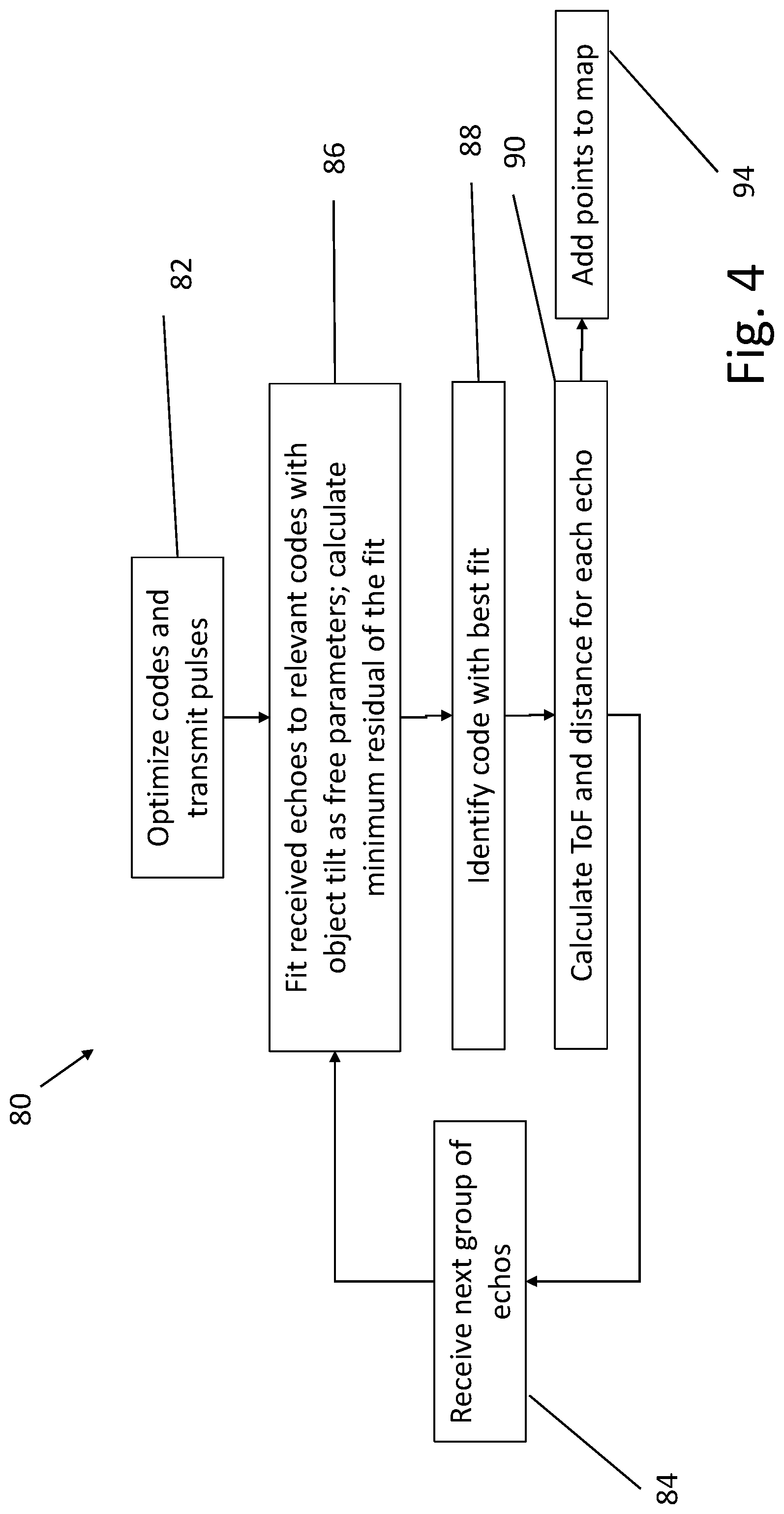
FIG. 4 is a flowchart that schematically illustrates a method for optimizing and applying codes of tuple and dither structures, in accordance with an embodiment of the invention.
DETAILED DESCRIPTION OF EMBODIMENTS
The quality of measurement of the distance to each point in a scene using a LiDAR is often compromised in practical implementations by a number of environmental, fundamental, and manufacturing challenges. An example of environmental challenges is the presence of uncorrelated background light, such as solar ambient light, in both indoor and outdoor applications, typically reaching an irradiance of 1000 W/m.sup.2. Some of the fundamental challenges are related to losses incurred by optical signals upon reflection from the surfaces in the scene, especially due to low-reflectivity surfaces and limited optical collection aperture, as well as electronic and photon shot noises. Other fundamental challenges are related to the conflict between the requirements for high scanning and sampling speeds and the limits imposed by a finite ToF.
These limitations often generate inflexible trade-off relationships that can push the designer to resort to solutions involving large optical apertures, high optical power, narrow field-of-view (FoV), bulky mechanical construction, low frame rate, and the restriction of sensors to operation in controlled environments.
ToF-based LiDARs that are known in the art operate typically either in a single-shot mode or in a multi-shot mode. In the single-shot mode, a single laser pulse is transmitted toward the scene for each pixel that is to appear in the depth image. In multi-shot mode, LiDAR systems that are known in the art transmit identical sequences of several pulses toward the scene. Each of these two modes has its advantages and disadvantages relating to various performance characteristics, such as throughput and frame rate, peak power, rejection of ambient light, and robustness with respect to interference.
Both modes, however, are limited in their throughput by the fundamental limitation imposed by ToF: In order to avoid confusion between the echoes of successive transmitted pulses (or pulse sequences), the time interval between successive pulses (or pulse sequences) is set to be no less than the expected maximum ToF value. In long-range LiDAR systems, the expected maximum ToF will be correspondingly large (for example, on the order of 1 .mu.s for a range of 100 m). This example would set an upper limit on the order of 1 MHz to the frequency at which the scene is sampled, which in turn limits the LiDAR throughput and hence limits either the spatial resolution of the depth map or the FoV of the LiDAR. The maximum ToF may be dictated by maximum range of objects in the scene that are to be detected, or alternatively by the maximum range from which an echo can be received in the LiDAR, either due to drop-off of echo intensity with distance or due to turning of the acceptance angle of the optical imaging system.
Embodiments of the present invention that are described herein provide a LiDAR that is capable of avoiding the confusion between pulses or pulse sequences that are emitted at time intervals shorter than the expected values of ToF. This, in turn, enables the LiDAR to operate at a higher throughput and to map the scene either at a higher spatial resolution or with a larger FoV than otherwise possible.
In the disclosed embodiments, depth-sensing apparatus comprises a laser, which emits pulses of optical radiation toward a scene, and one or more detectors, which receive the optical radiation that is reflected from points in the scene and output signals indicative of respective times of arrival of these echo pulses. Control and processing circuitry drives the laser to emit a succession of output sequences of pulses with different, respective temporal spacings between the pulses within the output sequences. The times of arrival of input sequences of the signals are matched to the temporal spacings of the output sequences in order to find respective times of flight for the points in the scene. These times of flight are used, for example, in constructing a depth map of the scene.
In a disclosed embodiment, the light source emits the pulses in each output sequence at predetermined but uneven intervals. A series of numbers denoting the uneven intervals within a sequence are referred to as the "coding" of the given sequence. The codings of successive output sequences are designed to differ from one another according to a metric, which will be described in detail in the context of the figures. When this approach is used, the received echoes may be uniquely matched to a given output sequence, and the time interval between two consecutive output sequences may be substantially shorter than the expected ToF, with the above-mentioned advantages due to increased throughput and sampling rate.
Echoes of the emitted pulses are received by the detectors, which output corresponding signals to the control and processing circuitry of the LiDAR. Each sequence of the echoes can be assumed to have been reflected by a linear (planar) region of the scene, which is a reasonable assumption for a densely-sampled scene. The tilt of the planar region with respect to the line-of-sight from the LiDAR to the scene will manifest itself as a linear stretch of an output sequence by the time it reaches the detectors as echoes, and the distance to the scene causes a temporal shift in the output sequence due to ToF.
The control and processing circuitry performs a fit of a received sequence of echoes to the output sequences, with a linear stretch of the sequence as an adjustable parameter, and calculates the residual of each fit. Each residual is further minimized by adjusting for the assumed scene tilt (sequence stretch). The output sequence for which the residual of the fit reaches a minimum value is identified by the control and processing circuitry with the received sequence. As the emission times of each of the pulses in the identified output sequence are known, the ToF can now be calculated for each of the echoes as the difference between the time of arrival of the echo and the time of emission of the corresponding emitted pulse.
The disclosed embodiments make use of two different pulse structures, which will be further detailed in the context of FIGS. 2-3: The first structure, referred to as a "tuple" structure, comprises discrete, i.e. temporally separated, sequences of pulses. In a tuple structure, the typical number of pulses is three, and the tuple duration is typically an order of magnitude lower than the interval between tuples.
The second structure, referred to as a "dither" structure, comprises a continuous series of pulses, wherein the temporal location of each pulse is modulated (i.e., shifted) around a fiducial, with a typical dither between 50% and 200% of the average interval between pulses. For a general dither structure, every N consecutive pulses form a dither structure with an associated code, and a new structure (and a new associated code) starts after a shift of one pulse. Consequently, consecutive dither structures of N pulses overlap by N-1 pulses.
Although in the disclosed embodiments, three pulses are used for both tuple and dither structures, other numbers of pulses may alternatively be used, as will be detailed below.
A small portion of each pulse emitted by the light source may be reflected by an optical or mechanical surface of the LiDAR directly back to the detectors. These stray-light pulses received by a detector may briefly blind it, and in this way occlude one or more of the echoes received from the scene. The dither sequence can be selected so as to prevent consistent blinding of echoes from a scene located at any expected distance from the LiDAR. For this purpose, the control and processing circuitry checks, in a general case, N received echoes and compares the times of arrival of the echoes to known times of arrival for stray-light pulses. In case one of the echoes coincides with a stray-light pulse, this echo is ignored, and an echo adjacent to the original N echoes is added to the sequence for purposes of fitting to relevant output sequences. In other words, in processing the stream of echoes, it is assumed that at most one echo coincides with a stray-light pulse in a code of length N. If a match to a code is found under these conditions (N-1 matches with proper echoes, one match to a stray time), the detection is confirmed using another proper echo. This assumption can be made valid for any possible target ToF if the coding series of pulses is designed as defined hereinbelow.
If a scene contains a small object, i.e., an object that presents a small lateral dimension to the LiDAR, the object may not be detected unless a given minimum number of echoes is received from it. The sequence code can be optimized for detecting small objects by minimizing the maximum code length of the output sequences.
The resolution of the mapping corresponds to the sampling rate of the scene. For tuple structures this is typically the interval between neighboring tuple structures, and thus independent of the specific code of the tuple structure. For dither structures the resolution may be increased by reducing the pulse-to-pulse spacing, i.e., modifying the code.
FIG. 1 is a schematic side view of a depth-sensing apparatus 20, in accordance with an embodiment of the invention. In the pictured embodiment, device 20 is used to generate depth maps of a scene including an object 22, for example a part of the body of a user of the device. To generate the depth map, an illumination assembly 24 directs pulses of light toward object 22, and an imaging assembly measures the ToF of the photons reflected from the object. (The term "light," as used in the present description and in the claims, refers to optical radiation, which may be in any of the visible, infrared, and ultraviolet ranges.)
Illumination assembly 24 typically comprises a pulsed laser 28, which emits short pulses of light, with pulse duration in the nanosecond range and repetition frequency in the range of 0.5-50 MHz, for example. Projection optics 30 direct the light toward object 22. Alternatively, other pulse durations and repetition frequencies may be used, depending on application requirements. In some embodiments, illumination assembly 24 comprises a scanner, such as one or more rotating mirrors (not shown), which scans the beam of pulsed light across the scene. In other embodiments, illumination assembly comprises an array of lasers, in place of laser 28, which illuminates different parts of the scene either concurrently or sequentially. More generally, illumination assembly 24 may comprise substantially any pulsed laser or laser array that can be driven to emit sequences of pulses toward object 22 at irregular intervals.
Imaging assembly 26 comprises objective optics 32, which image object 22 onto one or more detectors, represented in the figure by a sensing array 34, so that photons emitted by illumination assembly 24 and reflected from object 22 are incident on the sensing device. In the pictured embodiment, sensing array 34 comprises a sensor chip 36 and a processing chip 38, which are coupled together, for example, using chip stacking techniques that are known in the art. Sensor chip 36 comprises one or more high-speed photodetectors, such as avalanche photodiodes.
In some embodiments, sensor chip 36 comprises a single photodetector, such as a single avalanche photodiode or SPAD. In other embodiments, the photodetectors in sensor chip 36 comprise an array of SPADs 40, each of which outputs a signal indicative of the times of incidence of photons on the SPAD following emission of pulses by illumination assembly 24. Processing chip 38 comprises an array of processing circuits 42, which are coupled respectively to the sensing elements. Both of chips 36 and 38 may be produced from silicon wafers using well-known CMOS fabrication processes, based on SPAD sensor designs that are known in the art, along with accompanying drive circuits, logic and memory. For example, chips 36 and 38 may comprise circuits as described in U.S. Patent Application Publication 2017/0052065 and/or U.S. Patent Application Publication 2017/0179173, both of whose disclosures are incorporated herein by reference. Alternatively, the designs and principles of detection that are described herein may be implemented, mutatis mutandis, using other circuits, materials and processes. All such alternative implementations are considered to be within the scope of the present invention.
Imaging assembly 26 outputs signals that are indicative of respective times of arrival of the received radiation at each SPAD 40 or, equivalently, from each point in the scene that is being mapped. These output signals are typically in the form of respective digital values of the times of arrival that are generated by processing circuits 42, although other signal formats, both digital and analog, are also possible. A controller 44 reads out the individual pixel values and generates an output depth map, comprising the measured ToF--or equivalently, the measured depth value--at each pixel. The depth map is typically conveyed to a receiving device 46, such as a display or a computer or other processor, which segments and extracts high-level information from the depth map.
As explained above, controller 44 drives the laser or lasers in illumination assembly 24 to emit sequences of pulses in a predefined temporal pattern, with irregular intervals between the pulses in the sequence. Processing chip 38 or controller 44 then finds the respective times of flight for the points in the scene by matching the times of arrival of input sequences of the signals to the temporal spacings of the output sequences, which are shared with controller 44. The process of matching will be further detailed in the context of FIGS. 2-3, below.
Although the present description relates to controller and processing chip 38 as separate entities, with a certain division of functions between the controller and processing chip, in practice these entities and their functions may be combined and implemented monolithically on the same integrated circuit. Alternatively, other divisions of functionality between these entities will also be apparent to those skilled in the art and are considered to be within the scope of the present invention. Therefore, in the present description and in the claims, controller 44 and processing chip 38 are referred to collectively as "control and processing circuitry," and this term is meant to encompass all implementations of the functionalities that are attributed to these entities.
FIG. 2 is a schematic plot of emitted pulses 52 arranged in tuple structures 54 and 55, in accordance with an embodiment of the invention. Pulses 52 are emitted by pulsed laser 28. In the present embodiment each tuple structure comprises three pulses 52, shown as upright arrows on a time axis 56. Two tuple structures 54 and 55 are shown in FIG. 2, with tuple structure 54 labelled as B.sup.i for the i.sup.th tuple structure and tuple structure 55 labelled as B.sup.i+1 for the i+1.sup.st tuple structure. Index i represents a series of positive integers.
Fiducials z.sub.j.sup.i on time axis 56 are shown as dotted lines 58, wherein i is the index of tuple structure B.sup.i and j is the index of the pulses within the structure. For a tuple structure comprising three pulses, j=0,1,2. Fiducials Z.sub.j.sup.i are equidistant from each other within each tuple structure B.sup.i and are used for defining temporal shifts a.sub.j.sup.i, wherein, as for the fiducials, the index i refers to the i.sup.th structure B.sup.i and j is the index within the structure. Each a.sub.j.sup.i is defined as a signed difference between fiducial z.sub.j.sup.i and a temporal position t.sub.j.sup.i of the j.sup.th pulse within the i.sup.th structure B.sup.i: a.sub.j.sup.i=t.sub.j.sup.i-z.sub.j.sup.i. Alternatively, the pulse intervals can be defined as the difference between the pulse positions and the code center, which is the average of the pulse times. The temporal distance A.sup.i, i+1 between structures B.sup.i and B.sup.i+1 is defined as the temporal difference between the first fiducial of each tuple: A.sup.i,i+1=z.sub.0.sup.i+1-z.sub.0.sup.i. The temporal distance between tuples A.sup.i,i+1 may be either uniform or different between consecutive tuples.
FIG. 3 is a schematic plot of emitted pulses 62 arranged in dither structures 68 and 70, in accordance with another embodiment of the invention. Pulses 62 are emitted by pulsed laser 28. In the present embodiment, emitted pulses 62, shown as upright arrows on a time axis 64, are labelled by index j, wherein the index represents a series of consecutive positive integers. The temporal position of the j.sup.th pulse is labelled by t'.sub.j, and is shifted with respect to a fiducial z'.sub.j, wherein all consecutive fiducials are equidistant from each other with a temporal spacing of D. D is the average temporal distance between consecutive pulses 62. The fiducials z'.sub.1 are marked by dotted lines 66. Alternatively, the code can be defined in terms of the differences of the temporal positions of the pulses from the code center (which varies as a result of the interval modulation).
A dither structure 68, labelled as C.sup.i, with i referring to the i.sup.th dither structure, comprises three emitted pulses j, j+1, and j+2. Index i represents a series of positive integers. A subsequent dither structure 70, labelled as C.sup.i+1, comprises three pulses j+1, j+2, and j+3. Thus, consecutive dither structures C.sup.i and C.sup.i+1 overlap for pulses j+1 and j+2. This overlap differentiates dither structures C.sup.i and C.sup.i+1 from tuple structures B.sup.i and B.sup.i+1 of FIG. 2, as there is no overlap between consecutive tuple structures. However, as the same mathematical operations will be performed below for both optimization and fitting for both tuple structures and dither structures, the same notation a.sub.j.sup.i will be used for temporal shifts of pulses 62 in dither structures as was used for tuple structures in FIG. 2, with a definition that takes into account the differences in indexing between the two structures.
For the i.sup.th dither structure C.sup.i, the temporal shift a.sub.j.sup.i is defined as the signed difference between fiducial z'.sub.j and temporal position t'.sub.j of the j.sup.th pulse: a.sub.j.sup.i=t'.sub.j-z'.sub.j, wherein the index i is determined by the association of the temporal shift with the i.sup.th dither structure C.sup.i. This notation is further clarified by observing the notation for the temporal shifts for dither structures C.sup.i and C.sup.i+1 (dither structures C.sup.i-1 and C.sup.i+2 are ignored for the sake of simplicity): Pulse 0 in dither structure C.sup.i is shifted by a.sub.0.sup.i. Pulse 1 in dither structure C.sup.i is shifted by a.sub.1.sup.i, but as this pulse is also pulse 0 in dither structure C.sup.i+1, a.sub.1.sup.i=a.sub.0.sup.i+1. Similar equality is found between pulse 2 of dither structure C.sup.i and pulse 1 of dither structure C.sup.i+1. Pulse 2 of dither structure C.sup.i+1 is already outside dither structure C.sup.i.
Both tuple structures and dither structures can be used for mapping object 22 with two degrees of freedom: the distance from depth-sensing apparatus 20 to the object and the inclination of the object in the direction of relative movement between the depth-sensing apparatus and the object. (The relative movement may be caused by a scanner which scans the beam of pulsed light across the object, or due to a movement of the object, or both.) In order to map these two degrees of freedom, a minimum number of three received pulses is required, wherein the third degree of freedom is used to resolve code association ambiguity, as explained below. The disclosed embodiments therefore use three-pulse tuple structures, as well as three-pulse dither structures. The three temporal shifts (a.sub.0.sup.i, a.sub.1.sup.i, a.sub.2.sup.i) for structure i (either a tuple or a dither structure) define the code for that structure.
In other embodiments of the present invention, tuple or dither structures with more than three pulses (for example four, five, or six pulses) may be used for mapping with two or more degrees of freedom. Alternatively, in some cases tuples or dither structures of only two pulses may be used.
FIG. 4 is a flowchart 80 that schematically illustrates a method for optimizing and applying codes of tuple and dither structures, in accordance with an embodiment of the invention. This method can be applied, for example by controller 44, in setting the pulse timing of laser 28 in operation, as well as in processing the signals output by sensor chip 36. Alternatively, the codes can be pre-computed.
In an optimization step 82, M codes (a.sub.0.sup.i, a.sub.1.sup.i, a.sub.2.sup.i) are optimized, wherein index i=1, . . . , M, and M may take any suitable value, depending on application requirements. The objective of the optimization is to ensure that the codes are sufficiently different to enable a unique identification of the code with a best fit to the received echoes. The optimization is performed by a maximization of the minimum value with i.+-.k of the following expression:
.function. ##EQU00001## wherein X.sup.P denotes an orthogonal projection on the columns of matrix X, and
.times..times..times..times..times..times. ##EQU00002## Laser 28 transmits sequences of pulses toward a scene, with the intervals between the pulses determined by the optimized codes.
In a receiving step 84, sensor chip 36 receives three echoes (three pulses reflected by object 22). In a fitting step 86, controller 44 fits the received echoes to relevant codes. The relevant codes are chosen among codes whose known transmission times are within the expected transmission times of the received echoes, considering the operating range of depth-sensing apparatus 20. Controller 44 can expand (stretch) a relevant code i (a.sub.0.sup.i, a.sub.1.sup.i, a.sub.2.sup.i) linearly to a hypothesized code (a.sub.0.sup.i, a.sub.1.sup.i, a.sub.2.sup.i), wherein the tilt of object 22, i.e., a linear expansion of the code, is used as a free parameter. The controller calculates the residual of the fit as:
.function. ##EQU00003## wherein t.sub.0, t.sub.1, and t.sub.2 are the times at which the echoes are received. The residual for each code is minimized by adjusting the object tilt for that code. The third degree of freedom will cause the residue to be large in case of a mismatch between the code and echo time set, thus resolving any possible ambiguity.
In an identification and calculation step 88, controller 44 identifies the code with the best fit (smallest residual) as the output structure that emitted the pulses that were received as the echoes at times t.sub.0, t.sub.1, and t.sub.2. When the emitted pulses are arranged in tuple structures, as shown in FIG. 2, and assuming, for example, that the identified code is that of tuple structure B.sup.i, the echo received at time to corresponds to the pulse emitted at time t.sub.0.sup.i, the echo received at time t.sub.1 corresponds to the pulse emitted at time t.sub.1.sup.i, and the echo received at time t.sub.2 corresponds to the pulse emitted at time t.sub.2.sup.i.
Alternatively, when the emitted pulses are arranged in dither structures, as shown in FIG. 3, and assuming, for example, that the identified code is that of dither structure C.sup.i, the echo received at time t.sub.0 corresponds to the pulse emitted at time t'.sub.j, the echo received at time t.sub.1 corresponds to the pulse emitted at time t'.sub.j+1, and the echo received at time t.sub.2 corresponds to the pulse emitted at time t'.sub.j+2.
In a calculation step 90, controller 44 computes the ToF for each of the received echoes as the difference between the time the echo was received and the time--based on identification step 88--when the corresponding pulse was emitted. The distance to each point on object 22 from which an echo was returned is calculated from the ToF as c.times.ToF/2, wherein c is the speed of light. Controller 44 transfers the calculated distances to a map of object 22 in a mapping step 94. If more echoes are to be received, the process returns to receiving step 84.
As noted earlier, the dither structure can be designed to prevent blinding of echoes. A small portion of each pulse emitted by the pulsed laser 28 may be reflected by an optical or mechanical surface of the LiDAR directly back to sensor chip 36. In case such a stray-light pulse coincides with an echo received from object 22, the echo may not be detected due to the blinding of sensor chip 36 by the stray-light pulse. To alleviate this problem, controller 44 compares the arrival times of N echoes to known times of arrival of stray-light pulses. In case one of the N echoes coincides with a stray-light pulse, this echo is ignored, an echo adjacent to the N echoes is added to the sequence, and the fit of the modified echo sequence to relevant output sequences is calculated.
Typically, three echoes are used for a code (N=3), requiring that out of four consecutive echoes, three are far from stray-light returns. The criterion for dither structures is formulated as follows: Denote by d.sub.j the time intervals between pulses in the coded sequence, and L the number of intervals in the coded sequence. The set of sums of intervals of length k is: A.sub.k={0.ltoreq.i.ltoreq.L-1|d.sub.i+ . . . +d.sub.mod(i+k-1,L)}, wherein the elements d.sub.j represent the intervals between pulses in the codes. The elements of A.sub.k are denoted by b.sub.k.sup.l. When using three out of four echoes, as explained above, the expression to be maximized is |b.sub.k.sub.0.sup.l.sup.0-b.sub.k.sub.1.sup.l.sup.1| for (k.sub.0l.sub.0).+-.(k.sub.1l.sub.1) and k.sub.0.ltoreq.3, wherein k.sub.j is the number of intervals in each sum, and l.sub.j is an index that enumerates the intervals.
Alternatively or additionally, the codes can be optimized to minimize the size of detectable objects. The optimization comprises minimizing the maximum code length. Referring to the code lengths b.sub.k.sup.l calculated above, for a 3-pulse dither structure the quantity to be minimized over the indices 1 is b.sub.3.sup.l. For a 4-pulse dither structure the quantity to be minimized over the indices 1 is b.sub.4.sup.l. The sequence of pulses in the code should be chosen to span the maximum ToF ambiguity range, meaning that if the ambiguity persists for 2 .mu.s, for example, then the sequence length should be longer than 2 .mu.s.
It will be appreciated that the embodiments described above are cited by way of example, and that the present invention is not limited to what has been particularly shown and described hereinabove. Rather, the scope of the present invention includes both combinations and subcombinations of the various features described hereinabove, as well as variations and modifications thereof which would occur to persons skilled in the art upon reading the foregoing description and which are not disclosed in the prior art.
* * * * *
D00000
D00001
D00002
D00003
D00004
M00001
M00002
M00003
XML
uspto.report is an independent third-party trademark research tool that is not affiliated, endorsed, or sponsored by the United States Patent and Trademark Office (USPTO) or any other governmental organization. The information provided by uspto.report is based on publicly available data at the time of writing and is intended for informational purposes only.
While we strive to provide accurate and up-to-date information, we do not guarantee the accuracy, completeness, reliability, or suitability of the information displayed on this site. The use of this site is at your own risk. Any reliance you place on such information is therefore strictly at your own risk.
All official trademark data, including owner information, should be verified by visiting the official USPTO website at www.uspto.gov. This site is not intended to replace professional legal advice and should not be used as a substitute for consulting with a legal professional who is knowledgeable about trademark law.