Method and defense system for combating threats
Jung , et al. March 16, 2
U.S. patent number 10,948,270 [Application Number 16/410,631] was granted by the patent office on 2021-03-16 for method and defense system for combating threats. This patent grant is currently assigned to RHEINMETALL WAFFE MUNITION GMBH. The grantee listed for this patent is RHEINMETALL WAFFE MUNITION GMBH. Invention is credited to Alexander Graf, Markus Jung.
| United States Patent | 10,948,270 |
| Jung , et al. | March 16, 2021 |
Method and defense system for combating threats
Abstract
It is proposed to make a threat better visible for a defensive measure. In this context, the threat (2) should be imaged more intensely for the defensive measure. For the purposes of more effective imaging, provision is made for the threat to emit a stronger IR signature and thus be able to stand out sufficiently against the background for the defensive measure. The stronger IR signature is caused by heating a surface of the threat, which is realized by a laser weapons system. The defensive measure can better detect this heating and has an IR seeker head to this end.
| Inventors: | Jung; Markus (Eicklingen, DE), Graf; Alexander (Uelzen, DE) | ||||||||||
|---|---|---|---|---|---|---|---|---|---|---|---|
| Applicant: |
|
||||||||||
| Assignee: | RHEINMETALL WAFFE MUNITION GMBH
(Unterluess, DE) |
||||||||||
| Family ID: | 1000005424249 | ||||||||||
| Appl. No.: | 16/410,631 | ||||||||||
| Filed: | May 13, 2019 |
Prior Publication Data
| Document Identifier | Publication Date | |
|---|---|---|
| US 20200025531 A1 | Jan 23, 2020 | |
Related U.S. Patent Documents
| Application Number | Filing Date | Patent Number | Issue Date | ||
|---|---|---|---|---|---|
| PCT/EP2017/077695 | Oct 27, 2017 | ||||
Foreign Application Priority Data
| Nov 11, 2016 [DE] | 10 2016 121 698.4 | |||
| Current U.S. Class: | 1/1 |
| Current CPC Class: | F41G 7/2293 (20130101); F41H 13/005 (20130101); F41G 7/226 (20130101); F41G 3/145 (20130101); F41H 11/02 (20130101) |
| Current International Class: | F41H 13/00 (20060101); F41G 3/14 (20060101); F41G 7/22 (20060101); F41H 11/02 (20060101) |
| Field of Search: | ;89/1.8 |
References Cited [Referenced By]
U.S. Patent Documents
| 3719829 | March 1973 | Vaill |
| 3954228 | May 1976 | Davis, Jr. |
| 3971939 | July 1976 | Andressen |
| 5050476 | September 1991 | McKnight |
| 5428221 | June 1995 | Bushman |
| 5600434 | February 1997 | Warm |
| 6196497 | March 2001 | Lankes et al. |
| 8066218 | November 2011 | Rubin |
| 8223061 | July 2012 | Bannasch et al. |
| 8927914 | January 2015 | Eckhardt et al. |
| 8927935 | January 2015 | Meline |
| 8941910 | January 2015 | Hagen |
| 2009/0110019 | April 2009 | Houde-Walter |
| 2009/0250634 | October 2009 | Chicklis |
| 2009/0283598 | November 2009 | Sherman |
| 2009/0301336 | December 2009 | Wardecki et al. |
| 2010/0282942 | November 2010 | Mosier |
| 2010/0283988 | November 2010 | Mosier et al. |
| 2012/0154598 | June 2012 | Houde-Walter et al. |
| 2012/0210852 | August 2012 | McCants, Jr. |
| 2012/0211678 | August 2012 | Brommer |
| 2012/0213513 | August 2012 | Chao |
| 2012/0256088 | October 2012 | Balonek |
| 2846738 | May 1980 | DE | |||
| 3202432 | Aug 1983 | DE | |||
| 2929125 | Nov 1992 | DE | |||
| 19724080 | Dec 1998 | DE | |||
| 102005020159 | Nov 2006 | DE | |||
| 102005035251 | Feb 2007 | DE | |||
| 102006047845 | Apr 2008 | DE | |||
| 102011009154 | Jul 2012 | DE | |||
| 102011009459 | Jul 2012 | DE | |||
| 102011104021 | Dec 2012 | DE | |||
| 102011120929 | Jun 2013 | DE | |||
| 102012015074 | Dec 2013 | DE | |||
| 102013014192 | Feb 2015 | DE | |||
| 2051039 | Apr 2009 | EP | |||
| 2004309048 | Nov 2004 | JP | |||
| 3685406 | Aug 2005 | JP | |||
| WO2005056384 | Jun 2005 | WO | |||
| WO2012062399 | May 2012 | WO | |||
Other References
|
International Search Report dated Jan. 30, 2018 in corresponding application PCT/EP2017/077695. cited by applicant. |
Primary Examiner: Abdosh; Samir
Attorney, Agent or Firm: Muncy, Geissler, Olds & Lowe, P.O.
Parent Case Text
This nonprovisional application is a continuation of International Application No. PCT/EP2017/077695, which was filed on Oct. 27, 2017, and which claims priority to German Patent Application No. 10 2016 121 698.4, which was filed in Germany on Nov. 11, 2016, and which are both herein incorporated by reference.
Claims
What is claimed is:
1. A method for defense from a threat comprising: detecting the threat; emitting a laser beam of a laser system onto the threat; striking the laser beam on a surface of the threat; heating, via the laser beam, the surface of the threat at least in a punctiform manner to provide a heated surface; and detecting, by an IR seeker of a defense measure, the heated surface of the threat, the defense measure being separate from the laser system.
2. The method as claimed in claim 1, wherein the heating takes place in the front region of the threat.
3. The method as claimed in claim 2, wherein the front region is a tip, ogive, or hood of the threat.
4. The method as claimed in claim 1, wherein a fuselage, wings or tail unit of the threat are heated individually or in combination.
5. A defense system for protecting an object from a threat, the system comprising: at least one detection device; at least one laser weapon system for heating a surface of the threat; and at least one weapon for discharging a defense measure, the at least one weapon for discharging the defense measure being separate from the at least one laser weapon system and the defense measure having an IR seeker to detect the surface heated by the at least one laser weapon system.
6. The defense system as claimed in claim 5, wherein the threat is stationary or moving.
7. The defense system as claimed in claim 5, wherein the defense measure is a rocket, a missile or a drone.
8. The defense system as claimed in claim 5, wherein an illumination laser is incorporated for illumination of the surface of the threat so that the at least one laser weapon system is able to align a laser beam onto the surface of the threat to heat the surface of the threat.
9. An object comprising a defense system as claimed in claim 5.
10. The object as claimed in claim 9, wherein the object is stationary or moving.
11. The method as claimed in claim 1, wherein the defense measure is a rocket, a missile or a drone.
12. The method as claimed in claim 1, further comprising illuminating the surface of the threat via an illumination laser prior to emitting the laser beam, so that the laser system is able to align the laser beam onto the surface of the threat to heat the surface of the threat.
13. The method as claimed in claim 1, wherein the defense measure is provided to eliminate the threat.
14. The defense system as claimed in claim 5, wherein the defense measure is provided to eliminate the threat.
15. The method as claimed in claim 1, wherein the surface of the threat is heated in the punctiform manner to provide the heated surface, the heated surface having a temperature difference of 2.degree. C. from ambient surroundings.
Description
BACKGROUND OF THE INVENTION
Field of the Invention
The present invention relates to a method for defense from targets and/or threats, in particular for defense from moving or stationary objects. These include missiles, such as guided missiles, rockets, grenades, helicopters, aircraft, and vehicles. In particular, the method is directed to the recognition and elimination of threats. The invention also relates to a defense system, which comprises at least one laser system and defense means based on IR sensors, such as missiles, guided ammunition, UAVs, etc.
Description of the Background Art
For protection from threats, objects to be protected can be concealed by pyrotechnic illuminants, while the object to be protected can be moved out of the hazard zone, for example. Devices and methods have proven themselves here as are known, inter alia, from DE 10 2005 020 159 B4, which corresponds to US 2009/0301336 which is incorporated herein by reference, or from DE 10 2005 035 251 A1, which corresponds to U.S. Pat. No. 8,223,061, which is incorporated herein by reference. DE 10 2011 009 154 A1 moves the smokescreen directly in front of the attacker, as close as possible in front of the seeker.
Active deception of an intelligent, radar-guided threat is known from DE 10 2011 120 929 A1. The active deception is provided by an antenna array, which is attached on or below the surface of an ammunition body. Both the directional effect and also the radar signal to be emitted are influenced by means of suitable signal processing and geometry. Significant signatures of various targets can thus also be applied to the reflected signal in order to divert the threat from the target.
The use of interfering emitters provides another countermeasure. DE 10 2013 014 192 A1 uses a laser unit having a modulation code to transmit modulated measurement radiation to the flying object. The target acquisition of the seeker is thus disturbed. Furthermore, the measurement radiation reflected from the flying object is detected, correlated with the modulation code, and the distance to the flying object is determined from the correlation. Incorporating a shielding unit having a shielding element guided partially around the optical joint is considered in DE 10 2011 104 021 A1, which corresponds to U.S. Pat. No. 8,927,914, for shielding from interfering radiation.
A method for defense from a missile by means of defense radiation, in which the missile is recognized and classified as such, is discussed in DE 10 2011 009 459 A1. The defense strategy is prepared in dependence on an irradiation angle between the irradiation direction and the flight direction of the missile. This concept proceeds from the consideration of depositing as much radiation energy as possible into selected, functionally-sensitive missile elements of the missile for more reliable damage. It is therefore important to strike the selected missile element at a correct irradiation angle. The technical expenditure linked thereto is high.
The use of a laser source for a DIRCM laser weapon system is also proposed for the self-defense of an aircraft against a missile having IR seeker as disclosed in DE 10 2006 047 845 A1. DE 197 24 080 A1, which corresponds to U.S. Pat. No. 6,196,497, also provides the destruction of a missile having an infrared seeker by an oriented laser beam of high-intensity radiation. For this purpose, lasers or laser weapons having high power and/or radiation are necessary.
A defense system against missiles (rockets) is known from WO 2005/056384 A1. Proceeding from the disadvantage that false targets generally strike the ground as flares and moreover this type of countermeasure is costly and not always effective, this document proposes, as a countermeasure against an IR threat, providing a heat source or signature which is brighter, stronger, and larger or has a higher radiation intensity than the hottest heat source of the aircraft. An attractive heat source or a target for a rocket is thus formed. This brighter, stronger, and larger heat source is then located in the towline of the aircraft.
SUMMARY OF THE INVENTION
It is therefore an object of the present invention to provide a method which efficiently enables simple recognition of a threat and ensures reliable elimination thereof.
The invention is based on the concept of making a target or a threat better visible to a defense measure.
U.S. Pat. No. 5,050,476, which is incorporated herein by reference, relates to a rocket system, which comprises a laser for thermally marking a target, using which a hot point is generated on the target. A heatseeking rocket then picks up the heated point on the target. The laser power for the various seekers in the rocket is dependent in this case on the time at which the laser is switched on. In this case, this is an attack measure. The use for defense from the threat or the target is not discussed here.
The target or the threat is to be imaged more intensively for the defense measure according to the invention. It is unimportant in this case whether the threat or the target itself is formed having an IR seeker or not.
For the more effective imaging, it is provided that the target/the threat itself emits a stronger IR signature and thus can stand out from the background sufficiently using an IR sensor for the defense measure to be emitted. The target/the threat can thus be better detected by the defense measure, i.e., successfully combated by this defense measure. The property is utilized that metals, steel, plastic, and other materials (for example, concrete) absorb laser radiation and thus heat up.
To implement this concept, it is provided that laser radiation heats the target/the threat on its surface. The heating causes a larger heated (red) spot, which is generated on the surface of the target/the threat. This intensified electro-optical imaging of the target/the threat can be better recorded by a missile having an IR seeker as a defense measure.
The stronger radiation is thus induced by heating a surface of the target/the threat, which is preferably implemented by a laser weapon system, which supplies the laser radiation required for this purpose. The defense measure can then better detect this heating, since it stands out better from the background as a heated area.
The switching on of the laser weapon system upon the threat and/or the emission of a time-limited laser beam to the threat is performed after a possible threat has been recognized by a detection device.
If the target/the threat is, for example, a missile without seeker, the tip (ogive, hood) of the missile is preferably heated. If the threat is a missile with seeker, preferably the seeker itself is heated. Furthermore, the fuselage, the wings, and also the tail unit can be heated, individually or in combination.
If the missile (with or without seeker) has a plastic hood, it can be sufficient to destroy this plastic hood. The flight property of the missile can thus be restricted, so that it misses the object to be protected. The missile is thus made unusable.
According to the invention, a laser weapon system and a threat defense are functionally combined with one another. The laser weapon system does not primarily have the object in this case of destroying the threat itself. The laser power to be emitted can thus be less than that of a laser weapon. Moreover, the target accuracy of the threat defense is enhanced by this laser weapon system. The emission or discharge of only one defense measure is thus sufficient to defend from the threat. Moreover, the use of laser weapon systems is expanded. The threat defense is assisted by the laser weapon system.
Laser weapon systems are known in practice. Thus, DE 10 2012 150 074 B3, which is incorporated herein by reference, describes a laser weapon system having a beam directing unit comprising at least one laser generating unit, at least one output stage element, and a beam optical element. A further laser weapon system is also disclosed in WO 2012/062399 A1, which is incorporated herein by reference.
To carry out the method, at least one detection device for detecting a threat, a laser weapon system, preferably a high-performance laser weapon system, and a countermeasure (defense), in this case a rocket (missile), a missile having IR seeker, or an IR drone, etc. are necessary. The use of an illumination laser within the defense system can also be provided. A target seeking system as a tracking system is also advantageous. After the threat has been heated on at least one of its sensitive structural parts, the countermeasure or defense measure can be triggered and used against the threat.
In the case of multiple threats, at least one further laser weapon system can also be used. More than one laser weapon system has the advantage that they can act on only one threat, which lengthens the time window for the threat elimination, since the heating of the sensitive structure parts takes place faster. The laser beams are preferably superimposed on the target for this purpose.
It is proposed that a threat or a target for a defense measure be made better visible. The threat or the target is to be imaged more intensively for the defense measure in this context. For the more effective imaging, it is provided that the threat or the target emits a stronger IR signature and can thus stand out sufficiently from the background for the defense measure. The stronger IR signature is induced by heating a surface of the threat or the target itself, which is implemented by a laser weapon system. The defense measure can better detect this heating and has an IR seeker for this purpose.
In principle, the method can be applied to all possible targets and threats which comprise a material which can absorb laser radiation and thus heat up. The method is applicable for all missiles and not only restricted to threatening IR or RF missiles. The method can moreover also be used for other targets/threats. In addition to the moving targets/threats, stationary targets/threats are also included among them.
Further scope of applicability of the present invention will become apparent from the detailed description given hereinafter. However, it should be understood that the detailed description and specific examples, while indicating preferred embodiments of the invention, are given by way of illustration only, since various changes and modifications within the spirit and scope of the invention will become apparent to those skilled in the art from this detailed description.
BRIEF DESCRIPTION OF THE DRAWING
The present invention will become more fully understood from the detailed description given hereinbelow and the accompanying drawing which are given by way of illustration only, and thus, are not limitive of the present invention, and wherein the sole FIGURE illustrates a block diagram of a defense system according to an exemplary embodiment of the invention.
DETAILED DESCRIPTION
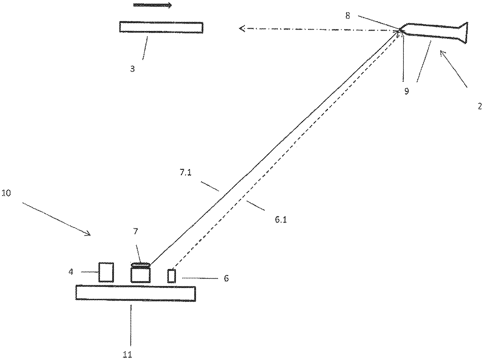
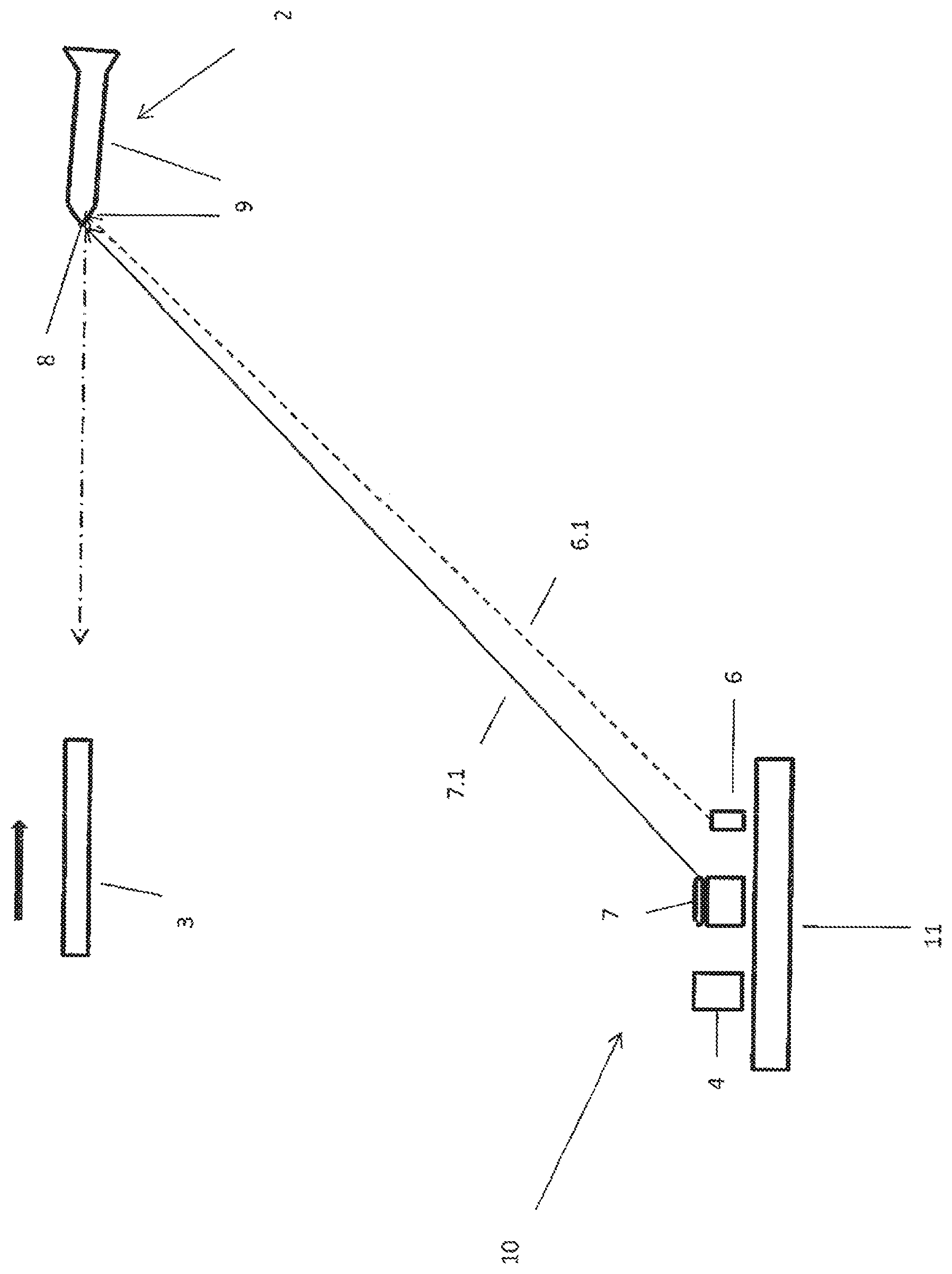
The FIGURE shows a block diagram of a defense system 10 for threat defense. The threat 2 is an incoming missile in the present exemplary embodiment. For the threat defense, in the present exemplary embodiment a rocket (missile) 3 having an IR seeker is provided, which can be discharged from a weapon (launcher).
The defense system 10 comprises at least one detection device 4, which can be a radar or an electro-optical system. A laser 6 can be integrated as an illumination laser into the defense system 10. A laser weapon system is identified by 7, which is to better characterize (identify) the threat 2 according to the invention. The laser weapon system 7 is a high-performance laser in this case. A fire control of the defense system 10 is not shown in greater detail, since it is known. Incoming signals, data, etc., for example, of the detection device 4, etc. are processed via this fire control and output as signals or data to the actuators incorporated in the defense system 10, for example, a weapon not shown in greater detail, the laser 6 or the laser weapon system 7, etc.
The laser weapon system 7 consists at least of a laser unit, a laser (high-performance laser), such as single-resonator oscillator, or master oscillator power amplifier (MOPA), and associated optical units (not shown in greater detail).
By means of the detection device 4, a space to be monitored around an object 11 to be secured (stationary, movable, or moving) is regularly searched and monitored for incoming missiles 2.
With recognition of the threat, the emission of the countermeasure can be initiated by the fire control and the rockets 3 can be sent toward the missile 2 in a known manner. The launcher (not shown in greater detail here) required for this purpose can also be located remotely from the object 11, but is to be functionally connected to the fire control of the defense system 10.
At the point in time of the detection of the threat 2, a target tracking system (not shown in greater detail) can also switch thereto.
In order that a single shot eliminates the missile 2, it is provided that a clearly recognizable target (missile 2) faces the rocket 3. This missile 2 is supposed to stand out better from the background for this purpose. This better standing out is implementable by at least punctiform heating on the threat. In practice, a temperature difference of approximately 2.degree. C. has been shown to be sufficient. At an ambient temperature of 15.degree. C., heating to 17.degree. C. would be sufficient and should be achieved.
As soon as the detection device 4 has detected the incoming missile 2, the option exists that the illumination laser 6 switches to the missile 2 and fixes its laser radiation 6.1 thereon. This fixed point 8 on the missile 2 is preferably located in the visible region of the missile 2 (in general the missile tip). The fixed point 8 can be located in this case on sensitive structural parts of the missile 2, preferably on the tip (ogive, hood), tail unit, etc. of the missile 2. The fixed point 8 can be used by the laser weapon system 7 to align its laser beam 7.1 on the missile 2.
With the aid of the laser beam 7.1, the missile 2 is heated or warmed on its surface 9, preferably in the region of the tip (ogive, hood). The missile 2 thus becomes warmer at this point and images a clearly recognizable spot on the missile 2 for the IR seeker of the rocket 3. The rocket 3 can accurately eliminate the missile 2.
The method can also be applied to stationary threats/targets.
The invention being thus described, it will be obvious that the same may be varied in many ways. Such variations are not to be regarded as a departure from the spirit and scope of the invention, and all such modifications as would be obvious to one skilled in the art are to be included within the scope of the following
* * * * *
D00000
D00001
XML
uspto.report is an independent third-party trademark research tool that is not affiliated, endorsed, or sponsored by the United States Patent and Trademark Office (USPTO) or any other governmental organization. The information provided by uspto.report is based on publicly available data at the time of writing and is intended for informational purposes only.
While we strive to provide accurate and up-to-date information, we do not guarantee the accuracy, completeness, reliability, or suitability of the information displayed on this site. The use of this site is at your own risk. Any reliance you place on such information is therefore strictly at your own risk.
All official trademark data, including owner information, should be verified by visiting the official USPTO website at www.uspto.gov. This site is not intended to replace professional legal advice and should not be used as a substitute for consulting with a legal professional who is knowledgeable about trademark law.