Integrated aircraft propulsion system
Rice , et al. March 16, 2
U.S. patent number 10,947,929 [Application Number 16/017,647] was granted by the patent office on 2021-03-16 for integrated aircraft propulsion system. This patent grant is currently assigned to ROLLS-ROYCE NORTH AMERICAN TECHNOLOGIES INC.. The grantee listed for this patent is ROLLS ROYCE NORTH AMERICAN TECHNOLOGIES INC.. Invention is credited to William B. Bryan, Richard K. Keller, Edward C. Rice.


View All Diagrams
| United States Patent | 10,947,929 |
| Rice , et al. | March 16, 2021 |
Integrated aircraft propulsion system
Abstract
An integrated propulsion system comprising at least two gas turbine engines, at least one fan, and a transmission assembly coupling the at least two gas turbine engines to the at least one fan wherein the at least two gas turbine engines are disposed within a main body of an airframe comprising the main body and a pair of wings, and wherein the number of gas turbine engines is greater than the number of fans.
| Inventors: | Rice; Edward C. (Indianapolis, IN), Keller; Richard K. (Indianapolis, IN), Bryan; William B. (Indianapolis, IN) | ||||||||||
|---|---|---|---|---|---|---|---|---|---|---|---|
| Applicant: |
|
||||||||||
| Assignee: | ROLLS-ROYCE NORTH AMERICAN
TECHNOLOGIES INC. (Indianapolis, IN) |
||||||||||
| Family ID: | 1000005423950 | ||||||||||
| Appl. No.: | 16/017,647 | ||||||||||
| Filed: | June 25, 2018 |
Prior Publication Data
| Document Identifier | Publication Date | |
|---|---|---|
| US 20180306143 A1 | Oct 25, 2018 | |
Related U.S. Patent Documents
| Application Number | Filing Date | Patent Number | Issue Date | ||
|---|---|---|---|---|---|
| 14837079 | Aug 27, 2015 | ||||
| Current U.S. Class: | 1/1 |
| Current CPC Class: | B64D 27/20 (20130101); F02K 3/12 (20130101); Y02T 50/40 (20130101) |
| Current International Class: | F02K 3/12 (20060101); B64D 27/20 (20060101) |
References Cited [Referenced By]
U.S. Patent Documents
| 2601194 | June 1952 | Whittle |
| 2929207 | March 1960 | Peterson |
| 3025025 | March 1962 | Duttmann |
| 3442493 | May 1969 | Smith, Jr. |
| 3517509 | June 1970 | Bayati |
| 3659422 | May 1972 | Hope |
| 3739580 | June 1973 | Bland et al. |
| 3861822 | January 1975 | Wanger |
| 3946554 | March 1976 | Neumann |
| 4000868 | January 1977 | Gregor |
| 4089493 | May 1978 | Paulson |
| 4149374 | April 1979 | Barchenko |
| 4235397 | November 1980 | Compton |
| 4254619 | March 1981 | Giffin, III et al. |
| 4705452 | November 1987 | Karadimas |
| 4791783 | December 1988 | Neitzel |
| 4912924 | April 1990 | Stockwell |
| 5180119 | January 1993 | Picard |
| 5314301 | May 1994 | Knight |
| 5464175 | November 1995 | Short |
| 5472314 | December 1995 | Delonge et al. |
| 5518363 | May 1996 | Theis |
| 5520511 | May 1996 | Loudet et al. |
| 5855340 | January 1999 | Bacon |
| 5911679 | June 1999 | Farrell et al. |
| 5947412 | September 1999 | Berman |
| 6279852 | August 2001 | Dusserre-Telmon |
| 6379110 | April 2002 | McCormick et al. |
| 6415597 | July 2002 | Futamura et al. |
| 6688552 | February 2004 | Franchet et al. |
| 6792746 | September 2004 | Saito et al. |
| 6834495 | December 2004 | Saito et al. |
| 6845606 | June 2005 | Franchet et al. |
| 7033132 | April 2006 | Gharib |
| 7059129 | June 2006 | Zollinger et al. |
| 7114911 | October 2006 | Martin et al. |
| 7134631 | November 2006 | Loth |
| 7140188 | November 2006 | Hosokawa et al. |
| 7444802 | November 2008 | Parry |
| 7464533 | December 2008 | Wollenweber |
| 7491030 | February 2009 | Pinera et al. |
| 7549839 | June 2009 | Carroll et al. |
| 7631483 | December 2009 | Mani et al. |
| 7665689 | February 2010 | McComb |
| 7669404 | March 2010 | Samimy et al. |
| 7828516 | November 2010 | Hartmann et al. |
| 7837436 | November 2010 | Corsmeier et al. |
| 7877980 | February 2011 | Johnson |
| 7887287 | February 2011 | Yanagi et al. |
| 8011882 | September 2011 | McMillan |
| 8152095 | April 2012 | Cazals et al. |
| 8161728 | April 2012 | Kupratis |
| 8336289 | December 2012 | Roberge |
| 8393857 | March 2013 | Copeland et al. |
| 8468795 | June 2013 | Suciu et al. |
| 8529188 | September 2013 | Winter |
| 8562284 | October 2013 | Bradbrook |
| 8578700 | November 2013 | Khakhar |
| 8657561 | February 2014 | Buffone et al. |
| 8770921 | July 2014 | Huber et al. |
| 8813907 | August 2014 | Tanaka et al. |
| 8862362 | October 2014 | Teicholz et al. |
| 8915703 | December 2014 | Mohammed |
| 9003768 | April 2015 | Suciu et al. |
| 9016041 | April 2015 | Baughman et al. |
| 9017038 | April 2015 | Pelley et al. |
| 9239011 | January 2016 | Jones |
| 9297270 | March 2016 | Suciu et al. |
| 9540113 | January 2017 | Gukeisen |
| 9701395 | July 2017 | Veilleux, Jr. |
| 10435163 | October 2019 | Gallet |
| 2002/0190158 | December 2002 | Franchet et al. |
| 2003/0146344 | August 2003 | Saito |
| 2006/0011780 | January 2006 | Brand |
| 2008/0131268 | June 2008 | Guemmer |
| 2010/0166543 | July 2010 | Carroll |
| 2010/0329844 | December 2010 | Bradbrook |
| 2011/0146289 | June 2011 | Baughman |
| 2011/0167791 | July 2011 | Johnson et al. |
| 2011/0167792 | July 2011 | Johnson et al. |
| 2011/0167831 | July 2011 | Johnson |
| 2011/0176913 | July 2011 | Wassynger et al. |
| 2011/0252808 | October 2011 | McKenney et al. |
| 2013/0019608 | January 2013 | Jones |
| 2013/0223991 | August 2013 | Suciu et al. |
| 2013/0323013 | December 2013 | Mercier et al. |
| 2014/0090388 | April 2014 | Hasel |
| 2014/0252161 | September 2014 | Gukeisen |
| 2014/0260180 | September 2014 | Kupratis et al. |
| 2014/0345253 | November 2014 | Dawson et al. |
| 2015/0102156 | April 2015 | Devenyi |
| 2015/0121838 | May 2015 | Suciu et al. |
| 2015/0233302 | August 2015 | Levasseur et al. |
| 2015/0291285 | October 2015 | Gallet |
| 2017/0057649 | March 2017 | Rice |
| 2018/0281979 | October 2018 | Reigner |
| 2019/0382123 | December 2019 | Schwarz |
Other References
|
Requirement for Restriction/Election, issued in U.S. Appl. No. 14/837,079, dated Nov. 7, 2016, pp. 1-9, U.S. Patent and Trademark Office, Alexandria, VA. cited by applicant . Non-Final Office Action, issued in U.S. Appl. No. 14/837,079, dated May 12, 2017, pp. 1-10, U.S. Patent and Trademark Office, Alexandria, VA. cited by applicant . Final Office Action, issued in U.S. Appl. No. 14/837,079, dated Sep. 7, 2017, pp. 1-10, U.S. Patent and Trademark Office, Alexandria, VA. cited by applicant . Non-Final Office Action, issued in U.S. Appl. No. 14/837,079, dated Dec. 11, 2017, pp. 1-8, U.S. Patent and Trademark Office, Alexandria, VA. cited by applicant. |
Primary Examiner: Sanderson; Joseph W
Attorney, Agent or Firm: Brinks Gilson & Lione
Parent Case Text
RELATED APPLICATIONS
This application is a divisional of U.S. patent application Ser. No. 14/837,079, filed 27 Aug. 2015, first named inventor: Edward C. Rice, and is related to applications U.S. patent application Ser. No. 14/837,190, filed 27 Aug. 2015, first named inventor: Edward C. Rice; U.S. patent application Ser. No. 14/837,302, filed 27 Aug. 2015, first named inventor: Edward C. Rice; U.S. patent application Ser. No. 14/837,557, filed 27 Aug. 2015, first named inventor: Edward C. Rice; U.S. patent application Ser. No. 14/837,942, filed on 27 Aug. 2015, first named inventor: Edward C. Rice; U.S. patent application Ser. No. 14/837,987, filed 27 Aug. 2015, first named inventor: Edward C. Rice; U.S. patent application Ser. No. 14/837,031, filed 27 Aug. 2015, first named inventor: William Barry Bryan; U.S. patent application Ser. No. 14/838,027, filed 27 Aug. 2015, first named inventor: Edward C. Rice; and U.S. patent application Ser. No. 14/838,067, filed 27 Aug. 2015, first named inventor: Edward C. Rice. The entirety of each of these prior applications are hereby incorporated by reference.
Claims
The invention claimed is:
1. An aircraft with an integrated propulsion system wherein a number of gas turbine engines and a number of fans consists of two gas turbine engines and one fan, the system comprising: a transmission assembly coupling a first of said two gas turbine engines and a second of said two gas turbine engine to said fan; a fan passage in fluid communication with the fan, the fan passage defined between a fan inlet duct and a fan exhaust duct; and at least one gas turbine engine passage in fluid communication with one of the two gas turbine engines, the at least one gas turbine engine passage defined between an inlet duct of the one gas turbine engine and an exhaust duct of the one gas turbine engine; wherein the fan passage and the at least one gas turbine engine passage are exclusive of one another; the fan passage and the at least one gas turbine engine passage being at least partially defined within a fuselage of the aircraft, wherein the inlet duct of the one gas turbine engine is on a first side of the fuselage, and the fan inlet duct is on a second side of the fuselage, wherein the second side of the fuselage is a top side or a bottom side of the fuselage, wherein the top side is the side of the fuselage on which a cockpit of the aircraft is located and the bottom side of the fuselage is the side of the fuselage opposite the top side.
2. The system of claim 1, wherein said first gas turbine engine, said second gas turbine engine, and said fan each have an exclusive air flow duct.
3. The system of claim 2, wherein the exclusive air flow duct of said fan comprises the fan inlet duct, the fan exhaust duct, and a thrust vectoring mechanism.
4. The system of claim 3, wherein the thrust vectoring mechanism is coupled to the fan exhaust duct, the thrust vectoring mechanism configured to vector an exhaust of the fan.
5. The system of claim 3, wherein each of said exclusive air flow ducts partially extend radially outward from a main body of the fuselage.
6. The system of claim 1 wherein said transmission assembly comprises a gearbox.
7. The system of claim 1 wherein said transmission assembly comprises a clutch.
8. The system of claim 1, wherein the fan passage and the at least one gas turbine engine passage each have a respective axis of rotation that can form an angle with a center axis of the fuselage.
9. The system of claim 1, wherein the transmission assembly is configured to distribute an output power of the first gas turbine engine and the second gas turbine engine to the fan.
10. An aircraft with a propulsion system comprising: a first gas turbine engine installed on a first side of an aircraft body and a second gas turbine engine installed on a second side of said aircraft body; and a fan unit installed on a top side of said aircraft body or a bottom side of the aircraft body, wherein the top side is the side of the aircraft body on which a cockpit of the aircraft is located and the bottom side is the side of the aircraft body opposite the top side, said fan unit coupled to said first gas turbine engine and said second gas turbine engine by a transmission assembly comprising a clutch and more than one rotating linkages, wherein each of said first gas turbine engine and said second gas turbine engine are in fluid communication with a respective exclusive engine duct comprising an engine inlet duct and an engine exhaust duct, and wherein said fan unit is in fluid communication with an exclusive fan duct comprising a fan inlet duct and a fan exhaust duct, the exclusive fan duct and each of the exclusive engine ducts are at least partially defined within the aircraft body, wherein the engine inlet duct of the first gas turbine engine is on the first side of the aircraft body, the engine inlet duct of the second gas turbine engine is on the second side of the aircraft body, and the fan inlet duct is on the top side of the aircraft body or the bottom side of the aircraft body.
11. The system of claim 10, wherein the fan inlet duct and the engine inlet duct of at least one of the first gas turbine engine or the second gas turbine engine are separated by the aircraft body.
12. The system of claim 10, wherein the exclusive fan duct defines a first airflow and each of the exclusive engine ducts define a second air flow and a third air flow, wherein said first airflow, said second air flow, and said third air flow are exclusive of each other.
13. The system of claim 10, wherein the fan inlet duct and the engine inlet duct of at least one of the first gas turbine engine or the second gas turbine engine opens to ambient air.
14. The system of claim 10, wherein the fan exhaust duct can be coupled with a thrust vectoring system.
15. The system of claim 10, wherein said fan unit, said first gas turbine engine, and said second gas turbine engine each have a respective axis of rotation that can form an angle with a center axis of the aircraft body.
Description
FIELD OF THE DISCLOSURE
The present disclosure relates generally to aircraft propulsion, and more specifically to integrated propulsion systems for aircraft comprising gas turbine engines and fans.
BACKGROUND
Turbofan engines provide propulsion to a wide range of aircraft. A typical turbofan engine comprises an inlet fan, a compressor fan, a combustor, a high-pressure turbine, and a low-pressure turbine. Some air which passes through the inlet fan bypasses the compressor fan, combustor, and high- and low-pressure turbines.
In some applications, conventional turbofan engines are too costly in terms of volume, weight, and packaging or placement within an airframe. Due to the numerous performance requirements and applications of modern aircraft, more efficient propulsion systems are in demand which require less volume, weigh less, and/or provide greater packaging and placement options within an airframe.
The present application discloses one or more of the features recited in the appended claims and/or the following features which, alone or in any combination, may comprise patentable subject matter.
According to an aspect of the present disclosure, an integrated propulsion system comprises at least two gas turbine engines, at least one fan, and a transmission assembly coupling the at least two gas turbine engines to the at least one fan wherein the at least two gas turbine engines are disposed within a main body of an airframe comprising the main body and a pair of wings, and wherein the number of gas turbine engines is greater than the number of fans. In some embodiments each of the gas turbine engines having an exclusive engine air flow duct comprising an engine inlet and an engine exhaust. In some embodiments the fan has an exclusive fan air flow duct comprising a fan inlet and a fan exhaust. In some embodiments the fan exhaust comprises a fan exhaust duct and a thrust vectoring mechanism. In some embodiments each of the engine inlet and the fan inlet comprise an inlet duct extending radially outward from the main body of the airframe. In some embodiments the at least one fan is mounted within the main body of the airframe. In some embodiments the transmission assembly comprises a clutch mechanism. In some embodiments the output power of the at least two gas turbine engines is distributed to the at least one fan when the clutch mechanism is engaged. In some embodiments the fan has a fan exhaust duct and each of the gas turbine engines having an engine inlet duct connected to the fan exhaust duct.
According to another aspect of the present disclosure, an integrated propulsion system consists of a first gas turbine engine and a second gas turbine engine, a fan, and a transmission assembly coupling the first gas turbine engine and the second gas turbine engine to the fan. In some embodiments the first gas turbine engine, the second gas turbine engine, and the fan each have an exclusive air flow duct. In some embodiments the air flow duct of the fan comprises an inlet duct, exhaust duct, and thrust vectoring mechanism. In some embodiments of the first gas turbine engine, the second gas turbine engine, and the fan have an axis of rotation which is parallel to a central axis of a main body of an airframe. In some embodiments the first gas turbine engine and the second gas turbine engine an axis of rotation which is disposed at an angle to a central axis of a main body of an airframe. In some embodiments the fan has an axis of rotation normal to a central axis of a main body of an airframe. In some embodiments the transmission assembly comprises a gearbox. In some embodiments the transmission assembly comprises a clutch.
According to another aspect of the present disclosure, an integrated propulsion system comprises a first gas turbine engine and a second gas turbine engine, each of the first gas turbine engine and the second gas turbine engine mounted within an airframe and having an exclusive air flow duct comprising an engine inlet duct and an engine exhaust duct; a fan mounted to the airframe and having an exclusive air flow duct comprising a fan inlet duct and a fan exhaust duct; and a transmission assembly coupling the first gas turbine engine and the second gas turbine engine to the fan; wherein the airframe comprises a main body and a pair of laminar flow wings and wherein the transmission assembly distributes power from the first gas turbine engine and the second gas turbine engine to the fan and a second load. In some embodiments the second load is one of a lift rotor, a propeller, or a generator. In some embodiments the fan exhaust duct comprises a thrust vectoring mechanism.
According to yet another aspect of the present disclosure, a method is provided of reducing drag in a turbofan aircraft. The method comprises reducing the required cross-sectional area of an aircraft body and reducing the total weight of the aircraft propulsion system by: disposing a first gas turbine engine on a first side of the aircraft body and a second gas turbine engine on a second side of the aircraft body; disposing a fan unit on the aircraft body, the fan unit coupled to the first gas turbine engine and the second gas turbine engine by a transmission assembly comprising a clutch and more than one rotating linkages; venting each of the first gas turbine engine and the second gas turbine engine via a respective exclusive engine duct comprising an engine inlet duct and an engine exhaust duct; and venting the fan unit via an exclusive fan duct comprising a fan inlet duct and a fan exhaust duct. In some embodiments the fan exhaust duct includes a thrust vectoring mechanism. In some embodiments each of the first gas turbine engine, the second gas turbine engine, and the fan unit have an axis of rotation which is parallel to a central axis of a main body of an airframe.
BRIEF DESCRIPTION OF THE DRAWINGS
The following will be apparent from elements of the figures, which are provided for illustrative purposes and are not necessarily to scale.
FIG. 1 is a block schematic diagram of a typical turbofan engine.
FIG. 2 is a block schematic diagram of a turbofan engine in which a fan is physically separated from the engine core and linked via transmission mechanism in accordance with some embodiments of the present disclosure.
FIG. 3A is a block diagram of an integrated propulsion system in accordance with some embodiments of the present disclosure.
FIG. 3B is a detailed block diagram of the integrated propulsion system in FIG. 3A, in accordance with some embodiments of the present disclosure.
FIG. 4 is an isometric view of an aircraft having integrated propulsion system in accordance with some embodiments of the present disclosure.
FIG. 5 is a side profile view of the main body of an aircraft in accordance with some embodiments of the present disclosure.
FIG. 6A is a radial cross-sectional view of the main body at the inlet ducts in accordance with some embodiments of the present disclosure.
FIG. 6B is a radial cross-sectional view of the main body at the engines in accordance with some embodiments of the present disclosure.
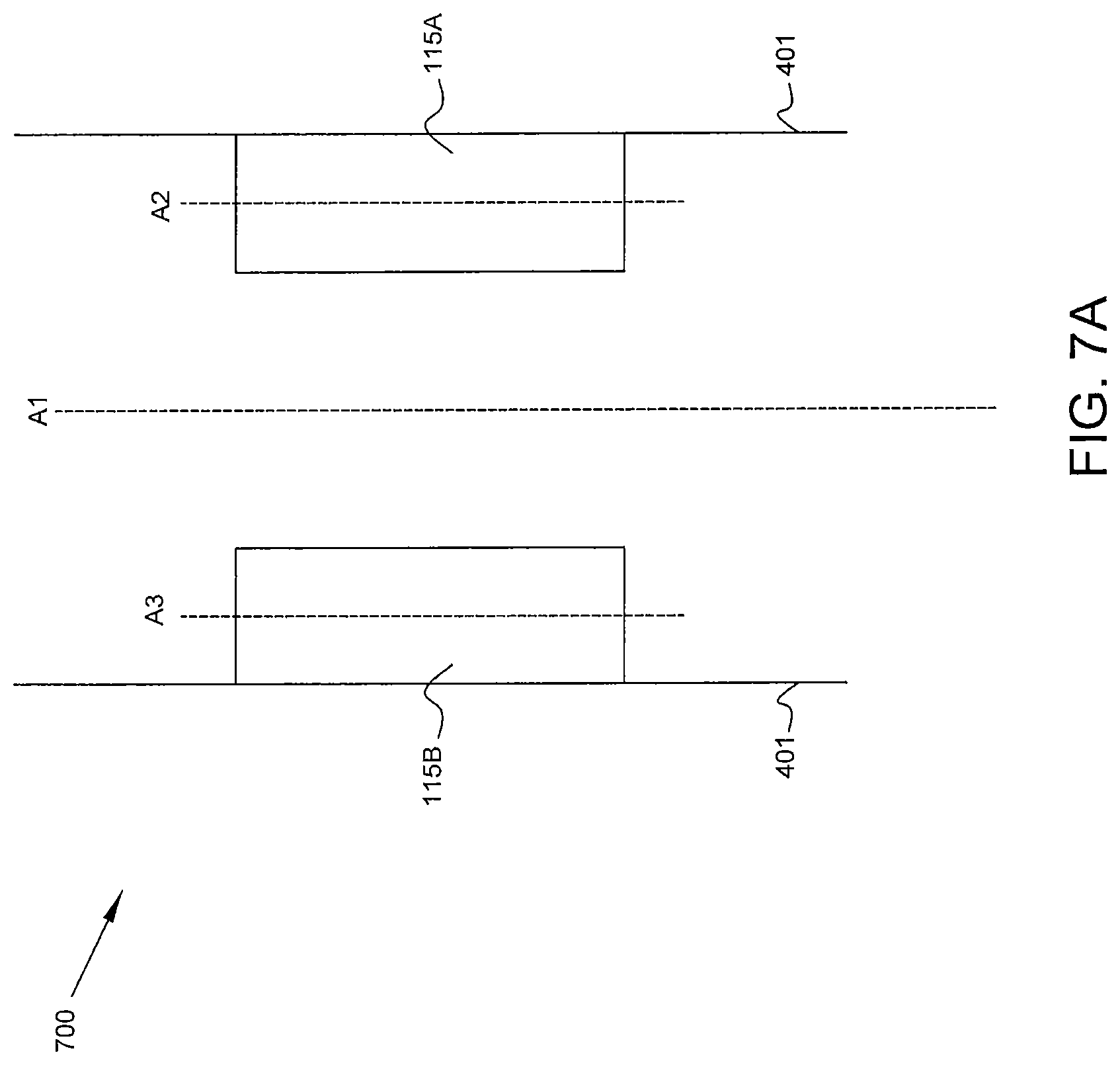
FIG. 7A is a top cross-sectional view of the main body in accordance with some embodiments of the present disclosure.
FIG. 7B is a top cross-sectional view of the main body in accordance with some embodiments of the present disclosure.
FIG. 8A is a side cross-sectional view of the main body in accordance with some embodiments of the present disclosure.
FIG. 8B is a side cross-sectional view of the main body in accordance with some embodiments of the present disclosure.
FIG. 9A is a detailed block diagram of an integrated propulsion system in accordance with some embodiments of the present disclosure.
FIG. 9B is a side profile view of the main body of an aircraft having the integrated propulsion system of FIG. 9A, in accordance with some embodiments of the present disclosure.
While the present disclosure is susceptible to various modifications and alternative forms, specific embodiments have been shown by way of example in the drawings and will be described in detail herein. It should be understood, however, that the present disclosure is not intended to be limited to the particular forms disclosed. Rather, the present disclosure is to cover all modifications, equivalents, and alternatives falling within the spirit and scope of the disclosure as defined by the appended claims.
DETAILED DESCRIPTION
For the purposes of promoting an understanding of the principles of the disclosure, reference will now be made to a number of illustrative embodiments illustrated in the drawings and specific language will be used to describe the same.
This disclosure presents embodiments to overcome the aforementioned deficiencies of conventional turbofan engines. More specifically, this disclosure is directed to an integrated propulsion system having a smaller volume, lighter weight, and greater range of placement options within an airframe when compared to conventional turbofan engines. The integrated propulsion system comprises gas turbine engines and at least one fan linked by a transmission assembly.
FIG. 1 is a block schematic diagram of a typical turbofan engine 100. The turbofan engine 100 comprises an inlet fan 101, a compressor 103, a combustor 105, a high-pressure turbine 107, a low-pressure turbine 109, a bypass region 111, and an exhaust mixing region 113. The inlet fan 101 is mounted to the front of the compressor 103. The engine core 115 is defined as the compressor 103, combustor 105, high-pressure turbine 107, and low-pressure turbine 109.
Air enters the turbofan engine 100 via inlet fan 101. A first portion of the air flows through the bypass region 111 and into the exhaust mixing region 113. A second portion of the air flows into the compressor 103 where it is pressurized, then into the combustor where it is mixed with fuel and ignited. The ratio of the first portion of air flowing through the bypass region 111 to the second portion of air flowing through the engine core 115 is referred to as the bypass ratio.
The hot, high-pressure combustion gasses are directed sequentially into the high-pressure turbine 107 and low-pressure turbine 109, causing each turbine 107, 109 to rotate about a shaft which is connected to and drives the compressor 103 and the inlet fan 101. In multiple-spool designs, more than one concentric shafts are used to separately rotate various components. For example, in a standard two-spool turbofan engine the high-pressure turbine 107 and compressor 103 are connected using a first common shaft while the low-pressure turbine 109 and inlet fan 101 are connected using a second common shaft.
In the turbofan engine 100 presented in FIG. 1, a first portion of thrust is created by the engine 100 is created by the inlet fan 101 sending airflow through the bypass region 111, while a second portion of thrust is created by the exhaust of the engine core 115.
FIG. 2 is a block schematic diagram of a turbofan engine 200 in which a fan 209 is physically separated from the engine core 115 yet linked via transmission mechanism 205. An engine inlet duct 201 and engine exhaust duct 203 are connected on either side of the engine core 115. In some embodiments, fan 209 receives inlet airflow with the engine inlet duct 201. In some embodiments, fan 209 sends exhaust airflow to the engine exhaust duct 203. However, in other embodiments such as illustrated in FIGS. 4, 5, and 6 and described below, fan 209 is connected to a fan inlet duct 405 and fan exhaust duct 409 which are distinct from the engine inlet duct 201 and engine exhaust duct 203.
Transmission mechanism 205 transferred shaft power from engine core 115 to fan 209. In some embodiments, transmission mechanism 205 includes a clutch mechanism, a gearbox, a beveled gear, and/or an angled gearbox. In those embodiments in which transmission mechanism 205 comprises a clutch mechanism, output power of the first engine core 115A and second engine core 115B is distributed to the fan when the clutch mechanism is engaged.
FIG. 3A is a block diagram of an integrated propulsion system 300 comprising a fan 209 connected to a first engine core 115A and second engine core 115B via at least one transmission shaft 303 and a gearbox 301. In some embodiments, an additional transmission shaft 305 is output from gearbox 301 to drive an alternative means of propulsion.
FIG. 3B provides a more detailed block schematic diagram of the integrated propulsion system 300. A first engine core 115A comprises a first compressor 103A, first combustor 105A, first high-pressure turbine 107A, and first low-pressure turbine 109A. First engine core 115A is connected to a first engine inlet duct 201A and first engine exhaust duct 203A. A second engine core 115B comprises a second compressor 103B, second combustor 105B, second high-pressure turbine 107B, and second low-pressure turbine 109B. Second engine core 115B is connected to a second engine inlet duct 201B and second engine exhaust duct 203B.
In some embodiments, as illustrated in FIG. 3B, each of first engine core 115A and second engine core 115B have an exclusive engine inlet duct (201A, 201B) and engine exhaust duct (203A, 203B). In other embodiments, one or both of the engine inlet ducts and engine exhaust ducts can be combined as a non-exclusive, shared duct. For example, first engine core 115A and second engine core 115B will in some embodiments share a common nonexclusive engine inlet duct while retaining separate engine exhaust ducts. Similarly, first engine core 115A and second engine core 115B will in some embodiments share a common nonexclusive engine inlet duct and share a common nonexclusive engine exhaust duct. Finally, in some embodiments first engine core 115A and second engine core 115B will share a common nonexclusive engine exhaust duct while retaining separate engine inlet ducts.
Fan 209 is supplied with shaft power from first engine core 115A and second engine core 115B via transmission shafts 303A, 303B, and 303C. In some embodiments, transmission shafts 303 pass through a gearbox 301. In some embodiments, gearbox 301 further comprises a clutch mechanism for selectively engaging transmission shaft 303A from first engine core 115A, transmission shaft 303B from second engine core 115B, or both. Transmission shaft 303C couples gearbox 301 to fan 209. In some embodiments an additional transmission shaft 305 is output from gearbox 301 to drive an alternative load, such as an alternative means of propulsion, a lift rotor, a propeller, or a generator.
As with the embodiment of FIG. 2 described above, in some embodiments, fan 209 receives inlet airflow from the first engine inlet duct 201A or second engine inlet duct 201B or a combination of the two. In some embodiments, fan 209 sends exhaust airflow to the first engine exhaust duct 203A or second engine exhaust duct 203B or a combination of the two. However, in other embodiments such as illustrated in FIGS. 4, 5, and 6 and described below, fan 209 is connected to a fan inlet duct 405 which is distinct from the first engine inlet duct 201A and second engine inlet duct 201B. Fan 209 is also connected to fan exhaust duct 409 which is distinct from first engine exhaust duct 203A and second engine exhaust duct 203B.
The integrated propulsion system 300 illustrated in FIGS. 3A and 3B is an improvement over a two turbofan engine configuration because using a single fan 209 requires less volume than using two fans, reduces overall system weight and drag, and tends to be more fuel efficient. In some embodiments, the single fan 209 is larger than a fan 101 mounted to a compressor 103 in a standard turbofan engine 100.
FIG. 4 is an isometric view of an aircraft 400 having integrated propulsion system 300. FIG. 4 illustrates a possible placement of the integrated propulsion system 300 on a conventional body aircraft 400. Specifically, aircraft 400 comprises a main body 401 of the airframe and a pair of laminar flow wings 403 extending from the main body 401. This conventional body aircraft 400 contrasts with alternative aircraft bodies such as a blended wing body or flying wing. The reduced volume of the integrated propulsion system 300 lends itself to smaller packaging and easier placement on a conventional body aircraft 400.
As illustrated in FIG. 4, fan 209 is contained within a fan shroud 407 and connected to a fan inlet duct 405 and fan exhaust duct 409 which are distinct from any engine ducting. A first engine inlet duct 201A is shown on the side of aircraft 400.
In the illustrated embodiment, the fan inlet duct 405, fan 209, and fan exhaust duct 409 are positioned on the main body 401 above the wings 403. In some embodiments, the fan inlet duct 405, fan 209, and fan exhaust duct 409 are positioned further forward or further aft than the illustrated position. In some embodiments, the fan inlet duct 405, fan 209, and fan exhaust duct 409 are more elongated than illustrated, resulting in fan ducting which covers a longer portion of aircraft 400. Finally, in some embodiments the fan inlet duct 405, fan 209, and fan exhaust duct 409 are positioned on the underside of main body 401.
Similarly, in the illustrated embodiment the first engine inlet duct 201A is positioned on the main body 401 beneath a wing 403. In some embodiments, the first engine inlet duct 201A and second engine inlet duct 201B (not shown in FIG. 4) are positioned further forward or further aft than the illustrated position. In some embodiments, engine inlet ducts 201A, 201B and engine exhaust ducts 203A, 203B are more elongated than illustrated, resulting in engine ducting which covers a longer portion of aircraft 400.
FIG. 5 is a side profile view of the main body 401 of the aircraft 400, illustrating the layout of a portion of the integrated propulsion system 300. As illustrated in FIG. 5, fan 209 is mounted within fan shroud 407 at the top of the main body 401 and connected to the fan inlet duct 405 and fan exhaust duct 409. In some embodiments fan 209 is disposed in a recess 411 in main body 401 to reduce aerodynamic drag. First engine core 115A is disposed inside main body 401 and connected to first engine inlet duct 201A and first engine exhaust duct 203A.
In some embodiments a thrust vectoring mechanism 501 is attached to the aft portion of fan exhaust duct 409. Thrust vectoring mechanism 501 can comprise articulating nozzles, vanes, or paddles.
As illustrated in FIG. 5, in some embodiments fan 209 is mounted above first engine core 115A. In some embodiments, fan 209 is mounted further forward or further aft relative to first engine core 115A. Similarly, in some embodiments first engine core 115A is mounted further forward or further aft relative to fan 209.
FIG. 6A is a cross-sectional view of the main body 401 at the inlet ducts. A first engine inlet duct 201A, second engine inlet duct 201B, and fan inlet duct 405 are each mounted radially outward on the external main body 401 of an aircraft 400. As discussed above, in some embodiments fan inlet duct 405 is disposed at the top of main body 401; however, in other embodiments fan inlet duct 405 is disposed at the bottom of main body 401.
FIG. 6B is a cross-sectional view of the main body 401 at the engines and fan. FIG. 6B illustrates the first engine core 115A and second engine core 115B are disposed within main body 401 of aircraft 400. Fan 209 is disposed at the top of main body 401. In some embodiments, fan 209 is disposed in a recess 411 in main body 401 to reduce aerodynamic drag. As discussed above, in some embodiments fan 209 is disposed at the bottom of main body 401.
FIGS. 7A and 7B illustrate various embodiments regarding the placement of first engine core 115A and second engine core 115B. An airframe axis A1 extends through the center of main body 401, parallel with the length of the exterior of main body 401. In a first configuration 700, first engine core 115A and second engine core 115B are disposed within main body 401 such that a first engine core axis A2 and second engine core axis A3 are parallel to airframe axis A1. In a second configuration 750, first engine core 115A and second engine core 115B are disposed within main body 401 such that first engine core axis A2 and second engine core axis A3 are disposed at an angle .theta.1 to airframe axis A1.
In some embodiments first engine core axis A2 and second engine core axis A3 are defined as the axes of rotation for the respective gas turbine engine cores.
In some embodiments, first engine core 115A and second engine core 115B are disposed along a radial edge of main body 401. In other embodiments, first engine core 115A and second engine core 115B are disposed radially inward from the exterior skin of main body 401. In some embodiments, angle .theta.1 is between 5 and 25 degrees.
Similarly, FIGS. 8A and 8B illustrate various embodiments regarding the placement of fan 209. In a first configuration 800 illustrated in FIG. 8A, fan 209 has a fan axis A4 which is parallel to airframe axis A1. In a second configuration 850 illustrated in FIG. 8B, fan 209 has a fan axis A4 disposed at an angle .theta.2 to airframe axis A1. In some embodiments, angle .theta.2 is between 5 and 30 degrees. In other embodiments, angle .theta.2 is between 45 and 90 degrees. In other embodiments, fan axis A4 is normal to airframe axis A1. In still other embodiments, angle .theta.2 is variable based on a control system for controlling fan 209 angle.
An additional embodiment of an integrated propulsion system 900 is presented in FIGS. 9A and 9B. FIG. 9A is a detailed block diagram of an integrated propulsion system 900, while FIG. 9B is a side profile view of the main body of an aircraft 401 having integrated propulsion system 900.
Integrated propulsion system 900 comprises a fan 209, first engine core 115A, and second engine core 115B. Fan 209 is contained within a fan shroud 407 and is connected to a fan inlet duct 405 and fan exhaust duct 409. First engine core 115A is connected to a first engine inlet duct 201A and first engine exhaust duct 203A, while second engine core 115B is connected to a second engine inlet duct 203A and second engine exhaust duct 203B. As in the embodiment illustrated in FIGS. 3A and 3B, fan 209 is coupled to first engine core 115A and second engine core 115B via transmission shafts 303A, 303B, and 303C, and a gearbox 301. In some embodiments, an additional transmission shaft 305 is output from gearbox 301 to drive an alternative means of propulsion. In some embodiments a plurality of transmission shafts are referred to collectively as a transmission assembly.
In integrated propulsion system 900 first engine inlet duct 201A and second engine inlet duct 201B draw air from fan exhaust duct 409. Because only a portion of fan exhaust is needed to meet the air intake requirements of first engine core 115A and second engine core 115B, some fan exhaust is discharged from the fan exhaust duct 409 into the surrounding atmosphere.
The illustrated embodiment of FIGS. 9A and 9B enables first engine core 115A and second engine core 115B to draw inlet air at a higher pressure than atmospheric pressure, this configuration allows first engine core 115A and second engine core 115B to produce a higher power output and operate more efficiently. Thus this embodiment is more similar thermodynamically to a conventional turbofan engine than the embodiments of FIGS. 3A and 3B. Additionally, the integrated propulsion system 900 provides advantageous packaging of the system 900 within the main body 401 in some applications.
The disclosed integrated propulsion systems provide numerous advantages over the prior art. The disclosed system requires a smaller volumetric footprint within the airframe because it uses a single fan unit vice multiple fan units or multiple turbofans. In previous configurations which required the use of multiple fan units a significant amount of cargo space was used by the fan units, leading to the use of blended wing body airframes to accommodate the configuration. In contrast, the present disclosure is capable of use with a conventional aircraft body comprising a main body and laminar flow wings extending from the main body. The smaller volumetric footprint also allows for easier packaging within the aircraft, and as a result can lead to use in a smaller cross-sectioned aircraft. The disclosed system additionally has improved drag performance over prior configurations (i.e. reduced aircraft aerodynamic drag) because a single fan unit, even when relatively larger than a fan unit of multiple fan unit configurations, weighs less than multiple fan units and their associated ducting. A smaller cross-sectioned aircraft would also display improved drag performance over prior configurations. Finally, the use of a single, larger fan unit provides greater fuel efficiency than multiple fan configurations.
Although examples are illustrated and described herein, embodiments are nevertheless not limited to the details shown, since various modifications and structural changes may be made therein by those of ordinary skill within the scope and range of equivalents of the claims.
* * * * *
D00000
D00001
D00002
D00003
D00004
D00005
D00006
D00007
D00008
D00009
D00010
D00011
D00012

XML
uspto.report is an independent third-party trademark research tool that is not affiliated, endorsed, or sponsored by the United States Patent and Trademark Office (USPTO) or any other governmental organization. The information provided by uspto.report is based on publicly available data at the time of writing and is intended for informational purposes only.
While we strive to provide accurate and up-to-date information, we do not guarantee the accuracy, completeness, reliability, or suitability of the information displayed on this site. The use of this site is at your own risk. Any reliance you place on such information is therefore strictly at your own risk.
All official trademark data, including owner information, should be verified by visiting the official USPTO website at www.uspto.gov. This site is not intended to replace professional legal advice and should not be used as a substitute for consulting with a legal professional who is knowledgeable about trademark law.