PC blaster game console
Fuchs , et al. March 16, 2
U.S. patent number 10,946,272 [Application Number 16/523,891] was granted by the patent office on 2021-03-16 for pc blaster game console. This patent grant is currently assigned to Arkade, Inc.. The grantee listed for this patent is ARKADE, INC.. Invention is credited to Bob Steven Berns, Joshua Allan Fuchs, Joel Abraham Kort, Charles Michael Seltzer.


| United States Patent | 10,946,272 |
| Fuchs , et al. | March 16, 2021 |
PC blaster game console
Abstract
A portable gaming device includes a game console housing including a handle, a trigger, a screen holder, and a display device coupled to the screen holder. The display device includes a display. The portable gaming device also comprises a processing circuit internally coupled to the game console housing including a processor, a memory, and a network interface, wherein the processing circuit is in communication with the display device. The processing circuit generates a user interface to be displayed on the display, determines a position of the game console housing, and updates the user interface based on the determined position of the game console housing.
| Inventors: | Fuchs; Joshua Allan (Granada Hills, CA), Kort; Joel Abraham (Van Nuys, CA), Seltzer; Charles Michael (Sag Harbor, NJ), Berns; Bob Steven (Van Nuys, CA) | ||||||||||
|---|---|---|---|---|---|---|---|---|---|---|---|
| Applicant: |
|
||||||||||
| Assignee: | Arkade, Inc. (Centennial,
CO) |
||||||||||
| Family ID: | 1000005422426 | ||||||||||
| Appl. No.: | 16/523,891 | ||||||||||
| Filed: | July 26, 2019 |
Prior Publication Data
| Document Identifier | Publication Date | |
|---|---|---|
| US 20210023442 A1 | Jan 28, 2021 | |
| Current U.S. Class: | 1/1 |
| Current CPC Class: | A63F 13/26 (20140902); A63F 13/245 (20140902); A63F 13/837 (20140902) |
| Current International Class: | A63F 9/24 (20060101); A63F 13/245 (20140101); A63F 13/837 (20140101); A63F 13/26 (20140101) |
References Cited [Referenced By]
U.S. Patent Documents
| 5641288 | June 1997 | Zaenglein, Jr. |
| 6020885 | February 2000 | Honda |
| 6054991 | April 2000 | Crane et al. |
| 6184847 | February 2001 | Fateh et al. |
| 6396497 | May 2002 | Reichlen |
| 6684062 | January 2004 | Gosior et al. |
| 6966837 | November 2005 | Best |
| 7319992 | January 2008 | Gaos |
| 8469824 | June 2013 | Farley |
| 8814682 | August 2014 | Yamashita et al. |
| 9041741 | May 2015 | Mabbutt et al. |
| 9110505 | August 2015 | Mastandrea, Jr. |
| 9724601 | August 2017 | Fujita et al. |
| 10021149 | July 2018 | Miller |
| 10075750 | September 2018 | Gordon |
| 10155170 | December 2018 | Ikeda et al. |
| 10471345 | November 2019 | Fuchs |
| 10630773 | April 2020 | Holmes |
| 2002/0128064 | September 2002 | Sobota |
| 2004/0178576 | September 2004 | Hillis et al. |
| 2005/0197178 | September 2005 | Villegas |
| 2007/0021210 | January 2007 | Tachibana |
| 2009/0197679 | August 2009 | Argentar |
| 2009/0280901 | November 2009 | Casparian et al. |
| 2010/0255903 | October 2010 | Bala |
| 2010/0304868 | December 2010 | Zalewski |
| 2012/0302348 | November 2012 | Karacal |
| 2013/0090165 | April 2013 | Shikata et al. |
| 2013/0109473 | May 2013 | Yamashita |
| 2013/0225295 | August 2013 | Lee |
| 2014/0179423 | June 2014 | Deng |
| 2014/0213365 | July 2014 | Cao |
| 2014/0280692 | September 2014 | Cotter |
| 2014/0364063 | December 2014 | Bell |
| 2015/0087414 | March 2015 | Chen et al. |
| 2015/0141145 | May 2015 | Perlman |
| 2015/0229509 | August 2015 | Castine |
| 2015/0238855 | August 2015 | Uy |
| 2016/0321947 | November 2016 | Toronto |
| 2016/0343164 | November 2016 | Urbach et al. |
| 2017/0072307 | March 2017 | Perry et al. |
| 2017/0072309 | March 2017 | Perry et al. |
| 2017/0354864 | December 2017 | Rogers |
| 2017/0354878 | December 2017 | Posin |
| 2017/0354895 | December 2017 | Dornbusch |
| 2017/0365102 | December 2017 | Huston et al. |
| 2018/0104574 | April 2018 | Tager |
| 2018/0143976 | May 2018 | Huston |
| 2018/0264321 | September 2018 | Nir |
| 2019/0081848 | March 2019 | Zou |
| 2019/0270019 | September 2019 | Miura et al. |
| 2019/0321732 | October 2019 | Zimring |
| 2020/0108312 | April 2020 | Chen |
| 206631173 | Nov 2017 | CN | |||
| WO-2007/130582 | Nov 2007 | WO | |||
Other References
|
AR Games Gun. Amazon.com. Online. Jun. 22, 2017. Accessed via the Internet. Accessed May 11, 2020. <URL: https://www.amazon.com/Augmented-Bluetooth-Controller-Portable-Eco-Friend- ly/dp/B0737BSQJ5> (Year: 2017). cited by examiner . What is HDbitT? hdbitt.org. Online. Apr. 16, 2018. Accessed via the Internet. Accessed May 11, 2020. <URL: https://web.archive.org/web/20180416182117/http://www.hdbitt.org:80/what-- is-hdbitt.html> (Year: 2018). cited by examiner . AR Blaster--360.degree. Augmented Reality Video Game--Smart Phone Toy Gun Controller for iPhone & Android phones--Bluetooth 4.2 obtained on Mar. 24, 2020 from url link: https://www.amazon.com/AR-Blaster-Augmented-Reality-Controller-Bluetooth/- dp/B0762T1YYK/ref=pd_sbs_147_4/143-0087825-2430220?_encoding=UTF8&pd_rd_i=- B0762T1YYK&pd_rd_r=ffc5351e-f9ba-4c51-ad97-cb3097544121&pd_rd_w=mx37J&pd_r- d_wg=F34Wd&pf_rd_p=7cd8f929-4345-4bf2-a554-7d7588b3dd5f&pf_rd_r=Z3N3YWQZ71- 5NJRFJQFVY&psc=1&refRID=Z3N3YWQZ715NJRF. cited by applicant . AR Blaster Augmented Reality 360 Degree Portable Gaming VR Gun: Wireless Bluetooth Controller Toy Pistol for iOS Phone and Android Smartphones obtained on Mar. 24, 2020 from url link: https://www.amazon.com/AR-BLASTER-Augmented-Reality-Portable/dp/B07769PM5- L/ref=pd_rhf_eeolp_p_img_5?_encoding=UTF8&psc=1&refRID=34N965YW8TV4Y45CPEC- Q obtained on Mar. 24, 2020. cited by applicant . AR Game Gun Augmented Reality VR Gun Controller Joysticker Gamepad for Video Game with Bluetooth Connecting iOS, Android Smart Phone iPad TV Box Shooting Game obtained on Mar. 24, 2020 from url link: https://www.amazon.com/Augmented-Controller-Joysticker-Bluetooth-Connecti- ng/dp/B06XT11RNW/ref=pd_di_sccai_1/144-3233725-9935121?_encoding=UTF8&pd_r- d_i=B06XT11RNW&pd_rd_r=77ef4782-0163-4631-9e66-216524c94ca3&pd_rd_w=j0PaW&- pd_rd_wg=54eYz&pf_rd_p=e532f109-986a-4c2d-85fc-16555146f6b4&pf_rd_r=W6V7AC- 8ZJX. cited by applicant . AR Games Gun Augmented Reality Bluetooth Game Controller with Cell Phone Stand Holder Portable and Eco-Friendly AR Toy with 360? AR Games for iPhone Android (L Green) obtained on Mar. 24, 2020 from url link: https://www.amazon.com/Augmented-Bluetooth-Controller-Portable-Eco-Friend- ly/dp/B0737BSQJ5/ref=pd_sbs_147_12?_encoding=UTF8&pd_rd_i=B0737BSQJ5&pd_rd- _r=ffc5351e-f9ba-4c51-ad97-cb3097544121&pd_rd_w=mx37J&pd_rd_wg=F34Wd&pf_rd- _p=7cd8f929-4345-4bf2-a554-7d7588b3dd5f&pf_rd_r=Z3N3YWQZ715NJRFJQFVY&p. cited by applicant . AR Super Space Gun New AR Augmented Reality Technology Portable Bluetooth Game Gun for Smart Phones Sale VR Virtual Reality Online Game obtained on Mar. 24, 2020 from url link: https://www.amazon.com/Augmented-Technology-Bluetooth-Smart-Thanksgiving/- dp/B077G925W9/ref=pd_sbs_147_2/143-0087825-2430220?_encoding=UTF8&pd_rd_i=- B077G925W9&pd_rd_r=4462b707-830f-498f-b30d-27ed09634928&pd_rd_w=CNqyh&pd_r- d_wg=B0IL6&pf_rd_p=7cd8f929-4345-4bf2-a554-7d7588b3dd5f&pf_rd_r=V45C6T2VP8- TXZXV3KR8J&psc=1&refRID=V45. cited by applicant . AR Toy Gun with 38 Games Bluetooth 3D Virtual Reality VR Game Toys for Android iOS Phones obtained on Mar. 24, 2020 from url link: https://www.amazon.com/Bluetooth-Virtual-Reality-Android-Phones/dp/B07KBT- T3BV/ref=pd_sbs_21_1/143-0087825-2430220?_encoding=UTF8&pd_rd_i=B07KBTT3BV- &pd_rd_r=ac895c7c-cbe3-4b21-ae06-85475f759e04&pd_rd_w=pe6ak&pd_rd_wg=zGUn2- &pf_rd_p=7cd8f929-4345-4bf2-a554-7d7588b3dd5f&pf_rd_r=9FYAG5XQRX6JSWANBSV4- &psc=1&refRID=9FYAG5XQRX6JSWANBSV4 obtained on Mar. 24, 2020. cited by applicant . DoinMaster Bluetooth Gamepad Shooting AR Gun Joystick for Android iOS Phone iPhone iPad AR Game Controller with Motor Vibration obtained on Mar. 24, 2020 from url link: https://www.amazon.com/DoinMaster-Bluetooth-Shooting-Controller-Vibration- /dp/B07V78Z5D2/ref=pd_sbs_147_1/143-0087825-2430220?_encoding=UTF8&pd_rd_i- =B07V78Z5D2&pd_rd_r=ffc5351e-f9ba-4c51-ad97-cb3097544121&pd_rd_w=mx37J&pd_- rd_wg=F34Wd&pf_rd_p=7cd8f929-4345-4bf2-a554-7d7588b3dd5f&pf_rd_r=Z3N3YWQZ7- 15NJRFJQFVY&psc=1&refRID=Z3N3YWQZ71. cited by applicant . iPega PG-9057 Phantom ShoX Blaster Bluetooth Gun Game Controller Wireless Bluetooth 3.0 With Stand for Android 3.2 IOS 7.0 Above Smartphones Tablet PC Win7 Win8 Win10 Computer obtained on Mar. 24, 2020 from url link: https://www.amazon.com/iPega-PG-9057-Bluetooth-Controller-Smartphones/dp/- B01MU7YA5I/ref=pd_sbs_147_15?_encoding=UTF8&pd_rd_i=B01MU7YA5I&pd_rd_r=ffc- 5351e-f9ba-4c51-ad97-cb3097544121&pd_rd_w=mx37J&pd_rd_wg=F34Wd&pf_rd_p=7cd- 8f929-4345-4bf2-a554-7d7588b3dd5f&pf_rd_r=Z3N3YWQZ715NJRFJQFV. cited by applicant . Sharper Image Augmented Virtual Reality Toy Blaster, Complete Video Gaming System, Connects to Smartphone via Bluetooth, Use with Free AR App, Games for Teens and Kids, Lime Green/Blue/Orange obtained on Mar. 24, 2020 from url link: https://www.amazon.com/Sharper-Image-Augmented-Smartphone-Bluet- ooth/dp/B07BRFRPMY/ref=pd_sbs_21_8?_encoding=UTF8&pd_rd_i=B07BRFRPMY&pd_rd- _r=64e669ad-5a4f-49ba-aece-4e60701b72b9&pd_rd_w=lwoi2&pd_rd_wg=kO9MI&pf_rd- _p=7cd8f929-4345-4bf2-a554-7d7588b3dd5f&pf_rd_r=268ESN8. cited by applicant . Sharper Image Virtual Reality Interactive Blaster obtained on Mar. 24, 2020 from url link: https://www.amazon.com/Sharper-Image-Virtual-Reality-Blaster/dp/B07KFM4X4- C/ref=pd_sbs_147_3/143-0087825-2430220?_encoding=UTF8&pd_rd_i=B07KFM4X4C&p- d_rd_r=ffc5351e-f9ba-4c51-ad97-cb3097544121&pd_rd_w=mx37J&pd_rd_wg=F34Wd&p- f_rd_p=7cd8f929-4345-4bf2-a554-7d7588b3dd5f&pf_rd_r=Z3N3YWQZ715NJRFJQFVY&p- sc=1&refRID=Z3N3YWQZ715NJRFJQFVY obtained on Mar. 24, 2020. cited by applicant . AR Blaster--360.degree. Augmented Reality Video Game--Smart Phone Toy Gun Controller for iPhone & Android phones--Bluetooth 4.2 Mar. 24, 2020, 7 pages from url link: https://www.amazon.com/AR-Blaster-Augmented-Reality-Controller-Bluetooth/- dp/B0762T1YYK/ref=pd_sbs_147_4/143-0087825-2430220?_encoding=UTF8&pd_rd_i=- B0762T1YYK&pd_rd_r=ffc5351e-f9ba-4c51-ad97-cb3097544121&pd_rd_w=mx37J&pd_r- d_wg=F34Wd&pf_rd_p=7cd8f929-4345-4bf2-a554-7d7588b3dd5f&pf_rd_r=Z3N3YWQZ71- 5NJRFJQFVY&psc=1&refRID=Z3N3YWQZ715NJRFJQFVY. cited by applicant . AR Blaster Augmented Reality 360 Degree Portable Gaming VR Gun: Wireless Bluetooth Controller Toy Pistol for iOS Phone and Android Smartphones Mar. 24, 2020, 7 pages from url link: https://www.amazon.com/AR-BLASTER-Augmented-Reality-Portable/dp/B07769PM5- L/ref=pd_rhf_eeolp_p_img_5?_encoding=UTF8&psc=1&refRID=34N965YW8TV4Y45CPEC- Q. cited by applicant . AR Game Gun Augmented Reality VR Gun Controller Joysticker Gamepad for Video Game with Bluetooth Connecting iOS, Android Smart Phone iPad TV Box Shooting Game Mar. 24, 2020, 4 pages from url link: https://www.amazon.com/Augmented-Controller-Joysticker-Bluetooth-Connecti- ng/dp/B06XT11RNW/ref=pd_di_sccai_1/144-3233725-9935121?_encoding=UTF8&pd_r- d_i=B06XT11RNW&pd_rd_r=77ef4782-0163-4631-9e66-216524c94ca3&pd_rd_w=j0PaW&- pd_rd_wg=54eYz&pf_rd_p=e532f109-986a-4c2d-85fc-16555146f6b4&pf_rd_r=W6V7AC- 8ZJX3CN6GD5A3Z&p. cited by applicant . AR Games Gun Augmented Reality Bluetooth Game Controller with Cell Phone Stand Holder Portable and Eco-Friendly AR Toy with 360? AR Games for iPhone Android (L Green) Mar. 24, 2020, 4 pages from url link: https://www.amazon.com/Augmented-Bluetooth-Controller-Portable-Eco-Friend- ly/dp/B0737BSQJ5/ref=pd_sbs_147_12?_encoding=UTF8&pd_rd_i=B0737BSQJ5&pd_rd- _r=ffc5351e-f9ba-4c51-ad97-cb3097544121&pd_rd_w=mx37J&pd_rd_wg=F34Wd&pf_rd- _p=7cd8f929-4345-4bf2-a554-7d7588b3dd5f&pf_rd_r=Z3N3YWQZ715NJRFJQFVY&psc=1- &refRID=. cited by applicant . AR Super Space Gun New AR Augmented Reality Technology Portable Bluetooth Game Gun for Smart Phones Sale VR Virtual Reality Online Game Mar. 24, 2020, 5 pages from url link: https://www.amazon.com/Augmented-Technology-Bluetooth-SmartThanksgiving/d- p/B077G925W9/ref=pd_sbs_147_2/143-0087825-2430220?_encoding=UTF8&pd_rd_i=B- 077G925W9&pd_rd_r=4462b707-830f-498f-b30d-27ed09634928&pd_rd_w=CNqyh&pd_rd- _wg=B0IL6&pf_rd_p=7cd8f929-4345-4bf2-a554-7d7588b3dd5f&pf_rd_r=V45C6T2VP8T- XZXV3KR8J&psc=1&refRID=V45C6T2VP8TXZXV. cited by applicant . AR Toy Gun with 38 Games Bluetooth 3D Virtual Reality VR Game Toys for Android iOS Phones, Mar. 24, 2020, 5 pages from url link: https://www.amazon.com/Bluetooth-Virtual-Reality-Android-Phones/dp/B07KBT- T3BV/ref=pd_sbs_21_1/143-0087825-2430220?_encoding=UTF8&pd_rd_i=B07KBTT3BV- &pd_rd_r=ac895c7c-cbe3-4b21-ae06-85475f759e04&pd_rd_w=pe6ak&pd_rd_wg=zGUn2- &pf_rd_p=7cd8f929-4345-4bf2-a554-7d7588b3dd5f&pf_rd_r=9FYAG5XQRX6JSWANBSV4- &psc=1&refRID=9FYAG5XQRX6JSWANBSV4 Mar. 24, 2020. cited by applicant . DoinMaster Bluetooth Gamepad Shooting AR Gun Joystick for Android iOS Phone iPhone iPad AR Game Controller with Motor Vibration, Mar. 24, 2020, 7 pages from url link: https://www.amazon.com/DoinMaster-Bluetooth-Shooting-Controller-Vibration- /dp/B07V78Z5D2/ref=pd_sbs_147_1/143-0087825-2430220?_encoding=UTF8&pd_rd_i- =B07V78Z5D2&pd_rd_r=ffc5351e-f9ba-4c51-ad97-cb3097544121&pd_rd_w=mx37J&pd_- rd_wg=F34Wd&pf_rd_p=7cd8f929-4345-4bf2-a554-7d7588b3dd5f&pf_rd_r=Z3N3YWQZ7- 15NJRFJQFVY&psc=1&refRID=Z3N3YWQZ715NJRFJQFVY M. cited by applicant . iPega PG-9057 Phantom ShoX Blaster Bluetooth Gun Game Controller Wireless Bluetooth 3.0 With Stand for Android 3.2 IOS 7.0 Above Smartphones Tablet PC Win7 Win8 Win10 Computer Mar. 24, 2020, 4 pages from url link: https://www.amazon.com/iPega-PG-9057-Bluetooth-Controller-Smartphones/dp/- B01MU7YA5I/ref=pd_sbs_147_15?_encoding=UTF8&pd_rd_i=B01MU7YA5I&pd_rd_r=ffc- 5351e-f9ba-4c51-ad97-cb3097544121&pd_rd_w=mx37J&pd_rd_wg=F34Wd&pf_rd_p=7cd- 8f929-4345-4bf2-a554-7d7588b3dd5f&pf_rd_r=Z3N3YWQZ715NJRFJQFVY&psc=1&refR. cited by applicant . Sharper Image Augmented Virtual Reality Toy Blaster, Complete Video Gaming System, Connects to Smartphone via Bluetooth, Use with Free AR App, Games for Teens and Kids, Lime Green/Blue/Orange Mar. 24, 2020, 7 pages from url link: https://www.amazon.com/Sharper-Image-Augmented-Smartphone-Bluet- ooth/dp/B07BRFRPMY/ref=pd_sbs_21_8?_encoding=UTF8&pd_rd_i=B07BRFRPMY&pd_rd- _r=64e669ad-5a4f-49ba-aece-4e60701b72b9&pd_rd_w=lwoi2&pd_rd_wg=kO9MI&pf_rd- _p=7cd8f929-4345-4bf2-a554-7d7588b3dd5f&pf_rd_r=268ESN8N75NMYWN4K72. cited by applicant . Sharper Image Virtual Reality Interactive Blaster, Mar. 24, 2020, 5 pages from url link: https://www.amazon.com/Sharper-Image-Virtual-Reality-Blaster/dp/B07KFM4X4- C/ref=pd_sbs_147_3/143-0087825-2430220?_encoding=UTF8&pd_rd_i=B07KFM4X4C&p- d_rd_r=ffc5351e-f9ba-4c51-ad97-cb3097544121&pd_rd_w=mx37J&pd_rd_wg=F34Wd&p- f_rd_p=7cd8f929-4345-4bf2-a554-7d7588b3dd5f&pf_rd_r=Z3N3YWQZ715NJRFJQFVY&p- sc=1&refRID=Z3N3YWQZ715NJRFJQFVY. cited by applicant . Analog Stick. Wikipedia.org. Online. Jul. 30, 2018. Accessed via the Internet. Accessed May 8, 2020. <URL: https://en.wikipedia.org/w /index.php?title=Analog_stick&oldid=852699675> (Year: 2018). cited by applicant . ArtCreativity Blade Runner Toy Pistol. Amazon.com. Online. Feb. 21, 2019. Accessed via the Internet. Accessed May 8, 2020. <URL: https://www.amazon.com/pistola-artcreativity-incluidas-resistente-pl%C3%A 1 stico/dp/B0797BBT1 J/> (Year: 2019). cited by applicant . Doinmaster Bluetooth Gamepad. Amazon.com. Online Jul. 14, 2019. Accessed via the Internet. Accessed May 8, 2020. <URL: https:// www.amazon.com/Dain Master-Bluetooth-Shooting-Controller-Vibration/dp/B07V78Z5 D2/> (Year: 2019). cited by applicant . Qkifly AR Game Gun. Amazon.com. Online. Dec. 2, 2016. Accessed via the Internet. Accessed May 8, 2020. <URL: https:// www.amazon.com/Augmented-Controller-Joysticker-Bluetooth-Connecting/dp/B0- 6XT11 RNW/> (Year: 2016). cited by applicant. |
Primary Examiner: Suhol; Dmitry
Assistant Examiner: Larsen; Carl V
Attorney, Agent or Firm: Foley & Lardner LLP
Claims
What is claimed is:
1. A portable gaming device, the portable gaming device comprising: a game console housing including a handle, a trigger, and a screen holder; a position sensor within the game console housing; and a processing circuit within the game console housing, the processing circuit including a processor, a memory, and a first network interface, wherein the processing circuit is in communication with a display device coupled to the screen holder, the display device comprising a display and a second network interface, and the position sensor, and wherein the processing circuit: generates a user interface to be displayed on the display; transmits, via the first network interface, the user interface to the second network interface of the display device; determines a position of the game console housing based on data generated by the position sensor; generates an updated user interface based on the determined position of the game console housing; and transmits, via the first network interface, the updated user interface to the second network interface of the display device, causing the display device to update the display with the updated user interface.
2. The portable gaming device of claim 1, wherein the game console housing further includes a barrel, and wherein the screen holder is coupled to the barrel.
3. The portable gaming device of claim 1, wherein the processing circuit determines the position of the game console housing by: receiving the data from the position sensor; and comparing the data to a calibrated position of the game console housing.
4. The portable gaming device of claim 3, wherein the processing circuit: generates the updated user interface based on the comparison of the data to the calibrated position.
5. The portable gaming device of claim 1, wherein the processing circuit generates the updated user interface by changing a position of a cursor.
6. The portable gaming device of claim 1, wherein generating the user interface comprises generating a virtual environment and generating the updated user interface comprises changing from a first view of the virtual environment to a second view of the virtual environment.
7. The portable gaming device of claim 1, wherein the processing circuit further: receives a signal corresponding to a change in a position of the trigger; and generates the updated user interface based on the received signal corresponding to the change in the position of the trigger.
8. The portable gaming device of claim 1, wherein the position sensor is a gyroscope that generates position data and communicates the position data to the processing circuit; and wherein the processing circuit further converts the position data received from the gyroscope to HID compliant data.
9. The portable gaming device of claim 1, wherein the display device: receives, from a second device, an audiovisual data stream; and displays the audiovisual data stream on the display.
10. The portable gaming device of claim 9, wherein the processing circuit further: receives an input signal corresponding to a change in position of any one of a push button, the trigger, and the position sensor; and transmits an output signal that corresponds to the input signal to the second device, transmission of the output signal causing the second device to generate an updated audiovisual data stream and transmit the updated audiovisual data stream to the display device, triggering the display device to display the updated audiovisual data stream on the display.
11. The portable gaming device of claim 1, wherein the game console housing further includes a pedal; and wherein the processing circuit further receives an input corresponding to a change in position of the pedal.
12. The portable gaming device of claim 1, further comprising a plurality of push buttons, the plurality of push buttons corresponding to buttons on a keyboard.
13. The portable gaming device of claim 1, wherein the screen holder is adjustable to be positioned at different locations on the game console housing.
14. A portable gaming system, the portable gaming system comprising: a game console including: a game console housing comprising a handle, a trigger, and a screen holder; a position sensor within the game console housing; and a first processing circuit within the game console housing, the first processing circuit including a first processor, a first memory, and a first network interface utilizing a first wireless physical communication protocol; and an external device including: a second processing circuit including a second processor, a second memory, a second network interface utilizing the first wireless physical communication protocol, and a third network interface utilizing a second wireless physical communication protocol different from the first wireless physical communication protocol, the second processing circuit being in communication with the first processing circuit and a display device coupled to the screen holder, the display device including a display and a fourth network interface utilizing the second wireless physical communication protocol, wherein the second processing circuit: generates an audiovisual data stream to be displayed on the display, transmits, via the third network interface utilizing the second wireless physical communication protocol, the audiovisual data stream to the fourth network interface of the display device, receives, via the second network interface utilizing the first wireless physical communication protocol, an input signal including position data generated by the position sensor that corresponds to a position of the game console housing from the first network interface of the first processing circuit, generates an updated audiovisual data stream based on the input signal, and transmits, via the third network interface utilizing the second wireless physical communication protocol, the updated audiovisual data stream to the fourth network interface of the display device.
15. The portable gaming system of claim 14, wherein the input signal that the second processing circuit receives from the first processing circuit corresponds to a change in position of the game console housing.
16. The portable gaming system of claim 15, wherein updating the audiovisual data stream involves changing a position of a cursor on the display based on the input signal.
17. The portable gaming system of claim 14, wherein generating the audiovisual data stream to be displayed on the display involves generating a virtual environment; and generating the updated audiovisual data stream comprises changing from a first view of the virtual environment to a second view of the virtual environment.
18. The portable gaming system of claim 14, wherein the input signal that the second processing circuit receives from the first processing circuit corresponds to a change of state of the trigger.
19. The portable gaming system of claim 14, wherein the second processing circuit is in communication with the display device via a high-definition digital bit transmission technology protocol.
20. A portable gaming device, the portable gaming device comprising: a game console housing including a handle, a trigger, and a screen holder; a position sensor within the game console housing; and a processing circuit within the game console housing and including a processor, a memory, and a first network interface utilizing a first wireless physical communication protocol, wherein the processing circuit: transmits, via the first network interface utilizing the first wireless physical communication protocol, a signal including position data generated by the position sensor that corresponds to a position of the game console housing to a second network interface of a second device, the second network interface utilizing the first wireless physical communication protocol, wherein receipt of the signal causes the second device to generate an updated user interface and transmit, via a third network interface utilizing a second wireless physical communication protocol different from the first wireless physical communication protocol, the updated user interface to a fourth network interface of a display device coupled to the screen holder, the fourth network interface utilizing the second wireless physical communication protocol, and wherein receipt of the updated user interface causes the display device to update a user interface being displayed on a display of the display device with the updated user interface.
Description
BACKGROUND
The following description is provided to assist the understanding of the reader. None of the information provided or references cited is admitted to be prior art.
Video game consoles today typically use an external remote controller to allow a user to interact with a game being processed by the video game console. Video game consoles are generally connected to an external screen (e.g., a television) that remains stationary in relation to the video game consoles. The stationary screens can inhibit gamers that wish to move around and receive a more interactive experience. While gamers can move various characters or other figures on the stationary screens through controller inputs, the gamers may feel disconnected from the game they are playing. For example, a gamer may move a character through a virtual battlefield displayed on a stationary screens. The gamer may fire at other characters on an enemy team on the virtual battlefield using a joystick and various push buttons that correspond to various actions. The gamer may not feel connected to the game because pressing push buttons and moving a joystick is dissimilar from being on the battlefield itself.
SUMMARY
In accordance with at least some aspects, the present disclosure discloses a portable gaming device. The portable gaming device comprises a game console housing including a handle, a trigger, and a screen holder. The portable gaming device also comprises a display device coupled to the screen holder. The display device includes a display. The portable gaming device comprises a processing circuit internally coupled to the game console housing. The processing circuit includes a processor, a memory, and a network interface. The processing circuit is in communication with the display device. The processing circuit generates a user interface to be displayed on the display, determines a position of the game console housing, and updates the user interface based on the determined position of the game console housing.
In accordance with other aspects, the present disclosure discloses a portable gaming system. The portable gaming system comprises a game console including a game console housing comprising a handle, a trigger, and a screen holder. The game console comprises a display device coupled to the screen holder. The display device includes a display. The game console also comprises a first processing circuit internally coupled to the game console housing. The first processing circuit including a first processor, a first memory, and a first network interface. The first processing circuit is in communication with the display device. The portable gaming system also comprises an external device including a second processing circuit. The second processing circuit includes a second processor, second memory, and a second network interface. The second processing circuit is in communication with the first processing circuit. The second processing circuit generates an audiovisual data stream to be displayed on the display, transmits the audiovisual data stream to the display device, receives an input from the first processing circuit, generates an updated audiovisual data stream based on the input, and transmits the updated audiovisual data stream to the display device.
In accordance with yet other aspects, the present disclosure discloses a portable gaming device. The portable gaming device comprises a game console housing including a handle, a trigger, and a screen holder. The portable gaming device comprises a display device coupled to the screen holder. The display device includes a display. The display device receives an audiovisual data stream from a second device and generates a user interface on the display based on the audiovisual data stream. The portable gaming device also comprises a processing circuit internally coupled to the game console housing. The processing circuit includes a processor, a memory, and a network interface. The processing circuit determines a position of the game console housing and transmits a signal corresponding to the position of the game console housing to the second device.
The foregoing summary is illustrative only and is not intended to be in any way limiting. In addition to the illustrative aspects, embodiments, and features described above, further aspects, embodiments, and features will become apparent by reference to the following drawings and the detailed description.
BRIEF DESCRIPTION OF THE DRAWINGS
The details of one or more implementations are set forth in the accompanying drawings and the description below. Other features, aspects, and advantages of the disclosure will become apparent from the description, the drawings, and the claims, in which:
FIG. 1 is a block diagram of a gaming environment, in accordance with some embodiments of the present disclosure.
FIG. 2 is a block diagram of an exemplary embodiment of the gaming environment of FIG. 1, in accordance with some embodiments of the present disclosure.
FIG. 3 is a perspective view of a game console including a display device coupled to a game console housing of the game console, in accordance with some embodiments of the present disclosure.
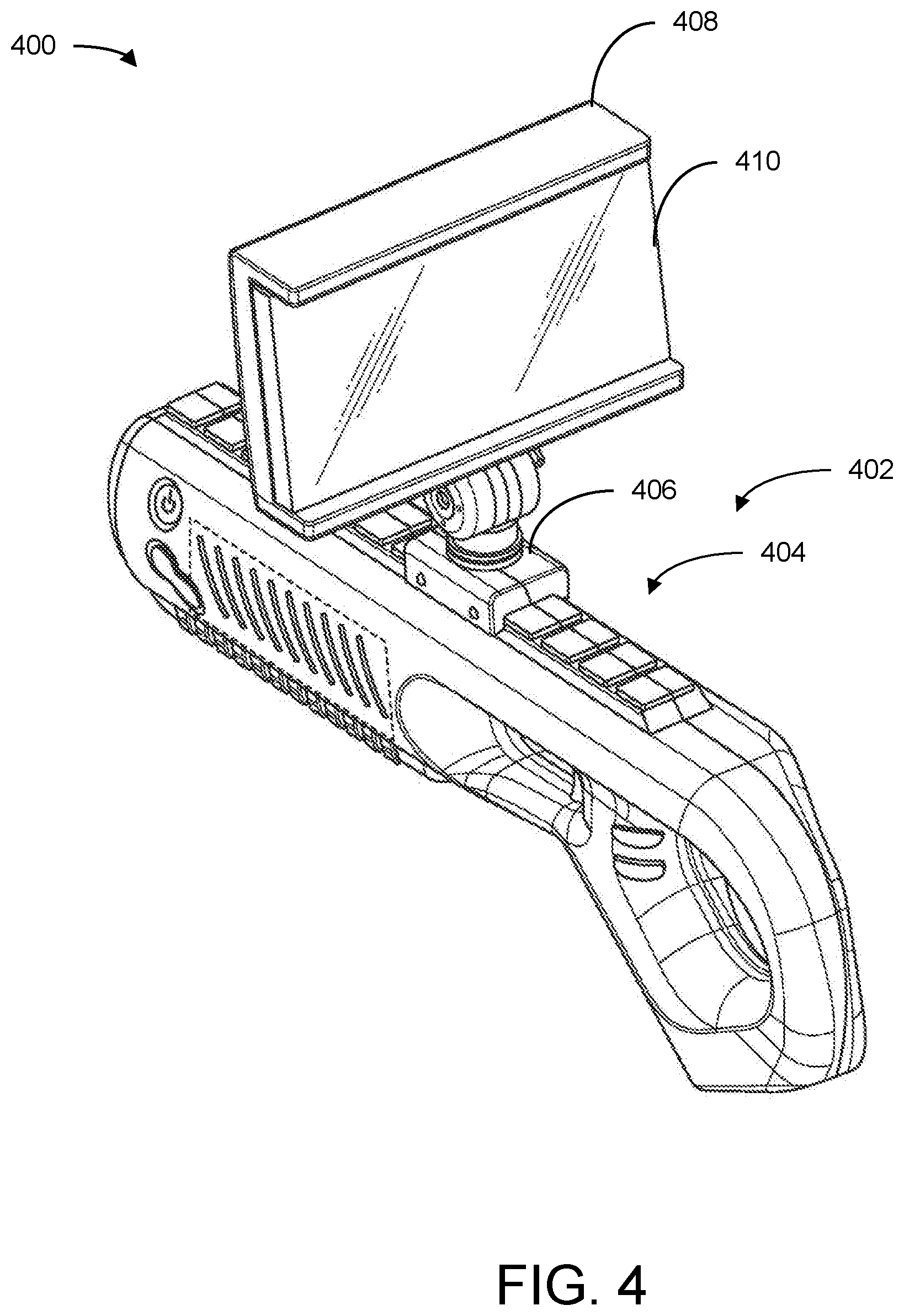
FIG. 4 is perspective view of another game console including a display device coupled to a game console housing of the game console, in accordance with some embodiments of the present disclosure.
FIG. 5 is a side view of the game console of FIG. 4, in accordance with some embodiments of the present disclosure.
FIG. 6 is a screen display of a user interface displaying various levels of difficulty for an operator to select with the game console of FIG. 3, in accordance with some embodiments of the present disclosure.
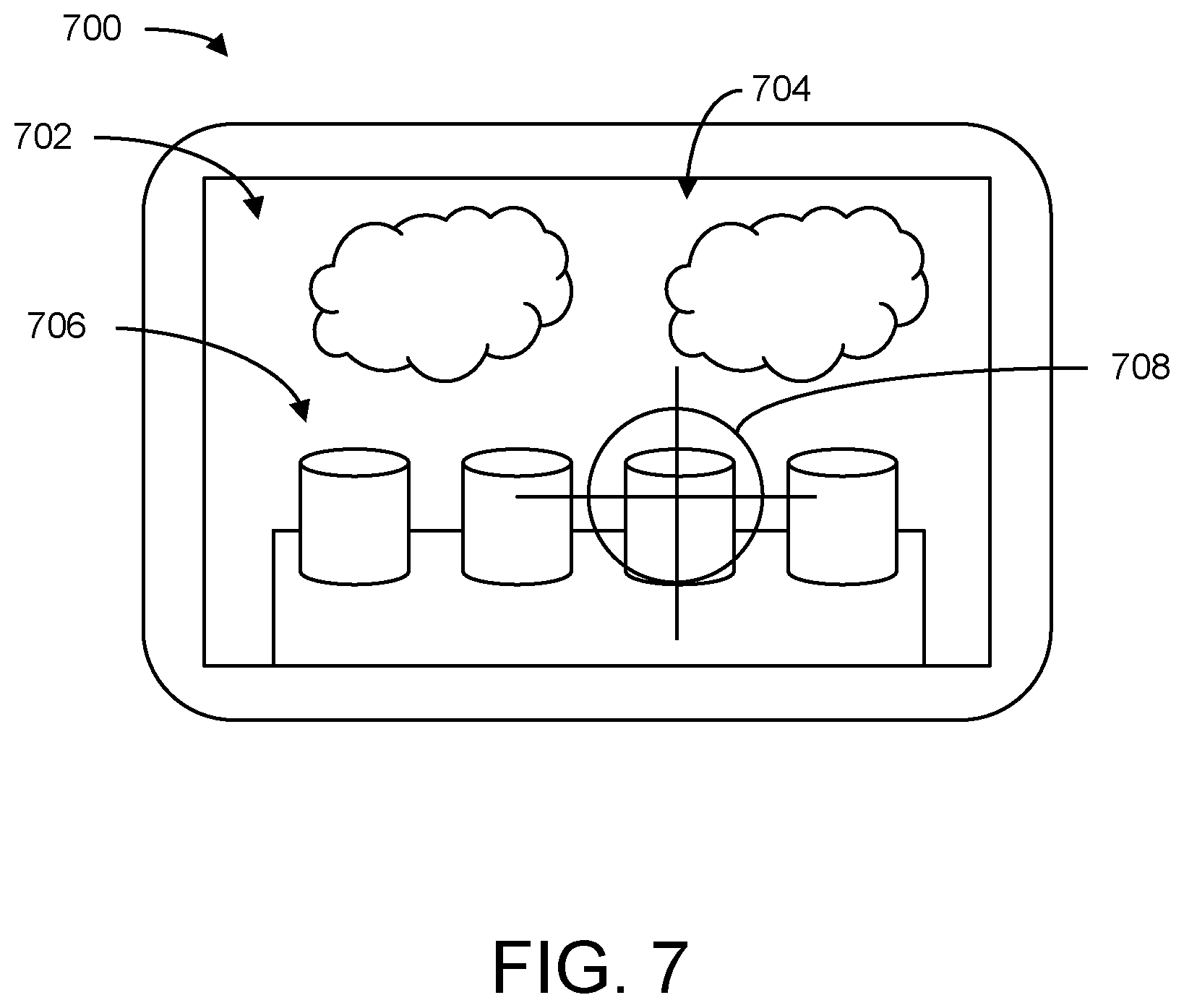
FIG. 7 is a screen display of a user interface of a game being played on the game console of FIG. 3, in accordance with some embodiments of the present disclosure.
FIG. 8 is an example flowchart outlining operation of the game console of FIG. 3, in accordance with some embodiments of the present disclosure.
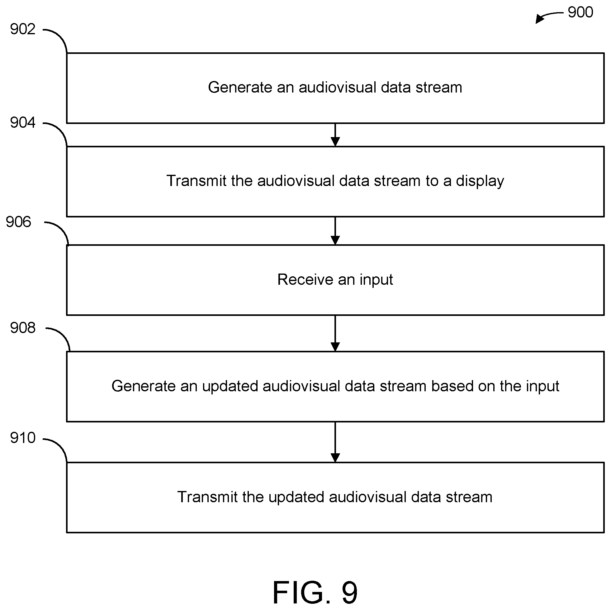
FIG. 9 is an example flowchart outlining a gaming device streaming audiovisual data to the display device of the game console of FIG. 3 while the game console provides inputs to the gaming device, in accordance with some embodiments of the present disclosure.
The foregoing and other features of the present disclosure will become apparent from the following description and appended claims, taken in conjunction with the accompanying drawings. Understanding that these drawings depict only several embodiments in accordance with the disclosure and are, therefore, not to be considered limiting of its scope, the disclosure will be described with additional specificity and detail through use of the accompanying drawings.
DETAILED DESCRIPTION
In the following detailed description, reference is made to the accompanying drawings, which form a part hereof. In the drawings, similar symbols typically identify similar components, unless context dictates otherwise. The illustrative embodiments described in the detailed description, drawings, and claims are not meant to be limiting. Other embodiments may be utilized, and other changes may be made, without departing from the spirit or scope of the subject matter presented here. It will be readily understood that the aspects of the present disclosure, as generally described herein, and illustrated in the figures, can be arranged, substituted, combined, and designed in a wide variety of different configurations, all of which are explicitly contemplated and make part of this disclosure.
The present disclosure is generally directed to a game console including a processing circuit, a game console housing, and a screen display. The processing circuit may be internally coupled to the game console housing. The screen display may be coupled to the game console housing via an external component (e.g., a screen holder). The processing circuit can communicate with the screen display to display a user interface on the screen display. The processing circuit can process various applications and/or games to display and update the user interface. The processing circuit can receive inputs from various buttons and/or detected movements of the game console housing. The processing circuit can update the user interface based on the inputs.
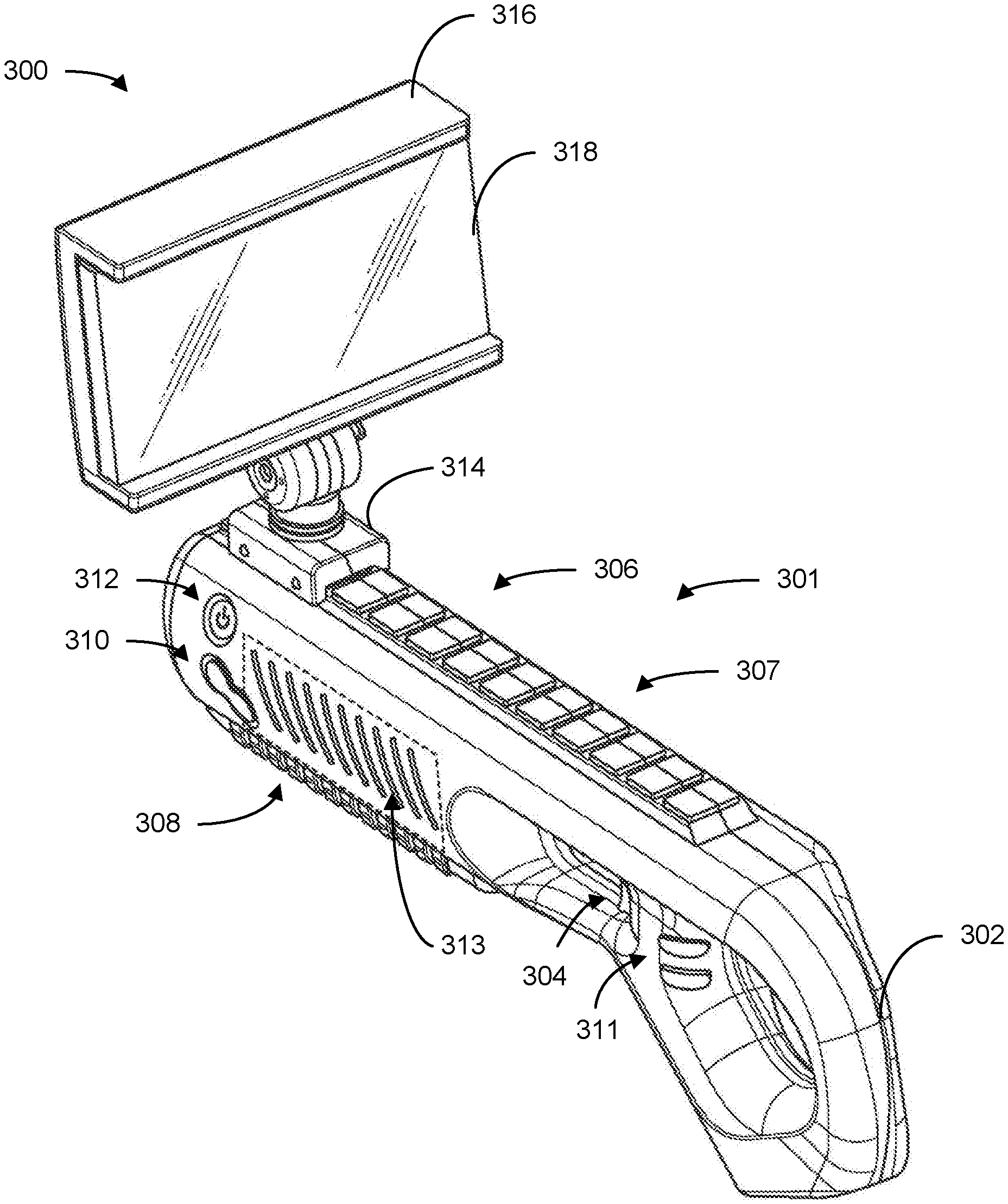
Exemplary embodiments described herein provide a game console with a game console housing that may be shaped to resemble a blaster device (e.g., a rifle, a shotgun, a machine gun, a grenade launcher, a rocket launcher, etc.). The game console housing may include a barrel, a handle, a trigger, sensors (e.g., accelerometers, gyroscopes, magnetometers, etc.), and various buttons on the exterior of the game console housing. The game console may also include a processing circuit internally coupled to the game console housing that processes applications and/or games that are associated with the game console. The game console may include a screen display that is coupled to the barrel of the game console housing. The screen display may display a user interface that is generated by the processing circuit and that is associated with the applications and/or games that the processing circuit processes. The screen display may be coupled to the game console so an operator using (e.g., playing or operating) the game console may view the user interface that is generated by the processing circuit on the screen display.
The processing circuit may receive inputs associated with the trigger, sensors, and the various buttons. The processing circuit may process the inputs to update the user interface being displayed on the screen display. The processing circuit may receive the inputs as a result of an operator using the game console and pressing one of the various buttons, maneuvering (e.g., moving) the game console so the sensors detect the movement, or pulling the trigger. The processing circuit may associate the inputs of each of the various buttons, sensors, and/or the trigger with a different action or signal to adjust the user interface on the screen display. For example, the processing circuit may identify a signal associated with an operator pulling the trigger as an indication to shoot a gun in a video game. While processing the same video game, the processing circuit may associate a signal from the various sensors indicating that the game console is being maneuvered as an indication to change the user interface from a first view to a second view. The processing circuit may process games or applications to create a virtual environment (e.g., an environment with multiple views) that operators can view by maneuvering the game console (e.g., spinning the game console around 360 degrees).
The screen display may also receive a data stream from an external device (e.g., another video game console). The external device may process an application or video game on a processing circuit of the external device to generate the data stream. The data stream may include audiovisual data. In some embodiments, the external device may transmit the data stream to the processing circuit of the game console to process and display on the screen display. An operator using the game console and/or viewing the display may press a button, pull the trigger, or maneuver the game console upon viewing the screen display. The game console may send the inputs generated by any of these interactions to the external device. The external device may process the inputs with the processing circuit of the external device and transmit an updated data stream to the game console for the screen display to display. The processing circuit of the external device may generate the updated data stream based on the inputs. Accordingly, the processing circuit of the game console may not need to perform any processing steps for the screen display to display the user interface.
Advantageously, the present disclosure describes a game console that allows an operator to be immersed in a gaming experience without an external display (e.g., a television). Because the screen display of the game console is coupled to an external component of the game console housing and can display a user interface that changes views corresponding to movement of the game console, an operator may play games on the game console while feeling that they are a part of various gaming environments. Further, the game console may interface with other game consoles to provide virtual reality functionality to games of the game consoles that would otherwise only be playable on a stationary screen. Consequently, the game console provides operators with a virtual reality experience for games and/or applications that are being processed on either an external device or the game console itself.
Another advantage to the present disclosure is the game console provides a hand held virtual reality system that does not necessarily need to be connected to a head or other body part of a user. Instead, a user may easily grab the game console and immediately be immersed in the gaming environment. Further, the user can be immersed in the gaming environment while still viewing the user's surroundings in the real world. This allows the user to avoid hitting real-world objects while playing immersive games or application in a three dimensional virtual world.
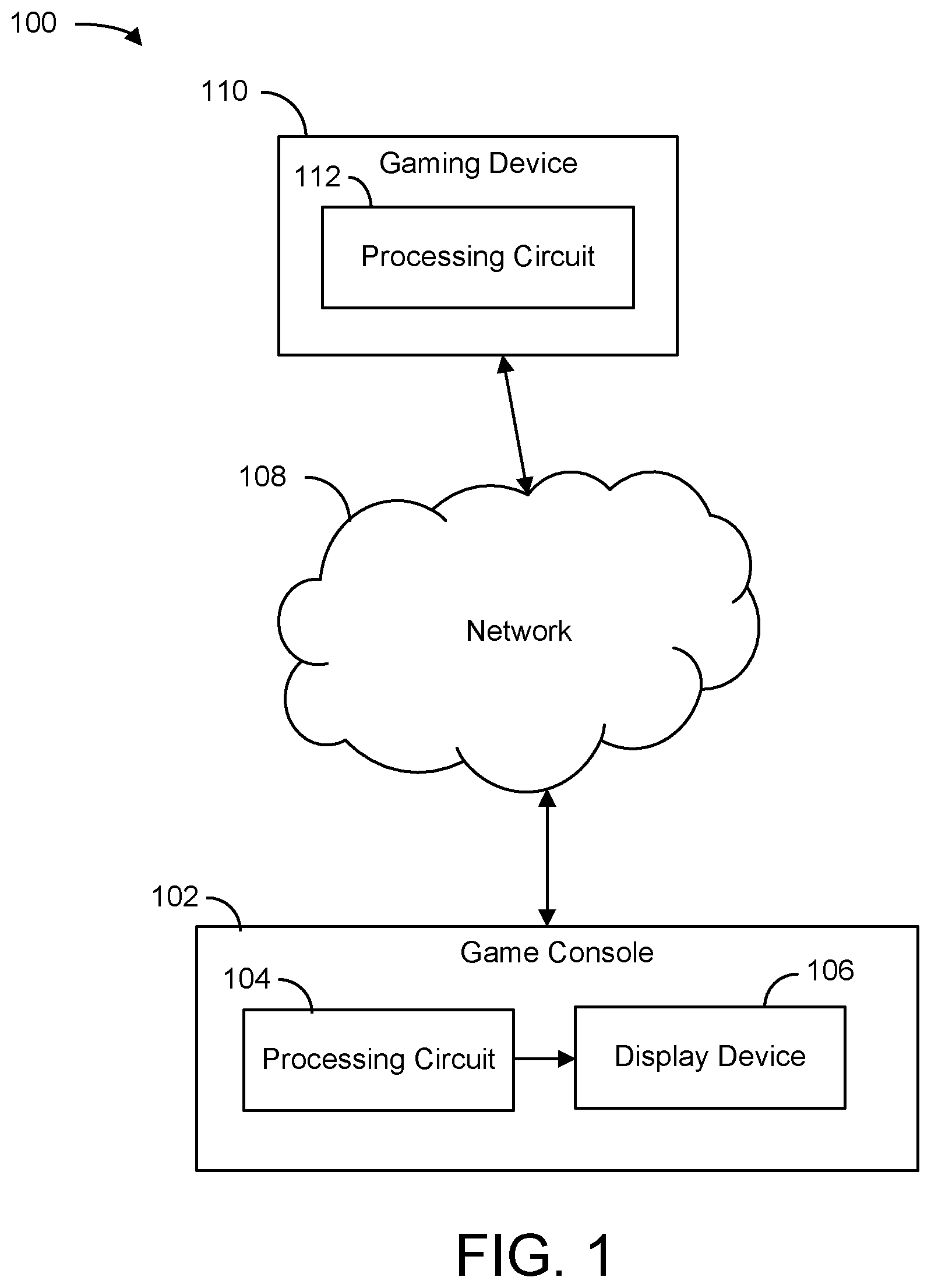
Referring now to FIG. 1, a block diagram of a gaming environment 100 is shown, in accordance with some embodiments of the present disclosure. Gaming environment 100 is shown to include a game console 102, a display device 106, a network 108, and a gaming device 110, in some embodiments. As described herein, gaming environment 100 may be a portable gaming system. Game console 102 may communicate with gaming device 110 over network 108. Display device 106 may be a part of (e.g., coupled to an exterior component of) game console 102. A processing circuit 104 of game console 102 may communicate with display device 106 to display a user interface at display device 106. Game console 102 may process and display an application or game via processing circuit 104 and display device 106, respectively. As described herein, game console 102 may be a portable gaming device. In brief overview, game console 102 may display a list of games or applications to be played or downloaded on display device 106. An operator may select a game or application from the list by moving game console 102 and pressing an input button of game console 102. Game console 102 may display the selected game or application at display device 106. The operator may control movements and actions of the game or application by maneuvering and/or pressing input buttons of game console 102. Because display device 106 is a part of game console 102, display device 106 may move with the movements of game console 102. In some embodiments, game console 102 may display movements and/or actions that are associated with applications and/or games that gaming device 110 is processing.
Network 108 may include any element or system that enables communication between game console 102 and gaming device 110 and their components therein. Network 108 may connect the components through a network interface and/or through various methods of communication, such as, but not limited to, a cellular network, Internet, Wi-Fi, telephone, Lan-connections, Bluetooth, HDMI, or any other network or device that allows devices to communicate with each other. In some instances, network 108 may include servers or processors that facilitate communications between the components of gaming environment 100.
Game console 102 may be a game console including processing circuit 104, which can process various applications and/or games. Game console 102 may include display device 106, which is coupled to an exterior component (e.g., a screen holder) of a housing of game console 102. Processing circuit 104 may display an output of the applications and/or games that game console 102 processes at display device 106 for an operator to view. Game console 102 may also include various push buttons that an operator can press to send a signal to processing circuit 104. The signal may indicate that one of the push buttons was pressed. Each push button may be associated with an action or movement of the application or game that processing circuit 104 is processing. Further, processing circuit 104 may receive inputs from sensors of game console 102 that detect various aspects of movement (e.g., velocity, position, acceleration, etc.) associated with game console 102. Processing circuit 104 may use the inputs from the sensors to affect movements and/or actions associated with the games or applications that processing circuit 104 is processing. Processing circuit 104 may generate and/or update user interfaces associated with the games and/or applications being displayed on display device 106 based on the inputs.
Display device 106 may include a screen (e.g., a display) that displays user interfaces associated with games and/or applications being processed by processing circuit 104. Display device 106 may be coupled to game console 102 via a screen holder (not shown) attached to a game console housing (also not shown) of game console 102. Display device 106 may include a screen display which displays the user interfaces. In some embodiments, display device 106 may include a touchscreen.
In some embodiments, display device 106 may display games and/or applications being processed by another device outside of game console 102 (e.g., gaming device 110). Gaming device 110 may be a device designed to process applications and/or games. Gaming device 110 is shown to include a processing circuit 112. Processing circuit 112 may process the games and/or applications and send a user interface to display device 106 to be displayed. Processing circuit 112 may receive and process signals sent from processing circuit 104. Processing circuit 112 may update the user interface being displayed at display device 106 of game console 102 based on the signals from processing circuit 104. Processing circuit 112 may communicate with processing circuit 104 over network 108 via Bluetooth. Further, processing circuit 112 may communicate with display device 106 via an HDMI connection such as a wireless HDMI connection (e.g., HDbitT.RTM., Wi-Fi, HDMI wireless, etc.) or a wired HDMI connection (e.g., HDbaseT.RTM.).
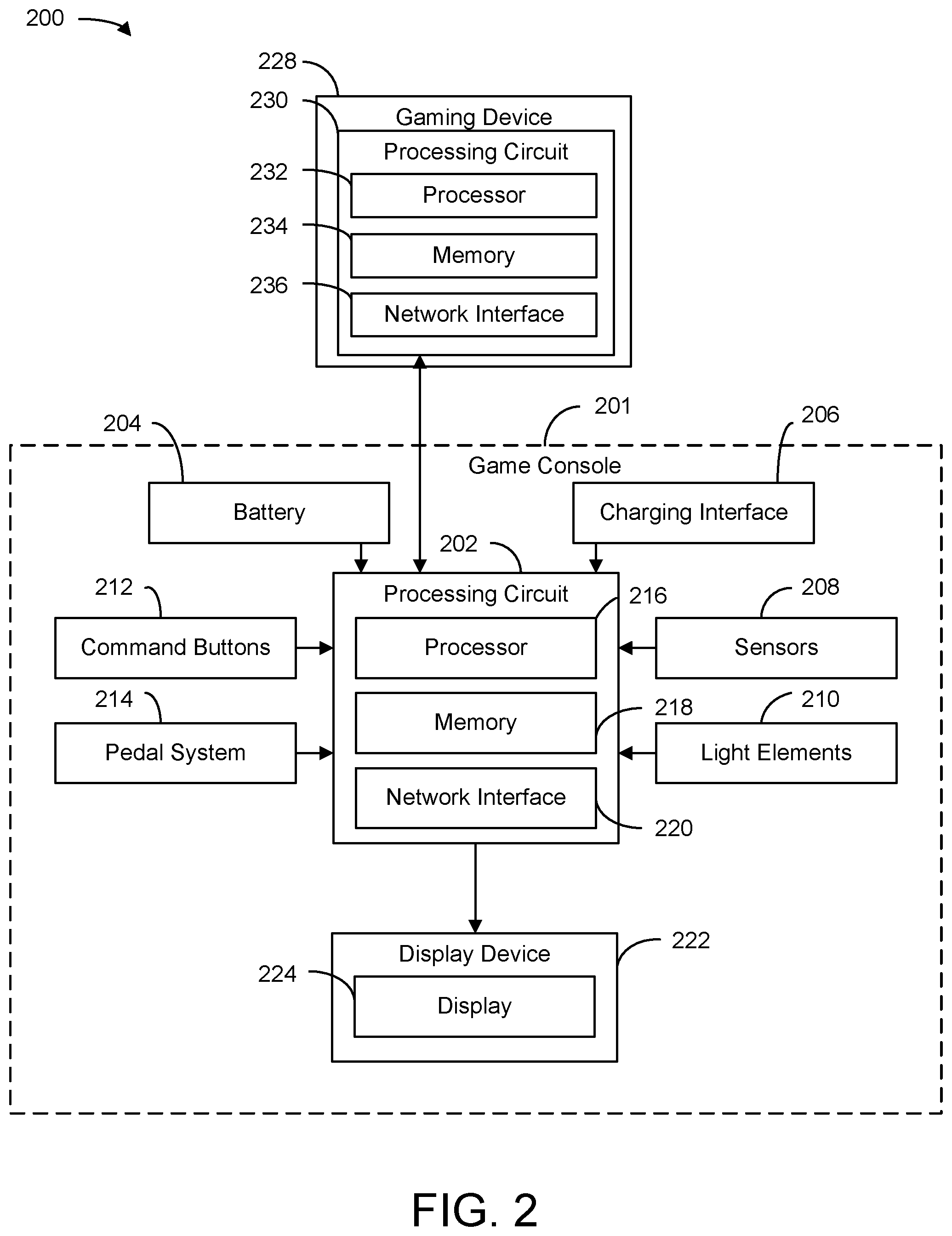
Referring now to FIG. 2, a block diagram of a gaming environment 200 is shown, in some embodiments. Gaming environment 200 may be an exemplary embodiment of gaming environment 100, shown and described with reference to FIG. 1, in some embodiments. Gaming environment 200 is shown to include a game console 201 and a gaming device 228. Game console 201 may be similar to game console 102, shown and described with reference to FIG. 1. Gaming device 228 may be similar to gaming device 110, shown and described with reference to FIG. 1. Game console 201 is shown to include a processing circuit 202, a battery 204, a charging interface 206, sensors 208, light element(s) 210, command buttons 212, a pedal system 214, and a display device 222. As described above, display device 222 may be coupled to an exterior component (e.g., via a display holder on a barrel) of game console 201. Processing circuit 202 may receive inputs from each of components 204-214, process the inputs, and display and update an output at display device 222 based on the inputs. In some embodiments, processing circuit 202 may additionally or alternatively be a part of display device 222.
Game console 201 may include a battery 204. Battery 204 may represent any power source that can provide power to game console 201. Example of power sources include, but are not limited to, lithium batteries, rechargeable batteries, wall plug-ins to a circuit, etc. Battery 204 may be charged via charging interface 206. For example, battery 204 may be a rechargeable battery. To charge battery 204, an operator may connect game console 201 to a wall outlet via charging interface 206. Once game console 201 has finished charging, the operator may disconnect game console 201 from the wall outlet and operate game console 201 with the power stored in the rechargeable battery. The operator may disconnect game console 201 from the wall outlet at any time to operate game console 201. In some cases, the operator may operate game console 201 while it is connected to the wall outlet. Battery 204 may provide power to processing circuit 202 so processing circuit 202 may operate to process applications and/or games.
As shown in FIG. 2, processing circuit 202 includes a processor 216, memory 218, and a communication device (e.g., a receiver, a transmitter, a transceiver, etc.), shown as network interface 220, in some embodiments. Processing circuit 202 may be implemented as a general-purpose processor, an application specific integrated circuit ("ASIC"), one or more field programmable gate arrays ("FPGAs"), a digital-signal-processor ("DSP"), circuits containing one or more processing components, circuitry for supporting a microprocessor, a group of processing components, or other suitable electronic processing components. Processor 216 may include an ASIC, one or more FPGAs, a DSP, circuits containing one or more processing components, circuitry for supporting a microprocessor, a group of processing components, or other suitable electronic processing components. In some embodiments, processor 216 may execute computer code stored in the memory 218 to facilitate the activities described herein. Memory 218 may be any volatile or non-volatile computer-readable storage medium capable of storing data or computer code relating to the activities. According to an exemplary embodiment, memory 218 may include computer code modules (e.g., executable code, object code, source code, script code, machine code, etc.) for execution by processor 216.
In some embodiments, processing circuit 202 may selectively engage, selectively disengage, control, and/or otherwise communicate with the other components of game console 201. As shown in FIG. 2, network interface 220 may couple processing circuit 202 to display device 222 and/or an external device (e.g., gaming device 110). In other embodiments, processing circuit 202 may be coupled to more or fewer components. For example, processing circuit 202 may send and/or receive signals from the components of game console 201 such as light elements 210; charging interface 206; battery 204; command buttons 212 (e.g., a power button, input buttons, a trigger, etc.); one or more sensors, shown as sensors 208; and/or pedal system 214 (e.g., position detectors indicating a position of pedals of pedal system 214) via network interface 220.
Processing circuit 202 may send signals to display device 222 to display a user interface on a display 224 of display device 222 via network interface 220. Network interface 220 may utilize various wired communication protocols and/or short-range wireless communication protocols (e.g., Bluetooth, near field communication ("NFC"), HDMI, RFID, ZigBee, Wi-Fi, etc.) to facilitate communication with the various components of game console 201, including display device 222, and/or gaming device 228. In some embodiments, processing circuit 202 may be internally coupled to display device 222 via a tethered HDMI cable located inside a housing of game console 201 that runs between processing circuit 202 and display device 222. In some embodiments, processing circuit 202 may be connected to display device 222 via HDbitT.RTM., which is described below. In some embodiments, processing circuit 202 may be connected to display device 222 via an HDMI low latency wireless transmission technology. Advantageously, by using an HDMI low latency wireless transmission technology, display device 222 may connect to both external devices and to processing circuit 202.
According to an exemplary embodiment, processing circuit 202 may receive inputs from various command buttons 212 and/or pedal system 214 that are located on an exterior surface of game console 201. Examples of command buttons 212 include, but are not limited to, a power button, input buttons, a trigger, etc. Pedal system 214 may include multiple pedals (input buttons) that are coupled to each other so only one pedal may be pressed at a time. In some embodiments, the pedals may be pressed to varying degrees. Processing circuit 202 may receive an input when an operator may press on a pedal of pedal system 214 and identify how much the operator pressed on the pedal based on data detected by sensors coupled to the pedal. Processing circuit 202 may receive the inputs and interpret and implement them to perform an action associated with a game or application that processing circuit 202 is currently processing.
Processing circuit 202 may change a display (e.g., a user interface) of display 224 based on the inputs. The inputs from the input buttons, the trigger, and/or the pedal system may be an indication that the operator of game console 201 desires that their character in a game jumps, crouches, dives/slides, throws a knife, throws a grenade, switches weapons, shoots a weapon, moves backward, moves forward, walks, jogs, runs, sprints, etc. The inputs from the input buttons, the trigger, and/or the pedal system may additionally or alternatively be an indication that the operator of game console 201 desires to perform various different actions while in menus of the game such as scroll up, scroll down, and/or make a menu selection (e.g., select a map, select a character, select a weapon or weapons package, select a game type, etc.). In this way, an operator may utilize game console 201 as a mouse or roller ball that can move a cursor on display 224 to select an option that display 224 displays. Inputs from the power button may be an indication that the operator of game console 201 desires that game console 201 be turned on or off.
In some embodiments, an operator may calibrate game console 201 to adjust a rate of change of views of display 224 versus movement that sensors 208 detects. For example, game console 201 may be configured to change views of display 224 at a same rate that an operator moves game console 201. The operator may wish for the views to change at a slower rate. Accordingly, the operator may adjust the settings of game console 201 so display 224 changes views slower than the operator moves game console 201.
In some embodiments, an operator may calibrate game console 201 based on the actions being performed on a user interface. For example, an operator may calibrate game console 201 so the user interface changes at the same rate that the operator moves game console 201 when playing a game. Within the same configuration, the operator may also calibrate game console 201 so the operator can maneuver a cursor at a faster rate than the operator moves game console 201 when selecting from a drop down menu or from other types of menus or option interfaces.
In some embodiments, processing circuit 202 may receive an indication regarding a characteristic within a game (e.g., a health status of a character of the game) operated by game console 201 and control light elements 210 of a light bar (not shown) to provide a visual indication of the characteristic within the game operated by game console 201. For example, processing circuit 202 may receive an indication regarding a health status of a character within the game that is associated with the operator of game console 201 and control light elements 210 (e.g., selectively illuminate one or more of light elements 210, etc.) to provide a visual indication of the character's health via the light bar. By way of another example, processing circuit 202 may receive an indication regarding a number of lives remaining for a character within the game that is associated with the operator of game console 201 and control light elements 210 (e.g., selectively illuminate one or more of light elements 210, etc.) to provide a visual indication of the number of remaining lives via the light bar. In another example, processing circuit 202 may receive an indication regarding a hazard or event within the game (e.g., radiation, warning, danger, boss level, level up, etc.) and control light elements 210 to change to a designated color (e.g., green, red, blue, etc.) or to flash to provide a visual indication of the type of hazard or event within the game via the light bar.
In some embodiments, processing circuit 202 may receive inputs from sensors 208 of game console 201. Sensors 208 may include an accelerometer, a gyroscope, and/or other suitable motion sensors or position sensors that detect the spatial orientation and/or movement of game console 201 (e.g., a magnetometer). The accelerometer and gyroscope may be a component of an inertial measurement unit (not shown). The inertial measurement unit may include any number of accelerometers, gyroscopes, and/or magnetometers to detect the spatial orientation and/or movement of game console 201. The inertial measurement unit (IMU) may detect the spatial orientation and/or movement of game console 201 by detecting the spatial orientation and/or movement of a game console housing (not shown) of game console 201. The IMU may transmit data identifying the spatial orientation and/or movement of game console 201 to processing circuit 202. Based on signals received from sensors 208, processing circuit 202 may adjust the display provided by display 224 of display device 222. For example, sensors 208 may detect when game console 201 is pointed up, pointed down, turned to the left, turned to the right, etc. Processing circuit 202 may adaptively adjust the display on display 224 to correspond with the movement of game console 201.
In some embodiments, game console 201 may include speakers (not shown). Processing circuit 202 may transmit audio signals to the speakers corresponding to inputs that processing circuit 202 processes while processing a game and/or application. The audio signals may be associated with the game or application. For example, an operator may be playing a shooting game that processing circuit 202 processes. The operator may pull the trigger of game console 201 to fire a gun of the shooting game. Processing circuit 202 may transmit a signal to the speakers to emit a sound associated with a gun firing.
In some embodiments, game console 201 may be used as a mouse and/or keyboard to interact with various dropdown menus and selection lists being displayed via display device 222. In some cases, the various dropdown menus and selection lists may be related to an online exchange that allows operators to select a game or application to download into memory 218 of processing circuit 202. The operators may select the game or application by reorienting game console 201 to move a cursor that display device 222 is displaying on a user interface including dropdown menus and/or selection lists. Sensors 208 of game console 201 may detect the movements of game console 201 and send signals to processing circuit 202 that are indicative of the movements including at least movement direction and/or speed. Processing circuit 202 may receive and process the signals to determine how to move the cursor that display device 222 is displaying. Processing circuit 202 may move the cursor corresponding to the movement of the game console 201. For example, in some instances, if an operator points game console 201 upward, processing circuit 202 may move the cursor upwards. If an operator points game console 201 downward, processing circuit 202 may move the cursor downwards. The operator may configure game console 201 to invert the movements or change the movements in any manner to affect the movement of the cursor. In some embodiments, processing circuit 202 may receive inputs that correspond to the movement and the speed of the movement of game console 201 based on the movement of an end of the barrel of game console 201.
In some embodiments, game console 201 may include a calibrated floor position that movements of game console 201 may be detected against. An administrator may calibrate the floor position by setting a base position of the gyroscopes of game console 201 that are associated with a pitch of game console 201. The pitch of game console 201 may be determined based on the position of game console 201 relative to the calibrated floor position. For example, an administrator may calibrate a floor position of game console 201 to be when game console 201 is positioned parallel with the ground. The administrator may position and/or determine when game console 201 is parallel with the ground and set the gyroscope readings associated with the pitch of the position as a calibrated floor position. If the gyroscopes detect that game console 201 is pointing at a position above the calibrated floor position, the gyroscopes may send data indicating the position of game console 201 as pointing up and/or a degree of how far up console 201 is pointing relative to the calibrated floor position to processing circuit 202.
In some embodiments, the gyroscopes may send position data to processing circuit 202 and processing circuit 202 may determine the position of game console 201 compared to the calibrated floor position. Consequently, processing circuit 202 may determine a pitch position of game console 201 relative to a consistent fixed pitch position instead of relative to a starting pitch position of game console 201 upon start-up of a game or application. Advantageously, an administrator may only set a calibrated floor position for the pitch of game console 201. Processing circuit 202 may determine and set a calibrated yaw position of game console 201 upon boot up or upon starting processing of a game or application. A user playing the game or application may adjust the calibrated floor position and/or calibrated yaw position by accessing the settings associated with the game, application, or game console 201.
The gyroscopic data may include pitch, yaw, and/or roll of game console 201. The pitch may correspond to the barrel of game console 201 moving up or down and/or a position on a y-axis (e.g., a y-axis tilt of game console 201). The yaw may correspond to the barrel of game console 201 moving side-to-side and/or a position on an x-axis (e.g., an x-axis tilt of game console 201). The roll may correspond to the barrel rotating clockwise or counterclockwise around a z-axis. The y-axis may point from the ground to the sky, the x-axis may be perpendicular to the y-axis, and the z-axis may be an axis extending from an end (e.g., the barrel or the handle) of game console 201. Gyroscopes of the IMU may be positioned to detect the pitch, yaw, and/or roll of game console 201 as gyroscopic data along with a direction of each of these components. The gyroscopes may transmit the gyroscopic data to processing circuit 202 to indicate how game console 201 is moving and/or rotating.
Processing circuit 202 may move a cursor on a user interface by analyzing gyroscopic data that gyroscopes of game console 201 send to processing circuit 202 along with other positional data (e.g., acceleration data from accelerometers). Processing circuit 202 may process the gyroscopic data to convert it into mouse data. Based on the mouse data, processing circuit 202 can move a cursor on the user interface accordingly. For example, if a detected pitch indicates game console 201 is pointing up, processing circuit 202 may move a cursor up. If a detected yaw indicates game console 201 is pointing left, processing circuit 202 may move the cursor left. Consequently, the combination of processing circuit 202 and the gyroscopes can act as an HID compliant mouse that can detect a movement of game console 201 and move a cursor of a user interface corresponding to the movement. Further, processing circuit 202 may send such gyroscopic data to another device (e.g., gaming device 228) for similar processing. Advantageously, by acting as an HID compliant mouse, game console 201 can move cursors associated with various games and application according to a set standard. Game and application manufacturers may not need to create their games or applications to specifically operate on processing circuit 202.
Processing circuit 202 may also use gyroscopic data (in combination with other data such as data from one or more accelerometers) of game console 201 to act as an HID compliant joystick. When processing a game with a user interface emulating a view of a person in a three dimensional environment, processing circuit 202 may receive gyroscopic data associated with the pitch, yaw, and/or roll of game console 201 compared to a calibrated floor position as described above. Processing circuit 202 may convert the gyroscopic data and accelerometer data to HID compliant joystick data associated with a direction and acceleration of movement of game console 201. Based on the direction and acceleration, processing circuit 202 may update the user interface.
For example, processing circuit 202 may process a three dimensional environment of a game or application. Processing circuit 202 may receive gyroscopic data indicating that game console 201 is pointing up relative to a calibrated pitch position and convert the data to HID compliant joystick data. Based on the HID compliant joystick data, processing circuit 202 may update the user interface to cause a character of the game or application to look up in the three dimensional environment (e.g., reorient the screen to look up in the three dimensional environment). Processing circuit 202 may also receive gyroscopic data indicating a roll of game console 201. A roll may correspond to an action in a game or application. For example, an operator may roll game console 201 to peak around a corner in a game.
Various positions of game console 201 may correspond to actions in a game. For example, gyroscopic data may indicate that game console 201 is pointing down. Such a movement may be associated with reloading in a game. Processing circuit 202 may receive this data, convert the data to HID compliant joystick data, and update the user interface so a reload animation is performed. Game console 201 may associate various motion gestures with various actions depending on the game or application that game console 201 is processing.
In some embodiments, display device 222 may operate as a digital keyboard. Display device 222 may present a digital keyboard at display 224 and an operator may interact with the digital keyboard to select various keys. The operator may select various keys by moving a cursor as discussed above and pressing a button or pulling the trigger of game console 201. In some embodiments, display device 222 may include a touchscreen. In these embodiments, an operator may physically touch an electronic representation of each key on display 224 of display device 222 to select keys of the digital keyboard.
In some embodiments, game console 201 may generate a virtual environment for an operator to view. Game console 201 may generate the virtual environment based on a game or application that processing circuit 202 processes. Processing circuit 202 may generate the virtual environment by processing software associated with the game or application. The virtual environment may be a three dimensional environment that an operator can interact with by providing various inputs into game console 201. A portion of the virtual environment may be displayed by display device 222. An operator that is operating game console 201 may change the portion of the virtual environment being displayed by display device 222 by providing an input into game console 201. Processing circuit 202 may receive the input and update the display of display device 222 based on the input. In some embodiments, processing circuit 202 can continue to generate and update views of the virtual environment that are not currently being displayed by display device 222. Advantageously, by continuing to generate and update portions of the environment that are not currently being shown by display device 222, if the operator provides an input to cause the display to change to another view of the environment, processing circuit 202 may not need to generate a new view responsive to the input. Instead, processing circuit 202 can display a view that processing circuit 202 has already generated. Consequently, processing circuit 202 may process the virtual environment faster after initially generating the virtual environment.
For example, an operator may be playing a war game simulator on game console 201. Processing circuit 202 of game console 201 may generate a three dimensional battlefield associated with the war game. The three dimensional battlefield may include terrain (e.g., bunkers, hills, tunnels, etc.) and various characters that interact with each other on the battlefield. The operator playing the war game can view a portion of the battlefield through display device 222. The portion of the battlefield may be representative of what a person would see if the battlefield was real and the person was on the battlefield. The operator may change views (e.g., change from a first view to a second view) of the battlefield by reorienting game console 201. For instance, if the operator spins 360 degrees, processing circuit 202 could display a 360 degree view of the battlefield on display device 222 as the operator spins. If the operator pulls the trigger of game console 201, a sequence associated with firing a gun may be displayed at display device 222. Further, if the operator presses on a pedal of pedal system 214, a character representation of the operator may move forward or backwards in the battlefield corresponding to the pedal that was pressed. Other examples of interactions may include the operator pressing an input button to select an item (e.g., a medical pack) on the battlefield, the operator pressing a second input button to reload, the operator pressing a third input button to bring up an inventory screen, etc. As described, by pressing an input button, the operator may change the state of the input button from an unpressed state to a pressed state. Similarly, by pulling the trigger, an operator may change the state of the trigger from an unpulled state to a pulled state. Further, a detected change in position of game console 201 may be described as a change in state of the position of game console 201.
Various buttons (e.g., command buttons 212) may map to different actions or interactions of games that processing circuit 202 processes. Different games may be associated with different button mappings. Further, the mappings may be customizable so an operator can control actions that each button is associated with. For example, a button in one game may be associated with a "jump" movement in the game. In another game, the same button may be associated with a "sprint" movement while another button of the various buttons may associated with the jump movement.
In some embodiments, the various buttons may each be associated with a letter or button on a keyboard displayed on a user interface. An operator may customize the buttons to be associated with different letters based on the operator's preferences. A keyboard may be displayed on display 224 and the operator may select keys of the keyboard using the various push buttons.
In some embodiments, game console 201 may operate as an input and display device for an external gaming device (e.g., gaming device 228). For example, gaming device 228 of gaming environment 200 may be in communication with processing circuit 202 of game console 201. Gaming device 228 may include a processing circuit 230 having a processor 232, memory 234, and a network interface 236. Processing circuit 230, processor 232, memory 234, and network interface 236 may be similar to processing circuit 202, processor 216, memory 218, and network interface 220 of game console 201, respectively. In some cases, gaming device 228 may include a plug-in that facilitates transmission of an HDMI output (e.g., an audiovisual data stream generated by processing circuit 230) to display device 222 or to processing circuit 202 to forward to display device 222. In some cases, gaming device 228 may transmit audio data that corresponds to visual data that gaming device 228 transmits. Consequently, gaming device 228 may transmit audiovisual data streams to game console 201 to display at display device 222.
In some embodiments, processing circuit 202 of game console 201 may be or may include a Bluetooth processor including various Bluetooth chipsets. The Bluetooth processor may receive inputs from various components of game console 201, and send the inputs to processing circuit 230 for processing. Advantageously, Bluetooth processors may be physically smaller and require less processing power and/or memory than other processors because the Bluetooth processors may not need to process applications or games or produce an audiovisual data stream to display at display device 222. Instead, the Bluetooth processor may only receive and package inputs based on operator interactions with game console 201 and transmit the inputs to gaming device 228 for processing. In addition to Bluetooth, other wireless protocols may utilized to transmit inputs to gaming device 228. For example, processing circuit 202 may transmit the inputs to gaming device 228 through infrared signals. The inputs may be transmitted through any type of wireless transmission technology.
In some embodiments, gaming device 228 may transmit an HDMI output to display device 222 using HDbitT.RTM. technology. HDbitT.RTM. may enable transmission of 4K Ultra HD video, audio, Ethernet, power over Ethernet, various controls (e.g., RS232, IR, etc.) and various other digital signals over wired and/or wireless communication mediums. For example, HDbitT.RTM. may enable data transmission via UTP/STP Cat5/6/7, optical fiber cables, power lines, coaxial cables, and/or wireless transmission. Gaming device 228 may receive inputs from game console 201 (e.g., via Bluetooth), process the inputs based on a game or application that gaming device 228 is currently processing, and transmit an updated HDMI output (e.g., an updated audiovisual datastream) to display device 222 using HDbitT.RTM. technology. Advantageously, by using HDbitT.RTM. to transmit data streams, gaming device 228 may wirelessly transmit high definition audiovisual data signals to display device 222 for users that are using game console 201 to view. HDbitT.RTM. may allow for gaming device 228 to transmit high definition audiovisual data signals over large distances so users can use game console 201 far away from gaming device 228 (e.g., 200 meters) or between rooms in a house. For example, operators may use game console 201 in various rooms of a house without moving gaming device 228 between the rooms.
Gaming device 228 may process games and/or applications. Gaming device 228 may generate a user interface associated with the games or applications and send the user interface to processing circuit 202 or directly to display device 222. If gaming device 228 sends the user interface to display device 222, display device 222 may display the user interface at display 224 and play any audio that gaming device 228 sent to display device 222 via an audio component (e.g., one or more speakers) of game console 201. In some embodiments, a speaker of gaming device 228 may play the audio via speakers connected to gaming device 228 (e.g., speakers on a television connected to gaming device 228).
In some instances, an operator operating game console 201 may view the user interface that gaming device 228 generated and sent to display device 222. The operator may interact with the user interface by pressing input buttons (e.g., command buttons 212, pedal system 214, a trigger, etc.) of game console 201 or reorienting game console 201. Processing circuit 202 can receive the input signals generated from either action and transmit (e.g., forward) the inputs to processing circuit 230 of gaming device 228. Processing circuit 202 may transmit the input signals to processing circuit 230 via Bluetooth, as described above. Gaming device 228 may receive and process the input signals. Gaming device 228 can consequently provide an updated user interface (e.g., an updated data stream that adjusts the user interface currently being displayed at display device 222) to game console 201 (e.g., via HDbitT.RTM.). Gaming device 228 may either send the updated user interface directly to display device 222 to update the display of display 224 or to processing circuit 202 for processing circuit 202 to update the display. Advantageously, as described, game console 201 can connect to gaming device 228 to display games and/or applications designed for gaming device 228. Game console 201 can display the game or application on display device 222. An operator accessing game console 201 may play the games or applications by providing inputs via game console 201. Processing circuit 230 of gaming device 228 may perform the processing functions of the games or applications so processing circuit 202 of game console 201 may not need to perform such functions or have the capability (e.g., processing power and/or memory requirements) to do so.
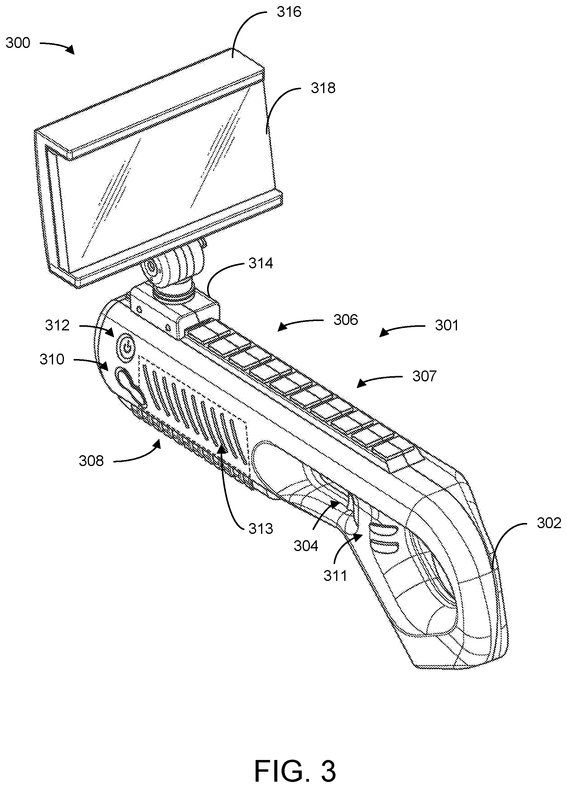
Referring now to FIG. 3, a perspective view of a game console 300 including a display device 316 coupled to a game console housing 301 via a screen holder 314 is shown, in accordance with some embodiments of the present disclosure. Game console 300 may be similar to and include similar components to game console 201, shown and described with reference to FIG. 2. Display device 316 may be similar to display device 222, shown and described with reference to FIG. 2. Game console housing 301 is shown to include a handle 302, a trigger 304, a barrel 306, latches 307, a grip 308, command buttons 310 and 311, a power button 312, and light elements 313. Game console housing 301 may be shaped to resemble a blaster device (e.g., a rifle, a shotgun, a machine gun, a grenade launcher, a rocket launcher, etc.). Barrel 306 may be shaped to resemble a barrel of such a blaster device (e.g., barrel 306 may be shaped like a tube and extend away from handle 302 and trigger 304). Screen holder 314 may be coupled to barrel 306 such that an operator holding game console 300 may view display device 316, which is attached to screen holder 314, when the operator is holding game console 300. Screen holder 314 may be coupled to a top of barrel 306. It should be understood that the positions and number of handles, triggers, barrels, latches, grips, command buttons, and light elements as shown and described with reference to FIG. 3 are meant to be exemplary. Game console housing 301 may include any number of handles, triggers, barrels, latches, grips, command buttons, and light elements and they can be in any position and in any size or orientation on game console housing 301. Further, screen holder 314 and display device 316 may be any shape or size and coupled to any component of game console housing 301 and are not meant to be limited by this disclosure.
Game console 300 may also include a processing circuit (e.g., processing circuit 202) (not shown). The processing circuit may be internally coupled to game console housing 301. In some embodiments, the processing circuit may be insulated by protective components (e.g., components that prevent the processing circuit from moving relative to game console housing 301 or from being contacted by other components of game console 300) so the processing circuit may continue operating while operators are moving game console 300 to play a game and/or application. Further, in some embodiments, the processing circuit may be coupled to display device 316. The processing circuit may be coupled to display device 316 via any communication interface such as, but not limited to, an HDMI cable, an HDMI low latency wireless transmission technology, HDbitT.RTM., etc. The processing circuit may generate and update a user interface being shown on display device 316 based on a game or application that the processing circuit is processing and/or inputs that the processing circuit processes, as described above with reference to FIG. 2.
Display device 316 may be removably coupled to game console housing 301 via latches 307 and screen holder 314. Display device 316 may be coupled to screen holder 314. Latches 307 may include multiple latches that are elevated so a screen holder (e.g., screen holder 314) may be attached to any of the latches. An operator operating game console 300 may remove screen holder 314 from any of the latches and reattach screen holder 314 to a different latch to adjust a position of screen holder 314 and consequently a position of display device 316. In some embodiments, latches 307 and screen holder 314 may be configured so an operator may slide screen holder 314 between latches and lock screen holder 314 into place to set a position of screen holder 314. In some embodiments, screen holder 314 and/or display device 316 may be a part of game console housing 301.
Display device 316 may be coupled to screen holder 314. Display device 316 may be coupled to screen holder 314 with a fastener such as a snap fit, magnets, screws, nails, loop and hooks, etc. In some embodiments, display device 316 and screen holder 314 may be the same component. In these embodiments, display device 316 may be coupled to a latch of latches 307. In some embodiments, display device 316 may be rotatably coupled to screen holder 314 so display device 316 can be rotated about screen holder 314 to a position that an operator desires.
Display device 316 may be a displaying device that can communicate with the processing circuit of game console 300 to display a user interface of a game or application being processed by the processing circuit. In some embodiments, display device 316 may include an internal processing circuit including at least a processor and memory (not shown) that facilitates the transmission of data between display device 316 and the processing circuit of game console 300 and/or a processing circuit of an external device. Display device 316 is shown to include display 318. Display 318 may be similar to display 224, shown and described with reference to FIG. 2. Display device 316 may receive a data stream including a user interface from the processing circuit of game console 300 and display the user interface at display 318.
An operator may press command buttons 310 or 311 and/or power button 312 and/or pull trigger 304 to provide an input to the processing circuit of game console 300. By providing an input to the processing circuit, the operator may adjust the user interface that the processing circuit of game console 300 is providing via display device 316. For example, an operator may perform an action in a game by pressing one of command buttons 310 or 311. In another example, an operator may turn game console 300 on or off by pressing power button 312. Further, the operator may move (e.g., reorient) game console 300 to provide an input to the processing circuit and adjust the user interface of display device 316, as described above.
In some embodiments, game console 300 may include sensors (e.g., sensors) that are internally coupled to game console housing 301. The sensors may be a part of an inertial measurement unit that includes sensors such as, but not limited to accelerometers, gyroscopes, magnetometers, etc. The sensors may provide position data identifying a position of game console housing 301 to the processing circuit of game console 300. The processing circuit may receive the position data and update a user interface of display 318 based on the position data.
To update the user interface, the processing circuit may receive current position data and compare the current position data to previous position data corresponding to a previous position of the game console housing. The processing circuit may identify a difference between the position data and update the user interface based on the difference. For example, the processing circuit may receive current position data of game console housing 301. Previous position data may indicate that game console housing 301 was pointing straight. The processing circuit may compare the current position data with the previous position data and determine that game console housing 301 is pointing left compared to the position of the previous position data. Consequently, the processing circuit may change a view of the user interface display 318 to move to the left of a virtual environment or move a cursor on the user interface left. In some embodiments, the previous position data may be a calibrated position of game console housing 301 set by an operator.
Characteristics of games or applications being processed by the processing circuit of game console 201 may be shown via light elements 313. Light elements 313 may include slits in game console housing 301 with light bulbs that can provide different colors of light. The processing circuit of game console 300 may communicate with light elements 313 to provide light based on the game or application that the processing circuit is currently processing. Light elements 313 may provide light based on characteristics of the game or application that the processing circuit is processing. For example, light elements 313 may indicate an amount of health a character of a game has left based on the number of light elements 313 that are lit. In another example, light elements 313 may provide a number of lives that a character has left by lighting up a number of light elements 313 that corresponds to the number of lives the character has left. Light elements 313 may display any sort of characteristics of games or applications.
In an exemplary embodiment, an operator operating game console 300 may hold game console 300 with one or two hands. In some instances, an operator may hold game console 300 with one hand grabbing handle 302 and another hand holding onto a portion of game console housing 301 with a finger on trigger 304. In other instances, the operator may use one hand to pull trigger 304 while another hand grabs grip 308. Grip 308 may include a substance that an operator can grip without sliding a hand along barrel 306 (e.g., rubber). In some embodiments, portions of grip 308 may be elevated from other portions of grip 308 to provide operators with further protections from sliding their hands. Grip 308 may be positioned on barrel 306 so hands that grab grip 308 can also push any of command buttons 310 and/or power button 312 without adjusting their position. While holding game console 300, the operator may view display device 316.
Referring now to FIG. 4, a perspective view of a game console 400 including a display device 408 coupled to a game console housing 402 via a screen holder 406 is shown, in accordance with some embodiments of the present disclosure. Game console 400 may be similar to game console 300, shown and described with reference to FIG. 3. Game console 400 is shown to include a game console housing 402, latches 404, a screen holder 406, and a display device 408. Display device 408 is shown to include a display 410. Each of components 402-410 may be similar to corresponding components of game console 300. However, screen holder 406 of game console 400 may be coupled to a latch of latches 404 that is different from the latch that screen holder 314 of game console 300 is coupled to. Screen holder 406 may be coupled to a latch that is closer to an operator of game console 400 so the operator may more easily view display 410 when playing games or applications of game console 400. Screen holder 406 may be adjustable to be position at different locations on a barrel (e.g., on a latch of latches 404) of game console housing 402. Advantageously, screen holder 406 may be coupled to any latch of latches 404 so an operator may operate game console 400 with display 410 at any distance from the operator.
Referring now to FIG. 5, a side view of game console 400, shown and described with reference to FIG. 4, is shown, in accordance with some embodiments of the present disclosure. Game console 400 is shown to include a handle 501, a trigger 502, a grip 504, command buttons 506, a pedal 508, screen holder 406, and display device 408. An operator may interact with any of trigger 502, command buttons 506, and/or pedal 508 to provide inputs to a processing circuit of game console 400 as described above. Further, the operator may hold game console 400 by grabbing grip 504 and handle 501.
In some embodiments, display device 408 may be adjustably (e.g., rotatably) coupled to screen holder 406. Display device 408 may be coupled so an operator may reorient a position of display device 408 in relation to screen holder 406. For example, an operator may rotate display device 408 around screen holder 406 to face upwards or away from the operator. The operator may rotate display device 408 up to 180 degrees depending on how the operator desires display device 408 to be positioned.
Referring now to FIG. 6, a screen display 600 displaying various levels of difficulty for an operator to select with a game console (e.g., game console 201) is shown, in accordance with some embodiments of the present disclosure. Screen display 600 is shown to include a user interface 602. User interface 602 may be displayed by a display of the game console and be associated with a game or application that a processing circuit of the game console is processing. As shown, user interface 602 may include a selection list 604 and a cursor 606. Selection list 604 may include various options of levels of difficulty associated with a game that the game console is currently processing. For example, as shown, selection list 604 may include options such as an easy option, a medium option, a hard option, and an impossible option. An operator may view selection list 604 and select one of the options to begin playing the game with a difficulty associated with the selected option.
In some embodiments, to select an option from selection list 604, an operator may change an orientation of game console 201 to move cursor 606 towards a desired option. The change in orientation may be represented by a change in a position of an end of a barrel of the game console. For example, if cursor 606 is at a top left corner of user interface 602 and an operator wishes to select a medium option of selection list 604, the operator may direct the position of the end of the barrel downwards. The processing circuit of the gaming device may receive signals from sensors of the gaming device indicating that the end of the barrel is moving or has moved downwards and move cursor 606 corresponding to the detected movement. Once cursor 606 is over the desired option (e.g., medium), the operator may select the option by pressing an input button or pulling a trigger of the game console. The operator may move cursor 606 in any direction on user interface 602 based on the movement of the game console.
Referring now to FIG. 7, a screen display 700 including a user interface 702 of a game being played via a game console (e.g., game console 201) is shown, in accordance with some embodiments of the present disclosure. User interface 702 may be generated and updated by a processing circuit of the game console. User interface 702 may be associated with a game being processed by the processing circuit. The processing circuit may update user interface 702 in response to receiving an input associated with an operator pressing on input buttons on an exterior surface of the game console, pulling a trigger of the game console, or moving or reorienting the game console. User interface 702 is shown to include an environment 704 represented by clouds, a line of cans on a table 706, and crosshairs 708. An operator operating the game console may interact with user interface 702 by moving and pressing push buttons on the game console.
For example, an operator may control a position of crosshairs 708 by moving the game console in a similar manner to how the operator controlled the position of cursor 606, shown and described above with reference to FIG. 6. The operator may position crosshairs 708 over one of the cans and shoot at the cans by pulling on the trigger of the game console. The processing circuit of the game console may receive an indication that the operator pulled the trigger and update user interface 702 to play a sequence of a gun firing at a position represented by a middle of crosshairs 708. If the operator was successful at firing at a can, the processing circuit may update user interface 702 to play a sequence of the can falling off of the table.
Referring now to FIG. 8, an example flowchart outlining operation of a game console as described with reference to FIG. 2 is shown, in accordance with some embodiments of the present disclosure. Additional, fewer, or different operations may be performed in the method depending on the implementation and arrangement. A method 800 conducted by a data processing system (e.g., game console 201, shown and described with reference to FIG. 2) includes receive a game or application selection (802), process the game or application (804), generate and display a user interface of the game or application (806), "receive input?" (808), identify the input (810), and update the user interface based on the input (812).
At operation 802, the data processing system may receive a game or application selection 802. The data processing system may display a list of games retrieved over a network via an online exchange. The data processing system may display the list of games on a screen of a display device that coupled to a housing of the data processing system. The list of games may be displayed on a user interface that the data processing generates. An operator accessing the data processing system may select one of the games by rotating the housing and pressing a push button or pulling on a trigger of the housing. The data processing system may receive a signal indicating the change in position (e.g., the movement) of the housing and move a cursor being displayed on the user interface. The data processing system may move the cursor in the same direction on the user interface as the operator moves the housing.
Once the operator selects the game or application, at operation 804, the data processing system may process the game or application. The data processing system may process the game or application by downloading files associated with the selected game or application from an external server or processor that stores the selected game or application. The data processing system may download the game or application over a network. Once the data processing system downloads the game or application, at operation 806, the data processing system may generate a user interface associated with the game or application and display the user interface on the screen. In some instances, the game or application may already be downloaded onto the data processing system. In these instances, the data processing system may process the selected game or application to generate the user interface on the screen without downloading the selected game or application from the external server or processor.
Once the data processing system displays the user interface, at operation 808, the data processing system can determine if it has received an input. The data processing system may receive an input when the operator that is operating the data processing system presses on a push button of the housing of the data processing system or changes a position of the housing. If the data processing system does not receive an input, method 800 may return to operation 804 to continue processing the game or application and display the user interface at operation 806 until the data processing system receives an input.
If the data processing system receives the input, at operation 810, the data processing system may identify the input. The data processing system may determine an action associated with the game or application that the data processing system is processing based on the input. For example, the data processing system may receive an input based on the operator pressing a push button. The data processing system may match the push button to a jump action in a look-up table stored by the data processing system. Consequently, the data processing system may determine jumping to be the action.
Once the data processing system determines the action, at operation 812, the data processing system may update the user interface based on the input. The data processing system may display a sequence at the user interface on the screen based on the determined action. Continuing with the example above associated with the input associated with the jump action, upon determining the jumping action, the data processing system may update the user interface to show a jumping sequence.
In another instance, at operation 810, the data processing system may display a cursor at the user interface. The input may be a detected movement of the housing of the data processing system that sensors coupled to the housing provide to the data processing system. The data processing system may identify the detected movement as movement of the housing. At operation 812, the data processing system may move the cursor on the user interface corresponding to the detected movement of the housing. To move the cursor, the data processing system may detect a current position of the cursor and move the cursor in the same direction as the detected movement of the housing.
Referring now to FIG. 9, an example flowchart outlining operation of a game console in communication with a gaming device as described with reference to FIG. 2 is shown, in accordance with some embodiments of the present disclosure. Additional, fewer, or different operations may be performed in the method depending on the implementation and arrangement. A method 900 conducted by a first data processing system (e.g., a processing circuit of gaming device 228, shown and described with reference to FIG. 2) in communication with a second data processing system (e.g., a processing circuit of game console 201) and a display device coupled to housing of the second data processing system (e.g., display device 222). Method 900 includes generate an audiovisual data stream (902), transmit the audiovisual data stream to the game console (904), receive an input from the game console (906), generate an updated audiovisual data stream (908), and transmit the updated audiovisual data stream (910).
At operation 902, the first data processing system may generate an audiovisual data stream. The first data processing system may generate the audiovisual data stream while processing a game or application associated with the first data processing system. The audiovisual data stream may include visual data associated with a user interface associated with the game or application. The audiovisual data stream may also include audio data that corresponds to the user interface. The user interface may be an interface of a game or application including graphics, menus, or any other component that an operator may view while playing the game or application.
At operation 904, the first data processing system may transmit the audiovisual data stream to the display device of the housing of the second data processing system. The first data processing system may communicate and transmit the audiovisual data stream to the display device over a network. The display device may display the user interface of the audiovisual data stream at a screen of the display device. In some embodiments, the first data processing system may communicate with the display using HDbitT.RTM. data transmission. In some embodiments, an external device may plug in to the first data processing system to provide a wireless HDMI connection from the first data processing system to the display device.
At operation 906, the first data processing system may receive an input from the second data processing system. The first data processing system may communicate with the second data processing system over a network. In some embodiments, the first data processing system may communicate with the second data processing system via Bluetooth. The input may correspond to a signal generated by the second data processing system responsive to an operator pressing a push button on the housing of the second data processing system or sensors coupled to the housing detecting that the housing moved. The second data processing system may process the signals generated from the sensors based on detected movement or push buttons based on the push buttons being pressed and send the signals to the first data processing system to be processed.
At operation 908, the first data processing system may receive the signals from the second data processing system and generate an updated audiovisual data stream based on the signals. The first data processing system may receive the inputs and determine actions that are associated with the inputs. The first data processing system may determine the actions by comparing the inputs to an internal look-up table that is specific to the game or application that the first data processing system is currently processing. The first data processing system may identify a match and generate an updated audiovisual data stream based on the match in the look-up table. At operation 910, the second data processing system may transmit the updated audiovisual data stream to the display device to update the user interface being shown on the display.
The various illustrative logical blocks, modules, circuits, and algorithm operations described in connection with the examples disclosed herein may be implemented as electronic hardware, computer software, or combinations of both. To clearly illustrate this interchangeability of hardware and software, various illustrative components, blocks, modules, circuits, and operations have been described above generally in terms of their functionality. Whether such functionality is implemented as hardware or software depends upon the particular application and design constraints imposed on the overall system. Skilled artisans may implement the described functionality in varying ways for each particular application, but such implementation decisions should not be interpreted as causing a departure from the scope of the present disclosure.
The hardware used to implement the various illustrative logics, logical blocks, modules, and circuits described in connection with the examples disclosed herein may be implemented or performed with a general purpose processor, a DSP, an ASIC, an FPGA or other programmable logic device, discrete gate or transistor logic, discrete hardware components, or any combination thereof designed to perform the functions described herein. A general-purpose processor may be a microprocessor, but, in the alternative, the processor may be any conventional processor, controller, microcontroller, or state machine. A processor may also be implemented as a combination of computing devices, e.g., a combination of a DSP and a microprocessor, a plurality of microprocessors, one or more microprocessors in conjunction with a DSP core, or any other such configuration. Alternatively, some operations or methods may be performed by circuitry that is specific to a given function.
In some exemplary examples, the functions described may be implemented in hardware, software, firmware, or any combination thereof. If implemented in software, the functions may be stored as one or more instructions or code on a non-transitory computer-readable storage medium or non-transitory processor-readable storage medium. The operations of a method or algorithm disclosed herein may be embodied in a processor-executable software module which may reside on a non-transitory computer-readable or processor-readable storage medium. Non-transitory computer-readable or processor-readable storage media may be any storage media that may be accessed by a computer or a processor. For example but not limitation, such non-transitory computer-readable or processor-readable storage media may include RAM, ROM, EEPROM, FLASH memory, CD-ROM or other optical disk storage, magnetic disk storage or other magnetic storage devices, or any other medium that may be used to store desired program code in the form of instructions or data structures and that may be accessed by a computer. Disk and disc, as used herein, includes compact disc (CD), laser disc, optical disc, digital versatile disc (DVD), floppy disk, and blu-ray disc where disks usually reproduce data magnetically, while discs reproduce data optically with lasers. Combinations of the above are also included within the scope of non-transitory computer-readable and processor-readable media. Additionally, the operations of a method or algorithm may reside as one or any combination or set of codes and/or instructions on a non-transitory processor-readable storage medium and/or computer-readable storage medium, which may be incorporated into a computer program product.
The herein described subject matter sometimes illustrates different components contained within, or connected with, different other components. It is to be understood that such depicted architectures are merely exemplary, and that in fact many other architectures can be implemented which achieve the same functionality. In a conceptual sense, any arrangement of components to achieve the same functionality is effectively "associated" such that the desired functionality is achieved. Hence, any two components herein combined to achieve a particular functionality can be seen as "associated with" each other such that the desired functionality is achieved, irrespective of architectures or intermedial components. Likewise, any two components so associated can also be viewed as being "operably connected," or "operably coupled," to each other to achieve the desired functionality, and any two components capable of being so associated can also be viewed as being "operably couplable," to each other to achieve the desired functionality. Specific examples of operably couplable include but are not limited to physically mateable and/or physically interacting components and/or wirelessly interactable and/or wirelessly interacting components and/or logically interacting and/or logically interactable components.
With respect to the use of substantially any plural and/or singular terms herein, those having skill in the art can translate from the plural to the singular and/or from the singular to the plural as is appropriate to the context and/or application. The various singular/plural permutations may be expressly set forth herein for sake of clarity.
It will be understood by those within the art that, in general, terms used herein, and especially in the appended claims (e.g., bodies of the appended claims) are generally intended as "open" terms (e.g., the term "including" should be interpreted as "including but not limited to," the term "having" should be interpreted as "having at least," the term "includes" should be interpreted as "includes but is not limited to," etc.). It will be further understood by those within the art that if a specific number of an introduced claim recitation is intended, such an intent will be explicitly recited in the claim, and in the absence of such recitation no such intent is present. For example, as an aid to understanding, the following appended claims may contain usage of the introductory phrases "at least one" and "one or more" to introduce claim recitations. However, the use of such phrases should not be construed to imply that the introduction of a claim recitation by the indefinite articles "a" or "an" limits any particular claim containing such introduced claim recitation to inventions containing only one such recitation, even when the same claim includes the introductory phrases "one or more" or "at least one" and indefinite articles such as "a" or "an" (e.g., "a" and/or "an" should typically be interpreted to mean "at least one" or "one or more"); the same holds true for the use of definite articles used to introduce claim recitations. In addition, even if a specific number of an introduced claim recitation is explicitly recited, those skilled in the art will recognize that such recitation should typically be interpreted to mean at least the recited number (e.g., the bare recitation of "two recitations," without other modifiers, typically means at least two recitations, or two or more recitations). Furthermore, in those instances where a convention analogous to "at least one of A, B, and C, etc." is used, in general such a construction is intended in the sense one having skill in the art would understand the convention (e.g., "a system having at least one of A, B, and C" would include but not be limited to systems that have A alone, B alone, C alone, A and B together, A and C together, B and C together, and/or A, B, and C together, etc.). In those instances, where a convention analogous to "at least one of A, B, or C, etc." is used, in general such a construction is intended in the sense one having skill in the art would understand the convention (e.g., "a system having at least one of A, B, or C" would include but not be limited to systems that have A alone, B alone, C alone, A and B together, A and C together, B and C together, and/or A, B, and C together, etc.). It will be further understood by those within the art that virtually any disjunctive word and/or phrase presenting two or more alternative terms, whether in the description, claims, or drawings, should be understood to contemplate the possibilities of including one of the terms, either of the terms, or both terms. For example, the phrase "A or B" will be understood to include the possibilities of "A" or "B" or "A and B." Further, unless otherwise noted, the use of the words "approximate," "about," "around," "substantially," etc., mean plus or minus ten percent.
The foregoing description of illustrative embodiments has been presented for purposes of illustration and of description. It is not intended to be exhaustive or limiting with respect to the precise form disclosed, and modifications and variations are possible in light of the above teachings or may be acquired from practice of the disclosed embodiments. It is intended that the scope of the invention be defined by the claims appended hereto and their equivalents.
* * * * *
References
-
amazon.com/Augmented-Bluetooth-Controller-Portable-Eco-Friendly/dp/B0737BSQJ5
-
hdbitt.org:80/what-is-hdbitt.html
-
-
-
-
-
-
-
-
-
-
-
-
-
-
-
-
-
-
-
-
-
en.wikipedia.org/w/index.php?title=Analog_stick&oldid=852699675
-
-
-
D00000
D00001
D00002
D00003
D00004
D00005
D00006
D00007
D00008
D00009
XML
uspto.report is an independent third-party trademark research tool that is not affiliated, endorsed, or sponsored by the United States Patent and Trademark Office (USPTO) or any other governmental organization. The information provided by uspto.report is based on publicly available data at the time of writing and is intended for informational purposes only.
While we strive to provide accurate and up-to-date information, we do not guarantee the accuracy, completeness, reliability, or suitability of the information displayed on this site. The use of this site is at your own risk. Any reliance you place on such information is therefore strictly at your own risk.
All official trademark data, including owner information, should be verified by visiting the official USPTO website at www.uspto.gov. This site is not intended to replace professional legal advice and should not be used as a substitute for consulting with a legal professional who is knowledgeable about trademark law.