Communications in a medical device system with link quality assessment
Maile , et al. March 16, 2
U.S. patent number 10,946,202 [Application Number 16/247,304] was granted by the patent office on 2021-03-16 for communications in a medical device system with link quality assessment. This patent grant is currently assigned to CARDIAC PACEMAKERS, INC.. The grantee listed for this patent is CARDIAC PACEMAKERS, INC.. Invention is credited to Lance E. Juffer, Michael J. Kane, Brendan E. Koop, Jacob M. Ludwig, Keith R. Maile, Brian L. Schmidt, Jeffrey E. Stahmann.


View All Diagrams
| United States Patent | 10,946,202 |
| Maile , et al. | March 16, 2021 |
Communications in a medical device system with link quality assessment
Abstract
Methods and devices for testing and configuring implantable medical device systems. A first medical device and a second medical device communicate with one another using test signals configured to provide data related to the quality of the communication signal to facilitate optimization of the communication approach. Some methods may be performed during surgery to implant one of the medical devices to ensure adequate communication availability.
| Inventors: | Maile; Keith R. (New Brighton, MN), Koop; Brendan E. (Ham Lake, MN), Schmidt; Brian L. (White Bear Lake, MN), Kane; Michael J. (St. Paul, MN), Ludwig; Jacob M. (Isanti, MN), Stahmann; Jeffrey E. (Ramsey, MN), Juffer; Lance E. (Lino Lakes, MN) | ||||||||||
|---|---|---|---|---|---|---|---|---|---|---|---|
| Applicant: |
|
||||||||||
| Assignee: | CARDIAC PACEMAKERS, INC. (St.
Paul, MN) |
||||||||||
| Family ID: | 1000005422369 | ||||||||||
| Appl. No.: | 16/247,304 | ||||||||||
| Filed: | January 14, 2019 |
Prior Publication Data
| Document Identifier | Publication Date | |
|---|---|---|
| US 20190143130 A1 | May 16, 2019 | |
Related U.S. Patent Documents
| Application Number | Filing Date | Patent Number | Issue Date | ||
|---|---|---|---|---|---|
| 15070013 | Mar 15, 2016 | 10213610 | |||
| 62134726 | Mar 18, 2015 | ||||
| Current U.S. Class: | 1/1 |
| Current CPC Class: | A61B 5/024 (20130101); A61B 5/6869 (20130101); A61B 5/0028 (20130101); A61N 1/37252 (20130101); A61B 5/0024 (20130101); H04B 13/005 (20130101); A61N 1/37217 (20130101); A61B 5/11 (20130101); A61N 1/37288 (20130101); A61B 5/02 (20130101); A61N 1/3756 (20130101); A61B 5/7221 (20130101); A61B 5/0002 (20130101); A61B 5/08 (20130101); A61N 1/3727 (20130101); A61N 1/37205 (20130101); A61N 1/37247 (20130101) |
| Current International Class: | A61N 1/37 (20060101); A61B 5/00 (20060101); A61N 1/375 (20060101); A61B 5/11 (20060101); A61B 5/08 (20060101); A61B 5/02 (20060101); H04B 13/00 (20060101); A61B 5/024 (20060101); A61N 1/372 (20060101) |
| Field of Search: | ;607/60 |
References Cited [Referenced By]
U.S. Patent Documents
| 3835864 | September 1974 | Rasor et al. |
| 3943936 | March 1976 | Rasor et al. |
| 4142530 | March 1979 | Wittkampf |
| 4151513 | April 1979 | Menken et al. |
| 4157720 | June 1979 | Greatbatch |
| RE30366 | August 1980 | Rasor et al. |
| 4250884 | February 1981 | Hartlaub et al. |
| 4256115 | March 1981 | Bilitch |
| 4263919 | April 1981 | Levin |
| 4310000 | January 1982 | Lindemans |
| 4312354 | January 1982 | Walters |
| 4323081 | April 1982 | Wiebusch |
| 4357946 | November 1982 | Dutcher et al. |
| 4365639 | December 1982 | Goldreyer |
| 4440173 | April 1984 | Hudziak et al. |
| 4476868 | October 1984 | Thompson |
| 4522208 | June 1985 | Buffet |
| 4556063 | December 1985 | Thompson et al. |
| 4562841 | January 1986 | Brockway et al. |
| 4593702 | June 1986 | Kepski et al. |
| 4593955 | June 1986 | Leiber |
| 4630611 | December 1986 | King |
| 4635639 | January 1987 | Hakala et al. |
| 4674508 | June 1987 | DeCote |
| 4712554 | December 1987 | Garson |
| 4729376 | March 1988 | DeCote |
| 4754753 | July 1988 | King |
| 4759366 | July 1988 | Callaghan |
| 4787389 | November 1988 | Tarjan |
| 4793353 | December 1988 | Borkan |
| 4819662 | April 1989 | Heil et al. |
| 4858610 | August 1989 | Callaghan et al. |
| 4886064 | December 1989 | Strandberg |
| 4928688 | May 1990 | Mower |
| 4967746 | November 1990 | Vandegriff |
| 4987897 | January 1991 | Funke |
| 4989602 | February 1991 | Sholder et al. |
| 5012806 | May 1991 | De Bellis |
| 5036849 | August 1991 | Hauck et al. |
| 5058581 | October 1991 | Silvian |
| 5078134 | January 1992 | Heilman et al. |
| 5109845 | May 1992 | Yuuchi et al. |
| 5113859 | May 1992 | Funke |
| 5117824 | June 1992 | Keimel et al. |
| 5127401 | July 1992 | Grevious et al. |
| 5133353 | July 1992 | Hauser |
| 5144950 | September 1992 | Stoop et al. |
| 5170784 | December 1992 | Ramon et al. |
| 5179945 | January 1993 | Van Hofwegen et al. |
| 5193539 | March 1993 | Schulman et al. |
| 5193540 | March 1993 | Schulman et al. |
| 5241961 | September 1993 | Henry |
| 5243977 | September 1993 | Trabucco et al. |
| 5269326 | December 1993 | Verrier |
| 5284136 | February 1994 | Hauck et al. |
| 5300107 | April 1994 | Stokes et al. |
| 5301677 | April 1994 | Hsung |
| 5312439 | May 1994 | Loeb |
| 5313953 | May 1994 | Yomtov et al. |
| 5314459 | May 1994 | Swanson et al. |
| 5318597 | June 1994 | Hauck et al. |
| 5324316 | June 1994 | Schulman et al. |
| 5331966 | July 1994 | Bennett et al. |
| 5334222 | August 1994 | Salo et al. |
| 5342408 | August 1994 | Decoriolis et al. |
| 5372606 | December 1994 | Lang et al. |
| 5376106 | December 1994 | Stahmann et al. |
| 5383915 | January 1995 | Adams |
| 5388578 | February 1995 | Yomtov et al. |
| 5404877 | April 1995 | Nolan et al. |
| 5405367 | April 1995 | Schulman et al. |
| 5411031 | May 1995 | Yomtov |
| 5411525 | May 1995 | Swanson et al. |
| 5411535 | May 1995 | Fujii et al. |
| 5456691 | October 1995 | Snell |
| 5466246 | November 1995 | Silvian |
| 5468254 | November 1995 | Hahn et al. |
| 5522866 | June 1996 | Fernald |
| 5540727 | July 1996 | Tockman et al. |
| 5545186 | August 1996 | Olson et al. |
| 5545202 | August 1996 | Dahl et al. |
| 5591214 | January 1997 | Lu |
| 5620466 | April 1997 | Haefner et al. |
| 5634938 | June 1997 | Swanson et al. |
| 5662688 | September 1997 | Haefner et al. |
| 5674259 | October 1997 | Gray |
| 5683426 | November 1997 | Greenhut et al. |
| 5683432 | November 1997 | Goedeke et al. |
| 5720770 | February 1998 | Nappholz et al. |
| 5728154 | March 1998 | Crossett et al. |
| 5741314 | April 1998 | Daly et al. |
| 5741315 | April 1998 | Lee et al. |
| 5752976 | May 1998 | Duffin et al. |
| 5752977 | May 1998 | Grevious et al. |
| 5755736 | May 1998 | Gillberg et al. |
| 5759199 | June 1998 | Snell et al. |
| 5774501 | June 1998 | Halpern et al. |
| 5792202 | August 1998 | Rueter |
| 5792203 | August 1998 | Schroeppel |
| 5792205 | August 1998 | Alt et al. |
| 5792208 | August 1998 | Gray |
| 5814089 | September 1998 | Stokes et al. |
| 5827216 | October 1998 | Igo et al. |
| 5836985 | November 1998 | Goyal et al. |
| 5836987 | November 1998 | Baumann et al. |
| 5842977 | December 1998 | Lesho et al. |
| 5855593 | January 1999 | Olson et al. |
| 5873894 | February 1999 | Vandegriff et al. |
| 5891184 | April 1999 | Lee et al. |
| 5897586 | April 1999 | Molina |
| 5899876 | May 1999 | Flower |
| 5899928 | May 1999 | Sholder et al. |
| 5919214 | July 1999 | Ciciarelli et al. |
| 5935078 | August 1999 | Feierbach |
| 5941906 | August 1999 | Barreras et al. |
| 5954757 | September 1999 | Gray |
| 5978713 | November 1999 | Prutchi et al. |
| 5991660 | November 1999 | Goyal |
| 5999848 | December 1999 | Gord et al. |
| 5999857 | December 1999 | Weijand et al. |
| 6026320 | February 2000 | Carlson et al. |
| 6044298 | March 2000 | Salo et al. |
| 6044300 | March 2000 | Gray |
| 6055454 | April 2000 | Heemels |
| 6073050 | June 2000 | Griffith |
| 6076016 | June 2000 | Feierbach |
| 6080187 | June 2000 | Alt et al. |
| 6083248 | July 2000 | Thompson |
| 6106551 | August 2000 | Crossett et al. |
| 6115636 | September 2000 | Ryan |
| 6141581 | October 2000 | Olson et al. |
| 6141588 | October 2000 | Cox et al. |
| 6141592 | October 2000 | Pauly |
| 6144879 | November 2000 | Gray |
| 6162195 | December 2000 | Igo et al. |
| 6164284 | December 2000 | Schulman et al. |
| 6167310 | December 2000 | Grevious |
| 6208894 | March 2001 | Schulman et al. |
| 6211799 | April 2001 | Post et al. |
| 6221011 | April 2001 | Bardy |
| 6240316 | May 2001 | Richmond et al. |
| 6240317 | May 2001 | Villaseca et al. |
| 6256534 | July 2001 | Dahl |
| 6259947 | July 2001 | Olson et al. |
| 6266558 | July 2001 | Gozani et al. |
| 6266567 | July 2001 | Ishikawa et al. |
| 6270457 | August 2001 | Bardy |
| 6272377 | August 2001 | Sweeney et al. |
| 6277072 | August 2001 | Bardy |
| 6280380 | August 2001 | Bardy |
| 6285907 | September 2001 | Kramer et al. |
| 6292698 | September 2001 | Duffin et al. |
| 6295473 | September 2001 | Rosar |
| 6298271 | October 2001 | Weijand |
| 6312378 | November 2001 | Bardy |
| 6315721 | November 2001 | Schulman et al. |
| 6336903 | January 2002 | Bardy |
| 6345202 | February 2002 | Richmond et al. |
| 6351667 | February 2002 | Godie |
| 6351669 | February 2002 | Hartley et al. |
| 6353759 | March 2002 | Hartley et al. |
| 6358203 | March 2002 | Bardy |
| 6361780 | March 2002 | Ley et al. |
| 6368284 | April 2002 | Bardy |
| 6371922 | April 2002 | Baumann et al. |
| 6398728 | June 2002 | Bardy |
| 6400982 | June 2002 | Sweeney et al. |
| 6400990 | June 2002 | Silvian |
| 6409674 | June 2002 | Brockway et al. |
| 6411848 | June 2002 | Kramer et al. |
| 6424865 | July 2002 | Ding |
| 6434429 | August 2002 | Kraus et al. |
| 6438410 | August 2002 | Hsu et al. |
| 6438417 | August 2002 | Rockwell et al. |
| 6438421 | August 2002 | Stahmann et al. |
| 6440066 | August 2002 | Bardy |
| 6441747 | August 2002 | Khair et al. |
| 6442426 | August 2002 | Kroll |
| 6442432 | August 2002 | Lee |
| 6443891 | September 2002 | Grevious |
| 6445953 | September 2002 | Bulkes et al. |
| 6453200 | September 2002 | Koslar |
| 6459929 | October 2002 | Hopper et al. |
| 6470215 | October 2002 | Kraus et al. |
| 6471645 | October 2002 | Warkentin et al. |
| 6480745 | November 2002 | Nelson et al. |
| 6487443 | November 2002 | Olson et al. |
| 6490487 | December 2002 | Kraus et al. |
| 6507755 | January 2003 | Gozani et al. |
| 6507759 | January 2003 | Prutchi et al. |
| 6512940 | January 2003 | Brabec et al. |
| 6522915 | February 2003 | Ceballos et al. |
| 6526311 | February 2003 | Begemann |
| 6542775 | April 2003 | Ding et al. |
| 6553258 | April 2003 | Stahmann et al. |
| 6561975 | May 2003 | Pool et al. |
| 6564807 | May 2003 | Schulman et al. |
| 6574506 | June 2003 | Kramer et al. |
| 6584352 | June 2003 | Combs et al. |
| 6597948 | July 2003 | Rockwell et al. |
| 6597951 | July 2003 | Kramer et al. |
| 6622046 | September 2003 | Fraley et al. |
| 6628985 | September 2003 | Sweeney et al. |
| 6647292 | November 2003 | Bardy et al. |
| 6666844 | December 2003 | Igo et al. |
| 6689117 | February 2004 | Sweeney et al. |
| 6690959 | February 2004 | Thompson |
| 6704602 | March 2004 | Berg et al. |
| 6718212 | April 2004 | Parry et al. |
| 6721597 | April 2004 | Bardy et al. |
| 6738670 | May 2004 | Almendinger et al. |
| 6749566 | June 2004 | Russ |
| 6758810 | July 2004 | Lebel et al. |
| 6763269 | July 2004 | Cox |
| 6778860 | August 2004 | Ostroff et al. |
| 6788971 | September 2004 | Sloman et al. |
| 6788974 | September 2004 | Bardy et al. |
| 6804558 | October 2004 | Haller et al. |
| 6847844 | January 2005 | Sun et al. |
| 6871095 | March 2005 | Stahmann et al. |
| 6878112 | April 2005 | Linberg et al. |
| 6885889 | April 2005 | Chinchoy |
| 6892094 | May 2005 | Ousdigian et al. |
| 6897788 | May 2005 | Khair et al. |
| 6904315 | June 2005 | Panken et al. |
| 6922592 | July 2005 | Thompson et al. |
| 6931282 | August 2005 | Esler |
| 6934585 | August 2005 | Schloss et al. |
| 6957107 | October 2005 | Rogers et al. |
| 6978176 | December 2005 | Lattouf |
| 6985773 | January 2006 | Von Arx et al. |
| 7003350 | February 2006 | Denker et al. |
| 7006864 | February 2006 | Echt et al. |
| 7013178 | March 2006 | Reinke et al. |
| 7027871 | April 2006 | Burnes et al. |
| 7050849 | May 2006 | Echt et al. |
| 7060031 | June 2006 | Webb et al. |
| 7063693 | June 2006 | Guenst |
| 7082336 | July 2006 | Ransbury et al. |
| 7085606 | August 2006 | Flach et al. |
| 7110824 | September 2006 | Amundson et al. |
| 7120504 | October 2006 | Osypka |
| 7139613 | November 2006 | Reinke et al. |
| 7142912 | November 2006 | Wagner et al. |
| 7146225 | December 2006 | Guenst et al. |
| 7146226 | December 2006 | Lau et al. |
| 7149581 | December 2006 | Goedeke |
| 7149588 | December 2006 | Lau et al. |
| 7158839 | January 2007 | Lau |
| 7162307 | January 2007 | Patrias |
| 7164952 | January 2007 | Lau et al. |
| 7177700 | February 2007 | Cox |
| 7181505 | February 2007 | Haller et al. |
| 7184830 | February 2007 | Echt et al. |
| 7186214 | March 2007 | Ness |
| 7191015 | March 2007 | Lamson et al. |
| 7200437 | April 2007 | Nabutovsky et al. |
| 7200439 | April 2007 | Zdeblick et al. |
| 7206423 | April 2007 | Feng et al. |
| 7209790 | April 2007 | Thompson et al. |
| 7212871 | May 2007 | Morgan |
| 7226440 | June 2007 | Gelfand et al. |
| 7228183 | June 2007 | Sun et al. |
| 7236821 | June 2007 | Cates et al. |
| 7236829 | June 2007 | Farazi et al. |
| 7254448 | August 2007 | Almendinger et al. |
| 7260436 | August 2007 | Kilgore et al. |
| 7270669 | September 2007 | Sra |
| 7272448 | September 2007 | Morgan et al. |
| 7277755 | October 2007 | Falkenberg et al. |
| 7280872 | October 2007 | Mosesov et al. |
| 7288096 | October 2007 | Chin |
| 7289847 | October 2007 | Gill et al. |
| 7289852 | October 2007 | Helfinstine et al. |
| 7289853 | October 2007 | Campbell et al. |
| 7289855 | October 2007 | Nghiem et al. |
| 7302294 | November 2007 | Kamath et al. |
| 7305266 | December 2007 | Kroll |
| 7310556 | December 2007 | Bulkes |
| 7319905 | January 2008 | Morgan et al. |
| 7333853 | February 2008 | Mazar et al. |
| 7336994 | February 2008 | Hettrick et al. |
| 7347819 | March 2008 | Lebel et al. |
| 7366572 | April 2008 | Heruth et al. |
| 7373207 | May 2008 | Lattouf |
| 7384403 | June 2008 | Sherman |
| 7386342 | June 2008 | Falkenberg et al. |
| 7392090 | June 2008 | Sweeney et al. |
| 7406105 | July 2008 | DelMain et al. |
| 7406349 | July 2008 | Seeberger et al. |
| 7410497 | August 2008 | Hastings et al. |
| 7425200 | September 2008 | Brockway et al. |
| 7433739 | October 2008 | Salys et al. |
| 7496409 | February 2009 | Greenhut et al. |
| 7496410 | February 2009 | Heil |
| 7502652 | March 2009 | Gaunt et al. |
| 7512448 | March 2009 | Malick et al. |
| 7515969 | April 2009 | Tockman et al. |
| 7526342 | April 2009 | Chin et al. |
| 7529589 | May 2009 | Williams et al. |
| 7532933 | May 2009 | Hastings et al. |
| 7536222 | May 2009 | Bardy et al. |
| 7539541 | May 2009 | Quiles et al. |
| 7544197 | June 2009 | Kelsch et al. |
| 7558631 | July 2009 | Cowan et al. |
| 7565195 | July 2009 | Kroll et al. |
| 7584002 | September 2009 | Burnes et al. |
| 7590455 | September 2009 | Heruth et al. |
| 7606621 | October 2009 | Brisken et al. |
| 7610088 | October 2009 | Chinchoy |
| 7610092 | October 2009 | Cowan et al. |
| 7610099 | October 2009 | Almendinger et al. |
| 7610104 | October 2009 | Kaplan et al. |
| 7616991 | November 2009 | Mann et al. |
| 7617001 | November 2009 | Penner et al. |
| 7617007 | November 2009 | Williams et al. |
| 7630767 | December 2009 | Poore et al. |
| 7634313 | December 2009 | Kroll et al. |
| 7637867 | December 2009 | Zdeblick |
| 7640060 | December 2009 | Zdeblick |
| 7647109 | January 2010 | Hastings et al. |
| 7650186 | January 2010 | Hastings et al. |
| 7657311 | February 2010 | Bardy et al. |
| 7668596 | February 2010 | Von Arx et al. |
| 7691047 | April 2010 | Ferrari |
| 7702392 | April 2010 | Echt et al. |
| 7713194 | May 2010 | Zdeblick |
| 7713195 | May 2010 | Zdeblick |
| 7729783 | June 2010 | Michels et al. |
| 7734333 | June 2010 | Ghanem et al. |
| 7734343 | June 2010 | Ransbury et al. |
| 7738958 | June 2010 | Zdeblick et al. |
| 7738964 | June 2010 | Von Arx et al. |
| 7742812 | June 2010 | Ghanem et al. |
| 7742816 | June 2010 | Masoud et al. |
| 7742822 | June 2010 | Masoud et al. |
| 7743151 | June 2010 | Vallapureddy et al. |
| 7747335 | June 2010 | Williams |
| 7751881 | July 2010 | Cowan et al. |
| 7758521 | July 2010 | Morris et al. |
| 7761150 | July 2010 | Ghanem et al. |
| 7761164 | July 2010 | Verhoef et al. |
| 7765001 | July 2010 | Echt et al. |
| 7769452 | August 2010 | Ghanem et al. |
| 7792588 | September 2010 | Harding |
| 7797059 | September 2010 | Bornzin et al. |
| 7801596 | September 2010 | Fischell et al. |
| 7809438 | October 2010 | Echt et al. |
| 7840281 | November 2010 | Kveen et al. |
| 7844348 | November 2010 | Swoyer et al. |
| 7846088 | December 2010 | Ness |
| 7848815 | December 2010 | Brisken et al. |
| 7848823 | December 2010 | Drasler et al. |
| 7860455 | December 2010 | Fukumoto et al. |
| 7871433 | January 2011 | Lattouf |
| 7877136 | January 2011 | Moffitt et al. |
| 7877142 | January 2011 | Moaddeb et al. |
| 7881798 | February 2011 | Miesel et al. |
| 7881810 | February 2011 | Chitre et al. |
| 7890173 | February 2011 | Brisken et al. |
| 7890181 | February 2011 | Denzene et al. |
| 7890192 | February 2011 | Kelsch et al. |
| 7894894 | February 2011 | Stadler et al. |
| 7894907 | February 2011 | Cowan et al. |
| 7894910 | February 2011 | Cowan et al. |
| 7894915 | February 2011 | Chitre et al. |
| 7899537 | March 2011 | Kroll et al. |
| 7899541 | March 2011 | Cowan et al. |
| 7899542 | March 2011 | Cowan et al. |
| 7899554 | March 2011 | Williams et al. |
| 7901360 | March 2011 | Yang et al. |
| 7904170 | March 2011 | Harding |
| 7907993 | March 2011 | Ghanem et al. |
| 7920928 | April 2011 | Yang et al. |
| 7925343 | April 2011 | Min et al. |
| 7930040 | April 2011 | Kelsch et al. |
| 7937135 | May 2011 | Ghanem et al. |
| 7937148 | May 2011 | Jacobson |
| 7937161 | May 2011 | Hastings et al. |
| 7941214 | May 2011 | Kleckner et al. |
| 7945333 | May 2011 | Jacobson |
| 7946997 | May 2011 | Hubinette |
| 7949404 | May 2011 | Hill |
| 7949405 | May 2011 | Feher |
| 7953493 | May 2011 | Fowler et al. |
| 7962202 | June 2011 | Bhunia |
| 7974702 | July 2011 | Fain et al. |
| 7979136 | July 2011 | Young et al. |
| 7983753 | July 2011 | Severin |
| 7991467 | August 2011 | Markowitz et al. |
| 7991471 | August 2011 | Ghanem et al. |
| 7996087 | August 2011 | Cowan et al. |
| 8000791 | August 2011 | Sunagawa et al. |
| 8000807 | August 2011 | Morris et al. |
| 8001975 | August 2011 | DiSilvestro et al. |
| 8002700 | August 2011 | Ferek-Petric et al. |
| 8010209 | August 2011 | Jacobson |
| 8019419 | September 2011 | Panescu et al. |
| 8019434 | September 2011 | Quiles et al. |
| 8027727 | September 2011 | Freeberg |
| 8027729 | September 2011 | Sunagawa et al. |
| 8032219 | October 2011 | Neumann et al. |
| 8036743 | October 2011 | Savage et al. |
| 8046079 | October 2011 | Bange et al. |
| 8046080 | October 2011 | Von Arx et al. |
| 8050297 | November 2011 | Delmain et al. |
| 8050759 | November 2011 | Stegemann et al. |
| 8050774 | November 2011 | Kveen et al. |
| 8055345 | November 2011 | Li et al. |
| 8055350 | November 2011 | Roberts |
| 8060212 | November 2011 | Rios et al. |
| 8065018 | November 2011 | Haubrich et al. |
| 8073542 | December 2011 | Doerr |
| 8078278 | December 2011 | Penner |
| 8078283 | December 2011 | Cowan et al. |
| 8095123 | January 2012 | Gray |
| 8102789 | January 2012 | Rosar et al. |
| 8103359 | January 2012 | Reddy |
| 8103361 | January 2012 | Moser |
| 8112148 | February 2012 | Giftakis et al. |
| 8114021 | February 2012 | Robertson et al. |
| 8121680 | February 2012 | Falkenberg et al. |
| 8123684 | February 2012 | Zdeblick |
| 8126545 | February 2012 | Flach et al. |
| 8131334 | March 2012 | Lu et al. |
| 8140161 | March 2012 | Willerton et al. |
| 8150521 | April 2012 | Crowley et al. |
| 8160672 | April 2012 | Kim et al. |
| 8160702 | April 2012 | Mann et al. |
| 8160704 | April 2012 | Freeberg |
| 8165694 | April 2012 | Carbanaru et al. |
| 8175715 | May 2012 | Cox |
| 8180451 | May 2012 | Hickman et al. |
| 8185213 | May 2012 | Kveen et al. |
| 8187161 | May 2012 | Li et al. |
| 8204595 | June 2012 | Pianca et al. |
| 8204605 | June 2012 | Hastings et al. |
| 8209014 | June 2012 | Doerr |
| 8214043 | July 2012 | Matos |
| 8224244 | July 2012 | Kim et al. |
| 8233985 | July 2012 | Bulkes et al. |
| 8265748 | September 2012 | Liu et al. |
| 8265757 | September 2012 | Mass et al. |
| 8280521 | October 2012 | Haubrich et al. |
| 8285387 | October 2012 | Utsi et al. |
| 8290598 | October 2012 | Boon et al. |
| 8290600 | October 2012 | Hastings et al. |
| 8295939 | October 2012 | Jacobson |
| 8301254 | October 2012 | Mosesov et al. |
| 8315701 | November 2012 | Cowan et al. |
| 8315708 | November 2012 | Berthelsdorf et al. |
| 8321021 | November 2012 | Kisker et al. |
| 8321036 | November 2012 | Brockway et al. |
| 8332036 | December 2012 | Hastings et al. |
| 8335563 | December 2012 | Stessman |
| 8335568 | December 2012 | Heruth et al. |
| 8340750 | December 2012 | Prakash et al. |
| 8340780 | December 2012 | Hastings et al. |
| 8352025 | January 2013 | Jacobson |
| 8352028 | January 2013 | Wenger |
| 8352038 | January 2013 | Mao et al. |
| 8359098 | January 2013 | Lund et al. |
| 8364276 | January 2013 | Willis |
| 8369959 | February 2013 | Meskens |
| 8369962 | February 2013 | Abrahamson |
| 8380320 | February 2013 | Spital |
| 8386051 | February 2013 | Rys |
| 8391981 | March 2013 | Mosesov |
| 8391990 | March 2013 | Smith et al. |
| 8406874 | March 2013 | Liu et al. |
| 8406886 | March 2013 | Gaunt et al. |
| 8412352 | April 2013 | Griswold et al. |
| 8417340 | April 2013 | Goossen |
| 8417341 | April 2013 | Freeberg |
| 8423149 | April 2013 | Hennig |
| 8428722 | April 2013 | Verhoef et al. |
| 8433402 | April 2013 | Ruben et al. |
| 8433409 | April 2013 | Johnson et al. |
| 8433420 | April 2013 | Bange et al. |
| 8447412 | May 2013 | Dal Molin et al. |
| 8452413 | May 2013 | Young et al. |
| 8457740 | June 2013 | Osche |
| 8457742 | June 2013 | Jacobson |
| 8457761 | June 2013 | Wariar |
| 8478407 | July 2013 | Demmer et al. |
| 8478408 | July 2013 | Hastings et al. |
| 8478431 | July 2013 | Griswold et al. |
| 8504156 | August 2013 | Bonner et al. |
| 8509910 | August 2013 | Sowder et al. |
| 8515559 | August 2013 | Roberts et al. |
| 8527068 | September 2013 | Ostroff |
| 8532790 | September 2013 | Griswold |
| 8541131 | September 2013 | Lund et al. |
| 8543205 | September 2013 | Ostroff |
| 8547248 | October 2013 | Zdeblick et al. |
| 8548605 | October 2013 | Ollivier |
| 8554333 | October 2013 | Wu et al. |
| 8565882 | October 2013 | Matos |
| 8565897 | October 2013 | Regnier et al. |
| 8571678 | October 2013 | Wang |
| 8577327 | November 2013 | Makdissi et al. |
| 8588926 | November 2013 | Moore et al. |
| 8612002 | December 2013 | Faltys et al. |
| 8615310 | December 2013 | Khairkhahan et al. |
| 8626294 | January 2014 | Sheldon et al. |
| 8634908 | January 2014 | Cowan |
| 8634912 | January 2014 | Bornzin et al. |
| 8634919 | January 2014 | Hou et al. |
| 8639335 | January 2014 | Peichel et al. |
| 8644934 | February 2014 | Hastings et al. |
| 8649859 | February 2014 | Smith et al. |
| 8670842 | March 2014 | Bornzin et al. |
| 8676319 | March 2014 | Knoll |
| 8676335 | March 2014 | Katoozi et al. |
| 8700173 | April 2014 | Edlund |
| 8700181 | April 2014 | Bornzin et al. |
| 8705599 | April 2014 | dal Molin et al. |
| 8718773 | May 2014 | Willis et al. |
| 8738147 | May 2014 | Hastings et al. |
| 8744572 | June 2014 | Greenhut et al. |
| 8747314 | June 2014 | Stahmann et al. |
| 8755884 | June 2014 | Demmer et al. |
| 8758365 | June 2014 | Bonner et al. |
| 8774572 | July 2014 | Hamamoto |
| 8781605 | July 2014 | Bornzin et al. |
| 8788035 | July 2014 | Jacobson |
| 8788053 | July 2014 | Jacobson |
| 8798740 | August 2014 | Samade et al. |
| 8798745 | August 2014 | Jacobson |
| 8798762 | August 2014 | Fain et al. |
| 8798770 | August 2014 | Reddy |
| 8805505 | August 2014 | Roberts |
| 8805528 | August 2014 | Corndorf |
| 8812109 | August 2014 | Blomqvist et al. |
| 8818504 | August 2014 | Bodner et al. |
| 8831747 | September 2014 | Min et al. |
| 8855789 | October 2014 | Jacobson |
| 8868186 | October 2014 | Kroll |
| 8886339 | November 2014 | Faltys et al. |
| 8903500 | December 2014 | Smith et al. |
| 8903513 | December 2014 | Ollivier |
| 8914131 | December 2014 | Bornzin et al. |
| 8923795 | December 2014 | Makdissi et al. |
| 8923963 | December 2014 | Bonner et al. |
| 8938300 | January 2015 | Rosero |
| 8942806 | January 2015 | Sheldon et al. |
| 8958892 | February 2015 | Khairkhahan et al. |
| 8977358 | March 2015 | Ewert et al. |
| 8989873 | March 2015 | Locsin |
| 8996109 | March 2015 | Karst et al. |
| 9002467 | April 2015 | Smith et al. |
| 9008776 | April 2015 | Cowan et al. |
| 9008777 | April 2015 | Dianaty et al. |
| 9014818 | April 2015 | Deterre et al. |
| 9017341 | April 2015 | Bornzin et al. |
| 9020611 | April 2015 | Khairkhahan et al. |
| 9037262 | May 2015 | Regnier et al. |
| 9042984 | May 2015 | Demmer et al. |
| 9072911 | July 2015 | Hastings et al. |
| 9072913 | July 2015 | Jacobson |
| 9155882 | October 2015 | Grubac et al. |
| 9168372 | October 2015 | Fain |
| 9168380 | October 2015 | Greenhut et al. |
| 9168383 | October 2015 | Jacobson et al. |
| 9180285 | November 2015 | Moore et al. |
| 9192774 | November 2015 | Jacobson |
| 9205225 | December 2015 | Khairkhahan et al. |
| 9216285 | December 2015 | Boling et al. |
| 9216293 | December 2015 | Berthiaume et al. |
| 9216298 | December 2015 | Jacobson |
| 9227077 | January 2016 | Jacobson |
| 9238144 | January 2016 | Greene et al. |
| 9238145 | January 2016 | Wenzel et al. |
| 9242102 | January 2016 | Khairkhahan et al. |
| 9242113 | January 2016 | Smith et al. |
| 9248300 | February 2016 | Rys et al. |
| 9265436 | February 2016 | Min et al. |
| 9265962 | February 2016 | Dianaty et al. |
| 9278218 | March 2016 | Karst et al. |
| 9278229 | March 2016 | Reinke et al. |
| 9283381 | March 2016 | Grubac et al. |
| 9283382 | March 2016 | Berthiaume et al. |
| 9289612 | March 2016 | Sambelashvili et al. |
| 9302115 | April 2016 | Molin et al. |
| 9333364 | May 2016 | Echt et al. |
| 2002/0032470 | March 2002 | Linberg |
| 2002/0035376 | March 2002 | Bardy et al. |
| 2002/0035377 | March 2002 | Bardy et al. |
| 2002/0035378 | March 2002 | Bardy et al. |
| 2002/0035380 | March 2002 | Rissmann et al. |
| 2002/0035381 | March 2002 | Bardy et al. |
| 2002/0042629 | April 2002 | Bardy et al. |
| 2002/0042630 | April 2002 | Bardy et al. |
| 2002/0042634 | April 2002 | Bardy et al. |
| 2002/0049475 | April 2002 | Bardy et al. |
| 2002/0052636 | May 2002 | Bardy et al. |
| 2002/0068958 | June 2002 | Bardy et al. |
| 2002/0072773 | June 2002 | Bardy et al. |
| 2002/0082665 | June 2002 | Haller et al. |
| 2002/0091414 | July 2002 | Bardy et al. |
| 2002/0095196 | July 2002 | Linberg |
| 2002/0099423 | July 2002 | Berg et al. |
| 2002/0103510 | August 2002 | Bardy et al. |
| 2002/0107545 | August 2002 | Rissmann et al. |
| 2002/0107546 | August 2002 | Ostroff et al. |
| 2002/0107547 | August 2002 | Erlinger et al. |
| 2002/0107548 | August 2002 | Bardy et al. |
| 2002/0107549 | August 2002 | Bardy et al. |
| 2002/0107559 | August 2002 | Sanders et al. |
| 2002/0120299 | August 2002 | Ostroff et al. |
| 2002/0173830 | November 2002 | Starkweather et al. |
| 2002/0193846 | December 2002 | Pool et al. |
| 2003/0009203 | January 2003 | Lebel et al. |
| 2003/0028082 | February 2003 | Thompson |
| 2003/0041866 | March 2003 | Linberg et al. |
| 2003/0088278 | May 2003 | Bardy et al. |
| 2003/0097153 | May 2003 | Bardy et al. |
| 2003/0114908 | June 2003 | Flach |
| 2003/0144701 | July 2003 | Mehra et al. |
| 2003/0187460 | October 2003 | Chin et al. |
| 2003/0187461 | October 2003 | Chin |
| 2004/0024435 | February 2004 | Leckrone et al. |
| 2004/0087938 | May 2004 | Leckrone et al. |
| 2004/0088035 | May 2004 | Guenst et al. |
| 2004/0102830 | May 2004 | Williams |
| 2004/0127959 | July 2004 | Amundson et al. |
| 2004/0147969 | July 2004 | Mann et al. |
| 2004/0147973 | July 2004 | Hauser |
| 2004/0167558 | August 2004 | Igo et al. |
| 2004/0167587 | August 2004 | Thompson |
| 2004/0172071 | September 2004 | Bardy et al. |
| 2004/0172077 | September 2004 | Chinchoy |
| 2004/0172104 | September 2004 | Berg et al. |
| 2004/0176817 | September 2004 | Wahlstrand et al. |
| 2004/0176818 | September 2004 | Wahlstrand et al. |
| 2004/0176830 | September 2004 | Fang |
| 2004/0186529 | September 2004 | Bardy et al. |
| 2004/0204673 | October 2004 | Flaherty |
| 2004/0210292 | October 2004 | Bardy et al. |
| 2004/0210293 | October 2004 | Bardy et al. |
| 2004/0210294 | October 2004 | Bardy et al. |
| 2004/0215308 | October 2004 | Bardy et al. |
| 2004/0220626 | November 2004 | Wagner |
| 2004/0220639 | November 2004 | Mulligan et al. |
| 2004/0249431 | December 2004 | Ransbury et al. |
| 2004/0267303 | December 2004 | Guenst |
| 2005/0061320 | March 2005 | Lee et al. |
| 2005/0070962 | March 2005 | Echt et al. |
| 2005/0102003 | May 2005 | Grabek et al. |
| 2005/0149138 | July 2005 | Min et al. |
| 2005/0165466 | July 2005 | Morris et al. |
| 2005/0182465 | August 2005 | Ness |
| 2005/0203410 | September 2005 | Jenkins |
| 2005/0283208 | December 2005 | Von Arx et al. |
| 2006/0052829 | March 2006 | Sun et al. |
| 2006/0052830 | March 2006 | Spinelli et al. |
| 2006/0064135 | March 2006 | Brockway |
| 2006/0064149 | March 2006 | Belacazar et al. |
| 2006/0085039 | April 2006 | Hastings et al. |
| 2006/0085041 | April 2006 | Hastings et al. |
| 2006/0085042 | April 2006 | Hastings et al. |
| 2006/0095078 | May 2006 | Tronnes |
| 2006/0106442 | May 2006 | Richardson et al. |
| 2006/0116746 | June 2006 | Chin |
| 2006/0135999 | June 2006 | Bodner et al. |
| 2006/0136004 | June 2006 | Cowan et al. |
| 2006/0161061 | July 2006 | Echt et al. |
| 2006/0200002 | September 2006 | Guenst |
| 2006/0206151 | September 2006 | Lu |
| 2006/0212079 | September 2006 | Routh et al. |
| 2006/0241701 | October 2006 | Markowitz et al. |
| 2006/0241705 | October 2006 | Neumann et al. |
| 2006/0247672 | November 2006 | Vidlund et al. |
| 2006/0259088 | November 2006 | Pastore et al. |
| 2006/0265018 | November 2006 | Smith et al. |
| 2007/0004979 | January 2007 | Wojciechowicz et al. |
| 2007/0027508 | February 2007 | Cowan |
| 2007/0078490 | April 2007 | Cowan et al. |
| 2007/0088394 | April 2007 | Jacobson |
| 2007/0088396 | April 2007 | Jacobson |
| 2007/0088397 | April 2007 | Jacobson |
| 2007/0088398 | April 2007 | Jacobson |
| 2007/0088405 | April 2007 | Jacobson |
| 2007/0135882 | June 2007 | Drasler et al. |
| 2007/0135883 | June 2007 | Drasler et al. |
| 2007/0150037 | June 2007 | Hastings et al. |
| 2007/0150038 | June 2007 | Hastings et al. |
| 2007/0156190 | July 2007 | Cinbis |
| 2007/0219525 | September 2007 | Gelfand et al. |
| 2007/0219590 | September 2007 | Hastings et al. |
| 2007/0225545 | September 2007 | Ferrari |
| 2007/0233206 | October 2007 | Frikart et al. |
| 2007/0239244 | October 2007 | Morgan et al. |
| 2007/0255376 | November 2007 | Michels et al. |
| 2007/0276444 | November 2007 | Gelbart et al. |
| 2007/0293900 | December 2007 | Sheldon et al. |
| 2007/0293904 | December 2007 | Gelbart et al. |
| 2008/0004663 | January 2008 | Jorgenson |
| 2008/0021505 | January 2008 | Hastings et al. |
| 2008/0021519 | January 2008 | De Geest et al. |
| 2008/0021532 | January 2008 | Kveen et al. |
| 2008/0065185 | March 2008 | Worley |
| 2008/0071318 | March 2008 | Brooke et al. |
| 2008/0109054 | May 2008 | Hastings et al. |
| 2008/0119911 | May 2008 | Rosero |
| 2008/0130670 | June 2008 | Kim et al. |
| 2008/0154322 | June 2008 | Jackson et al. |
| 2008/0228234 | September 2008 | Stancer |
| 2008/0234771 | September 2008 | Chinchoy et al. |
| 2008/0243217 | October 2008 | Wildon |
| 2008/0269814 | October 2008 | Rosero |
| 2008/0269825 | October 2008 | Chinchoy et al. |
| 2008/0275518 | November 2008 | Ghanem et al. |
| 2008/0275519 | November 2008 | Ghanem et al. |
| 2008/0288039 | November 2008 | Reddy |
| 2008/0294208 | November 2008 | Willis et al. |
| 2008/0294210 | November 2008 | Rosero |
| 2008/0306359 | December 2008 | Zdeblick et al. |
| 2009/0018599 | January 2009 | Hastings et al. |
| 2009/0024180 | January 2009 | Kisker et al. |
| 2009/0036941 | February 2009 | Corbucci |
| 2009/0048646 | February 2009 | Katoozi et al. |
| 2009/0062895 | March 2009 | Stahmann et al. |
| 2009/0082827 | March 2009 | Kveen et al. |
| 2009/0082828 | March 2009 | Ostroff |
| 2009/0088813 | April 2009 | Brockway et al. |
| 2009/0131907 | May 2009 | Chin et al. |
| 2009/0135886 | May 2009 | Robertson et al. |
| 2009/0143835 | June 2009 | Pastore et al. |
| 2009/0171408 | July 2009 | Solem |
| 2009/0171414 | July 2009 | Kelly et al. |
| 2009/0204170 | August 2009 | Hastings et al. |
| 2009/0210024 | August 2009 | M |
| 2009/0216292 | August 2009 | Pless et al. |
| 2009/0234407 | September 2009 | Hastings et al. |
| 2009/0234411 | September 2009 | Sambelashvili et al. |
| 2009/0275998 | November 2009 | Burnes et al. |
| 2009/0275999 | November 2009 | Burnes et al. |
| 2009/0299447 | December 2009 | Jensen et al. |
| 2010/0013668 | January 2010 | Kantervik |
| 2010/0016911 | January 2010 | Willis et al. |
| 2010/0023085 | January 2010 | Wu et al. |
| 2010/0030061 | February 2010 | Canfield et al. |
| 2010/0030327 | February 2010 | Chatel |
| 2010/0042108 | February 2010 | Hibino |
| 2010/0056871 | March 2010 | Govari et al. |
| 2010/0063375 | March 2010 | Kassab et al. |
| 2010/0063562 | March 2010 | Cowan et al. |
| 2010/0094367 | April 2010 | Sen |
| 2010/0114197 | May 2010 | Burnes et al. |
| 2010/0114209 | May 2010 | Krause et al. |
| 2010/0125281 | May 2010 | Jacobson et al. |
| 2010/0168761 | July 2010 | Kassab et al. |
| 2010/0168819 | July 2010 | Freeberg |
| 2010/0198288 | August 2010 | Ostroff |
| 2010/0198304 | August 2010 | Wang |
| 2010/0217367 | August 2010 | Belson |
| 2010/0228308 | September 2010 | Cowan et al. |
| 2010/0234924 | September 2010 | Willis |
| 2010/0241185 | September 2010 | Mahapatra et al. |
| 2010/0249729 | September 2010 | Morris et al. |
| 2010/0286744 | November 2010 | Echt et al. |
| 2010/0312309 | December 2010 | Harding |
| 2011/0022113 | January 2011 | Zdeblick et al. |
| 2011/0071586 | March 2011 | Jacobson |
| 2011/0077708 | March 2011 | Ostroff |
| 2011/0112600 | May 2011 | Cowan et al. |
| 2011/0118588 | May 2011 | Komblau et al. |
| 2011/0118810 | May 2011 | Cowan et al. |
| 2011/0137187 | June 2011 | Yang et al. |
| 2011/0144720 | June 2011 | Cowan et al. |
| 2011/0152970 | June 2011 | Jollota et al. |
| 2011/0160557 | June 2011 | Cinbis et al. |
| 2011/0160565 | June 2011 | Stubbs et al. |
| 2011/0160801 | June 2011 | Markowitz et al. |
| 2011/0160806 | June 2011 | Lyden et al. |
| 2011/0166620 | July 2011 | Cowan et al. |
| 2011/0166621 | July 2011 | Cowan et al. |
| 2011/0184491 | July 2011 | Kivi |
| 2011/0190835 | August 2011 | Brockway et al. |
| 2011/0208260 | August 2011 | Jacobson |
| 2011/0218587 | September 2011 | Jacobson |
| 2011/0230734 | September 2011 | Fain et al. |
| 2011/0237967 | September 2011 | Moore et al. |
| 2011/0245890 | October 2011 | Brisben et al. |
| 2011/0251660 | October 2011 | Griswold |
| 2011/0251662 | October 2011 | Griswold et al. |
| 2011/0270099 | November 2011 | Ruben et al. |
| 2011/0270339 | November 2011 | Murray, III et al. |
| 2011/0270340 | November 2011 | Pellegrini et al. |
| 2011/0276102 | November 2011 | Cohen |
| 2011/0282423 | November 2011 | Jacobson |
| 2012/0004527 | January 2012 | Thompson et al. |
| 2012/0029323 | February 2012 | Zhao |
| 2012/0041508 | February 2012 | Rousso et al. |
| 2012/0059433 | March 2012 | Cowan et al. |
| 2012/0059436 | March 2012 | Fontaine et al. |
| 2012/0078322 | March 2012 | Dal Molin et al. |
| 2012/0089198 | April 2012 | Ostroff |
| 2012/0093245 | April 2012 | Makdissi et al. |
| 2012/0095521 | April 2012 | Hintz |
| 2012/0095539 | April 2012 | Khairkhahan et al. |
| 2012/0101540 | April 2012 | O'Brien et al. |
| 2012/0101553 | April 2012 | Reddy |
| 2012/0109148 | May 2012 | Bonner et al. |
| 2012/0109149 | May 2012 | Bonner et al. |
| 2012/0109236 | May 2012 | Jacobson et al. |
| 2012/0109258 | May 2012 | Cinbis et al. |
| 2012/0109259 | May 2012 | Bond et al. |
| 2012/0116489 | May 2012 | Khairkhahan et al. |
| 2012/0150251 | June 2012 | Giftakis et al. |
| 2012/0158111 | June 2012 | Khairkhahan et al. |
| 2012/0165827 | June 2012 | Khairkhahan et al. |
| 2012/0172690 | July 2012 | Anderson et al. |
| 2012/0172891 | July 2012 | Lee |
| 2012/0172892 | July 2012 | Grubac et al. |
| 2012/0172942 | July 2012 | Berg |
| 2012/0197350 | August 2012 | Roberts et al. |
| 2012/0197373 | August 2012 | Khairkhahan et al. |
| 2012/0215285 | August 2012 | Tahmasian et al. |
| 2012/0232565 | September 2012 | Kveen et al. |
| 2012/0277600 | November 2012 | Greenhut |
| 2012/0277606 | November 2012 | Ellingson et al. |
| 2012/0283795 | November 2012 | Stancer et al. |
| 2012/0283807 | November 2012 | Deterre et al. |
| 2012/0290025 | November 2012 | Keimel |
| 2012/0296381 | November 2012 | Matos |
| 2012/0303082 | November 2012 | Dong et al. |
| 2012/0316613 | December 2012 | Keefe et al. |
| 2013/0012151 | January 2013 | Hankins |
| 2013/0023975 | January 2013 | Locsin |
| 2013/0035748 | February 2013 | Bonner et al. |
| 2013/0041422 | February 2013 | Jacobson |
| 2013/0053908 | February 2013 | Smith |
| 2013/0053915 | February 2013 | Holmstrom et al. |
| 2013/0053921 | February 2013 | Bonner et al. |
| 2013/0066169 | March 2013 | Rys et al. |
| 2013/0072770 | March 2013 | Rao et al. |
| 2013/0079798 | March 2013 | Tran et al. |
| 2013/0079861 | March 2013 | Reinert et al. |
| 2013/0085350 | April 2013 | Schugt et al. |
| 2013/0085403 | April 2013 | Gunderson et al. |
| 2013/0085550 | April 2013 | Polefko et al. |
| 2013/0096649 | April 2013 | Martin et al. |
| 2013/0103047 | April 2013 | Steingisser et al. |
| 2013/0103109 | April 2013 | Jacobson |
| 2013/0110008 | May 2013 | Bourget et al. |
| 2013/0110127 | May 2013 | Bornzin et al. |
| 2013/0110192 | May 2013 | Tran et al. |
| 2013/0110219 | May 2013 | Bornzin et al. |
| 2013/0116529 | May 2013 | Min et al. |
| 2013/0116738 | May 2013 | Samade et al. |
| 2013/0116740 | May 2013 | Bornzin et al. |
| 2013/0116741 | May 2013 | Bornzin et al. |
| 2013/0123872 | May 2013 | Bornzin et al. |
| 2013/0123875 | May 2013 | Varady et al. |
| 2013/0131591 | May 2013 | Berthiaume et al. |
| 2013/0131693 | May 2013 | Berthiaume et al. |
| 2013/0138006 | May 2013 | Bornzin et al. |
| 2013/0150695 | June 2013 | Biela et al. |
| 2013/0196703 | August 2013 | Masoud et al. |
| 2013/0197609 | August 2013 | Moore et al. |
| 2013/0231710 | September 2013 | Jacobson |
| 2013/0238072 | September 2013 | Deterre et al. |
| 2013/0238073 | September 2013 | Makdissi et al. |
| 2013/0253342 | September 2013 | Griswold et al. |
| 2013/0253343 | September 2013 | Waldhauser et al. |
| 2013/0253344 | September 2013 | Griswold et al. |
| 2013/0253345 | September 2013 | Griswold et al. |
| 2013/0253346 | September 2013 | Griswold et al. |
| 2013/0253347 | September 2013 | Griswold et al. |
| 2013/0261497 | October 2013 | Pertijs et al. |
| 2013/0265144 | October 2013 | Banna et al. |
| 2013/0268042 | October 2013 | Hastings et al. |
| 2013/0274828 | October 2013 | Willis |
| 2013/0274847 | October 2013 | Ostroff |
| 2013/0282070 | October 2013 | Cowan et al. |
| 2013/0282073 | October 2013 | Cowan et al. |
| 2013/0303872 | November 2013 | Taff et al. |
| 2013/0324825 | December 2013 | Ostroff et al. |
| 2013/0325081 | December 2013 | Karst et al. |
| 2013/0345770 | December 2013 | Dianaty et al. |
| 2014/0012344 | January 2014 | Hastings et al. |
| 2014/0018876 | January 2014 | Ostroff |
| 2014/0018877 | January 2014 | Demmer et al. |
| 2014/0031836 | January 2014 | Ollivier |
| 2014/0039570 | February 2014 | Carroll et al. |
| 2014/0039591 | February 2014 | Drasler et al. |
| 2014/0043146 | February 2014 | Makdissi et al. |
| 2014/0046395 | February 2014 | Regnier et al. |
| 2014/0046420 | February 2014 | Moore et al. |
| 2014/0046690 | February 2014 | Gunderson |
| 2014/0058240 | February 2014 | Mothilal et al. |
| 2014/0058494 | February 2014 | Ostroff et al. |
| 2014/0074114 | March 2014 | Khairkhahan et al. |
| 2014/0074186 | March 2014 | Faltys et al. |
| 2014/0094891 | April 2014 | Pare et al. |
| 2014/0100627 | April 2014 | Min |
| 2014/0107723 | April 2014 | Hou et al. |
| 2014/0121719 | May 2014 | Bonner et al. |
| 2014/0121720 | May 2014 | Bonner et al. |
| 2014/0121722 | May 2014 | Sheldon et al. |
| 2014/0128935 | May 2014 | Kumar et al. |
| 2014/0135865 | May 2014 | Hastings et al. |
| 2014/0142648 | May 2014 | Smith et al. |
| 2014/0148675 | May 2014 | Nordstrom et al. |
| 2014/0148815 | May 2014 | Wenzel et al. |
| 2014/0155950 | June 2014 | Hastings et al. |
| 2014/0169162 | June 2014 | Romano et al. |
| 2014/0172060 | June 2014 | Bornzin et al. |
| 2014/0180306 | June 2014 | Grubac et al. |
| 2014/0180366 | June 2014 | Edlund |
| 2014/0207149 | July 2014 | Hastings et al. |
| 2014/0207210 | July 2014 | Willis et al. |
| 2014/0214104 | July 2014 | Greenhut et al. |
| 2014/0222098 | August 2014 | Baru et al. |
| 2014/0222109 | August 2014 | Moulder |
| 2014/0228913 | August 2014 | Molin et al. |
| 2014/0236172 | August 2014 | Hastings et al. |
| 2014/0243848 | August 2014 | Auricchio et al. |
| 2014/0257324 | September 2014 | Fain |
| 2014/0276929 | September 2014 | Foster et al. |
| 2014/0303704 | October 2014 | Suwito et al. |
| 2014/0309706 | October 2014 | Jacobson |
| 2014/0379041 | December 2014 | Foster |
| 2015/0025612 | January 2015 | Haasl et al. |
| 2015/0039041 | February 2015 | Smith et al. |
| 2015/0051609 | February 2015 | Schmidt et al. |
| 2015/0051610 | February 2015 | Schmidt et al. |
| 2015/0051611 | February 2015 | Schmidt et al. |
| 2015/0051612 | February 2015 | Schmidt et al. |
| 2015/0051613 | February 2015 | Schmidt et al. |
| 2015/0051614 | February 2015 | Schmidt et al. |
| 2015/0051615 | February 2015 | Schmidt et al. |
| 2015/0051616 | February 2015 | Haasl et al. |
| 2015/0051682 | February 2015 | Schmidt et al. |
| 2015/0057520 | February 2015 | Foster et al. |
| 2015/0057558 | February 2015 | Stahmann et al. |
| 2015/0057721 | February 2015 | Stahmann et al. |
| 2015/0088155 | March 2015 | Stahmann et al. |
| 2015/0105836 | April 2015 | Bonner et al. |
| 2015/0173655 | June 2015 | Demmer et al. |
| 2015/0190638 | July 2015 | Smith et al. |
| 2015/0196756 | July 2015 | Stahmann et al. |
| 2015/0196757 | July 2015 | Stahmann et al. |
| 2015/0196758 | July 2015 | Stahmann et al. |
| 2015/0196769 | July 2015 | Stahmann et al. |
| 2015/0217119 | August 2015 | Nikolski et al. |
| 2015/0221898 | August 2015 | Chi et al. |
| 2015/0224315 | August 2015 | Stahmann |
| 2015/0224320 | August 2015 | Stahmann |
| 2015/0258345 | September 2015 | Smith et al. |
| 2015/0290468 | October 2015 | Zhang |
| 2015/0297905 | October 2015 | Greenhut et al. |
| 2015/0297907 | October 2015 | Zhang |
| 2015/0305637 | October 2015 | Greenhut et al. |
| 2015/0305638 | October 2015 | Zhang |
| 2015/0305639 | October 2015 | Greenhut et al. |
| 2015/0305640 | October 2015 | Reinke et al. |
| 2015/0305641 | October 2015 | Stadler et al. |
| 2015/0305642 | October 2015 | Reinke et al. |
| 2015/0306374 | October 2015 | Seifert et al. |
| 2015/0306375 | October 2015 | Marshall et al. |
| 2015/0306406 | October 2015 | Crutchfield et al. |
| 2015/0306407 | October 2015 | Crutchfield et al. |
| 2015/0306408 | October 2015 | Greenhut et al. |
| 2015/0321016 | November 2015 | O'Brien et al. |
| 2015/0328459 | November 2015 | Chin et al. |
| 2016/0015322 | January 2016 | Anderson et al. |
| 2016/0023000 | January 2016 | Cho et al. |
| 2016/0030757 | February 2016 | Jacobson |
| 2016/0121127 | May 2016 | Klimovitch et al. |
| 2016/0121128 | May 2016 | Fishler et al. |
| 2016/0121129 | May 2016 | Persson et al. |
| 2008279789 | Oct 2011 | AU | |||
| 2008329620 | May 2014 | AU | |||
| 2014203793 | Jul 2014 | AU | |||
| 1003904 | Jan 1977 | CA | |||
| 202933393 | May 2013 | CN | |||
| 0362611 | Apr 1990 | EP | |||
| 503823 | Sep 1992 | EP | |||
| 1702648 | Sep 2006 | EP | |||
| 1904166 | Jun 2011 | EP | |||
| 2433675 | Jan 2013 | EP | |||
| 2441491 | Jan 2013 | EP | |||
| 2452721 | Nov 2013 | EP | |||
| 1948296 | Jan 2014 | EP | |||
| 2662113 | Jan 2014 | EP | |||
| 2471452 | Dec 2014 | EP | |||
| 2000051373 | Feb 2000 | JP | |||
| 2002502640 | Jan 2002 | JP | |||
| 2004512105 | Apr 2004 | JP | |||
| 2005508208 | Mar 2005 | JP | |||
| 2005245215 | Sep 2005 | JP | |||
| 2008540040 | Nov 2008 | JP | |||
| 5199867 | Feb 2013 | JP | |||
| 9500202 | Jan 1995 | WO | |||
| 9636134 | Nov 1996 | WO | |||
| 9826840 | Jun 1998 | WO | |||
| 9939767 | Aug 1999 | WO | |||
| 0234330 | Jan 2003 | WO | |||
| 02098282 | May 2003 | WO | |||
| 2005000206 | Apr 2005 | WO | |||
| 2005042089 | May 2005 | WO | |||
| 2006086435 | Aug 2006 | WO | |||
| 2006113659 | Oct 2006 | WO | |||
| 2006124833 | May 2007 | WO | |||
| 2007075974 | Jul 2007 | WO | |||
| 2009006531 | Jan 2009 | WO | |||
| 2012054102 | Apr 2012 | WO | |||
| 2013080038 | Jun 2013 | WO | |||
| 2013098644 | Aug 2013 | WO | |||
| 2013184787 | Dec 2013 | WO | |||
Other References
|
US 8,886,318 B2, 11/2014, Jacobson et al. (withdrawn) cited by applicant . International Search Report and Written Opinion PCT/US2016/022456 dated Jun. 2, 2016. cited by applicant . Hachisuka et al., "Development and Performance Analysis of an Intra-Body Communication Device," The 12th International Conference on Solid State Sensors, Actuators and Microsystems, vol. 4A1.3, pp. 1722-1725, 2003. cited by applicant . Seyedi et al., "A Survey on Intrabody Communications for Body Area Network Application," IEEE Transactions on Biomedical Engineering,vol. 60(8): 2067-2079, 2013. cited by applicant . Wegmuller, "Intra-Body Communication for Biomedical Sensor Networks," Diss. ETH, No. 17323, 1-173, 2007. cited by applicant . Spickler et al., "Totally Self-Contained Intracardiac Pacemaker," Journal of Electrocardiology, vol. 3(3&4): 324-331, 1970. cited by applicant . "Instructions for Use System 1, Leadless Cardiac Pacemaker (LCP) and Delivery Catheter," Nanostim Leadless Pacemakers, pp. 1-28, 2013. cited by applicant. |
Primary Examiner: Lavert; Nicole F
Attorney, Agent or Firm: Seager, Tufte & Wickhem LLP
Parent Case Text
CROSS REFERENCE TO RELATED APPLICATIONS
This application is a continuation of U.S. patent application Ser. No. 15/070,013, filed Mar. 15, 2016, now U.S. Pat. No. 10,213,610, which claims the benefit of and priority to U.S. Provisional Patent Application No. 62/134,726, filed Mar. 18, 2015, the disclosures of which are incorporated herein by reference.
Claims
What is claimed is:
1. A method of configuring communication between implantable medical devices comprising: in a first medical device having a plurality of electrodes configured for outputting a conducted signal, generating a first conducted signal using a selected pair of electrodes; in a second medical device, receiving and analyzing the first conducted signal; in the second medical device, communicating a second signal related to an outcome of the analysis of the first conducted signal while the first conducted signal is being received.
2. A method as in claim 1 further comprising receiving the second signal in the first medical device while the first conducted signal is still being generated.
3. The method of claim 2 wherein the second signal is a conducted signal received by the first medical device using a different pair of electrodes than the pair used for generating the first conducted signal.
4. The method of claim 1 further comprising receiving the second signal with an external device configured for communication with at least one of the first medical device and the second medical device.
5. The method of claim 4 wherein: the second medical device analyzes the first conducted signal and calculates communication metrics of the first conducted signal as received by the second medical device; the second signal encodes data related to the communication metrics of the first conducted signal as received by the second medical device; and the external device is configured to provide real time feedback to a user related to the communication metrics.
6. The method of claim 5 wherein the external device provides real time feedback in the form of a message indicating adjustment of positioning of at least one of the first or second medical devices is desired.
7. The method of claim 1 wherein the first and second medical devices are each leadless cardiac pacemakers.
8. The method of claim 1 wherein the first medical device is a leadless cardiac pacemaker, and the second medical device is an implantable cardioverter defibrillator.
9. A method of configuring communication between implantable medical devices during an implantation procedure of a first medical device in a patient in whom a second medical device is already implanted, the method comprising: during an implantation procedure for the first medical device, testing communication between the first medical device and the second medical device; determining that communication is suboptimal; and in response to determining that communication is suboptimal, adjusting an orientation of the first medical device.
10. The method of claim 9 wherein at least one of the first medical device and the second medical device is configured for communication with an external programmer, the method further comprising obtaining a feedback signal from the external programmer which indicates in real time a quality of a communication link between the first medical device and the second medical device.
11. The method of claim 9 wherein the first medical device is a leadless cardiac pacemaker and the second medical device is an implantable cardioverter defibrillator.
12. The method of claim 9 wherein the first medical device is a leadless cardiac pacemaker (LCP) which is implanted by advancing an implantation catheter to a desired location and then securing the LCP at the desired location and decoupling the implantation catheter from the LCP, wherein the step of testing communication is performed while the LCP is coupled to the implantation catheter and before the LCP is secured at the desired location.
13. The method of claim 9 wherein the step of testing communication between the first medical device and the second medical device comprises: the first medical device generating a first conducted signal using a selected pair of electrodes; the second medical device receiving the first conducted signal; the second medical device calculating communication metrics based on the first conducted signal; and the second medical device communicating the calculated communication metrics to an external programmer.
14. The method of claim 9 wherein the step of testing communication between the first medical device and the second medical device comprises: generating a first conducted signal from the first medical device to the second medical device comprising an output pattern for a selected period; and receiving the conducted signal by the second medical device and calculating a first communication metric of the first conducted signal as received; wherein the selected period exceeds an expected or detected length of a recurring biological cycle.
15. The method of claim 9 wherein the first and second medical devices are each leadless cardiac pacemakers.
16. A method of operation in an implantable medical device system comprising an external programmer and first implantable medical device and a second implantable medical device, the method being configured for communication quality monitoring during a procedure to implant the second medical device while the first medical device is already implanted, the method comprising: the first medical device generating a communication test signal prior to completion of placement of the second medical device during the procedure to implant the second medical device; the second medical device receiving and analyzing the communication test signal from the first medical device; the second medical device generating an output indicating a quality of the communication test signal as received; the programmer providing an indication to a physician performing the implantation procedure related to the quality of the communication test signal as received by the second medical device.
17. The method of claim 16 wherein the step of the second medical device generating an output indicating a quality of the communication test signal comprises the second medical device communicating to the programmer in real time, such that the step of the programmer providing an indication is performed in real time.
18. The method of claim 16 wherein the step of the second medical device generating an output indicating a quality of the communication test signal comprises the second medical device communicating back to the first medical device and the first medical device communicating to the programmer to facilitate the programmer providing the indication to the physician.
19. The method of claim 16 wherein the first and second medical devices are each leadless cardiac pacemakers.
20. The method of claim 16 wherein the first medical device is a subcutaneous implantable cardioverter defibrillator and the second medical device is a leadless cardiac pacemaker.
Description
TECHNICAL FIELD
The present disclosure generally relates to medical devices, and more particularly to communications between implantable medical devices.
BACKGROUND
Various active implantable devices are available or in development for treating and/or diagnosing numerous ailments. Some examples include cardiac assist devices, pacemakers, defibrillators, cardiac monitors, neurostimulation and neuromodulation systems, drug and medication pumps, and others. A patient may have multiple implanted devices and may benefit in some circumstances by enabling such devices to communicate with one another. Because these implantable devices are generally reliant on battery power, communication between devices should be designed for efficiency and to limit power consumption.
SUMMARY
The present disclosure relates generally to systems and methods for managing communication strategies using link quality assessment.
A first example is an implantable medical device comprising means for communicating by conducted communication with at least a second implantable medical device; means for setting the means for communicating into a continuing receive mode for analyzing a first signal received from the second implantable medical device and a second signal received from the second implantable medical device; means for analyzing the first signal and the second signal as received by the means for communicating; and means for generating an output communication indicating a result of the analysis of the first signal and the second signal.
A second example takes the form of the implantable medical device of the first example, wherein the means for analyzing the first signal and the second signal is operable by receiving and analyzing a biological signal from a patient to identify events in the biological signal to generate a marker set; and annotating the first signal and the second signal using the marker set.
A third example takes the form of the implantable medical device of the second example, wherein the biological signal is a cardiac signal and the events are components of the cardiac cycle.
A fourth example takes the form of the implantable medical device of any of the first three examples, wherein the continuing receive mode includes a period for receiving at least one of the first signal and the second signal for a duration which exceeds a recurring biological cycle of a patient. A fifth example takes the form of the implantable medical device of the fourth example wherein the recurring biological cycle is a cardiac cycle. A sixth example takes the form of the implantable medical device of the fourth example wherein the recurring biological cycle is a respiration cycle.
A seventh example takes the form of the implantable medical device of any of the first six examples wherein the means for generating an output communication is operable to generate an output communication signaling: a preference for the first signal; a preference for the second signal; or an indication that neither of the first signal nor the second signal is suitable.
An eighth example takes the form of a medical system comprising an implantable medical device as in the seventh example and an external programmer for communication with the implantable medical device, the external programmer including a user interface, wherein the implantable medical device means for generating an output communication is operable to send an output communication for receipt by the external programmer; and wherein the external programmer is configured to indicate to a user if the implantable medical device generated an indication that neither of the first signal nor the second signal is suitable, and to suggest that the user modify the position of the implantable medical device.
A ninth example takes the form of a system as in the eighth example wherein the implantable medical device and external programmer are configured to communicate in real-time to indicate to the physician changes to a conducted communication signal received by the implantable medical device as the implantable medical device position is adjusted by the physician.
A tenth example takes the form of a medical system comprising a first implantable medical device as in the seventh example, a second implantable medical device, and an external programmer for communication with at least one of the first and second implantable medical devices, wherein the first implantable medical device is configured to receive the first signal and the second signal from the second implantable medical device and generate the output communication for receipt by the second implantable medical device, and the second implantable medical device is configured to communicate to the external programmer.
An eleventh example takes the form of a medical system comprising a first implantable medical device as in the seventh example and a second implantable medical device configured to generate conducted communication signals to the first implantable medical device, the second implantable medical device comprising at least first, second and third electrodes for generating the conducted communication to yield at least first and second conducted communication vectors, wherein the second implantable medical device is configured to generate the first signal using a first conducted communication vector, and to generate the second signal using a second conducted communication vector.
A twelfth example takes the form of a medical system comprising a first implantable medical device as in any of the first six examples, a second implantable medical device, and an external programmer for communication with the first and second implantable medical devices, wherein the first implantable medical device is configured to receive the first and second signals from the second implantable medical device and generate the output communication to the external programmer.
A thirteenth example takes the form of a medical system as in any of the tenth to twelfth examples wherein the first implantable medical device is configured as a leadless cardiac pacemaker for implantation entirely within the heart of a patient, and the second implantable medical device is configured as a subcutaneous-only implantable defibrillator.
A fourteenth example takes the form of the implantable medical device of any of the first seven examples further comprising therapy circuitry for providing pacing output and wherein the implantable medical device is configured as a leadless cardiac pacemaker for implantation entirely within the heart of a patient.
A fifteenth example takes the form of an implantable medical device comprising means for communicating by conducted communication with at least a second implantable medical device, at least first, second and third electrodes configured for conducted communication with the second implantable medical device such that at least first and second conducted communication vectors are available for use by the communication means, means for setting the means for communicating to a continuing transmit mode for using the first conducted communication vector to generate an output, and then using the second conducted communication vector to generate an output; means for determining, from information provided back to the implantable medical device, which, if any, of the first conducted communication vector and second conductive communication vector is to be used for delivering conducted communication messages to the second implantable medical device; and means for setting a default conducted communication vector for use by the means for communicating.
A sixteenth example is a method of performing a diagnostic test in an implantable medical device system comprising: generating a first conducted signal from a first medical device intended for receipt by a second medical device comprising an output pattern for a selected period; receiving the conducted signal by a second medical device and calculating a parameter of the first conducted signal as received; wherein the selected period exceeds an expected or detected length of a recurring biological cycle.
A seventeenth example takes the form of a method as in the sixteenth example, wherein the recurring biological cycle is a cardiac cycle. An eighteenth example takes the form of a method as in the sixteenth example wherein the recurring biological signal is a respiration cycle.
A nineteenth example takes the form of a method as in any of the sixteenth to eighteenth examples wherein the first medical device comprises at least three electrodes configured to output a conducted signal and the first conducted signal is generated by a first combination of electrodes, the method further comprising generating a second conducted signal using a second combination of electrodes, receiving the second conducted signal and calculating the parameter for the second conducted signal. A twentieth example takes the form of a method as in the nineteenth example, further comprising comparing the parameter as calculated for the first conducted signal as received to the parameter as calculated for the second conducted signal.
A twenty-first example is a method comprising performing a method as in any of the sixteenth to twentieth examples while a patient assumes a first posture, and repeating the same method while the patient assumes a second posture.
A twenty-second example is a method of configuring communication between implantable medical devices comprising: in a first implantable device having a plurality of electrodes configured for outputting a conducted signal, generating a first conducted signal using a selected pair of electrodes; in a second implantable device, receiving and analyzing the first conducted signal; in the second implantable device, communicating a second signal related to an outcome of the analysis of the first conducted signal while the first conducted signal is being received.
A twenty-third example takes the form of a method as in the twenty-second example, further comprising receiving the second signal in the first implantable device while the first conducted signal is still being generated. A twenty-fourth example takes the form of a method as in either of the twenty-second or twenty-third examples, wherein the second signal is a conducted signal received by the first implantable device using a different pair of electrodes than the pair used for generating the first conducted signal. A twenty-fifth example takes the form of a method as in either of the twenty-second or twenty-third examples, wherein the second signal is not a conducted signal. A twenty-sixth example takes the form of a method as in the twenty-second example, further comprising receiving the second signal with an external medical device configured for communication with at least one of the first implantable device and the second implantable device.
A twenty-seventh example is a method of configuring communication between implantable medical devices during an implantation procedure of a first medical device in a patient in whom a second medical device is already implanted, the method comprising: during an implantation procedure for the first medical device, testing communication between the first medical device and the second medical device; determining that communication is suboptimal; and in response to determining that communication is suboptimal, adjusting an orientation of the first medical device.
A twenty-eighth example takes the form of a method as in the twenty-seventh example, wherein at least one of the first medical device and the second medical device is configured for communication with an external programmer, the method further comprising obtaining a feedback signal from the external programmer which indicates in real time a quality of a communication link between the first medical device and the second medical device.
A twenty-ninth example takes the form of a method as in either of the twenty-seventh or twenty-eighth examples wherein the first medical device is a leadless cardiac pacemaker and the second medical device is a subcutaneous implantable cardioverter defibrillator. A thirtieth example takes the form of a method as in either of the twenty-seventh or twenty-eighth examples wherein the first medical device is a leadless cardiac pacemaker (LCP) which is implanted by advancing an implantation catheter to a desired location and then securing the LCP at the desired location and decoupling the implantation catheter from the LCP, wherein the step of testing communication is performed while the LCP is coupled to the implantation catheter and before the LCP is secured at the desired location.
A thirty-first example is a method of operation in an implantable medical device system comprising an external programmer and first implantable medical device and a second implantable medical device, the method being configured for performance communication quality monitoring during a procedure to implant the second medical device while the first medical device is already implanted, the method comprising: the first medical device generating a communication test signal prior to completion of placement of the second medical device during the procedure to implant the second medical device; the second medical device receiving and analyzing the communication test signal from the first medical device; the second medical device generating an output indicating a quality of the communication test signal as received; the programmer providing an indication to a physician performing the implantation procedure related to the quality of the communication test signal as received by the second medical device.
A thirty-second example takes the form of a method as in the thirty-first example wherein the step of the second medical device generating an output indicating a quality of the communication test signal comprises the second medical device communicating to the programmer in real time, such that the step of the programmer providing an indication is performed in real time. A thirty-third example takes the form of a method as in the thirty-first example, wherein the step of the second medical device generating an output indicating a quality of the communication test signal comprises the second medical device communicating back to the first medical device and the first medical device communicating to the programmer to facilitate the programmer providing the indication to the physician.
A thirty-fourth example takes the form of a method as in any of the thirty-first to thirty-third examples wherein the first and second medical devices are each leadless cardiac pacemakers. A thirty-fifth example takes the form of a method as in any of the thirty-first to thirty-third examples wherein the first medical device is a subcutaneous implantable cardioverter defibrillator and the second medical device is a leadless cardiac pacemaker.
The above summary is not intended to describe each embodiment or every implementation of the present disclosure. Advantages and attainments, together with a more complete understanding of the disclosure, will become apparent and appreciated by referring to the following description and claims taken in conjunction with the accompanying drawings.
BRIEF DESCRIPTION OF THE DRAWINGS
The disclosure may be more completely understood in consideration of the following description of various illustrative embodiments in connection with the accompanying drawings, in which:
FIG. 1 illustrates a patient having a plurality of implantable medical devices;
FIG. 2 illustrates a block diagram of an implantable medical device;
FIGS. 3-5 are diagrams illustrating communications signals relative to biological signals;
FIG. 6 illustrates a flow diagram and graphic for an illustrative method;
FIGS. 7 and 8 are diagrams illustrating communications signals and test signals relative to biological signals;
FIGS. 9-10 are flow diagrams for illustrative methods;
FIG. 11 is another diagram illustrating communications signals and test signals relative to biological signals;
FIGS. 12A-12E show programmer screens for an illustrative method;
FIGS. 13A-13B show an implanted system and a detail view of a particular device; and
FIGS. 14-16 are flow diagrams for additional embodiments.
While the disclosure is amenable to various modifications and alternative forms, specifics thereof have been shown by way of example in the drawings and will be described in detail. It should be understood, however, that the intention is not to limit aspects of the disclosure to the particular illustrative embodiments described. On the contrary, the intention is to cover all modifications, equivalents, and alternatives falling within the spirit and scope of the disclosure.
DESCRIPTION
The following description should be read with reference to the drawings in which similar elements in different drawings are numbered the same. The description and the drawings, which are not necessarily to scale, depict illustrative embodiments and are not intended to limit the scope of the disclosure.
FIG. 1 illustrates a patient having a plurality of implantable medical devices. A patient, 10 is shown having a leadless cardiac pacemaker (LCP) 14 implanted inside the heart 12. A subcutaneous implantable defibrillator (SICD) 16 having a left axillary canister and lead 18 extending to electrodes 20 is also shown. The patient may also have an insulin pump 22, a pain pump 24 for delivering pain medication to the shoulder, and/or a nerve stimulator 26 having a lead (not shown) extending to the neck or head.
Other devices could be substituted for those shown in FIG. 1, and the positions shown for each device are not intended to be limiting. Some additional or alternative examples include other pacemakers or defibrillators, such as those with transvenous, intracardiac, epicardial, or substernal electrodes, for example, a cardiac monitor, left ventricular assist device, spinal cord stimulator, vagus nerve stimulator, gastric electric stimulator, sacral nerve stimulator, and/or any other implantable medical device.
These various systems may be interrogated by an external device or a "programmer" 28, which may optionally use one or more skin electrodes 30 to assist with communication to an implanted device. Skin electrodes 30 may be used for conducted communication with an implantable device. As used herein, conducted communication is communication via electrical signals which propagate via patient tissue and are generated by more or less ordinary electrodes. By using the existing electrodes, conducted communication does not rely on an antenna and an oscillator/resonant circuit having a tuned center frequency common to both transmitter and receiver.
For other communication approaches such as RF or inductive communication, the programmer 28 may instead use a programming wand or may have an antenna integral with the programmer 28 housing for communication. Though not shown in detail, the programmer 28 may include any suitable user interface, including a screen, buttons, keyboard, touchscreen, speakers, and various other features widely known in the art.
It is unlikely a single patient 10 would have all of the different systems implanted as shown in FIG. 1. For purposes of the present invention, it is assumed that a patient may have at least two implantable systems simultaneously, and it may be beneficial to facilitate communication between the at least two implantable systems. The mode for communication between two implanted systems may be conducted communication, though other approaches (optical, acoustic, inductive or RF, for example) could be used instead.
FIG. 2 illustrates a block diagram of an implantable medical device. The illustration indicates various functional blocks within a device 50, including a processing block 52, memory 54, power supply 56, input/output circuitry 58, therapy circuitry 60, and communication circuitry 62. The I/O circuitry 58 can be coupled to one or more electrodes 64, 66 on the device 50 housing, and may also couple to a header 68 for attachment to one or more leads 70 having additional electrodes 72. The communication circuitry 62 may be coupled to an antenna 74 for radio communication (such as Medradio, ISM, or other RF) and/or may couple via the I/O circuitry 58 to a combination of electrodes 64, 66, 72, for conducted communication.
The processing block 52 will generally control operations in the device 50 and may include a microprocessor or microcontroller and/or other circuitry and logic suitable to its purpose. Processing block 52 may include dedicated circuits or logic for device functions such as converting analog signals to digital data, processing digital signals, detecting events in a biological signal, etc. The memory block may include RAM, ROM, flash and/or other memory circuits for storing device parameters, programming code, and data related to the use, status, and history of the device 50. The power supply 56 typically includes one to several batteries, which may or may not be rechargeable depending on the device 50. For rechargeable systems there would additionally be charging circuitry for the battery (not shown).
The I/O circuitry 58 may include various switches or multiplexors for selecting inputs and outputs for use. I/O circuitry 58 may also include filtering circuitry and amplifiers for pre-processing input signals. In some applications the I/O circuitry will include an H-Bridge to facilitate high power outputs, though other circuit designs may also be used. Therapy block 60 may include capacitors and charging circuits, modulators, and frequency generators for providing electrical outputs. For devices such as insulin and drug pumps the therapy circuit 60 may include a pump or pump actuator coupled to a delivery system for outputting therapeutic material, rather than using the I/O circuitry 58 as would be typical for systems that generate an electrical therapy output.
Communications circuitry 62 may include a frequency generator/oscillator and mixer for creating output signals to transmit via the antenna 74. Some devices 50 may include a separate ASIC for the communications circuitry 62, for example. For devices using an inductive communication output, an inductive coil may be included. Devices may also use optical or acoustic communication approaches, and suitable circuits, transducers, generators and receivers may be included for these modes of communication as well or instead of those discussed above.
As those skilled in the art will understand, additional circuits may be provided beyond those shown in FIG. 2. For example, some devices 50 may include a Reed switch or other magnetically reactive element to facilitate magnet wakeup or reset of the device by a user. Some systems may omit one or more blocks, for example, an implantable cardiac monitor can omit therapy block 60, and an LCP may exclude the header 68 for coupling to lead 70.
In several embodiments, the present invention is directed toward the management and optimization of conducted communication between two implanted medical devices. For example, an LCP may communicate with an SICD. The LCP may, for example, provide a detected heartbeat rate to the SICD in order to assist the SICD in making a therapy determination. In another example, the SICD may request status from the LCP or may direct the LCP to deliver pacing pulses.
Other combinations of systems may use conducted communication between implants for various reasons. For example, if a patient has both a drug pump and a spinal cord stimulator, the drug pump may communicate to the spinal cord stimulator that it is in need of servicing, such that both systems may use their internal annunciating mechanisms to alert the patient that the drug pump requires service. As integrated systems develop, it may become possible to develop simplified devices that omit, for example, standard telemetry or annunciator circuits, and instead use conducted communication to another implant that includes full telemetry and annunciator circuits. If telemetry and/or annunciator circuits are omitted in one or more devices, the devices may become smaller and power consumption may be reduced. Thus conducted communication optimization may facilitate development of smaller and/or longer lasting devices in addition to facilitating inter-device coordination for therapy purposes.
FIGS. 3-5 are schematic diagrams illustrating communications signals relative to biological signals. Conducted communication takes place within the body, and so it is subject to interference from various biological functions. Respiration and the cardiac cycle are two particular biological functions of interest, though any other biological function, cyclic or not, may also be addressed using the methods and devices herein.
FIG. 3 illustrates an ECG signal at 100, and communications by Device A at 102 and Device B at 104. The ECG shows a QRS complex (a heartbeat) at 106 followed by an interval 108, and another beat at 110. In this illustration, Device A sends a data packet 112 during the interval between beats 106, 110, and Device B responds with a packet at 114. The phrase "data packet" is used for convenience and should be understood as generically including any type of message/frame structure; no particular structure, type of data, size or other meaning should be implied.
In FIG. 3, the communication packets are shown as being sent independent of therapy output by either Device A or Device B. FIG. 4 shows another scheme in which Device B is configured to embed communications in a therapy output. The ECG is shown at 120, and the therapy output of Device B is shown at 124, while the to communications from Device A are shown at 126. The therapy output 124 includes pacing pulses 130 and 136, which trigger beats 132 and 138 respectively on the ECG 120.
A detail view of pacing pulse 130 is shown below, and it is seen at 142 that the shape of the pacing pulse 130 includes amplitude modulation embedding a data packet. Other approaches to embedding information in a pacing pulse can be used; the illustration is simplified in FIG. 4 since the present invention is not limited to any specific manner of embedding data.
In the example of FIG. 4, Device A is designed to recognize the data 142 embedded in the pacing pulse 130. In this example, Device A responds with a data packet at 134 following the end of the QRS complex of beat 132. In an alternative, Device A could sent data packet 134 and Device B would respond with a message embedded in pacing pulse 136. Preferably, the embedded data 142 does not affect the effectiveness of therapy of the pacing pulse 130.
The signals for conducted communication are generally intended to have amplitudes that will not cause cardiac or skeletal muscle contraction, with the exception of the case in which the conducted communication is embedded in a stimulus signal, such as pacing pulse 130 with data 132 in FIG. 4. Typically, the patient should not be aware of the conducted communication signal. In FIG. 4, the amplitude, duration and/or frequency content of the data packet 134 would be selected to avoid stimulating muscle (skeletal or cardiac). Delivery of the data packet 134 during the QRS complex 132 could cause Device B to miss the signal or interpret it as part of the QRS complex 132. Therefore, as indicated at 140, the data packet 134 is intentionally delivered after the conclusion of the QRS complex for beat 132. Meanwhile, the data packet 134 must also terminate prior to delivery of the next pacing pulse 136.
While the illustration of FIG. 4 suggests avoidance of the QRS complex, some examples may not include such avoidance. For example, communication may be delivered using pulse widths which will allow receiving circuitry to distinguish the QRS complex from a conducted communication signal by the use of high pass filtering, since the QRS complex generally comprises signal frequencies below 40 Hertz. Some examples of optimization of communication relative to a biological signal such as the QRS complex are shown in U.S. Provisional Patent Application No. 62/134,752, titled COMMUNICATIONS IN A MEDICAL DEVICE SYSTEM WITH TEMPORAL OPTIMIZATION, filed on Mar. 18, 2015, the disclosure of which is incorporated herein by reference.
FIG. 5 illustrates a scenario in which multiple biological signals interact with and potentially impair communication. A signal representative of the impact of respiration is shown at 150, as well as an ECG signal at 152 and communication for Device A at 154 and Device B at 156. At 160 a combination of communication signals are shown for Device B with a response from Device A. These communications take place after a QRS complex on the ECG. However, a later communication from Device B at 162 is not acknowledged at 164 by Device A, possibly due to the interference of the ECG 152 having a QRS complex at 166. Later, at 170, Device B again tries to communicate, however, the respiration signal at 174 interferes. The respiration signal 174 may represent a temporary change in transthoracic impedance or a motion artifact as the patient's chest moves, for example.
Other factors may come into play as well. For example, referring to FIG. 1, if two electrodes are placed on the ends of the LCP 16 in an orientation that is orthogonal to the electric field of a conducted communication that is sent to the LCP, the LCP may not "see" the signal, as the sensing electrodes on the LCP would be at equipotential relative to the incident electric field. If so, there would be a handful of potential mitigations including repositioning the LCP, selecting a different pair of electrodes on the LCP (if available) for receiving the signal, and selecting a different set of electrodes for sending the signal to the LCP from the SICD, for example. Thus, there are several factors that can affect the success of communication attempts.
FIG. 6 illustrates a flow diagram and graphic for an illustrative method. In the method of FIG. 6, a testing regimen is put into place to identify and analyze potential interference sources. In the example, a rate estimate is made at 200. For this example, the ECG is the interference source under test, and so the "rate" is the cardiac beat rate, which can be determined in several ways including, for example, determining the period at which cardiac cycles occur by identifying R-waves, QRS complexes or other known recurrent parts of the cardiac cycle.
Using the estimated rate from 200, a period is set at 202, in which the period is selected to exceed a biological cycle. Here, the period would be chosen as the inverse of the cardiac beat rate plus, optionally, an additional margin. Optionally, one of the devices involved in the test may then transmit the testing plan at 204 to the other device(s) in the test. For example, if the system involved includes an SICD, an LCP, and an external programmer, either the SICD or LCP may provide the rate to the external programmer (or, if equipped for the task, the external programmer may calculate a rate). Then the external programmer may communicate a testing plan to each of the implanted devices at 204, in which the period to be used would be sent, along with an instruction to perform a conducted communication test.
In another embodiment, the external programmer can be omitted, and the SICD may provide a plan to the LCP, or the LCP may provide a plan to the SICD. Alternatively, a plan may not need to be conveyed. As shown below, the test will involve delivering a relatively long-duration communication output; the receiving device may be equipped to identify the long-duration communication output as a test mode, and simply wait for the communication output to terminate. The communication of a plan 204 is not necessary but may be helpful for the receiving device of a test communication output to determine that it is not being subjected to an external noise, for example.
Next the test is performed as shown at 206. The test sequence is shown graphically, with the ECG shown at 220, communication outputs of Device A shown at 222, and communication output of Device B shown at 224. In the test, Device A provides a communication packet at 230, which is acknowledged and responded to by device B at 232. This exchange 230/232 may include the optional test plan.
Next, a long-duration communication output is generated by Device A, as shown at 234. As highlighted at 236, the period for the long-duration communication output 234 is selected to exceed the length of a cardiac cycle. Optionally, during the long-duration communication pulse output 234, a pre-specified pattern of data may be communicated (for example, all "1s", all "0s" or a repeating 01010101 sequence). Device B listens for the output 234 and assesses communication metrics which may include, for example, amplitude, relative signal strength indicator (RSSI), signal-to-noise ratio (SNR), slew, frame error or bit error rate (BER), or others. By monitoring over time, the test method can determine how the ECG affects these communication metrics.
In one embodiment, a mapping can be generated by having the ECG 120 captured by one of the devices (either implant or the external programmer, depending on which are available) synchronized to the long-duration communication output 234. Such a mapping could indicate, for example, if the SNR, RSSI, or BER change depending on the state of the ECG. For example, the mapping may indicate if the BER increases or RSSI decreases during the QRS complex of the ECG.
Following the test, results can be reported at 208. For example, Device B may send a communication packet 238 to Device A containing data relating to the observed communication metrics. Such results can be exchanged between two implanted systems or may be sent to an external device (such as a programmer or smartphone) to enable configuration of system communication. A communication strategy may be formulated and redistributed among the devices in the system, if desired. Examples of strategy elements may include: timing of communication relative to a biological marker such as a transthoracic impedance peak, QRS complex, R-wave, other cardiac signal, respiration signal, or received artifact such as a motion artifact selection of or tiering of communication vectors if multiple vectors are available communication retry strategies including timing or other changes to be made with retries modifications to communication signal amplitude, data rate or other characteristic strategies for handling urgent versus non-urgent communications with respect to any of the above Any of these elements may be integrated into a communication strategy for the system.
FIGS. 7 and 8 are diagrams illustrating communications pulses and test signals relative to biological signals. Referring first to FIG. 7, the represented signals include a signal representative of respiration 250, the ECG 252, Device A 254, and Device B 256. Optionally, Device A issues a communication at 260 requesting a test sequence, and Device B provides a response at 262 acknowledging, approving, and indicating a period to use in the communication. Device A then issues a long-duration communication signal at 264, this time being of a duration sufficient to capture a full respiration cycle, L, plus some margin, delta. Device B observes the signal 264 and one or more metrics of the communication quality and may communicate such information in packet 266 either back to Device A or to an external programmer. A mapping of the received communication characteristics can be generated using the information captured by Device B, and referencing one or both of the Respiration signal 250 or ECG 252.
FIG. 8 illustrates an example in which multiple communication configurations can be tested. ECG is shown at 280, and communication behavior of Device A at 284 and Device B at 282. Here, Device A sends a first packet at 286 to request and/or provide parameters for an upcoming test, and Device B provides acknowledgement and/or parameters at 288. A first test is provided at 290, spanning at least one cardiac cycle as illustrated by the ECG 280. Device B acknowledges the end of the first test 290 with a response at 292. This acknowledgement 292 may indicate a need for further testing, if desired. Device A then reconfigures itself by, for example, selecting a different communication vector, increasing or decreasing signal power or data rate, or adjusting a data format or frequency for communication. A second test occurs at 294, again overlapping an entire cardiac cycle as shown in the ECG, and device B provides an acknowledgement and test data at 296.
In an alternative, in the arrangement of FIG. 8, the communication 292 between tests by Device B may indicate a difficulty receiving the first test signal 290, and instructions to reposition Device A or Device B may be provided. Once the repositioning is completed, then the second test signal 294 can be generated. Additional intervening data packets may be provided by one or both of Devices A, B, or an external programmer, to facilitate retest.
In another alternative, the first test signal 290 may be provided while a patient is assuming a first posture, for example, the patient may be supine, prone, seated or standing. The second test signal 294 may be provided with the patient in a different posture. In this manner, the possible impact on communication success of relative movement and/or reorientation of Device A and Device B due to postural changes can be tested.
The system may be configured to use a communication plan that adjusts a communication configuration to account for posture changes. To accommodate a postural plan for communication, one or more implanted devices may include an accelerometer, piezoelectric device, or other feature to allow identification of the patient's posture and to accommodate any modification of communication that would be taken in response. For example, a device may have an accelerometer allowing tracking of the patient's posture between at least first and second states. If testing shows that the first state is suited to a first communication configuration, while the second state is suited to a second communication configuration, the device may switch communication configurations when a detected change from the first state to the second state occurs.
FIGS. 9-10 are flow diagrams for illustrative methods. In FIG. 9, as shown at 300, a first test is performed using a first communication vector, and a second test is performed at 302 using a second communication vector. A report is generated at 304, and the communication vector for default use is selected at 306.
FIG. 10 provides another example. Here, an implant procedure is begun at 320 for example, for an LCP. One or more communication vectors may be tested at 322 using for example an SICD, and the position/orientation of the device being implanted can then be adjusted as noted at 324. For example, with an LCP, the position of the LCP on the cardiac wall may be adjusted, or the LCP may be rotated. As indicated at 326, with the new orientation a retest may be performed.
For example, in an SICD/LCP combination system, the SICD may be implanted first. The LCP can be advanced to the right ventricle, but remain un-fixated, or fixated but not released, by the delivery catheter. A test mode can then be called for the SICD and LCP to check on communication signals between the SICD/LCP. The two implants may do all the work themselves, or an external programmer may be used to gather data from either or both. If desired, an external programmer may communicate with the LCP either by conducted communication or by virtue of continued coupling to the delivery catheter (that is, connected communication) may provide a feedback signal (audible or visual, for example) relating to the communication quality during the implant. The implanting physician may adjust the implant position, communication sensitivity or power level of the LCP prior to fixation or release to ensure good communication between the LCP and the SICD. The physician may also adjust settings of the SICD. The feedback signal may be provided in real-time, if desired, that is, as measurement readings are generated by one of the implanted devices, those readings can be communicated to the external programmer and displayed to the user.
In one example, a first implant monitors conducted communication signals received from a second implant using a first pair of electrodes, and generates an output communication using a different, possibly orthogonal, pair of electrodes (for conducted communication) or an antenna or inductive element (for RF or inductive communication) for receipt and display by an external programmer as measurements are made. FIG. 11 illustrates an example.
In FIG. 11, the conducted communication of Device A is shown at 330, a first communication channel for device B is shown at 332 as B(1), and may in this example be conducted communication, a second communication channel for Device B is shown at 334 as B(2) and may represent any of connected, conducted, RF, optical, acoustic, or inductive communication, and the ECG is shown at 336. As with other examples, Device A and Device B optionally exchange messages 340, 342 relating to an impending long-duration test pulse 344 that is intended to span a biological cycle such as that on the ECG. During the test pulse 344, Device B issues a number of data packets 348 which may be intended for receipt by another implanted device, by an external programmer, or by Device A, which may include at least two communication channels as well.
In one example, Device B is an LCP having sufficient electrodes to have two spatially diverse (such as orthogonal) conducted communication channels, while Device A is an SICD having sufficient electrodes disposed on the torso of the patient to support at least two spatially diverse (such as orthogonal) conducted communication channels. In an alternative, Device A and Device B can communicate using one mode of communication on a first channel and a second mode of communication on a second channel. In another example, a higher power communication mode (RF, for example) is used during testing of a lower power communication mode (conducted communication).
FIGS. 12A-12E show programmer screens for an illustrative method. The test method can begin with the programmer screen in FIG. 12(A), instructing the user to press start to begin testing. The testing then takes place with a "wait" screen illustrated in FIG. 12(B); a status or progress bar may be provided as well. FIG. 12(C) illustrates a screen indicating that the communication testing was successful, with an exit button. FIG. 12(D) shows a screen indicating that the communication testing was unsuccessful or marginally successful and communication ability is limited. The user is presented the opportunity to adjust the system setup, which may include repositioning one or more devices/electrodes, or may include changing a setting in one or more devices either as directed by the user or by following an adjustment/retest protocol. If the user elects, the setup may be left as-is, with limited inter-device connectivity by selecting the Exit button. FIG. 12(E) shows a real-time feedback screen which may indicate to the user the status of the communication link during adjustment of device positioning. For example, if an LCP is being implanted, the signal strength of conducted communication with another implanted device can be displayed on the programmer screen while the implant is taking place. As an alternative, audible tones or other indicator can be provided, in place of or in addition to a visible indication on the programmer screen.
FIG. 13(A) illustrates a testing setup for implanted systems with an external programmer. The external programmer is shown at 350 with a pair of surface electrodes 352, 354, and a telemetry wand 356. An SICD is shown at 360 with a lead extending to electrodes 362, 364, and 366, with the canister housing the SICD also being an electrode. An LCP is shown at 370, and in the detail view of FIG. 13(B), includes electrodes 372, 374, 376, 378. In the configuration shown, the LCP 370 may engage in conducted communication with the surface electrodes 352, 354 of the programmer 350, as well as with the housing and lead electrodes 362, 364 and 366 of the SICD 360.
Thus, in one example, the LCP could use electrodes 374, 378 as opposing poles for conducted communication with the surface electrodes 352, 354 of the programmer 350, while also using electrodes 372, 376 as opposing poles for conducted communication with electrode 364 and the housing of the SICD, to allow for real-time monitoring of communication qualities to the programmer 350 for display to a user. In another example, the LCP could generate a conducted communication output using electrodes 372, 376 for receipt by electrodes 362, 366 of the SICD 360, which in turn can provide real-time data on conducted communication via an antenna (not shown) for RF telemetry to the wand 356 and programmer 350 for display to a user. In yet another example, the LCP may receive conducted communication using electrodes 372, 376 from the housing and electrode 364 of the SICD, while sending data packets to the SICD using electrodes 374, 378 for receipt by electrodes 362, 366. Other configurations and combinations may also be used.
FIGS. 14-16 are flow diagrams for additional embodiments. In FIG. 14, the testing process begins with Device A telling device B that a test of conducted communication is going to occur at 400. Next, device A issues first and second communications to device B as indicated at 402. Device B receives the first and second communications as indicated at 404. Finally, Device B reports the results of the test to an external programmer, P, as indicated at 406, providing one or more of a preference between the first and second communication attempts and/or communication metrics such as signal strength, signal-to-noise ratio or bit error rate, for example. Optionally, P may provide a message to a user/physician to adjust positioning of one or more implanted devices, as shown at 408. Also, optionally, device A may again communicate one or more data packets to device B to provide real-time feedback to the physician, at 410. If desired, the entire method may be replaced by block 410 alone, in which case the real-time feedback may be provided for each communication test. Though not shown, the programmer P may also issue commands to device A to implement a specific configuration of conducted communication.
In FIG. 15, again, device A may indicate to device B that communication testing is to occur, as shown at 420. Next, device A issues first and second communication messages, as shown at 422. Finally, device B receives and analyzes the communications from A, and issues a report to Device A, as indicated at 424.
In FIG. 16, the initial message from Device A to Device B indicating that testing is to take place may be omitted. Instead, the method begins with Device A communicating to Device B, as shown at 440. Next, device B provides an indication that a poor signal was received, as shown at 442. Device A may then reconfigure itself and perform a conducted communication test, as shown at 444. In response to the test, device B provides a report on the communication quality for the reconfigured device A, as shown at 446. If the reconfiguration resulted in better quality sufficient to meet the system needs, then the reconfiguration can be stored in Device A and used as a new default configuration. Otherwise, if the communication quality does not improve, Device B may set an error flag and communicate such an error to Device A, as indicated at 450, in addition to or as an alternative for performing a retest 452.
If desired, one or more therapy or other modes for either of Device A or Device B may be disabled in conjunction with the error flag at 450. For example, if Device A is an SICD, and device B is an LCP, and the SICD is set up to command antitachycardia pacing (ATP) by the LCP using conducted communication, the setting of the error flag at 450 may suspend the ability of the SICD to command ATP.
Following are a number of additional illustrative examples which should be viewed as providing additional examples and not as limitations on the invention.
A first non-limiting example is an implantable medical device comprising means for communicating by conducted communication with at least a second implantable medical device, in which the means for communicating may include the I/O circuitry 58 of FIG. 2 along with the electrodes 64, 66 and/or 72, as controlled by the processing circuitry 52 and/or powered by therapy circuitry 60. The first non-limiting example further includes means for setting the communication module into a continuing receive mode for analyzing a first signal received from the second implantable medical device and a second signal received from the second implantable medical device, where the means for setting may comprise the processing circuitry 52 using embedded instructions or an instruction set from memory 54 which is configured to perform in the manner described relative to testing Device B in FIG. 8 (receiving signals 290 and 294, for example), and/or the manner described relative to blocks 300 and 302 of FIG. 9. This first non-limiting example may further comprise means for analyzing the first signal and the second signal as received by the means for communicating which may include the I/O circuitry 58 of FIG. 2 using dedicated circuitry or operating in concert with the processing circuitry 52 of FIG. 2 (and memory 54) to generate analytics such as amplitude, relative signal strength, signal-to-noise ratio, slew, and frame or bit error rate; the means for analyzing may further include input circuitry for analyzing a biological signal including, for example, an ECG or EGM analyzer, skeletal or diaphragm muscle signal analyzer, an accelerometer, a pressure sensor, a microphone for observing sounds such as heart sounds, a blood analyte sensor, or a surrogate of a biological signal such as a thoracic impedance monitor, etc. Finally the first non-limiting embodiment may comprise means for generating an output communication indicating a result of the analysis of the first signal and the second signal, wherein the means for generating an output may comprise the processing circuitry 52 of FIG. 2 making use of one of conducted communication circuitry including the I/O circuitry 58 and electrodes 64, 66, and/or 72, or the communication circuitry 62 and antenna 74, which may perform as shown in block 208 of FIG. 6, or block 304 of FIG. 9, or block 406 of FIG. 14, or block 424 of FIG. 15, and associated text.
A second non-limiting example takes the form of an implantable medical device comprising means for communicating by conducted communication with at least a second implantable medical device in which the means for communicating may include the I/O circuitry 58 of FIG. 2, as controlled by the processing circuitry 52 and/or powered by therapy circuitry 60 where the processing circuitry may use embedded instructions or instructions stored in memory 54. The second non-limiting example further includes at least first, second and third electrodes (such as electrodes 64, 66 and/or one or more of the electrodes at 72), configured for conducted communication with the second implantable medical device such that at least first and second conducted communication vectors are available for use by the communication means. The second non-limiting example further includes means for setting the means for communicating to a continuing transmit mode for using the first conducted communication vector to generate an output, and then using the second conducted communication vector to generate an output, the means for setting including at least the I/O circuitry 58 of FIG. 2, as controlled by the processing circuitry 52 and/or powered by therapy circuitry 60, where the processing circuitry may use embedded instructions or instructions stored in memory 54, which may perform as shown in FIG. 8 (with communications 290 and 294) or in accordance with blocks 300 and 302 of FIG. 9, or block 402 of FIG. 14, or block 422 of FIG. 15, as well as associated text. The second non-limiting example further includes means for determining, from information provided back to the implantable medical device, which, if any, of the first conducted communication vector and second conductive communication vector is to be used for delivering conducted communication messages to the second implantable medical device, which means may include the processing circuitry 52 and/or powered by therapy circuitry 60, where the processing circuitry may use embedded instructions or instructions stored in memory 54, which may perform as noted at block 304 of FIG. 9, or blocks 404/406 of FIG. 14, or block 424 of FIG. 15, as well as associated text. Finally the second non-limiting embodiment may include means for setting a default conducted communication vector for use by the means for communicating, the processing circuitry 52 and/or powered by therapy circuitry 60, where the processing circuitry may use embedded instructions or instructions stored in memory 54 and may perform the steps as noted by block 306 of FIG. 9 and associated text.
Those skilled in the art will recognize that the present disclosure may be manifested in a variety of forms other than the specific examples described and contemplated herein. For instance, as described herein, various examples include one or more modules described as performing various functions. However, other examples may include additional modules that split the described functions up over more modules than that described herein. Additionally, other examples may consolidate the described functions into fewer modules. Accordingly, departure in form and detail may be made without departing from the scope and spirit of the present disclosure as described in the appended claims.
* * * * *
D00000
D00001
D00002
D00003
D00004
D00005
D00006
D00007
D00008
D00009
D00010
D00011
D00012

D00013

D00014
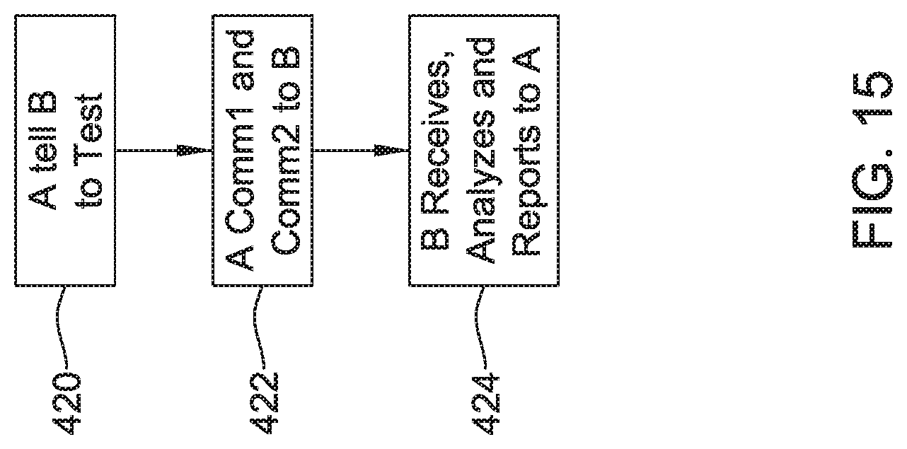
D00015

XML
uspto.report is an independent third-party trademark research tool that is not affiliated, endorsed, or sponsored by the United States Patent and Trademark Office (USPTO) or any other governmental organization. The information provided by uspto.report is based on publicly available data at the time of writing and is intended for informational purposes only.
While we strive to provide accurate and up-to-date information, we do not guarantee the accuracy, completeness, reliability, or suitability of the information displayed on this site. The use of this site is at your own risk. Any reliance you place on such information is therefore strictly at your own risk.
All official trademark data, including owner information, should be verified by visiting the official USPTO website at www.uspto.gov. This site is not intended to replace professional legal advice and should not be used as a substitute for consulting with a legal professional who is knowledgeable about trademark law.