Coupling units for medical device delivery systems
Nageswaran , et al. March 16, 2
U.S. patent number 10,945,867 [Application Number 16/459,118] was granted by the patent office on 2021-03-16 for coupling units for medical device delivery systems. This patent grant is currently assigned to COVIDIEN LP. The grantee listed for this patent is Covidien LP. Invention is credited to Aaron Barrett, Cong Dang, Ashok Nageswaran, James Phan.


| United States Patent | 10,945,867 |
| Nageswaran , et al. | March 16, 2021 |
Coupling units for medical device delivery systems
Abstract
A stent coupler for use with a medical device delivery system is disclosed. A stent delivery system includes a core member having a distal segment and a coupler positioned about the core member distal segment. the coupler is rotatably coupled to the core member and includes a rigid plate having a first end surface, a second end surface, and a side surface extending between the first and second end surfaces, the side surface comprising one or more projections separated by recesses. The delivery system further includes a stent extending along the core member distal segment such that an inner surface of the stent is engaged by the one or more projections of the engagement member.
| Inventors: | Nageswaran; Ashok (Irvine, CA), Dang; Cong (Garden Grove, CA), Barrett; Aaron (San Clemente, CA), Phan; James (Santa Ana, CA) | ||||||||||
|---|---|---|---|---|---|---|---|---|---|---|---|
| Applicant: |
|
||||||||||
| Assignee: | COVIDIEN LP (Mansfield,
MA) |
||||||||||
| Family ID: | 1000005422064 | ||||||||||
| Appl. No.: | 16/459,118 | ||||||||||
| Filed: | July 1, 2019 |
Prior Publication Data
| Document Identifier | Publication Date | |
|---|---|---|
| US 20190336312 A1 | Nov 7, 2019 | |
Related U.S. Patent Documents
| Application Number | Filing Date | Patent Number | Issue Date | ||
|---|---|---|---|---|---|
| 15410444 | Jan 19, 2017 | 10376396 | |||
| Current U.S. Class: | 1/1 |
| Current CPC Class: | A61F 2/90 (20130101); A61F 2/95 (20130101); A61F 2/966 (20130101); A61F 2002/9665 (20130101); A61F 2230/0069 (20130101); A61F 2002/823 (20130101); A61F 2/86 (20130101); A61F 2002/9505 (20130101) |
| Current International Class: | A61F 2/90 (20130101); A61F 2/95 (20130101); A61F 2/966 (20130101); A61F 2/82 (20130101); A61F 2/86 (20130101) |
References Cited [Referenced By]
U.S. Patent Documents
| 3416531 | December 1968 | Lowell |
| 4364391 | December 1982 | Toye |
| 4425919 | January 1984 | Alston, Jr. et al. |
| 4516972 | May 1985 | Samson |
| 4723936 | February 1988 | Buchbinder et al. |
| 4877031 | October 1989 | Conway et al. |
| 4990151 | February 1991 | Wallsten |
| 5011478 | April 1991 | Cope |
| 5026377 | June 1991 | Burton et al. |
| 5037404 | August 1991 | Gold et al. |
| 5061275 | October 1991 | Wallsten et al. |
| 5098393 | March 1992 | Amplatz et al. |
| 5108411 | April 1992 | Mckenzie |
| 5147370 | September 1992 | Mcnamara et al. |
| 5178158 | January 1993 | De Toledo |
| 5201316 | April 1993 | Pomeranz et al. |
| 5209734 | May 1993 | Hurley et al. |
| 5279562 | January 1994 | Sirhan et al. |
| 5279596 | January 1994 | Castaneda et al. |
| 5292311 | March 1994 | Cope |
| 5318032 | June 1994 | Lonsbury et al. |
| 5318525 | June 1994 | West et al. |
| 5318529 | June 1994 | Kontos |
| 5358493 | October 1994 | Schweich, Jr. et al. |
| 5382259 | January 1995 | Phelps et al. |
| 5403292 | April 1995 | Ju |
| 5437288 | August 1995 | Schwartz et al. |
| 5445646 | August 1995 | Euteneuer et al. |
| 5454795 | October 1995 | Samson |
| 5458605 | October 1995 | Klemm |
| 5474563 | December 1995 | Myler et al. |
| 5478349 | December 1995 | Nicholas |
| 5484444 | January 1996 | Braunschweiler et al. |
| 5496294 | March 1996 | Hergenrother et al. |
| 5499975 | March 1996 | Cope et al. |
| 5522822 | June 1996 | Phelps et al. |
| 5531721 | July 1996 | Pepin et al. |
| 5534007 | July 1996 | St Germain et al. |
| 5545209 | August 1996 | Roberts et al. |
| 5554139 | September 1996 | Okajima |
| 5569220 | October 1996 | Webster, Jr. |
| 5571135 | November 1996 | Fraser et al. |
| 5573520 | November 1996 | Schwartz et al. |
| 5584821 | December 1996 | Hobbs et al. |
| 5599325 | February 1997 | Ju et al. |
| 5599326 | February 1997 | Carter |
| 5601539 | February 1997 | Corso, Jr. |
| 5636641 | June 1997 | Fariabi |
| 5645559 | July 1997 | Hachtman et al. |
| 5658264 | August 1997 | Samson |
| 5662622 | September 1997 | Gore et al. |
| 5676659 | October 1997 | Mcgurk |
| 5695483 | December 1997 | Samson |
| 5695499 | December 1997 | Helgerson et al. |
| 5702373 | December 1997 | Samson |
| 5702418 | December 1997 | Ravenscroft |
| 5704926 | January 1998 | Sutton |
| 5709703 | January 1998 | Lukic et al. |
| 5711909 | January 1998 | Gore et al. |
| 5725513 | March 1998 | Ju et al. |
| 5725571 | March 1998 | Imbert et al. |
| 5728063 | March 1998 | Preissman et al. |
| 5741429 | April 1998 | Donadio, III et al. |
| 5743876 | April 1998 | Swanson |
| 5759173 | June 1998 | Preissman et al. |
| 5776141 | July 1998 | Klein et al. |
| 5782811 | July 1998 | Samson et al. |
| 5791036 | August 1998 | Goodin et al. |
| 5824041 | October 1998 | Lenker et al. |
| 5833632 | November 1998 | Jacobsen et al. |
| 5836925 | November 1998 | Soltesz |
| 5836926 | November 1998 | Peterson et al. |
| 5851203 | December 1998 | Van Muiden |
| 5853400 | December 1998 | Samson |
| 5873866 | February 1999 | Kondo et al. |
| 5876386 | March 1999 | Samson |
| 5891112 | April 1999 | Samson |
| 5897529 | April 1999 | Ponzi |
| 5897537 | April 1999 | Berg et al. |
| 5902290 | May 1999 | Peacock, III et al. |
| 5906605 | May 1999 | Coxum |
| 5935161 | August 1999 | Robinson et al. |
| 5938653 | August 1999 | Pepin |
| 5951494 | September 1999 | Wang et al. |
| 5951539 | September 1999 | Nita et al. |
| 5961510 | October 1999 | Fugoso et al. |
| 5968053 | October 1999 | Revelas |
| 5968069 | October 1999 | Dusbabek et al. |
| 5971975 | October 1999 | Mills et al. |
| 6017323 | January 2000 | Chee |
| 6030371 | February 2000 | Pursley |
| 6045547 | April 2000 | Ren et al. |
| 6053903 | April 2000 | Samson |
| 6053904 | April 2000 | Scribner et al. |
| 6077258 | June 2000 | Lange et al. |
| 6077295 | June 2000 | Limon et al. |
| 6077297 | June 2000 | Robinson et al. |
| 6083152 | July 2000 | Strong |
| 6093177 | July 2000 | Javier, Jr. et al. |
| 6105651 | August 2000 | Leanna |
| 6106510 | August 2000 | Lunn et al. |
| 6106540 | August 2000 | Dehdashtian et al. |
| 6123723 | September 2000 | Konya et al. |
| 6126685 | October 2000 | Lenker et al. |
| 6135992 | October 2000 | Wang |
| 6149680 | November 2000 | Shelso et al. |
| 6152912 | November 2000 | Jansen et al. |
| 6152944 | November 2000 | Holman et al. |
| 6159219 | December 2000 | Ren |
| 6165163 | December 2000 | Chien et al. |
| 6165166 | December 2000 | Samuelson et al. |
| 6171295 | January 2001 | Garabedian et al. |
| 6171296 | January 2001 | Chow |
| 6171297 | January 2001 | Pedersen et al. |
| 6186986 | February 2001 | Berg et al. |
| 6193739 | February 2001 | Chevillon et al. |
| 6197015 | March 2001 | Wilson |
| 6217565 | April 2001 | Cohen |
| 6217566 | April 2001 | Ju et al. |
| 6251132 | June 2001 | Ravenscroft et al. |
| 6258080 | July 2001 | Samson |
| 6264683 | July 2001 | Stack et al. |
| 6287315 | September 2001 | Wijeratne et al. |
| 6325807 | December 2001 | Que |
| 6350278 | February 2002 | Lenker et al. |
| 6355027 | March 2002 | Le et al. |
| 6358238 | March 2002 | Sherry |
| 6358460 | March 2002 | Hunt, Jr. et al. |
| 6368316 | April 2002 | Jansen et al. |
| 6371953 | April 2002 | Beyar et al. |
| 6383171 | May 2002 | Gifford et al. |
| 6387118 | May 2002 | Hanson |
| 6389087 | May 2002 | Heinonen et al. |
| 6395008 | May 2002 | Ellis et al. |
| 6395017 | May 2002 | Dwyer et al. |
| 6398791 | June 2002 | Que et al. |
| 6419693 | July 2002 | Fariabi |
| 6425898 | July 2002 | Wilson et al. |
| 6428552 | August 2002 | Sparks |
| 6443971 | September 2002 | Boylan et al. |
| 6458075 | October 2002 | Sugiyama et al. |
| 6464684 | October 2002 | Galdonik |
| 6468298 | October 2002 | Pelton |
| 6475184 | November 2002 | Wang et al. |
| 6494907 | December 2002 | Bulver |
| 6508804 | January 2003 | Sarge et al. |
| 6508805 | January 2003 | Garabedian et al. |
| 6508806 | January 2003 | Hoste |
| 6517547 | February 2003 | Feeser et al. |
| 6554820 | April 2003 | Wendlandt et al. |
| 6562021 | May 2003 | Derbin et al. |
| 6562063 | May 2003 | Euteneuer et al. |
| 6576006 | June 2003 | Limon et al. |
| 6582460 | June 2003 | Cryer |
| 6589227 | July 2003 | Soenderskov |
| 6602271 | August 2003 | Adams et al. |
| 6607551 | August 2003 | Sullivan et al. |
| 6622367 | September 2003 | Bolduc et al. |
| 6635047 | October 2003 | Forsberg |
| 6638245 | October 2003 | Miller et al. |
| 6641564 | November 2003 | Kraus |
| 6648654 | November 2003 | Hembree |
| 6648874 | November 2003 | Parisi et al. |
| 6652508 | November 2003 | Griffin et al. |
| 6663614 | December 2003 | Carter |
| 6669719 | December 2003 | Wallace et al. |
| 6689120 | February 2004 | Gerdts |
| 6699274 | March 2004 | Stinson |
| 6702782 | March 2004 | Miller et al. |
| 6706055 | March 2004 | Douk et al. |
| 6716207 | April 2004 | Farnholtz |
| 6726659 | April 2004 | Stocking et al. |
| 6764504 | July 2004 | Wang et al. |
| 6808529 | October 2004 | Fulkerson |
| 6814749 | November 2004 | Cox et al. |
| 6815325 | November 2004 | Ishii |
| 6817995 | November 2004 | Halpern |
| 6830575 | December 2004 | Stenzel et al. |
| 6837890 | January 2005 | Chludzinski et al. |
| 6843802 | January 2005 | Villalobos et al. |
| 6858024 | February 2005 | Berg et al. |
| 6866660 | March 2005 | Garabedian et al. |
| 6866679 | March 2005 | Kusleika |
| 6932837 | August 2005 | Amplatz et al. |
| 6939353 | September 2005 | Que et al. |
| 6945970 | September 2005 | Pepin |
| 6960227 | November 2005 | Jones et al. |
| 6984963 | January 2006 | Pidutti et al. |
| 6989024 | January 2006 | Hebert et al. |
| 7001369 | February 2006 | Griffin et al. |
| 7011675 | March 2006 | Hemerick et al. |
| 7025758 | April 2006 | Klint |
| 7074236 | July 2006 | Rabkin et al. |
| 7104979 | September 2006 | Jansen et al. |
| 7147656 | December 2006 | Andreas et al. |
| 7156860 | January 2007 | Wallsten |
| 7163523 | January 2007 | Devens, Jr. et al. |
| 7166088 | January 2007 | Heuser |
| 7166099 | January 2007 | Devens, Jr. |
| 7166100 | January 2007 | Jordan et al. |
| 7172575 | February 2007 | El-nounou et al. |
| 7223263 | May 2007 | Seno |
| 7228878 | June 2007 | Chen et al. |
| 7306624 | December 2007 | Yodfat et al. |
| 7323000 | January 2008 | Monstdt et al. |
| 7331948 | February 2008 | Skarda |
| 7357812 | April 2008 | Andreas et al. |
| 7371248 | May 2008 | Dapolito et al. |
| 7402151 | July 2008 | Rosenman et al. |
| 7404820 | July 2008 | Mazzocchi et al. |
| 7427288 | September 2008 | Sater |
| 7438712 | October 2008 | Chouinard |
| 7445684 | November 2008 | Pursley |
| 7473271 | January 2009 | Gunderson |
| 7473272 | January 2009 | Pryor |
| 7481804 | January 2009 | Devens, Jr. |
| 7507229 | March 2009 | Hewitt et al. |
| 7524322 | April 2009 | Monstdt et al. |
| 7556634 | July 2009 | Lee et al. |
| 7556710 | July 2009 | Leeflang et al. |
| 7569046 | August 2009 | Zhou |
| 7572290 | August 2009 | Yodfat et al. |
| 7582079 | September 2009 | Wendlandt et al. |
| 7597830 | October 2009 | Zhou |
| 7621904 | November 2009 | Mcferran et al. |
| 7641646 | January 2010 | Kennedy, II |
| 7651520 | January 2010 | Fischell et al. |
| 7655031 | February 2010 | Tenne et al. |
| 7674411 | March 2010 | Berg et al. |
| 7691138 | April 2010 | Stenzel et al. |
| 7708704 | May 2010 | Mitelberg et al. |
| 7717953 | May 2010 | Kaplan et al. |
| 7740652 | June 2010 | Gerdts et al. |
| 7758624 | July 2010 | Dorn et al. |
| 7766820 | August 2010 | Core |
| 7766896 | August 2010 | Kornkven et al. |
| 7780646 | August 2010 | Farnholtz |
| 7815600 | October 2010 | Al-marashi et al. |
| 7815608 | October 2010 | Schafersman et al. |
| 7815628 | October 2010 | Devens, Jr. |
| 7828790 | November 2010 | Griffin |
| 7867267 | January 2011 | Sullivan et al. |
| 7879022 | February 2011 | Bonnette et al. |
| 7935140 | May 2011 | Griffin |
| 7942925 | May 2011 | Yodfat et al. |
| 7955370 | June 2011 | Gunderson |
| 7981148 | July 2011 | Aguilar et al. |
| 7993385 | August 2011 | Levine et al. |
| 8025692 | September 2011 | Feeser |
| 8034095 | October 2011 | Randolph et al. |
| 8042720 | October 2011 | Shifrin et al. |
| 8048104 | November 2011 | Monstadt et al. |
| 8066754 | November 2011 | Malewicz |
| 8083791 | December 2011 | Kaplan et al. |
| 8088140 | January 2012 | Ferrera et al. |
| 8092508 | January 2012 | Leynov et al. |
| 8109987 | February 2012 | Kaplan et al. |
| 8133266 | March 2012 | Thomas et al. |
| 8147534 | April 2012 | Berez et al. |
| 8187314 | May 2012 | Davis et al. |
| 8257432 | September 2012 | Kaplan et al. |
| 8298276 | October 2012 | Ozawa et al. |
| 8317850 | November 2012 | Kusleika |
| 8337543 | December 2012 | Jordan et al. |
| 8366763 | February 2013 | Davis et al. |
| 8382818 | February 2013 | Davis et al. |
| 8480701 | July 2013 | Monstadt |
| 8579958 | November 2013 | Kusleika |
| 8591566 | November 2013 | Newell et al. |
| 8597321 | December 2013 | Monstadt et al. |
| 8636760 | January 2014 | Garcia et al. |
| 8679172 | March 2014 | Dorn et al. |
| 8790387 | July 2014 | Nguyen et al. |
| 8858613 | October 2014 | Cragg et al. |
| 8968383 | March 2015 | Johnson et al. |
| 9393141 | July 2016 | Gerdts et al. |
| 9439795 | September 2016 | Wang et al. |
| 2001/0020173 | September 2001 | Klumb et al. |
| 2001/0027310 | October 2001 | Parisi et al. |
| 2001/0029362 | October 2001 | Sirhan et al. |
| 2001/0044591 | November 2001 | Stevens et al. |
| 2001/0049547 | December 2001 | Moore |
| 2002/0029046 | March 2002 | Lorentzen et al. |
| 2002/0045929 | April 2002 | Diaz |
| 2002/0049412 | April 2002 | Madrid et al. |
| 2002/0072789 | June 2002 | Hackett et al. |
| 2002/0107526 | August 2002 | Greenberg et al. |
| 2002/0111666 | August 2002 | Hart et al. |
| 2002/0138128 | September 2002 | Stiger et al. |
| 2002/0156459 | October 2002 | Ye et al. |
| 2002/0156460 | October 2002 | Ye et al. |
| 2002/0165523 | November 2002 | Chin et al. |
| 2002/0188342 | December 2002 | Rykhus et al. |
| 2003/0004539 | January 2003 | Linder et al. |
| 2003/0009208 | January 2003 | Snyder et al. |
| 2003/0050600 | March 2003 | Ressemann et al. |
| 2003/0191451 | October 2003 | Gilmartin |
| 2003/0212410 | November 2003 | Stenzel et al. |
| 2003/0212430 | November 2003 | Bose et al. |
| 2004/0024416 | February 2004 | Yodfat et al. |
| 2004/0092879 | May 2004 | Kraus et al. |
| 2004/0111095 | June 2004 | Gordon et al. |
| 2004/0143239 | July 2004 | Zhou et al. |
| 2004/0147903 | July 2004 | Latini |
| 2004/0158230 | August 2004 | Hunn et al. |
| 2004/0181174 | September 2004 | Davis et al. |
| 2004/0193140 | September 2004 | Griffin et al. |
| 2004/0193243 | September 2004 | Mangiardi et al. |
| 2004/0204749 | October 2004 | Gunderson |
| 2004/0220585 | November 2004 | Nikolchev et al. |
| 2004/0230285 | November 2004 | Gifford et al. |
| 2004/0260271 | December 2004 | Huyser et al. |
| 2004/0260384 | December 2004 | Allen |
| 2005/0033403 | February 2005 | Ward et al. |
| 2005/0070794 | March 2005 | Deal et al. |
| 2005/0090802 | April 2005 | Connors et al. |
| 2005/0096724 | May 2005 | Stenzel et al. |
| 2005/0119719 | June 2005 | Wallace et al. |
| 2005/0125051 | June 2005 | Eidenschink et al. |
| 2005/0131449 | June 2005 | Salahieh et al. |
| 2005/0143773 | June 2005 | Abrams et al. |
| 2005/0149160 | July 2005 | Mcferran |
| 2005/0182388 | August 2005 | Garabedian et al. |
| 2005/0182475 | August 2005 | Jen et al. |
| 2005/0228361 | October 2005 | Tremaglio |
| 2005/0240254 | October 2005 | Austin |
| 2005/0273149 | December 2005 | Tran et al. |
| 2005/0277949 | December 2005 | Que et al. |
| 2006/0030835 | February 2006 | Sherman et al. |
| 2006/0036309 | February 2006 | Hebert et al. |
| 2006/0058865 | March 2006 | Case et al. |
| 2006/0064123 | March 2006 | Bonnette et al. |
| 2006/0074477 | April 2006 | Berthiaume et al. |
| 2006/0089618 | April 2006 | Mcferran et al. |
| 2006/0095050 | May 2006 | Hartley et al. |
| 2006/0100687 | May 2006 | Fahey et al. |
| 2006/0100688 | May 2006 | Jordan et al. |
| 2006/0116750 | June 2006 | Hebert et al. |
| 2006/0129166 | June 2006 | Lavelle |
| 2006/0178698 | August 2006 | Mcintyre et al. |
| 2006/0184226 | August 2006 | Austin |
| 2006/0212042 | September 2006 | Lamport et al. |
| 2006/0217682 | September 2006 | Stivland et al. |
| 2006/0235502 | October 2006 | Belluche et al. |
| 2007/0027520 | February 2007 | Sherburne |
| 2007/0043430 | February 2007 | Stinson |
| 2007/0049903 | March 2007 | Jansen et al. |
| 2007/0078504 | April 2007 | Mialhe |
| 2007/0088323 | April 2007 | Campbell et al. |
| 2007/0100421 | May 2007 | Griffin |
| 2007/0117645 | May 2007 | Nakashima |
| 2007/0129706 | June 2007 | Katoh et al. |
| 2007/0149927 | June 2007 | Itou et al. |
| 2007/0161956 | July 2007 | Heuser |
| 2007/0185446 | August 2007 | Accisano |
| 2007/0203563 | August 2007 | Hebert et al. |
| 2007/0233224 | October 2007 | Leynov et al. |
| 2007/0239254 | October 2007 | Chia et al. |
| 2007/0239261 | October 2007 | Bose et al. |
| 2007/0250039 | October 2007 | Lobbins et al. |
| 2007/0250040 | October 2007 | Provost et al. |
| 2007/0255255 | November 2007 | Shah et al. |
| 2007/0255388 | November 2007 | Rudakov et al. |
| 2007/0270779 | November 2007 | Jacobs et al. |
| 2007/0299424 | December 2007 | Cumming et al. |
| 2007/0299500 | December 2007 | Hebert et al. |
| 2007/0299501 | December 2007 | Hebert et al. |
| 2007/0299502 | December 2007 | Hebert et al. |
| 2008/0009934 | January 2008 | Schneider et al. |
| 2008/0015558 | January 2008 | Harlan |
| 2008/0015678 | January 2008 | Kaplan et al. |
| 2008/0027528 | January 2008 | Jagger et al. |
| 2008/0033399 | February 2008 | Hunn et al. |
| 2008/0033528 | February 2008 | Satasiya et al. |
| 2008/0051705 | February 2008 | Von Oepen et al. |
| 2008/0051761 | February 2008 | Slazas et al. |
| 2008/0071301 | March 2008 | Matsuura et al. |
| 2008/0077229 | March 2008 | Andreas et al. |
| 2008/0082083 | April 2008 | Forde et al. |
| 2008/0091169 | April 2008 | Heideman et al. |
| 2008/0097398 | April 2008 | Mitelberg et al. |
| 2008/0108974 | May 2008 | Yee |
| 2008/0132933 | June 2008 | Gerber |
| 2008/0140180 | June 2008 | Dolan et al. |
| 2008/0147001 | June 2008 | Al-marashi et al. |
| 2008/0147162 | June 2008 | Andreas et al. |
| 2008/0177249 | July 2008 | Heuser et al. |
| 2008/0188865 | August 2008 | Miller et al. |
| 2008/0188928 | August 2008 | Salahieh et al. |
| 2008/0221666 | September 2008 | Licata et al. |
| 2008/0234660 | September 2008 | Cumming et al. |
| 2008/0234795 | September 2008 | Snow et al. |
| 2008/0243225 | October 2008 | Satasiya et al. |
| 2008/0255541 | October 2008 | Hoffman et al. |
| 2008/0255653 | October 2008 | Schkolnik |
| 2008/0255654 | October 2008 | Hebert et al. |
| 2008/0262471 | October 2008 | Warnock |
| 2008/0262472 | October 2008 | Lunn et al. |
| 2008/0262592 | October 2008 | Jordan et al. |
| 2008/0275426 | November 2008 | Holman et al. |
| 2008/0300667 | December 2008 | Hebert et al. |
| 2008/0312639 | December 2008 | Weber |
| 2009/0012500 | January 2009 | Murata et al. |
| 2009/0082609 | March 2009 | Condado |
| 2009/0105802 | April 2009 | Henry et al. |
| 2009/0125053 | May 2009 | Ferrera et al. |
| 2009/0132019 | May 2009 | Duffy et al. |
| 2009/0138066 | May 2009 | Leopold et al. |
| 2009/0143849 | June 2009 | Ozawa et al. |
| 2009/0149835 | June 2009 | Velasco et al. |
| 2009/0157048 | June 2009 | Sutermeister et al. |
| 2009/0160112 | June 2009 | Ostrovsky |
| 2009/0171319 | July 2009 | Guo et al. |
| 2009/0204196 | August 2009 | Weber |
| 2009/0240235 | September 2009 | Murata |
| 2009/0264985 | October 2009 | Bruszewski |
| 2009/0287182 | November 2009 | Bishop et al. |
| 2009/0287183 | November 2009 | Bishop et al. |
| 2009/0287187 | November 2009 | Legaspi et al. |
| 2009/0287292 | November 2009 | Becking et al. |
| 2009/0299333 | December 2009 | Wendlandt et al. |
| 2009/0299449 | December 2009 | Styrc |
| 2009/0318947 | December 2009 | Garcia et al. |
| 2010/0020354 | January 2010 | Ito |
| 2010/0036363 | February 2010 | Watanabe et al. |
| 2010/0049293 | February 2010 | Zukowski et al. |
| 2010/0049297 | February 2010 | Dorn |
| 2010/0057184 | March 2010 | Randolph et al. |
| 2010/0057185 | March 2010 | Melsheimer et al. |
| 2010/0069852 | March 2010 | Kelley |
| 2010/0087913 | April 2010 | Rabkin et al. |
| 2010/0094258 | April 2010 | Shimogami et al. |
| 2010/0094394 | April 2010 | Beach et al. |
| 2010/0094395 | April 2010 | Kellett |
| 2010/0100106 | April 2010 | Ferrera |
| 2010/0160863 | June 2010 | Heuser |
| 2010/0198334 | August 2010 | Yodfat et al. |
| 2010/0204770 | August 2010 | Mas et al. |
| 2010/0217235 | August 2010 | Thorstenson et al. |
| 2010/0256602 | October 2010 | Lippert et al. |
| 2010/0256603 | October 2010 | Lippert et al. |
| 2010/0262157 | October 2010 | Silver et al. |
| 2010/0268243 | October 2010 | Parker |
| 2010/0268328 | October 2010 | Stiger |
| 2010/0274270 | October 2010 | Patel et al. |
| 2010/0298931 | November 2010 | Quadri et al. |
| 2010/0331951 | December 2010 | Bei et al. |
| 2011/0009943 | January 2011 | Paul et al. |
| 2011/0022157 | January 2011 | Essinger et al. |
| 2011/0029065 | February 2011 | Wood et al. |
| 2011/0034987 | February 2011 | Kennedy |
| 2011/0054586 | March 2011 | Mayberry et al. |
| 2011/0093055 | April 2011 | Kujawski |
| 2011/0098804 | April 2011 | Yeung et al. |
| 2011/0106235 | May 2011 | Haverkost et al. |
| 2011/0112623 | May 2011 | Schatz |
| 2011/0137403 | June 2011 | Rasmussen et al. |
| 2011/0152760 | June 2011 | Parker |
| 2011/0160763 | June 2011 | Ferrera et al. |
| 2011/0178588 | July 2011 | Haselby |
| 2011/0190862 | August 2011 | Bashiri et al. |
| 2011/0190865 | August 2011 | Mchugo et al. |
| 2011/0208292 | August 2011 | Von Oepen et al. |
| 2011/0224650 | September 2011 | Itou et al. |
| 2011/0257720 | October 2011 | Peterson et al. |
| 2011/0288626 | November 2011 | Straubinger et al. |
| 2011/0319904 | December 2011 | Hollett et al. |
| 2012/0029607 | February 2012 | Mchugo et al. |
| 2012/0035700 | February 2012 | Leanna et al. |
| 2012/0053681 | March 2012 | Alkhatib et al. |
| 2012/0059449 | March 2012 | Dorn et al. |
| 2012/0065660 | March 2012 | Ferrera et al. |
| 2012/0116494 | May 2012 | Leynov et al. |
| 2012/0123511 | May 2012 | Brown |
| 2012/0226343 | September 2012 | Vo et al. |
| 2012/0253447 | October 2012 | Hayasaka et al. |
| 2012/0316638 | December 2012 | Grad et al. |
| 2013/0085562 | April 2013 | Rincon et al. |
| 2013/0131775 | May 2013 | Hadley et al. |
| 2013/0172925 | July 2013 | Garcia et al. |
| 2013/0172979 | July 2013 | Fargahi |
| 2013/0226276 | August 2013 | Newell et al. |
| 2013/0226278 | August 2013 | Newell et al. |
| 2013/0261730 | October 2013 | Bose et al. |
| 2013/0274618 | October 2013 | Hou et al. |
| 2013/0274859 | October 2013 | Argentine |
| 2013/0282099 | October 2013 | Huynh |
| 2013/0304185 | November 2013 | Newell et al. |
| 2014/0025150 | January 2014 | Lim |
| 2014/0031918 | January 2014 | Newell et al. |
| 2014/0148893 | May 2014 | Kusleika |
| 2014/0171826 | June 2014 | Lampropoulos et al. |
| 2014/0172067 | June 2014 | Brown et al. |
| 2014/0194919 | July 2014 | Losordo et al. |
| 2014/0200648 | July 2014 | Newell et al. |
| 2014/0277332 | September 2014 | Slazas et al. |
| 2015/0032198 | January 2015 | Folk |
| 2015/0066128 | March 2015 | Losordo et al. |
| 2015/0066129 | March 2015 | Nageswaran et al. |
| 2015/0066130 | March 2015 | Haggstrom et al. |
| 2015/0066131 | March 2015 | Luong et al. |
| 2015/0080937 | March 2015 | Davidson |
| 2015/0133990 | May 2015 | Davidson |
| 2015/0164666 | June 2015 | Johnson et al. |
| 2015/0238336 | August 2015 | Johnson et al. |
| 2016/0113793 | April 2016 | Nishigishi |
| 2017/0035592 | February 2017 | Haggstrom et al. |
| 2018/0200092 | July 2018 | Nageswaran et al. |
| 2018/0263799 | September 2018 | Elwood et al. |
| 2019/0314175 | October 2019 | Dawson et al. |
| 2019/0314176 | October 2019 | Nageswaran et al. |
| 2019/0314177 | October 2019 | Alonso et al. |
| 2019/0314179 | October 2019 | Nageswaran et al. |
| 104582643 | Apr 2015 | CN | |||
| 105232195 | Jan 2016 | CN | |||
| 2001504016 | Mar 2001 | JP | |||
| 2008518717 | Jun 2008 | JP | |||
| 2009542357 | Dec 2009 | JP | |||
| 2013500777 | Jan 2013 | JP | |||
| 2013158647 | Aug 2013 | JP | |||
| WO 9820811 | May 1998 | WO | |||
| WO 2010127838 | Nov 2010 | WO | |||
| WO 2011076408 | Jun 2011 | WO | |||
| WO 2011081997 | Jul 2011 | WO | |||
| 2011122444 | Oct 2011 | WO | |||
| WO 2012158152 | Nov 2012 | WO | |||
| 2014074462 | May 2014 | WO | |||
Other References
|
Search Report dated Mar. 24, 2020, CN Application No. 201880007614.9, 10 pages. cited by applicant. |
Primary Examiner: Ulsh; George J
Assistant Examiner: Restaino; Andrew P.
Attorney, Agent or Firm: Fortem IP LLP Lincicum; Matthew
Claims
We claim:
1. A stent delivery system, comprising: a core member having a distal segment; a coupling unit positioned about the core member distal segment, the coupling unit comprising: a proximal restraint coupled to the core member distal segment; a distal restraint coupled to the core member distal segment at a position distal to the proximal restraint; two or more plates slidably coupled to the core member distal segment between the proximal restraint and the distal restraint; and one or more spacers coupled to the core member distal segment between the proximal restraint and the distal restraint, wherein the proximal restraint and the distal restraint are spaced apart along the core member by a longitudinal distance that is greater than the combined length of the two or more plates and the one or more spacers coupled to the core member distal segment between the proximal restraint and the distal restraint; and a stent extending along the core member distal segment such that an inner surface of the stent is engaged by at least one of the plates.
2. The stent delivery system of claim 1, wherein the longitudinal distance is such that plates can slide longitudinally along the core member distal segment with respect to the proximal and distal restraints.
3. The stent delivery system of claim 1, wherein the one or more spacers comprises a spacer disposed between two plates.
4. The stent delivery system of claim 1, wherein: the two or more plates comprise first, second, and third plates, the one or more spacers comprise first and second spacers, and the first spacer is disposed between the first and second plates and the second spacer is disposed between the second and third plates.
5. The stent delivery system of claim 4, wherein the proximal restraint and the distal restraint are spaced apart along the core member by a longitudinal distance that is greater than the combined length of the first, second, and third plates and the first and second spacers.
6. The stent delivery system of claim 1, wherein at least one projection of the two or more plates is interlocked with the stent such that the projection is at least partially received within a pore of the stent.
7. The stent delivery system of claim 1, wherein the two or more plates are spaced apart from one another by a distance corresponding to a distance between centers of longitudinally adjacent pores of the stent.
8. A stent delivery system, comprising: a catheter having a lumen and an inner surface extending along the lumen; a core member, extending within the catheter lumen; first and second couplers slidably mounted to the core member, each of the first and second couplers comprising: a first end surface, a second end surface, and a side surface extending between the first end surface and the second end surface; and an aperture extending through the first and second end surfaces, the core member and extending through the aperture, the aperture defining a radial gap between an outer surface of the core member and an inner surface of the coupler; one or more spacers mounted on the core member; a proximal restraint mounted on the core member at a position proximal to the first coupler, the second coupler, and the one or more spacers; a distal restraint mounted on the core member at a position distal to the first coupler, the second coupler, and the one or more spacers, the distal restraint spaced apart from the proximal restraint by a longitudinal distance greater than the combined length of the first and second couplers and the one or more spacers; and a stent extending along the core member and disposed radially between the catheter inner surface and the first and second couplers.
9. The stent delivery system of claim 8, wherein the stent comprises a mesh forming a plurality of pores, and wherein the first and second couplers are spaced apart from one another by a distance corresponding to a distance between centers of longitudinally adjacent pores of the stent.
10. The stent delivery system of claim 8, wherein a radially outermost dimension of the spacer is smaller than a radially outermost dimension of the first coupler and the second coupler.
11. The stent delivery system of claim 8, wherein the one or more spacers are fixed with respect to the core member.
12. The stent delivery system of claim 8, wherein the one or more spacers comprises a spacer disposed between the first coupler and the second coupler.
13. The stent delivery system of claim 8, further comprising a third coupler slidably mounted to the core member, wherein: the one or more spacers comprise first and second spacers, and the first spacer is disposed between the first and second couplers and the second spacer is disposed between the second and third couplers.
14. The stent delivery system of claim 8, wherein a side surface of the first coupler and a side surface of the second coupler each comprise one or more projections separated by recesses.
15. An assembly configured to engage a stent, comprising: a core member; a proximal restraint mounted on the core member; a distal restraint mounted on the core member at a position distal the proximal restraint; a first coupler slidably coupled to the core member between the proximal restraint and the distal restraint; a second coupler slidably coupled to the core member at a position between the proximal restraint and the distal restraint; and one or more spacers coupled to the core member at a position between the proximal restraint and the distal restraint, wherein the proximal and distal restraints are spaced apart along the core member by a longitudinal distance that is greater than a combined length of the first and second couplers and the one or more spacers.
16. The assembly of claim 15, wherein a radially outermost dimension of the spacer is smaller than a radially outermost dimension of the first coupler and the second coupler.
17. The assembly of claim 15, wherein the one or more spacers comprises a spacer disposed between the first couplers and the second coupler.
18. The assembly of claim 15, wherein the first coupler and the second coupler each comprise: a first end surface, a second end surface, and a side surface comprising one or more projections extending between the first end surface and the second end surface; and an aperture extending through the first and second end surfaces, the core member extending through the aperture, the aperture defining a radial gap between an outer surface of the core member and an inner surface of the coupler.
19. The assembly of claim 18, wherein the projections comprise rounded edges.
20. The assembly of claim 15, wherein the one or more spacers comprises a spacer disposed between first and second couplers.
21. The assembly of claim 15, further comprising a third coupler slidably mounted to the core member, wherein: the one or more spacers comprise first and second spacers, and the first spacer is disposed between the first and second couplers and the second spacer is disposed between the second and third couplers.
22. The assembly of claim 21, wherein the proximal restraint and the distal restraint are spaced apart along the core member by a longitudinal distance that is greater than the combined length of the first, second, and third couplers and the first and second spacers.
Description
CROSS-REFERENCE TO RELATED APPLICATION(S)
The present application claims the benefit of U.S. patent application Ser. No. 15/410,444, filed Jan. 19, 2017, which is incorporated herein by reference in its entirety.
BACKGROUND
Walls of the vasculature, particularly arterial walls, may develop areas of pathological dilatation called aneurysms that often have thin, weak walls that are prone to rupturing. Aneurysms are generally caused by weakening of the vessel wall due to disease, injury, or a congenital abnormality. Aneurysms occur in different parts of the body, and the most common are abdominal aortic aneurysms and cerebral (e.g., brain) aneurysms in the neurovasculature. When the weakened wall of an aneurysm ruptures, it can result in death, especially if it is a cerebral aneurysm that ruptures.
Aneurysms are generally treated by excluding or at least partially isolating the weakened part of the vessel from the arterial circulation. For example, conventional aneurysm treatments include: (i) surgical clipping, where a metal clip is secured around the base of the aneurysm; (ii) packing the aneurysm with small, flexible wire coils (micro-coils); (iii) using embolic materials to "fill" an aneurysm; (iv) using detachable balloons or coils to occlude the parent vessel that supplies the aneurysm; and (v) intravascular stenting.
Intravascular stents are well known in the medical arts for the treatment of vascular stenoses or aneurysms. Stents are prostheses that expand radially or otherwise within a vessel or lumen to support the vessel from collapsing. Methods for delivering these intravascular stents are also well known.
Conventional methods of introducing a compressed stent into a vessel and positioning it within an area of stenosis or an aneurysm include percutaneously advancing a distal portion of a guiding catheter through the vascular system of a patient until the distal portion is proximate the stenosis or aneurysm. A second, inner catheter and a guidewire within the inner catheter are advanced through the distal region of the guiding catheter. The guidewire is then advanced out of the distal region of the guiding catheter into the vessel until the distal portion of the guidewire carrying the compressed stent is positioned at the point of the lesion within the vessel. The compressed stent is then released and expanded so that it supports the vessel at the point of the lesion.
SUMMARY
The present technology is illustrated, for example, according to various aspects described below. Various examples of aspects of the present technology are described as numbered clauses (1, 2, 3, etc.) for convenience. These are provided as examples and do not limit the present technology. It is noted that any of the dependent clauses may be combined in any combination, and placed into a respective independent clause, e.g., Clause 1 or Clause 23. The other clauses can be presented in a similar manner.
1. A stent delivery system, comprising: a core member having a distal segment; a coupler positioned about the core member distal segment and rotatably coupled to the core member, the coupler comprising a rigid plate having a first end surface, a second end surface, and a side surface extending between the first and second end surfaces, the side surface comprising one or more projections separated by recesses; and a stent extending along the core member distal segment such that an inner surface of the stent is engaged by the one or more projections of the coupler.
2. The stent delivery system of Clause 1, wherein the projections comprise rounded edges.
3. The stent delivery system of Clause 1, wherein the one or more projections comprises three or more projections.
4. The stent delivery system of Clause 1, wherein a longest dimension of the first and second end surfaces is configured to fit within a 0.017'', 0.021'' or 0.027'' inner diameter catheter.
5. The stent delivery system of Clause 1, wherein a maximum length of the first and second end surfaces is at least 5 times greater than a length of the side surface, the maximum length of the first and second end surfaces being generally orthogonal to the length of the side surface.
6. The stent delivery system of Clause 1, wherein the rigid plate comprises at least one of a metal or a rigid polymer.
7. The stent delivery system of Clause 1, wherein the rigid plate side surface has a length of between about 25-100 microns.
8. The stent delivery system of Clause 1, wherein the rigid plate is a first rigid plate, the stent delivery system further comprising: a second rigid plate positioned about the core member distal segment and spaced apart from the first rigid plate; and a spacer positioned about the core member distal segment, the spacer positioned between the first rigid plate and the second rigid plate.
9. The stent delivery system of Clause 8, wherein the spacer comprises a cylindrical body having end walls orthogonal to a long axis of the core member.
10. The stent delivery system of Clause 8, wherein the first and second rigid plates are spaced apart from one another by a distance corresponding to a pore pitch of the stent.
11. The stent delivery system of Clause 1, wherein the first and second end surfaces are substantially orthogonal to a long axis of the core member.
12. The stent delivery system of Clause 1, wherein the projections interlock with the stent such that each projection is at least partially received within a pore of the stent.
13. A stent delivery system, comprising: a catheter having a lumen and an inner surface extending along the lumen; a core member, extending within the catheter lumen; a plate comprising: a first end surface, a second end surface, and a side surface extending between the first end surface and the second end surface; and an aperture extending through the first and second end surfaces, the core member extending through the aperture such that the plate can rotate about the core member; and a stent extending along the core member and over the plate, at least a portion of the stent being radially positioned between the plate side surface and the catheter inner surface.
14. The stent delivery system of Clause 13, wherein the plate side surface comprises a plurality of projections separated by recesses.
15. The stent delivery system of Clause 14, wherein the projections interlock with the stent such that each projection is at least partially received within a pore of the stent.
16. The stent delivery system of Clause 14, wherein the one or more projections comprises three or more projections.
17. The stent delivery system of Clause 13, wherein a maximum length of the first and second end surfaces is at least 5 times greater than a length of the side surface, the maximum length of the first and second end surfaces being generally orthogonal to the length of the side surface.
18. The stent delivery system of Clause 13, wherein the plate comprises at least one of a metal or a rigid polymer.
19. The stent delivery system of Clause 13, wherein the plate is a first plate, the stent delivery system further comprising: a second plate positioned about the core member and spaced apart from the first plate; and a spacer positioned about the core member and positioned between the first plate and the second plate.
20. The stent delivery system of Clause 19, wherein the spacer comprises a cylindrical body having end walls orthogonal to a long axis of the core member.
21. The stent delivery system of Clause 19, wherein the first and second plates are spaced apart from one another by a distance corresponding to a pore pitch of the stent.
22. A core assembly comprising: a core member; a first rigid plate around the core member; a second rigid plate around the core member and spaced apart from the first rigid plate; and a spacer around the core member, the spacer disposed between the first rigid plate and the second rigid plate.
23. The core member of Clause 22, wherein the first and second rigid plates each comprise: a first end surface; a second end surface opposite the first end surface; a side surface extending between the first and second end surfaces, the side surface comprising a plurality of projections separated by recesses; and an aperture extending through the first and second end surfaces, the aperture receiving the core member therethrough.
24. The core member of Clause 23, wherein the one or more projections comprises three or more projections.
25. The core member of Clause 23, wherein a maximum length of the first and second end surfaces is at least 5 times greater than a length of the side surface, the maximum length of the first and second end surfaces being generally orthogonal to the length of the side surface.
26. The core member of Clause 23, wherein the first and second end surfaces are substantially orthogonal to a long axis of the core member.
27. The core member of Clause 22, wherein the first and second rigid plates comprise at least one of a metal or a rigid polymer.
28. The core member of Clause 22, wherein the first and second rigid plates each have a thickness of between about 25-100 microns.
29. The core member of Clause 22, wherein the spacer comprises a cylindrical body having end walls orthogonal to a long axis of the core member.
30. A rigid plate for engaging a stent, the plate comprising: first and second end surfaces; a side surface extending between the first and second end surfaces, the side surface including a plurality of projections separated by recesses; and a central opening extending through the rigid plate between the first and second end surfaces.
31. The rigid plate of Clause 30, wherein the projections comprise rounded edges.
32. The rigid plate of Clause 30, wherein the one or more projections comprises three or more projections.
33. The rigid plate of Clause 30, wherein a longest dimension of the first and second end surfaces is configured to fit within a 0.017'', 0.021'' or 0.027'' inner diameter catheter.
34. The rigid plate of Clause 30, wherein a maximum length of the first and second end surfaces is at least 5 times greater than a length of the side surface, the maximum length of the first and second end surfaces being generally orthogonal to the length of the side surface.
35. The rigid plate of Clause 30, wherein the rigid plate comprises at least one of a metal or a rigid polymer.
36. The rigid plate of Clause 30, wherein the side surface has a length of between about 25-100 microns.
37. The rigid plate of Clause 30, wherein the first and second end surfaces are substantially orthogonal to a long axis of the central opening.
Additional features and advantages of the present technology will be set forth in the description below, and in part will be apparent from the description, or may be learned by practice of the subject technology. The advantages of the present technology will be realized and attained by the structure particularly pointed out in the written description and claims hereof as well as the appended drawings.
It is to be understood that both the foregoing general description and the following detailed description are exemplary and explanatory and are intended to provide further explanation of the present technology as claimed.
BRIEF DESCRIPTION OF THE DRAWINGS
Many aspects of the present disclosure can be better understood with reference to the following drawings. The components in the drawings are not necessarily to scale. Instead, emphasis is placed on illustrating clearly the principles of the present technology. For ease of reference, throughout this disclosure identical reference numbers may be used to identify identical or at least generally similar or analogous components or features.
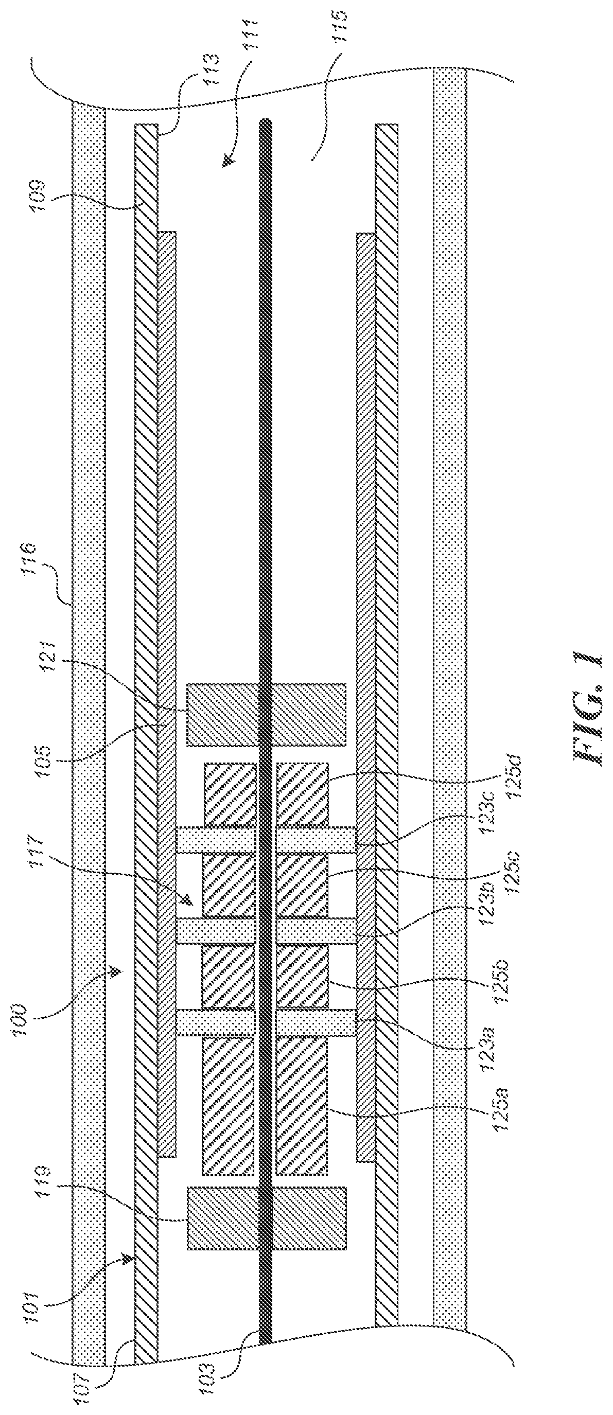
FIG. 1 is a schematic illustration of a medical device delivery system configured in accordance with some embodiments.
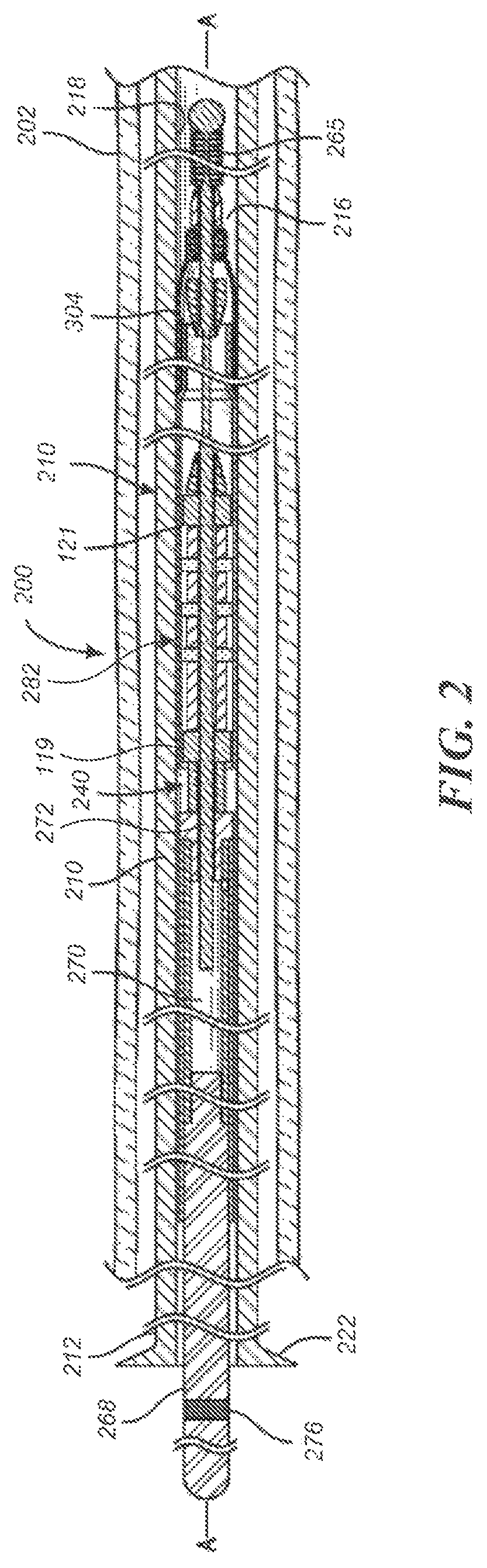
FIG. 2 is a side, cross-sectional view of a medical device delivery system disposed within a body lumen, according to some embodiments.
FIG. 3 is a side, cross-sectional view of a core assembly of the medical device delivery system shown in FIG. 2, according to some embodiments.
FIG. 4 is an enlarged side, cross-sectional view of the delivery system shown in FIG. 2.
FIG. 5A is an enlarged perspective view of a coupling unit having couplers in accordance with some embodiments.
FIG. 5B is an enlarged perspective view of the coupling unit of FIG. 5A with an overlying stent.
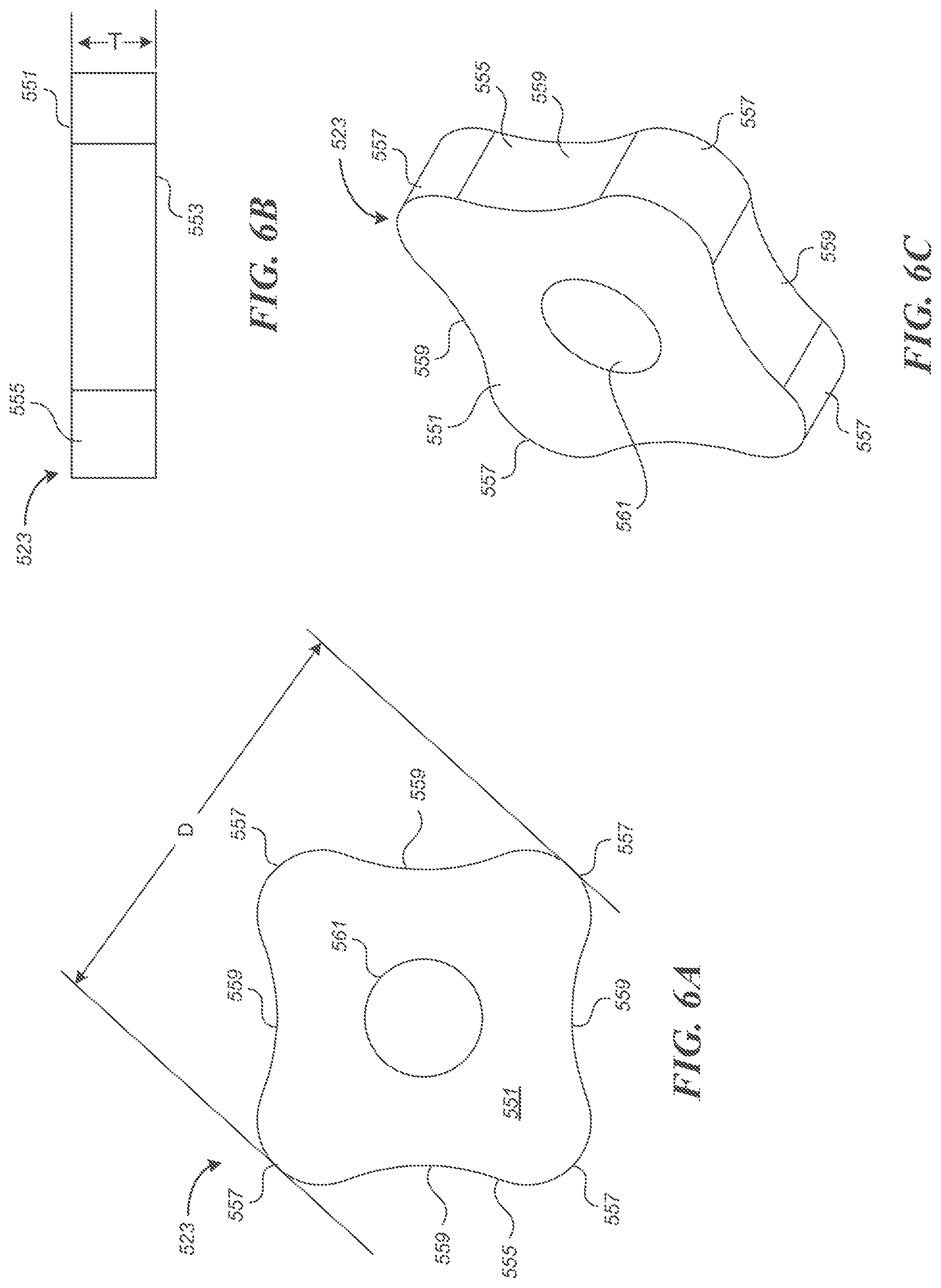
FIGS. 6A-6C are side, end, and perspective views, respectively, of an individual coupler of the coupling unit of FIGS. 5A and 5B.
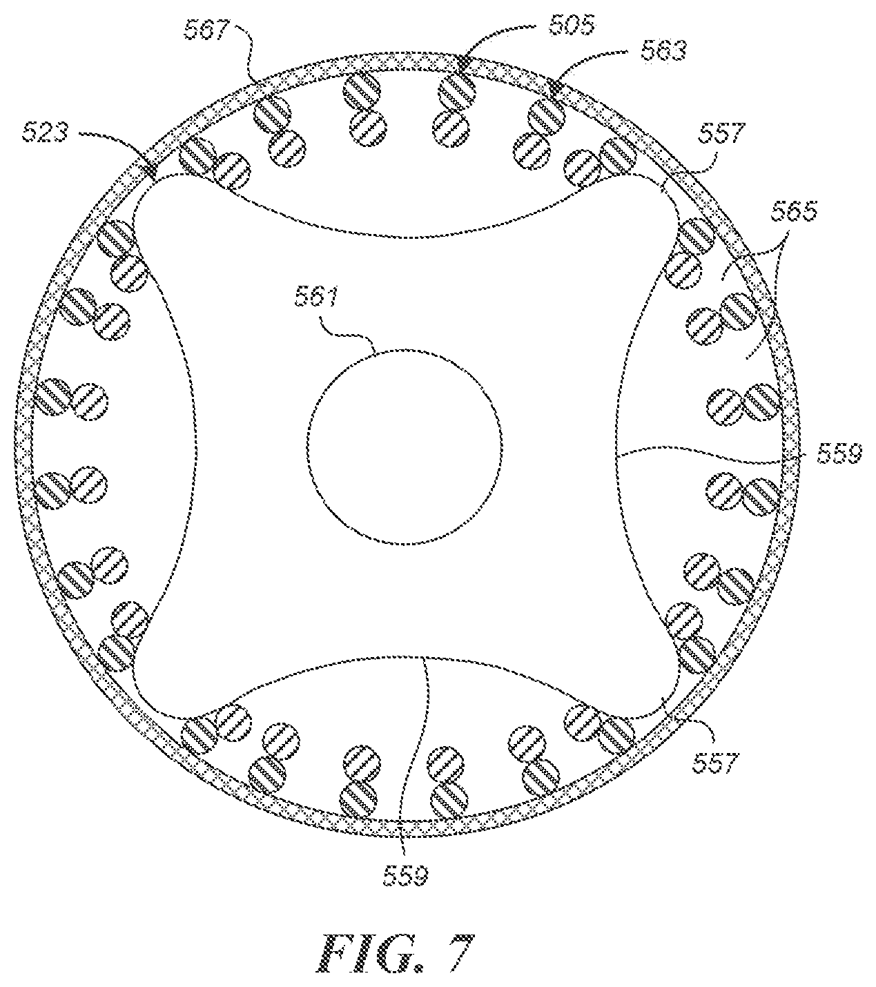
FIG. 7 is a schematic cross-sectional view of a coupler and the stent of FIG. 5B.
DETAILED DESCRIPTION
Conventional stent couplers include soft "pads" that rely on friction fit to secure a stent (such as a braided, knit or woven stent) against an inner wall of a catheter. Such friction-fit pads may require several different pad diameters to accommodate different stent wire size mixes. That is, within a given catheter size, the internal diameter of the compressed (braided, knit or woven) stent contained in the catheter will vary based on the sizes (diameters) of the wires, and possibly other parameters of the stent corresponding to different deployed sizes or target vessel sizes. This can require using different pad diameters to accommodate different stent sizes within a desired range (e.g. about 3.5 to 5 millimeters in diameter), which necessitates manufacturing the pads of various diameters to very small size tolerances. Embodiments of the present technology can allow a single size coupler to be used with a relatively broad range of stent inner diameters within a given catheter size (e.g. a 0.027'', 0.021'', or 0.017'' inner diameter catheter). For example, a coupler comprising a rigid plate that has a plurality of projections separated by recesses can be used to secure a range of different stent sizes within a given catheter.
Specific details of several embodiments of the present technology are described herein with reference to FIGS. 1-7. Although many of the embodiments are described with respect to devices, systems, and methods for delivery of stents and other medical devices, other applications and other embodiments in addition to those described herein are within the scope of the present technology. It should be noted that other embodiments in addition to those disclosed herein are within the scope of the present technology. Further, embodiments of the present technology can have different configurations, components, and/or procedures than those shown or described herein. Moreover, embodiments of the present technology can have configurations, components, and/or procedures in addition to those shown or described herein and that these and other embodiments may not have several of the configurations, components, and/or procedures shown or described herein without deviating from the present technology.
As used herein, the terms "distal" and "proximal" define a position or direction with respect to a clinician or a clinician's control device (e.g., a handle of a delivery catheter). For example, the terms, "distal" and "distally" refer to a position distant from or in a direction away from a clinician or a clinician's control device along the length of device. In a related example, the terms "proximal" and "proximally" refer to a position near or in a direction toward a clinician or a clinician's control device along the length of device. The headings provided herein are for convenience only and should not be construed as limiting the subject matter disclosed.
Selected Examples of Couplers for Medical Device Delivery Systems
FIGS. 1-7 depict embodiments of medical device delivery systems that may be used to deliver and/or deploy a medical device, such as but not limited to a stent, into a hollow anatomical structure such as a blood vessel. The stent can comprise a braided stent or other form of stent such as a woven stent, knit stent, laser-cut stent, roll-up stent, etc. The stent can optionally be configured to act as a "flow diverter" device for treatment of aneurysms, such as those found in blood vessels including arteries in the brain or within the cranium, or in other locations in the body such as peripheral arteries. The stent can optionally be similar to any of the versions or sizes of the PIPELINE.TM. Embolization Device marketed by Medtronic Neurovascular of Irvine, Calif. USA. The stent can alternatively comprise any suitable tubular medical device and/or other features, as described herein.
FIG. 1 is a schematic illustration of a medical device delivery system 100 configured in accordance with an embodiment of the present technology. The system 100 can comprise an elongate tube or catheter 101 which slidably receives a core member 103 configured to carry a stent 105 through the catheter 101. The depicted catheter 101 has a proximal region 107 and an opposing distal region 109 which can be positioned at a treatment site within a patient, an internal lumen 111 extending from the proximal region 107 to the distal region 109, and an inner surface 113 defining the lumen 111. At the distal region 109, the catheter 101 has a distal opening 115 through which the core member 103 may be advanced beyond the distal region 109 to expand or deploy the stent 105 within the blood vessel 116. The proximal region 107 may include a catheter hub (not shown). The catheter 101 can define a generally longitudinal dimension extending between the proximal region 107 and the distal region 109. When the delivery system 100 is in use, the longitudinal dimension need not be straight along some or any of its length.
The core member 103 is configured to extend generally longitudinally through the lumen 111 of the catheter 101. The core member 103 can generally comprise any member(s) with sufficient flexibility and column strength to move the stent 105 or other medical device through the catheter 101. The core member 103 can therefore comprise a wire, tube (e.g., hypotube), braid, coil, or other suitable member(s), or a combination of wire(s), tube(s), braid(s), coil(s), etc.
The system 100 can also include a coupling unit 117 (e.g., a device interface) configured to releasably retain the medical device or stent 105 with respect to the core member 103. The coupling unit 117 is configured to underlie and engage an inner wall of the stent 105. In this manner, the coupling unit 117 cooperates with the overlying inner surface 113 of the catheter 101 to grip the stent 105 such that the coupling unit 117 can move the stent 105 along and within the catheter 101, e.g., distal and/or proximal movement of the core member 103 relative to the catheter 101 results in a corresponding distal and/or proximal movement of the stent 105 within the catheter lumen 111.
The coupling unit 117 can, in some embodiments, be configured to rotate about the core member 103. In some such embodiments, the coupling unit 117 can comprise a proximal restraint 119 and a distal restraint 121. The proximal and distal restraints 119, 121 can be fixed to the core member 103 to prevent or limit proximal or distal movement of the coupling unit 117 along the longitudinal dimension of the core member 103. One or both of the proximal and distal restraints 119, 121 can have an outside diameter or other radially outermost dimension that is smaller than the outside diameter or other radially outermost dimension of the coupling unit 117 such that one or both of the restraints 119, 121 do not contact the inner surface of the stent 105.
The coupling unit 117 can also include one or more couplers 123a-c (e.g., stent engagement members) disposed about the core member 103 and between the proximal and distal restraints 119, 121 and spacer(s) 125a-d. In the illustrated embodiment, the couplers 123a-c are spaced apart from each other by spacers 125b-c, the coupler 123a is spaced apart from the proximal restraint 119 by spacer 125a, and the coupler 123c is spaced apart from the distal restraint by spacer 125d (which can be omitted in some embodiments of the coupling unit 117). One, some or all of the couplers 123a-c can be a rigid plate with a central aperture configured to receive the core member 103 therethrough. The couplers 123a-c are configured to mechanically engage the stent 105 such that the couplers 123a-c retain the stent 105 from moving longitudinally with respect to the core member 103. The spacers 125a-d can each be a substantially cylindrical body with an aperture configured to receive the core member 103 therethrough. One or all of the spacers 125a-d can have an outside diameter or other radially outermost dimension that is smaller than the outside diameter or other radially outermost dimension of the couplers 123a-c so the spacers 125a-d do not contact the inner surface of the stent 105.
Although the embodiment illustrated in FIG. 1 includes three couplers 123a-c and four spacers 125a-d, the number of couplers and spacers can vary. In at least one embodiment, the coupling unit 117 includes only a single coupler without any spacers. In other embodiments, the number of couplers can vary, for example two, three, four, five, six, or more couplers separated by spacers.
In operation, the stent 105 can be moved distally or proximally within the catheter 101 via the core member 103 and the coupling unit 117. To move the stent 105 out of the catheter 101, either the core member 103 is moved distally while the catheter 101 is held stationary or the core member 103 is held stationary while the catheter 101 is withdrawn proximally. When the core member 103 is moved distally and the catheter 101 is held stationary, the proximal restraint 119 bears against the proximal-most spacer 125a and causes the spacers 125a-d and the couplers 123a-c to be advanced distally. The mechanical engagement between the couplers 123a-c and the stent 105 causes the stent 105 to move distally with the couplers 123a-c to deploy the stent 105 out of the distal region 109 of the catheter 101. Conversely, to recapture or otherwise move the stent 105 into the catheter 101, the relative movement between the core member 103 and the catheter 101 is reversed compared moving the stent 105 out of the catheter such that the proximal region of the distal restraint 121 bears against the distal region of the distal-most spacer 125d and thereby causes the spacers 125a-d and the couplers 123a-c to be retracted relative to the catheter 101. The mechanical engagement between the couplers 123a-c and the stent 105 accordingly holds the stent 105 with respect to the core member 103 such that proximal movement of the stent 105 relative to the catheter 101 enables re-sheathing of the stent 105 back into the distal region 109 of the catheter 101. This is useful when the stent 105 has been partially deployed and a portion of the stent remains disposed between at least one of the couplers 123a-c (e.g. the proximal-most coupler 123a) and the inner surface 113 of the catheter 101 because the stent 105 can be withdrawn back into the distal opening 115 of the catheter 101 by moving the core member 103 proximally relative to the catheter 101 (and/or moving the catheter 101 distally relative to the core member 103). Re-sheathing in this manner remains possible until the couplers 123a-c and/or catheter 101 have been moved to a point where the proximal-most coupler 123a is beyond the distal opening 115 of the catheter 101 and the stent 105 is released from between the member 123a and the catheter 101.
The couplers 123a-c and the spacers 125a-d can be fixed to the core member 103 so as to be immovable relative to the core member 103, either in a longitudinal/sliding manner or a radial/rotational manner. Alternatively, the spacers 125a-d and/or the couplers 123a-c can be coupled to (e.g., mounted on) the core member 103 so that the spacers 125a-d and/or the couplers 123a-c can rotate about the longitudinal axis of the core member 103, and/or move or slide longitudinally along the core member 103. In such embodiments, the spacers 125a-d and/or the couplers 123a-c can each have an inner lumen or aperture that receives the core member 103 therein such that the spacers 125a-d and/or the couplers 123a-c can slide and/or rotate relative to the core member 103. Additionally in such embodiments, the proximal and distal restraints 119, 121 can be spaced apart along the core member 103 by a longitudinal distance that is slightly greater than the combined length of the spacers 125a-d and the couplers 123a-c, so as to leave one or more longitudinal gaps between the proximal-most and distal-most spacers 125a, 125d, respectively, and the proximal and distal restraints 119, 121. When present, the longitudinal gap(s) allow the spacers 125a-d and the couplers 123a-c to slide longitudinally along the core member 103 between the restraints 119, 121. The longitudinal range of motion of the spacers 125a-d and the couplers 123a-c between the restraints 119, 121 is approximately equal to the total combined length of the longitudinal gap(s).
Instead of or in addition to the longitudinal gap(s), the coupling unit 117 can include radial gaps between the outer surface of the core member 103 and the inner surface of the spacers 125a-d and the couplers 123a-c. Such radial gaps can be formed when the spacers 125a-d and/or the couplers 123a-c are constructed with holes that are somewhat larger than the outer diameter of the corresponding portion of the core member 103. When present, the radial gaps allow the spacers 125a-d and/or the couplers 123a-c to rotate about the longitudinal axis of the core member 103 between the restraints 119, 121. The presence of longitudinal gaps of at least a minimal size on either side of the spacers 125a-d and the couplers 123a-c can also facilitate the rotatability of the spacers 125a-d and the couplers 123a-c.
FIGS. 2-4 illustrate another embodiment of a medical device delivery system configured in accordance with an embodiment of the present technology. As shown in FIG. 2, the depicted medical device delivery system 200 can comprise an elongate tube or catheter 210 which slidably receives a core assembly 240 configured to carry the stent 201 through the catheter 210. FIG. 3 illustrates the core assembly 240 without depicting the catheter 210 and blood vessel 202 for clarity. The depicted catheter 210 (see FIGS. 2 and 4) has a proximal region 212 and an opposing distal region 214 which can be positioned at a treatment site within a patient, an internal lumen 216 extending from the proximal region 212 to the distal region 214, and an inner surface 218 facing the lumen 216. At the distal region 214, the catheter 210 has a distal opening (not shown) through which the core assembly 240 may be advanced beyond the distal region 214 to expand or deploy the stent 201 within the blood vessel 202. The proximal region 212 may include a catheter hub 222. The catheter 210 can define a generally longitudinal dimension A-A extending between the proximal region 212 and the distal region 214. When the delivery system 200 is in use, the longitudinal dimension need not be straight along some or any of its length.
The catheter 101/210 can optionally comprise a microcatheter. For example, the catheter 101/210 can optionally comprise any of the various lengths of the MARKSMAN.TM. catheter available from Medtronic Neurovascular of Irvine, Calif. USA. The catheter 101/210 can optionally comprise a microcatheter having an inner diameter of about 0.030 inches or less, and/or an outer diameter of 3 French or less near the distal region 109/214. Instead of or in addition to these specifications, the catheter 101/210 can comprise a microcatheter which is configured to percutaneously access the internal carotid artery, or another location within the neurovasculature distal of the internal carotid artery, with its distal opening 113.
The core assembly 240 can comprise a core member 260 configured to extend generally longitudinally through the lumen 216 of the catheter 210. The core member 260 can have a proximal region or section 262 and a terminal or distal region 264, which can optionally include a tip coil 265. The core member 260 can also comprise an intermediate portion 266 located between the proximal region 262 and the distal region 264, which intermediate portion is the portion of the core member 260 onto or over which the stent 201 is positioned or fitted or extends when the core assembly 240 is in the pre-deployment configuration as shown in FIGS. 2-4.
The core member 260 can generally comprise any member(s) with sufficient flexibility and column strength to move the stent 201 or other medical device through the catheter 210. The core member 260 can therefore comprise a wire, tube (e.g., hypotube), braid, coil, or other suitable member(s), or a combination of wire(s), tube(s), braid(s), coil(s), etc. The embodiment of the core member 260 depicted in FIGS. 2-4 is of multi-member construction, comprising a proximal wire 268, a tube 270 (e.g., a hypotube) connected at its proximal region to a distal region of the proximal wire 268, and a distal wire 272 connected at its proximal region to a distal region of the tube 270. An outer layer 274, which can comprise a layer of lubricious material such as PTFE (polytetrafluoroethylene or TEFLON.TM.) or other lubricious polymers, can cover some or all of the tube 270 and/or proximal wire 268. The proximal and/or distal wires 268, 272 may taper or vary in diameter along some or all of their lengths. The proximal wire 268 may include one or more fluorosafe markers 276, and such marker(s) can be located on a portion of the wire 268 that is not covered by the outer layer 274 (e.g., proximal of the outer layer 274). This portion of the wire 268 marked by the marker(s) 276, and/or proximal of any outer layer 274, can comprise a bare metal outer surface.
The core assembly 240 can further comprise a proximal coupling unit 282 and/or a distal coupling unit 290 that can interconnect the medical device or stent 201 with the core member 260. The proximal coupling unit 282 can comprise one or more couplers 123a-c that are configured to underlie the stent 201 and engage an inner wall of the stent. In this manner, the proximal coupling unit 282 cooperates with the overlying inner surface 218 of the catheter 210 to grip the stent 201 such that the proximal coupling unit 282 can move the stent 201 along and within the catheter 210, e.g., as the user pushes the core member 260 distally and/or pulls the core member proximally relative to the catheter 210, resulting in a corresponding distal and/or proximal movement of the stent 201 within the catheter lumen 216.
The proximal coupling unit 282 can, in some embodiments, be similar to any of the versions or embodiments of the coupling unit 117 described above with respect to FIG. 1. For example, the proximal coupling unit 282 can include proximal and distal restraints 119, 121 that are fixed to the core member 260 (e.g., to the distal wire 272 thereof in the depicted embodiment) so as to be immovable relative to the core member 260, either in a longitudinal/sliding manner or a radial/rotational manner. The proximal coupling unit 282 can also include a plurality of couplers 123a-c separated by spacers 125a-d. The couplers 123a-c and spacers 125a-d can be coupled to (e.g., mounted on) the core member 260 so that the proximal coupling unit 282 can rotate about the longitudinal axis A-A of the core member 260 (e.g., of the distal wire 272), and/or move or slide longitudinally along the core member. One or both of the proximal and distal restraints 119, 121 can have an outside diameter or other radially outermost dimension that is smaller than the outside diameter or other radially outermost dimension of the proximal coupling unit 282, so that one or both of the restraints 119, 121 will tend not to contact the inner surface of the stent 201 during operation of the core assembly 240.
In the proximal coupling unit 282 shown in FIGS. 2-4, the stent 201 can be moved distally or proximally within the catheter 210 via the proximal coupling unit 282 and in some embodiments the stent 201 can be resheathed via the proximal coupling unit 282 after partial deployment from the distal opening of the catheter 210, in a manner similar to that described above with respect to the coupling unit 117 in FIG. 1.
Optionally, the proximal edge of the proximal coupling unit 282 can be positioned just distal of the proximal edge of the stent 201 when in the delivery configuration shown in FIGS. 2-4. In some such embodiments, this enables the stent 201 to be re-sheathed when as little as a few millimeters of the stent remains in the catheter 210. Therefore, with stents 201 of typical length, resheathability of 75% or more can be provided (i.e. the stent 201 can be re-sheathed when 75% or more of it has been deployed).
The distal coupling unit 290 can comprise a distal engagement member 292 that can take the form of, for example, a distal device cover or distal stent cover (generically, a "distal cover"). The distal cover 292 can be configured to reduce friction between the medical device or stent 201 (e.g., the distal portion or distal region thereof) and the inner surface 218 of the catheter 210. For example, the distal cover 292 can be configured as a lubricious, flexible structure having a free first end or section 292a that can extend over at least a portion of the stent 201 and/or intermediate portion 266 of the core member 260, and a fixed second end or section 292b that can be coupled (directly or indirectly) to the core member 260.
The distal cover 292 can have a first or delivery position, configuration, or orientation in which the distal cover can extend proximally relative to the distal tip 264, or proximally from the second section 292b or its (direct or indirect) attachment to the core member 260, and at least partially surround or cover a distal portion of the stent 201. The distal cover 292 can be movable from the first or delivery orientation to a second or resheathing position, configuration, or orientation (not shown) in which the distal cover can be everted such that the first end 292a of the distal cover is positioned distally relative to the second end 292b of the distal cover 292 to enable the resheathing of the core assembly 240, either with the stent 201 carried thereby, or without the stent.
The distal cover 292, particularly the first end 292a thereof, can comprise one or more flexible, generally longitudinally extending strips, wings, or elongate portions that are coupled to or integrally formed with the second end 292b. The distal cover 292 can be manufactured or otherwise cut from a tube of the material selected for the distal cover or from multiple radial portions of such a tube. In such embodiments the first section 292a may be formed as multiple longitudinal strips cut from the tube, and the second section 292b may be an uncut (or similarly cut) length of the tube. Accordingly, the second section 292b and the proximally extending strips of the first section 292a may form a single, integral device or structure. In some embodiments, the distal cover 292 comprises only one, or no more than two strips, wings, or elongate portions.
In some embodiments, the distal cover 292 may comprise a tube or a longitudinally slit tube, and the first section 292a can include two or more semi-cylindrical or partially cylindrical strips or tube portions separated by a corresponding number of generally parallel, longitudinally oriented cuts or separations formed or otherwise positioned in the sidewall of the tube. Therefore, when in the pre-expansion state, as shown in FIGS. 2-4, the first section 292a may generally have the shape of a longitudinally split or longitudinally slotted tube extending or interposed radially between the outer surface of the stent or device 200 and the inner surface 218 of the catheter 210.
In various embodiments, the strips, wings, or elongate portions of the first section 292a may collectively span substantially the entire circumference of the outer surface of the stent 201 (e.g., where the cuts between the strips are splits of substantially zero width), or be sized somewhat less than the entire circumference (e.g., where the cuts between the strips are slots having a nonzero width). In accordance with some embodiments, the width of the strips, wings, or elongate portions of the first section 292a can be between about 0.5 mm and about 4 mm. The width can be about 0.5 mm to about 1.5 mm. In accordance with some embodiments, the width can be about 1 mm.
The strips, wings, or elongate portions of the first section 292a can also extend longitudinally over at least a portion of the distal portion of the stent 201. In various embodiments, the first section 292a can extend between about 1 mm and about 3 mm, or between about 1.5 mm and about 2.5 mm, or about 2 mm, over the distal portion of the stent.
The first section 292a and the second section 292b can define a total length of the distal cover 292. In some embodiments, the total length can be between about 4 mm and about 10 mm. The total length can also be between about 5.5 mm and about 8.5 mm. In some embodiments, the total length can be about 7 mm.
The strips of the first section 292a may be of substantially uniform size. For example, the first section 292a can comprise two strips spanning approximately 180 degrees each, three strips spanning approximately 120 degrees each, four strips spanning approximately 90 degrees each, or otherwise be divided to collectively cover all or part of the circumference of the stent, etc. Alternatively, the strips may differ in angular sizing and coverage area without departing from the scope of the disclosure. In one embodiment, only two strips or tube portions are employed in the first section 292a. The use of only two strips can facilitate radial expansion, distal movement and/or fold-over or everting of the first section 192a, as discussed herein, while minimizing the number of free or uncontained strips in the blood vessel lumen and any potential for injuring the vessel by virtue of contact between a strip and the vessel wall.
The distal cover 292 can be manufactured using a lubricious and/or hydrophilic material such as PTFE or Teflon.RTM., but may be made from other suitable lubricious materials or lubricious polymers. The distal cover can also comprise a radiopaque material which can be blended into the main material (e.g., PTFE) to impart radiopacity. The distal cover 292 can have a thickness of between about 0.0005'' and about 0.003''. In some embodiments, the distal cover can be one or more strips of PTFE having a thickness of about 0.001''.
The distal cover 292 (e.g., the second end 292b thereof) can be fixed to the core member 260 (e.g., to the distal wire 272 or distal tip 264 thereof) so as to be immovable relative to the core member 260, either in a longitudinal/sliding manner or a radial/rotational manner. Alternatively, as depicted in FIGS. 2-4, the distal cover 292 (e.g., the second end 292b thereof) can be coupled to (e.g., mounted on) the core member 260 so that the distal cover 292 can rotate about the longitudinal axis A-A of the core member 260 (e.g., of the distal wire 272), and/or move or slide longitudinally along the core member. In such embodiments, the second end 292b can have an inner lumen that receives the core member 260 therein such that the distal cover 292 can slide and/or rotate relative to the core member 260. Additionally in such embodiments, the distal coupling unit 290 can further comprise a proximal restraint 294 that is fixed to the core member 260 and located proximal of the (second end 292b of the) distal cover 292, and/or a distal restraint 296 that is fixed to the core member 260 and located distal of the (second end 292b of the) distal cover 292. The proximal and distal restraints 294, 296 can be spaced apart along the core member 260 by a longitudinal distance that is slightly greater than the length of the second end 292b, so as to leave one or more longitudinal gaps 297 between the second end 292b and one or both of the proximal and distal restraints 194, 196, depending on the position of the second end 292b between the restraints. When present, the longitudinal gap(s) 197 allow the second end 292b and/or distal cover 292 to slide longitudinally along the core member 260 between the restraints 294, 296. The longitudinal range of motion of the second end 292b and/or distal cover 292 between the restraints 294, 296 is approximately equal to the total length of the longitudinal gap(s) 297.
Instead of or in addition to the longitudinal gap(s) 297, the distal coupling unit 290 can comprise a radial gap 298 between the outer surface of the core member 260 (e.g., of the distal wire 272) and the inner surface of the second end 292b. Such a radial gap 298 can be formed when the second end 292b is constructed with an inner luminal diameter that is somewhat larger than the outer diameter of the corresponding portion of the core member 260. When present, the radial gap 298 allows the distal cover 292 and/or second end 292b to rotate about the longitudinal axis A-A of the core member 260 between the restraints 294, 296. The presence of longitudinal gaps 297 of at least a minimal size on either side of the second end 292b can also facilitate the rotatability of the distal cover.
One or both of the proximal and distal restraints 294, 296 can have an outside diameter or other radially outermost dimension that is smaller than the (e.g., pre-deployment) outside diameter or other radially outermost dimension of the distal cover 292, so that one or both of the restraints 294, 296 will tend not to bear against or contact the inner surface 218 of the catheter 210 during operation of the core assembly 240.
In the embodiment depicted in FIGS. 2-4, the second end 292b of the distal cover 292 includes an internal hoop 292c which can comprise a (metallic or polymeric) coil as depicted, or other generally rigid, tubular, or cylindrical internal member such as a short segment of relatively stiff polymeric or metallic tubing. The internal hoop 292c can be contained in an annular enclosure or loop(s) formed by the second end 292b, or otherwise attached to or integrated into the second end 292b in a manner that tends to maintain an inside diameter of the distal cover 292 in the second end 292b that is larger than the outside diameter of the adjacent portion of the core member 160 (or the wire 172 thereof). In other words, the hoop 292c can help maintain the presence of the radial gap 298 between the inside diameter of the second end 292b and the outside diameter of the core member 260 or distal wire 272.
The annular enclosure or loop(s) of the second end 292b can be formed by wrapping a portion of a sheet or tube of the distal cover material (e.g., PTFE) around the sidewall and through the lumen of the hoop 292c and adhering, gluing or heat bonding an end of the wrapped portion of the sheet or tube to the adjacent, proximally extending portion of the sheet or tube. Thus are formed two layers that are adhered together on the proximal side of the hoop 292c. Where the distal cover material comprises PTFE, unsintered PTFE can be used to enable bonding the two portions of the material together with heat and pressure, which is not typically possible with "ordinary" or sintered PTFE.
In operation, the distal cover 292, and in particular the first section 192a, can generally cover and protect the distal region 304 of the stent 201 as the stent 201 is moved distally within the catheter 110. The distal cover 192 may serve as a bearing or buffer layer that, for example, inhibits filament ends of the distal region 304 of the stent 201 (where the stent 201 comprises a braided stent) from contacting the inner surface 118 of the catheter 110, which could damage the stent 201 and/or catheter 110, or otherwise compromise the structural integrity of the stent 201. Since the distal cover 192 may be made of a lubricious material, the distal cover 192 may exhibit a low coefficient of friction that allows the distal region 304 of the stent 201 to slide axially within the catheter 110 with relative ease. The coefficient of friction between the distal cover and the inner surface of the catheter can be between about 0.02 and about 0.4. For example, in embodiments in which the distal cover and the catheter are formed from PTFE, the coefficient of friction can be about 0.04. Such embodiments can advantageously improve the ability of the core assembly to pass through the catheter, especially in tortuous vasculature.
Further, as shown in FIGS. 2-4, at least a portion of the distal cover 292 can at least partially extend or be interposed radially between the distal portion of the stent 201 and the inner surface 218 of the catheter 210 in the first position, configuration, or orientation. In the first orientation, the first section 292a of the distal cover 292 can extend from the second section 292b in a proximal direction to a point where the first section is interposed between the distal portion of the stent 201 and the inner surface 218 of the catheter 210. In this orientation, the first section of the distal cover can take on a "proximally oriented" position or configuration.
Structures other than the herein-described embodiments of the distal cover 292 may be used in the core assembly 240 and/or distal coupling unit 290 to cover or otherwise interface with the distal region 304 of the stent 201. For example, a protective coil or other sleeve having a longitudinally oriented, proximally open lumen may be employed. In other embodiments, the distal coupling unit 290 can omit the distal cover 292, or the distal cover can be replaced with a component similar to the proximal coupling unit 282. Where the distal cover 292 is employed, it can be connected to the distal tip coil 265 (e.g., by being wrapped around and enclosing some or all of the winds of the coil 265) or being adhered to or coupled to the outer surface of the coil by an adhesive or a surrounding shrink tube. The distal cover 292 can be coupled (directly or indirectly) to other portions of the core assembly 240, such as the distal wire 272.
In embodiments of the core assembly 240 that employ both a rotatable proximal coupling unit 282 and a rotatable distal cover 292, the stent 201 can be rotatable with respect to the core member 260 about the longitudinal axis A-A thereof, by virtue of the rotatable (connections of the) proximal coupling unit 282 and distal cover 292. In such embodiments, the stent 201, proximal coupling unit 282 and distal cover 292 can rotate together in this manner about the core member. When the stent 201 can rotate about the core member 260, the core assembly 240 can be advanced more easily through tortuous vessels as the tendency of the vessels to twist the stent and/or core assembly is negated by the rotation of the stent, proximal engagement member and distal cover about the core member. In addition, the required push force or delivery force is reduced, as the user's input push force is not diverted into torsion of the stent and/or core member. The tendency of a twisted stent and/or core member to untwist suddenly or "whip" upon exiting tortuosity or deployment of the stent, and the tendency of a twisted stent to resist expansion upon deployment, are also reduced or eliminated. Further, in some such embodiments of the core assembly 240, the user can "steer" the core assembly 240 via the tip coil 265, particularly if the coil 265 is bent at an angle in its unstressed configuration. Such a coil tip can be rotated about the axis A-A relative to the stent 201, coupling unit 282 and/or distal cover 292 by rotating the distal region 264 of the core member 260. Thus the user can point the coil tip in the desired direction of travel of the core assembly, and upon advancement of the core assembly the tip will guide the core assembly in the chosen direction.
FIG. 5A is an enlarged perspective view of a coupling unit 517 of a medical device delivery system 500. FIG. 5B illustrates the coupling unit 517 with an overlying stent 505. The coupling unit 517 includes a plurality of couplers 523a-c separated by a plurality of spacers 525a-d. A proximal restraint 519 is disposed proximally to the proximal-most spacer 525a. The proximal restraint 519 and the coupling unit 517 are disposed around the core member 503. FIGS. 6A-6C are side, end, and perspective views, respectively, of a coupler 523 of the coupling unit 517 shown in FIGS. 5A and 5B. FIG. 7 is a schematic cross-sectional view of the coupler 523 engaging the stent 505. The depicted stent 505 is braided (although other types of stent, as disclosed elsewhere herein may be used) and includes a mesh 563 forming a plurality of pores 565 which are separated by points where the wires of the braid cross or intersect.
Referring to FIGS. 5A-7 together, each of the couplers 523 can have a plate-like configuration with first and second end faces 551, 553 and a side surface 555 extending between the first and second end faces 551, 553. In the assembled delivery system 500, the first and second end faces 551, 553 can be oriented and maintained substantially orthogonal to a long axis of the core member 503. This can be achieved by configuring the spacers 525a-d with distal and proximal end faces that are orthogonal to the longitudinal axis of each spacer 525 (and/or to the core member 503), and/or minimizing the amount of longitudinal movement space (or "play") among the couplers and spacers of the coupling unit 517. Each coupler forms a plurality of radially-extending projections 557 separated by recesses 559. In the illustrated embodiment, there are four projections 557 separated by four recesses 559. However, in other embodiments the number of projections can vary, for example two, three, four, five, six, seven, or more projections separated by a corresponding number of recesses.
The projections 557 can include rounded edges and the recesses 559 can include rounded depressions. During use of the delivery system 500, the rounded edges can reduce scraping of the projections 557 against the inner wall of an overlying catheter 567, which reduces generation of particulates and damage to the catheter 567. When the delivery system 500 is used with a braided stent such as the depicted stent 505, the recesses 559 can be sized to accommodate the thickness of braid wire crossings such that each projection can extend at least partially into a pore 565 of the stent 505 between the adjacent wire crossings and the wire crossings surrounding the pore 565 can be at least partially received within the recesses 559 of the coupler. In other embodiments, the projections and/or the recesses can assume other forms, for example with sharper or flatter peaks formed by the projections. The coupler 523 can be manufactured by photochemical etching, laser cutting, molding, machining or other suitable processes.
Each coupler 523 includes an opening or central aperture 561 configured to receive the core member 503 therethrough. As noted previously, the opening of the aperture 561 can be larger than the diameter of the core member 503 such that the couplers 523 can rotate about the long axis of the core member 503.
The couplers 523 can be made to have a relatively thin and/or plate-like configuration. Such a configuration can facilitate the formation of projections 557 that are small enough to fit inside the pores 565 of the stent 505. Accordingly, the couplers 523 may be characterized by a largest diameter D along the first and second end faces 551, 553, and a thickness T measured along the side surface 555. In some embodiments, the diameter D is at least five times greater than the thickness T. In at least one embodiment, the thickness T is between approximately 25-100 microns, or 25-75 microns, for example, approximately 50 microns (approximately 0.002'').
In order to effectively push or pull the stent 505 along the catheter 567, the couplers 523 can be made to be rigid (e.g., incompressible by the forces encountered in typical use of the delivery system). The rigidity of the couplers 523 can be due to their material composition, their shape/construction, or both. In some embodiments, the couplers 523 are made of metal (e.g., stainless steel, Nitinol, etc.) or rigid polymers (e.g., polyimide), or both. In some embodiments, even if the coupler is made of a rigid material, based on structural characteristics the coupler itself may be non-rigid and at least partially compressible.
The spacers 525 can be substantially cylindrical bodies having a smaller outer diameter than a largest outer diameter of the couplers 523. In some embodiments, the spacers 525 include a central aperture (not shown) sized and configured to allow the spacers 525 to be rotatably mounted over the core member 503. As mentioned previously, the spacers 525 can have end walls that are orthogonal to a long axis of the core member 503. These orthogonal end walls can help preserve the orthogonal orientation of the couplers 523 relative to the core member 503 to prevent loss of engagement with stent 505.
In some embodiments, the coupling unit 517 can be configured to engage only a proximal portion (e.g., only a proximal half, only the proximal-most third, etc.) of the stent 505. In other embodiments, coupling unit 517 can engage the stent 505 along substantially its entire length.
The couplers 523 can mechanically interlock with or engage the stent 505 such that each projection 557 is at least partially received within one of the pores 565. The spacers can be configured with a length such that the projections 557 of adjacent couplers 523 (e.g., coupler 523a and adjacent coupler 523b) are spaced apart longitudinally by a distance that is equal to the "pore pitch" of the stent 505 (the distance between the centers of longitudinally adjacent pores 565) or, more typically, a whole-number multiple of the pore pitch of the stent 505, when the stent is at the inner diameter of the catheter 567. Accordingly, each projection can extend into and engage one of the pores 565 of the stent 505. In some embodiments, adjacent couplers 523 can engage longitudinally adjacent pores 565 of the stent 505; in other embodiments adjacent couplers 523 engage pores 565 which are not longitudinally adjacent but are spaced apart longitudinally by one or more intervening pores. Therefore the first and second couplers 523a and 523b can be spaced apart from one another by a longitudinal distance corresponding to the pore pitch of the stent 505, or by a longitudinal distance corresponding to a whole number multiple of the pore pitch.
The interaction between the projections 557 and the pores 565 can produce a mechanical interlock between stent coupler 523 and the pores 565. This is in contrast to a conventional compressible pad that resiliently pushes against the stent as a whole, including the wire crossings. In at least some embodiments, the mechanical interlock provided by the couplers 523 secures the stent 505 without pressing against the wire crossings of the stent 505. In some embodiments, the couplers 523 are configured to secure a range of different stent sizes within a given catheter size (e.g., within a 0.017'', 0.021'' or 0.027'' catheter (inside diameter)).
Note that various components of the delivery system 500 of FIGS. 5A-7 can be incorporated into the delivery system 100 of FIG. 1, or into the delivery system 200 of FIGS. 2-4. For example, any of the disclosed embodiments of the coupling unit 517 can be employed as the coupling unit of the delivery system 100 or of the delivery system 200. Similarly, any of the embodiments of the couplers 523 can be employed as the coupler(s) of the delivery system 100 or of the delivery system 200, and/or any of the embodiments of the spacers 525 can be employed as the spacer(s) of the delivery system 100 or of the delivery system 200.
CONCLUSION
This disclosure is not intended to be exhaustive or to limit the present technology to the precise forms disclosed herein. Although specific embodiments are disclosed herein for illustrative purposes, various equivalent modifications are possible without deviating from the present technology, as those of ordinary skill in the relevant art will recognize. In some cases, well-known structures and functions have not been shown and/or described in detail to avoid unnecessarily obscuring the description of the embodiments of the present technology. Although steps of methods may be presented herein in a particular order, in alternative embodiments the steps may have another suitable order. Similarly, certain aspects of the present technology disclosed in the context of particular embodiments can be combined or eliminated in other embodiments. Furthermore, while advantages associated with certain embodiments may have been disclosed in the context of those embodiments, other embodiments can also exhibit such advantages, and not all embodiments need necessarily exhibit such advantages or other advantages disclosed herein to fall within the scope of the present technology. Accordingly, this disclosure and associated technology can encompass other embodiments not expressly shown and/or described herein.
Throughout this disclosure, the singular terms "a," "an," and "the" include plural referents unless the context clearly indicates otherwise. Similarly, unless the word "or" is expressly limited to mean only a single item exclusive from the other items in reference to a list of two or more items, then the use of "or" in such a list is to be interpreted as including (a) any single item in the list, (b) all of the items in the list, or (c) any combination of the items in the list. Additionally, the terms "comprising" and the like are used throughout this disclosure to mean including at least the recited feature(s) such that any greater number of the same feature(s) and/or one or more additional types of features are not precluded. Directional terms, such as "upper," "lower," "front," "back," "vertical," and "horizontal," may be used herein to express and clarify the relationship between various elements. It should be understood that such terms do not denote absolute orientation. Reference herein to "one embodiment," "an embodiment," or similar formulations means that a particular feature, structure, operation, or characteristic described in connection with the embodiment can be included in at least one embodiment of the present technology. Thus, the appearances of such phrases or formulations herein are not necessarily all referring to the same embodiment. Furthermore, various particular features, structures, operations, or characteristics may be combined in any suitable manner in one or more embodiments.
* * * * *
D00000
D00001
D00002
D00003
D00004
D00005
D00006
D00007
XML
uspto.report is an independent third-party trademark research tool that is not affiliated, endorsed, or sponsored by the United States Patent and Trademark Office (USPTO) or any other governmental organization. The information provided by uspto.report is based on publicly available data at the time of writing and is intended for informational purposes only.
While we strive to provide accurate and up-to-date information, we do not guarantee the accuracy, completeness, reliability, or suitability of the information displayed on this site. The use of this site is at your own risk. Any reliance you place on such information is therefore strictly at your own risk.
All official trademark data, including owner information, should be verified by visiting the official USPTO website at www.uspto.gov. This site is not intended to replace professional legal advice and should not be used as a substitute for consulting with a legal professional who is knowledgeable about trademark law.