Optical imaging lens assembly
Xu , et al. March 9, 2
U.S. patent number 10,942,334 [Application Number 16/227,008] was granted by the patent office on 2021-03-09 for optical imaging lens assembly. This patent grant is currently assigned to Zhejiang Sunny Optical Co., Ltd. The grantee listed for this patent is Zhejiang Sunny Optical Co., Ltd. Invention is credited to Jianke Wenren, Biao Xu, Kaiyuan Zhang.


View All Diagrams
| United States Patent | 10,942,334 |
| Xu , et al. | March 9, 2021 |
Optical imaging lens assembly
Abstract
The present disclosure discloses an optical imaging lens assembly. The optical imaging lens assembly includes, sequentially from an object side to an image side along an optical axis, a first lens, a second lens, a third lens, a fourth lens, a fifth lens, a sixth lens, and a seventh lens. The first lens has a positive refractive power and a convex object-side surface. The second lens has a negative refractive power. The third lens has a positive refractive power. Each of the fourth lens and the fifth lens has a positive refractive power or a negative refractive power. The sixth lens has a positive refractive power. The seventh lens has a negative refractive power, a concave object-side surface and a concave image-side surface. A combined focal length f12 of the first and second lenses and a combined focal length f34 of the third and fourth lenses satisfy: |f12/f34|.ltoreq.0.3.
| Inventors: | Xu; Biao (Ningbo, CN), Zhang; Kaiyuan (Ningbo, CN), Wenren; Jianke (Ningbo, CN) | ||||||||||
|---|---|---|---|---|---|---|---|---|---|---|---|
| Applicant: |
|
||||||||||
| Assignee: | Zhejiang Sunny Optical Co., Ltd
(Ningbo, CN) |
||||||||||
| Family ID: | 1000005410175 | ||||||||||
| Appl. No.: | 16/227,008 | ||||||||||
| Filed: | December 20, 2018 |
Prior Publication Data
| Document Identifier | Publication Date | |
|---|---|---|
| US 20190146184 A1 | May 16, 2019 | |
Related U.S. Patent Documents
| Application Number | Filing Date | Patent Number | Issue Date | ||
|---|---|---|---|---|---|
| PCT/CN2018/095835 | Jul 16, 2018 | ||||
Foreign Application Priority Data
| Oct 26, 2017 [CN] | 201711012647.6 | |||
| Oct 26, 2017 [CN] | 201721402226.X | |||
| Current U.S. Class: | 1/1 |
| Current CPC Class: | H04N 5/2254 (20130101); G02B 27/0025 (20130101); G02B 9/64 (20130101); G02B 13/0045 (20130101) |
| Current International Class: | G02B 27/00 (20060101); H04N 5/225 (20060101); G02B 13/00 (20060101); G02B 9/64 (20060101) |
| Field of Search: | ;359/708,755 |
References Cited [Referenced By]
U.S. Patent Documents
| 9116329 | August 2015 | Fukaya |
| 9638896 | May 2017 | Fukaya |
| 2014/0139719 | May 2014 | Fukaya |
| 2015/0226941 | August 2015 | Fukaya |
| 2016/0124191 | May 2016 | Hashimoto |
| 2016/0341937 | November 2016 | Tsai |
| 2017/0082834 | March 2017 | Tang et al. |
| 2017/0082835 | March 2017 | Tang et al. |
| 2017/0176723 | June 2017 | Fukaya |
| 2018/0188483 | July 2018 | Hsieh et al. |
| 2018/0188499 | July 2018 | Hashimoto |
| 2018/0246299 | August 2018 | Fukaya |
| 2018/0246301 | August 2018 | Fukaya |
| 2018/0267275 | September 2018 | Fukaya |
| 2019/0004285 | January 2019 | Tang |
| 104597582 | May 2015 | CN | |||
| 105445907 | Mar 2016 | CN | |||
| 106950681 | Jul 2017 | CN | |||
| 107621683 | Jan 2018 | CN | |||
| 207301467 | May 2018 | CN | |||
| 2015-225246 | Dec 2015 | JP | |||
Attorney, Agent or Firm: Sughrue Mion, PLLC
Parent Case Text
CROSS-REFERENCE TO RELATED APPLICATIONS
This is a continuation of International Application PCT/CN2018/095835, with an international filing date of Jul. 16, 2018, which claims the priorities and rights to Chinese Patent Application No. 201711012647.6 and Chinese Patent Application No. 201721402226.X filed with the China National Intellectual Property Administration (CNIPA) on Oct. 26, 2017, the disclosures of which are hereby incorporated by reference in their entireties.
Claims
What is claimed is:
1. An optical imaging lens assembly comprising, sequentially from an object side to an image side along an optical axis, a first lens, a second lens, a third lens, a fourth lens, a fifth lens, a sixth lens, and a seventh lens, wherein the first lens has a positive refractive power, an object-side surface of the first lens is a convex surface, and an image-side surface of the first lens is a convex surface; the second lens has a negative refractive power; the third lens has a positive refractive power; each of the fourth lens and the fifth lens has a positive refractive power or a negative refractive power; the sixth lens has a positive refractive power; the seventh lens has a negative refractive power, and an object-side surface and an image-side surface of the seventh lens are concave surfaces; and a combined focal length f12 of the first lens and the second lens and a combined focal length f34 of the third lens and the fourth lens satisfy: |f12/f34|.ltoreq.0.3, wherein an effective focal length f2 of the second lens and an effective focal length f7 of the seventh lens satisfy: 4.5<f2/f7<11.0.
2. The optical imaging lens assembly according to claim 1, wherein a total effective focal length f of the optical imaging lens assembly and an entrance pupil diameter EPD of the optical imaging lens assembly satisfy: f/EPD.ltoreq.1.80.
3. The optical imaging lens assembly according to claim 1, wherein a total effective focal length f of the optical imaging lens assembly and the effective focal length f7 of the seventh lens satisfy: -2.5<f/f7<-1.5.
4. The optical imaging lens assembly according to claim 3, wherein an effective focal length f6 of the sixth lens and the effective focal length f7 of the seventh lens satisfy: -1.5<f6/f7<-1.0.
5. The optical imaging lens assembly according to claim 3, wherein the effective focal length f7 of the seventh lens and a radius of curvature R14 of the image-side surface of the seventh lens satisfy: -1.5<f7/R14<-1.0.
6. The optical imaging lens assembly according to claim 1, wherein an effective focal length f1 of the first lens and a radius of curvature R1 of the object-side surface of the first lens satisfy: 2.0<f1/R1<3.0.
7. The optical imaging lens assembly according to claim 1, wherein a center thickness CT1 of the first lens on the optical axis and the effective focal length f2 of the second lens satisfy: -0.2<CT1/f2<0.
8. The optical imaging lens assembly according to claim 1, wherein an effective focal length f6 of the sixth lens and an effective focal length f3 of the third lens satisfy: 0<f6/f3<0.5.
9. The optical imaging lens assembly according to claim 1, wherein a radius of curvature R1 of the object-side surface of the first lens and a radius of curvature R4 of an image-side surface of the second lens satisfy: 0<R1/R4<1.
10. The optical imaging lens assembly according to claim 1, wherein a radius of curvature R12 of an image-side surface of the sixth lens and a radius of curvature R14 of the image-side surface of the seventh lens satisfy: -1.5<R12/R14<-0.5.
11. The optical imaging lens assembly according to claim 1, wherein a center thickness CT6 of the sixth lens on the optical axis satisfies: 0.3 mm<CT6<0.8 mm.
12. The optical imaging lens assembly according to claim 11, wherein a total track length TTL of the optical imaging lens assembly and half of a diagonal length ImgH of an effective pixel area on an image plane of the optical imaging lens assembly satisfy: TTL/ImgH.ltoreq.1.50.
Description
TECHNICAL FIELD
The present disclosure relates to an optical imaging lens assembly, and more specifically to an optical imaging lens assembly including seven lenses.
BACKGROUND
With the improvement in performance and reduction in size of the commonly used photosensitive elements such as charge-coupled devices (CCD) or complementary metal-oxide semiconductor elements (CMOS), the number of pixels of the photosensitive elements is increased and the size of the pixels is reduced. Accordingly, higher requirements on high imaging quality and miniaturization of the counterpart optical imaging lens assemblies have been brought forward.
The reduction in pixel size means that the amount of light passing through the lens may become less during the same exposure time. However, in the condition of a dim environment (e.g., cloudy and rainy days, or at dusk), the lens assembly needs to have a large amount of light passing through to ensure the imaging quality. A general configuration for an existing lens assembly includes an F-number Fno (total effective focal length of the lens assembly/entrance pupil diameter of the lens assembly) of 2.0 or above. Although this type of lens assembly can fulfill the miniaturization requirement, the imaging quality of the lens assembly cannot be ensured in a situation with insufficient light. Therefore, the lens assembly having the F-number Fno of 2.0 or above can no longer fulfill the higher-order imaging requirements.
SUMMARY
The present disclosure provides an optical imaging lens assembly which may be applicable to portable electronic products and may at least or partially sovle at least one of the above disadvantages in the existing technology, for example, an imaging lens assembly having a large aperture.
According to an aspect, the present disclosure provides an optical imaging lens assembly. The optical imaging lens assembly includes, sequentially from an object side to an image side along an optical axis, a first lens, a second lens, a third lens, a fourth lens, a fifth lens, a sixth lens, and a seventh lens. The first lens may have a positive refractive power, and an object-side surface of the first lens may be a convex surface. The second lens may have a negative refractive power. The third lens may have a positive refractive power. Each of the fourth lens and the fifth lens has a positive refractive power or a negative refractive power. The sixth lens may have a positive refractive power. The seventh lens may have a negative refractive power, and an object-side surface and an image-side surface of the seventh lens may both be concave surfaces. A combined focal length f12 of the first lens and the second lens and a combined focal length f34 of the third lens and the fourth lens may satisfy: |f12/f34|.ltoreq.0.3.
In an embodiment, a total effective focal length f of the optical imaging lens assembly and an entrance pupil diameter EPD of the optical imaging lens assembly may satisfy: f/EPD.ltoreq.1.80.
In an embodiment, the total effective focal length f of the optical imaging lens assembly and an effective focal length f7 of the seventh lens may satisfy: -2.5<f/f7<-1.5.
In an embodiment, an effective focal length f2 of the second lens and the effective focal length f7 of the seventh lens may satisfy: 4.5<f2/f7<11.0.
In an embodiment, an effective focal length f6 of the sixth lens and the effective focal length f7 of the seventh lens may satisfy: -1.5<f6/f7<-1.0.
In an embodiment, the effective focal length f7 of the seventh lens and a radius of curvature R14 of the image-side surface of the seventh lens may satisfy: -1.5<f7/R14<-1.0.
In an embodiment, an effective focal length f1 of the first lens and a radius of curvature R1 of the object-side surface of the first lens may satisfy: 2.0<f1/R1<3.0.
In an embodiment, a center thickness CT1 of the first lens on the optical axis and the effective focal length f2 of the second lens may satisfy: -0.2<CT1/f2<0.
In an embodiment, the effective focal length f6 of the sixth lens and an effective focal length f3 of the third lens may satisfy: 0<f6/f3<0.5.
In an embodiment, the radius of curvature R1 of the object-side surface of the first lens and a radius of curvature R4 of an image-side surface of the second lens may satisfy: 0<R1/R4<1.
In an embodiment, a radius of curvature R12 of an image-side surface of the sixth lens and the radius of curvature R14 of the image-side surface of the seventh lens may satisfy: -1.5<R12/R14<-0.5.
In an embodiment, a center thickness CT6 of the sixth lens on the optical axis may satisfy: 0.3 mm<CT6<0.8 mm.
In an embodiment, a total track length TTL of the optical imaging lens assembly and half of a diagonal length ImgH of an effective pixel area on an image plane of the optical imaging lens assembly may satisfy: TTL/ImgH.ltoreq.1.50.
According to another aspect, the present disclosure provides an optical imaging lens assembly. The optical imaging lens assembly includes, sequentially from an object side to an image side along an optical axis, a first lens, a second lens, a third lens, a fourth lens, a fifth lens, a sixth lens, and a seventh lens. The first lens may have a positive refractive power, an object-side surface of the first lens may be a convex surface, and an image-side surface of the first lens may be a concave surface. The second lens may have a negative refractive power. The third lens may have a positive refractive power. Each of the fourth lens and the fifth lens has a positive refractive power or a negative refractive power. The sixth lens may have a positive refractive power. The seventh lens may have a negative refractive power, and an object-side surface and an image-side surface of the seventh lens may both be concave surfaces. A total track length TTL of the optical imaging lens assembly and half of a diagonal length ImgH of an effective pixel area on an image plane of the optical imaging lens assembly may satisfy: TTL/ImgH.ltoreq.1.50.
The present disclosure adopts a plurality of lenses (e.g., seven lenses). By reasonably distributing the refractive powers and the surface types of the lenses, the center thicknesses of the lenses, the spacing distances on the optical axis between the lenses, etc., the above optical imaging lens assembly has at least one of the beneficial effects such as ultra-thin, miniaturization, large aperture, and high imaging quality.
BRIEF DESCRIPTION OF THE DRAWINGS
By describing non-limiting embodiments below in detail and in combination with the accompanying drawings, other features, objectives and advantages of the present disclosure will be more apparent. In the accompanying drawings:
FIG. 1 is a schematic structural diagram illustrating an optical imaging lens assembly according to Embodiment 1 of the present disclosure;
FIGS. 2A-2D respectively illustrate a longitudinal aberration curve, an astigmatic curve, a distortion curve, and a lateral color curve of the optical imaging lens assembly according to Embodiment 1;
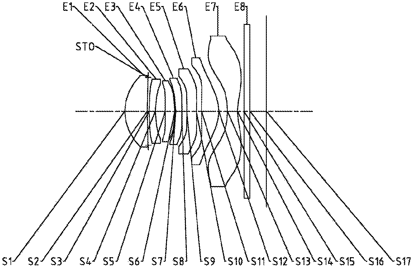
FIG. 3 is a schematic structural diagram illustrating an optical imaging lens assembly according to Embodiment 2 of the present disclosure;
FIGS. 4A-4D respectively illustrate a longitudinal aberration curve, an astigmatic curve, a distortion curve, and a lateral color curve of the optical imaging lens assembly according to Embodiment 2;
FIG. 5 is a schematic structural diagram illustrating an optical imaging lens assembly according to Embodiment 3 of the present disclosure;
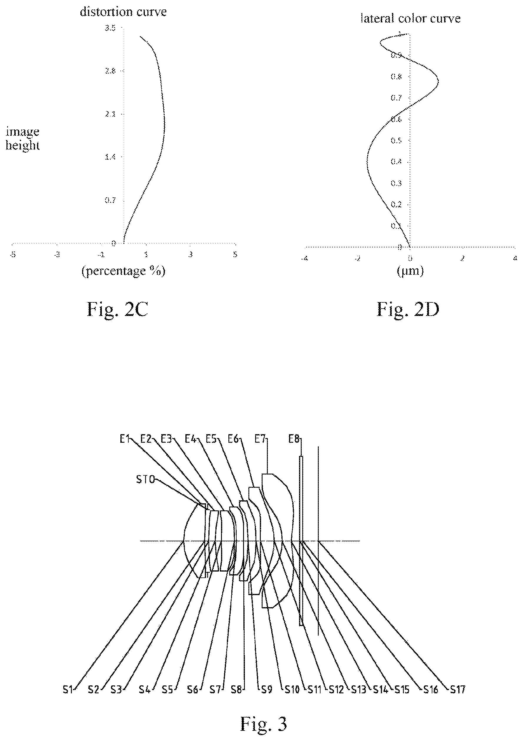
FIGS. 6A-6D respectively illustrate a longitudinal aberration curve, an astigmatic curve, a distortion curve, and a lateral color curve of the optical imaging lens assembly according to Embodiment 3;
FIG. 7 is a schematic structural diagram illustrating an optical imaging lens assembly according to Embodiment 4 of the present disclosure;
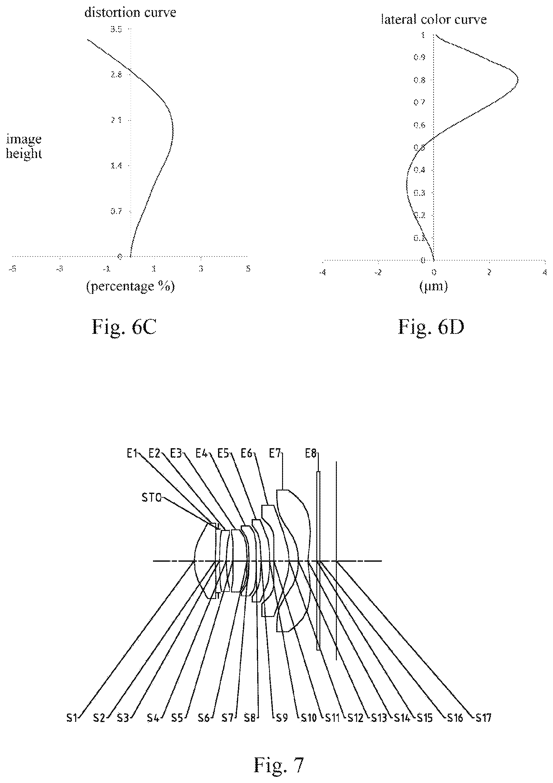
FIGS. 8A-8D respectively illustrate a longitudinal aberration curve, an astigmatic curve, a distortion curve, and a lateral color curve of the optical imaging lens assembly according to Embodiment 4;
FIG. 9 is a schematic structural diagram illustrating an optical imaging lens assembly according to Embodiment 5 of the present disclosure;
FIGS. 10A-10D respectively illustrate a longitudinal aberration curve, an astigmatic curve, a distortion curve, and a lateral color curve of the optical imaging lens assembly according to Embodiment 5;
FIG. 11 is a schematic structural diagram illustrating an optical imaging lens assembly according to Embodiment 6 of the present disclosure;
FIGS. 12A-12D respectively illustrate a longitudinal aberration curve, an astigmatic curve, a distortion curve, and a lateral color curve of the optical imaging lens assembly according to Embodiment 6;
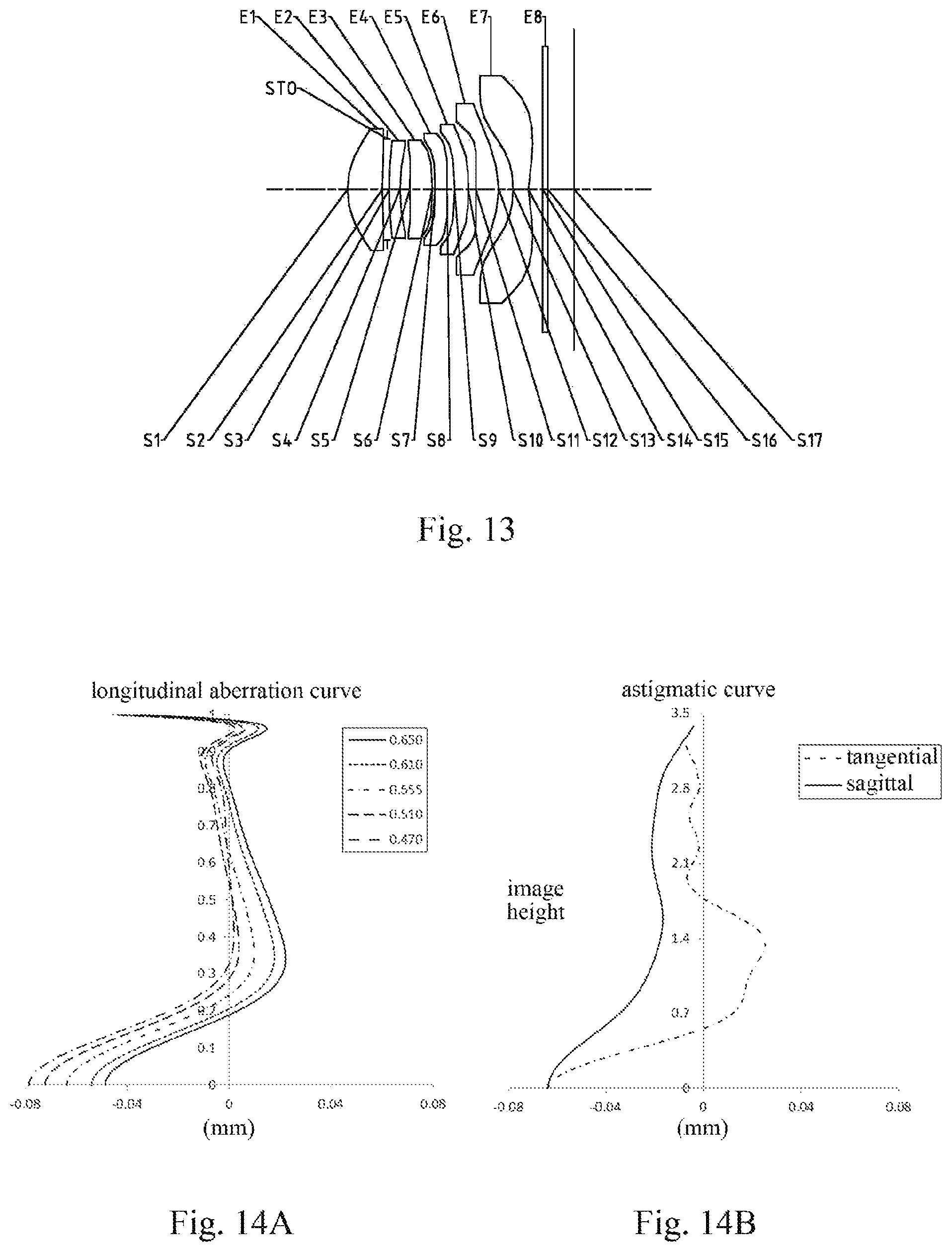
FIG. 13 is a schematic structural diagram illustrating an optical imaging lens assembly according to Embodiment 7 of the present disclosure;
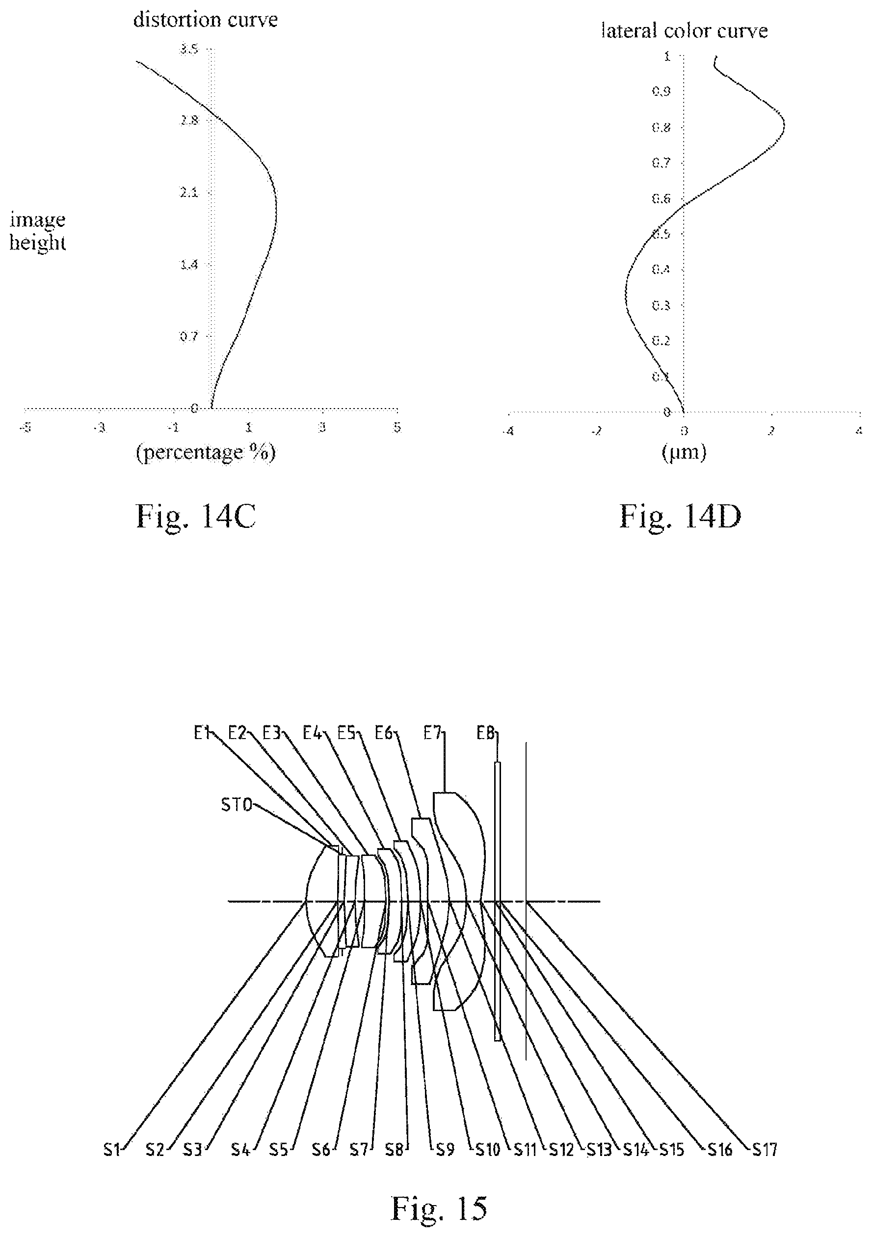
FIGS. 14A-14D respectively illustrate a longitudinal aberration curve, an astigmatic curve, a distortion curve, and a lateral color curve of the optical imaging lens assembly according to Embodiment 7;
FIG. 15 is a schematic structural diagram illustrating an optical imaging lens assembly according to Embodiment 8 of the present disclosure;
FIGS. 16A-16D respectively illustrate a longitudinal aberration curve, an astigmatic curve, a distortion curve, and a lateral color curve of the optical imaging lens assembly according to Embodiment 8;
FIG. 17 is a schematic structural diagram illustrating an optical imaging lens assembly according to Embodiment 9 of the present disclosure;
FIGS. 18A-18D respectively illustrate a longitudinal aberration curve, an astigmatic curve, a distortion curve, and a lateral color curve of the optical imaging lens assembly according to Embodiment 9;
FIG. 19 is a schematic structural diagram illustrating an optical imaging lens assembly according to Embodiment 10 of the present disclosure;
FIGS. 20A-20D respectively illustrate a longitudinal aberration curve, an astigmatic curve, a distortion curve, and a lateral color curve of the optical imaging lens assembly according to Embodiment 10;
FIG. 21 is a schematic structural diagram illustrating an optical imaging lens assembly according to Embodiment 11 of the present disclosure;
FIGS. 22A-22D respectively illustrate a longitudinal aberration curve, an astigmatic curve, a distortion curve, and a lateral color curve of the optical imaging lens assembly according to Embodiment 11;
FIG. 23 is a schematic structural diagram illustrating an optical imaging lens assembly according to Embodiment 12 of the present disclosure; and
FIGS. 24A-24D respectively illustrate a longitudinal aberration curve, an astigmatic curve, a distortion curve, and a lateral color curve of the optical imaging lens assembly according to Embodiment 12.
DETAILED DESCRIPTION
For a better understanding of the present disclosure, various aspects of the present disclosure will be described in more detail with reference to the accompanying drawings. It should be understood that the detailed description is merely an illustration for the exemplary embodiments of the present disclosure rather than a limitation to the scope of the present disclosure in any way. Throughout the specification, the same reference numerals designate the same elements. The expression "and/or" includes any and all combinations of one or more of the associated listed items.
It should be noted that in the specification, the expressions, such as "first," "second," and "third" are only used to distinguish one feature from another, rather than represent any limitations to the features. Thus, the first lens discussed below may also be referred to as the second lens or the third lens without departing from the teachings of the present disclosure.
In the accompanying drawings, the thicknesses, sizes and shapes of the lenses have been slightly exaggerated for the convenience of explanation. Specifically, shapes of spherical surfaces or aspheric surfaces shown in the accompanying drawings are shown by examples. That is, the shapes of the spherical surfaces or the aspheric surfaces are not limited to the shapes of the spherical surfaces or the aspheric surfaces shown in the accompanying drawings. The accompanying drawings are merely illustrative and not strictly drawn to scale.
Herein, the paraxial area refers to an area near the optical axis. If a surface of a lens is a convex surface and a position of the convex surface is not defined, it indicates that the surface of the lens is a convex surface at least in the paraxial area; and if a surface of a lens is a concave surface and a position of the concave surface is not defined, it indicates that the surface of the lens is a concave surface at least in the paraxial area. The surface closest to the object in each lens is referred to as the object-side surface, and the surface closest to the image plane in each lens is referred to as the image-side surface.
It should be further understood that the terms "comprising," "including," "having" and variants thereof, when used in the specification, specify the presence of stated features, elements and/or components, but do not exclude the presence or addition of one or more other features, elements, components and/or combinations thereof. In addition, expressions such as "at least one of," when preceding a list of listed features, modify the entire list of features rather than an individual element in the list. Further, the use of "may," when describing the embodiments of the present disclosure, relates to "one or more embodiments of the present disclosure." Also, the term "exemplary" is intended to refer to an example or illustration.
Unless otherwise defined, all terms (including technical and scientific terms) used herein have the same meaning as commonly understood by those of ordinary skill in the art to which the present disclosure belongs. It should be further understood that terms (i.e., those defined in commonly used dictionaries) should be interpreted as having a meaning that is consistent with their meaning in the context of the relevant art and will not be interpreted in an idealized or overly formal sense unless expressly so defined herein.
It should also be noted that the embodiments in the present disclosure and the features in the embodiments may be combined with each other on a non-conflict basis. The present disclosure will be described below in detail with reference to the accompanying drawings and in combination with the embodiments.
Features, principles, and other aspects of the present disclosure are described below in detail.
The optical imaging lens assembly according to exemplary embodiments of the present disclosure may include, for example, seven lenses (i.e., a first lens, a second lens, a third lens, a fourth lens, a fifth lens, a sixth lens, and a seventh lens) having refractive powers. The seven lenses are arranged in sequence from an object side to an image side along an optical axis.
In the exemplary embodiments, the first lens may have a positive refractive power. An object-side surface of the first lens may be a convex surface. The second lens may have a negative refractive power. The third lens may have a positive refractive power. The fourth lens has a positive refractive power or a negative refractive power. The fifth lens has a positive refractive power or a negative refractive power. The sixth lens may have a positive refractive power. The seventh lens may have a negative refractive power. An object-side surface of the seventh lens may be a concave surface, and an image-side surface of the seventh lens may be a concave surface.
In the exemplary embodiments, an image-side surface of the first lens may be a concave surface.
In the exemplary embodiments, an object-side surface of the second lens may be a convex surface, and an image-side surface of the second lens may be a concave surface.
In the exemplary embodiments, an object-side surface of the third lens may be a convex surface.
In the exemplary embodiments, an object-side surface of the sixth lens may be a convex surface, and an image-side surface of the sixth lens may be a convex surface.
In the exemplary embodiments, the optical imaging lens assembly of the present disclosure may satisfy the conditional expression f/EPD.ltoreq.1.80. Here, f is the total effective focal length of the optical imaging lens assembly, and EPD is the entrance pupil diameter of the optical imaging lens assembly. More specifically, f and EPD may further satisfy: 1.58.ltoreq.f/EPD.ltoreq.1.76. The smaller the F-number Fno (i.e., the total effective focal length f of the lens assembly/the entrance pupil diameter EPD of the lens assembly) of the optical imaging lens assembly is, the larger the clear aperture of the lens assembly is, and the greater the amount of light entering the lens assembly in the same unit time is. The reduction of the F-number Fno may effectively enhance the brightness of the image plane, so that the lens assembly can better fulfill the shooting requirements when the light is insufficient (e.g., in cloudy and rainy days, or at dusk), and thus the lens assembly has the advantage of large aperture. When the lens assembly is configured to satisfy the conditional expression f/EPD.ltoreq.1.60, the lens assembly may have the advantage of the large aperture. Thus, the amount of light passing through the system may be increased, thereby enhancing the illuminance of the image plane. At the same time, the aberration of the edge field-of-view may also be reduced.
In the exemplary embodiments, the optical imaging lens assembly of the present disclosure may satisfy the conditional expression |f12/f34|.ltoreq.0.3. Here, f12 is the combined focal length of the first lens and the second lens, and f34 is the combined focal length of the third lens and the fourth lens. More specifically, f12 and f34 may further satisfy: 0.061.ltoreq.|f12/f34|.ltoreq.0.28. Reasonably distributing f12 and f34 is conductive to improving the optical performance of the imaging system.
In the exemplary embodiments, the optical imaging lens assembly of the present disclosure may satisfy the conditional expression 4.5<f2/f7<11.0. Here, f2 is the effective focal length of the second lens, and f7 is the effective focal length of the seventh lens. More specifically, f2 and f7 may further satisfy: 4.94.ltoreq.f2/f7.ltoreq.10.02. By reasonably distributing the effective focal length of the second lens and the effective focal length of the seventh lens, the deflection angle of light may be reduced, thereby improving the imaging quality of the optical system.
In the exemplary embodiments, the optical imaging lens assembly of the present disclosure may satisfy the conditional expression 0<R1/R4<1. Here, R1 is the radius of curvature of the object-side surface of the first lens, and R4 is the radius of curvature of the image-side surface of the second lens. More specifically, R1 and R4 may further satisfy: 0.35<R1/R4<0.65, for example, 0.40.ltoreq.R1/R4.ltoreq.0.63. The range of the ratio of the radius of curvature R1 of the object-side surface of the first lens to the radius of curvature R4 of the image-side surface of the second lens is reasonably controlled, which facilitates the system achieving the deflection of the optical path well.
In the exemplary embodiments, the optical imaging lens assembly of the present disclosure may satisfy the conditional expression -1.5<R12/R14<-0.5. Here, R12 is the radius of curvature of the image-side surface of the sixth lens, and R14 is the radius of curvature of the image-side surface of the seventh lens. More specifically, R12 and R14 may further satisfy: -1.1<R12/R14<-0.8, for example, -1.08.ltoreq.R12/R14.ltoreq.-0.88. By reasonably controlling the ratio of R12 to R14, the aberration of the system can be easily balanced, thereby improving the imaging quality of the imaging system.
In the exemplary embodiments, the optical imaging lens assembly of the present disclosure may satisfy the conditional expression TTL/ImgH.ltoreq.1.50. Here, TTL is the total track length of the optical imaging lensassembly (i.e., the distance from the center of the object-side surface of the first lens to the image plane of the optical imaging lens assembly on the optical axis), and ImgH is the half of the diagonal length of the effective pixel area on the image plane. More specifically, TTL and ImgH may further satisfy: 1.40.ltoreq.TTL/ImgH.ltoreq.1.48. When the conditional expression TTL/ImgH.ltoreq.1.50 is satisfied, the size of the system may be effectively compressed, which ensures the ultra-thin characteristic of the imaging lens assembly.
In the exemplary embodiments, the optical imaging lens assembly of the present disclosure may satisfy the conditional expression -2.5<f/f7<-1.5. Here, f is the total effective focal length of the optical imaging lens assembly and f7 is the effective focal length of the seventh lens. More specifically, f and f7 may further satisfy: -2.1<f/f7<-1.8, for example, -2.07.ltoreq.f/f7.ltoreq.-1.98. By controlling the negative refractive power of the seventh lens within a reasonable range, the positive astigmatism in a reasonable range may be obtained, which can balance the negative astigmatism generated by the six lenses (i.e., the lenses between the object side and the seventh lens) before the seventh lens, so that the imaging system can obtain a good imaging quality.
In the exemplary embodiments, the optical imaging lens assembly of the present disclosure may satisfy the conditional expression 0.3 mm<CT6<0.8 mm. Here, CT6 is the center thickness of the sixth lens on the optical axis. More specifically, CT6 may further satisfy: 0.4 mm<CT6<0.7 mm, for example, 0.46 mm.ltoreq.CT6.ltoreq.0.61 mm. By properly controlling the center thickness CT6 of the sixth lens, the optical element may be ensured to have a good processing characteristic. At the same time, the total track length TTL of the lens assembly may be ensured to be kept within a certain reasonable range.
In the exemplary embodiments, the optical imaging lens assembly of the present disclosure may satisfy the conditional expression 2.0<f1/R1<3.0. Here, f1 is the effective focal length of the first lens, and R1 is the radius of curvature of the object-side surface of the first lens. More specifically, f1 and R1 may further satisfy: 2.1<f1/R1<2.6, for example, 2.20.ltoreq.f1/R1.ltoreq.2.55. By reasonably controlling the ratio of the effective focal length f1 of the first lens to the radius of curvature R1 of the object-side surface of the first lens, the deflection angle of the edge field-of-view at the first lens can be effectively controlled, and thus the sensitivity of the system can be effectively reduced.
In the exemplary embodiments, the optical imaging lens assembly of the present disclosure may satisfy the conditional expression -0.2<CT1/f2<0. Here, CT1 is the center thickness of the first lens on the optical axis, and f2 is the effective focal length of the second lens. More specifically, CT1 and f2 may further satisfy: -0.1<CT1/f2<0, for example, -0.08.ltoreq.CT1/f2.ltoreq.-0.04. Reasonably controlling the ratio of CT1 to f2 is conductive to ensuring the processing characteristic of the first lens and the spherical aberration contribution of the second lens. Thus, the imaging system has a good imaging quality in the on-axis field-of-view area.
In the exemplary embodiments, the optical imaging lens assembly of the present disclosure may satisfy the conditional expression -1.5<f6/f7<-1.0. Here, f6 is the effective focal length of the sixth lens, and f7 is the effective focal length of the seventh lens. More specifically, f6 and f7 may further satisfy: -1.44.ltoreq.f6/f7.ltoreq.-1.08. By reasonably controlling the ratio of the effective focal length of the sixth lens to the effective focal length of the seventh lens, the residual spherical aberrations obtained after the balance between the sixth lens and the seventh lens can be balanced with the spherical aberrations generated by the five lenses (i.e., the lenses between the object side and the sixth lens) before the sixth lens. Thus, the fine adjustment on the spherical aberration of the system is realized, and the effect of reducing the aberration in the on-axis field-of-view area is achieved.
In the exemplary embodiments, the optical imaging lens assembly of the present disclosure may satisfy the conditional expression -1.5<f7/R14<-1.0. Here, f7 is the effective focal length of the seventh lens, and R14 is the radius of curvature of the image-side surface of the seventh lens. More specifically, f7 and R14 may further satisfy: -1.3<f7/R14<-1.1, for example, -1.28.ltoreq.f7/R14.ltoreq.-1.14. By reasonably controlling the radius of curvature of the image-side surface of the seventh lens, the third-order comatic aberration of the seventh lens is controlled within a reasonable range. Thus, the comatic aberrations generated by the six lenses before the seventh lens can be balanced, so that the imaging system has a good imaging quality.
In the exemplary embodiments, the optical imaging lens assembly of the present disclosure may satisfy the conditional expression 0<f6/f3<0.5. Here, f6 is the effective focal length of the sixth lens, and f3 is the effective focal length of the third lens. More specifically, f6 and f3 may further satisfy: 0.1<f6/f3<0.4, for example, 0.11.ltoreq.f6/f3.ltoreq.0.38. By reasonably controlling the ratio of f6 to f3, the spherical aberration contribution of the sixth lens and the spherical aberration contribution of the third lens can be reasonably controlled, so that the imaging system has a good imaging quality in the on-axis field-of view area.
In the exemplary embodiments, the optical imaging lens assembly may further include at least one diaphragm, to further improve the imaging quality of the lens assembly. For example, the diaphragm may be disposed between the first lens and the second lens.
Alternatively, the optical imaging lens assembly may further include an optical filter for correcting color deviations and/or a protective glass for protecting a photosensitive element on the image plane.
The optical imaging lens assembly according to the above embodiments of the present disclosure may use a plurality of lenses, for example, the seven lenses described above. By reasonably distributing the refractive powers and the surface types of the lenses, the center thicknesses of the lenses, the spacing distances between the lenses on the axis, etc., it is possible to effectively reduce the size of the lens assembly, reduce the sensitivity of the lens assembly, and enhance the processibility of the lens assembly, so that the optical imaging lens assembly is more conductive to the production and processing and applicable to the portable electronic products. At the same time, the optical imaging lens assembly with the above configuration also has beneficial effects such as ultra-thin, miniaturization, large aperture, and high imaging quality.
In the embodiments of the present disclosure, at least one of the surfaces of the lenses is an aspheric surface. The aspheric lens is characterized in that the curvature continuously changes from the center of the lens to the periphery. Different from a spherical lens having a constant curvature from the center of the lens to the periphery, the aspheric lens has a better radius-of-curvature characteristic, and has advantages of improving the distortion aberration and the astigmatic aberration. The use of the aspheric lens can eliminate as much as possible the aberrations that occur during the imaging, thereby improving the imaging quality.
However, it should be understood by those skilled in the art that the various results and advantages described in the present specification may be obtained by changing the number of the lenses constituting the optical imaging lens assembly without departing from the technical solution claimed by the present disclosure. For example, although the optical imaging lens assembly having seven lenses is described as an example in the embodiments, the optical imaging lens assembly is not limited to include seven lenses. If desired, the optical imaging lens assembly may also include other numbers of lenses.
Specific embodiments of the optical imaging lens assembly that may be applied to the above embodiments are further described below with reference to the accompanying drawings.
Embodiment 1
An optical imaging lens assembly according to Embodiment 1 of the present disclosure is described below with reference to FIGS. 1-2D. FIG. 1 is a schematic structural diagram illustrating the optical imaging lens assembly according to Embodiment 1 of the present disclosure.
As shown in FIG. 1, the optical imaging lens assembly according to the exemplary embodiments of the present disclosure includes, sequentially from an object side to an image side along an optical axis, a first lens E1, a diaphragm STO, a second lens E2, a third lens E3, a fourth lens E4, a fifth lens E5, a sixth lens E6, a seventh lens E7, an optical filter E8, and an image plane S17.
The first lens E1 has a positive refractive power, an object-side surface S1 of the first lens E1 is a convex surface, and an image-side surface S2 of the first lens E1 is a concave surface. The second lens E2 has a negative refractive power, an object-side surface S3 of the second lens E2 is a convex surface, and an image-side surface S4 of the second lens E2 is a concave surface. The third lens E3 has a positive refractive power, an object-side surface S5 of the third lens E3 is a convex surface, and an image-side surface S6 of the third lens E3 is a convex surface. The fourth lens E4 has a negative refractive power, an object-side surface S7 of the fourth lens E4 is a concave surface, and an image-side surface S8 of the fourth lens E4 is a concave surface. The fifth lens E5 has a negative refractive power, an object-side surface S9 of the fifth lens E5 is a convex surface, and an image-side surface S10 of the fifth lens E5 is a concave surface. The sixth lens E6 has a positive refractive power, an object-side surface S11 of the sixth lens E6 is a convex surface, and an image-side surface S12 of the sixth lens E6 is a convex surface. The seventh lens E7 has a negative refractive power, an object-side surface S13 of the seventh lens E7 is a concave surface, and an image-side surface S14 of the seventh lens E7 is a concave surface. The optical filter E8 has an object-side surface S15 and an image-side surface S16. Light from an object sequentially passes through the surfaces S1-S16 and finally forms an image on the image plane S17.
Table 1 shows the surface type, the radius of curvature, the thickness, the material and the conic coefficient of each lens of the optical imaging lens assembly in Embodiment 1. The radius of curvature and the thickness are both in millimeters (mm).
TABLE-US-00001 TABLE 1 material surface surface radius of refractive abbe conic number type curvature thickness index number coefficient OBJ spherical infinite infinite S1 aspheric 1.6825 0.7887 1.55 56.1 0.0128 S2 aspheric 8.3068 0.0328 3.8896 STO spherical infinite 0.0350 S3 aspheric 4.6640 0.2172 1.67 20.4 -7.9131 S4 aspheric 2.6839 0.3484 -1.7896 S5 aspheric 24.2341 0.3401 1.55 56.1 25.7166 S6 aspheric -3.5372 0.0300 7.3000 S7 aspheric -3.5773 0.2177 1.55 56.1 5.6401 S8 aspheric 41.7512 0.1745 -99.0000 S9 aspheric 12.0879 0.3352 1.67 20.4 46.2401 S10 aspheric 5.1346 0.1816 -79.5381 S11 aspheric 7.3861 0.6069 1.55 56.1 -97.8337 S12 aspheric -1.3762 0.3036 -8.4969 S13 aspheric -3.7331 0.3500 1.54 55.7 -2.2333 S14 aspheric 1.5688 0.2340 -9.6678 S15 spherical infinite 0.2103 1.52 64.2 S16 spherical infinite 0.5740 S17 spherical infinite
As may be obtained from Table 1, the object-side surface and the image-side surface of any lens among the first to seventh lenses E1-E7 are both aspheric surfaces. In this embodiment, the surface type x of each aspheric surface may be defined using, but not limited to, the following formula:
.times..times. ##EQU00001##
Here, x is the sag--the axis-component of the displacement of the surface from the aspheric vertex, when the surface is at height h from the optical axis; c is the paraxial curvature of the aspheric surface, and c=1/R (i.e., the paraxial curvature c is the reciprocal of the radius of curvature R in Table 1 above); k is the conic coefficient (given in Table 1); and Ai is the correction coefficient of the i.sup.th order of the aspheric surface. Table 2 below shows the high-order coefficients A.sub.4, A.sub.6, A.sub.8, A.sub.10, A.sub.12, A.sub.14, A.sub.16, A.sub.18, and A.sub.20 applicable to the aspheric surfaces S1-S14 in Embodiment 1.
TABLE-US-00002 TABLE 2 surface number A4 A6 A8 A10 A12 A14 A16 A18 A20 S1 -9.6100E- 6.4354E- -2.2752E- 4.9383E- -6.8363E-01 6.0365E-01 -3.2970E-01 1.0100E-01 -1.3360E-02 03 02 01 01 S2 -9.9670E- 1.1211E- 1.8602E- -9.7186E- 1.8102E+00 -1.9196E+00 1.2028E+00 -4.1341E-01 5.9939E-02 02 01 01 01 S3 -1.7887E- 3.4329E- -4.8103E- 7.4328E- -1.1333E+00 1.2693E+00 -8.7261E-01 3.2940E-01 -5.2440E-02 01 01 01 01 S4 -7.8170E- -2.1530E- 1.1801E- -5.0751E+ 1.2193E+01 -1.7899E+01 1.5876E+01 -7.7921E+00 1.6308E+00 02 02 00 00 S5 -7.9840E- 1.3189E- -8.5200E- 2.4292E+ -4.5264E+00 5.3997E+00 -4.0601E+00 1.8226E+00 -3.8096E-01 02 01 01 00 S6 3.5613E- -2.0127E- 9.6660E- -3.4935E+ 7.4444E+00 -9.4690E+00 7.0676E+00 -2.8355E+00 4.6899E-01 02 01 01 00 S7 -3.6800E- 7.6484E- -4.3323E- 1.1785E+ -2.0201E+00 2.4372E+00 -2.0035E+00 9.5575E-01 -1.8947E-01 03 02 01 00 S8 -1.2773E- 1.1835E- -2.2444E- 3.0869E- 5.4935E-01 -1.0628E+00 9.8617E-01 -4.7910E-01 9.7996E-02 01 01 01 02 S9 -2.2027E- 2.3157E- -5.0670E- 8.9234E- -1.2931E+00 1.1957E+00 -5.7771E-01 1.1223E-01 -8.3000E-04 01 01 01 01 S10 -1.7177E- 1.9157E- -4.6011E- 8.6283E- -1.0810E+00 8.3132E-01 -3.6968E-01 8.7028E-02 -8.9300E-03 01 01 01 01 S11 -5.0510E- 3.6812E- -2.3171E- 4.8139E- -5.2615E-01 3.3309E-01 -1.2318E-01 2.4682E-02 -2.0600E-03 02 02 01 01 S12 -1.5094E- 2.5511E- -4.2149E- 4.4916E- -2.8015E-01 1.0389E-01 -2.2650E-02 2.6860E-03 -1.3000E-04 01 01 01 01 S13 -1.3929E- 1.5506E- 2.9978E- -1.1730E- 1.1160E-03 2.5100E-04 -7.6000E-05 7.6500E-06 -2.8000E-07 01 02 02 02 S14 -1.1865E- 7.1242E- -3.3840E- 1.1731E- -2.9400E-03 5.1200E-04 -5.9000E-05 3.9700E-06 -1.2000E-07 01 02 02 02
Table 3 shows the effective focal lengths f1-f7 of the respective lenses in Embodiment 1, the total effective focal length f of the optical imaging lens assembly, the total track length TTL (i.e., the distance from the center of the object-side surface S1 of the first lens E1 to the image plane S17 on the optical axis) of the optical imaging lens assembly, and the half of the diagonal length ImgH of the effective pixel area on the image plane S17 of the optical imaging lens assembly.
TABLE-US-00003 TABLE 3 f1(mm) 3.71 f(mm) 4.00 f2(mm) -9.93 TTL(mm) 4.98 f3(mm) 5.68 ImgH(mm) 3.36 f4(mm) -6.03 f5(mm) -13.67 f6(mm) 2.18 f7(mm) -2.01
The optical imaging lens assembly in Embodiment 1 satisfies at least one of the following conditions.
f/EPD=1.58, here f is the total effective focal length of the optical imaging lens assembly, and EPD is the entrance pupil diameter of the optical imaging lens assembly.
|f12/f34|=0.06, here f12 is the combined focal length of the first lens E1 and the second lens E2, and f34 is the combined focal length of the third lens E3 and the fourth lens E4.
f2/f7=4.94, here f2 is the effective focal length of the second lens E2, and f7 is the effective focal length of the seventh lens E7.
R1/R4=0.63, here R1 is the radius of curvature of the object-side surface S1 of the first lens E1, and R4 is the radius of curvature of the image-side surface S4 of the second lens E2.
R12/R14=-0.88, here R12 is the radius of curvature of the image-side surface S12 of the sixth lens E6, and R14 is the radius of curvature of the image-side surface S14 of the seventh lens E7.
TTL/ImgH=1.48, here TTL is the total track length of the optical imaging lens assembly, and ImgH is the half of the diagonal length of the effective pixel area on the image plane S17.
f/f7=-1.99, here f is the total effective focal length of the optical imaging lens assembly, and f7 is the effective focal length of the seventh lens E7.
CT6=0.61 mm, here CT6 is the center thickness of the sixth lens E6 on the optical axis.
f1/R1=2.20, here f1 is the effective focal length of the first lens E1, and R1 is the radius of curvature of the object-side surface S1 of the first lens E1.
CT1/f2=-0.08, here CT1 is the center thickness of the first lens E1 on the optical axis, and f2 is the effective focal length of the second lens E2.
f6/f7=-1.08, here f6 is the effective focal length of the sixth lens E6, and f7 is the effective focal length of the seventh lens E7.
f7/R14=1.28, here f7 is the effective focal length of the seventh lens E7, and R14 is the radius of curvature of the image-side surface S14 of the seventh lens E7.
f6/f3=0.38, here f6 is the effective focal length of the sixth lens E6, and f3 is the effective focal length of the third lens E3.
In addition, FIG. 2A illustrates the longitudinal aberration curve of the optical imaging lens assembly according to Embodiment 1, representing deviations of focal points of light of different wavelengths converged after passing through the lens assembly. FIG. 2B illustrates the astigmatic curve of the optical imaging lens assembly according to Embodiment 1, representing a curvature of the tangential image plane and a curvature of the sagittal image plane. FIG. 2C illustrates the distortion curve of the optical imaging lens assembly according to Embodiment 1, representing amounts of distortion at different viewing angles. FIG. 2D illustrates the lateral color curve of the optical imaging lens assembly according to Embodiment 1, representing deviations of different image heights on the image plane after light passes through the lens assembly. It can be seen from FIGS. 2A-2D that the optical imaging lens assembly according to Embodiment 1 can achieve a good imaging quality.
Embodiment 2
An optical imaging lens assembly according to Embodiment 2 of the present disclosure is described below with reference to FIGS. 3-4D. In this embodiment and the following embodiments, for the purpose of brevity, the description of parts similar to those in Embodiment 1 will be omitted. FIG. 3 is a schematic structural diagram illustrating the optical imaging lens assembly according to Embodiment 2 of the present disclosure.
As shown in FIG. 3, the optical imaging lens assembly according to the exemplary embodiments of the present disclosure includes, sequentially from an object side to an image side along an optical axis, a first lens E1, a diaphragm STO, a second lens E2, a third lens E3, a fourth lens E4, a fifth lens E5, a sixth lens E6, a seventh lens E7, an optical filter E8, and an image plane S17.
The first lens E1 has a positive refractive power, an object-side surface S1 of the first lens E1 is a convex surface, and an image-side surface S2 of the first lens E1 is a concave surface. The second lens E2 has a negative refractive power, an object-side surface S3 of the second lens E2 is a convex surface, and an image-side surface S4 of the second lens E2 is a concave surface. The third lens E3 has a positive refractive power, an object-side surface S5 of the third lens E3 is a convex surface, and an image-side surface S6 of the third lens E3 is a convex surface. The fourth lens E4 has a negative refractive power, an object-side surface S7 of the fourth lens E4 is a convex surface, and an image-side surface S8 of the fourth lens E4 is a concave surface. The fifth lens E5 has a negative refractive power, an object-side surface S9 of the fifth lens E5 is a concave surface, and an image-side surface S10 of the fifth lens E5 is a convex surface. The sixth lens E6 has a positive refractive power, an object-side surface S11 of the sixth lens E6 is a convex surface, and an image-side surface S12 of the sixth lens E6 is a convex surface. The seventh lens E7 has a negative refractive power, an object-side surface S13 of the seventh lens E7 is a concave surface, and an image-side surface S14 of the seventh lens E7 is a concave surface. The optical filter E8 has an object-side surface S15 and an image-side surface S16. Light from an object sequentially passes through the surfaces S1-S16 and finally forms an image on the image plane S17.
Table 4 shows the surface type, the radius of curvature, the thickness, the material and the conic coefficient of each lens of the optical imaging lens assembly in Embodiment 2. The radius of curvature and the thickness are both in millimeters (mm).
TABLE-US-00004 TABLE 4 material surface surface radius of refractive abbe conic number type curvature thickness index number coefficient OBJ spherical infinite infinite S1 aspheric 1.6934 0.7548 1.55 56.1 -0.0460 S2 aspheric 5.6686 0.1078 -11.9183 STO spherical infinite 0.0400 S3 aspheric 5.4212 0.2300 1.67 20.4 -18.2078 S4 aspheric 3.5559 0.2183 -6.5924 S5 aspheric 10.4477 0.4711 1.55 56.1 61.8278 S6 aspheric -15.2323 0.0700 -80.7875 S7 aspheric 45.6790 0.2525 1.67 20.4 99.0000 S8 aspheric 9.8325 0.1640 42.6534 S9 aspheric -14.4916 0.2831 1.67 20.4 99.0000 S10 aspheric -15.4206 0.1586 -73.8173 S11 aspheric 9.8826 0.4951 1.55 56.1 37.8164 S12 aspheric -1.6547 0.2791 -9.9228 S13 aspheric -2.8588 0.3262 1.54 55.7 -1.4621 S14 aspheric 1.6811 0.3033 -16.1601 S15 spherical infinite 0.1100 1.52 64.2 S16 spherical infinite 0.5561 S17 spherical infinite
As may be obtained from Table 4, in Embodiment 2, the object-side surface and the image-side surface of any lens among the first to seventh lenses E1-E7 are both aspheric surfaces. Table 5 shows the high-order coefficients applicable to each aspheric surface in Embodiment 2. The surface type of each aspheric surface may be defined by the formula (1) given in Embodiment 1.
TABLE-US-00005 TABLE 5 surface number A4 A6 A8 A10 A12 A14 A16 A18 A20 S1 -2.5350E- 1.0145E- -3.1309E- 5.6998E- -6.6437E- 4.8971E- -2.2201E- 5.5676E-02 -5.8600E-03 02 01 01 01 01 01 01 S2 -5.7620E- 5.0630E- 8.3859E- -2.1507E- 2.8456E- -2.3303E- 1.1650E- -3.2450E-02 3.8530E-03 02 03 02 01 01 01 01 S3 -1.2819E- -1.4773E- -2.2369E- 6.7720E- -1.3000E+ 1.4322E+ -8.7899E- 2.7052E-01 -2.9030E-02 01 01 01 01 00 00 01 S4 -7.5860E- -2.7090E- 8.0357E- -3.4884E+ 9.5854E+ -1.6845E+ 1.8140E+ -1.0869E+01 2.7806E+00 02 02 01 00 00 01 01 S5 -7.1420E- 1.1944E- -8.0707E- 2.2062E+ -3.4885E+ 2.6573E+ -1.0300E- -1.3225E+00 6.1824E-01 02 01 01 00 00 00 02 S6 -1.0921E- 3.5019E- -3.8527E- 1.0732E+ -2.2377E+ 3.0822E+ -2.4136E+ 9.4839E-01 -1.4123E-01 01 02 01 00 00 00 00 S7 -2.5378E- 5.1600E- -1.8389E+ 4.1775E+ -6.5243E- 6.8301E+ -4.3455E+ 1.4329E+00 -1.7397E-01 01 01 00 00 00 00 00 S8 -1.9886E- 2.4443E- -2.7913E- -7.2550E- 5.5365E- -6.7788E- 4.1268E- -1.3907E-01 2.2527E-02 01 01 01 02 01 01 01 S9 -1.7260E- 3.1883E- -7.9364E- 1.9253E+ -3.5565E+ 4.1007E+ -2.7863E+ 1.0264E+00 -1.5815E-01 01 01 01 00 00 00 00 S10 -1.7197E- 4.5801E- 4.1281E- 4.2585E- -3.0715E- 3.9925E- -2.2613E- 6.0136E-02 -6.1600E-03 01 02 02 02 01 01 01 S11 -1.4290E- -1.7641E- 1.5278E- 1.7267E- -5.6933E- 5.8103E- -3.0034E- 7.9629E-02 -8.5800E-03 02 01 01 01 01 01 01 S12 -3.1100E- -7.8940E- 1.6942E- -1.7014E- 9.3437E- -2.9180E- 5.0730E- -4.4000E-04 1.3200E-05 03 02 01 01 02 02 03 S13 -2.8553E- 2.7594E- -2.1155E- 1.3942E- -6.1360E- 1.6676E- -2.7100E- 2.4200E-04 -9.2000E-06 01 01 01 01 02 02 03 S14 -1.5178E- 1.2222E- -7.2300E- 2.8620E- 7.3000E- 1.0720E- -6.4000E- -2.9000E-06 4.2600E-07 01 01 02 02 03 03 05
Table 6 shows the effective focal lengths f1-f7 of the respective lenses in Embodiment 2, the total effective focal length f of the optical imaging lens assembly, the total track length TTL of the optical imaging lens assembly, and the half of the diagonal length ImgH of the effective pixel area on the image plane S17 of the optical imaging lens assembly.
TABLE-US-00006 TABLE 6 f1(mm) 4.15 f(mm) 3.88 f2(mm) -16.33 TTL(mm) 4.82 f3(mm) 11.43 ImgH(mm) 3.34 f4(mm) -18.87 f5(mm) -411.43 f6(mm) 2.64 f7(mm) -1.92
FIG. 4A illustrates the longitudinal aberration curve of the optical imaging lens assembly according to Embodiment 2, representing deviations of focal points of light of different wavelengths converged after passing through the lens assembly. FIG. 4B illustrates the astigmatic curve of the optical imaging lens assembly according to Embodiment 2, representing a curvature of the tangential image plane and a curvature of the sagittal image plane. FIG. 4C illustrates the distortion curve of the optical imaging lens assembly according to Embodiment 2, representing amounts of distortion at different viewing angles. FIG. 4D illustrates the lateral color curve of the optical imaging lens assembly according to Embodiment 2, representing deviations of different image heights on the image plane after light passes through the lens assembly. It can be seen from FIGS. 4A-4D that the optical imaging lens assembly according to Embodiment 2 can achieve a good imaging quality.
Embodiment 3
An optical imaging lens assembly according to Embodiment 3 of the present disclosure is described below with reference to FIGS. 5-6D. FIG. 5 is a schematic structural diagram illustrating the optical imaging lens assembly according to Embodiment 3 of the present disclosure.
As shown in FIG. 5, the optical imaging lens assembly according to the exemplary embodiments of the present disclosure includes, sequentially from an object side to an image side along an optical axis, a first lens E1, a diaphragm STO, a second lens E2, a third lens E3, a fourth lens E4, a fifth lens E5, a sixth lens E6, a seventh lens E7, an optical filter E8, and an image plane S17.
The first lens E1 has a positive refractive power, an object-side surface S1 of the first lens E1 is a convex surface, and an image-side surface S2 of the first lens E1 is a concave surface. The second lens E2 has a negative refractive power, an object-side surface S3 of the second lens E2 is a convex surface, and an image-side surface S4 of the second lens E2 is a concave surface. The third lens E3 has a positive refractive power, an object-side surface S5 of the third lens E3 is a convex surface, and an image-side surface S6 of the third lens E3 is a convex surface. The fourth lens E4 has a negative refractive power, an object-side surface S7 of the fourth lens E4 is a convex surface, and an image-side surface S8 of the fourth lens E4 is a concave surface. The fifth lens E5 has a positive refractive power, an object-side surface S9 of the fifth lens E5 is a concave surface, and an image-side surface S10 of the fifth lens E5 is a convex surface. The sixth lens E6 has a positive refractive power, an object-side surface S11 of the sixth lens E6 is a convex surface, and an image-side surface S12 of the sixth lens E6 is a convex surface. The seventh lens E7 has a negative refractive power, an object-side surface S13 of the seventh lens E7 is a concave surface, and an image-side surface S14 of the seventh lens E7 is a concave surface. The optical filter E8 has an object-side surface S15 and an image-side surface S16. Light from an object sequentially passes through the surfaces S1-S16 and finally forms an image on the image plane S17.
Table 7 shows the surface type, the radius of curvature, the thickness, the material and the conic coefficient of each lens of the optical imaging lens assembly in Embodiment 3. The radius of curvature and the thickness are both in millimeters (mm).
TABLE-US-00007 TABLE 7 material surface surface radius of refractive abbe conic number type curvature thickness index number coefficient OBJ spherical infinite infinite S1 aspheric 1.6801 0.7742 1.55 56.1 -0.0224 S2 aspheric 5.1923 0.1168 -9.3561 STO spherical infinite 0.0400 S3 aspheric 5.6121 0.2300 1.67 20.4 -25.5929 S4 aspheric 3.6551 0.2044 -8.1217 S5 aspheric 9.3440 0.4689 1.55 56.1 59.8335 S6 aspheric -17.7217 0.0700 -89.5502 S7 aspheric 28.5631 0.2505 1.67 2-0.4 34.2567 S8 aspheric 8.5630 0.1561 38.8580 S9 aspheric -20.0000 0.2892 1.67 20.4 81.6473 S10 aspheric -19.8393 0.1719 -99.0000 S11 aspheric 9.1229 0.4878 1.55 56.1 32.4787 S12 aspheric -1.6995 0.2707 -10.2471 S13 aspheric -3.0210 0.3178 1.54 55.7 -1.4137 S14 aspheric 1.6601 0.3045 -15.2913 S15 spherical infinite 0.1100 1.52 64.2 S16 spherical infinite 0.5573 S17 spherical infinite
As may be obtained from Table 7, in Embodiment 3, the object-side surface and the image-side surface of any lens among the first to seventh lenses E1-E7 are both aspheric surfaces. Table 8 shows the high-order coefficients applicable to each aspheric surface in Embodiment 3. The surface type of each aspheric surface may be defined by the formula (1) given in Embodiment 1.
TABLE-US-00008 TABLE 8 surface number A4 A6 A8 A10 A12 A14 A16 A18 A20 S1 -2.5110E- 1.0818E- -3.0971E- 5.5640E- -6.3575E- 4.5669E- -1.9996E- 4.7892E-02 -4.7600E-03 02 01 01 01 01 01 01 S2 -5.0320E- -6.4500E- 8.4655E- -1.9261E- 2.4587E- -1.9882E- 9.8900E- -2.7480E-02 3.2560E-03 02 03 02 01 01 01 02 S3 -1.2023E- 1.1884E- -2.0927E- 7.1792E- -1.3992E+ 1.5598E+ -9.9462E- 3.3538E-01 -4.4970E-02 01 01 01 01 00 00 01 S4 -7.0790E- -6.8650E- 9.5569E- -4.0189E+ 1.0873E+ -1.8731E+ 1.9715E+ -1.1538E+01 2.8850E+00 02 02 01 00 01 01 01 S5 -5.9600E- 5.9986E- -6.2202E- 1.8806E+ -3.4013E+ 3.4044E+ -1.4350E+ -2.2399E-01 2.9631E-01 02 02 01 00 00 00 00 S6 -1.2867E- 2.1240E- -1.0013E+ 2.1955E+ -3.2117E+ 3.0916E+ -1.7060E+ 4.1643E-01 -1.4020E-02 01 01 00 00 00 00 00 S7 -2.6235E- 5.0293E- -1.4849E+ 2.5300E+ -2.5912E+ 1.4054E+ -8.6700E- -4.2226E-01 1.5230E-01 01 01 00 00 00 00 03 S8 -2.0817E- 2.8366E- -3.8914E- 8.0413E- 4.9164E- -7.4772E- 5.0053E- -1.7380E-01 2.6967E-02 01 01 01 02 01 01 01 S9 -1.3891E- 1.6107E- -2.6656E- 7.4229E- -1.8758E+ 2.6417E+ -2.0439E+ 8.2287E-01 -1.3479E-01 01 01 01 01 00 00 00 S10 -1.4675E- -3.4440E- 2.6558E- -4.0922E- 2.8134E- -7.3580E- -2.3500E- 3.1480E-03 -1.4000E-04 01 02 01 01 01 02 03 S11 -3.9900E- -2.3724E- 3.4309E- -1.9006E- -1.4980E- 2.8339E- -1.7499E- 5.1120E-02 -5.9000E-03 03 01 01 01 01 01 01 S12 1.0208E- -1.0144E- 1.9555E- -1.8663E- 9.6083E- -2.6920E- 3.7640E- -1.7000E-04 -65.000E-06 02 01 01 01 02 02 03 S13 -2.8510E- 2.7288E- -2.0701E- 1.3592E- -5.9610E- 1.6088E- -2.5800E- 2.2800E-04 -8.5000E-06 01 01 01 01 02 02 03 S14 -1.5834E- 1.3546E- -8.7290E- 3.8896E -1.1770E- 2.3080E- -2.7000E- 1.6900E-05 -3.8000E-07 01 01 02 02 02 03 04
Table 9 shows the effective focal lengths f1-f7 of the respective lenses in Embodiment 3, the total effective focal length f of the optical imaging lens assembly, the total track length TTL of the optical imaging lens assembly, and the half of the diagonal length ImgH of the effective pixel area on the image plane S17 of the optical imaging lens assembly.
TABLE-US-00009 TABLE 9 f1(mm) 4.22 f(mm) 3.92 f2(mm) -16.52 TTL(mm) 4.82 f3(mm) 11.28 ImgH(mm) 3.34 f4(mm) -18.46 f5(mm) 2157.54 f6(mm) 2.67 f7(mm) -1.95
FIG. 6A illustrates the longitudinal aberration curve of the optical imaging lens assembly according to Embodiment 3, representing deviations of focal points of light of different wavelengths converged after passing through the lens assembly. FIG. 6B illustrates the astigmatic curve of the optical imaging lens assembly according to Embodiment 3, representing a curvature of the tangential image plane and a curvature of the sagittal image plane. FIG. 6C illustrates the distortion curve of the optical imaging lens assembly according to Embodiment 3, representing amounts of distortion at different viewing angles. FIG. 6D illustrates the lateral color curve of the optical imaging lens assembly according to Embodiment 3, representing deviations of different image heights on the image plane after light passes through the lens assembly. It can be seen from FIGS. 6A-6D that the optical imaging lens assembly according to Embodiment 3 can achieve a good imaging quality.
Embodiment 4
An optical imaging lens assembly according to Embodiment 4 of the present disclosure is described below with reference to FIGS. 7-8D. FIG. 7 is a schematic structural diagram illustrating the optical imaging lens assembly according to Embodiment 4 of the present disclosure.
As shown in FIG. 7, the optical imaging lens assembly according to the exemplary embodiments of the present disclosure includes, sequentially from an object side to an image side along an optical axis, a first lens E1, a diaphragm STO, a second lens E2, a third lens E3, a fourth lens E4, a fifth lens E5, a sixth lens E6, a seventh lens E7, an optical filter E8, and an image plane S17.
The first lens E1 has a positive refractive power, an object-side surface S1 of the first lens E1 is a convex surface, and an image-side surface S2 of the first lens E1 is a concave surface. The second lens E2 has a negative refractive power, an object-side surface S3 of the second lens E2 is a convex surface, and an image-side surface S4 of the second lens E2 is a concave surface. The third lens E3 has a positive refractive power, an object-side surface S5 of the third lens E3 is a convex surface, and an image-side surface S6 of the third lens E3 is a convex surface. The fourth lens E4 has a negative refractive power, an object-side surface S7 of the fourth lens E4 is a concave surface, and an image-side surface S8 of the fourth lens E4 is a concave surface. The fifth lens E5 has a negative refractive power, an object-side surface S9 of the fifth lens E5 is a concave surface, and an image-side surface S10 of the fifth lens E5 is a convex surface. The sixth lens E6 has a positive refractive power, an object-side surface S11 of the sixth lens E6 is a convex surface, and an image-side surface S12 of the sixth lens E6 is a convex surface. The seventh lens E7 has a negative refractive power, an object-side surface S13 of the seventh lens E7 is a concave surface, and an image-side surface S14 of the seventh lens E7 is a concave surface. The optical filter E8 has an object-side surface S15 and an image-side surface S16. Light from an object sequentially passes through the surfaces S1-S16 and finally forms an image on the image plane S17.
Table 10 shows the surface type, the radius of curvature, the thickness, the material and the conic coefficient of each lens of the optical imaging lens assembly in Embodiment 4. The radius of curvature and the thickness are both in millimeters (mm).
TABLE-US-00010 TABLE 10 material surface surface radius of refractive abbe conic number type curvature thickness index number coefficient OBJ spherical infinite infinite S1 aspheric 1.6929 0.7193 1.55 56.1 -0.0998 S2 aspheric 6.2949 0.0984 -16.2736 STO spherical infinite 0.0400 S3 aspheric 5.4549 0.2300 1.67 20.4 -8.0637 S4 aspheric 3.5446 0.2248 -3.9727 S5 aspheric 13.9387 0.4856 1.55 56.1 56.0398 S6 aspheric -10.6543 0.0600 57.2530 S7 aspheric -87.3703 0.2466 1.67 20.4 -99.0000 S8 aspheric 15.8550 0.1684 34.0353 S9 aspheric -12.2494 0.2837 1.67 20.4 87.6792 S10 aspheric -18.2539 0.1452 10.2729 S11 aspheric 10.1481 0.5160 1.55 56.1 43.3042 S12 aspheric -1.6827 0.3108 -10.5698 S13 aspheric -2.8863 0.3232 1.54 55.7 -1.3827 S14 aspheric 1.6674 0.3026 -16.7588 S15 spherical infinite 0.1100 1.52 64.2 S16 spherical infinite 0.5554 S17 spherical infinite
As may be obtained from Table 10, in Embodiment 4, the object-side surface and the image-side surface of any lens among the first to seventh lenses E1-E7 are both aspheric surfaces. Table 11 shows the high-order coefficients applicable to each aspheric surface in Embodiment 4. The surface type of each aspheric surface may be defined by the formula (1) given in Embodiment 1.
TABLE-US-00011 TABLE 11 surface number A4 A6 A8 A10 A12 A14 A16 A18 A20 S1 -2.5890E- 1.0865E- -3.5138E- 6.7315E- -8.3500E- 6.5883E- -3.2197E- 8.7814E-02 -1.0140E-02 02 01 01 01 01 01 01 S2 -6.2480E- 9.9910E- 9.0788E- -2.6462E- 3.8786E- -3.5028E- 1.9258E- -5.8840E-02 7.6400E-03 02 03 02 01 01 01 01 S3 -1.3177E- 1.6835E- -2.4957E- 7.2560E- -1.3738E+ 1.4515E+ -7.7477E- 1.4665E-01 1.3634E-02 01 01 01 01 00 00 01 S4 -7.5470E- -4.3040E- 1.0885E+ -5.0563E+ 1.4662E+ -2.7060E+ 3.0635E+ -1.9343E+01 5.2285E+00 02 02 00 00 01 01 01 S5 -8.9620E- 2.4116E- -1.5112E+ 4.7468E+ -9.0751E+ 1.0071E+ -5.5574E+ 5.9752E-01 4.8979E-01 02 01 00 00 00 01 00 S6 -1.1733E- -1.1623E- 7.0810E- 1.0801E+ -4.2291E+ 7.8223E+ -7.6858E+ 3.8581E+00 -7.8080E-01 01 01 03 00 00 00 00 S7 -2.9272E- 7.5147E- -3.5448E+ 1.0605E+ -2.0599E+ 2.5822E+ -1.9902E+ 8.4883E+00 -1.5242E+00 01 01 00 01 01 01 01 S8 -1.8046E- 1.7187E- -8.1840E- -4.4769E- 1.0441E+ -1.1093E+ 6.3482E- -1.9095E-01 2.5334E-02 01 01 02 01 00 00 01 S9 -1.9603E- 3.6782E- -8.0634E- 1.6715E+ -2.8911E+ 3.2928E+ -2.2697E+ 8.6785E-01 -1.4164E-01 01 01 01 00 00 00 00 S10 -1.9583E- 5.3010E- 1.2246E- -1.7709E- -4.9240E- 2.4633E- -1.8148E- 5.5222E-02 -6.2500E-03 01 02 01 01 02 01 01 S11 -3.9140E- -9.1390E- -1.1181E- 7.026E- -1.2754E+ 1.1743E+ -5.9789E- 1.6068E-01 -1.7790E-02 02 02 01 01 00 00 01 S12 -1.8100E- -3.1820E- 1.1872E- -1.6136E- 1.1427E- -4.6090E- 1.0739E- -1.3500E-03 7.1700E-05 02 02 01 01 01 02 02 S13 -2.9839E- 3.1043E- -2.6363E- 1.8559E- -8.5520E- 2.4251E- -4.1100E- 1.8400E-04 -1.5000E-05 01 01 01 01 02 02 03 S14 -1.4746E- 1.1305E- -6.5200E- 2.5753E- -6.7400E- 1.0800E- -9.0000E- 1.8500E-06 1.4400E-07 01 01 01 02 03 03 05
Table 12 shows the effective focal lengths f1-f7 of the respective lenses in Embodiment 4, the total effective focal length f of the optical imaging lens assembly, the total track length TTL of the optical imaging lens assembly, and the half of the diagonal length ImgH of the effective pixel area on the image plane S17 of the optical imaging lens assembly.
TABLE-US-00012 TABLE 12 f1(mm) 4.02 f(mm) 3.85 f2(mm) -15.97 TTL(mm) 4.82 f3(mm) 11.14 ImgH(mm) 3.34 f4(mm) -20.14 f5(mm) -57.01 f6(mm) 2.69 f7(mm) -1.92
FIG. 8A illustrates the longitudinal aberration curve of the optical imaging lens assembly according to Embodiment 4, representing deviations of focal points of light of different wavelengths converged after passing through the lens assembly. FIG. 8B illustrates the astigmatic curve of the lens assembly according to Embodiment 4, representing a curvature of the tangential image plane and a curvature of the sagittal image plane. FIG. 8C illustrates the distortion curve of the optical imaging lens assembly according to Embodiment 4, representing amounts of distortion at different viewing angles. FIG. 8D illustrates the lateral color curve of the lens assembly according to Embodiment 4, representing deviations of different image heights on the image plane after light passes through the lens assembly. It can be seen from FIGS. 8A-8D that the optical imaging lens assembly according to Embodiment 4 can achieve a good imaging quality.
Embodiment 5
An optical imaging lens assembly according to Embodiment 5 of the present disclosure is described below with reference to FIGS. 9-10D. FIG. 9 is a schematic structural diagram illustrating the optical imaging lens assembly according to Embodiment 5 of the present disclosure.
As shown in FIG. 9, the optical imaging lens assembly according to the exemplary embodiments of the present disclosure includes, sequentially from an object side to an image side along an optical axis, a first lens E1, a diaphragm STO, a second lens E2, a third lens E3, a fourth lens E4, a fifth lens E5, a sixth lens E6, a seventh lens E7, an optical filter E8, and an image plane S17.
The first lens E1 has a positive refractive power, an object-side surface S1 of the first lens E1 is a convex surface, and an image-side surface S2 of the first lens E1 is a concave surface. The second lens E2 has a negative refractive power, an object-side surface S3 of the second lens E2 is a convex surface, and an image-side surface S4 of the second lens E2 is a concave surface. The third lens E3 has a positive refractive power, an object-side surface S5 of the third lens E3 is a convex surface, and an image-side surface S6 of the third lens E3 is a convex surface. The fourth lens E4 has a negative refractive power, an object-side surface S7 of the fourth lens E4 is a concave surface, and an image-side surface S8 of the fourth lens E4 is a concave surface. The fifth lens E5 has a negative refractive power, an object-side surface S9 of the fifth lens E5 is a concave surface, and an image-side surface S10 of the fifth lens E5 is a convex surface. The sixth lens E6 has a positive refractive power, an object-side surface S11 of the sixth lens E6 is a convex surface, and an image-side surface S12 of the sixth lens E6 is a convex surface. The seventh lens E7 has a negative refractive power, an object-side surface S13 of the seventh lens E7 is a concave surface, and an image-side surface S14 of the seventh lens E7 is a concave surface. The optical filter E8 has an object-side surface S15 and an image-side surface S16. Light from an object sequentially passes through the surfaces S1-S16 and finally forms an image on the image plane S17.
Table 13 shows the surface type, the radius of curvature, the thickness, the material and the conic coefficient of each lens of the optical imaging lens assembly in Embodiment 5. The radius of curvature and the thickness are both in millimeters (mm).
TABLE-US-00013 TABLE 13 material surface surface radius of refractive abbe conic number type curvature thickness index number coefficient OBJ spherical infinite infinite S1 aspheric 1.6750 0.7273 1.55 56.1 -0.0623 S2 aspheric 5.8618 0.1060 -10.3301 STO spherical infinite 0.0400 S3 aspheric 5.5840 0.2300 1.67 20.4 -11.2212 S4 aspheric 3.5200 0.2132 -4.4226 S5 aspheric 2.6027 0.4765 1.55 56.1 74.8032 S6 aspheric -9.4775 0.0600 49.4828 S7 aspheric -51.6312 0.2581 1.67 20.4 -99.0000 S8 aspheric 13.7361 0.1634 53.6477 S9 aspheric -12.6335 0.2824 1.67 20.4 89.3588 S10 aspheric -16.9533 0.1672 -72.9299 S11 aspheric 9.6674 0.4857 1.55 56.1 37.6323 S12 aspheric -1.6945 0.2925 -8.7349 S13 aspheric -2.9293 0.3256 1.54 55.7 -1.4382 S14 aspheric 1.6659 0.3046 -15.1421 S15 spherical infinite 0.1100 1.52 64.2 S16 spherical infinite 0.5574 S17 spherical infinite
As may be obtained from Table 13, in Embodiment 5, the object-side surface and the image-side surface of any lens among the first to seventh lenses E1-E7 are both aspheric surfaces. Table 14 shows the high-order coefficients applicable to each aspheric surface in Embodiment 5. The surface type of each aspheric surface may be defined by the formula (1) given in Embodiment 1.
TABLE-US-00014 surface number A4 A6 A8 A10 A12 A14 A16 A18 A20 S1 -1.7260E- 6.8051E- -2.2949E- 4.4964E- -5.6729E- 4.5059E- -2.1933E- 5.8548E-02 -6.4900E-03 02 02 01 01 01 01 01 S2 -5.7290E- 1.5112E- 3.6099E- -1.1342E- 1.5791E- -1.3998E- 7.7662E- -2.4310E-02 3.2580E-03 02 02 02 01 01 01 02 S3 -1.2131E- 1.2347E- -1.2959E- 4.6878E- -1.0693E+ 1.3614E+ -9.6208E- 3.4927E-01 -4.7830E-02 01 01 01 01 00 00 01 S4 -7.3950E- -6.9700E- 7.0336E- -3.3506E+ 1.0202E+ -1.9903E+ 2.3804E+ -1.5835E+01 4.5041E+00 02 03 01 00 01 01 01 S5 -6.5670E- 5.9553E- -5.3307E- 1.3721E+ -1.7753E+ 7.6472E- 2.8857E+ -3.4441E+00 1.3474E+00 02 02 01 00 00 02 00 S6 -1.1546E- -4.0930E- 1.4215E- -9.5878E- 2.5269E+ -3.6575E+ 3.2872E+ -1.7407E+00 4.0778E-01 01 02 01 01 00 00 00 S7 -2.4432E- 3.7026E- -1.1876E+ 2.2278E+ -2.6523E+ 2.0459E+ -8.0582E- -2.8830E-02 9.0787E-02 01 01 00 00 00 00 01 S8 -1.8359E- 2.3274E- -3.0643E- 1.7276E- 4.0842E- -5.0568E- 2.5393E- -5.1220E-02 2.9410E-03 01 01 01 02 01 01 01 S9 -1.6250E- 2.1360E- -2.8721E- 6.2611E- -1.6848E+ 2.5613E+ -2.1179E+ 9.1352E-01 -1.6137E-01 01 01 01 01 00 00 00 S10 -1.6941E- -7.3110E- 5.1071E- -9.0683E- 8.4206E- -4.6180E- 1.6512E- -3.8510E-02 4.4030E-03 01 01 01 01 01 01 01 S11 -3.2230E- -1.6901E- 4.5289E- 5.1759E- -1.1239E- 1.0955E+ -5.7944E- 1.6147E-01 -1.8530E-02 02 01 02 01 00 00 01 S12 2.8779E- -1.5061E- 2.1817E- -1.6309E- 6.2391E- -8.4900E- -1.6200E- 6.6000E-04 -6.0000E-05 02 01 01 01 02 03 03 S13 -2.7308E- 2.2675E- -1.3912E- 8.4432E- -3.7110E- 1.0919E- -1.6700E- 1.5000E-04 -5.7000E-06 01 01 01 02 02 02 03 S14 -1.5661E- 1.3081E- -8.2490E- 3.6520E- -1.1160E- 2.2480E- -2.8000E- 1.9000E-05 -5.2000E-07 01 01 02 02 02 03 04
Table 15 shows the effective focal lengths f1-f7 of the respective lenses in Embodiment 5, the total effective focal length f of the optical imaging lens assembly, the total track length TTL of the optical imaging lens assembly, and the half of the diagonal length ImgH of the effective pixel area on the image plane S17 of the optical imaging lens assembly.
TABLE-US-00015 TABLE 15 f1(mm) 4.05 f(mm) 3.94 f2(mm) -14.97 TTL(mm) 4.80 f3(mm) 9.98 ImgH(mm) 3.36 f4(mm) -16.27 f5(mm) -76.47 f6(mm) 2.68 f7(mm) -1.93
FIG. 10A illustrates the longitudinal aberration curve of the optical imaging lens assembly according to Embodiment 5, representing deviations of focal points of light of different wavelengths converged after passing through the lens assembly. FIG. 10B illustrates the astigmatic curve of the optical imaging lens assembly according to Embodiment 5, representing a curvature of the tangential image plane and a curvature of the sagittal image plane. FIG. 10C illustrates the distortion curve of the optical imaging lens assembly according to Embodiment 5, representing amounts of distortion at different viewing angles. FIG. 10D illustrates the lateral color curve of the optical imaging lens assembly according to Embodiment 5, representing deviations of different image heights on the image plane after light passes through the lens assembly. It can be seen from FIGS. 10A-10D that the optical imaging lens assembly according to Embodiment 5 can achieve a good imaging quality.
Embodiment 6
An optical imaging lens assembly according to Embodiment 6 of the present disclosure is described below with reference to FIGS. 11-12D. FIG. 11 is a schematic structural diagram illustrating the optical imaging lens assembly according to Embodiment 6 of the present disclosure.
As shown in FIG. 11, the optical imaging lens assembly according to the exemplary embodiments of the present disclosure includes, sequentially from an object side to an image side along an optical axis, a first lens E1, a diaphragm STO, a second lens E2, a third lens E3, a fourth lens E4, a fifth lens E5, a sixth lens E6, a seventh lens E7, an optical filter E8, and an image plane S17.
The first lens E1 has a positive refractive power, an object-side surface S1 of the first lens E1 is a convex surface, and an image-side surface S2 of the first lens E1 is a concave surface. The second lens E2 has a negative refractive power, an object-side surface S3 of the second lens E2 is a convex surface, and an image-side surface S4 of the second lens E2 is a concave surface. The third lens E3 has a positive refractive power, an object-side surface S5 of the third lens E3 is a convex surface, and an image-side surface S6 of the third lens E3 is a convex surface. The fourth lens E4 has a negative refractive power, an object-side surface S7 of the fourth lens E4 is a convex surface, and an image-side surface S8 of the fourth lens E4 is a concave surface. The fifth lens E5 has a positive refractive power, an object-side surface S9 of the fifth lens E5 is a convex surface, and an image-side surface S10 of the fifth lens E5 is a convex surface. The sixth lens E6 has a positive refractive power, an object-side surface S11 of the sixth lens E6 is a convex surface, and an image-side surface S12 of the sixth lens E6 is a convex surface. The seventh lens E7 has a negative refractive power, an object-side surface S13 of the seventh lens E7 is a concave surface, and an image-side surface S14 of the seventh lens E7 is a concave surface. The optical filter E8 has an object-side surface S15 and an image-side surface S16. Light from an object sequentially passes through the surfaces S1-S16 and finally forms an image on the image plane S17.
Table 16 shows the surface type, the radius of curvature, the thickness, the material and the conic coefficient of each lens of the optical imaging lens assembly in Embodiment 6. The radius of curvature and the thickness are both in millimeters (mm).
TABLE-US-00016 TABLE 16 surface surface radius of material number type curvature thickness refractive index abbe number conic coefficient OBJ spherical infinite infinite S1 aspheric 1.6526 0.7744 1.55 56.1 -0.0179 S2 aspheric 4.9179 0.1227 -7.9777 STO spherical infinite 0.0400 S3 aspheric 6.0435 0.2300 1.67 20.4 -28.3104 S4 aspheric 3.7495 0.1965 -7.3895 S5 aspheric 8.7775 0.4612 1.55 56.1 59.7351 S6 aspheric -23.7448 0.0700 -98.8063 S7 aspheric 17.7789 0.2588 1.67 20.4 89.8404 S8 aspheric 7.4627 0.1456 33.5544 S9 aspheric 201.7599 0.2788 1.67 20.4 99.0000 S10 aspheric -497.1700 0.2044 -99.0000 S11 aspheric 8.5562 0.4943 1.55 56.1 28.5352 S12 aspheric -1.7358 0.2558 -10.1241 S13 aspheric -3.1243 0.3115 1.54 55.7 -1.4066 S14 aspheric 1.6285 0.3050 -14.5668 S15 spherical infinite 0.1100 1.52 64.2 S16 spherical infinite 0.5578 S17 spherical infinite
As may be obtained from Table 16, in Embodiment 6, the object-side surface and the image-side surface of any lens among the first to seventh lenses E1-E7 are both aspheric surfaces. Table 17 shows the high-order coefficients applicable to each aspheric surface in Embodiment 6. The surface type of each aspheric surface may be defined by the formula (1) given in Embodiment 1.
TABLE-US-00017 TABLE 17 surface number A4 A6 A8 A10 A12 A14 A16 A18 A20 S1 -2.2990E-02 9.6412E-02 -2.9850E-01 5.4329E-01 -6.2498E-01 4.4874E-01 -1.9448E-01 4.5436E-02 -4.3200E-03 S2 -4.4900E-02 -1.4090E-02 8.1942E-02 -1.7777E-01 2.3282E-01 -1.9819E-01 1.0449E-01 -3.0790E-02 3.8680E-03 S3 -1.1630E-01 9.8568E-02 -1.5952E-01 6.0029E-01 -1.1718E+00 1.2694E+00 -7.7053E-01 2.4000E-01 -2.7720E-02 S4 -7.0630E-02 -3.7810E-02 6.6015E-01 -2.6832E+00 7.4011E+00 -1.3205E+01 1.4426E+01 -8.7536E+00 2.2675E+00 S5 -5.2210E-02 1.7792E-02 -4.3394E-01 1.3392E+00 -2.4129E+00 2.2781E+00 -6.7545E-01 -5.0271E-01 3.4176E-01 S6 -1.1854E-01 1.5745E-01 -7.5891E-01 1.5284E+00 -1.9096E+00 1.3801E+00 -3.3095E-01 -1.8477E-01 9.6125E-02 S7 -2.4843E-01 4.7234E-01 -1.4941E+00 2.8342E+00 -3.4064E+00 2.5451E+00 -1.0222E+00 1.2813E-01 1.7206E-02 S8 -1.8674E-01 2.3413E-01 -3.2258E-01 5.7694E-02 4.4253E-01 -6.6750E-01 4.3720E-01 -1.4424E-01 2.0347E-02 S9 -1.4461E-01 2.1000E-01 -4.9195E-01 1.2525E+00 -2.5242E+00 3.1256E+00 -2.2424E+00 8.5625E-01 -1.3428E-01 S10 -1.4717E-01 -4.0000E-04 1.6840E-01 -2.7910E-01 1.9195E-01 -4.6170E-02 -3.6100E-03 2.3850E-03 -1.0000E-04 S11 -9.6500E-03 -1.8147E-01 2.0645E-01 -1.4400E-03 -3.1467E-01 3.7506E-01 -2.0770E-01 5.8326E-02 -6.6600E-03 S12 2.4436E-02 -1.2564E-01 2.2571E-01 -2.0861E-01 1.0152E-01 -2.5130E-02 2.3990E-03 1.2200E-04 -2.9000E-05 S13 -2.8427E-01 2.6953E-01 -2.0218E-01 1.3204E-01 -5.7670E-02 1.5471E-02 -2.4600E-03 2.1500E-04 -7.9000E-06 S14 -1.6803E-01 1.5103E-01 -1.0319E-01 4.9357E-02 -1.6240E-02 3.5450E-03 -4.9000E-04 3.7500E-05 -1.2000E-06
Table 18 shows the effective focal lengths f1-f7 of the respective lenses in Embodiment 6, the total effective focal length f of the optical imaging lens assembly, the total track length TTL of the optical imaging lens assembly, and the half of the diagonal length ImgH of the effective pixel area on the image plane S17 of the optical imaging lens assembly.
TABLE-US-00018 TABLE 18 f1(mm) 4.21 f(mm) 3.95 f2(mm) -15.46 TTL(mm) 4.82 f3(mm) 11.80 ImgH(mm) 3.34 f4(mm) -19.51 f5(mm) 215.62 f6(mm) 2.69 f7(mm) -1.95
FIG. 12A illustrates the longitudinal aberration curve of the optical imaging lens assembly according to Embodiment 6, representing deviations of focal points of light of different wavelengths converged after passing through the lens assembly. FIG. 12B illustrates the astigmatic curve of the optical imaging lens assembly according to Embodiment 6, representing a curvature of the tangential image plane and a curvature of the sagittal image plane. FIG. 12C illustrates the distortion curve of the optical imaging lens assembly according to Embodiment 6, representing amounts of distortion at different viewing angles. FIG. 12D illustrates the lateral color curve of the optical imaging lens assembly according to Embodiment 6, representing deviations of different image heights on the image plane after light passes through the lens assembly. It can be seen from FIGS. 12A-12D that the optical imaging lens assembly according to Embodiment 6 can achieve a good imaging quality.
Embodiment 7
An optical imaging lens assembly according to Embodiment 7 of the present disclosure is described below with reference to FIGS. 13-14D. FIG. 13 is a schematic structural diagram illustrating the optical imaging lens assembly according to Embodiment 7 of the present disclosure.
As shown in FIG. 13, the optical imaging lens assembly according to the exemplary embodiments of the present disclosure includes, sequentially from an object side to an image side along an optical axis, a first lens E1, a diaphragm STO, a second lens E2, a third lens E3, a fourth lens E4, a fifth lens E5, a sixth lens E6, a seventh lens E7, an optical filter E8, and an image plane S17.
The first lens E1 has a positive refractive power, an object-side surface S1 of the first lens E1 is a convex surface, and an image-side surface S2 of the first lens E1 is a concave surface. The second lens E2 has a negative refractive power, an object-side surface S3 of the second lens E2 is a convex surface, and an image-side surface S4 of the second lens E2 is a concave surface. The third lens E3 has a positive refractive power, an object-side surface S5 of the third lens E3 is a convex surface, and an image-side surface S6 of the third lens E3 is a convex surface. The fourth lens E4 has a negative refractive power, an object-side surface S7 of the fourth lens E4 is a concave surface, and an image-side surface S8 of the fourth lens E4 is a concave surface. The fifth lens E5 has a negative refractive power, an object-side surface S9 of the fifth lens E5 is a concave surface, and an image-side surface S10 of the fifth lens E5 is a convex surface. The sixth lens E6 has a positive refractive power, an object-side surface S11 of the sixth lens E6 is a convex surface, and an image-side surface S12 of the sixth lens E6 is a convex surface. The seventh lens E7 has a negative refractive power, an object-side surface S13 of the seventh lens E7 is a concave surface, and an image-side surface S14 of the seventh lens E7 is a concave surface. The optical filter E8 has an object-side surface S15 and an image-side surface S16. Light from an object sequentially passes through the surfaces S1-S16 and finally forms an image on the image plane S17.
Table 19 shows the surface type, the radius of curvature, the thickness, the material and the conic coefficient of each lens of the optical imaging lens assembly in Embodiment 7. The radius of curvature and the thickness are both in millimeters (mm).
TABLE-US-00019 TABLE 19 material surface surface radius of refractive abbe conic number type curvature thickness index number coefficient OBJ spherical infinite infinite S1 aspheric 1.6770 0.7364 1.55 56.1 -0.0566 S2 aspheric 5.6504 0.1091 -9.5792 STO spherical infinite 0.0400 S3 aspheric 5.5717 0.2300 1.67 20.4 -11.2918 S4 aspheric 3.5890 0.2080 -4.6149 S5 aspheric 12.1907 0.4758 1.55 56.1 75.4970 S6 aspheric -9.4060 0.0600 48.6557 S7 aspheric -58.4894 0.2539 1.67 20.4 99.0000 S8 aspheric 12.4212 0.1608 51.3574 S9 aspheric -12.7628 0.2891 1.67 20.4 92.9118 S10 aspheric -16.5685 0.1617 -44.7911 S11 aspheric 9.3158 0.4868 1.55 56.1 35.4018 S12 aspheric -1.7122 0.3004 -9.0470 S13 aspheric -2.9542 0.3262 1.54 55.7 -1.4352 S14 aspheric 1.6722 0.3045 -14.7187 S15 spherical infinite 0.1100 1.52 64.2 S16 spherical infinite 0.5573 S17 spherical infinite
As may be obtained from Table 19, in Embodiment 7, the object-side surface and the image-side surface of any lens among the first to seventh lenses E1-E7 are both aspheric surfaces. Table 20 shows the high-order coefficients applicable to each aspheric surface in Embodiment 7. The surface type of each aspheric surface may be defined by the formula (1) given in Embodiment 1.
TABLE-US-00020 TABLE 20 surface number A4 A6 A8 A10 A12 A14 S1 -1.9030E-02 7.5352E-02 -2.5016E-01 4.8666E-01 -6.0904E-01 4.8019E-01 S2 -5.4640E-02 1.2288E-02 2.6543E-02 -7.7780E-02 9.9760E-02 -8.4420E-02 S3 -1.1890E-01 1.2950E-01 -2.1427E-01 7.7503E-01 -1.6828E+00 2.1105E+00 S4 -7.0740E-02 -2.4680E-02 7.2864E-01 -3.2732E+00 9.7183E+00 -1.8780E+01 S5 -6.6870E-02 8.0941E-02 -6.9384E-01 2.0745E+00 -3.6917E+00 3.3671E+00 S6 -1.0324E-01 -6.9140E-02 2.0517E-01 -1.0637E+00 2.6216E+00 -3.6931E+00 S7 -2.4602E-01 4.2832E-01 -1.4790E+00 2.9561E+00 -3.6749E+00 2.7958E+00 S8 -1.8124E-01 2.1875E-01 -2.3501E-01 -2.3922E-01 9.5595E-01 -1.1901E+00 S9 -1.6076E-01 2.5397E-01 -4.9472E-01 1.1880E+00 -2.6258E+00 3.5744E+00 S10 -1.5446E-01 -1.4282E-01 7.1051E-01 -1.2868E+00 1.3156E+00 -8.3280E-01 S11 -2.3350E-02 -1.9653E-01 8.8314E-02 4.7121E-01 -1.0930E+00 1.0875E+00 S12 3.3003E-02 -1.5378E-01 2.0922E-01 -1.4299E-01 4.3131E-02 1.5880E-03 S13 -2.6632E-01 2.0595E-01 -1.1276E-01 6.6190E-02 -2.9530E-02 8.2360E-03 S14 -1.6128E-01 1.3708E-01 -8.8350E-02 4.0417E-02 -1.2900E-02 2.7510E-03 surface number A16 A18 A20 S1 -2.3186E-01 6.1452E-02 -6.7700E-03 S2 4.5863E-02 -1.4180E-02 1.8750E-03 S3 -1.5152E+00 5.7618E-01 -8.7480E-02 S4 2.2425E+01 -1.4954E+01 4.2738E+00 S5 -5.6571E-01 -1.4283E+00 8.4680E-01 S6 3.2825E+00 -1.7308E+00 4.0448E-01 S7 -9.7928E-01 -1.1882E-01 1.3513E-01 S8 7.5466E-01 -2.5232E-01 3.7370E-02 S9 -2.7909E+00 1.1589E+00 -1.9827E-01 S10 3.3780E-01 -8.1750E-02 8.8720E-03 S11 -5.8336E-01 1.6465E-01 -1.9120E-02 S12 -4.6000E-03 1.1260E-03 -9.0000E-05 S13 -1.3600E-03 1.2300E-04 -4.7000E-06 S14 -3.7000E-04 2.8100E-05 -9.1000E-07
Table 21 shows the effective focal lengths f1-f7 of the respective lenses in Embodiment 7, the total effective focal length f of the optical imaging lens assembly, the total track length TTL of the optical imaging lens assembly, and the half of the diagonal length ImgH of the effective pixel area on the image plane S17 of the optical imaging lens assembly.
TABLE-US-00021 TABLE 21 f1(mm) 4.10 f(mm) 3.91 f2(mm) -15.89 TTL(mm) 4.81 f3(mm) 9.80 ImgH(mm) 3.38 f4(mm) -15.37 f5(mm) -86.08 f6(mm) 2.69 f7(mm) -1.94
FIG. 14A illustrates the longitudinal aberration curve of the optical imaging lens assembly according to Embodiment 7, representing deviations of focal points of light of different wavelengths converged after passing through the lens assembly. FIG. 14B illustrates the astigmatic curve of the optical imaging lens assembly according to Embodiment 7, representing a curvature of the tangential image plane and a curvature of the sagittal image plane. FIG. 14C illustrates the distortion curve of the optical imaging lens assembly according to Embodiment 7, representing amounts of distortion at different viewing angles. FIG. 14D illustrates the lateral color curve of the optical imaging lens assembly according to Embodiment 7, representing deviations of different image heights on the image plane after light passes through the lens assembly. It can be seen from FIGS. 14A-14D that the optical imaging lens assembly according to Embodiment 7 can achieve a good imaging quality.
Embodiment 8
An optical imaging lens assembly according to Embodiment 8 of the present disclosure is described below with reference to FIGS. 15-16D. FIG. 15 is a schematic structural diagram illustrating the optical imaging lens assembly according to Embodiment 8 of the present disclosure.
As shown in FIG. 15, the optical imaging lens assembly according to the exemplary embodiments of the present disclosure includes, sequentially from an object side to an image side along an optical axis, a first lens E1, a diaphragm STO, a second lens E2, a third lens E3, a fourth lens E4, a fifth lens E5, a sixth lens E6, a seventh lens E7, an optical filter E8, and an image plane S17.
The first lens E1 has a positive refractive power, an object-side surface S1 of the first lens E1 is a convex surface, and an image-side surface S2 of the first lens E1 is a concave surface. The second lens E2 has a negative refractive power, an object-side surface S3 of the second lens E2 is a convex surface, and an image-side surface S4 of the second lens E2 is a concave surface. The third lens E3 has a positive refractive power, an object-side surface S5 of the third lens E3 is a convex surface, and an image-side surface S6 of the third lens E3 is a convex surface. The fourth lens E4 has a negative refractive power, an object-side surface S7 of the fourth lens E4 is a concave surface, and an image-side surface S8 of the fourth lens E4 is a convex surface. The fifth lens E5 has a negative refractive power, an object-side surface S9 of the fifth lens E5 is a concave surface, and an image-side surface S10 of the fifth lens E5 is a convex surface. The sixth lens E6 has a positive refractive power, an object-side surface S11 of the sixth lens E6 is a convex surface, and an image-side surface S12 of the sixth lens E6 is a convex surface. The seventh lens E7 has a negative refractive power, an object-side surface S13 of the seventh lens E7 is a concave surface, and an image-side surface S14 of the seventh lens E7 is a concave surface. The optical filter E8 has an object-side surface S15 and an image-side surface S16. Light from an object sequentially passes through the surfaces S1-S16 and finally forms an image on the image plane S17.
Table 22 shows the surface type, the radius of curvature, the thickness, the material and the conic coefficient of each lens of the optical imaging lens assembly in Embodiment 8. The radius of curvature and the thickness are both in millimeters (mm).
TABLE-US-00022 TABLE 22 material surface surface radius of refractive abbe conic number type curvature thickness index number coefficient OBJ spherical infinite infinite S1 aspheric 1.6681 0.6789 1.55 56.1 -0.1076 S2 aspheric 6.4700 0.0977 -14.5084 STO spherical infinite 0.0400 S3 aspheric 6.3252 0.2346 1.67 20.4 -13.9417 S4 aspheric 4.1795 0.2027 -7.9043 S5 aspheric 130.2306 0.4580 1.55 56.1 99.0000 S6 aspheric -7.5496 0.0700 53.9205 S7 aspheric -15.3798 0.2631 1.67 20.4 99.0000 S8 aspheric -314.8320 0.1356 -99.0000 S9 aspheric -8.3601 0.2662 1.67 20.4 51.2127 S10 aspheric -13.4416 0.1553 -78.7624 S11 aspheric 9.9106 0.4670 1.55 56.1 44.5943 S12 aspheric -1.7365 0.3590 -13.4666 S13 aspheric -3.0354 0.3083 1.54 55.7 -1.3098 S14 aspheric 1.6296 0.3026 -16.7446 S15 spherical infinite 0.1100 1.52 64.2 S16 spherical infinite 0.5554 S17 spherical infinite
As may be obtained from Table 22, in Embodiment 8, the object-side surface and the image-side surface of any lens among the first to seventh lenses E1-E7 are both aspheric surfaces. Table 23 shows the high-order coefficients applicable to each aspheric surface in Embodiment 8. The surface type of each aspheric surface may be defined by the formula (1) given in Embodiment 1.
TABLE-US-00023 TABLE 23 surface number A4 A6 A8 A10 A12 A14 A16 A18 A20 S1 -2.7000E-02 1.3381E-01 -4.7609E-01 1.0048E+00 -1.348E+00 1.1376E+00 -5.8510E-01 1.6553E-01 -1.9570E-02 S2 -6.0890E-02 -4.5000E-05 1.4826E-01 -4.6498E-01 8.1381E-01 -8.9752E-01 6.0390E-01 -2.2540E-01 3.5723E-02 S3 -1.3370E-01 2.4910E-01 -9.4772E-01 3.7054E+00 -8.9618E+00 1.3295E+01 -1.1864E+01 5.8601E+00 -1.2288E+00 S4 -7.0870E-02 -9.3510E-02 1.3573E+00 -6.4228E+00 1.9222E+01 -3.6966E+01 4.4062E+01 -2.9617E+01 8.6336E+00 S5 -5.5950E-02 -1.4029E-01 7.2036E-01 -3.5267E+00 1.0430E+01 -1.9359E+01 2.2043E+01 -1.4172E+01 4.0089E+00 S6 -1.3976E-01 -1.5729E-01 1.6681E+00 -8.1718E+00 2.1503E+01 -3.3904E+01 3.2455E+01 -1.7436E+01 4.0322E+00 S7 -3.0373E-01 5.7895E-01 -1.9464E+00 4.0577E+00 -5.6361E+00 4.8159E+00 -1.5019E+00 -8.6748E-01 5.9068E-01 S8 -1.8090E-01 -2.1730E-01 2.5574E+00 -9.4381E+00 1.8761E+01 -2.2527E+01 1.6492E+01 -6.8388E+00 1.2376E+00 S9 -1.6898E-01 -2.8920E-02 1.3734E+00 -4.3093E+00 6.6017E+00 -6.2090E+00 3.9630E+00 -1.6668E+00 3.4116E-01 S10 -1.8094E-01 -1.1353E-01 7.5605E-01 1.2196E+00 5.9388E-01 4.9136E-01 -7.3783E-01 3.3389E-01 -5.3470E-02 S11 -9.4500E-03 -2.5279E-01 3.0755E-01 1.1036E-01 -8.5286E-01 1.0697E+00 -6.4076E-01 1.9293E-01 -2.3430E-02 S12 -2.0570E-02 -3.7170E-02 1.7938E-01 -2.8558E-01 2.3254E-01 -1.0782E-01 2.8998E-02 -4.2300E-03 2.6100E-04 S13 -3.0751E-01 3.4077E-01 -3.1625E-01 2.3588E-01 -1.1315E-01 3.3205E-02 -5.8000E-03 5.5300E-04 -2.2000E-05 S14 -1.5369E-01 1.3093E-01 -8.9180E-02 4.3295E-02 -1.4420E-02 3.1540E-03 -4.3000E-04 3.2200E-05 -1.0000E-06
Table 24 shows the effective focal lengths f1-f7 of the respective lenses in Embodiment 8, the total effective focal length f of the optical imaging lens assembly, the total track length TTL of the optical imaging lens assembly, and the half of the diagonal length ImgH of the effective pixel area on the image plane S17 of the optical imaging lens assembly.
TABLE-US-00024 TABLE 24 f1(mm) 3.92 f(mm) 3.82 f2(mm) -19.35 TTL(mm) 4.70 f3(mm) 13.09 ImgH(mm) 3.36 f4(mm) -24.30 f3(mm) -33.93 f6(mm) 2.75 f7(mm) -1.93
FIG. 16A illustrates the longitudinal aberration curve of the optical imaging lens assembly according to Embodiment 8, representing deviations of focal points of light of different wavelengths converged after passing through the lens assembly. FIG. 16B illustrates the astigmatic curve of the optical imaging lens assembly according to Embodiment 8, representing a curvature of the tangential image plane and a curvature of the sagittal image plane. FIG. 16C illustrates the distortion curve of the optical imaging lens assembly according to Embodiment 8, representing amounts of distortion at different viewing angles. FIG. 16D illustrates the lateral color curve of the optical imaging lens assembly according to Embodiment 8, representing deviations of different image heights on the image plane after light passes through the lens assembly. It can be seen from FIGS. 16A-16D that the optical imaging lens assembly according to Embodiment 8 can achieve a good imaging quality.
Embodiment 9
An optical imaging lens assembly according to Embodiment 9 of the present disclosure is described below with reference to FIGS. 17-18D. FIG. 17 is a schematic structural diagram illustrating the optical imaging lens assembly according to Embodiment 9 of the present disclosure.
As shown in FIG. 17, the optical imaging lens assembly according to the exemplary embodiments of the present disclosure includes, sequentially from an object side to an image side along an optical axis, a first lens E1, a diaphragm STO, a second lens E2, a third lens E3, a fourth lens E4, a fifth lens E5, a sixth lens E6, a seventh lens E7, an optical filter E8, and an image plane S17.
The first lens E1 has a positive refractive power, an object-side surface S1 of the first lens E1 is a convex surface, and an image-side surface S2 of the first lens E1 is a concave surface. The second lens E2 has a negative refractive power, an object-side surface S3 of the second lens E2 is a convex surface, and an image-side surface S4 of the second lens E2 is a concave surface. The third lens E3 has a positive refractive power, an object-side surface S5 of the third lens E3 is a convex surface, and an image-side surface S6 of the third lens E3 is a convex surface. The fourth lens E4 has a negative refractive power, an object-side surface S7 of the fourth lens E4 is a concave surface, and an image-side surface S8 of the fourth lens E4 is a concave surface. The fifth lens E5 has a negative refractive power, an object-side surface S9 of the fifth lens E5 is a concave surface, and an image-side surface S10 of the fifth lens E5 is a convex surface. The sixth lens E6 has a positive refractive power, an object-side surface S11 of the sixth lens E6 is a convex surface, and an image-side surface S12 of the sixth lens E6 is a convex surface. The seventh lens E7 has a negative refractive power, an object-side surface S13 of the seventh lens E7 is a concave surface, and an image-side surface S14 of the seventh lens E7 is a concave surface. The optical filter E8 has an object-side surface S15 and an image-side surface S16. Light from an object sequentially passes through the surfaces S1-S16 and finally forms an image on the image plane S17.
Table 25 shows the surface type, the radius of curvature, the thickness, the material and the conic coefficient of each lens of the optical imaging lens assembly in Embodiment 9. The radius of curvature and the thickness are both in millimeters (mm).
TABLE-US-00025 TABLE 25 surface surface radius of material number type curvature thickness refractive index abbe number conic coefficient OBJ spherical infinite infinite S1 aspheric 1.6562 0.6938 1.55 56.1 -0.1366 S2 aspheric 7.0991 0.0933 -14.5353 STO spherical infinite 0.0400 S3 aspheric 6.6566 0.2326 1.67 20.4 3.0678 S4 aspheric 3.9957 0.2121 -3.4649 S5 aspheric 33.3863 0.4559 1.55 56.1 99.0000 S6 aspheric -8.6820 0.0700 61.8981 S7 aspheric -32.6449 0.2499 1.67 20.4 22.6435 S8 aspheric 19.5229 0.1578 -49.7187 S9 aspheric -11.1681 0.2980 1.67 20.4 83.6636 S10 aspheric -16.5667 0.1557 14.4277 S11 aspheric 10.1120 0.4563 1.55 56.1 44.6883 S12 aspheric -1.7208 0.3271 -11.4462 S13 aspheric -3.0226 0.3009 1.54 55.7 -1.3309 S14 aspheric 1.6395 0.2919 -16.1993 S15 spherical infinite 0.1100 1.52 64.2 S16 spherical infinite 0.5447 S17 spherical infinite
As may be obtained from Table 25, in Embodiment 9, the object-side surface and the image-side surface of any lens among the first to seventh lenses E1-E7 are both aspheric surfaces. Table 26 shows the high-order coefficients applicable to each aspheric surface in Embodiment 9. The surface type of each aspheric surface may be defined by the formula (1) given in Embodiment 1.
TABLE-US-00026 TABLE 26 surface number A4 A6 A8 A10 A12 A14 A16 A18 A20 S1 -2.2620E-02 1.0553E-01 -3.7553E-01 7.8141E-01 -1.0466E+00 8.8543E-01 -4.6094E-01 1.3307E-01 -1.6160E-02 S2 -6.0040E-02 -1.0330E-02 2.0487E-01 -6.1586E-01 1.0285E+00 -1.0673E+00 6.7380E-01 -2.3631E-01 3.5264E-02 S3 -1.2715E-01 1.9884E-01 -5.0188E-01 1.9033E+00 -4.6772E+00 6.9937E+00 -6.2273E+00 3.0508E+00 -6.3124E-01 S4 -7.2510E-02 -6.9990E-02 1.4853E+00 -7.8475E+00 2.5424E+01 -5.1810E+01 6.4338E+01 -4.4436E+01 1.3136E+01 S5 -8.4960E-02 1.2516E-01 -1.1373E+00 4.4366E+00 -1.0823E+01 1.6138E+01 -1.3829E+01 5.7840E+00 -6.4253E-01 S6 -2.1479E-01 5.3499E-01 -2.4030E+00 6.3186E+00 -1.0998E+01 1.2640E-01 -8.9673E+00 3.4515E+00 -5.3232E-01 S7 -3.2318E-01 6.8338E-01 -2.2423E+00 4.2313E+00 -4.4320E+00 1.5752E+00 1.8228E+00 -2.3198E+00 7.7517E-01 S8 -2.1930E-01 2.5688E-01 3.2200E-03 -1.6873E+00 4.5341E+00 -6.1466E+00 4.7670E+00 -2.0287E+00 3.7102E-01 S9 -1.7134E-01 1.2516E-01 3.4906E-01 -1.4318E+00 2.0855E+00 -1.6302E+00 7.2452E-01 -1.7717E-01 2.0883E-02 S10 -1.7822E-01 -9.1830E-02 6.9725E-01 -1.3950E+00 1.4778E+00 -9.1275E-01 3.3653E-01 -6.9360E-02 6.1290E-03 S11 -8.6500E-03 -3.7510E-01 7.9218E-01 -9.1083E-01 4.8218E-01 -2.1400E-02 -1.0577E-01 4.9792E-02 -7.3900E-03 S12 5.1810E-03 -1.4263E-01 3.5248E-01 -4.3468E-01 3.0218E-01 -1.2372E-01 2.9730E-02 -3.9000E-03 2.1500E-04 S13 -3.0314E-01 3.2065E-01 -2.7383E-01 1.9151E-01 -8.7630E-02 2.4717E-02 -4.1700E-03 3.8800E-04 -1.5000E-05 S14 -1.5355E-01 1.3084E-01 -8.7770E-02 4.1201E-02 -1.3150E-02 2.7380E-03 -3.5000E-04 2.4600E-05 -7.0000E-07
Table 27 shows the effective focal lengths f1-f7 of the respective lenses in Embodiment 9, the total effective focal length f of the optical imaging lens assembly, the total track length TTL of the optical imaging lens assembly, and the half of the diagonal length ImgH of the effective pixel area on the image plane S17 of the optical imaging lens assembly.
TABLE-US-00027 TABLE 27 f1(mm) 3.79 f(mm) 3.87 f2(mm) -15.56 TTL(mm) 4.69 f3(mm) 12.67 ImgH(mm) 3.36 f4(mm) -18.32 f5(mm) -52.64 f6(mm) 2.73 f7(mm) -1.94
FIG. 18A illustrates the longitudinal aberration curve of the optical imaging lens assembly according to Embodiment 9, representing deviations of focal points of light of different wavelengths converged after passing through the lens assembly. FIG. 18B illustrates the astigmatic curve of the optical imaging lens assembly according to Embodiment 9, representing a curvature of the tangential image plane and a curvature of the sagittal image plane. FIG. 18C illustrates the distortion curve of the optical imaging lens assembly according to Embodiment 9, representing amounts of distortion at different viewing angles. FIG. 18D illustrates the lateral color curve of the optical imaging lens assembly according to Embodiment 9, representing deviations of different image heights on the image plane after light passes through the lens assembly. It can be seen from FIGS. 18A-18D that the optical imaging lens assembly according to Embodiment 9 can achieve a good imaging quality.
Embodiment 10
An optical imaging lens assembly according to Embodiment 10 of the present disclosure is described below with reference to FIGS. 19-20D. FIG. 19 is a schematic structural diagram illustrating the optical imaging lens assembly according to Embodiment 10 of the present disclosure.
As shown in FIG. 19, the optical imaging lens assembly according to the exemplary embodiments of the present disclosure includes, sequentially from an object side to an image side along an optical axis, a first lens E1, a diaphragm STO, a second lens E2, a third lens E3, a fourth lens E4, a fifth lens E5, a sixth lens E6, a seventh lens E7, an optical filter E8, and an image plane S17.
The first lens E1 has a positive refractive power, an object-side surface S1 of the first lens E1 is a convex surface, and an image-side surface S2 of the first lens E1 is a concave surface. The second lens E2 has a negative refractive power, an object-side surface S3 of the second lens E2 is a convex surface, and an image-side surface S4 of the second lens E2 is a concave surface. The third lens E3 has a positive refractive power, an object-side surface S5 of the third lens E3 is a convex surface, and an image-side surface S6 of the third lens E3 is a convex surface. The fourth lens E4 has a negative refractive power, an object-side surface S7 of the fourth lens E4 is a concave surface, and an image-side surface S8 of the fourth lens E4 is a concave surface. The fifth lens E5 has a positive refractive power, an object-side surface S9 of the fifth lens E5 is a concave surface, and an image-side surface S10 of the fifth lens E5 is a convex surface. The sixth lens E6 has a positive refractive power, an object-side surface S11 of the sixth lens E6 is a convex surface, and an image-side surface S12 of the sixth lens E6 is a convex surface. The seventh lens E7 has a negative refractive power, an object-side surface S13 of the seventh lens E7 is a concave surface, and an image-side surface S14 of the seventh lens E7 is a concave surface. The optical filter E8 has an object-side surface S15 and an image-side surface S16. Light from an object sequentially passes through the surfaces S1-S16 and finally forms an image on the image plane S17.
Table 28 shows the surface type, the radius of curvature, the thickness, the material and the conic coefficient of each lens of the optical imaging lens assembly in Embodiment 10. The radius of curvature and the thickness are both in millimeters (mm).
TABLE-US-00028 TABLE 28 surface surface radius of material conic number type curvature thickness refractive index abbe number coefficient OBJ spherical infinite infinite S1 aspheric 1.6490 0.6904 1.55 56.1 -0.1181 S2 aspheric 5.9180 0.1016 -15.7506 STO spherical infinite 0.0400 S3 aspheric 5.6983 0.2300 1.67 20.4 -7.0855 S4 aspheric 3.5428 0.2082 -3.9431 S5 aspheric 14.2190 0.4622 1.55 56.1 -23.9406 S6 aspheric -9.7417 0.0600 58.7646 S7 aspheric -119.8980 0.2407 1.67 20.4 99.0000 S8 aspheric 10.0940 0.1493 -70.8319 S9 aspheric -65.0945 0.3006 1.67 20.4 -99.0000 S10 aspheric -61.8179 0.1830 -99.0000 S11 aspheric 10.1306 0.4706 1.55 56.1 44.5735 S12 aspheric -1.7183 0.3213 -11.9523 S13 aspheric -3.0241 0.3042 1.54 55.7 -1.3600 S14 aspheric 1.6394 0.2907 -15.7329 S15 spherical infinite 0.1100 1.52 64.2 S16 spherical infinite 0.5435 S17 spherical infinite
As may be obtained from Table 28, in Embodiment 10, the object-side surface and the image-side surface of any lens among the first to seventh lenses E1-E7 are both aspheric surfaces. Table 29 shows the high-order coefficients applicable to each aspheric surface in Embodiment 10. The surface type of each aspheric surface may be defined by the formula (1) given in Embodiment 1.
TABLE-US-00029 TABLE 29 surface number A4 A6 A8 A10 A12 A14 A16 A18 A20 S1 -1.7380E-02 7.7566E-02 -.2.8554E-01 6.0469E-01 -8.1997E-01 6.9609E-01 -3.6082E-01 1.0257E-01 -1.2110E-02 S2 -6.2860E-02 8.9000E-03 1.1926E-01 -3.9342E-01 6.7405E-01 -7.1367E-01 4.5798E-01 -1.6266E-01 2.4514E-02 S3 -1.3630E-01 1.7966E-01 -3.1396E-01 1.1530E+00 -2.7793E+00 3.9676E+00 -3.3025E+00 1.4884E+00 -2.7783E-01 S4 -8.2400E-02 -7.8900E-03 9.9858E-01 -5.1836E+00 1.6731E+01 -3.4440E+01 4.3488E+01 -3.0618E+01 9.2406E+00 S5 -7.9330E-02 1.6065E-01 -1.4462E+00 5.8240E+00 -1.4636E+01 2.2568E+01 -2.0366E+01 9.4812E+00 -1.5474E+00 S6 -1.7268E-01 1.9280E-01 -8.8212E-01 2.0155E+00 -2.9087E+00 2.5489E+00 -9.4930E-01 -2.0031E-01 1.8613E-01 S7 -2.9779E-01 5.4750E-01 -1.8255E+00 3.8506E+00 -5.1559E+00 4.2182E+00 -1.7133E+00 3.9857E-02 1.2704E-01 S8 -2.1558E-01 3.6186E-01 -6.5395E-01 6.2028E-01 -1.7674E-01 -3.1684E-01 3.9401E-01 -1.8547E-01 3.5077E-02 S9 -1.8084E-01 1.1928E-01 3.7779E-01 -1.6145E+00 2.6698E+00 -2.5092E+00 1.3608E+00 -3.7886E-01 3.9035E-02 S10 -1.9847E-01 6.1582E-02 1.3811E-01 -3.1057E-01 2.4267E-01 -6.3750E-02 -5.2000E-03 3.5010E-03 -6.2000E-05 S11 -2.3980E-02 -2.1877E-01 3.5142E-01 -2.6565E-01 -5.8380E-02 2.3261E-01 -1.5984E-01 4.8651E-02 -5.7000E-03 S12 -1.9100E-02 -4.3450E-02 1.6225E-01 -2.2485E-01 1.6350E-01 -6.8010E-02 1.6380E-02 -2.1400E-03 1.1700E-04 S13 -3.0199E-01 3.1892E-01 -2.7941E-01 2.0261E-01 -9.5650E-02 2.7733E-02 -4.8100E-03 4.5900E-04 -1.9000E-05 S14 -1.5254E-01 1.2322E-01 -7.6850E-02 3.3295E-02 -9.7300E-03 1.8120E-03 -2.0000E-04 1.0400E-05 -1.3000E-07
Table 30 shows the effective focal lengths f1-f7 of the respective lenses in Embodiment 10, the total effective focal length f of the optical imaging lens assembly, the total track length TTL of the optical imaging lens assembly, and the half of the diagonal length ImgH of the effective pixel area on the image plane S17 of the optical imaging lens assembly.
TABLE-US-00030 TABLE 30 f1(mm) 3.96 f(mm) 3.89 f2(mm) -14.69 TTL(mm) 4.71 f3(mm) 10.66 ImgH(mm) 3.34 f4(mm) -13.97 f5(mm) 1779.54 f6(mm) 2.73 f7(mm) -1.94
FIG. 20A illustrates the longitudinal aberration curve of the optical imaging lens assembly according to Embodiment 10, representing deviations of focal points of light of different wavelengths converged after passing through the lens assembly. FIG. 20B illustrates the astigmatic curve of the optical imaging lens assembly according to Embodiment 10, representing a curvature of the tangential image plane and a curvature of the sagittal image plane. FIG. 20C illustrates the distortion curve of the optical imaging lens assembly according to Embodiment 10, representing amounts of distortion at different viewing angles. FIG. 20D illustrates the lateral color curve of the optical imaging lens assembly according to Embodiment 10, representing deviations of different image heights on the image plane after light passes through the lens assembly. It can be seen from FIGS. 20A-20D that the optical imaging lens assembly according to Embodiment 10 can achieve a good imaging quality.
Embodiment 11
An optical imaging lens assembly according to Embodiment 11 of the present disclosure is described below with reference to FIGS. 21-22D. FIG. 21 is a schematic structural diagram illustrating the optical imaging lens assembly according to Embodiment 11 of the present disclosure.
As shown in FIG. 21, the optical imaging lens assembly according to the exemplary embodiments of the present disclosure includes, sequentially from an object side to an image side along an optical axis, a first lens E1, a diaphragm STO, a second lens E2, a third lens E3, a fourth lens E4, a fifth lens E5, a sixth lens E6, a seventh lens E7, an optical filter E8, and an image plane S17.
The first lens E1 has a positive refractive power, an object-side surface S1 of the first lens E1 is a convex surface, and an image-side surface S2 of the first lens E1 is a concave surface. The second lens E2 has a negative refractive power, an object-side surface S3 of the second lens E2 is a convex surface, and an image-side surface S4 of the second lens E2 is a concave surface. The third lens E3 has a positive refractive power, an object-side surface S5 of the third lens E3 is a convex surface, and an image-side surface S6 of the third lens E3 is a convex surface. The fourth lens E4 has a negative refractive power, an object-side surface S7 of the fourth lens E4 is a convex surface, and an image-side surface S8 of the fourth lens E4 is a concave surface. The fifth lens E5 has a negative refractive power, an object-side surface S9 of the fifth lens E5 is a concave surface, and an image-side surface S10 of the fifth lens E5 is a convex surface. The sixth lens E6 has a positive refractive power, an object-side surface S11 of the sixth lens E6 is a convex surface, and an image-side surface S12 of the sixth lens E6 is a convex surface. The seventh lens E7 has a negative refractive power, an object-side surface S13 of the seventh lens E7 is a concave surface, and an image-side surface S14 of the seventh lens E7 is a concave surface. The optical filter E8 has an object-side surface S15 and an image-side surface S16. Light from an object sequentially passes through the surfaces S1-S16 and finally forms an image on the image plane S17.
Table 31 shows the surface type, the radius of curvature, the thickness, the material and the conic coefficient of each lens of the optical imaging lens assembly in Embodiment 11. The radius of curvature and the thickness are both in millimeters (mm).
TABLE-US-00031 TABLE 31 surface surface radius of material number type curvature thickness refractive index abbe number conic coefficient OBJ spherical infinite infinite S1 aspheric 1.6412 0.6986 1.55 56.1 -0.1192 S2 aspheric 5.7580 0.1026 -16.4815 STO spherical infinite 0.0400 S3 aspheric 5.4284 0.2300 1.67 20.4 -7.9765 S4 aspheric 3.4584 0.2055 -3.4895 S5 aspheric 13.0646 0.4471 1.55 56.1 37.5886 S6 aspheric -17.9056 0.0650 -99.0000 S7 aspheric 39.5440 0.2793 1.67 20.4 -62.8799 S8 aspheric 16.3602 0.1737 47.7653 S9 aspheric -12.1547 0.2692 1.67 20.4 87.3608 S10 aspheric -18.7459 0.1845 -64.7304 S11 aspheric 10.5842 0.4978 1.55 56.1 41.4357 S12 aspheric -1.7131 0.2741 -11.0587 S13 aspheric -3.0050 0.3066 1.54 55.7 -1.3581 S14 aspheric 1.6121 0.2976 -15.7143 S15 spherical infinite 0.1100 1.52 64.2 S16 spherical infinite 0.5504 S17 spherical infinite
As may be obtained from Table 31, in Embodiment 11, the object-side surface and the image-side surface of any lens among the first to seventh lenses E1-E7 are both aspheric surfaces. Table 32 shows the high-order coefficients applicable to each aspheric surface in Embodiment 11. The surface type of each aspheric surface may be defined by the formula (1) given in Embodiment 1.
TABLE-US-00032 TABLE 32 surface number A4 A6 A8 A10 A12 A14 A16 A18 A20 S1 -1.6240E-02 7.0344E-02 -2.6148E-01 5.4968E-01 -7.3946E-01 6.2268E-01 -3.2092E-01 9.0937E-02 -1.0720E-02 S2 -6.3190E-02 1.1604E-02 9.7205E-02 -3.2132E-01 5.4132E-01 -5.6494E-01 3.5854E-01 -1.2624E-01 1.8889E-02 S3 -1.3608E-01 1.8562E-01 -3.9985E-01 1.5701E+00 -3.8963E+00 5.7667E+00 -5.0323E+00 2.4024E+00 -4.8255E-01 S4 -7.9540E-02 -2.5910E-02 1.0713E+00 -5.2608E+00 1.6271E+01 -3.2328E+01 3.9608E+01 -2.7157E+01 8.0043E+00 S5 -7.9240E-02 1.6525E-01 -1.3571E+00 5.3378E+00 -1.1373E+01 2.0927E+01 -1.9571E+01 9.7706E+00 -1.8691E+00 S6 -2.2401E-01 4.2030E-01 -1.9596E+00 5.6196E+00 -1.0869E+01 1.3811E+01 -1.0781E+01 4.6252E+00 -8.3228E-01 S7 -3.0103E-01 5.6466E-01 -1.9663E+00 4.6390E+00 -7.4520E+00 7.9855E+00 -5.2942E+00 1.9057E+00 -2.8973E-01 S8 -1.8959E-01 2.3251E-01 -2.5152E-01 -1.8550E-01 9.5978E-01 -1.4359E+00 1.1311E+00 -4.7758E-01 8.6829E-02 S9 -1.6698E-01 1.0682E-01 2.8352E-01 -1.0654E+00 1.4622E+00 -1.0733E+00 3.9277E-01 -3.5080E-02 -1.0150E-02 S10 -1.9234E-01 5.4477E-02 1.6822E-01 -3.5857E-01 2.9158E-01 -1.0800E-01 2.5089E-02 -8.2900E-03 1.8160E-03 S11 -2.3410E-02 -2.4441E-01 4.9879E-01 -6.3858E-01 4.9699E-01 -2.6359E-01 1.0016E-01 -2.4950E-02 2.9750E-03 S12 -3.1300E-03 -8.8940E-02 2.015311-01 -2.2562E-01 1.4146E-01 -5.1430E-02 1.0732E-02 -1.1900E-03 5.3100E-05 S13 -3.0455E-01 3.1545E-01 -2.6327E-01 1.8306E-01 -8.3550E-02 2.3428E-02 -3.9200E-03 3.6000E-04 -1.4000E-05 S14 -1.5685E-01 1.3077E-01 -8.3160E-02 3.6409E-02 -1.0670E-02 1.9720E-03 -2.1000E-04 9.9900E-06 -5.5000E-08
Table 33 shows the effective focal lengths f1-f7 of the respective lenses in Embodiment 11, the total effective focal length f of the optical imaging lens assembly, the total track length TTL of the optical imaging lens assembly, and the half of the diagonal length ImgH of the effective pixel area on the image plane S17 of the optical imaging lens assembly.
TABLE-US-00033 TABLE 33 f1(mm) 3.97 f(mm) 3.95 f2(mm) -15.02 TTL(mm) 4.73 f3(mm) 13.91 ImgH(mm) 3.35 f4(mm) -42.12 f5(mm) -52.79 f6(mm) 2.74 f7(mm) -1.91
FIG. 22A illustrates the longitudinal aberration curve of the optical imaging lens assembly according to Embodiment 11, representing deviations of focal points of light of different wavelengths converged after passing through the lens assembly. FIG. 22B illustrates the astigmatic curve of the optical imaging lens assembly according to Embodiment 11, representing a curvature of the tangential image plane and a curvature of the sagittal image plane. FIG. 22C illustrates the distortion curve of the optical imaging lens assembly according to Embodiment 11, representing amounts of distortion at different viewing angles. FIG. 22D illustrates the lateral color curve of the optical imaging lens assembly according to Embodiment 11, representing deviations of different image heights on the image plane after light passes through the lens assembly. It can be seen from FIGS. 22A-22D that the optical imaging lens assembly according to Embodiment 11 can achieve a good imaging quality.
Embodiment 12
An optical imaging lens assembly according to Embodiment 12 of the present disclosure is described below with reference to FIGS. 23-24D. FIG. 23 is a schematic structural diagram illustrating the optical imaging lens assembly according to Embodiment 12 of the present disclosure.
As shown in FIG. 23, the optical imaging lens assembly according to the exemplary embodiments of the present disclosure includes, sequentially from an object side to an image side along an optical axis, a first lens E1, a diaphragm STO, a second lens E2, a third lens E3, a fourth lens E4, a fifth lens E5, a sixth lens E6, a seventh lens E7, an optical filter E8, and an image plane S17.
The first lens E1 has a positive refractive power, an object-side surface S1 of the first lens E1 is a convex surface, and an image-side surface S2 of the first lens E1 is a concave surface. The second lens E2 has a negative refractive power, an object-side surface S3 of the second lens E2 is a convex surface, and an image-side surface S4 of the second lens E2 is a concave surface. The third lens E3 has a positive refractive power, an object-side surface S5 of the third lens E3 is a convex surface, and an image-side surface S6 of the third lens E3 is a concave surface. The fourth lens E4 has a positive refractive power, an object-side surface S7 of the fourth lens E4 is a convex surface, and an image-side surface S8 of the fourth lens E4 is a concave surface. The fifth lens E5 has a negative refractive power, an object-side surface S9 of the fifth lens E5 is a concave surface, and an image-side surface S10 of the fifth lens E5 is a convex surface. The sixth lens E6 has a positive refractive power, an object-side surface S11 of the sixth lens E6 is a convex surface, and an image-side surface S12 of the sixth lens E6 is a convex surface. The seventh lens E7 has a negative refractive power, an object-side surface S13 of the seventh lens E7 is a concave surface, and an image-side surface S14 of the seventh lens E7 is a concave surface. The optical filter E8 has an object-side surface S15 and an image-side surface S16. Light from an object sequentially passes through the surfaces S1-S16 and finally forms an image on the image plane S17.
Table 34 shows the surface type, the radius of curvature, the thickness, the material and the conic coefficient of each lens of the optical imaging lens assembly in Embodiment 12. The radius of curvature and the thickness are both in millimeters (mm).
TABLE-US-00034 TABLE 34 surface surface radius of material number type curvature thickness refractive index abbe number conic coefficient OBJ spherical infinite infinite S1 aspheric 1.6368 0.6978 1.55 56.1 -0.1191 S2 aspheric 5.7298 0.1028 -16.7004 STO spherical infinite 0.0400 S3 aspheric 5.3950 0.2300 1 .67 20.4 -7.9391 S4 aspheric 3.4031 0.2045 -3.1585 S5 aspheric 11.9768 0.4273 1.55 56.1 33.1956 S6 aspheric 100.0000 0.0650 -99.0000 S7 aspheric 11.0278 0.2783 1.67 20.4 -35.9270 S8 aspheric 15.4004 0.1793 89.0948 S9 aspheric -12.6749 0.2610 1.67 20.4 87.5077 S10 aspheric -20.9226 0.1963 -99.0000 S11 aspheric 10.3194 0.5021 1.55 56.1 42.4025 S12 aspheric -1.7145 0.2653 -10.9203 S13 aspheric -3.0009 0.3030 1.54 55.7 -1.3538 S14 aspheric 1.5936 0.2901 -15.6887 S15 spherical infinite 0.1100 1.57 64.2 S16 spherical infinite 0.5429 S17 spherical infinite
As may be obtained from Table 34, in Embodiment 12, the object-side surface and the image-side surface of any lens among the first to seventh lenses E1-E7 are both aspheric surfaces. Table 35 shows the high-order coefficients applicable to each aspheric surface in Embodiment 12. The surface type of each aspheric surface may be defined by the formula (1) given in Embodiment 1.
TABLE-US-00035 TABLE 35 surface number A4 A6 A8 A10 A12 A14 A16 A18 A20 S1 -1.4420E-02 5.8328E-02 -2.2036E-01 4.6401E-01 -6.2591E-01 5.2639E-01 -2.7046E-01 7.6127E-02 -8.8700E-03 S2 -6.3200E-02 1.0365E-02 1.0113E-01 -3.3138E-01 5.6127E-01 -5.8938E-01 3.7619E-01 -1.3319E-01 2.0041E-02 S3 -1.3583E-01 1.8423E-01 -3.9722E-01 1.5816E+00 -3.9708E+00 5.9412E+00 -5.2412E+00 2.5294E+00 -5.1357E-01 S4 -7.9920E-02 -3.6300E-03 8.8641E-01 -4.3594E+00 1.3594E+01 -2.7436E+01 3.4222E+01 -2.3885E+01 7.1622E+00 S5 -7.7760E-02 1.3463E-01 -1.1467E+00 4.5245E+00 -1.1454E+01 1.8127E+01 -1.7135E+01 8.6299E+00 -1.6539E+00 S6 -2.4825E-01 5.5658E-01 -2.5078E+00 7.0824E+00 -1.3517E+01 1.6976E+01 -1.3167E+01 5.6618E+00 -1.0329E+00 S7 -3.1361E-01 7.0620E-01 -2.7089E+00 7.0846E+00 -1.2641E+01 1.5041E+01 -1.1275E+01 4.8087E+00 -9.1042E-01 S8 -1.7584E-01 1.5842E-01 -7.0100E-03 -7.5617E-01 1.9530E+00 -2.6181E+00 2.0132E+00 -8.4612E-01 1.5239E-01 S9 -1.7130E-01 1.4790E-01 3.4917E-02 -4.1790E-01 5.6992E-01 -3.63371E-01 6.7390E-02 4.1375E-02 -1.6240E-02 S10 -1.9690E-01 1.1871E-01 -7.6880E-02 1.2201E-01 -2.5342E-01 2.6379E-01 -1.2553E-01 2.4995E-02 -1.2500E-03 S11 -3.3320E-02 -1.6708E-01 2.8210E-01 -2.9849E-01 1.7105E-01 -6.2290E-02 2.0035E-02 -5.9200E-03 9.1100E-04 S12 -5.3000E-03 -7.0400E-02 1.4942E-01 -1.5643E-01 9.0951E-02 -2.9930E-02 5.4000E-03 -4.7000E-04 1.2800E-05 S13 -3.0506E-01 3.1576E-01 -2.6300E-01 1.8255E-01 -8.3170E-02 2.3271E-02 -3.8800E-03 3.5600E-04 -1.4000E-05 S14 -1.5689E-01 1.2924E-01 -7.995013-02 3.3529E-02 -9.2200E-03 1.5290E-03 -1.3000E-04 1.8700E-06 2.8900E-07
Table 36 shows the effective focal lengths f1-f7 of the respective lenses in Embodiment 12, the total effective focal length f of the optical imaging lens assembly, the total track length TTL of the optical imaging lens assembly, and the half of the diagonal length ImgH of the effective pixel area on the image plane S17 of the optical imaging lens assembly.
TABLE-US-00036 TABLE 36 f1(mm) 3.96 f(mm) 3.91 f2(mm) -14.51 TTL(mm) 4.70 f3(mm) 24.88 ImgH(mtn) 3.35 f4(mm) 56.90 f5(mm) -48.92 f6(mm) 2.73 f7(mm) -1.90
FIG. 24A illustrates the longitudinal aberration curve of the optical imaging lens assembly according to Embodiment 12, representing deviations of focal points of light of different wavelengths converged after passing through the lens assembly. FIG. 24B illustrates the astigmatic curve of the optical imaging lens assembly according to Embodiment 12, representing a curvature of the tangential image plane and a curvature of the sagittal image plane. FIG. 24C illustrates the distortion curve of the optical imaging lens assembly according to Embodiment 12, representing amounts of distortion at different viewing angles. FIG. 24D illustrates the lateral color curve of the optical imaging lens assembly according to Embodiment 12, representing deviations of different image heights on the image plane after light passes through the lens assembly. It can be seen from FIGS. 24A-24D that the optical imaging lens assembly according to Embodiment 12 can achieve a good imaging quality.
To sum up, Embodiments 1-12 respectively satisfy the relationships shown in Table 37 below.
TABLE-US-00037 TABLE 37 Conditional Embodiment Expression 1 2 3 4 5 6 7 8 9 10 11 12 f/EPD 1.58 1.60 1.61 1.65 1.69 1.62 1.67 1.74 1.74 1.75 1.76 1.75 |f12/f34| 0.06 0.18 0.19 0.20 0.20 0.19 0.20 0.16 0.12 0.12 0.24 0.28 f2/f7 4.94 8.49 8.47 8.31 7.75 7.93 8.18 10.02 8.03 7.59 7.86 7.66 R1/R4 0.63 0.48 0.46 0.48 0.48 0.44 0.47 0.40 0.41 0.47 0.47 0.48 R12/R14 -0.88 -0.98 -1.02 -1.01 -1.02 -1.07 -1.02 -1.07 -1.05 -1.05 -1.06 - -1.08 TTL/ImgH 1.48 1.44 1.44 1.44 1.43 1.44 1.42 1.40 1.40 1.41 1.41 1.40 f/f7 -1.99 -2.02 -2.01 -2.01 -2.04 -2.03 -2.01 -1.98 -2.00 -2.01 -2.07 -2.- 06 CT6 (mm) 0.61 0.50 0.49 0.52 0.49 0.49 0.49 0.47 0.46 0.47 0.50 0.50 f1/R1 2.20 2.45 2.51 2.37 2.42 2.55 2.44 2.35 2.29 2.40 2.42 2.42 CT1/f2 -0.08 -0.05 -0.05 -0.05 -0.05 -0.05 -0.05 -0.04 -0.04 -0.05 -0.05 -- 0.05 f6/f7 -1.08 -1.37 -1.37 -1.40 -1.39 -1.38 -1.39 -1.42 -1.41 -1.41 -1.43 -1- .44 f7/R14 -1.28 -1.14 -1.17 -1.15 -1.16 -1.20 -1.16 -1.19 -1.18 -1.18 -1.19 -1.19 f6/f3 0.38 0.23 0.24 0.24 0.27 0.11 0.27 0.21 0.22 0.26 0.20 0.11
The present disclosure further provides an imaging device having a photosensitive element which may be a photosensitive charge-coupled device (CCD) or complementary metal-oxide semiconductor (CMOS) element. The imaging device may be an independent imaging device such as a digital camera, or may be an imaging module integrated in a mobile electronic device such as a mobile phone. The imaging device is equipped with the optical imaging lens assembly described above.
The foregoing is only a description for the preferred embodiments of the present disclosure and the applied technical principles. It should be appreciated by those skilled in the art that the inventive scope of the present disclosure is not limited to the technical solution formed by the particular combinations of the above technical features. The inventive scope should also cover other technical solutions formed by any combinations of the above technical features or equivalent features thereof without departing from the concept of the invention, for example, technical solutions formed by replacing the features as disclosed in the present disclosure with (but not limited to) technical features with similar functions.
* * * * *
D00000
D00001
D00002
D00003
D00004
D00005
D00006
D00007
D00008
D00009
D00010
D00011
D00012

D00013

D00014

D00015

D00016

D00017

D00018

M00001
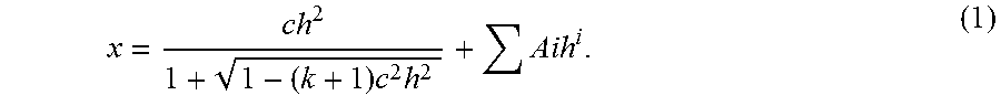
XML
uspto.report is an independent third-party trademark research tool that is not affiliated, endorsed, or sponsored by the United States Patent and Trademark Office (USPTO) or any other governmental organization. The information provided by uspto.report is based on publicly available data at the time of writing and is intended for informational purposes only.
While we strive to provide accurate and up-to-date information, we do not guarantee the accuracy, completeness, reliability, or suitability of the information displayed on this site. The use of this site is at your own risk. Any reliance you place on such information is therefore strictly at your own risk.
All official trademark data, including owner information, should be verified by visiting the official USPTO website at www.uspto.gov. This site is not intended to replace professional legal advice and should not be used as a substitute for consulting with a legal professional who is knowledgeable about trademark law.