Intraocular shunt placement
Horvath , et al. March 9, 2
U.S. patent number 10,940,040 [Application Number 15/882,984] was granted by the patent office on 2021-03-09 for intraocular shunt placement. This patent grant is currently assigned to AQUESYS, INC.. The grantee listed for this patent is AqueSys, Inc.. Invention is credited to Christopher Horvath, Laszlo O. Romoda.


View All Diagrams
| United States Patent | 10,940,040 |
| Horvath , et al. | March 9, 2021 |
Intraocular shunt placement
Abstract
Methods are provided for using an intraocular shunt deployment device to deploy an intraocular shunt from the device and into an eye.
| Inventors: | Horvath; Christopher (Mission Viejo, CA), Romoda; Laszlo O. (San Clemente, CA) | ||||||||||
|---|---|---|---|---|---|---|---|---|---|---|---|
| Applicant: |
|
||||||||||
| Assignee: | AQUESYS, INC. (Aliso Viejo,
CA) |
||||||||||
| Family ID: | 1000005408080 | ||||||||||
| Appl. No.: | 15/882,984 | ||||||||||
| Filed: | January 29, 2018 |
Prior Publication Data
| Document Identifier | Publication Date | |
|---|---|---|
| US 20180147089 A1 | May 31, 2018 | |
Related U.S. Patent Documents
| Application Number | Filing Date | Patent Number | Issue Date | ||
|---|---|---|---|---|---|
| 14843887 | Sep 2, 2015 | 9877866 | |||
| 14191340 | Nov 24, 2015 | 9192516 | |||
| 12946653 | Mar 4, 2014 | 8663303 | |||
| Current U.S. Class: | 1/1 |
| Current CPC Class: | A61F 9/00781 (20130101) |
| Current International Class: | A61F 2/958 (20130101); A61F 9/007 (20060101) |
References Cited [Referenced By]
U.S. Patent Documents
| 3654932 | April 1972 | Newkirk |
| 3788327 | January 1974 | Donowitz et al. |
| 3960150 | June 1976 | Hussain et al. |
| 4090530 | May 1978 | Lange |
| 4402308 | September 1983 | Scott |
| 4562463 | December 1985 | Lipton |
| 4583117 | April 1986 | Lipton et al. |
| 4613329 | September 1986 | Bodicky |
| 4700692 | October 1987 | Baumgartner |
| 4722724 | February 1988 | Schocket |
| 4730613 | March 1988 | Gordy |
| 4744362 | May 1988 | Grundler |
| 4750901 | June 1988 | Molteno |
| 4787885 | November 1988 | Binder |
| 4804382 | February 1989 | Turina et al. |
| 4820626 | April 1989 | Williams et al. |
| 4826478 | May 1989 | Schocket |
| 4836201 | June 1989 | Patton et al. |
| 4848340 | July 1989 | Bille et al. |
| 4863457 | September 1989 | Lee |
| 4902292 | February 1990 | Joseph |
| 4908024 | March 1990 | Py |
| 4911161 | March 1990 | Schechter |
| 4915684 | April 1990 | MacKeen et al. |
| 4934363 | June 1990 | Smith et al. |
| 4936825 | June 1990 | Ungerleider |
| 4946436 | August 1990 | Smith |
| 4968296 | November 1990 | Ritch et al. |
| 4978352 | December 1990 | Fedorov et al. |
| 5041081 | August 1991 | Odrich |
| 5057098 | October 1991 | Zelman |
| 5071408 | December 1991 | Ahmed |
| 5092837 | March 1992 | Ritch et al. |
| 5098426 | March 1992 | Sklar et al. |
| 5098443 | March 1992 | Parel et al. |
| 5162641 | November 1992 | Fountain |
| 5167645 | December 1992 | Castillo |
| 5178604 | January 1993 | Baerveldt et al. |
| 5180362 | January 1993 | Worst |
| 5201750 | April 1993 | Hocherl et al. |
| 5207660 | May 1993 | Lincoff |
| 5273530 | December 1993 | Del Cerro |
| 5275622 | January 1994 | Lazarus |
| 5290295 | March 1994 | Querals et al. |
| 5300020 | April 1994 | L'Esperance, Jr. |
| 5333619 | August 1994 | Burgio |
| 5338291 | August 1994 | Speckman et al. |
| 5342370 | August 1994 | Simon et al. |
| 5351678 | October 1994 | Clayton |
| 5360339 | November 1994 | Rosenberg |
| 5368015 | November 1994 | Wilk |
| 5370607 | December 1994 | Memmen |
| 5399951 | March 1995 | Lavallee et al. |
| 5410638 | April 1995 | Colgate et al. |
| 5443505 | August 1995 | Wong et al. |
| 5476445 | December 1995 | Baerveldt et al. |
| 5516522 | May 1996 | Peyman et al. |
| 5520631 | May 1996 | Nordquist et al. |
| 5558629 | September 1996 | Baerveldt et al. |
| 5558630 | September 1996 | Fisher |
| 5601094 | February 1997 | Reiss |
| 5656026 | August 1997 | Joseph |
| 5665093 | September 1997 | Atkins et al. |
| 5665114 | September 1997 | Weadock et al. |
| 5670161 | September 1997 | Healy et al. |
| 5688562 | November 1997 | Hsiung |
| 5695474 | December 1997 | Daugherty |
| 5704907 | January 1998 | Nordquist et al. |
| 5707376 | January 1998 | Kavteladze et al. |
| 5722948 | March 1998 | Gross |
| 5763491 | June 1998 | Brandt et al. |
| 5868697 | February 1999 | Richter et al. |
| 5908449 | June 1999 | Bruchman et al. |
| 5932299 | August 1999 | Katoot |
| 5938583 | August 1999 | Grimm |
| 5964747 | October 1999 | Eaton et al. |
| 6007511 | December 1999 | Prywes |
| 6007578 | December 1999 | Schachar |
| 6050970 | April 2000 | Baerveldt |
| 6086543 | July 2000 | Anderson et al. |
| 6102045 | August 2000 | Nordquist et al. |
| 6146366 | November 2000 | Schachar |
| 6159218 | December 2000 | Aramant et al. |
| 6165210 | December 2000 | Lau et al. |
| 6203513 | March 2001 | Yaron et al. |
| 6228023 | May 2001 | Zaslavsky et al. |
| 6228873 | May 2001 | Brandt et al. |
| 6231546 | May 2001 | Milo |
| 6261256 | July 2001 | Ahmed |
| 6264665 | July 2001 | Yu et al. |
| 6280468 | August 2001 | Schachar |
| 6413540 | July 2002 | Yaacobi |
| 6450937 | September 2002 | Mercereau et al. |
| 6471666 | October 2002 | Odrich |
| 6483930 | November 2002 | Musgrave et al. |
| 6514238 | February 2003 | Hughes |
| 6524275 | February 2003 | Lynch et al. |
| 6533768 | March 2003 | Hill |
| 6544249 | April 2003 | Yu et al. |
| 6558342 | May 2003 | Yaron et al. |
| 6595945 | July 2003 | Brown |
| 6638239 | October 2003 | Bergheim et al. |
| 6699210 | March 2004 | Williams et al. |
| 6726664 | April 2004 | Yaron et al. |
| D490152 | May 2004 | Myall et al. |
| 6736791 | May 2004 | Tu et al. |
| 6752753 | June 2004 | Hoskins et al. |
| 6881198 | April 2005 | Brown |
| 6936053 | August 2005 | Weiss |
| 6939298 | September 2005 | Brown et al. |
| 7008396 | March 2006 | Straub |
| 7037335 | May 2006 | Freeman et al. |
| 7041077 | May 2006 | Shields |
| 7094225 | August 2006 | Tu et al. |
| 7118547 | October 2006 | Dahan |
| 7135009 | November 2006 | Tu et al. |
| 7163543 | January 2007 | Smedley et al. |
| 7186232 | March 2007 | Smedley et al. |
| 7207980 | April 2007 | Christian et al. |
| 7291125 | November 2007 | Coroneo |
| 7331984 | February 2008 | Tu et al. |
| 7431709 | October 2008 | Pinchuk et al. |
| 7431710 | October 2008 | Tu et al. |
| 7458953 | December 2008 | Peyman |
| 7488303 | February 2009 | Haffner et al. |
| 7594899 | September 2009 | Pinchuk et al. |
| 7625384 | December 2009 | Eriksson et al. |
| 7658729 | February 2010 | Hull |
| 7708711 | May 2010 | Tu et al. |
| 7722549 | May 2010 | Nakao |
| 7837644 | November 2010 | Pinchuk et al. |
| 7867186 | January 2011 | Haffner et al. |
| 7892282 | February 2011 | Shepherd |
| 8109896 | February 2012 | Nissan et al. |
| 8267882 | September 2012 | Euteneuer et al. |
| 8277437 | October 2012 | Saal et al. |
| 8308701 | November 2012 | Horvath et al. |
| 8313454 | November 2012 | Yaron et al. |
| 8337393 | December 2012 | Silverstrini et al. |
| 8337509 | December 2012 | Schieber et al. |
| 8377122 | February 2013 | Silvestrini et al. |
| 8425449 | April 2013 | Wardle et al. |
| 8444589 | May 2013 | Silvestrini |
| 8486000 | July 2013 | Coroneo |
| 8506515 | August 2013 | Burns et al. |
| 8512404 | August 2013 | Frion et al. |
| 8529492 | September 2013 | Clauson et al. |
| 8535333 | September 2013 | de Juan, Jr. et al. |
| 8545430 | October 2013 | Silvestrini |
| 8585629 | November 2013 | Grabner et al. |
| 8597301 | December 2013 | Mitchell |
| 8608632 | December 2013 | Brigatti et al. |
| 8663303 | March 2014 | Horvath et al. |
| 8721702 | May 2014 | Romoda et al. |
| 8758290 | June 2014 | Horvath et al. |
| 8765210 | July 2014 | Romoda et al. |
| 8801766 | August 2014 | Reitsamer et al. |
| 8828070 | September 2014 | Romoda et al. |
| 8852136 | October 2014 | Horvath et al. |
| 8852137 | October 2014 | Horvath et al. |
| 8852256 | October 2014 | Horvath et al. |
| 8974511 | March 2015 | Horvath et al. |
| 9017276 | April 2015 | Horvath et al. |
| 9044301 | June 2015 | Pinchuk et al. |
| 9095411 | August 2015 | Horvath et al. |
| 9095413 | August 2015 | Romoda et al. |
| 9192516 | November 2015 | Horvath et al. |
| 9271869 | March 2016 | Horvath et al. |
| 9283116 | March 2016 | Romoda et al. |
| 9326891 | May 2016 | Horvath et al. |
| 9393153 | July 2016 | Horvath et al. |
| 2001/0025150 | September 2001 | de Juan et al. |
| 2001/0056254 | December 2001 | Cragg et al. |
| 2002/0087149 | July 2002 | McCary |
| 2002/0099434 | July 2002 | Buscemi et al. |
| 2002/0133168 | September 2002 | Smedley et al. |
| 2003/0015203 | January 2003 | Makower et al. |
| 2003/0050574 | March 2003 | Krueger |
| 2003/0060752 | March 2003 | Bergheim et al. |
| 2003/0093084 | May 2003 | Nissan et al. |
| 2003/0097053 | May 2003 | Itoh |
| 2003/0187383 | October 2003 | Weber et al. |
| 2003/0236483 | December 2003 | Ren |
| 2003/0236484 | December 2003 | Lynch et al. |
| 2004/0077987 | April 2004 | Rapacki et al. |
| 2004/0147870 | July 2004 | Burns et al. |
| 2004/0199130 | October 2004 | Chornenky et al. |
| 2004/0210209 | October 2004 | Yeung et al. |
| 2004/0215133 | October 2004 | Weber et al. |
| 2004/0216749 | November 2004 | Tu |
| 2004/0236343 | November 2004 | Taylor et al. |
| 2004/0254521 | December 2004 | Simon |
| 2004/0260227 | December 2004 | Lisk et al. |
| 2005/0049578 | March 2005 | Tu et al. |
| 2005/0101967 | May 2005 | Weber et al. |
| 2005/0143363 | June 2005 | De Juan et al. |
| 2005/0246023 | November 2005 | Yeung |
| 2005/0267398 | December 2005 | Protopsaltis et al. |
| 2005/0271704 | December 2005 | Tu et al. |
| 2005/0277864 | December 2005 | Haffner et al. |
| 2006/0052721 | March 2006 | Dunker et al. |
| 2006/0064112 | March 2006 | Perez |
| 2006/0106370 | May 2006 | Baerveldt et al. |
| 2006/0116625 | June 2006 | Renati et al. |
| 2006/0149194 | July 2006 | Conston et al. |
| 2006/0155238 | July 2006 | Shields |
| 2006/0173397 | August 2006 | Tu et al. |
| 2006/0173446 | August 2006 | Dacquay et al. |
| 2006/0200113 | September 2006 | Haffner et al. |
| 2006/0241411 | October 2006 | Field et al. |
| 2007/0093783 | April 2007 | Kugler et al. |
| 2007/0118065 | May 2007 | Pinchuk et al. |
| 2007/0141116 | June 2007 | Pinchuk et al. |
| 2007/0172903 | July 2007 | Toner et al. |
| 2007/0191863 | August 2007 | De Juan et al. |
| 2007/0263172 | November 2007 | Mura |
| 2007/0293872 | December 2007 | Peyman |
| 2008/0015633 | January 2008 | Abbott et al. |
| 2008/0027304 | January 2008 | Pardo et al. |
| 2008/0057106 | March 2008 | Erickson et al. |
| 2008/0108933 | May 2008 | Yu |
| 2008/0147001 | June 2008 | Al-Marashi et al. |
| 2008/0181929 | July 2008 | Robinson et al. |
| 2008/0249467 | October 2008 | Burnett et al. |
| 2008/0281277 | November 2008 | Thyzel |
| 2008/0312661 | December 2008 | Downer et al. |
| 2009/0036818 | February 2009 | Grahn et al. |
| 2009/0043321 | February 2009 | Conston et al. |
| 2009/0124973 | May 2009 | D'Agostino et al. |
| 2009/0182421 | July 2009 | Silvestrini et al. |
| 2009/0209910 | August 2009 | Kugler et al. |
| 2009/0216106 | August 2009 | Takii |
| 2009/0264813 | October 2009 | Chang |
| 2009/0270890 | October 2009 | Robinson et al. |
| 2009/0281520 | November 2009 | Highley et al. |
| 2009/0287136 | November 2009 | Castillejos |
| 2010/0004581 | January 2010 | Brigatti et al. |
| 2010/0063478 | March 2010 | Selkee |
| 2010/0063512 | March 2010 | Braga |
| 2010/0098772 | April 2010 | Robinson et al. |
| 2010/0100104 | April 2010 | Yu et al. |
| 2010/0119696 | May 2010 | Yu et al. |
| 2010/0121248 | May 2010 | Yu et al. |
| 2010/0121249 | May 2010 | Yu et al. |
| 2010/0134759 | June 2010 | Silvestrini et al. |
| 2010/0137981 | June 2010 | Silvestrini et al. |
| 2010/0173866 | July 2010 | Hee et al. |
| 2010/0191103 | July 2010 | Stamper et al. |
| 2010/0249691 | September 2010 | Van Der Mooren et al. |
| 2010/0328606 | December 2010 | Peyman |
| 2011/0009874 | January 2011 | Wardle et al. |
| 2011/0046536 | February 2011 | Stegmann et al. |
| 2011/0098627 | April 2011 | Wilcox |
| 2011/0105990 | May 2011 | Silvestrini |
| 2011/0118745 | May 2011 | Yu et al. |
| 2011/0118835 | May 2011 | Silvestrini et al. |
| 2011/0230890 | September 2011 | Thyzel |
| 2011/0234976 | September 2011 | Kocaoglu et al. |
| 2012/0123315 | May 2012 | Horvath et al. |
| 2012/0123316 | May 2012 | Horvath et al. |
| 2012/0123317 | May 2012 | Horvath et al. |
| 2012/0123434 | May 2012 | Grabner et al. |
| 2012/0165720 | June 2012 | Horvath et al. |
| 2012/0165933 | June 2012 | Haffner et al. |
| 2012/0197175 | August 2012 | Horvath et al. |
| 2012/0226150 | September 2012 | Balicki et al. |
| 2012/0310137 | December 2012 | Silvestrini |
| 2013/0158462 | June 2013 | Wardle et al. |
| 2013/0184631 | July 2013 | Pinchuk |
| 2013/0211314 | August 2013 | Boey et al. |
| 2013/0237958 | September 2013 | Arrigo |
| 2013/0245573 | September 2013 | de Juan, Jr. et al. |
| 2013/0253528 | September 2013 | Haffner et al. |
| 2013/0281817 | October 2013 | Schaller et al. |
| 2013/0281908 | October 2013 | Schaller et al. |
| 2013/0345515 | December 2013 | Fitzmaaurice |
| 2014/0066833 | March 2014 | Yaron et al. |
| 2014/0081195 | March 2014 | Clauson et al. |
| 2014/0135916 | May 2014 | Clauson et al. |
| 2014/0213958 | July 2014 | Clauson et al. |
| 2014/0236066 | August 2014 | Horvath et al. |
| 2014/0243730 | August 2014 | Horvath |
| 2014/0275923 | September 2014 | Haffner et al. |
| 2014/0276332 | September 2014 | Grimaldi et al. |
| 2014/0277349 | September 2014 | Vad |
| 2014/0303544 | October 2014 | Haffner et al. |
| 2014/0323995 | October 2014 | Clauson et al. |
| 2014/0371651 | December 2014 | Pinchuk |
| 2015/0005689 | January 2015 | Horvath et al. |
| 2015/0011926 | January 2015 | Reitsamer et al. |
| 2015/0038893 | February 2015 | Haffner et al. |
| 2015/0133946 | May 2015 | Horvath et al. |
| 2015/0265469 | September 2015 | Bhandari et al. |
| 2015/0290035 | October 2015 | Horvath et al. |
| 2015/0374545 | December 2015 | Horvath et al. |
| 2016/0135993 | May 2016 | Horvath et al. |
| 2016/0135994 | May 2016 | Romoda et al. |
| 2016/0158063 | June 2016 | Romoda et al. |
| 2018/0199797 | July 2018 | London |
| 2019/0030285 | January 2019 | Prabhu |
| 2019/0054272 | February 2019 | Tal |
| 2019/0069770 | March 2019 | Bourget |
| 2019/0290314 | September 2019 | Gemer |
| 2020/0046213 | February 2020 | Bendory |
| 2020/0054353 | February 2020 | Yun |
| 1402625 | Mar 2003 | CN | |||
| 1909859 | Feb 2007 | CN | |||
| 101677823 | Mar 2010 | CN | |||
| 102170840 | Aug 2011 | CN | |||
| 102481171 | May 2012 | CN | |||
| 102510746 | Jun 2012 | CN | |||
| 2 296 663 | Jul 1996 | GB | |||
| 2009-523540 | Jun 2009 | JP | |||
| 2012-527318 | Nov 2012 | JP | |||
| 2014-500758 | Jan 2014 | JP | |||
| 2313315 | Dec 2007 | RU | |||
| 2482822 | May 2013 | RU | |||
| WO-98/23237 | Jun 1998 | WO | |||
| WO-00/056255 | Sep 2000 | WO | |||
| WO-2002/74052 | Sep 2002 | WO | |||
| WO-2007/087061 | Aug 2007 | WO | |||
| WO-2008/005873 | Jan 2008 | WO | |||
| WO 2010/003011 | Jan 2010 | WO | |||
| WO 2014/150292 | Sep 2014 | WO | |||
| WO 2016/023942 | Feb 2016 | WO | |||
| WO 2017/184881 | Oct 2017 | WO | |||
Other References
|
Pediatric Surgery, vol. e, 7th edition, published on Feb. 14, 2012 to Coran et al., pp. 1673-1697. cited by applicant . Quere, "Fluid Coating on a Fiber," Annu. Rev. Fluid Mech. 1999, 31:347-84. cited by applicant. |
Primary Examiner: Nguyen; Vi X
Attorney, Agent or Firm: Smith; Nathan S. Das; Sujohn Morgan, Lewis & Bockius LLP
Parent Case Text
CROSS-REFERENCE TO RELATED APPLICATIONS
This application is a divisional of U.S. patent application Ser. No. 14/843,887, filed on Sep. 2, 2015, which is a continuation of U.S. patent application Ser. No. 14/191,340, filed on Feb. 26, 2014, now U.S. Pat. No. 9,192,516, which is a continuation of U.S. patent application Ser. No. 12/946,653, filed on Nov. 15, 2010, now U.S. Pat. No. 8,663,303, the entireties of each of which is incorporated herein by reference.
Claims
What is claimed is:
1. A method for deploying an intraocular shunt within an eye, the method comprising: providing a device comprising a hollow shaft configured to hold an intraocular shunt and a sleeve providing a visual preview component disposed along the shaft; inserting the device into a cornea of the eye; advancing the shaft into an anterior chamber angle of the eye; and while maintaining the visual preview component at a substantially fixed position within the anterior chamber, advancing the shunt from the device for assuring optimal longitudinal placement within the eye.
2. The method of claim 1, wherein the advancing the device comprises advancing the shaft into the anterior chamber angle until the visual preview component is positioned at the substantially fixed position, spaced apart from the anterior chamber angle for releasing a proximal end of the shunt at the substantially fixed position after the shunt is advanced from the device.
3. The method of claim 1, wherein in the substantially fixed position, the visual preview component is spaced apart from anterior chamber angle tissue.
4. The method of claim 1, wherein the advancing the device comprises advancing the device until the visual preview component contacts the anterior chamber angle to provide resistance against further advancement of the device.
5. The method of claim 4, wherein the visual preview component comprises a sleeve, the shaft being disposed within the sleeve, and wherein the advancing comprises advancing the device until a distal edge of the sleeve contacts the anterior chamber angle.
6. The method of claim 1, wherein the advancing the shunt is performed while the visual preview component is spaced apart from the anterior chamber angle at the fixed position.
7. The method of claim 1, wherein the device comprises a deployment mechanism at least partially disposed within a housing thereof, and wherein rotation of the deployment mechanism results in axial movement of the shaft relative to the shunt to advance the shunt relative to the shaft, the method further comprising rotating the deployment mechanism to advance the shunt from the device and into the eye.
8. The method of claim 7, wherein the device comprises a sleeve, the shaft disposed within the sleeve, and wherein the rotating causes proximal axial movement of a distal end of the shaft into the sleeve.
9. The method of claim 1, wherein the advancing comprises forming a flow path from an anterior chamber of the eye to an area of lower pressure.
10. The method of claim 9, wherein the area of lower pressure is superficial to an inner surface of sclera.
11. The method of claim 9, wherein the area of lower pressure is selected from the group consisting of: intra-Tenon's space, a subconjunctival space, an episcleral vein, a suprachoroidal space, and Schlemm's canal.
12. A method for deploying an intraocular shunt within an eye, the method comprising: inserting a hollow shaft of a device through a cornea into an anterior chamber angle of the eye; positioning a sleeve providing a visual preview component of the device within the eye at a position spaced apart from the anterior chamber angle; and while maintaining the position of the visual preview component, advancing the shunt from the device for assuring optimal longitudinal placement within the eye.
13. The method of claim 12, further comprising releasing a proximal end of the shunt at the desired location after the shunt is advanced from the device.
14. The method of claim 12, wherein the advancing the device comprises advancing the device until the visual preview component contacts the anterior chamber angle to provide resistance against further advancement of the device.
15. The method of claim 14, wherein the visual preview component comprises a sleeve, the shaft being disposed within the sleeve, and wherein the advancing comprises advancing the device until a distal edge of the sleeve contacts the anterior chamber angle.
16. The method of claim 12, wherein the advancing the device comprises forming a flow path from an anterior chamber of the eye to an area of lower pressure selected from the group consisting of: intra-Tenon's space, a subconjunctival space, an episcleral vein, a suprachoroidal space, and Schlemm's canal.
17. The method of claim 12, wherein the advancing the shunt is performed while the visual preview component is spaced apart from the anterior chamber angle at the fixed position.
18. The method of claim 12, wherein the device comprises a deployment mechanism at least partially disposed within a housing thereof, and wherein rotation of the deployment mechanism results in axial movement of the shaft relative to the shunt to advance the shunt relative to the shaft, the method further comprising rotating the deployment mechanism to advance the shunt from the device and into the eye.
19. The method of claim 18, wherein the device comprises a sleeve, the shaft disposed within the sleeve, and wherein the rotating causes proximal axial movement of a distal end of the shaft into the sleeve.
Description
BACKGROUND
Field of the Invention
The invention generally relates to methods for using an intraocular shunt deployment device to deploy an intraocular shunt from the device and into an eye.
Description of the Related Art
Glaucoma is a disease of the eye that affects millions of people. Glaucoma is associated with an increase in intraocular pressure resulting either from a failure of a drainage system of an eye to adequately remove aqueous humor from an anterior chamber of the eye or overproduction of aqueous humor by a ciliary body in the eye. Build-up of aqueous humor and resulting intraocular pressure may result in irreversible damage to the optic nerve and the retina, which may lead to irreversible retinal damage and blindness.
Glaucoma may be treated by surgical intervention that involves placing a shunt in the eye to result in production of fluid flow pathways between the anterior chamber and various structures of the eye involved in aqueous humor drainage (e.g., Schlemm's canal, the sclera, or the subconjunctival space). Such fluid flow pathways allow for aqueous humor to exit the anterior chamber. Generally, the surgical intervention to implant the shunt involves inserting into the eye a deployment device that holds an intraocular shunt, and deploying the shunt within the eye. A deployment device holding the shunt enters the eye through a cornea (ab interno approach), and is advanced across the anterior chamber. The deployment device is advanced through the sclera until a distal portion of the device is in proximity to a drainage structure of the eye. The shunt is then deployed from the deployment device, producing a conduit between the anterior chamber and various structures of the eye involved in aqueous humor drainage (e.g., Schlemm's canal, the sclera, or the subconjunctival space). See for example, Prywes (U.S. Pat. No. 6,007,511).
A problem associated with such surgical interventions is ensuring that placement of the shunt does not change during deployment of the shunt from the deployment device. Deployment devices that are used to place the shunt in the eye generally rely on multiple moving components in order to deploy the shunt. Movement of the components of the deployment device shifts the position of the deployment device within the eye during the deployment process, and thus shifts the position of the shunt as it is being deployed. Such movement leads to improper placement of the shunt within the eye.
SUMMARY
The invention generally relates to deployment devices that are designed to minimize movement of the device during deployment of an intraocular shunt from the device, thereby ensuring proper placement of the shunt within the eye.
In certain aspects, deployment devices of the invention include a housing, a deployment mechanism at least partially disposed within the housing, and a hollow shaft coupled to the deployment mechanism, in which the shaft is configured to hold an intraocular shunt. With such devices, rotation of the deployment mechanism results in deployment of the shunt. Such rotational movement is translated into axial movement for deploying the shunt from the device. By utilizing rotational movement for the deployment mechanism, axial movement of the deployment device is minimized, ensuring proper placement of the shunt within the eye.
Other aspects of the invention provide devices for deploying an intraocular shunt including a housing, a deployment mechanism at least partially disposed within the housing, in which the deployment mechanism includes a two stage system, and a hollow shaft coupled to the deployment mechanism, in which the shaft is configured to hold an intraocular shunt.
Another aspect of the invention includes devices for deploying an intraocular shunt including a housing, a deployment mechanism at least partially disposed within the housing, and a hollow shaft coupled inside the housing to the deployment mechanism, wherein the shaft is configured to hold an intraocular shunt, in which the device includes an insertion configuration and a deployment configuration and the deployment configuration includes a proximal portion of the shaft being at least partially retracted to within the housing. In certain embodiments, the insertion configuration includes a distal portion of the shaft being disposed within the housing and a proximal portion of the shaft extending beyond the housing.
In certain embodiments, the shaft is configured to at least partially retract to within the housing. However, it will be appreciated that the shaft may fully retract to within the housing.
In certain embodiments, the device further includes the intraocular shunt. The shunt may be completely disposed within the hollow shaft of the device. Alternatively, the shunt is partially disposed within the hollow shaft of the device.
The deployment mechanism may include a two stage system. In such embodiments, the first stage is a pusher component and the second stage is a retraction component. In this embodiment, rotation of the deployment mechanism sequentially engages the pusher component and then the retraction component. The pusher component pushes the shunt to partially deploy the shunt from within the shaft, and the retraction component retracts the shaft from around the shunt, thereby deploying the shunt. In certain embodiments, the deployment mechanism may additionally include at least one member that limits axial movement of the shaft.
The hollow shaft of the deployment device may include a beveled distal end. An exemplary hollow shaft is a needle. Devices of the invention may be completely automated, partially automated, or completely manual. Devices of the invention may be connected to larger robotic systems or may be used as stand-alone handheld deployment devices. In particular embodiments, the device is a handheld device.
Devices of the invention may include an indicator that provides feedback to an operator as to the state of the deployment mechanism. The indicator may be any type of indicator known in the art, for example a visual indicator, an audio indicator, or a tactile indicator. In certain embodiments, the indicator is a visual indicator.
Aspects of the invention also include methods for deploying an intraocular shunt within an eye. These methods involve using devices described herein to deploy an intraocular shunt from the device within the eye. Generally, deploying the shunt results in a flow path from an anterior chamber of the eye to an area of lower pressure. Exemplary areas of lower pressure include intra-Tenon's space, the subconjunctival space, the episcleral vein, the suprachoroidal space, and Schlemm's canal. In certain embodiments, the area of lower pressure is the subarachnoid space.
Any of a variety of methods known in the art may be used to insert devices of the invention into an eye. In certain embodiments, devices of the invention may be inserted into the eye using an ab externo approach (entering through the conjunctiva) or an ab interno approach (entering through the cornea).
BRIEF DESCRIPTION OF THE DRAWINGS
FIG. 1 is a schematic showing an embodiment of a shunt deployment device according to the invention.
FIG. 2 shows an exploded view of the device shown in FIG. 1.
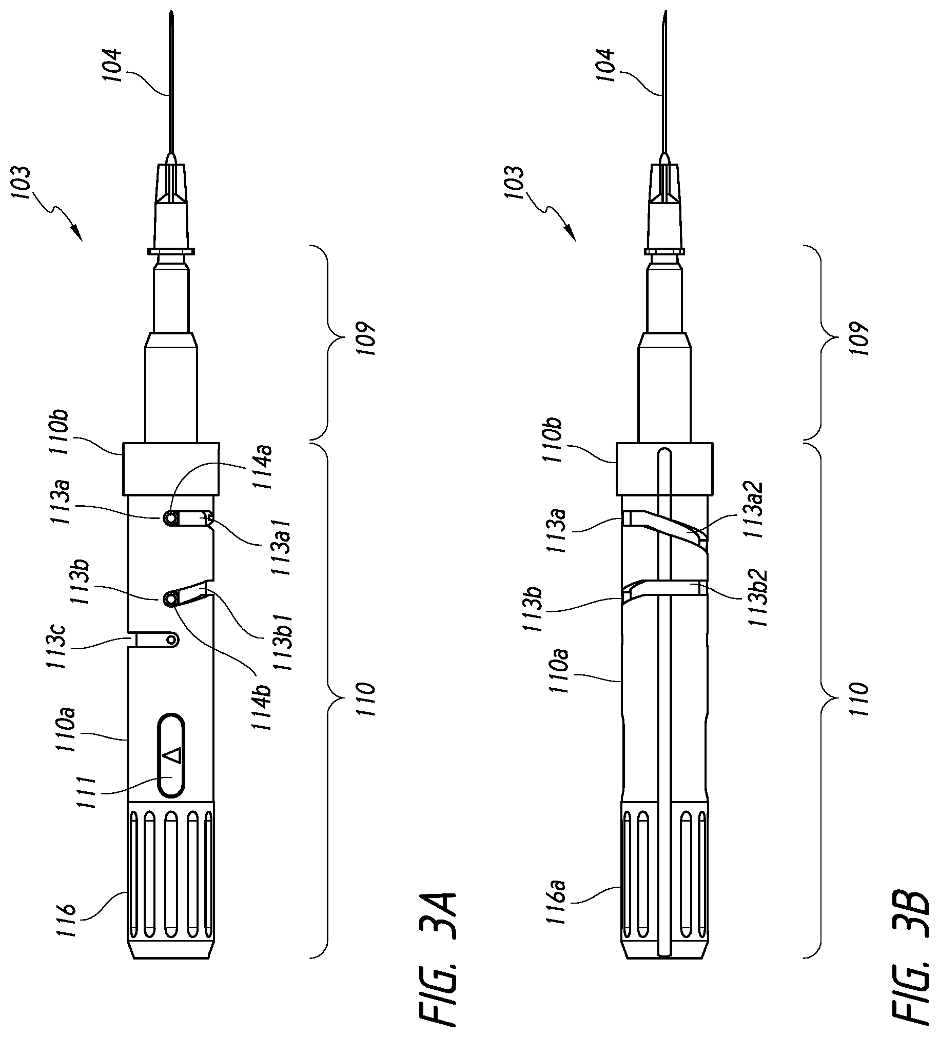
FIGS. 3A-3D are schematics showing different enlarged views of the deployment mechanism of the deployment device.
FIGS. 4A-4C are schematics showing interaction of the deployment mechanism with a portion of the housing of the deployment device.
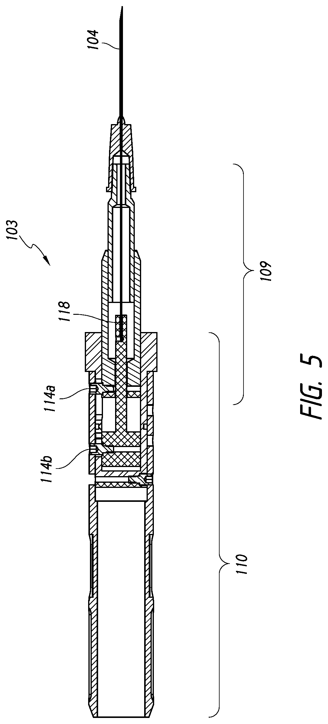
FIG. 5 shows a cross sectional view of the deployment mechanism of the deployment device.
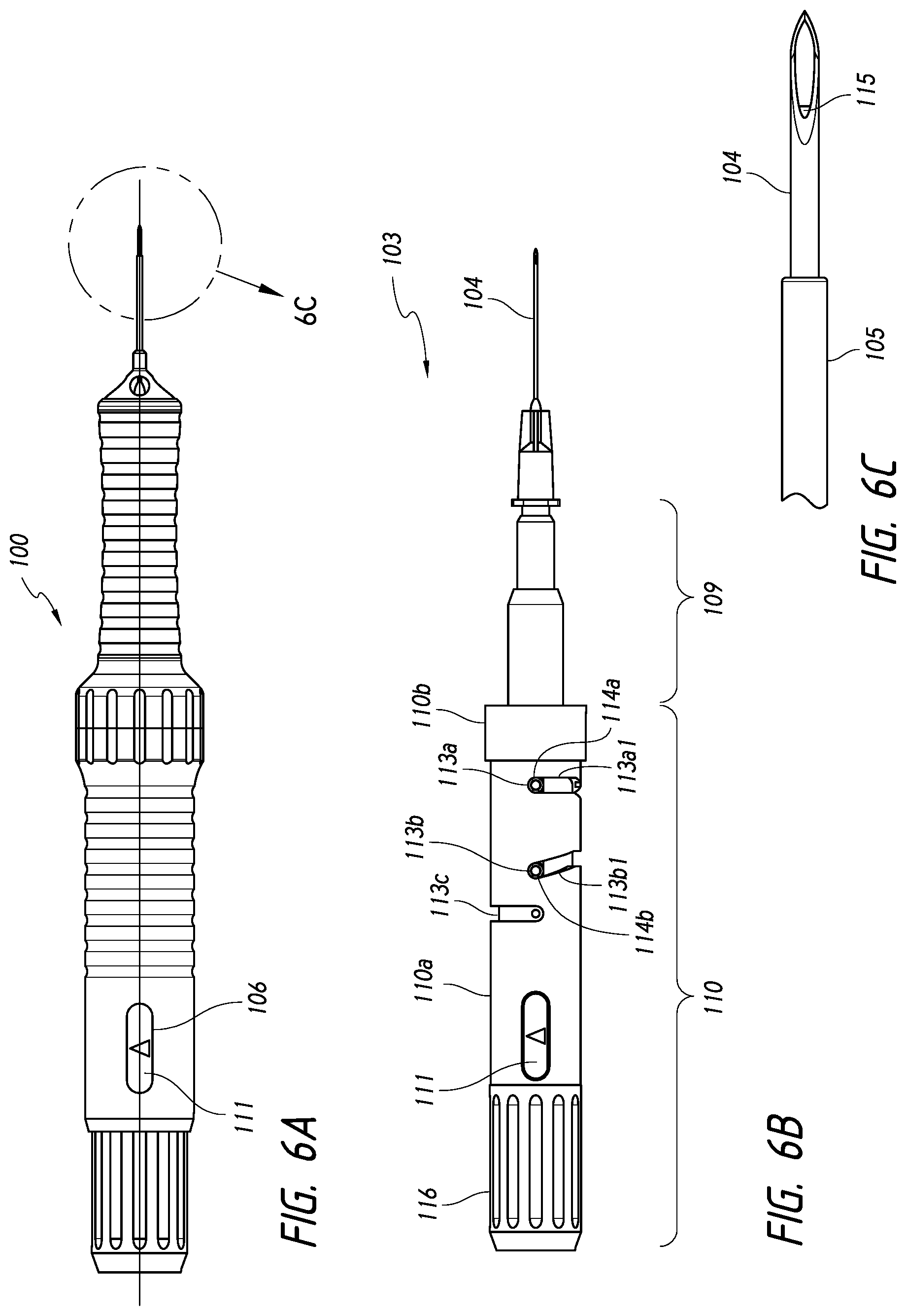
FIGS. 6A and 6B show schematics of the deployment mechanism in a pre-deployment configuration.
FIG. 6C shows an enlarged view of the distal portion of the deployment device of FIG. 6A. This figure shows an intraocular shunt loaded within a hollow shaft of the deployment device.
FIGS. 7A and 7B show schematics of the deployment mechanism at the end of the first stage of deployment of the shunt from the deployment device.
FIG. 7C shows an enlarged view of the distal portion of the deployment device of FIG. 7A. This figure shows an intraocular shunt partially deployed from within a hollow shaft of the deployment device.
FIG. 8A shows a schematic of the deployment device after deployment of the shunt from the device.
FIG. 8B show a schematic of the deployment mechanism at the end of the second stage of deployment of the shunt from the deployment device.
FIG. 8C shows an enlarged view of the distal portion of the deployment device after retraction of the shaft with the pusher abutting the shunt.
FIG. 8D shows an enlarged view of the distal portion of the deployment device after deployment of the shunt.
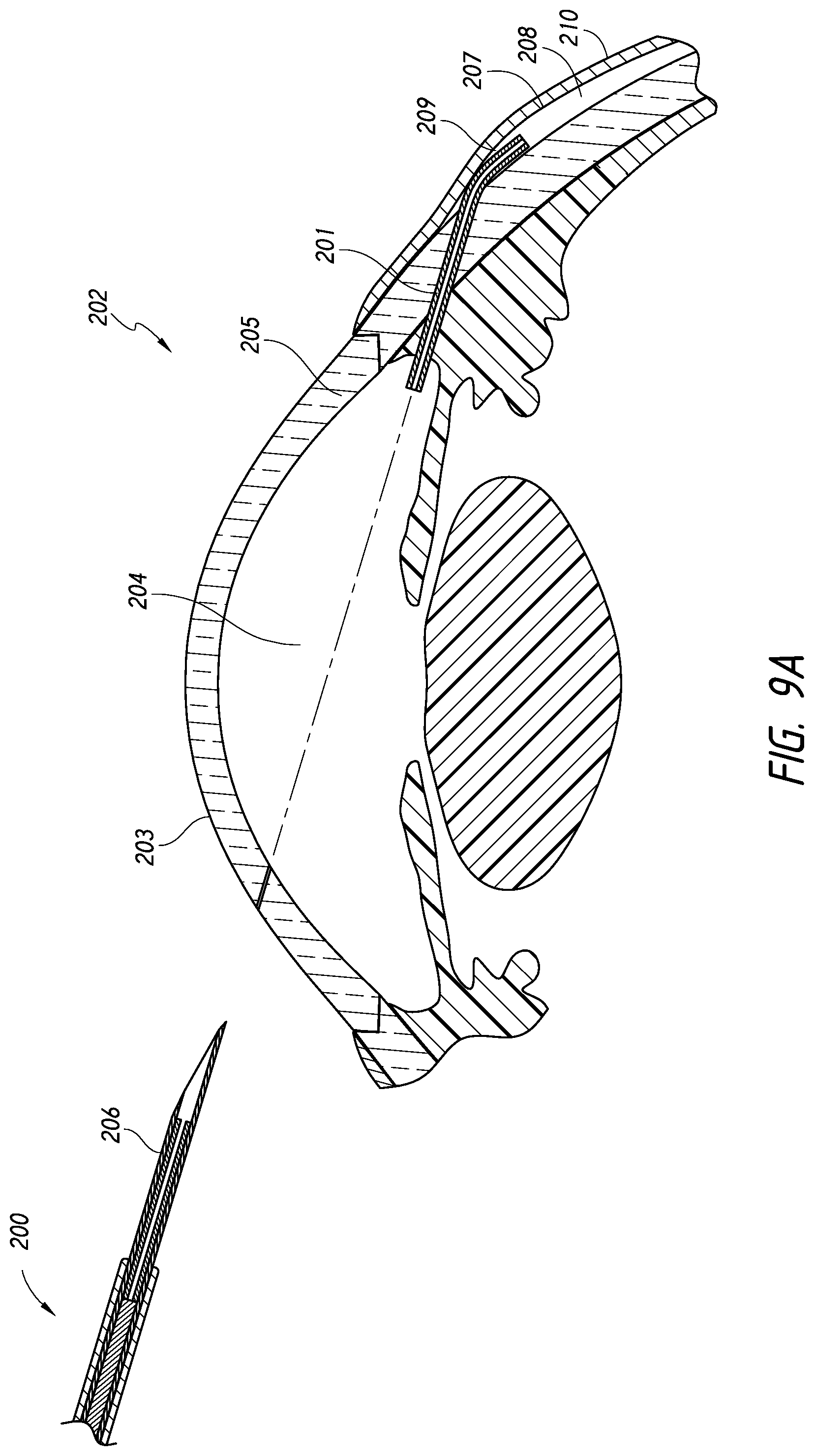
FIGS. 9A and 9B show an intraocular shunt deployed within the eye. A proximal portion of the shunt resides in the anterior chamber and a distal portion of the shunt resides within the intra-Tenon's space. A middle portion of the shunt resides in the sclera.
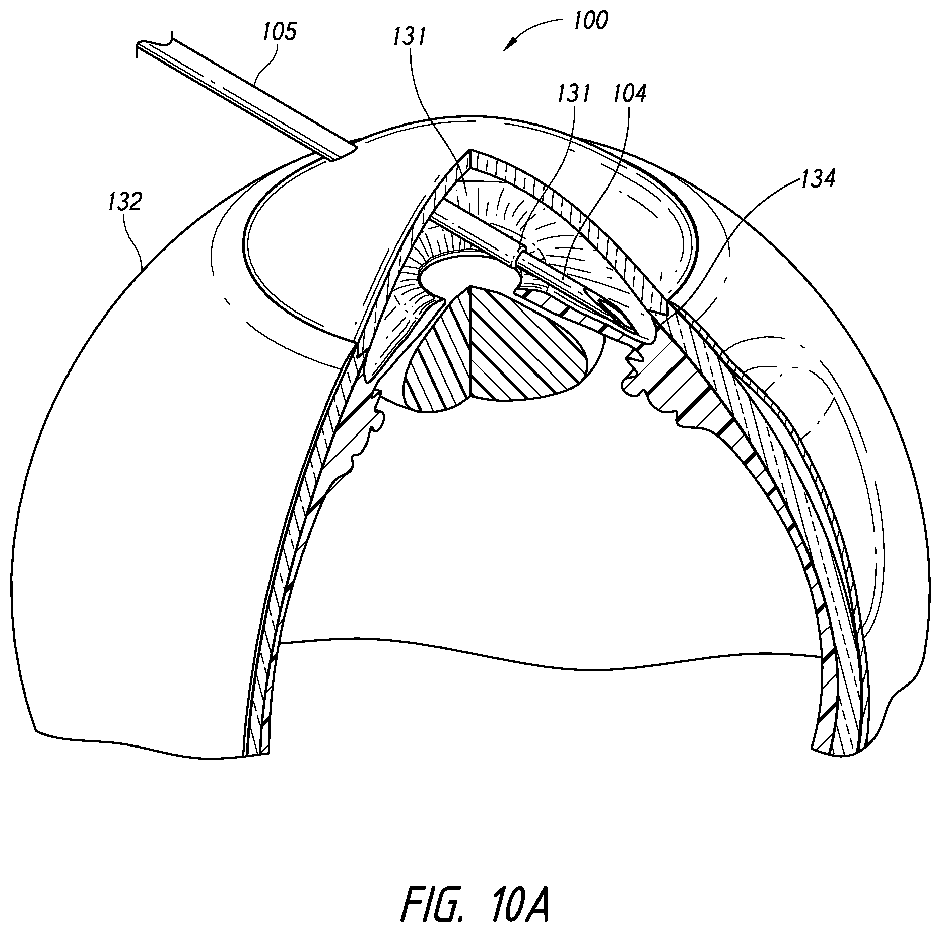
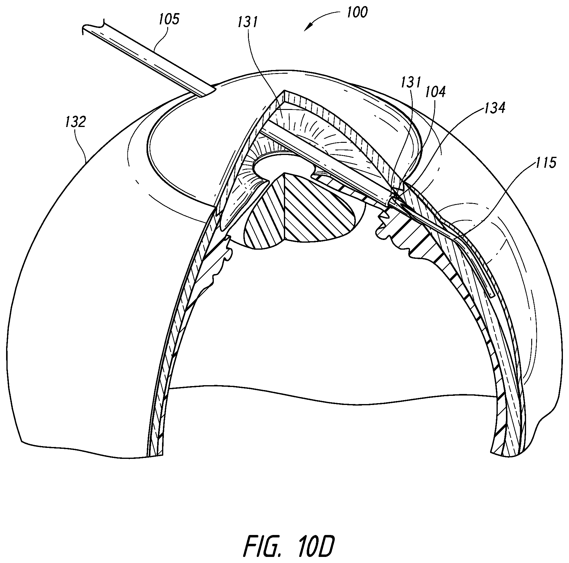
FIGS. 10A-10E show an intraocular shunt being deployed within the eye, according to another embodiment.
FIG. 11 depicts a schematic of an exemplary intraocular shunt.
DETAILED DESCRIPTION
Reference is now made to FIG. 1, which shows an embodiment of a shunt deployment device 100 according to the invention. While FIG. 1 shows a handheld manually operated shunt deployment device, it will be appreciated that devices of the invention may be coupled with robotic systems and may be completely or partially automated. As shown in FIG. 1, deployment device 100 includes a generally cylindrical body or housing 101; however, the body shape of housing 101 could be other than cylindrical. Housing 101 may have an ergonomical shape, allowing for comfortable grasping by an operator. Housing 101 is shown with optional grooves 102 to allow for easier gripping by a surgeon.
Housing 101 is shown having a larger proximal portion that tapers to a distal portion. The distal portion includes a hollow sleeve 105. The hollow sleeve 105 is configured for insertion into an eye and to extend into an anterior chamber of an eye. The hollow sleeve is visible within an anterior chamber of an eye. The sleeve 105 provides a visual preview for an operator as to placement of the proximal portion of the shunt within the anterior chamber of an eye. Additionally, the sleeve 105 provides a visual reference point that may be used by an operator to hold device 100 steady during the shunt deployment process, thereby assuring optimal longitudinal placement of the shunt within the eye.
The sleeve 105 may include an edge 131 at a distal end that provides resistance feedback to an operator upon insertion of the deployment device 100 within an eye 132 of a person during delivery of the shunt 115, as shown in FIGS. 10A-10E. Upon advancement of the device 100 across an anterior chamber 133 of the eye 132, the hollow sleeve 105 will eventually contact the sclera 134, providing resistance feedback to an operator that no further advancement of the device 100 is necessary. The edge 131 of the sleeve 105 prevents the shaft 104 from accidentally being pushed too far through the sclera 134. A temporary guard 108 is configured to fit around sleeve 105 and extend beyond an end of sleeve 105. The guard is used during shipping of the device and protects an operator from a distal end of a hollow shaft 104 that extends beyond the end of the sleeve 105. The guard is removed prior to use of the device.
Housing 101 is open at its proximal end, such that a portion of a deployment mechanism 103 may extend from the proximal end of the housing 101. A distal end of housing 101 is also open such that at least a portion of a hollow shaft 104 may extend through and beyond the distal end of the housing 101. Housing 101 further includes a slot 106 through which an operator, such as a surgeon, using the device 100 may view an indicator 107 on the deployment mechanism 103.
Housing 101 may be made of any material that is suitable for use in medical devices. For example, housing 101 may be made of a lightweight aluminum or a biocompatible plastic material. Examples of such suitable plastic materials include polycarbonate and other polymeric resins such as DELRIN and ULTEM. In certain embodiments, housing 101 is made of a material that may be autoclaved, and thus allow for housing 101 to be re-usable. Alternatively, device 100 may be sold as a one-time-use device, and thus the material of the housing does not need to be a material that is autoclavable.
Housing 101 may be made of multiple components that connect together to form the housing. FIG. 2 shows an exploded view of deployment device 100. In this figure, housing 101, is shown having three components 101a, 101b, and 101c. The components are designed to screw together to form housing 101. FIG. 2 also shows deployment mechanism 103. The housing 101 is designed such that deployment mechanism 103 fits within assembled housing 101. Housing 101 is designed such that components of deployment mechanism 103 are movable within housing 101.
FIGS. 3A-3D show different enlarged views of the deployment mechanism 103. Deployment mechanism 103 may be made of any material that is suitable for use in medical devices. For example, deployment mechanism 103 may be made of a lightweight aluminum or a biocompatible plastic material. Examples of such suitable plastic materials include polycarbonate and other polymeric resins such as DELRIN and ULTEM. In certain embodiments, deployment mechanism 103 is made of a material that may be autoclaved, and thus allow for deployment mechanism 103 to be re-usable. Alternatively, device 100 may be sold as a one-time-use device, and thus the material of the deployment mechanism does not need to be a material that is autoclavable.
Deployment mechanism 103 includes a distal portion 109 and a proximal portion 110. The deployment mechanism 103 is configured such that distal portion 109 is movable within proximal portion 110. More particularly, distal portion 109 is capable of partially retracting to within proximal portion 110.
In this embodiment, the distal portion 109 is shown to taper to a connection with a hollow shaft 104. This embodiment is illustrated such that the connection between the hollow shaft 104 and the distal portion 109 of the deployment mechanism 103 occurs inside the housing 101. In other embodiments, the connection between hollow shaft 104 and the distal portion 109 of the deployment mechanism 103 may occur outside of the housing 101. Hollow shaft 104 may be removable from the distal portion 109 of the deployment mechanism 103. Alternatively, the hollow shaft 104 may be permanently coupled to the distal portion 109 of the deployment mechanism 103.
Generally, hollow shaft 104 is configured to hold an intraocular shunt 115. An exemplary intraocular shunt 115 is shown in FIG. 11. Other exemplary intraocular shunts are shown in Yu et al. (U.S. Patent Application No. 2008/0108933). Generally, in one embodiment, intraocular shunts are of a cylindrical shape and have an outside cylindrical wall and a hollow interior. The shunt may have an inner diameter of approximately 50 .mu.m to approximately 250 .mu.m, an outside diameter of approximately 190 .mu.m to approximately 300 .mu.m, and a length of approximately 0.5 mm to about 20 mm. Thus, hollow shaft 104 is configured to at least hold a shunt of such shape and such dimensions. However, hollow shaft 104 may be configured to hold shunts of different shapes and different dimensions than those described above, and the invention encompasses a shaft 104 that may be configured to hold any shaped or dimensioned intraocular shunt. In particular embodiments, the shaft has an inner diameter of approximately 200 .mu.m to approximately 400 .mu.m.
The shaft 104 may be any length. A usable length of the shaft may be anywhere from about 5 mm to about 40 mm, and is 15 mm in certain embodiments. In certain embodiments, the shaft is straight. In other embodiments, shaft is of a shape other than straight, for example a shaft having a bend along its length or a shaft having an arcuate portion. Exemplary shaped shafts are shown for example in Yu et al. (U.S. Patent Application No. 2008/0108933). In particular embodiments, the shaft includes a bend at a distal portion of the shaft. In other embodiments, a distal end of the shaft is beveled or is sharpened to a point.
The shaft 104 may hold the shunt at least partially within the hollow interior of the shaft 104. In other embodiments, the shunt is held completely within the hollow interior of the shaft 104. Alternatively, the hollow shaft may hold the shunt on an outer surface of the shaft 104. In particular embodiments, the shunt is held within the hollow interior of the shaft 104. In certain embodiments, the hollow shaft is a needle having a hollow interior. Needles that are configured to hold an intraocular shunt are commercially available from Terumo Medical Corp. (Elkington, Md.).
A proximal portion of the deployment mechanism includes optional grooves 116 to allow for easier gripping by an operator for easier rotation of the deployment mechanism, which will be discussed in more detail below. The proximal portion 110 of the deployment mechanism also includes at least one indicator that provides feedback to an operator as to the state of the deployment mechanism. The indicator may be any type of indicator known in the art, for example, a visual indicator, an audio indicator, or a tactile indicator. FIGS. 3A-3D show a deployment mechanism having two indicators, a ready indicator 111 and a deployed indicator 119. Ready indicator 111 provides feedback to an operator that the deployment mechanism is in a configuration for deployment of an intraocular shunt from the deployment device 100. The indicator 111 is shown in this embodiment as a green oval having a triangle within the oval. Deployed indicator 119 provides feedback to the operator that the deployment mechanism has been fully engaged and has deployed the shunt from the deployment device 100. The deployed indicator 119 is shown in this embodiment as a yellow oval having a black square within the oval. The indicators are located on the deployment mechanism such that when assembled, the indicators 111 and 119 may be seen through slot 106 in housing 101.
The proximal portion 110 includes a stationary portion 110b and a rotating portion 110a. The proximal portion 110 includes a channel 112 that runs part of the length of stationary portion 110b and the entire length of rotating portion 110a. The channel 112 is configured to interact with a protrusion 117 on an interior portion of housing component 101a (FIGS. 4A and 4B). During assembly, the protrusion 117 on housing component 101a is aligned with channel 112 on the stationary portion 110b and rotating portion 110a of the deployment mechanism 103. The proximal portion 110 of deployment mechanism 103 is slid within housing component 101a until the protrusion 117 sits within stationary portion 110b (FIG. 4C). Assembled, the protrusion 117 interacts with the stationary portion 110b of the deployment mechanism 103 and prevents rotation of stationary portion 110b. In this configuration, rotating portion 110a is free to rotate within housing component 101a.
Referring back to FIGS. 3A-3D, the rotating portion 110a of proximal portion 110 of deployment mechanism 103 also includes channels 113a, 113b, and 113c. Channel 113a includes a first portion 113a1 that is straight and runs perpendicular to the length of the rotating portion 110a, and a second portion 113a2 that runs diagonally along the length of rotating portion 110a, downwardly toward a proximal end of the deployment mechanism 103. Channel 113b includes a first portion 113b1 that runs diagonally along the length of the rotating portion 110a, downwardly toward a distal end of the deployment mechanism 103, and a second portion that is straight and runs perpendicular to the length of the rotating portion 110a. The point at which first portion 113a1 transitions to second portion 113a2 along channel 113a, is the same as the point at which first portion 113b1 transitions to second portion 113b2 along channel 113b. Channel 113c is straight and runs perpendicular to the length of the rotating portion 110a. Within each of channels 113a, 113b, and 113c, sit members 114a, 114b, and 114c respectively. Members 114a, 114b, and 114c are movable within channels 113a, 113b, and 113c. Members 114a, 114b, and 114c also act as stoppers that limit movement of rotating portion 110a, which thereby limits axial movement of the shaft 104.
FIG. 5 shows a cross-sectional view of deployment mechanism 103. Member 114a is connected to the distal portion 109 of the deployment mechanism 103. Movement of member 114a results in retraction of the distal portion 109 of the deployment mechanism 103 to within the proximal portion 110 of the deployment mechanism 103. Member 114b is connected to a pusher component 118. The pusher component 118 extends through the distal portion 109 of the deployment mechanism 103 and extends into a portion of hollow shaft 104. The pusher component is involved in deployment of a shunt from the hollow shaft 104. An exemplary pusher component is a plunger. Movement of member 114b engages pusher 118 and results in pusher 118 advancing within hollow shaft 104.
Reference is now made to FIGS. 6A-8D, which accompany the following discussion regarding deployment of a shunt 115 from deployment device 100. FIG. 6A shows deployment device 100 in a pre-deployment configuration. In this configuration, shunt 115 is loaded within hollow shaft 104 (FIG. 6C). As shown in FIG. 6C, shunt 115 is only partially within shaft 104, such that a portion of the shunt is exposed. However, the shunt 115 does not extend beyond the end of the shaft 104. In other embodiments, the shunt 115 is completely disposed within hollow shaft 104. The shunt 115 is loaded into hollow shaft 104 such that the shunt abuts pusher component 118 within hollow shaft 104. A distal end of shaft 104 is beveled to assist in piercing tissue of the eye.
Additionally, in the pre-deployment configuration, a portion of the shaft 104 extends beyond the sleeve 105 (FIG. 6C). The deployment mechanism is configured such that member 114a abuts a distal end of the first portion 113a1 of channel 113a, and member 114b abut a proximal end of the first portion 113b1 of channel 113b (FIG. 6B). In this configuration, the ready indicator 111 is visible through slot 106 of the housing 101, providing feedback to an operator that the deployment mechanism is in a configuration for deployment of an intraocular shunt from the deployment device 100 (FIG. 6A). In this configuration, the device 100 is ready for insertion into an eye (insertion configuration or pre-deployment configuration). Methods for inserting and implanting shunts are discussed in further detail below.
Once the device has been inserted into the eye and advanced to a location to where the shunt will be deployed, the shunt 115 may be deployed from the device 100. The deployment mechanism 103 is a two-stage system. The first stage is engagement of the pusher component 118 and the second stage is retraction of the distal portion 109 to within the proximal portion 110 of the deployment mechanism 103. Rotation of the rotating portion 110a of the proximal portion 110 of the deployment mechanism 103 sequentially engages the pusher component and then the retraction component.
In the first stage of shunt deployment, the pusher component is engaged and the pusher partially deploys the shunt from the deployment device. During the first stage, rotating portion 110a of the proximal portion 110 of the deployment mechanism 103 is rotated, resulting in movement of members 114a and 114b along first portions 113a1 and 113b1 in channels 113a and 113b. Since the first portion 113a1 of channel 113a is straight and runs perpendicular to the length of the rotating portion 110a, rotation of rotating portion 110a does not cause axial movement of member 114a. Without axial movement of member 114a, there is no retraction of the distal portion 109 to within the proximal portion 110 of the deployment mechanism 103. Since the first portion 113b1 of channel 113b runs diagonally along the length of the rotating portion 110a, upwardly toward a distal end of the deployment mechanism 103, rotation of rotating portion 110a causes axial movement of member 114b toward a distal end of the device. Axial movement of member 114b toward a distal end of the device results in forward advancement of the pusher component 118 within the hollow shaft 104. Such movement of pusher component 118 results in partially deployment of the shunt 115 from the shaft 104.
FIGS. 7A-7C show schematics of the deployment mechanism at the end of the first stage of deployment of the shunt from the deployment device. As is shown FIG. 7A, members 114a and 114b have finished traversing along first portions 113a1 and 113b1 of channels 113a and 113b. Additionally, pusher component 118 has advanced within hollow shaft 104 (FIG. 7B), and shunt 115 has been partially deployed from the hollow shaft 104 (FIG. 7C). As is shown in these figures, a portion of the shunt 115 extends beyond an end of the shaft 104.
In the second stage of shunt deployment, the retraction component is engaged and the distal portion of the deployment mechanism is retracted to within the proximal portion of the deployment mechanism, thereby completing deployment of the shunt from the deployment device. During the second stage, rotating portion 110a of the proximal portion 110 of the deployment mechanism 103 is further rotated, resulting in movement of members 114a and 114b along second portions 113a2 and 113b2 in channels 113a and 113b. Since the second portion 113b2 of channel 113b is straight and runs perpendicular to the length of the rotating portion 110a, rotation of rotating portion 110a does not cause axial movement of member 114b. Without axial movement of member 114b, there is no further advancement of pusher 118. Since the second portion 113a2 of channel 113a runs diagonally along the length of the rotating portion 110a, downwardly toward a proximal end of the deployment mechanism 103, rotation of rotating portion 110a causes axial movement of member 114a toward a proximal end of the device. Axial movement of member 114a toward a proximal end of the device results in retraction of the distal portion 109 to within the proximal portion 110 of the deployment mechanism 103. Retraction of the distal portion 109, results in retraction of the hollow shaft 104. Since the shunt 115 abuts the pusher component 118, the shunt remains stationary as the hollow shaft 104 retracts from around the shunt 115 (FIG. 8C). The shaft 104 retracts almost completely to within the sleeve 105. During both stages of the deployment process, the sleeve 105 remains stationary and in a fixed position.
FIG. 8A-8D show schematics of the device 100 after deployment of the shunt 115 from the device 100. FIG. 8B shows a schematic of the deployment mechanism at the end of the second stage of deployment of the shunt from the deployment device. As is shown in FIG. 8B, members 114a and 114b have finished traversing along second portions 113a2 and 113b2 of channels 113a and 113b. Additionally, distal portion 109 has retracted to within proximal portion 110, thus resulting in retraction of the hollow shaft 104 to within the sleeve 105. FIG. 8D shows an enlarged view of the proximal portion of the deployment device after deployment of the shunt. This figure shows that the hollow shaft 104 is not fully retracted to within the sleeve 105 of the deployment device 100. However, in certain embodiments, the shaft 104 may completely retract to within the sleeve 105.
Referring to FIG. 8A, in the post-deployment configuration, the deployed indicator 119 is visible through slot 106 of the housing 101, providing feedback to the operator that the deployment mechanism has been fully engaged and that the shunt 115 has been deployed from the deployment device 100.
Any of a variety of methods known in the art may be used to insert devices of the invention into an eye. In certain embodiments, devices of the invention may be inserted into the eye using an ab externo approach (entering through the conjunctiva) or an ab interno approach (entering through the cornea).
In certain embodiments, devices of the invention are inserted into the eye using an ab interno approach. Ab interno approaches for implanting an intraocular shunt are shown for example in Yu et al. (U.S. Pat. No. 6,544,249 and U.S. Patent Application No. 2008/0108933) and Prywes (U.S. Pat. No. 6,007,511), the content of each of which is incorporated by reference herein in its entirety.
Devices of the invention may be inserted into the eye to deploy shunts that create fluid drainage passageways from the anterior chamber of the eye to various drainage structures of the eye. Exemplary drainage structures include Schlemm's canal, the subconjunctival space, the episcleral vein, the suprachoroidal space, or the intra-Tenon's space. In certain embodiments, fluid is drained to the subarachnoid space.
In particular embodiments, devices of the invention are inserted into the eye to deploy shunts that create fluid drainage passageways from the anterior chamber to the intra-Tenon's space. Within an eye, there is a membrane known as the conjunctiva, and the region below the conjunctiva is known as the subconjunctival space. Within the subconjunctival space is a membrane known as Tenon's capsule. Below Tenon's capsule there are Tenon's adhesions that connect the Tenon's capsule to the sclera. The space between Tenon's capsule and the sclera where the Tenon's adhesions connect the Tenon's capsule to the sclera is known as the intra-Tenon's space.
FIGS. 9A and 9B show an intraocular shunt placed into the eye using devices of the invention such that the shunt forms a passage for fluid drainage from the anterior chamber to the intra-Tenon's space. To place the shunt within the eye, a surgical intervention to implant the shunt is performed that involves inserting into the eye 202 a deployment device 200 that holds an intraocular shunt 201, and deploying at least a portion of the shunt 201 within intra-Tenon's space 208, within the subconjunctival space 209 and below the conjunctiva 210. In certain embodiments, a hollow shaft 206 of a deployment device 200 holding the shunt 201 enters the eye 202 through the cornea 203 (ab interno approach). The shaft 206 is advanced across the anterior chamber 204 (as depicted by the broken line) in what is referred to as a transpupil implant insertion. The shaft 206 is advanced through the sclera 205 until a distal portion of the shaft 206 is in proximity to Tenon's capsule 207.
Once a distal portion of the hollow shaft 206 is within the intra-Tenon's space 208, the shunt 201 is then deployed from the shaft 206 of the deployment device 200, producing a conduit between the anterior chamber 204 and the intra-Tenon's space 208 to allow aqueous humor to drain from the anterior chamber 204 (see FIGS. 9A and 9B).
Combinations of Embodiments
As will be appreciated by one skilled in the art, individual features of the invention may be used separately or in any combination. Particularly, it is contemplated that one or more features of the individually described above embodiments may be combined into a single shunt.
Incorporation by Reference
References and citations to other documents, such as patents, patent applications, patent publications, journals, books, papers, web contents, have been made throughout this disclosure. All such documents are hereby incorporated herein by reference in their entirety for all purposes.
EQUIVALENTS
The invention may be embodied in other specific forms without departing from the spirit or essential characteristics thereof. The foregoing embodiments are therefore to be considered in all respects illustrative rather than limiting on the invention described herein.
* * * * *
D00000
D00001
D00002
D00003
D00004
D00005
D00006
D00007
D00008
D00009
D00010
D00011
D00012

D00013
D00014

D00015

D00016
D00017

D00018

XML
uspto.report is an independent third-party trademark research tool that is not affiliated, endorsed, or sponsored by the United States Patent and Trademark Office (USPTO) or any other governmental organization. The information provided by uspto.report is based on publicly available data at the time of writing and is intended for informational purposes only.
While we strive to provide accurate and up-to-date information, we do not guarantee the accuracy, completeness, reliability, or suitability of the information displayed on this site. The use of this site is at your own risk. Any reliance you place on such information is therefore strictly at your own risk.
All official trademark data, including owner information, should be verified by visiting the official USPTO website at www.uspto.gov. This site is not intended to replace professional legal advice and should not be used as a substitute for consulting with a legal professional who is knowledgeable about trademark law.