Wearable electronic device with haptic rotatable input
Pandya , et al. March 2, 2
U.S. patent number 10,936,071 [Application Number 16/377,197] was granted by the patent office on 2021-03-02 for wearable electronic device with haptic rotatable input. This patent grant is currently assigned to Apple Inc.. The grantee listed for this patent is Apple Inc.. Invention is credited to Steven P. Cardinali, Erik G. de Jong, Colin M. Ely, Benjamin G. Jackson, Lei Ma, Sameer Pandya, Steven C. Roach.


View All Diagrams
| United States Patent | 10,936,071 |
| Pandya , et al. | March 2, 2021 |
Wearable electronic device with haptic rotatable input
Abstract
One embodiment described herein takes the form of a watch, comprising: a housing; a crown comprising: a crown body outside the housing; and a shaft extending from the crown body into the housing; and an actuator coupled to the crown and configured to provide haptic output through the crown.
| Inventors: | Pandya; Sameer (Sunnyvale, CA), de Jong; Erik G. (San Francisco, CA), Ely; Colin M. (Sunnyvale, CA), Jackson; Benjamin G. (Belmont, CA), Ma; Lei (San Jose, CA), Roach; Steven C. (San Francisco, CA), Cardinali; Steven P. (Campbell, CA) | ||||||||||
|---|---|---|---|---|---|---|---|---|---|---|---|
| Applicant: |
|
||||||||||
| Assignee: | Apple Inc. (Cupertino,
CA) |
||||||||||
| Family ID: | 1000005394627 | ||||||||||
| Appl. No.: | 16/377,197 | ||||||||||
| Filed: | April 6, 2019 |
Prior Publication Data
| Document Identifier | Publication Date | |
|---|---|---|
| US 20200073477 A1 | Mar 5, 2020 | |
Related U.S. Patent Documents
| Application Number | Filing Date | Patent Number | Issue Date | ||
|---|---|---|---|---|---|
| 62725262 | Aug 30, 2018 | ||||
| Current U.S. Class: | 1/1 |
| Current CPC Class: | G04G 21/08 (20130101); G04G 21/00 (20130101); G06F 3/016 (20130101) |
| Current International Class: | G06F 3/01 (20060101); G04G 21/00 (20100101); G04G 21/08 (20100101) |
References Cited [Referenced By]
U.S. Patent Documents
| 5196745 | March 1993 | Trumper et al. |
| 5293161 | March 1994 | MacDonald et al. |
| 5424756 | June 1995 | Ho et al. |
| 5434549 | July 1995 | Hirabayashi et al. |
| 5436622 | July 1995 | Gutman et al. |
| 5668423 | September 1997 | You et al. |
| 5842967 | January 1998 | Kroll |
| 5739759 | April 1998 | Nakazawa et al. |
| 6084319 | July 2000 | Kamata et al. |
| 6342880 | January 2002 | Rosenberg et al. |
| 6373465 | April 2002 | Jolly et al. |
| 6388789 | May 2002 | Bernstein |
| 6438393 | August 2002 | Surronen |
| 6445093 | September 2002 | Binnard |
| 6493612 | December 2002 | Bisset et al. |
| 6554191 | April 2003 | Yoneya |
| 6693622 | February 2004 | Shahoian et al. |
| 6777895 | August 2004 | Shimoda et al. |
| 6822635 | November 2004 | Shahoian |
| 6864877 | March 2005 | Braun et al. |
| 6952203 | October 2005 | Banerjee et al. |
| 6988414 | January 2006 | Ruhrig et al. |
| 7068168 | June 2006 | Girshovich et al. |
| 7080271 | July 2006 | Kardach et al. |
| 7126254 | October 2006 | Nanataki et al. |
| 7130664 | October 2006 | Williams |
| 7196688 | March 2007 | Shena et al. |
| 7202851 | April 2007 | Cunningham et al. |
| 7234379 | June 2007 | Claesson et al. |
| 7253350 | August 2007 | Noro et al. |
| 7276907 | October 2007 | Kitagawa et al. |
| 7321180 | January 2008 | Takeuchi et al. |
| 7323959 | January 2008 | Naka et al. |
| 7336006 | February 2008 | Watanabe et al. |
| 7339572 | March 2008 | Schena |
| 7355305 | April 2008 | Nakamura et al. |
| 7360446 | April 2008 | Dai et al. |
| 7370289 | May 2008 | Ebert et al. |
| 7392066 | June 2008 | Hapamas |
| 7423631 | September 2008 | Shahoian et al. |
| 7508382 | March 2009 | Denoue et al. |
| 7570254 | August 2009 | Suzuki et al. |
| 7576477 | August 2009 | Koizumi |
| 7656388 | February 2010 | Schena et al. |
| 7667371 | February 2010 | Sadler et al. |
| 7667691 | February 2010 | Boss et al. |
| 7675414 | March 2010 | Ray |
| 7710397 | May 2010 | Krah et al. |
| 7710399 | May 2010 | Bruneau et al. |
| 7741938 | June 2010 | Kramlich |
| 7755605 | July 2010 | Daniel et al. |
| 7798982 | September 2010 | Zets et al. |
| 7825903 | November 2010 | Anastas et al. |
| 7855657 | December 2010 | Doemens et al. |
| 7890863 | February 2011 | Grant et al. |
| 7893922 | February 2011 | Klinghult et al. |
| 7904210 | March 2011 | Pfau et al. |
| 7911328 | March 2011 | Luden et al. |
| 7919945 | April 2011 | Houston et al. |
| 7952261 | May 2011 | Lipton et al. |
| 7952566 | May 2011 | Poupyrev et al. |
| 7956770 | June 2011 | Klinghult et al. |
| 7976230 | July 2011 | Ryynanen et al. |
| 8002089 | August 2011 | Jasso et al. |
| 8020266 | September 2011 | Ulm et al. |
| 8040224 | October 2011 | Hwang |
| 8053688 | November 2011 | Conzola et al. |
| 8063892 | November 2011 | Shahoian |
| 8072418 | December 2011 | Crawford et al. |
| 8081156 | December 2011 | Ruettiger |
| 8125453 | February 2012 | Shahoian et al. |
| 8154537 | April 2012 | Olien et al. |
| 8174495 | May 2012 | Takashima et al. |
| 8174512 | May 2012 | Ramstein et al. |
| 8188989 | May 2012 | Levin |
| 8169402 | June 2012 | Shahoian et al. |
| 8217892 | July 2012 | Meadors |
| 8217910 | July 2012 | Stallings et al. |
| 8232494 | July 2012 | Purcocks |
| 8248386 | August 2012 | Harrison |
| 8253686 | August 2012 | Kyung |
| 8262480 | September 2012 | Cohen et al. |
| 8264465 | September 2012 | Grant et al. |
| 8265292 | September 2012 | Leichter |
| 8265308 | September 2012 | Gitzinger et al. |
| 8344834 | January 2013 | Niiyama |
| 8345025 | January 2013 | Seibert et al. |
| 8351104 | January 2013 | Zaifrani et al. |
| 8378797 | February 2013 | Pance et al. |
| 8378965 | February 2013 | Gregorio et al. |
| 8384316 | February 2013 | Houston et al. |
| 8390218 | March 2013 | Houston et al. |
| 8390572 | March 2013 | Marsden et al. |
| 8390594 | March 2013 | Modarres et al. |
| 8400027 | March 2013 | Dong et al. |
| 8405618 | March 2013 | Colgate et al. |
| 8421609 | April 2013 | Kim et al. |
| 8432365 | April 2013 | Kim et al. |
| 8469806 | June 2013 | Grant et al. |
| 8471690 | June 2013 | Hennig et al. |
| 8493177 | July 2013 | Flaherty et al. |
| 8493189 | July 2013 | Suzuki |
| 8576171 | November 2013 | Grant |
| 8598750 | December 2013 | Park |
| 8598972 | December 2013 | Cho et al. |
| 8604670 | December 2013 | Mahameed et al. |
| 8605141 | December 2013 | Dialameh et al. |
| 8614431 | December 2013 | Huppi et al. |
| 8619031 | December 2013 | Hayward |
| 8624448 | January 2014 | Kaiser et al. |
| 8628173 | January 2014 | Stephens et al. |
| 8633916 | January 2014 | Bernstein et al. |
| 8639485 | January 2014 | Connacher et al. |
| 8648829 | February 2014 | Shahoian et al. |
| 8653785 | February 2014 | Collopy |
| 8654524 | February 2014 | Pance et al. |
| 8681130 | March 2014 | Adhikari |
| 8686952 | April 2014 | Burrough |
| 8717151 | May 2014 | Forutanpour et al. |
| 8730182 | May 2014 | Modarres et al. |
| 8749495 | June 2014 | Grant et al. |
| 8754759 | June 2014 | Fadell et al. |
| 8760037 | June 2014 | Eshed et al. |
| 8773247 | July 2014 | Ullrich |
| 8780074 | July 2014 | Castillo et al. |
| 8797153 | August 2014 | Vanhelle et al. |
| 8797295 | August 2014 | Bernstein |
| 8803670 | August 2014 | Steckel et al. |
| 8834390 | September 2014 | Couvillon |
| 8836502 | September 2014 | Culbert et al. |
| 8836643 | September 2014 | Romera Joliff et al. |
| 8867757 | October 2014 | Ooi |
| 8872448 | October 2014 | Boldyrev et al. |
| 8878401 | November 2014 | Lee |
| 8890824 | November 2014 | Guard |
| 8907661 | December 2014 | Maier et al. |
| 8976139 | March 2015 | Koga et al. |
| 8976141 | March 2015 | Myers et al. |
| 8977376 | March 2015 | Lin et al. |
| 8981682 | March 2015 | Delson et al. |
| 8987951 | March 2015 | Park |
| 9008730 | April 2015 | Kim et al. |
| 9024738 | May 2015 | Van Schyndel et al. |
| 9046947 | June 2015 | Takeda |
| 9049339 | June 2015 | Muench |
| 9052785 | June 2015 | Horie |
| 9054605 | June 2015 | Jung et al. |
| 9058077 | June 2015 | Lazaridis et al. |
| 9086727 | July 2015 | Tidemand et al. |
| 9092056 | July 2015 | Myers et al. |
| 9104285 | August 2015 | Colgate et al. |
| 9116570 | August 2015 | Lee et al. |
| 9122330 | September 2015 | Bau et al. |
| 9134796 | September 2015 | Lemmons et al. |
| 9172669 | October 2015 | Swink et al. |
| 9182837 | November 2015 | Day |
| 9218727 | December 2015 | Rothkopf et al. |
| 9245704 | January 2016 | Maharjan et al. |
| 9256287 | February 2016 | Shinozaki et al. |
| 9274601 | March 2016 | Faubert et al. |
| 9280205 | March 2016 | Rosenberg et al. |
| 9286907 | March 2016 | Yang et al. |
| 9304587 | April 2016 | Wright et al. |
| 9319150 | April 2016 | Peeler et al. |
| 9361018 | June 2016 | Pasquero et al. |
| 9396629 | July 2016 | Weber et al. |
| 9430042 | August 2016 | Levin |
| 9436280 | September 2016 | Tartz et al. |
| 9442570 | September 2016 | Slonneger |
| 9448713 | September 2016 | Cruz-Hernandez et al. |
| 9449476 | September 2016 | Lynn et al. |
| 9459734 | October 2016 | Day |
| 9466783 | October 2016 | Olien et al. |
| 9489049 | November 2016 | Li |
| 9496777 | November 2016 | Jung |
| 9501149 | November 2016 | Burnbaum et al. |
| 9513704 | December 2016 | Heubel et al. |
| 9519346 | December 2016 | Lacroix |
| 9535500 | January 2017 | Pasquero et al. |
| 9539164 | January 2017 | Sanders et al. |
| 9542028 | January 2017 | Filiz et al. |
| 9557830 | January 2017 | Grant |
| 9557857 | January 2017 | Schediwy |
| 9563274 | February 2017 | Senanayake |
| 9564029 | February 2017 | Morrell et al. |
| 9594429 | March 2017 | Bard et al. |
| 9600037 | March 2017 | Pance et al. |
| 9600071 | March 2017 | Rothkopf |
| 9607491 | March 2017 | Mortimer |
| 9632583 | April 2017 | Virtanen et al. |
| 9639158 | May 2017 | Levesque |
| 9666040 | May 2017 | Flaherty et al. |
| 9707593 | July 2017 | Berte |
| 9710061 | July 2017 | Pance et al. |
| 9727238 | August 2017 | Peh et al. |
| 9733704 | August 2017 | Cruz-Hernandez et al. |
| 9762236 | September 2017 | Chen |
| 9829981 | November 2017 | Ji |
| 9857872 | January 2018 | Terlizzi et al. |
| 9870053 | January 2018 | Modarres |
| 9874980 | January 2018 | Brunet et al. |
| 9875625 | January 2018 | Khoshkava et al. |
| 9886090 | February 2018 | Silvanto et al. |
| 9902186 | February 2018 | Whiteman et al. |
| 9904393 | February 2018 | Frey et al. |
| 9878239 | March 2018 | Heubel et al. |
| 9921649 | March 2018 | Grant et al. |
| 9927887 | March 2018 | Bulea |
| 9927902 | March 2018 | Burr et al. |
| 9928950 | March 2018 | Lubinski et al. |
| 9940013 | April 2018 | Choi et al. |
| 9971407 | May 2018 | Holenarsipur et al. |
| 9977499 | May 2018 | Westerman et al. |
| 9990040 | June 2018 | Levesque |
| 9996199 | June 2018 | Park |
| 10025399 | July 2018 | Kim et al. |
| 10037660 | July 2018 | Khoshkava et al. |
| 10061385 | August 2018 | Churikov |
| 10069392 | September 2018 | Degner et al. |
| 10078483 | September 2018 | Finnan et al. |
| 10082873 | September 2018 | Zhang |
| 10108265 | October 2018 | Harley et al. |
| 10110986 | October 2018 | Min |
| 10120446 | November 2018 | Pance et al. |
| 10120478 | November 2018 | Filiz et al. |
| 10120484 | November 2018 | Endo et al. |
| 10122184 | November 2018 | Smadi |
| 10133351 | November 2018 | Weber et al. |
| 10139976 | November 2018 | Iuchi et al. |
| 10152131 | December 2018 | Grant |
| 10152182 | December 2018 | Haran et al. |
| 10235849 | March 2019 | Levesque |
| 10275075 | April 2019 | Hwang et al. |
| 10282014 | May 2019 | Butler et al. |
| 10289199 | May 2019 | Hoellwarth |
| 10346117 | July 2019 | Sylvan et al. |
| 10372214 | August 2019 | Gleeson et al. |
| 10382866 | August 2019 | Min |
| 10390139 | August 2019 | Biggs |
| 10394326 | August 2019 | Ono |
| 10397686 | August 2019 | Forstner |
| 10430077 | October 2019 | Lee |
| 10437359 | October 2019 | Wang et al. |
| 10556252 | February 2020 | Tsang et al. |
| 10585480 | March 2020 | Bushnell et al. |
| 10649529 | May 2020 | Nekimken et al. |
| 10768738 | September 2020 | Wang et al. |
| 10809830 | October 2020 | Kim et al. |
| 2003/0117132 | June 2003 | Klinghult |
| 2005/0036603 | February 2005 | Hughes |
| 2005/0191604 | September 2005 | Allen |
| 2005/0230594 | October 2005 | Sato et al. |
| 2006/0017691 | January 2006 | Cruz-Hernandez et al. |
| 2006/0209037 | September 2006 | Wang et al. |
| 2006/0223547 | October 2006 | Chin et al. |
| 2006/0252463 | November 2006 | Liao |
| 2007/0106457 | May 2007 | Rosenberg |
| 2007/0152974 | July 2007 | Kim et al. |
| 2008/0062145 | March 2008 | Shahoian |
| 2008/0062624 | March 2008 | Regen |
| 2008/0084384 | April 2008 | Gregorio et al. |
| 2008/0111791 | May 2008 | Nikittin |
| 2009/0085879 | April 2009 | Dai et al. |
| 2009/0115734 | May 2009 | Fredriksson et al. |
| 2009/0166098 | July 2009 | Sunder |
| 2009/0167702 | July 2009 | Nurmi |
| 2009/0174672 | July 2009 | Schmidt |
| 2009/0207129 | August 2009 | Ullrich et al. |
| 2009/0225046 | September 2009 | Kim et al. |
| 2009/0243404 | October 2009 | Kim et al. |
| 2009/0267892 | October 2009 | Faubert |
| 2010/0116629 | May 2010 | Borissov et al. |
| 2010/0225600 | September 2010 | Dai et al. |
| 2010/0231508 | September 2010 | Cruz-Hernandez et al. |
| 2010/0313425 | December 2010 | Hawes |
| 2010/0328229 | December 2010 | Weber et al. |
| 2011/0115754 | May 2011 | Cruz-Hernandez |
| 2011/0128239 | June 2011 | Polyakov et al. |
| 2011/0132114 | June 2011 | Siotis |
| 2011/0169347 | July 2011 | Miyamoto et al. |
| 2011/0205038 | August 2011 | Drouin et al. |
| 2011/0261021 | October 2011 | Modarres et al. |
| 2012/0038469 | February 2012 | Dehmoubed et al. |
| 2012/0038471 | February 2012 | Kim et al. |
| 2012/0056825 | March 2012 | Ramsay et al. |
| 2012/0062491 | March 2012 | Coni et al. |
| 2012/0113008 | May 2012 | Makinen et al. |
| 2012/0127071 | May 2012 | Jitkoff et al. |
| 2012/0235942 | September 2012 | Shahoian |
| 2012/0249474 | October 2012 | Pratt et al. |
| 2012/0327006 | December 2012 | Israr et al. |
| 2013/0016042 | January 2013 | Makinen et al. |
| 2013/0021296 | January 2013 | Min et al. |
| 2013/0043670 | February 2013 | Holmes |
| 2013/0044049 | February 2013 | Biggs et al. |
| 2013/0076635 | March 2013 | Lin |
| 2013/0154996 | June 2013 | Trend et al. |
| 2013/0207793 | August 2013 | Weaber et al. |
| 2014/0062948 | March 2014 | Lee et al. |
| 2014/0125470 | May 2014 | Rosenberg |
| 2014/0168175 | June 2014 | Mercea et al. |
| 2015/0084909 | March 2015 | Worfolk et al. |
| 2015/0126070 | May 2015 | Candelore |
| 2015/0234493 | August 2015 | Parivar et al. |
| 2015/0293592 | October 2015 | Cheong et al. |
| 2016/0063826 | March 2016 | Morrell |
| 2016/0098107 | April 2016 | Morrell et al. |
| 2016/0171767 | June 2016 | Anderson et al. |
| 2016/0293829 | October 2016 | Maharjan et al. |
| 2016/0327911 | November 2016 | Eim |
| 2016/0328930 | November 2016 | Weber et al. |
| 2016/0379776 | December 2016 | Oakley |
| 2017/0003744 | January 2017 | Bard et al. |
| 2017/0024010 | January 2017 | Weinraub |
| 2017/0090572 | March 2017 | Holenarsipur |
| 2017/0090655 | March 2017 | Zhang et al. |
| 2017/0111734 | April 2017 | Macours |
| 2017/0249024 | August 2017 | Jackson et al. |
| 2017/0285843 | October 2017 | Roberts-Hoffman et al. |
| 2017/0336273 | November 2017 | Elangovan et al. |
| 2017/0357325 | December 2017 | Yang et al. |
| 2018/0005496 | January 2018 | Dogiamis |
| 2018/0014096 | January 2018 | Miyoshi |
| 2018/0029078 | February 2018 | Park et al. |
| 2018/0081438 | March 2018 | Lehmann |
| 2018/0181204 | June 2018 | Weinraub |
| 2018/0194229 | July 2018 | Wachinger |
| 2018/0321841 | November 2018 | Lapp |
| 2018/0335883 | November 2018 | Choi et al. |
| 2019/0064997 | February 2019 | Wang et al. |
| 2019/0073079 | March 2019 | Xu et al. |
| 2019/0278232 | September 2019 | Ely et al. |
| 2019/0310724 | October 2019 | Yazdandoost |
| 2020/0004337 | January 2020 | Hendren et al. |
| 2020/0233495 | July 2020 | Bushnell et al. |
| 101036105 | Sep 2007 | CN | |||
| 201044066 | Apr 2008 | CN | |||
| 101409164 | Apr 2009 | CN | |||
| 101436099 | May 2009 | CN | |||
| 101663104 | Mar 2010 | CN | |||
| 101872257 | Oct 2010 | CN | |||
| 201897778 | Jul 2011 | CN | |||
| 201945951 | Aug 2011 | CN | |||
| 102349039 | Feb 2012 | CN | |||
| 203405773 | Jan 2014 | CN | |||
| 203630729 | Jun 2014 | CN | |||
| 104679233 | Jun 2015 | CN | |||
| 105144052 | Dec 2015 | CN | |||
| 106133650 | Nov 2016 | CN | |||
| 206339935 | Jul 2017 | CN | |||
| 207115337 | Mar 2018 | CN | |||
| 214030 | Mar 1983 | DE | |||
| 1686776 | Aug 2006 | EP | |||
| 2743798 | Jun 2014 | EP | |||
| 2004129120 | Apr 2004 | JP | |||
| 2004236202 | Aug 2004 | JP | |||
| 2010537279 | Dec 2010 | JP | |||
| 2010540320 | Dec 2010 | JP | |||
| 20050033909 | Apr 2005 | KR | |||
| 101016208 | Feb 2011 | KR | |||
| 20130137124 | Dec 2013 | KR | |||
| 2010035805 | Oct 2010 | TV | |||
| 201430623 | Aug 2014 | TW | |||
| WO2002/073587 | Sep 2002 | WO | |||
| WO2006/091494 | Aug 2006 | WO | |||
| WO2007/049253 | May 2007 | WO | |||
| WO2007/114631 | Oct 2007 | WO | |||
| WO2009/038862 | Mar 2009 | WO | |||
| WO2009/156145 | Dec 2009 | WO | |||
| WO2010/129892 | Nov 2010 | WO | |||
| WO2013/169303 | Nov 2013 | WO | |||
| WO2014/066516 | May 2014 | WO | |||
| WO2014/200766 | Dec 2014 | WO | |||
| WO2016/091944 | Jun 2016 | WO | |||
| WO2016/144563 | Sep 2016 | WO | |||
Other References
|
Author Unknown, "3D Printed Mini Haptic Actuator," Autodesk, Inc., 16 pages, 2016. cited by applicant . Hasser et al., "Preliminary Evaluation of a Shape-Memory Alloy Tactile Feedback Display," Advances in Robotics, Mechantronics, and Haptic Interfaces, ASME, DSC--vol. 49, pp. 73-80, 1993. cited by applicant . Hill et al., "Real-time Estimation of Human Impedance for Haptic Interfaces," Stanford Telerobotics Laboratory, Department of Mechanical Engineering, Standford University, 6 pages, at least as early as Sep. 30, 2009. cited by applicant . Lee et al, "Haptic Pen: Tactile Feedback Stylus for Touch Screens," Mitsubishi Electric Research Laboratories, http://wwwlmerl.com, 6 pages, Oct. 2004. cited by applicant . Stein et al., "A process chain for integrating piezoelectric transducers into aluminum die castings to generate smart lightweight structures," Results in Physics 7, pp. 2534-2539, 2017. cited by applicant . "Lofelt at Smart Haptics 2017," Auto-generated transcript from YouTube video clip, uploaded on Jun. 12, 2018 by user "Lofelt," Retrieved from Internet: <https://www.youtube.com/watch?v=3w7LTQkS430>, 3 pages. cited by applicant . "Tutorial: Haptic Feedback Using Music and Audio--Precision Microdrives," Retrieved from Internet Nov. 13, 2019: https://www.precisionmicrodrives.com/haptic-feedback/tutorial-haptic-feed- back-using-music-and-audio/, 9 pages. cited by applicant . "Feel what you hear: haptic feedback as an accompaniment to mobile music playback," Retrieved from Internet Nov. 13, 2019: https://dl.acm.org/citation.cfm?id=2019336, 2 pages. cited by applicant . "Auto Haptic Widget for Android," Retrieved from Internet Nov. 13, 2019, https://apkpure.com/auto-haptic-widget/com.immersion.android.autohaptic, 3 pages. cited by applicant . D-BOX Home, Retrieved from Internet Nov. 12, 2019: https://web.archive.org/web/20180922193345/https://www.d-box.com/en, 4 pages. cited by applicant. |
Primary Examiner: Okebato; Sahlu
Attorney, Agent or Firm: Brownstein Hyatt Farber Schreck, LLP
Parent Case Text
CROSS-REFERENCE TO RELATED APPLICATIONS
This application is a nonprovisional patent application of, and claims the benefit of, U.S. Provisional Patent Application No. 62/725,262, filed Aug. 30, 2018 and titled "Wearable Electronic Device With Haptic Rotatable Input," the disclosure of which is hereby incorporated by reference in its entirety.
Claims
What is claimed is:
1. An electronic watch, comprising: a housing; a display coupled to the housing; a crown configured to receive a rotational input, the crown comprising: a crown body outside the housing; and a shaft extending from the crown body into the housing; and a linear actuator coupled to the crown and configured to: in response to receiving the rotational input at the crown, cause a movement of the crown in a first direction, thereby providing a first haptic output to a finger in contact with the crown body, the first haptic output having a first level of perceptibility along a surface of the crown, the first direction parallel to an axis of rotation of the shaft; and in response to receiving the rotational input at the crown, cause a movement of the housing in the first direction, thereby providing a second haptic output to skin in contact with the housing, the second haptic output having a second level of perceptibility along a surface of the housing, the first level of perceptibility being greater than the second level of perceptibility.
2. The electronic watch of claim 1, wherein: the rotational input causes rotation of the shaft; the electronic watch further comprises: an optical sensor configured to detect the rotation of the shaft; and a processing unit operatively connected to the display, the optical sensor, and the linear actuator; the processing unit is configured to instruct the linear actuator to provide the first haptic output and the second haptic output in response to the optical sensor detecting the rotation of the shaft; the processing unit is configured to instruct the display to change the graphical output in response to the input; the first haptic output is transmitted through the shaft to the crown body.
3. The electronic watch of claim 1, wherein the linear actuator is coupled to the shaft.
4. The electronic watch of claim 3, wherein the linear actuator is further coupled to the housing.
5. The electronic watch of claim 1, wherein: the first haptic output simulates a detent during the rotational input.
6. The electronic watch of claim 5, wherein the first haptic output simulates multiple detents during a single revolution of the crown.
7. The electronic watch of claim 5, wherein: the crown is further configured to accept a second input that is different from the rotational input; the linear actuator is further configured to provide a third haptic output through the crown in response to the second input; and the third haptic output is different from the second haptic output.
8. The electronic watch of claim 7, wherein: the second input moves the crown toward the housing; and the third haptic output moves the crown away from the housing.
9. An electronic watch, comprising: a housing; a crown body; a shaft extending from the crown body through the housing; a linear actuator operably connected to the shaft; an internal input structure operably connected to the shaft; a processing unit operably connected to the internal input structure and the actuator; a display attached to the housing; and a battery configured to supply power to the processing unit and the linear actuator; wherein: the internal input structure is configured to detect a rotational input to the crown body; the processing unit is configured to instruct the linear actuator to provide, in response to the rotational input: a first haptic output to a finger contacting the crown body; and a second haptic output to skin contacting the housing; wherein: the linear actuator is configured to provide the first haptic output by causing the crown body to move in a first direction, the first direction parallel to an axis of rotation of the shaft; and the linear actuator is configured to provide the second haptic output by causing the housing to move in the first direction.
10. The electronic watch of claim 9, wherein: moving the linear actuator moves the shaft to provide the first haptic output.
11. The electronic watch of claim 9, wherein: the electronic watch further comprises the display attached to the housing; the display is configured to show a graphical output; the display is configured to change the graphical output in response to the rotational input; and the graphical output changes substantially simultaneously with the linear actuator providing the first haptic output and the second haptic output.
12. The electronic watch of claim 11, wherein the graphical output changes within 20 milliseconds of the linear actuator providing the first haptic output and the second haptic output.
13. The electronic watch of claim 9, wherein: the shaft is configured to rotate and translate; the internal input structure is a first internal input structure configured to detect the rotational input by detecting rotation of the shaft; and the electronic watch further comprises a second internal input structure configured to detect translation of the shaft.
14. The electronic watch of claim 13, wherein: the linear actuator is configured to provide the first haptic output in response to the first internal input structure detecting rotation of the shaft; and the linear actuator is configured to provide a third haptic output in response to the second internal input structure detecting translation of the shaft.
15. The electronic watch of claim 14, wherein: the display is configured to show a graphical output; the display is configured to change the graphical output in a first manner in response to rotation of the shaft; and the display is configured to change the graphical output in a second manner in response to translation of the shaft.
16. The electronic watch of claim 15, wherein the display is touch-sensitive.
17. A method for operating an electronic watch, comprising: receiving a rotational input at a crown extending through a housing of the electronic watch; and in response to the rotational input: changing a graphical output of a display attached to the housing; causing, by a linear actuator, a movement of the crown in a first direction, thereby providing a first haptic output to a finger in contact with the crown, the first haptic output having a first level of perceptibility along a surface of the crown, the first direction parallel to an axis of rotation of the crown; and causing, by the linear actuator, a movement of the housing in the first direction, thereby providing a second haptic output to skin in contact with the housing, the second haptic output having a second level of perceptibility along a surface of the housing, the first level of perceptibility being greater than the second level of perceptibility.
18. The method of claim 17, wherein: changing the graphical output comprises scrolling a list; and the first haptic output simulates a detent.
Description
FIELD
Embodiments described herein generally relate to electronic devices having an input mechanism that may rotate and translate and through which a haptic output is provided. More particularly, embodiments described herein take the form of an electronic smart watch having a crown configured to provide at least two types of input for the smart watch, as well as configured to provide haptic output.
BACKGROUND
Electronic devices, such as electronic smart watches, may employ a crown as an input mechanism. The crown may provide input, but tactile feedback during the input, or in response to the input, may be lacking. This results in an unsatisfactory interaction with the input mechanism as the user may not realize whether the input has been received or acknowledged by the electronic device.
SUMMARY
Embodiments described herein generally relate to electronic devices, and particularly electronic devices having an input mechanism that can rotate and translate to provide two different types of input, as well as being operable to provide haptic output.
One embodiment takes the form of an electronic watch, comprising: a housing; a display coupled to the housing; a crown configured to accept an input and comprising: a crown body outside the housing; and a shaft extending from the crown body into the housing; and an actuator coupled to the crown and configured to provide haptic output through the crown; wherein: the display is configured to change a graphical output in response to the input to the crown.
Still another embodiment takes the form of an electronic watch, comprising: a housing; a crown body; a shaft extending from the crown body through the housing; an actuator operably connected to the shaft; an internal input structure operably connected to the shaft; a processing unit operably connected to the internal input structure and the actuator; a display attached to the housing; and a battery configured to supply power to the processing unit and the actuator; wherein: the internal input structure is configured to receive an input through the shaft and the crown body; the processing unit is configured to instruct the actuator to provide a haptic output in response to the input; and the actuator is configured to provide the haptic output by moving the shaft.
Yet another embodiment takes the form of a method for operating an electronic watch, comprising: receiving an input at a crown extending through a housing of the electronic watch; in response to the input, changing a graphical output of a display attached to the housing; and further in response to the input, providing a haptic output through the crown.
In addition to the aspects and embodiments described above, further aspects and embodiments will become apparent by reference to the drawings and by study of the following description.
BRIEF DESCRIPTION OF THE DRAWINGS
The disclosure will be readily understood by the following detailed description in conjunction with the accompanying drawings, wherein like reference numerals designate like structural elements, and in which:
FIG. 1 is a block diagram of a sample electronic device;
FIG. 2 illustrates an electronic watch;
FIG. 3A is a cross-section of a crown of the electronic watch of FIG. 2;
FIG. 3B is a cross-section of the crown of FIG. 2, showing the crown undergoing a first type of haptic output;
FIG. 3C is a cross-section of the crown of FIG. 2, showing the crown undergoing a second type of haptic output;
FIG. 3D is a cross-section of the crown of FIG. 2, showing the crown undergoing a third type of haptic output;
FIGS. 4A-6B show an electronic watch displaying various information in response to inputs provided by the crown, and in response to which haptic outputs may be provided through the crown; and
FIG. 7 is a sample system diagram of an example electronic device.
The use of cross-hatching or shading in the accompanying figures is generally provided to clarify the boundaries between adjacent elements and also to facilitate legibility of the figures. Accordingly, neither the presence nor the absence of cross-hatching or shading conveys or indicates any preference or requirement for particular materials, material properties, element proportions, element dimensions, commonalities of similarly illustrated elements, or any other characteristic, attribute, or property for any element illustrated in the accompanying figures.
Additionally, it should be understood that the proportions and dimensions (either relative or absolute) of the various features and elements (and collections and groupings thereof) and the boundaries, separations, and positional relationships presented therebetween, are provided in the accompanying figures merely to facilitate an understanding of the various embodiments described herein and, accordingly, may not necessarily be presented or illustrated to scale, and are not intended to indicate any preference or requirement for an illustrated embodiment to the exclusion of embodiments described with reference thereto.
DETAILED DESCRIPTION
Reference will now be made in detail to representative embodiments illustrated in the accompanying drawings. It should be understood that the following description is not intended to limit the embodiments to one preferred embodiment. To the contrary, it is intended to cover alternatives, modifications, and equivalents as can be included within the spirit and scope of the described embodiments as defined by the appended claims.
Embodiments described herein include electronic devices with input mechanisms that are configured to provide multiple types of input, as well as communicate haptic output. For example, an electronic device may be an electronic smart watch and its input mechanism may be a crown. The crown may rotate to provide a first input type, translate to provide a second input type, and detect changes in voltage of an object in contact with it to provide a third input type. Further, an actuator may be physically and/or operably connected to the crown, such that haptic output generated by the actuator is transmitted through the crown to a user in contact with the crown.
Certain embodiments may provide haptic output by translating the input mechanism. For example, the actuator may move a crown along an axis in a first direction with a certain amount of force. This is an example of translational haptic output. Embodiments also may provide haptic output by rotating the input mechanism. For example, the actuator may rotate the crown to provide rotational haptic output. In some embodiments, the axis about which the crown (or other input mechanism) rotates is the same axis along which the crown translates.
In some embodiments, haptic output may be transmitted through the input mechanism but not through a housing and/or display of the electronic device. As another option, haptic output may be transmitted through the input mechanism and through the housing and/or display of the electronic device. In some embodiments, although haptic output is provided through the input mechanism and housing or display, most of the haptic output's force may be transmitted through the input mechanism, or the haptic output may be more perceptible to a wearer or user than any haptic output through the housing. This may facilitate a user perceiving the haptic output as transmitted primarily through the input mechanism, or even completely through the input mechanism. Put another way, the amount of force transmitted through the crown may be sufficiently large that it dominates a user's perception, even though some haptic output passes through other parts of the electronic device. Some embodiments may be configured to adjust an amount of force transmitted through the input mechanism as compared to a second amount transmitted through a housing or other portion of an electronic device, thereby enabling tuning and/or adjustment of haptic output (and thus a user's perception). Further, even in embodiments where the force transmitted through the housing equals or exceeds force transmitted through the crown, the crown may move more than the housing as its mass is smaller. This, in turn, may cause the wearer's or user's perception to be that the crown provides haptic output (e.g., moves) while the housing does not.
In some embodiments, the haptic output may mimic or simulate the feel of detents or stops as a crown rotates. Thus, the haptic output may be applied at certain intervals while the crown rotates and be absent at other intervals, thereby simulating multiple detents during a single rotation or revolution of the crown A "detent," as used herein, refers to the feeling of a mechanical knob rotating against the teeth of an internal gear, such as the "clicking" feeling of winding a mechanical watch. Further, the haptic output may slow rotation of the crown rather than stop, override, or reverse it. Similarly, haptic output may simulate or mimic the feel of a button being depressed, a switch collapsing, and the like when the crown translates. In some embodiments, such haptic output is transmitted primarily through the crown and is imperceptible, or less perceptible, through other parts of the electronic device (such as the housing and display). Various embodiments may have actuators configured to provide adjustable haptic output and/or various types of haptic output.
The term "attached," as used herein, refers to two elements, structures, objects, parts or the like that are physically affixed to one another. The term "coupled," as used herein, refers to two elements, structures, objects, parts, or the like that are physically attached to one another, operate with one another, communicate with one another, are in electrical connection with one another, or otherwise interact with one another. Accordingly, while two elements attached to one another are coupled to one another, the reverse is not required.
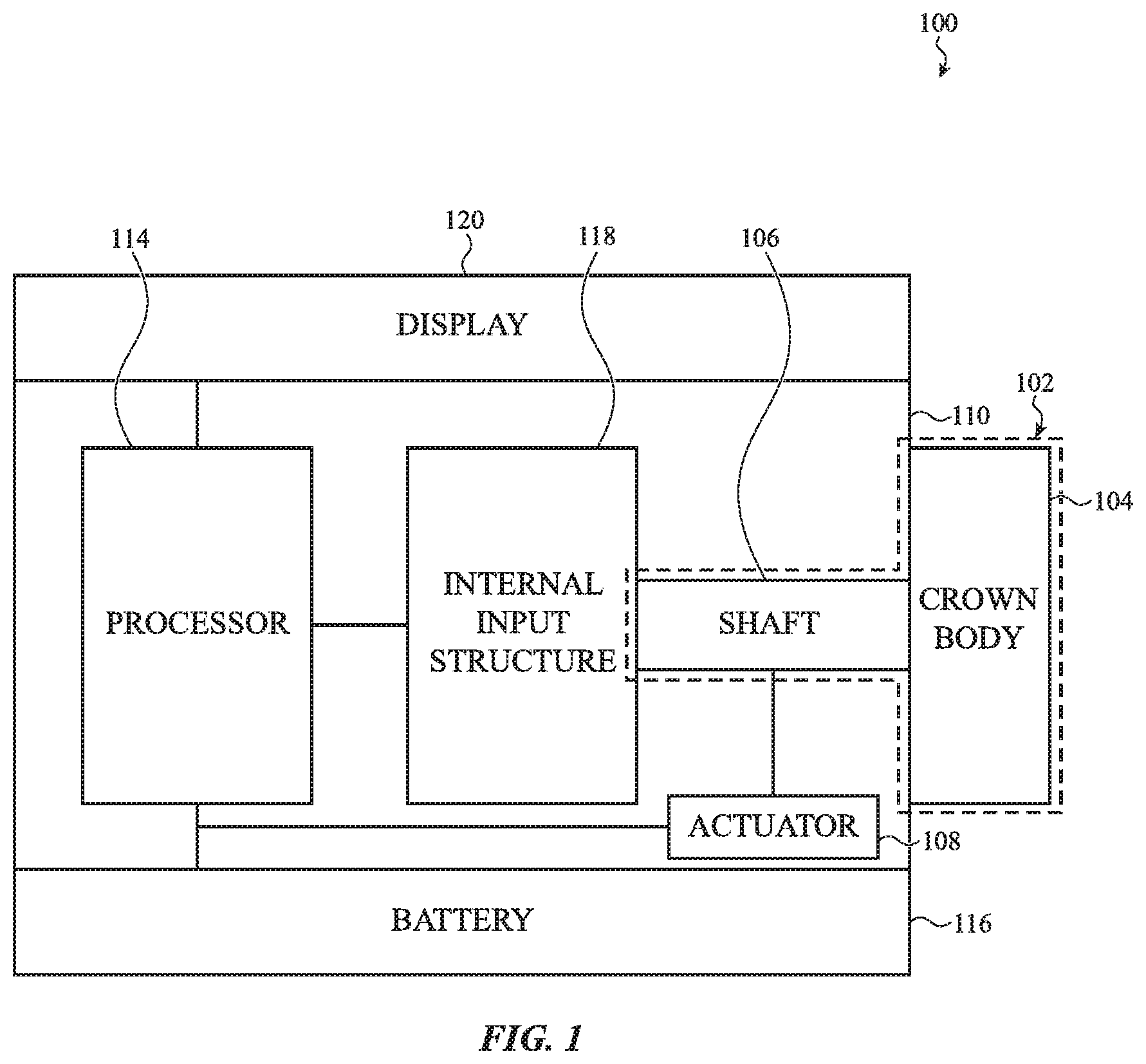
FIG. 1 is a block diagram of a sample electronic device 100 that includes an input mechanism 102 configured to provide multiple types of input in response to multiple types of input motion (such as rotation and translation of the input mechanism 102) as well as provide or otherwise transmit haptic output. That is, the input mechanism 102 may both accept input and provide output. In some embodiments, the electronic device 100 is an electronic smart watch and the input mechanism 102 is a crown. Other embodiments may take the form of different wearable devices, such as glasses, jewelry, clothing, and the like, portable computing devices (including tablets and personal digital assistants), laptop or desktop computers, mobile telephones, media players, and so on.
In addition to the input mechanism 102, the electronic device 100 generally includes a housing 110, a processing unit 114, a battery 116, and an actuator 108. The electronic device 100 may include a display 120, as well as an internal input structure 118. The display 120 typically is coupled to the housing 110. Operation of the various components of the electronic device 100 are described below.
In some embodiments, the input mechanism 102 may include, define, be made from, or otherwise incorporate two parts. One part may be external to the housing 110 while the second part may extend through the housing 110. For example, where the electronic device 100 is an electronic watch, the input mechanism 102 may be a crown with a crown body 104 and a shaft 106. The crown body 104 may be connected to, or formed integrally with, the shaft 106 and positioned so that the crown body 104 is outside a housing 110 of the electronic watch while the shaft 106 extends from the crown body 104, through the housing 110, and into an interior of the watch.
Generally, the crown may be used to provide multiple types of input to the electronic watch, including rotational input and translational input. For example, the crown 102 may be manipulated by a user to rotate or translate the crown body 104 and/or shaft 106 (e.g., to provide an input to the watch 100). The shaft 106 may be mechanically, electrically, magnetically, and/or optically coupled to components within the housing 110 that detect motion of the shaft 106 and/or crown body 104, whether rotational, translational, or both. Such components may generate an input in response to the motion of the shaft and/or crown body. As one non-limiting example, translating the crown 102 may close a switch within the housing 110, which may generate a first input. As another non-limiting example, rotating the crown 102 may be detected by an optical sensor, which may generate a second input.
In addition to rotational input and translational input, the crown 102 (or other input mechanism) may be touch-sensitive; a third input may be generated in response to a touch on the crown 102. The crown body 104 may be, function as, or incorporate an electrode to capacitively sense touch, as one example. The crown 102 may also use a thermal, optical, resistive, or other suitable type of sensor to detect touch on the crown body 104. In some embodiments, the crown 102 (and particularly the crown body 104) may function as one lead of an electrocardiogram ("ECG") sensor. Another electrode (e.g., lead) may be on, or part of, the housing 110 of the electronic device 100 or another external structure on the electronic device 100 and configured to come into contact with a user's skin. In further embodiments, multiple electrodes may be positioned on, or as part of, the housing 110 or another external structure and used as ECG leads.
A user input provided through the crown 102 may be used to manipulate or select various graphics displayed on the display 120, to adjust a volume of a speaker, to turn the watch 100 on or off, and so on. As another example, a user may use the crown 102 to initiate detection of a biological parameter such as a heart rate, electrocardiogram, or blood pressure. In response to an input on or through the crown 102, a display 120 of the electronic watch 100 may show a graphic representing the user's heart rate, blood pressure, or other biological parameter. Haptic output may be provided through a crown of the electronic watch in response to the input and/or displaying the graphic. Continuing the example, the haptic output may match a user's heartbeat. As another example, haptic output may signal a change in information displayed on the display 120.
Generally, a haptic output may be provided through the crown. For example, a haptic actuator may be attached to and/or operably coupled to the crown. As one non-limiting example, a haptic actuator may be operably coupled to the shaft 106, crown body 104, or other part of an input mechanism 102. The actuator 108 may generate haptic output in response to any of an input (which may be provided through the input mechanism 102, display 120, housing 110, or in another manner), output (such as a change in information on the display 120), change in operating status of the electronic device 100, change in state or status of software operated by the processing unit 114 or otherwise on the electronic device 100, receipt or transmission of a communication, a specific time or place being reached, a notification, and so on.
The actuator 108 may be physically coupled to the shaft 106 (or a shaft receiver, as discussed below), or may be operationally coupled thereto but physically decoupled from the shaft 106 (or shaft receiver). If physically coupled to the shaft 106, the actuator 108 may exert mechanical force on the shaft 106 to initiate haptic output through the crown 102. If physically decoupled from the shaft 106, the actuator 108 may use magnetic force to initiate haptic output through the crown 102, or may use electrostatics, ultrasonics, hydraulic pressure, hydrostatic pressure, or the like. The actuator 108 may be, for example, a piezoelectric actuator, a linear actuator or other mass driver, an electromagnet, a bladder, a pump, a piston, and so on. The exact structure of the actuator 108, its method of operation, and placement may vary from embodiment to embodiment.
In some embodiments, the electronic device 100 includes an internal input structure 118 configured to receive or otherwise detect motion of the crown 102 (or other input mechanism). The internal input structure 118 may be a switch that closes in response to the crown 102 translating, a sensor configured to sense the crown 102 rotating, a sensor configured to sense the crown 102 tilting, and so on. Sample sensors that may detect rotation and/or other motion of the crown 102 include optical sensors, capacitive sensors, mechanical sensors, electrical sensors, magnetic sensors, and so on. There may be multiple internal input structures 118 in a single electronic device 100.
A processing unit 114 is operably connected to the display 120, actuator 108, internal input structure 118 (if present), and/or crown 102. The processing unit 114 may receive input from an internal input structure 118 and/or directly from the crown 102, may control operation of the actuator 108 to provide haptic output through the crown 102, may control the display 120 to modify information displayed thereon, and generally operate various functions, features, and software of the electronic watch 100.
A battery 116 may provide power to the processing unit 114, actuator 108, display 120, internal input structure 118, and any other part of the smart electronic watch 100 (or other electronic device).
FIG. 2 illustrates a sample electronic device 100, here embodied as an electronic smart watch. The housing 110 may include a front-side housing member that faces away from a user's skin when the watch 100 is worn by a user, and a back-side housing member that faces toward the user's skin when worn. Alternatively, the housing 110 may be formed as a single member, or as more than two housing members. The one or more housing members may be metallic, plastic, ceramic, crystal, or other types of housing members (or combinations of such materials).
As discussed with respect to FIG. 1, a crown 102 may be manipulable to provide multiple types of input to the electronic watch 100 and may provide haptic output to a user touching the crown 102 (and particularly the crown body 104). The crown body 104 may be positioned such that a user may rotate the crown body 104 (and thus the shaft 106), may touch the crown body 104, and/or may exert force on the crown body 104 (for example, to move the crown body 104 towards the housing 110 or laterally with respect to the housing 110). Any or all of these actions may constitute user input.
The display 120 may include a cover attached to a housing 110 of the electronic device 100. The display 120 also may include a screen below the cover that is configured to display information, including graphics, symbols, text, and the like. The screen may be implemented as an OLED, LED, LCD, or any other suitable type of screen. The display 120 may be received at least partially within the housing 110.
The display 120 may be touch-sensitive and/or force-sensitive. The display 120 may be configured to depict a graphical output of the watch 100, and a user may interact with the graphical output (e.g., using a finger or stylus). As one example, the user may select (or otherwise interact with) a graphic, icon, or the like presented on the display by touching or pressing on the display at the location of the graphic. The cover (e.g., outer surface of the display 120) may form a part of or be attached to the housing 110. In some examples, the cover may be crystal, such as a sapphire crystal. The cover may alternatively be formed of glass, plastic, or other materials. The cover may be transparent or translucent to some or all wavelengths of electromagnetic radiation, including visible light. In some embodiments, the actuator 108 may provide haptic output through the display 120 and associated cover instead of, or in addition to, through the crown 102.
The housing 110 may also include an aperture through which a button 200 protrudes. The button 200 may likewise be used to provide input to the electronic device 100. In some embodiments, the button 200 may provide haptic output in addition to, or instead of, the crown 102. Thus, the description herein regarding providing haptic output through (e.g., transmitted by, through, or along) the crown 102 applies equally to haptic output through the button 200.
The electronic watch 100 may include a band 204, which may be removably attached to the housing 110. The housing 110 may include structures for attaching the watch band 204 to the watch body. In some cases, the structures may include elongate recesses or apertures through which ends of the watch band 204 may be inserted and attached to the watch housing 110. In other cases (not shown), the structures may include indents (e.g., dimples or depressions) in the housing 110, which indents may receive ends of spring pins that are attached to or threaded through ends of a watch band to attach the watch band to the watch body.
In some examples, the watch 100 may lack the display 120 (and/or its cover), the crown 102, or the button 200. For example, the watch 100 may include an audio input or output interface, a touch input interface, an output interface, or other input or output interface that does not require the display 120, crown 102, or button 200. The watch 100 may also include the afore-mentioned input or output interfaces in addition to the display 120, crown 102, or button 200. When the watch 100 lacks the display 120, the front side of the watch 100 may be covered by a housing member that is opaque.
FIG. 3A is a cross-sectional view of the crown 102 taken along line 3-3 of FIG. 2. As shown, the crown 102 includes a crown body 104 and shaft 106. The crown body 104 and shaft 106 are shown as integrally formed with one another, although in other embodiments they may be separate pieces attached to one another. Further, either or both of the crown body 104 and shaft 106 may be formed from multiple separate pieces.
The shaft 106 extends through the housing 110, and specifically through a collar 300 attached to the housing 110. The collar 300 may be configured to reduce and/or prevent tilting of the shaft 106, although in some embodiments the collar 300 may permit the shaft to tilt to a certain extent. The collar 300 may also electrically insulate the shaft 106 from the housing 110. A set of O-rings 302 or other seals prevent water, dust, and the like from entering an interior of the housing 110 along the shaft 106.
A shaft receiver 304 is attached to an end of the shaft 106; some embodiments may omit the shaft receiver 304 and/or collar 300. The shaft receiver 304 generally moves with the shaft 106 while the collar 300 does not. The shaft receiver 304 may be patterned, marked, or otherwise configured to reflect light as it rotates. A sensor 308 (which is one example of an internal input structure 118) may emit light toward the shaft receiver 304 and receive light reflected from the shaft receiver 304. As the shaft rotates, the amount, pattern, intensity, or other parameter of the light reflected by the shaft 106 (and received by the optical sensor 308) may change. Such changes may be cause the sensor 308 to output an input signal that may be correlated to a speed and/or amount of rotation by the sensor 308 or by an associated processing unit 114.
A switch 310 is positioned adjacent or near an end of the shaft 106 or shaft receiver 304 (if present). As the shaft 106 translates towards the housing 110, the shaft receiver 304 may collapse or close the switch 310. The switch 310, in turn, generates an input signal indicating the crown 102 has been pressed. In some embodiments, the switch 310 may be separated from the shaft receiver 304 and/or shaft 106 by a shear plate, membrane, or other structure configured to permit the switch 310 to close in response to the crown 102 translating, but prevent the switch 310 from wearing down as the crown 102 (and thus shaft receiver 304) rotates.
The crown body 104 may be rotated about an axis of rotation by a user. Such rotation likewise rotates the shaft 106 and shaft receiver 304, but typically does not cause the collar 300 to rotate (although it may in some embodiments). Generally, the axis about which the crown body 104 and shaft 106 rotates extends through a center of the crown body 104 and shaft 106. The crown body 104 and shaft 106 also translate along this axis of rotation, in certain embodiments.
An internal support 306 supports, and is attached to, the switch 310, sensor 308, and optionally the actuator 108. In some embodiments, different internal supports may be used for each or any of the switch 310, sensor 308, and actuator 108. For example, the actuator 108 may be attached directly to the housing 110.
The actuator 108 may be physically coupled to the shaft 106 (or shaft receiver 304), or may be operationally coupled thereto but physically decoupled from the shaft 106 (or shaft receiver 304). If physically coupled to the shaft 106, the actuator 108 may exert mechanical force on the shaft to initiate haptic output through the crown 102. If physically decoupled from the shaft 106, the actuator 108 may use electromagnetic force to initiate haptic output through the crown 102, or may use electrostatics, ultrasonics, hydraulic pressure, hydrostatic pressure, or the like. The actuator 108 may be, for example, a piezoelectric actuator, a linear actuator or other mass driver, an electromagnet, a bladder, a pump, a piston, and so on. The exact structure of the actuator 108, its method of operation, and placement may vary from embodiment to embodiment. In many embodiments, the actuator 108 provides haptic output to or through the crown 102 in response to an input provided to or through the crown 102. For example, rotating the crown 102 may cause the actuator 108 to provide an output, as may pressing the crown. It should be appreciated that each type or mode may cause the actuator 108 to provide a different haptic output, at least in some embodiments. In other embodiments, two or more input types or modes can trigger the same haptic output, although multiple types of haptic output may still be provided.
The crown body 104 is separated from the housing 110 by a gap 312. FIG. 3A illustrates the gap 312 in a nominal or default state (e.g., one where no input force or haptic output force is exerted on the crown 102).
By contrast, FIG. 3B illustrates the crown 102 when a force moves the crown body 104 toward the housing 110. In some embodiments the actuator 108 may pull the crown body 104 toward the housing 110, thereby narrowing the gap 312 as shown in FIG. 3B. The motion of the crown body 104 may be perceived by a person touching the crown body 104 as a haptic output.
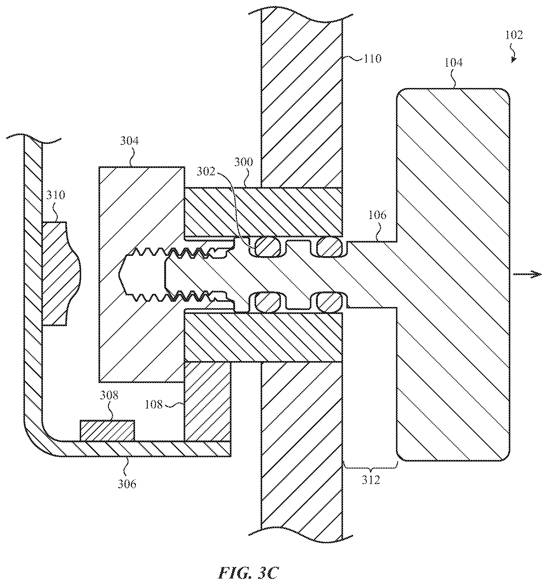
As another option, the actuator 108 may move the crown 102 outward, such that the crown body 104 moves away from the housing 110. FIG. 3C illustrates the crown 102 undergoing such haptic output. Here, the actuator 108 exerts an outward force on the shaft 106 (or crown body 104, depending on the positioning of the actuator 108 within or outside the housing 110) such that the gap 312 increases. The maximum distance the crown body 104 may travel (and thus the size of the gap 312) may be set by the distance between the shaft receiver 304 (or another structural element, such as a plate, ledge, projection, protrusion, or the like) and the collar 300 (or the housing 110) when the crown 102 is in its rest state. In some embodiments, the actuator 108 may move the crown body 104 away from the housing 110 in response to a user providing an input, such as pressing the crown 102 toward the housing 110.
FIG. 3D illustrates yet another type of haptic output provided through the crown 102 by the actuator 108. Here, the actuator 108 rotates the shaft 106 and crown body 104 about the crown's axis of rotation. A user touching the crown body 104 may feel its rotation, which may stretch or shear the user's skin contacting the crown body 104. This is a third type of haptic output that may be provided by the actuator 108 through the crown 102.
As previously mentioned, haptic output may take the form of stopping crown 102 motion as well as moving the crown 102. For example, the actuator 108 may periodically stop or slow rotation of the crown body 104 by braking the shaft 106 or crown body 104. This change in rotational speed may be perceived by the user as yet another type of haptic output, for example in response to a rotational input. Similarly, the actuator 108 may accelerate rotation of the crown 102 to provide yet another type of haptic output. The actuator 108 may be configured to stop, slow, pause, and/or accelerate translation motion of the crown 102, as well, as yet more examples of haptic output.
In some embodiments, the actuator 108 may move, shake, vibrate, or otherwise impact the housing 110 in addition to the crown 102 when providing haptic output. An electronic watch 100 or other device may incorporate multiple actuators 108, such that one acts on the housing 110 while another acts on the crown 102. Yet another actuator 108 may act on the display 120. In still other embodiments, a single actuator 108 is used and the waveform produced by the actuator 108 is tuned to channel a majority of the actuator's force through the crown 102 rather than the housing 110, thereby ensuring a majority of the haptic output passes through or along the crown 102. In yet other embodiments, the actuator 108 is configured to move the crown 102 more than the housing 110 even though the housing 110 may be subjected to as much or more of the actuator's force than the crown 102.
As discussed above, graphics displayed on the electronic devices herein may be manipulated through inputs provided to a crown. FIGS. 4A-4B generally depict examples of changing a graphical output displayed on an electronic device through inputs provided by force and/or rotational inputs to a crown assembly of the device. This manipulation (e.g., selection, acknowledgement, motion, dismissal, magnification, and so on) of a graphic, through inputs to the crown, may result in changes in operation of the electronic device and/or graphical output displayed by the electronic device. Although specific examples are provided and discussed, many operations may be performed by rotating and/or applying force to a crown such as the examples described above. Accordingly, the following discussion is by way of example and not limitation. Haptic output may be generated by an actuator 108 and transmitted through a crown 402 in response to any of the changes in output discussed herein. Further, insofar as the actuator 108 may provide haptic output in response to the same input that results in changes in graphical output on the display, the changes in graphical output and haptic output may occur substantially simultaneously. "Substantially simultaneously" generally means sufficiently close in time together that a user perceives the two as occurring at the same time, or, in some embodiments, within about 1-20 milliseconds of one another, or 1-150 milliseconds of one another in still other embodiments.
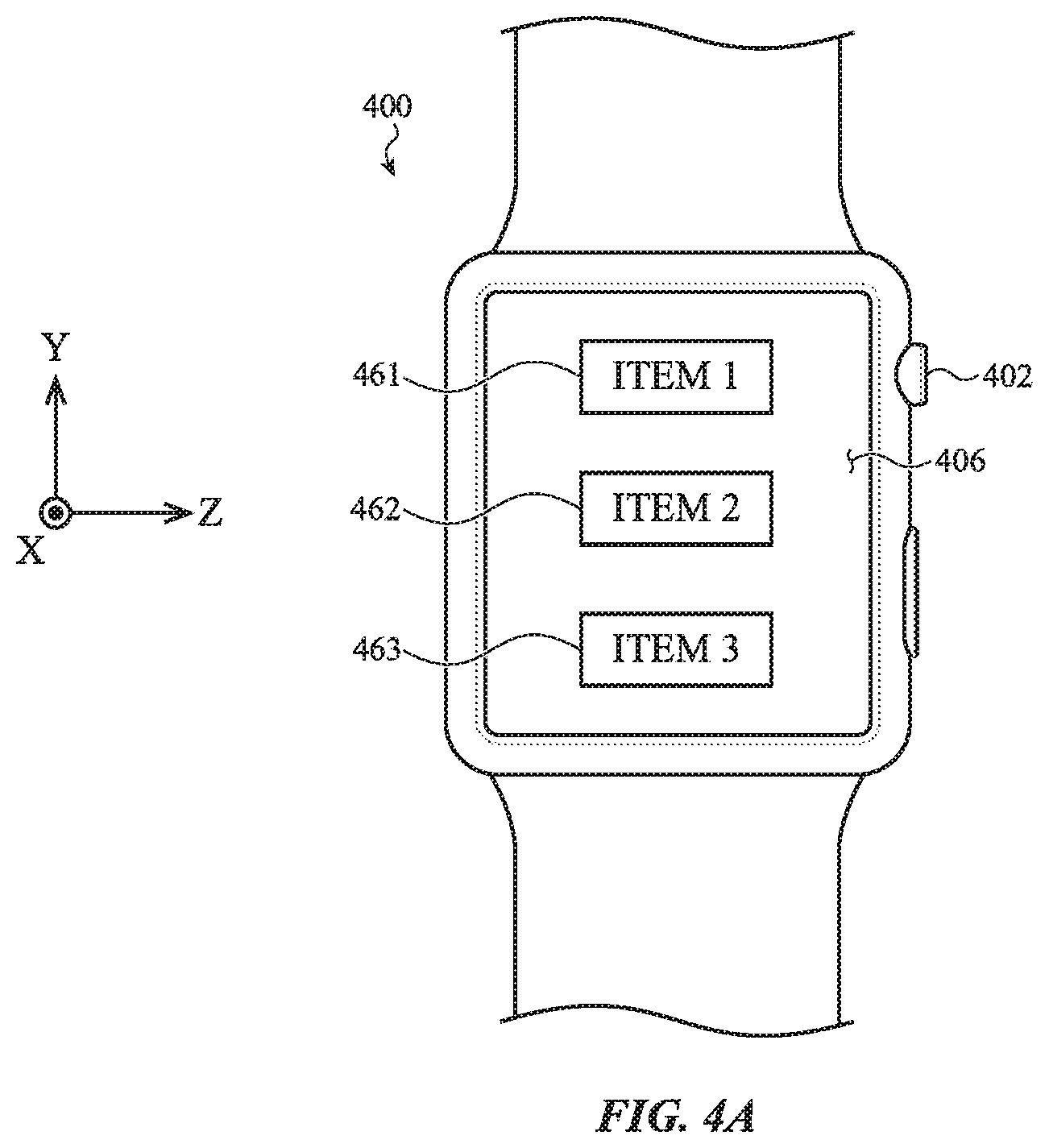
FIG. 4A depicts an example electronic device 400 (shown here as an electronic watch) having a crown 402. The crown 402 may be similar to the examples described above, and may receive force inputs along a first lateral direction, a second lateral direction, or an axial direction of the crown. The crown 402 may also receive rotational inputs. A display 406 provides a graphical output (e.g., shows information and/or other graphics). In some embodiments, the display 406 may be configured as a touch-sensitive display capable of receiving touch and/or force input. In the current example, the display 406 depicts a list of various items 461, 462, 463, all of which are example graphical outputs.
FIG. 4B illustrates how the graphical output shown on the display 406 changes as the crown 402 rotates, partially or completely (as indicated by the arrow 460). Rotating the crown 402 causes the list to scroll or otherwise move on the screen, such that the first item 461 is no longer displayed, the second and third items 462, 463 each move upwards on the display, and a fourth item 464 is now shown at the bottom of the display 406. This is one example of a scrolling operation that can be executed by rotating the crown 402. Such scrolling operations may provide a simple and efficient way to depict multiple items relatively quickly and in sequential order. In some examples, the items may be used to trigger various aspects of the optical sensor subsystems described herein, or to select various outputs of the optical sensor subsystems for further review. A speed of the scrolling operation may be controlled by the amount of rotational force applied to the crown 402 and/or the speed at which the crown 402 is rotated. Faster or more forceful rotation may yield faster scrolling, while slower or less forceful rotation yields slower scrolling. In some embodiments, rotation of the crown causes not only scrolling of the graphical output but also haptic output simulating one or more detents as the crown rotates, as discussed above.
The crown 402 may receive an axial force (e.g., a force inward toward the display 406 or watch body) to select an item from the list, in certain embodiments. Likewise, faster or more forceful rotation (or translation) of a crown 402 may yield faster or harder haptic output through the crown 402, while slower or less forceful rotation or translation yields slower or less forceful haptic output. Put another way, haptic output transmitted through the crown may vary to match a parameter of an input or other output, such as speed, force, magnitude, and the like.
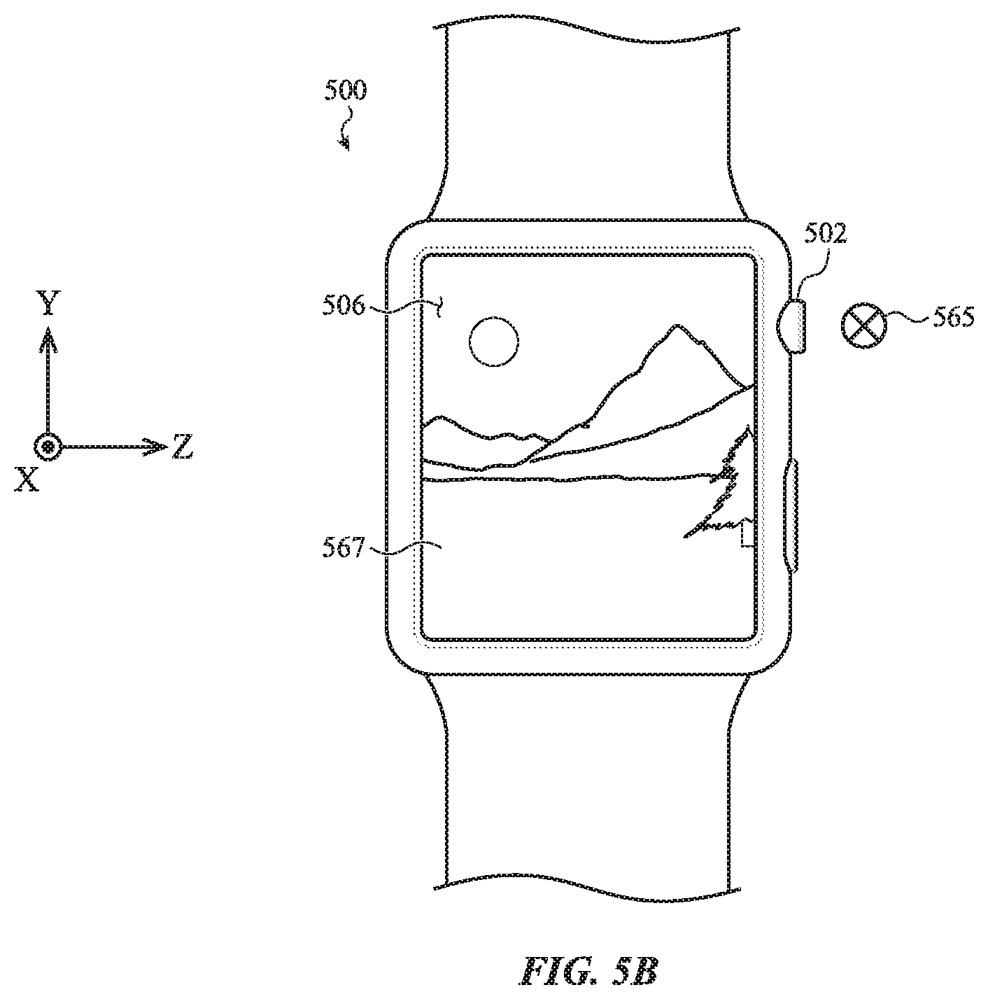
FIGS. 5A and 5B illustrate an example zoom operation; haptic output may be provided through a crown as the zoom operation is carried out. The display 506 depicts a picture 566 at a first magnification, shown in FIG. 5A; the picture 566 is yet another example of an indicium. A user may apply a lateral force (e.g., a force along the x-axis) to the crown 502 of the electronic device 500 (illustrated by arrow 565), and in response the display 506 may zoom into the picture 566, such that a portion 567 of the picture is shown at an increased magnification. This is shown in FIG. 5B. The direction of zoom (in vs. out) and speed of zoom, or location of zoom, may be controlled through force applied to the crown 502, and particularly through the direction of applied force and/or magnitude of applied force. Applying force to the crown 502 in a first direction may zoom in, while applying force to the crown 502 in an opposite direction may zoom out. Alternately, rotating or applying force to the crown 502 in a first direction may change the portion of the picture subject to the zoom effect. In some embodiments, applying an axial force (e.g., a force along the z-axis) to the crown 502 may toggle between different zoom modes or inputs (e.g., direction of zoom vs. portion of picture subject to zoom). In yet other embodiments, applying force to the crown 502 along another direction, such as along the y-axis, may return the picture 566 to the default magnification shown in FIG. 5A.
FIGS. 6A and 6B illustrate possible use of the crown 602 to change an operational state of the electronic device 600 or otherwise toggle between inputs; haptic output may be provided through the crown 602 in response to such changes or toggles. Turning first to FIG. 6A, the display 606 depicts a question 668, namely, "Would you like directions?" As shown in FIG. 6B, a lateral force may be applied to the crown 602 (illustrated by arrow 670) to answer the question. Applying force to the crown 602 provides an input interpreted by the electronic device 600 as "yes," and so "YES" is displayed as a graphic 669 on the display 606. Applying force to the crown 602 in an opposite direction may provide a "no" input. Both the question 668 and graphic 669 are examples of graphical outputs. As one non-limiting example, a graphic or other information (such as a map or list of directions) may be shown on the display 606 in response to the user selecting "YES," for example by rotating, translating, or touching the crown 602. Haptic output may be provided through the crown 602 and linked to the displayed information; as one example, haptic output may be provided through the crown 602 whenever a user approaches a turn or other change in route or next step in the list of directions.
In the embodiment shown in FIGS. 6A and 6B, the force applied to the crown 602 is used to directly provide the input, rather than select from options in a list (as discussed above with respect to FIGS. 4A and 4B).
As mentioned previously, force or rotational input to a crown of an electronic device may control many functions beyond those listed here. The crown may receive distinct force or rotational inputs to adjust a volume of an electronic device, a brightness of a display, or other operational parameters of the device. A force or rotational input applied to the crown may rotate to turn a display on or off, or turn the device on or off. A force or rotational input to the crown may launch or terminate an application on the electronic device. Further, combinations of inputs to the crown may likewise initiate or control any of the foregoing functions, as well.
In some cases, the graphical output of a display may be responsive to inputs applied to a touch-sensitive display (e.g., displays 406, 506, 606, and the like) in addition to inputs applied to a crown. The touch-sensitive display may include or be associated with one or more touch and/or force sensors that extend along an output region of a display and which may use any suitable sensing elements and/or sensing techniques to detect touch and/or force inputs applied to the touch-sensitive display. The same or similar graphical output manipulations that are produced in response to inputs applied to the crown may also be produced in response to inputs applied to the touch-sensitive display. For example, a swipe gesture applied to the touch-sensitive display may cause the graphical output to move in a direction corresponding to the swipe gesture. As another example, a tap gesture applied to the touch-sensitive display may cause an item to be selected or activated. In this way, a user may have multiple different ways to interact with and control an electronic watch, and in particular the graphical output of an electronic watch. Further, while the crown may provide overlapping functionality with the touch-sensitive display, using the crown allows for the graphical output of the display to be visible (without being blocked by the finger that is providing the touch input). Likewise, an actuator may produce haptic output in response to an input to or through the crown.
FIG. 7 shows a sample electrical block diagram of an electronic device 700, which electronic device may in some cases take the form of any of the watches or other wearable electronic devices described herein, or other portable or wearable electronic devices. The electronic device 700 can include a display 705 (e.g., a light-emitting display), a processing unit 710, a power source 715, a memory 720 or storage device, a sensor 725, and an input/output (I/O) mechanism 730 (e.g., an input/output device, input/output port, or haptic input/output interface such as an actuator 108 and/or crown 102, or the combination thereof). The processing unit 710 can control some or all of the operations of the electronic device 700. The processing unit 710 can communicate, either directly or indirectly, with some or all of the components of the electronic device 700. For example, a system bus or other communication mechanism 735 can provide communication between the processing unit 710, the power source 715, the memory 720, the sensor 725, and the input/output mechanism 730.
The processing unit 710 can be implemented as any electronic device capable of processing, receiving, or transmitting data or instructions. For example, the processing unit 710 can be a microprocessor, a central processing unit (CPU), an application-specific integrated circuit (ASIC), a digital signal processor (DSP), or combinations of such devices. As described herein, the term "processing unit" is meant to encompass a single processor or processing unit, multiple processors, multiple processing units, or other suitably configured computing element or elements.
It should be noted that the components of the electronic device 700 can be controlled by multiple processing units. For example, select components of the electronic device 700 (e.g., a sensor 725) may be controlled by a first processing unit and other components of the electronic device 700 (e.g., the display 705) may be controlled by a second processing unit, where the first and second processing units may or may not be in communication with each other.
The power source 715 can be implemented with any device capable of providing energy to the electronic device 700. For example, the power source 715 may be one or more batteries or rechargeable batteries. Additionally or alternatively, the power source 715 can be a power connector or power cord that connects the electronic device 700 to another power source, such as a wall outlet.
The memory 720 can store electronic data that can be used by the electronic device 700. For example, the memory 720 can store electrical data or content such as, for example, audio and video files, documents and applications, device settings and user preferences, timing signals, control signals, and data structures or databases. The memory 720 can be configured as any type of memory. By way of example only, the memory 720 can be implemented as random access memory, read-only memory, Flash memory, removable memory, other types of storage elements, or combinations of such devices.
The electronic device 700 may also include one or more sensors 725 positioned almost anywhere on the electronic device 700. The sensor(s) 725 can be configured to sense one or more type of parameters, such as but not limited to, pressure, light, touch, heat, movement, relative motion, biometric data (e.g., biological parameters), and so on. For example, the sensor(s) 725 may include a heat sensor, a position sensor, a light or optical sensor, an accelerometer, a pressure transducer, a gyroscope, a magnetometer, a health monitoring sensor, and so on. Additionally, the one or more sensors 725 can utilize any suitable sensing technology, including, but not limited to, capacitive, ultrasonic, resistive, optical, ultrasound, piezoelectric, and thermal sensing technology.
The I/O mechanism 730 can transmit and/or receive data from a user or another electronic device. An I/O device can include a display, a touch sensing input surface, one or more buttons (e.g., a graphical user interface "home" button), one or more cameras, one or more microphones or speakers, one or more ports such as a microphone port, and/or a keyboard. Additionally or alternatively, an I/O device or port can transmit electronic signals via a communications network, such as a wireless and/or wired network connection. Examples of wireless and wired network connections include, but are not limited to, cellular, Wi-Fi, Bluetooth, IR, and Ethernet connections.
The foregoing description, for purposes of explanation, uses specific nomenclature to provide a thorough understanding of the described embodiments. However, it will be apparent to one skilled in the art that the specific details are not required in order to practice the described embodiments. Thus, the foregoing descriptions of the specific embodiments described herein are presented for purposes of illustration and description. They are not targeted to be exhaustive or to limit the embodiments to the precise forms disclosed. It will be apparent to one of ordinary skill in the art that many modifications and variations are possible in view of the above teachings.
* * * * *
References
D00000
D00001
D00002
D00003
D00004
D00005
D00006
D00007
D00008
D00009
D00010
D00011
D00012

D00013

XML
uspto.report is an independent third-party trademark research tool that is not affiliated, endorsed, or sponsored by the United States Patent and Trademark Office (USPTO) or any other governmental organization. The information provided by uspto.report is based on publicly available data at the time of writing and is intended for informational purposes only.
While we strive to provide accurate and up-to-date information, we do not guarantee the accuracy, completeness, reliability, or suitability of the information displayed on this site. The use of this site is at your own risk. Any reliance you place on such information is therefore strictly at your own risk.
All official trademark data, including owner information, should be verified by visiting the official USPTO website at www.uspto.gov. This site is not intended to replace professional legal advice and should not be used as a substitute for consulting with a legal professional who is knowledgeable about trademark law.