Anti-pinch control system for powered vehicle doors
Khan , et al. March 2, 2
U.S. patent number 10,934,760 [Application Number 16/395,612] was granted by the patent office on 2021-03-02 for anti-pinch control system for powered vehicle doors. This patent grant is currently assigned to Ford Global Technologies, LLC. The grantee listed for this patent is Ford Global Technologies, LLC. Invention is credited to George Anthony Bernwanger, Jr., Muhammad Omer Khan, H. Paul Tsvi Linden, Kosta Papanikolaou, Christopher Matthew Radjewski.


View All Diagrams
| United States Patent | 10,934,760 |
| Khan , et al. | March 2, 2021 |
Anti-pinch control system for powered vehicle doors
Abstract
A vehicle includes a body and front and rear doors having front and rear powered latches, front and rear anti-pinch sensors, and front and rear electrically-powered door openers. The vehicle further includes a controller that is configured to receive an unlatch signal from unlatch sensors/switches and generate a signal to unlatch the front and rear powered latches and actuate the front and rear door openers after the front and rear powered latches are unlatched. The controller may also be configured to actuate the rear door opener to retain the rear door in an open position when the front pinch sensor detects a hand to thereby prevent pinching.
| Inventors: | Khan; Muhammad Omer (Markham, CA), Papanikolaou; Kosta (Huntington Woods, MI), Radjewski; Christopher Matthew (Macomb, MI), Linden; H. Paul Tsvi (Southfield, MI), Bernwanger, Jr.; George Anthony (Northville, MI) | ||||||||||
|---|---|---|---|---|---|---|---|---|---|---|---|
| Applicant: |
|
||||||||||
| Assignee: | Ford Global Technologies, LLC
(Dearborn, MI) |
||||||||||
| Family ID: | 60020815 | ||||||||||
| Appl. No.: | 16/395,612 | ||||||||||
| Filed: | April 26, 2019 |
Prior Publication Data
| Document Identifier | Publication Date | |
|---|---|---|
| US 20190249475 A1 | Aug 15, 2019 | |
Related U.S. Patent Documents
| Application Number | Filing Date | Patent Number | Issue Date | ||
|---|---|---|---|---|---|
| 15245622 | Aug 24, 2016 | 10329823 | |||
| Current U.S. Class: | 1/1 |
| Current CPC Class: | B60J 5/047 (20130101); E05F 15/44 (20150115); E05F 5/00 (20130101); E05F 15/611 (20150115); E05F 15/46 (20150115); E05F 15/60 (20150115); E05F 15/42 (20150115); E05Y 2201/232 (20130101); E05Y 2800/41 (20130101); E05Y 2900/531 (20130101); E05Y 2400/20 (20130101); E05Y 2400/54 (20130101); E05F 15/43 (20150115); E05Y 2201/22 (20130101); E05Y 2201/40 (20130101); E05Y 2201/426 (20130101); E05Y 2400/44 (20130101) |
| Current International Class: | B60J 5/00 (20060101); E05F 5/00 (20170101); B60J 5/04 (20060101); E05F 15/60 (20150101); E05F 15/46 (20150101); E05F 15/611 (20150101); E05F 15/44 (20150101); E05F 15/42 (20150101); E05F 15/43 (20150101) |
References Cited [Referenced By]
U.S. Patent Documents
| 2229909 | January 1941 | Wread |
| 2553023 | May 1951 | Walters |
| 3479767 | November 1969 | Gardner et al. |
| 3605459 | September 1971 | Van Dalen |
| 3751718 | August 1973 | Hanchett |
| 3771823 | November 1973 | Schnarr |
| 3854310 | December 1974 | Paull |
| 3858922 | January 1975 | Yamanaka |
| 4193619 | March 1980 | Jeril |
| 4206491 | June 1980 | Ligman et al. |
| 4425597 | January 1984 | Schramm |
| 4457148 | July 1984 | Johansson et al. |
| 4640050 | February 1987 | Yamagishi et al. |
| 4672348 | June 1987 | Duve |
| 4674230 | June 1987 | Takeo et al. |
| 4674781 | June 1987 | Reece et al. |
| 4702117 | October 1987 | Tsutsumi et al. |
| 4848031 | June 1989 | Yamagishi et al. |
| 4858971 | August 1989 | Haag |
| 4889373 | December 1989 | Ward et al. |
| 4929007 | May 1990 | Bartczak et al. |
| 5018057 | May 1991 | Biggs et al. |
| 5056343 | October 1991 | Kleefeldt et al. |
| 5058258 | October 1991 | Harvey |
| 5074073 | December 1991 | Zwebner |
| 5092637 | March 1992 | Miller |
| 5173991 | December 1992 | Carswell |
| 5239779 | August 1993 | Deland et al. |
| 5263762 | November 1993 | Long et al. |
| 5297010 | March 1994 | Camarota et al. |
| 5332273 | July 1994 | Komachi |
| 5334969 | August 1994 | Abe et al. |
| 5494322 | February 1996 | Menke |
| 5497641 | March 1996 | Linde et al. |
| 5535608 | July 1996 | Brin |
| 5547208 | August 1996 | Chappell et al. |
| 5551187 | September 1996 | Brouwer et al. |
| 5581230 | December 1996 | Barrett |
| 5583405 | December 1996 | Sai et al. |
| 5613716 | March 1997 | Cafferty |
| 5618068 | April 1997 | Mitsui et al. |
| 5632120 | May 1997 | Shigematsu et al. |
| 5632515 | May 1997 | Dowling |
| 5644869 | July 1997 | Buchanan, Jr. |
| 5653484 | August 1997 | Brackmann et al. |
| 5662369 | September 1997 | Tsuge |
| 5684470 | November 1997 | DeLand et al. |
| 5744874 | April 1998 | Yoshida et al. |
| 5755059 | May 1998 | Schap |
| 5783994 | July 1998 | Koopman, Jr. et al. |
| 5802894 | September 1998 | Jahrsetz et al. |
| 5808555 | September 1998 | Bartel |
| 5852944 | December 1998 | Collard, Jr. et al. |
| 5859417 | January 1999 | David |
| 5895089 | April 1999 | Singh et al. |
| 5896026 | April 1999 | Higgins |
| 5896768 | April 1999 | Cranick et al. |
| 5898536 | April 1999 | Won |
| 5901991 | May 1999 | Hugel et al. |
| 5921612 | July 1999 | Mizuki et al. |
| 5927794 | July 1999 | Mobius |
| 5964487 | October 1999 | Shamblin |
| 5979754 | November 1999 | Martin et al. |
| 5992194 | November 1999 | Baukholt et al. |
| 6000257 | December 1999 | Thomas |
| 6027148 | February 2000 | Shoemaker |
| 6038895 | March 2000 | Menke et al. |
| 6042159 | March 2000 | Spitzley et al. |
| 6043735 | March 2000 | Barrett |
| 6050117 | April 2000 | Weyerstall |
| 6056076 | May 2000 | Bartel et al. |
| 6065316 | May 2000 | Sato et al. |
| 6072403 | June 2000 | Iwasaki et al. |
| 6075294 | June 2000 | Van den Boom et al. |
| 6075298 | June 2000 | Maue et al. |
| 6089626 | July 2000 | Shoemaker |
| 6091162 | July 2000 | Williams, Jr. et al. |
| 6099048 | August 2000 | Salmon et al. |
| 6125583 | October 2000 | Murray et al. |
| 6130614 | October 2000 | Miller |
| 6145918 | November 2000 | Wilbanks, II |
| 6157090 | December 2000 | Vogel |
| 6181024 | January 2001 | Geil |
| 6198995 | March 2001 | Settles et al. |
| 6241294 | June 2001 | Young et al. |
| 6247343 | June 2001 | Weiss et al. |
| 6256932 | July 2001 | Jyawook et al. |
| 6271745 | August 2001 | Anazi et al. |
| 6305737 | October 2001 | Corder et al. |
| 6341448 | January 2002 | Murray |
| 6357803 | March 2002 | Lorek |
| 6361091 | March 2002 | Weschler |
| 6405485 | June 2002 | Itami et al. |
| 6406073 | June 2002 | Watanabe |
| 6441512 | August 2002 | Jakel et al. |
| 6460905 | October 2002 | Suss |
| 6470719 | October 2002 | Franz et al. |
| 6480098 | November 2002 | Flick |
| 6481056 | November 2002 | Jesse |
| 6515377 | February 2003 | Uberlein et al. |
| 6523376 | February 2003 | Baukholt et al. |
| 6550826 | April 2003 | Fukushima et al. |
| 6554328 | April 2003 | Cetnar et al. |
| 6556900 | April 2003 | Brynielsson |
| 6602077 | August 2003 | Kasper et al. |
| 6606492 | August 2003 | Losey |
| 6629711 | October 2003 | Gleason et al. |
| 6639161 | October 2003 | Meagher et al. |
| 6657537 | December 2003 | Hauler |
| 6659515 | December 2003 | Raymond et al. |
| 6701671 | March 2004 | Fukumoto et al. |
| 6712409 | March 2004 | Monig |
| 6715806 | April 2004 | Arlt et al. |
| 6734578 | May 2004 | Konno et al. |
| 6740834 | May 2004 | Sueyoshi et al. |
| 6768413 | July 2004 | Kemmann et al. |
| 6779372 | August 2004 | Arlt et al. |
| 6783167 | August 2004 | Bingle et al. |
| 6786070 | September 2004 | Dimig et al. |
| 6794837 | September 2004 | Whinnery et al. |
| 6825752 | November 2004 | Nahata et al. |
| 6829357 | December 2004 | Alrabady et al. |
| 6843085 | January 2005 | Dimig |
| 6854870 | February 2005 | Huizenga |
| 6879058 | April 2005 | Lorenz et al. |
| 6883836 | April 2005 | Breay et al. |
| 6883839 | April 2005 | Belmond et al. |
| 6910302 | June 2005 | Crawford |
| 6914346 | July 2005 | Girard |
| 6923479 | August 2005 | Aiyama et al. |
| 6933655 | August 2005 | Morrison et al. |
| 6948978 | September 2005 | Schofield |
| 7005959 | February 2006 | Amagasa |
| 7038414 | May 2006 | Daniels et al. |
| 7055997 | June 2006 | Baek |
| 7062945 | June 2006 | Saitoh et al. |
| 7070018 | July 2006 | Kachouh |
| 7070213 | July 2006 | Willats et al. |
| 7090285 | August 2006 | Markevich et al. |
| 7091823 | August 2006 | Ieda et al. |
| 7091836 | August 2006 | Kachouh et al. |
| 7097226 | August 2006 | Bingle et al. |
| 7106171 | September 2006 | Burgess |
| 7108301 | September 2006 | Louvel |
| 7126453 | October 2006 | Sandau et al. |
| 7145436 | December 2006 | Ichikawa et al. |
| 7161152 | January 2007 | Dipoala |
| 7163221 | January 2007 | Leitner |
| 7170253 | January 2007 | Spurr et al. |
| 7173346 | February 2007 | Aiyama et al. |
| 7176810 | February 2007 | Inoue |
| 7180400 | February 2007 | Amagasa |
| 7192076 | March 2007 | Ottino |
| 7204530 | April 2007 | Lee |
| 7205777 | April 2007 | Schultz et al. |
| 7221255 | May 2007 | Johnson et al. |
| 7222459 | May 2007 | Taniyama |
| 7248955 | July 2007 | Hein et al. |
| 7263416 | August 2007 | Sakurai et al. |
| 7270029 | September 2007 | Papanikolaou et al. |
| 7325843 | February 2008 | Coleman et al. |
| 7342373 | March 2008 | Newman et al. |
| 7360803 | April 2008 | Parent et al. |
| 7363788 | April 2008 | Dimig et al. |
| 7375299 | May 2008 | Pudney |
| 7399010 | July 2008 | Hunt et al. |
| 7446656 | November 2008 | Steegmann |
| 7576631 | August 2009 | Bingle et al. |
| 7642669 | January 2010 | Spurr |
| 7686378 | March 2010 | Gisler et al. |
| 7688179 | March 2010 | Kurpinski et al. |
| 7705722 | April 2010 | Shoemaker et al. |
| 7747286 | June 2010 | Conforti |
| 7780207 | August 2010 | Gotou et al. |
| 7791218 | September 2010 | Mekky et al. |
| 7926385 | April 2011 | Papanikolaou et al. |
| 7931314 | April 2011 | Nitawaki et al. |
| 7937893 | May 2011 | Pribisic |
| 8028375 | October 2011 | Nakaura et al. |
| 8093987 | January 2012 | Kurpinski et al. |
| 8126450 | February 2012 | Howarter et al. |
| 8141296 | March 2012 | Bern |
| 8141916 | March 2012 | Tomaszewski et al. |
| 8169317 | May 2012 | Lemerand et al. |
| 8193462 | June 2012 | Zanini et al. |
| 8224313 | July 2012 | Howarter et al. |
| 8228077 | July 2012 | Wuerstlein et al. |
| 8272165 | September 2012 | Tomioka |
| 8376416 | February 2013 | Arabia, Jr. et al. |
| 8398128 | March 2013 | Arabia et al. |
| 8405515 | March 2013 | Ishihara et al. |
| 8405527 | March 2013 | Chung et al. |
| 8419114 | April 2013 | Fannon |
| 8451087 | May 2013 | Krishnan et al. |
| 8454062 | June 2013 | Rohlfing et al. |
| 8474889 | July 2013 | Reifenberg et al. |
| 8532873 | September 2013 | Bambenek |
| 8534101 | September 2013 | Mette et al. |
| 8544901 | October 2013 | Krishnan et al. |
| 8573657 | November 2013 | Papanikolaou et al. |
| 8584402 | November 2013 | Yamaguchi |
| 8601903 | December 2013 | Klein et al. |
| 8616595 | December 2013 | Wellborn, Sr. et al. |
| 8648689 | February 2014 | Hathaway et al. |
| 8690204 | April 2014 | Lang et al. |
| 8746755 | June 2014 | Papanikolaou et al. |
| 8826596 | September 2014 | Tensing |
| 8833811 | September 2014 | Ishikawa |
| 8903605 | December 2014 | Bambenek |
| 8915524 | December 2014 | Charnesky |
| 8963701 | February 2015 | Rodriguez |
| 8965287 | February 2015 | Lam |
| 9003707 | April 2015 | Reddmann |
| 9004570 | April 2015 | Krishnan et al. |
| 9076274 | July 2015 | Kamiya |
| 9159219 | October 2015 | Magner et al. |
| 9184777 | November 2015 | Esselink et al. |
| 9187012 | November 2015 | Sachs et al. |
| 9189900 | November 2015 | Penilla et al. |
| 9260882 | February 2016 | Krishnan et al. |
| 9284757 | March 2016 | Kempel |
| 9322204 | April 2016 | Suzuki |
| 9353566 | May 2016 | Miu et al. |
| 9382741 | July 2016 | Konchan et al. |
| 9405120 | August 2016 | Graf |
| 9409579 | August 2016 | Eichin et al. |
| 9416565 | August 2016 | Papanikolaou et al. |
| 9475369 | October 2016 | Sugiura |
| 9481325 | November 2016 | Lange |
| 9493975 | November 2016 | Li |
| 9518408 | December 2016 | Krishnan |
| 9522590 | December 2016 | Fujimoto et al. |
| 9546502 | January 2017 | Lange |
| 9551166 | January 2017 | Patel et al. |
| 9725069 | August 2017 | Krishnan |
| 9777528 | October 2017 | Elie et al. |
| 9797178 | October 2017 | Elie et al. |
| 9797181 | October 2017 | Wheeler et al. |
| 9834964 | December 2017 | Van Wiemeersch et al. |
| 9845071 | December 2017 | Krishnan |
| 9903142 | February 2018 | Van Wiemeersch et al. |
| 9909344 | March 2018 | Krishnan et al. |
| 9951547 | April 2018 | Puscas et al. |
| 9957737 | May 2018 | Patel et al. |
| 10087671 | October 2018 | Linden et al. |
| 10227810 | March 2019 | Linden et al. |
| 2001/0005078 | June 2001 | Fukushima et al. |
| 2001/0030871 | October 2001 | Anderson |
| 2002/0000726 | January 2002 | Zintler |
| 2002/0111844 | August 2002 | Vanstory et al. |
| 2002/0121967 | September 2002 | Bowen et al. |
| 2002/0186144 | December 2002 | Meunier |
| 2003/0009855 | January 2003 | Budzynski |
| 2003/0025337 | February 2003 | Suzuki et al. |
| 2003/0038544 | February 2003 | Spurr |
| 2003/0101781 | June 2003 | Budzynski et al. |
| 2003/0107473 | June 2003 | Pang et al. |
| 2003/0111863 | June 2003 | Weyerstall et al. |
| 2003/0139155 | July 2003 | Sakai |
| 2003/0172695 | September 2003 | Buschmann |
| 2003/0182863 | October 2003 | Mejean et al. |
| 2003/0184098 | October 2003 | Aiyama |
| 2003/0216817 | November 2003 | Pudney |
| 2004/0061462 | April 2004 | Bent et al. |
| 2004/0093155 | May 2004 | Simonds et al. |
| 2004/0124708 | July 2004 | Giehler et al. |
| 2004/0195845 | October 2004 | Chevalier |
| 2004/0217601 | November 2004 | Gamault et al. |
| 2005/0057047 | March 2005 | Kachouch |
| 2005/0068712 | March 2005 | Schulz et al. |
| 2005/0173886 | August 2005 | Leitner |
| 2005/0216133 | September 2005 | MacDougall et al. |
| 2005/0218913 | October 2005 | Inaba |
| 2006/0056663 | March 2006 | Call |
| 2006/0100002 | May 2006 | Luebke et al. |
| 2006/0186987 | August 2006 | Wilkins |
| 2007/0001467 | January 2007 | Muller et al. |
| 2007/0089527 | April 2007 | Shank |
| 2007/0090654 | April 2007 | Eaton |
| 2007/0115191 | May 2007 | Hashiguchi et al. |
| 2007/0120645 | May 2007 | Nakashima |
| 2007/0126243 | June 2007 | Papanikolaou et al. |
| 2007/0132553 | June 2007 | Nakashima |
| 2007/0170727 | July 2007 | Kohlstrand et al. |
| 2008/0021619 | January 2008 | Steegmann et al. |
| 2008/0060393 | March 2008 | Johansson et al. |
| 2008/0068129 | March 2008 | Ieda et al. |
| 2008/0129446 | June 2008 | Vader |
| 2008/0143139 | June 2008 | Bauer et al. |
| 2008/0202912 | August 2008 | Boddie et al. |
| 2008/0203737 | August 2008 | Tomaszewski et al. |
| 2008/0211623 | September 2008 | Scheurich |
| 2008/0217956 | September 2008 | Gschweng et al. |
| 2008/0224482 | September 2008 | Cumbo et al. |
| 2008/0230006 | September 2008 | Kirchoff et al. |
| 2008/0250718 | October 2008 | Papanikolaou et al. |
| 2008/0296927 | December 2008 | Gisler |
| 2008/0303291 | December 2008 | Spurr |
| 2008/0307711 | December 2008 | Kern et al. |
| 2009/0033104 | February 2009 | Konchan et al. |
| 2009/0033477 | February 2009 | Illium et al. |
| 2009/0145181 | June 2009 | Pecoul et al. |
| 2009/0146668 | June 2009 | Wuerstlein |
| 2009/0146827 | June 2009 | Wuerstlein |
| 2009/0160211 | June 2009 | Kirshnan et al. |
| 2009/0177336 | July 2009 | McClellan et al. |
| 2009/0240400 | September 2009 | Lachapelle et al. |
| 2009/0256578 | October 2009 | Wuerstlein |
| 2009/0257241 | October 2009 | Meinke et al. |
| 2010/0007463 | January 2010 | Dingman et al. |
| 2010/0005233 | March 2010 | Arabia et al. |
| 2010/0050787 | March 2010 | Abert |
| 2010/0052337 | March 2010 | Arabia, Jr. et al. |
| 2010/0060505 | March 2010 | Witkowski |
| 2010/0097186 | April 2010 | Wielebski |
| 2010/0156440 | June 2010 | Weingartner |
| 2010/0175945 | July 2010 | Helms |
| 2010/0235057 | September 2010 | Papanikolaou et al. |
| 2010/0235058 | September 2010 | Papanikolaou et al. |
| 2010/0235059 | September 2010 | Krishnan et al. |
| 2010/0237635 | September 2010 | Ieda et al. |
| 2010/0253535 | October 2010 | Thomas |
| 2010/0265034 | October 2010 | Cap et al. |
| 2010/0315267 | December 2010 | Chung et al. |
| 2011/0041409 | February 2011 | Newman et al. |
| 2011/0060480 | March 2011 | Mottla et al. |
| 2011/0148575 | June 2011 | Sobecki et al. |
| 2011/0154740 | June 2011 | Matsumoto et al. |
| 2011/0180350 | July 2011 | Thacker |
| 2011/0203181 | August 2011 | Magner et al. |
| 2011/0203336 | August 2011 | Mette et al. |
| 2011/0227351 | September 2011 | Grosedemouge |
| 2011/0248862 | October 2011 | Budampati |
| 2011/0252845 | October 2011 | Webb et al. |
| 2011/0254292 | October 2011 | Ishii |
| 2011/0259661 | October 2011 | Thiele |
| 2011/0313937 | December 2011 | Moore, Jr. et al. |
| 2012/0119524 | May 2012 | Bingle et al. |
| 2012/0154292 | June 2012 | Zhao et al. |
| 2012/0180394 | July 2012 | Shinohara |
| 2012/0192489 | August 2012 | Pribisic |
| 2012/0205925 | August 2012 | Muller et al. |
| 2012/0228886 | September 2012 | Muller et al. |
| 2012/0252402 | October 2012 | Jung |
| 2013/0049403 | February 2013 | Fannon et al. |
| 2013/0069761 | March 2013 | Tieman |
| 2013/0079984 | March 2013 | Aerts et al. |
| 2013/0104459 | May 2013 | Patel et al. |
| 2013/0127180 | May 2013 | Heberer et al. |
| 2013/0138303 | May 2013 | McKee et al. |
| 2013/0207794 | August 2013 | Patel |
| 2013/0282226 | October 2013 | Pollmann |
| 2013/0295913 | November 2013 | Matthews, III et al. |
| 2013/0311046 | November 2013 | Heberer et al. |
| 2013/0321065 | December 2013 | Salter et al. |
| 2013/0325521 | December 2013 | Jameel |
| 2014/0000165 | January 2014 | Patel et al. |
| 2014/0007404 | January 2014 | Krishnan et al. |
| 2014/0015637 | January 2014 | Dassanakake et al. |
| 2014/0088825 | March 2014 | Lange et al. |
| 2014/0129113 | May 2014 | Van Wiemersch et al. |
| 2014/0150581 | June 2014 | Scheuring et al. |
| 2014/0156111 | June 2014 | Ehrman |
| 2014/0188999 | July 2014 | Leonard et al. |
| 2014/0200774 | July 2014 | Lange et al. |
| 2014/0227980 | August 2014 | Esselink et al. |
| 2014/0242971 | August 2014 | Aladenize et al. |
| 2014/0245666 | September 2014 | Ishida et al. |
| 2014/0256304 | September 2014 | Frye et al. |
| 2014/0278599 | September 2014 | Reh |
| 2014/0293753 | October 2014 | Pearson |
| 2014/0338409 | November 2014 | Kraus et al. |
| 2014/0347163 | November 2014 | Banter et al. |
| 2015/0001926 | January 2015 | Kageyama et al. |
| 2015/0048927 | February 2015 | Simmons |
| 2015/0059250 | March 2015 | Miu et al. |
| 2015/0084739 | March 2015 | Lemoult et al. |
| 2015/0149042 | May 2015 | Cooper et al. |
| 2015/0161832 | June 2015 | Esselink et al. |
| 2015/0197205 | July 2015 | Kiong |
| 2015/0240548 | August 2015 | Bendel et al. |
| 2015/0294518 | October 2015 | Peplin |
| 2015/0330112 | November 2015 | Van Wiemeersch et al. |
| 2015/0330113 | November 2015 | Van Wiemeersch et al. |
| 2015/0330114 | November 2015 | Linden et al. |
| 2015/0330117 | November 2015 | Van Wiemeersch et al. |
| 2015/0330133 | November 2015 | Konchan et al. |
| 2015/0360545 | December 2015 | Nanla |
| 2015/0371031 | December 2015 | Ueno et al. |
| 2016/0060909 | March 2016 | Krishnan et al. |
| 2016/0130843 | May 2016 | Bingle |
| 2016/0138306 | May 2016 | Krishnan et al. |
| 2016/0153216 | June 2016 | Funahashi et al. |
| 2016/0273255 | September 2016 | Suzuki et al. |
| 2016/0326779 | November 2016 | Papanikolaou et al. |
| 2017/0014039 | January 2017 | Pahlevan et al. |
| 2017/0022742 | January 2017 | Seki et al. |
| 2017/0058588 | March 2017 | Wheeler et al. |
| 2017/0074006 | March 2017 | Patel |
| 2017/0247016 | August 2017 | Krishnan |
| 2017/0270490 | September 2017 | Penilla et al. |
| 2017/0306662 | October 2017 | Och et al. |
| 2017/0349146 | December 2017 | Krishnan |
| 2018/0038146 | February 2018 | Linden |
| 2018/0038147 | February 2018 | Linden et al. |
| 2018/0051493 | February 2018 | Krishnan et al. |
| 2018/0051498 | February 2018 | Van Wiemeersch et al. |
| 2018/0058128 | March 2018 | Khan et al. |
| 2018/0065598 | March 2018 | Krishnan |
| 2018/0080270 | March 2018 | Khan |
| 2018/0128022 | May 2018 | Van Wiemeersh et al. |
| 2018/0363354 | December 2018 | Linden et al. |
| 2683455 | Mar 2005 | CN | |||
| 1232936 | Dec 2005 | CN | |||
| 201198681 | Feb 2009 | CN | |||
| 201280857 | Jul 2009 | CN | |||
| 101527061 | Sep 2009 | CN | |||
| 201567872 | Sep 2010 | CN | |||
| 101932466 | Dec 2010 | CN | |||
| 102071860 | May 2011 | CN | |||
| 201915717 | Aug 2011 | CN | |||
| 202200933 | Apr 2012 | CN | |||
| 202686247 | Jan 2013 | CN | |||
| 103206117 | Jul 2013 | CN | |||
| 103264667 | Aug 2013 | CN | |||
| 203237009 | Oct 2013 | CN | |||
| 203511548 | Apr 2014 | CN | |||
| 203783335 | Aug 2014 | CN | |||
| 204326814 | May 2015 | CN | |||
| 103195324 | Jun 2015 | CN | |||
| 204899549 | Dec 2015 | CN | |||
| 4403655 | Aug 1995 | DE | |||
| 19620059 | Nov 1997 | DE | |||
| 19642698 | Apr 1998 | DE | |||
| 19642698 | Nov 2000 | DE | |||
| 10212794 | Jun 2003 | DE | |||
| 20121915 | Nov 2003 | DE | |||
| 10309821 | Sep 2004 | DE | |||
| 102005041551 | Mar 2007 | DE | |||
| 102006029774 | Jan 2008 | DE | |||
| 102006040211 | Mar 2008 | DE | |||
| 102006041928 | Mar 2008 | DE | |||
| 102010052582 | May 2012 | DE | |||
| 102011051165 | Dec 2012 | DE | |||
| 102015101164 | Jul 2015 | DE | |||
| 102014107809 | Dec 2015 | DE | |||
| 0372791 | Jun 1990 | EP | |||
| 0694664 | Jan 1996 | EP | |||
| 1162332 | Dec 2001 | EP | |||
| 1284334 | Feb 2003 | EP | |||
| 1288403 | Mar 2003 | EP | |||
| 1284334 | Sep 2003 | EP | |||
| 1460204 | Sep 2004 | EP | |||
| 1465119 | Oct 2004 | EP | |||
| 1338731 | Feb 2005 | EP | |||
| 1944436 | Jul 2008 | EP | |||
| 2053744 | Apr 2009 | EP | |||
| 2314803 | Apr 2011 | EP | |||
| 2698838 | Jun 1994 | FR | |||
| 2783547 | Mar 2000 | FR | |||
| 2841285 | Dec 2003 | FR | |||
| 2860261 | Apr 2005 | FR | |||
| 2898632 | Sep 2007 | FR | |||
| 2948402 | Jul 2009 | FR | |||
| 2955604 | Jul 2011 | FR | |||
| 2402840 | Dec 2004 | GB | |||
| 2496754 | May 2013 | GB | |||
| 62255256 | Nov 1987 | JP | |||
| 05059855 | Mar 1993 | JP | |||
| 406167156 | Jun 1994 | JP | |||
| 406185250 | Jul 1994 | JP | |||
| 2000064685 | Feb 2000 | JP | |||
| 2000314258 | Nov 2000 | JP | |||
| 2006152780 | Jun 2006 | JP | |||
| 2007100342 | Apr 2007 | JP | |||
| 2007138500 | Jun 2007 | JP | |||
| 20030025738 | Mar 2003 | KR | |||
| 20120108580 | Oct 2012 | KR | |||
| 0123695 | Apr 2001 | WO | |||
| 03095776 | Nov 2003 | WO | |||
| 2013111615 | Aug 2013 | WO | |||
| 2013146918 | Oct 2013 | WO | |||
| 2014146186 | Sep 2014 | WO | |||
| 2015064001 | May 2015 | WO | |||
| 2015145868 | Oct 2015 | WO | |||
| 2017160787 | Sep 2017 | WO | |||
Other References
|
Kisteler Instruments, "Force Sensors Ensure Car Door Latch is Within Specification," Article, Jan. 1, 2005, 3 pages. cited by applicant . General Motors Corporation, 2006 Chevrolet Corvette Owner Manual, .COPYRGT. 2005 General Motors Corporation (month unknown), 4 pages. cited by applicant . General Motors LLC, 2013 Chevrolet Corvette Owner Manual, .COPYRGT. 2012 General Motors LLC (month unknown), 17 pages. cited by applicant . General Motors, "Getting to Know Your 2014 Corvette," Quick Reference Guide, Copyright 2013 General Motors (month unknown), 16 pages. cited by applicant . InterRegs Ltd., Federal Motor Vehicle Safety Standard, "Door Locks and Door Retention Components," 2012, F.R. vol. 36 No. 2326--Feb. 12, 1971, 23 pages. cited by applicant . Ross Downing, "How to Enter & Exit a Corvette With a Dead Battery," YouTube video http://www.youtube.com/watch?v=DLDqmGQU6L0, Jun. 6, 2011, 1 page. cited by applicant . Jeff Glucker, "Friends videotape man `trapped` inside C6 Corette with dead battery," YouTube via Corvett Online video http://www.autoblog.com/2011/05/14/friends-videotape-man-trapped-inside-c- 6-corvette-with-dead-bat/, May 14, 2011, 1 page. cited by applicant . Don Roy, "ZR1 Owner Calls 911 After Locking Self in Car," website http://www.corvetteonline.com/news/zr1-owner-calls-911-after-locking-self- -in-car/, Apr. 13, 2011, 2 pages. cited by applicant . Zach Bowman, "Corvette with dead battery traps would-be thief," website http://www.autoblog.com/2011/10/25/corvette-with-dead-battery-traps-would- -be-thief/, Oct. 25, 2011, 2 pages. cited by applicant . Hyundai Bluelink, "Send Directions to your car," Link to App, 2015 (month unknown), 3 pages. cited by applicant . Bryan Laviolette, "GM's New App Turns Smartphones into Virtual Keys," Article, Jul. 22, 2010, 2 pages. cited by applicant . Zipcar.com, "Car Sharing from Zipcar: How Does car Sharing Work?" Feb. 9, 2016, 6 pages. cited by applicant . Department of Transportation, "Federal Motor Vehicle Safety Standards; Door Locks and Door Retention Components and Side Impact Protection, "http://www.nhtsa.gov/cars/rules/rulings/DoorLocks/DoorLocks_NPRM.html#VI- _C, 23 pages, Aug. 28, 2010. cited by applicant . "Push Button to open your car door" Online video clip. YouTube, Mar. 10, 2010. 1 page. cited by applicant . Car of the Week: 1947 Lincoln convertible by: bearnest May 29, 2012 http://www.oldcarsweekly.com/car-of-the-week-car-of-the-week-1947-lincoln- -convertible. 7 pages. cited by applicant . George Kennedy, "Keyfree app replaces conventional keys with your smart phone," website, Jan. 5, 2015, 2 pages. cited by applicant . Hyundai Motor India Limited, "Hyundai Care," website, Dec. 8, 2015, 3 pages. cited by applicant . Keyfree Technologies, Inc., "Keyfree," website, Jan. 26, 2016, 2 pages. cited by applicant . PRWEB "Keyfree Technologies Inc. Launches the First Digital Car Key," PRWeb ebooks, Jun. 6, 2016 (3 pages). cited by applicant. |
Primary Examiner: Patel; Kiran B
Attorney, Agent or Firm: Coppiellie; David L. Price Heneveld LLP
Parent Case Text
CROSS-REFERENCE TO RELATED APPLICATION
This application is a divisional of U.S. patent application Ser. No. 15/245,622, filed Aug. 24, 2016, now U.S. Pat. No. 10,329,823, issued on Jun. 25, 2019, and entitled "ANTI-PINCH CONTROL SYSTEM FOR POWERED VEHICLE DOORS," the entire disclosure of which is hereby incorporated herein by reference.
Claims
What is claimed is:
1. A vehicle comprising: a body and front and rear doors having front and rear: a) powered latches; b) unlatch switches; c) anti-pinch sensors; and d) electrically-powered door openers; a controller configured to: receive unlatch signals and unlatch the respective front and rear powered latches and actuate the front and rear door openers; and: actuate the rear door opener to retain the rear door in an open position when the front anti-pinch sensor detects a hand.
2. The vehicle of claim 1, wherein: the front and rear electrically-powered door openers include plungers that shift from retracted positions to extended positions to push the doors open.
3. The vehicle of claim 2, wherein: the body includes front and rear strikers; the front and rear powered latches each include a rotating claw that is configured to engage a striker on the body, and an electrically-powered actuator that shifts a pawl between a latched position in which the pawl prevents rotation of the rotating claw, and an unlatched position in which the rotating claw can rotate and disengage from a striker, and wherein: the controller resets the front and rear powered latches to permit latching when the controller determines that the front and rear doors, respectively, are in a fully open position.
4. The vehicle of claim 2, wherein: the front and rear powered latches comprise electrically-powered cinching latches that are configured to shift the front and rear doors to fully closed positions; the controller is configured to prevent cinching of the front and rear powered latches when the front and rear anti-pinch sensors, respectively, detect a user's hand.
5. A vehicle, comprising: a body having adjacent front and rear door openings; front and rear doors rotatably mounted to the body to close off the front and rear door openings, respectively, when the doors are in closed positions; front and rear anti-pinch sensors that are configured to detect user's hands adjacent the front and rear door openings, respectively; front and rear electrically-powered latch mechanisms that are configured to permit the front and rear doors, respectively, to open when the electrically-powered latch mechanisms are unlatched, and retain the front and rear doors in closed positions when the electrically-powered latch mechanisms are latched; front and rear electrically-powered door actuators that can be actuated to shift the front and rear doors, respectively, from closed positions to open positions; a controller configured to actuate at least one of the front and rear electrically-powered door actuators to prevent the at least one of the front and rear doors from closing if at least one of the front and rear anti-pinch sensors detects a user's hand.
6. The vehicle of claim 5, wherein: the controller is configured to actuate the rear electrically-powered door actuator to retain the rear door in an open position if the front anti-pinch sensor detects a hand.
7. The vehicle of claim 5, wherein: the open positions comprise first partially open positions; the front and rear electrically-powered door actuators can be actuated to shift the front and rear doors, respectively, to second partially open positions in which the front and rear doors are further open than in the first partially open positions.
8. The vehicle of claim 7, wherein: the front and rear electrically-powered door actuators each include a plunger that shifts from a retracted position to first and second extended positions to push the front and rear doors from closed positions to first and second partially open positions, respectively; the controller is configured to cause the plungers to stop at the first extended position only if predefined operation conditions are present.
9. The vehicle of claim 8, wherein: the controller is configured to retract the plungers of the front and rear electrically-powered door actuators to retracted positions when the front and rear doors, respectively, are open only if the front and rear anti-pinch sensors, respectively, do not detect a user's hand.
10. The vehicle of claim 9, wherein: the controller is configured to reset the front and rear electrically-powered latch mechanisms to enable the front and rear electrically-powered latch mechanisms to latch when the controller detects that the plunger has shifted to the second extended position.
Description
FIELD OF THE INVENTION
The present invention generally relates to vehicle doors, and in particular to a vehicle including one or more powered door opening mechanisms and anti-pinch sensors to prevent pinching of user's hands.
BACKGROUND OF THE INVENTION
Various types of vehicle doors and door latch mechanisms have been developed. The vehicle doors may have powered door opening mechanisms. Known vehicle doors may also include powered latches that can be actuated to permit opening a vehicle door without requiring movement of an external door handle. However, known vehicle door systems may suffer from various drawbacks.
SUMMARY OF THE INVENTION
One aspect of the present disclosure is a vehicle door system including a vehicle structure having a door opening and a door that is rotatably mounted to the vehicle structure to close off the door opening when the door is in a closed position. The vehicle door system also includes an anti-pinch sensor that is configured to detect a user's hand if a user's hand is positioned adjacent the door opening. An electrically-powered latch mechanism permits the door to open when the electrically-powered latch mechanism is unlatched. The electrically-powered latch mechanism retains the door in a closed position when the electrically-powered latch mechanism is latched. The door system further includes an electrically-powered door actuator that can be actuated to shift the door from a closed position to a partially open position. The vehicle door system further includes a controller that is configured to actuate the electrically powered door actuator to prevent the door from closing if the anti-pinch sensor detects a user's hand.
Another aspect of the present disclosure is a vehicle including a body and front and rear doors having, respectively, front and rear powered latches, front and rear pinch sensors, and front and rear electrically-powered door openers. The vehicle further includes a controller that is configured to receive an unlatch signal and unlatch the front and rear powered latches and actuate the front and rear door openers and actuate the rear door opener to retain the rear door in an open position when the front pinch sensor detects a user's hand.
Another aspect of the present disclosure is a vehicle door system including a vehicle structure having adjacent front and rear door openings. Front and rear doors are rotatably mounted to the vehicle structure to close off the front and rear door openings, respectively, when the doors are in closed positions. Front and rear anti-pinch sensors that are configured to detect user's hands adjacent the front and rear door openings, respectively. Front and rear electrically-powered latch mechanisms are configured to permit the front and rear doors, respectively, to open when the electrically-powered latch mechanisms are unlatched. The front and rear electrically-powered latch mechanisms retain the front and rear doors in closed positions when the electrically-powered latch mechanisms are latched. The vehicle door system also includes front and rear electrically-powered door actuators that can be actuated to shift the front and rear doors, respectively, from closed positions to open positions. A controller is configured to actuate at least one of the front and rear electrically-powered door actuators to prevent the at least one of the front and rear doors from closing if at least one of the front and rear anti-pinch sensors detects a user's hand.
These and other aspects, objects, and features of the present invention will be understood and appreciated by those skilled in the art upon studying the following specification, claims, and appended drawings.
BRIEF DESCRIPTION OF THE DRAWINGS
In the drawings:
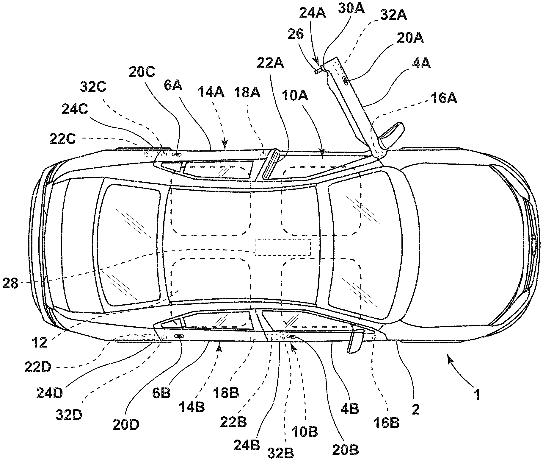
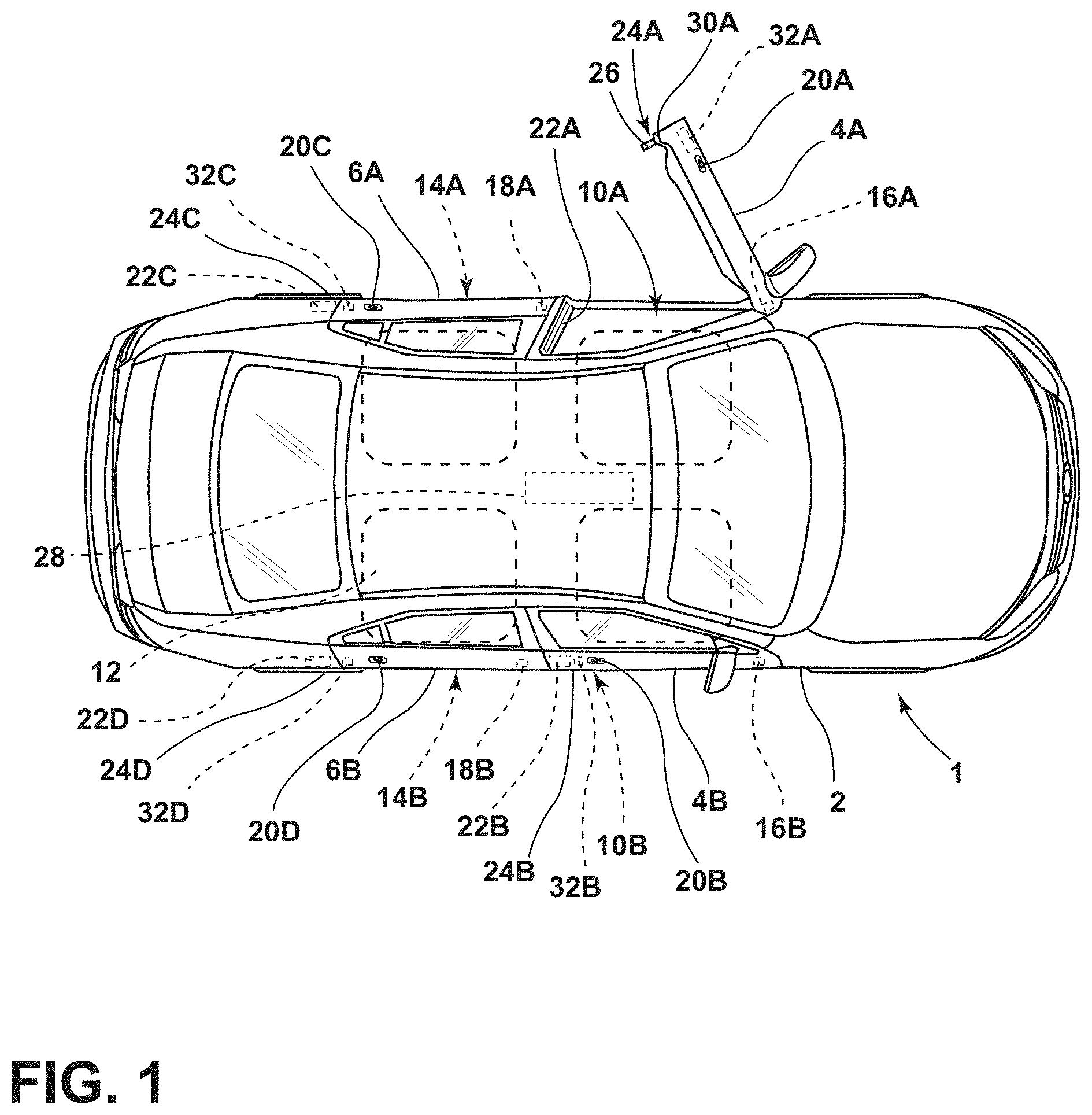
FIG. 1 is a partially schematic plan view of a vehicle including anti-pinch sensors and powered door actuators that open the vehicle doors;
FIG. 2 is a schematic view of a portion of the vehicle of FIG. 1;
FIG. 3 is a schematic view of a portion of the vehicle of FIG. 1;
FIG. 4 is a schematic view of a powered door actuator in a first check position;
FIG. 5 is a schematic view of a powered door actuator in a second check position;
FIG. 6 is a schematic plan view of a vehicle door in a closed position;
FIG. 7 is a schematic plan view of a vehicle door in a partially open position;
FIG. 8 is a schematic plan view of a vehicle door in a fully open position;
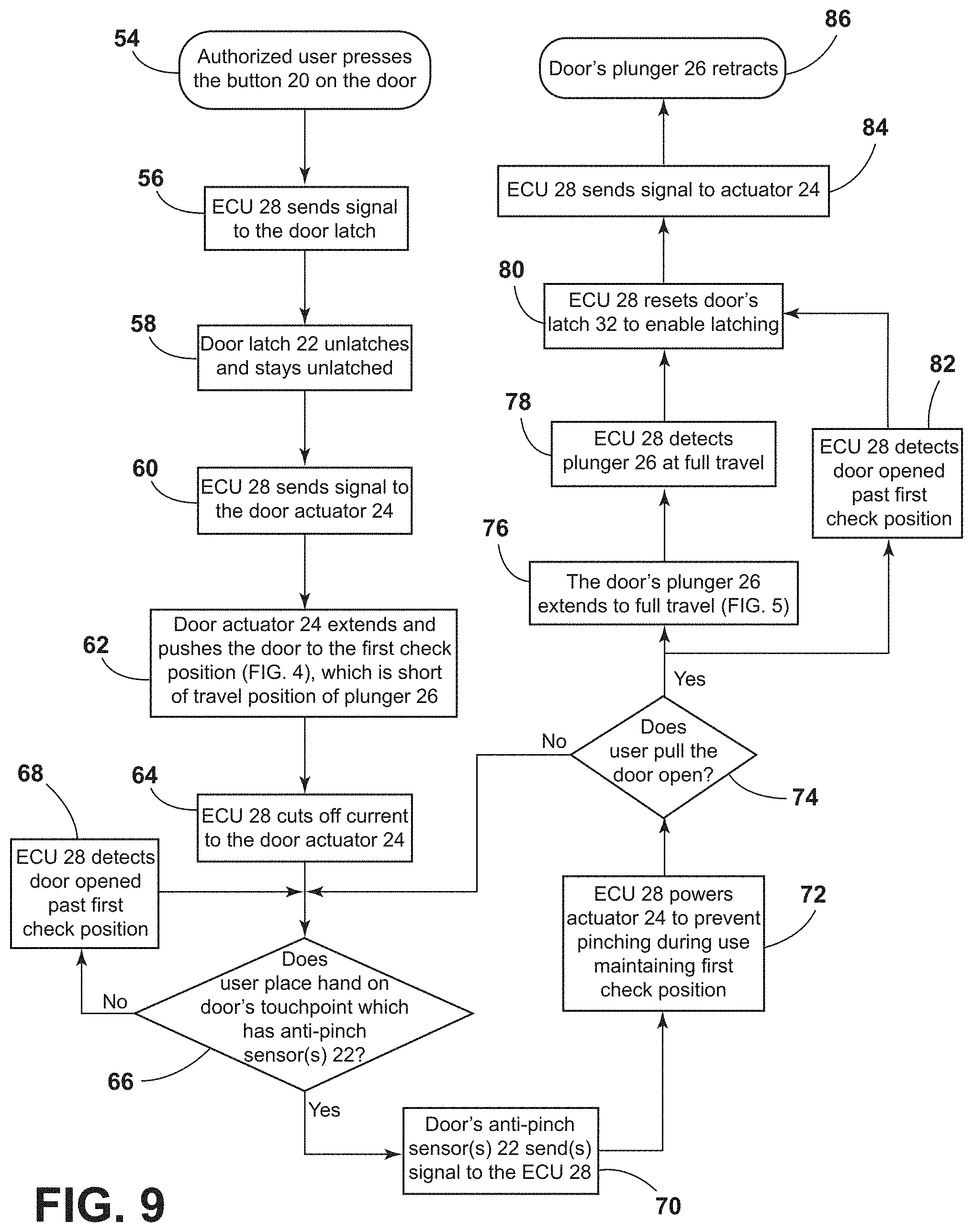
FIG. 9 is a flow chart showing operation of a vehicle including a power release latch and powered door opening actuator with locally controlled anti-pinch door sensors;
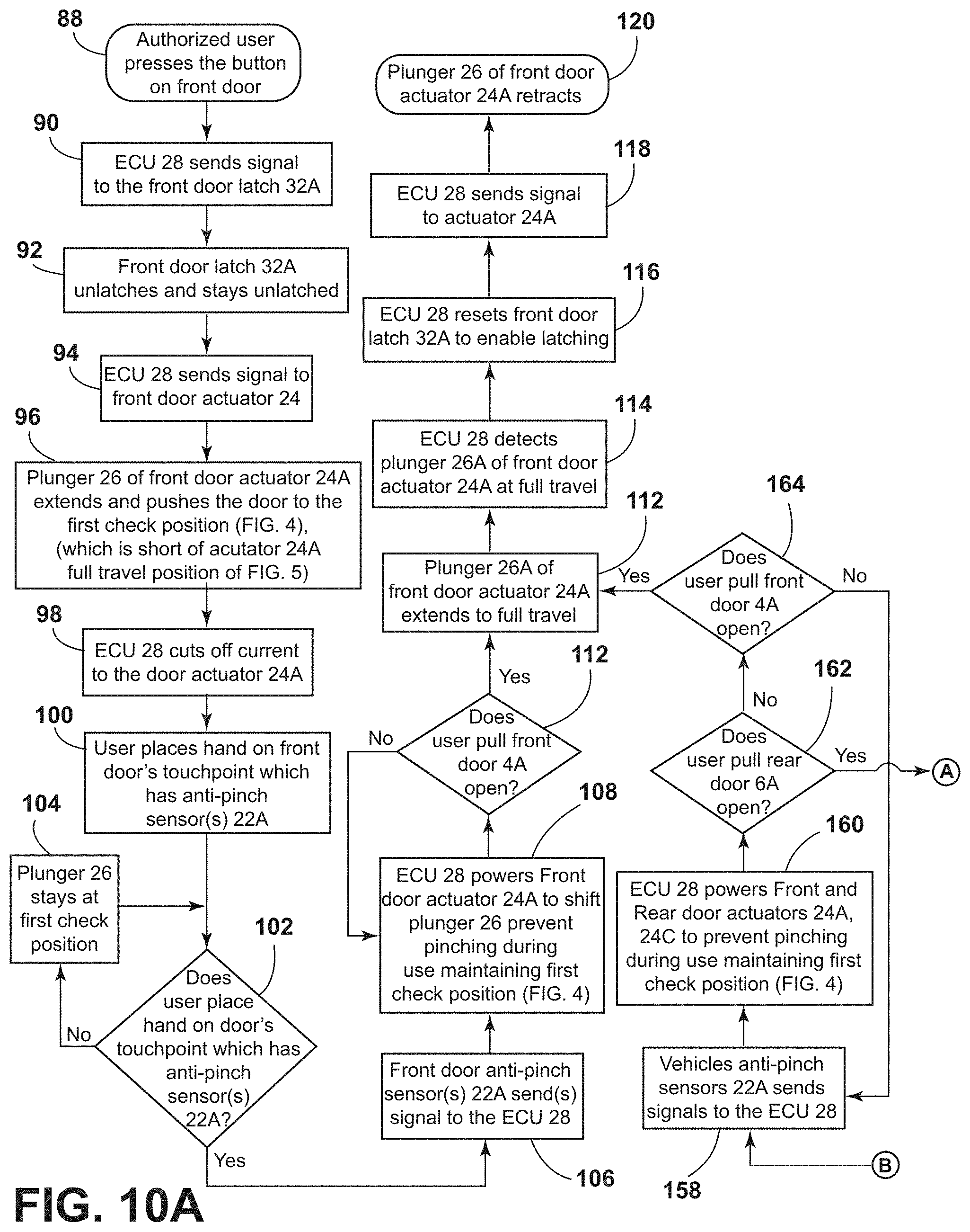
FIG. 10A is a first portion of a flow chart showing operation of a vehicle door system that includes front and rear doors having powered door latches, powered door opening mechanisms and front and rear anti-pinch door sensors;
FIG. 10B is a second portion of the flow chart of FIG. 10A; and rear doors having powered door latches, powered door opening mechanisms and front and rear anti-pinch door sensors;
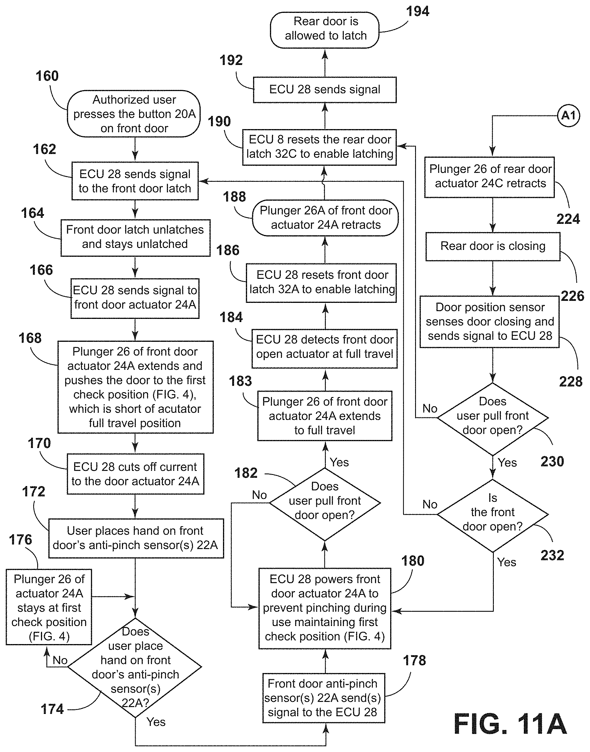
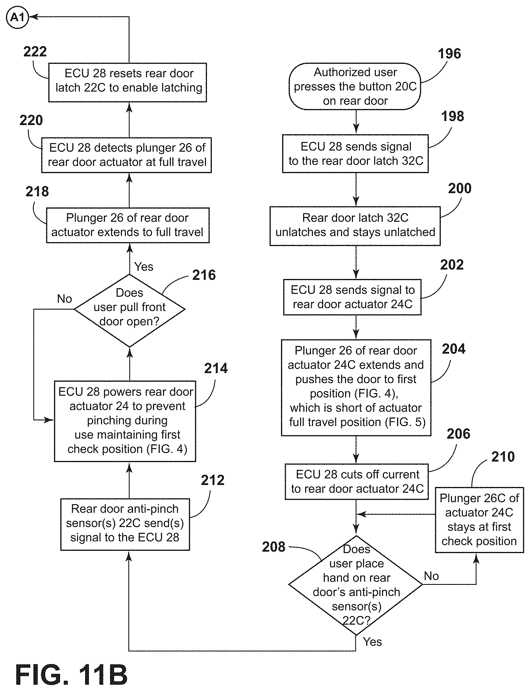
FIG. 11A is a first portion of a flow chart showing vehicle door operation for doors including powered door latches, powered door opening actuators, front and rear anti-pinch sensors, and front and rear door position sensors;
FIG. 11B is a second portion of the flow chart of FIG. 11A;
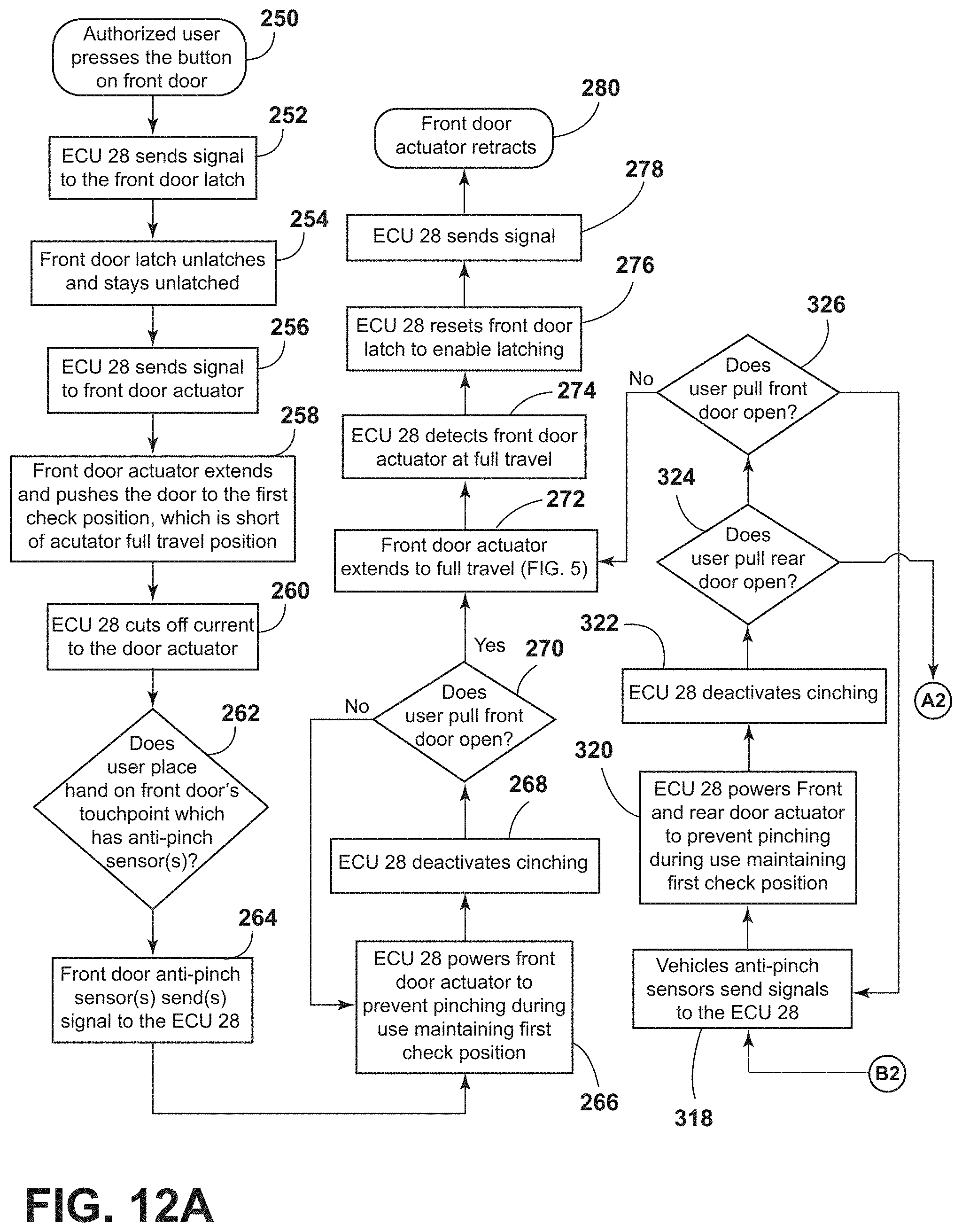
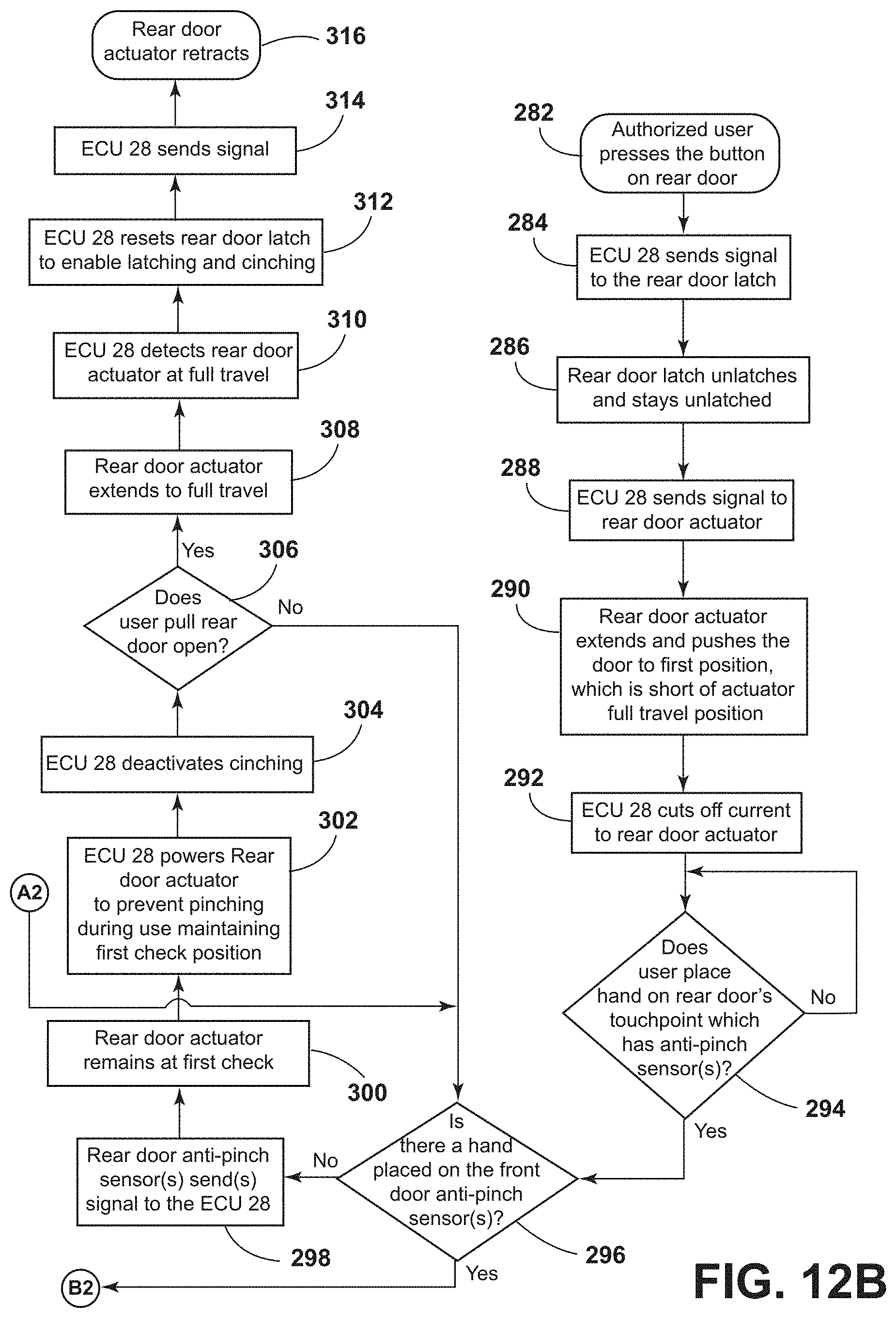
FIG. 12A is a first portion of a flow chart for a door system including powered front and rear door latches, powered front and rear door opening mechanisms, and front and rear anti-pinch door sensors;
FIG. 12B is a second portion of the flow chart of FIG. 12A;
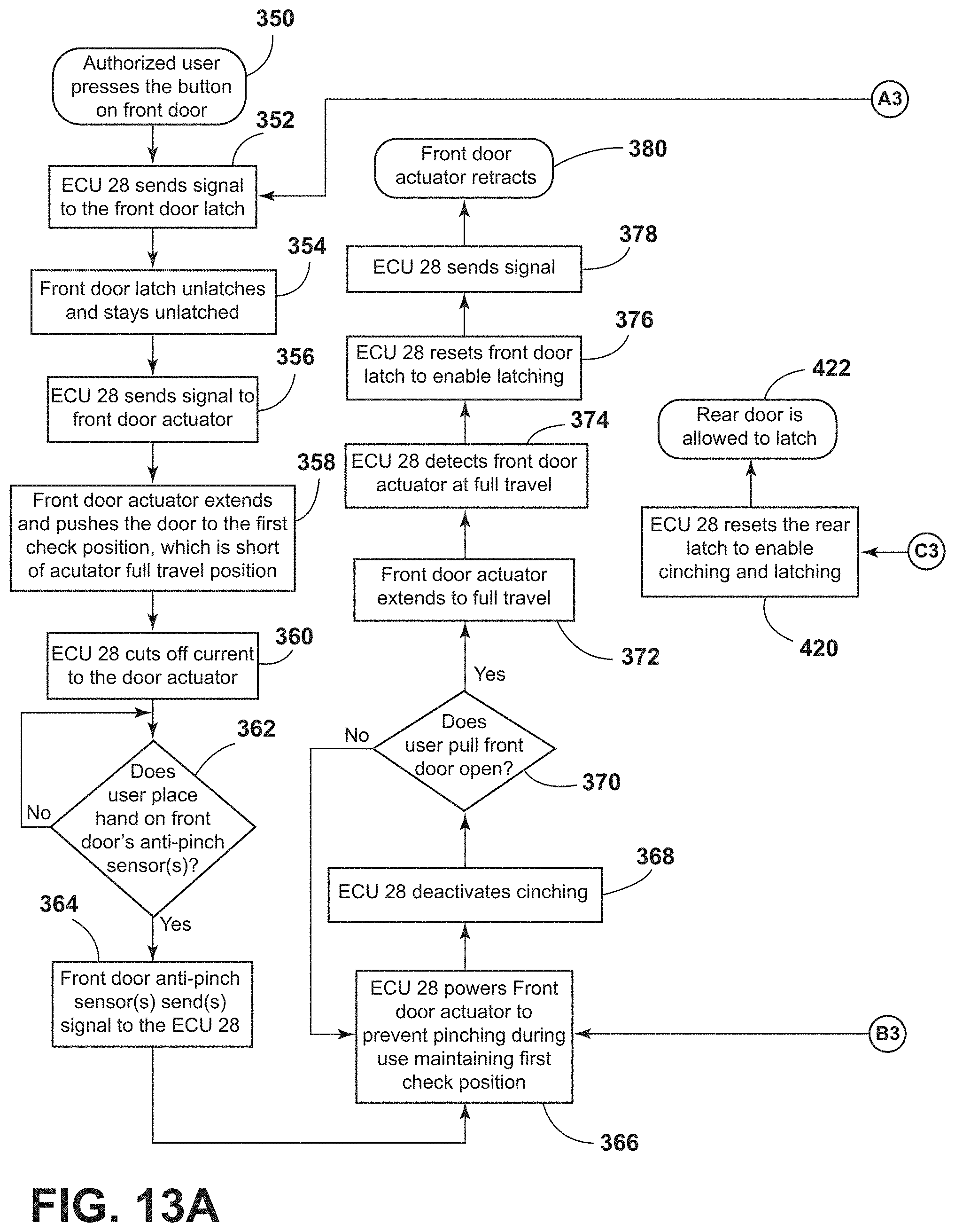
FIG. 13A is a first portion of a flow chart showing operation of a vehicle door system including powered cinching front and rear door latches, powered front and rear door opening actuators, front and rear anti-pinch sensors, and front and rear door position sensors; and
FIG. 13B is a second portion of the flow chart of FIG. 13A.
DETAILED DESCRIPTION OF THE PREFERRED EMBODIMENTS
For purposes of description herein, the terms "upper," "lower," "right," "left," "rear," "front," "vertical," "horizontal," and derivatives thereof shall relate to the invention as oriented in FIG. 1. However, it is to be understood that the invention may assume various alternative orientations and step sequences, except where expressly specified to the contrary. It is also to be understood that the specific devices and processes illustrated in the attached drawings, and described in the following specification are simply exemplary embodiments of the inventive concepts defined in the appended claims. Hence, specific dimensions and other physical characteristics relating to the embodiments disclosed herein are not to be considered as limiting, unless the claims expressly state otherwise.
With reference to FIG. 1, a motor vehicle 1 includes a body structure 2, front doors 4A and 4B, and rear doors 6A and 6B. The front doors 4A and 4B are configured to open and close to provide access to interior 12 of vehicle 1 through front openings 10A and 10B, respectively. Similarly, rear doors 6A and 6B are configured to open and close to provide access through rear door openings 14A and 14B. Front doors 4A and 4B are rotatably mounted to body structure 2 by hinges 16A and 16B, and rear doors 6A and 6B are rotatably mounted to body structure 2 by rear hinges 18A and 18B, respectively. As discussed in more detail below, the vehicle doors 4A, 4B, 6A and 6B may include exterior switches or sensors 20A-20B, respectively that can be actuated by a user to unlatch and open the vehicle doors. Vehicle 1 may comprise a two door vehicle having only front doors 4A and 4B, and front openings 10A and 10B.
Vehicle 1 further includes anti-pinch sensors 22A-22D that are configured to detect a user's hand if the user's hand is inserted into an opening 10A, 10B, 14A, 14B when a vehicle door is opened. Pinch sensors 22A-22D may comprise capacitive sensors, pressure sensitive sensors, or other suitable sensor capable of detecting a user's hand. Pinch sensors 22A-22D may be mounted to the body structure 2 adjacent the door openings. Vehicle door 4A also includes a powered door opener 24 that includes a plunger 26 that can be shifted to a first extended position to partially open the door 4A (see also FIG. 7). The doors 4B, 6A, and 6B may also include powered door opening mechanisms 24. The doors 4A, 4B, 6A, and 6B also include powered latch mechanisms 32A-32D. The powered latches 32A-32D can be actuated by controller 28 to unlatch the doors if unlatch switches 20A-20D, respectively, are actuated by a user. The controller 28 may be operably connected to the anti-pinch sensors 22A-22D, powered door opening mechanisms 24A-24D, and powered latches 32A-32D. Controller 28 may comprise a single central controller as shown in FIG. 1, or controller 28 may comprise separate controllers that are located in each door 4A, 4B, 6A, and 6B. The powered door opening mechanisms 24A-24D and powered latches 32A-32D are described in more detail in U.S. Pat. No. 10,227,810, issued on Mar. 12, 2019, entitled "PRIORITY DRIVEN POWER SIDE DOOR OPEN/CLOSE OPERATIONS," the entire contents of which are incorporated herein by reference. As discussed in the above-referenced '810 patent, powered latches 32A-32D may include a rotating claw that engages a striker on body structure 2 to retain doors 4A, 4B, 6A and 6B in closed positions. A movably pawl engages the claw to prevent rotation of the claw when powered latches 32A-32D are latched. Conversely, the pawl permits rotation of the claw when latches 32A-32D are unlatched. An electrically-powered actuator is operably connected to the pawl and shifts the pawl between engaged (latched), and disengaged (unlatched) positions when electrical power is supplied to the powered actuator by controller 28.
As discussed in more detail below, to enter vehicle 1 a user pushes release switch 20A which is operably connected to a controller or electric control unit ("ECU") 28. It will be understood that controller 28 may comprise various hardware and/or software, and the terms "controller" and "ECU" are not limited to any specific device and/or software. Controller 28 then actuates the powered door opening mechanism 24 to thereby cause the plunger 26 to shift to an extended ("first check") position to thereby at least partially open door 4A whereby rear edge 30A of door 4A is spaced apart from vehicle body 2. A user then grasps edge 30A and pulls door 4A to a fully open position. The other doors 4B, 6A, and 6B may be opened in a substantially similar manner.
The powered door opening mechanism 24 permits elimination of external vehicle door handles that would otherwise be required to permit a user to grasp the door handle to pull the door open.
Opening and closing of the driver's side front and rear doors 4A and 6A is shown schematically in FIGS. 2 and 3. It will be understood that the passenger side doors 4B and 6B operate in a substantially similar manner as driver's side doors 4A and 6A. As discussed below in connection with FIGS. 4-8, in use, a user initially actuates a sensor or switch 20A or 20C to generate an unlatch request to controller 28. For example, if a user pushes the unlatch switch 20A, controller 28 generates a signal to powered latch 32A of front door 4A to thereby provide powered unlatching of latch 32A. Similarly, if unlatch switch 20C is actuated, controller 28 generates a signal to unlatch powered latch 32C of rear door 6A. After the powered latch is unlatched, controller 28 then generates a signal to the powered actuator 24A or 24C, causing plunger 26 to extend and push door 4A or 6A to a partially opened position. A user then grasps rear edge 30A or 30C of door 4A or 6A to pull the door to a fully open position. As a user grasps the edge 30A or 30C, anti-pinch sensors 22A or 22C generate a signal to controller 28 indicating that a user's hand is present. Controller 28 may then generate a signal to retain the plunger 26 in an extended position to prevent pinching of a user's hand.
Referring to FIG. 3, when rear door 6A is opened and front door 4A remains closed, a user may nevertheless insert a hand and grasp rear edge 30A of front door 4A even though front door 4A is in a closed position. If rear door 6A were to be closed this could pinch a user's hand positioned adjacent front pinch sensor 22A. As discussed in more detail below in connection with FIGS. 10A, 10B, 11A, 11B, 12A, 12B, 13A, and 13B, controller 28 is configured/programmed to prevent pinching if the front door 4A is closed while the rear door 6A is open as shown in FIG. 3. As shown in FIG. 3, anti-pinch sensors 122A, 122C, etc. may optionally be mounted to the vehicle doors 4A, 6A adjacent the rear edges 30A, 30C, etc.
With further reference to FIGS. 4 and 5, an electrically-powered door opening mechanism 24A is disposed in an interior space 34A of door 4A between outer side 36A and inner side 38A of door 4A. All doors of the vehicle 1 may include powered door opening mechanisms that are substantially similar to the mechanism 24A. Mechanism 24A may include a housing or base structure 46 and a plunger 26 that is movably interconnected with the housing 46 for reciprocating movement relative to the housing 46. The mechanism 24A may include an electric motor 40 and gear drive 42 that provide for powered movement of plunger 26. A sensor 44 enables controller 28 to determine the position of plunger 26 relative to housing 46. The components of powered actuator 24A are shown schematically in FIGS. 4 and 5. It will be understood that the powered door opening mechanism 24A may have various configurations as required for a particular application. For example, the powered door opening mechanism 24 may be configured as disclosed in U.S. Pat. No. 10,227,810, issued on Mar. 12, 2019, entitled "PRIORITY DRIVEN POWER SIDE DOOR OPEN/CLOSE OPERATIONS."
Plunger 26 may be actuated to extend to a first check position 26A (FIG. 4) in which plunger 26 extends a distance "P1," causing door 4A to open to a first partially open position (see also FIG. 7) whereby a gap "G1" is formed between inner surface 38A of door 4A and surface 50 of vehicle body 2. A pad or surface 48 may be disposed on surface 50 of body 2 in the region where plunger 26 contacts surface 50 of vehicle body 2. As also discussed below, the plunger 26 may be further extended to a fully extended position "P2" that is slightly greater than distance P1 as shown in FIG. 5. Plunger 26 shifts to fully extended position P2 after door 4A has been shifted to a fully open position (e.g. pulled open by a user). Controller 28 may be configured to detect travel of plunger 26 to fully extended position P2, and utilize the P2 position as an indication that the door has been shifted to a fully open position. Alternatively, door hinges 16A, 18A, etc. may include a sensor (not shown) that detects the angular positions of the doors such that controller 28 can determine when the doors are fully open. The second check position P2 and/or rotation sensors are optional, and controller 28 may be configured to operate without a sensor input indicating that a vehicle door has been fully opened. In general, the distance P1 (and gap G1) may be about one to about four inches. The second distance P2 may be, for example, 0.25 inches, 0.50 inches (or more) greater than distance P1.
With further reference to FIGS. 6-8, a user initially actuates switch or sensor 20A when door 4A is in a closed position (FIG. 6). Controller 28 then unlatches the powered latch 32A, and actuates powered door opener 24A to extend plunger 26 to a first check (distance P1) position in which door 4A is in a first partially opened position creating a gap G1 as shown in FIG. 7. A user then grasps edge 30A of door 4A and pulls the door to a fully open position shown in FIG. 8. As discussed below, the plunger 26 is retracted while the door 4A is in a fully open position (FIG. 8), and the powered latch 32A is then reset. A user can then push the door 4A from the open position (FIG. 8) to the closed position (FIG. 6), and powered latch 32A retains the door 4A in the fully closed position (FIG. 6). Powered latch 32A may comprise a cinching door latch. For example, the claw 180 of the powered latch described in the U.S. Pat. No. 10,227,810 may be operably connected to a powered actuator (e.g. electric motor) whereby the claw rotates from an open/released position to a latched/closed position to engage a striker to pull the door to a fully-closed position. If the powered latch 32A is a cinching door latch, door 4A may be initially pushed to a mostly closed position 52 (FIG. 8), and the powered latch 32A may then be actuated to shift the door to the fully closed position of FIG. 6. Cinching latch mechanisms are disclosed in U.S. Pat. No. 9,004,570, issued on Apr. 14, 2015 and entitled "ADJUSTABLE LATCH ASSEMBLY" and U.S. Pat. No. 9,951,547, issued on Apr. 24, 2018 and entitled "ADJUSTABLE DECKLID LATCH ASSEMBLY" the entire contents of each being incorporated herein by reference. Cinching door latches are generally known in the art, and a detailed description of a cinching door latch is therefore not believed to be necessary. It will be understood that all of the doors 4A, 4B, 6A, and 6B of vehicle 1 may operate in substantially the same manner as the doors shown and described above in connection with FIGS. 2-8.
Operation of a single vehicle door having a locally controlled anti-pinch door sensor is shown in the flow chart of FIG. 9. The control arrangement of FIG. 9 may be utilized if, for example, vehicle 1 includes only front doors 4A and 4B, such that a pinch situation involving adjacent front and rear doors (e.g. FIG. 3) is not present. In steps 54-62, a user presses or otherwise actuates a sensor or button 20 on the outside of the vehicle door, and the controller/ECU 28 sends a signal to the powered door opening mechanism or actuator 24, and plunger 26 then extends to a first check position 26A (FIG. 4). At step 64, the ECU 28 cuts off electrical current to the door actuator 24. At step 66, the ECU 28 determines if a user's hand is detected by anti-pinch sensors 22. If not, the process continues at step 68, and ECU 28 determines if the door has been opened past the first check position of FIG. 4. At step 66, if a user's hand is detected, the process continues to step 70, and the anti-pinch sensors 22 send a signal to the ECU 28. At step 72, the ECU 28 provides electrical power to the actuator 24 to retain the plunger 26 in a first check position (FIG. 4) and prevent pinching. At step 74, if a user does not pull the door open, the process goes back to step 66 described above. If the user does pull the door open at step 74, the process may optionally continue at step 76 and extend plunger 26 to the full travel position of FIG. 5. The ECU 28 detects that the plunger 26 is in the full travel position (FIG. 5) at step 78, and the ECU 28 determines (i.e. assumes) that the door has been fully opened because the plunger 26 is in the fully extended position, and the process then continues at step 80 and the ECU 28 resets the doors powered latch 32 to enable latching. Alternatively, if the door includes sensors that directly detect that the door has been opened past the first check position as shown at step 82, the process generally proceeds from step 74 to step 82, and then to step 80. After step 80, the ECU 28 sends a signal to the powered door actuator 24 to retract the plunger 26 as shown at step 86. A user can then push on the door to return it to its closed position. Because the plunger 26 is retracted at step 86, the plunger 26 does not in any way interfere with closing of the vehicle door.
The flow chart of FIGS. 10A and 10B shows operation of a vehicle 1 including adjacent front and rear doors (e.g. FIGS. 2 and 3). Front door operation begins at step 88 (FIG. 10A), and rear door operation begins at step 122 (FIG. 10B). Steps 88-110 of FIG. 10A are substantially similar to steps 54-72 described above in FIG. 9, and steps 122-136 of FIG. 10B are substantially similar to steps 54-66 of FIG. 9. However, if the rear door is opened, and if a hand is detected by the front door anti pinch sensors 22A (step 138; FIG. 10B), the process moves from step 138 to step 158 (FIG. 10A), and the anti-pinch sensor 22A of the front door sends a signal to the ECU 28. At step 160, the ECU 28 then powers both the front and rear door actuators 24A and 24C to maintain the doors in the first check position (FIG. 4) to prevent pinching. At step 162, a user pulls the rear door 6A open, the process continues to step 138 (FIG. 10B). If a user does not pull the rear door open at step 162, the process continues as shown at step 164. At step 112 (optional) the ECU 28 determines that the front door 4A is open because plunger 26A is at full travel (FIG. 5). Similarly, at step 148 (FIG. 10B), if the rear door actuator is at full travel the ECU 28 determines at step 150 that the rear doors opened. It will be understood that the vehicle doors may include sensors that enable ECU 28 to determine if the door is fully opened, such that the ECU 28 does not necessarily need to use full travel of plungers 26 to determine if the door is fully open. After the ECU 28 detects that the front or rear door is fully open, the ECU 28 resets the powered latches and retracts the plungers of the powered door actuators 24A and 24C to permit a user to return the door to a closed position.
The flow chart of FIGS. 11A and 11B shows operation of a vehicle 1 including front and rear doors and door position sensors. Operation of the front door generally begins at step 160 (FIG. 11A), and operation of the rear door generally begins at step 196 (FIG. 11B). The door operations of FIGS. 11A and 11B are similar to the operations of FIGS. 10A and 10B, respectively. However, rear door operation further includes determining if the front door is open at step 232 (FIG. 11A). If the front door is not open, the process continues to step 162 as shown in FIG. 11A. Thus, as shown in FIG. 11A if the rear door is closed and the front door is open (Step 232), the ECU 28 unlatches the front door is shown at steps 162 and 164.
The flow chart of FIGS. 12A and 12B shows operation of a vehicle including front and rear doors with powered latches 32A and 32C that comprise cinching latches. The operation shown in FIGS. 12A and 12B is generally similar to the vehicle door operations described above. However, in FIGS. 12A and 12B the ECU 28 actuates the cinching sensors as required.
The flow chart of FIGS. 13A and 13B shows operation of a vehicle including front and rear doors having powered cinching latches, door position sensors, and anti-pinch sensors. The operations shown in FIGS. 13A and 13B are generally similar to the operations discussed above in connection with FIGS. 9, 10A, 10B, 11A and 11B, and 12A and 12B. However, as shown in FIGS. 13A and 13B, if the vehicle includes both cinching latches and door position sensors, the ECU 28 utilizes the door position data to control the cinching latches and/or the powered door opening mechanism.
It is to be understood that variations and modifications can be made on the aforementioned structure without departing from the concepts of the present invention, and further it is to be understood that such concepts are intended to be covered by the following claims unless these claims by their language expressly state otherwise.
* * * * *
References
-
youtube.com/watch?v=DLDqmGQU6L0
-
autoblog.com/2011/05/14/friends-videotape-man-trapped-inside-c6-corvette-with-dead-bat
-
corvetteonline.com/news/zr1-owner-calls-911-after-locking-self-in-car
-
-
nhtsa.gov/cars/rules/rulings/DoorLocks/DoorLocks_NPRM.html#VI_C
-
oldcarsweekly.com/car-of-the-week-car-of-the-week-1947-lincoln-convertible
D00000
D00001
D00002
D00003
D00004
D00005
D00006
D00007
D00008
D00009
D00010
D00011
D00012

XML
uspto.report is an independent third-party trademark research tool that is not affiliated, endorsed, or sponsored by the United States Patent and Trademark Office (USPTO) or any other governmental organization. The information provided by uspto.report is based on publicly available data at the time of writing and is intended for informational purposes only.
While we strive to provide accurate and up-to-date information, we do not guarantee the accuracy, completeness, reliability, or suitability of the information displayed on this site. The use of this site is at your own risk. Any reliance you place on such information is therefore strictly at your own risk.
All official trademark data, including owner information, should be verified by visiting the official USPTO website at www.uspto.gov. This site is not intended to replace professional legal advice and should not be used as a substitute for consulting with a legal professional who is knowledgeable about trademark law.