Method and device for inserting a tongue
Blomgren , et al. March 2, 2
U.S. patent number 10,933,592 [Application Number 15/635,619] was granted by the patent office on 2021-03-02 for method and device for inserting a tongue. This patent grant is currently assigned to VALINGE INNOVATION AB. The grantee listed for this patent is VALINGE INNOVATION AB. Invention is credited to Andreas Blomgren, Jonas Fransson.


| United States Patent | 10,933,592 |
| Blomgren , et al. | March 2, 2021 |
Method and device for inserting a tongue
Abstract
A method and device for inserting a tongue in an insertion groove in a panel by a device, wherein the method includes: displacing a tongue guiding device in a first direction by displacing a puncher in the first direction, and displacing a tongue between a first part and a second part of the tongue guiding device and into an insertion groove in panel by further displacing the puncher.
| Inventors: | Blomgren; Andreas (Ljugskile, SE), Fransson; Jonas (Allerum, SE) | ||||||||||
|---|---|---|---|---|---|---|---|---|---|---|---|
| Applicant: |
|
||||||||||
| Assignee: | VALINGE INNOVATION AB (Viken,
SE) |
||||||||||
| Family ID: | 1000005392415 | ||||||||||
| Appl. No.: | 15/635,619 | ||||||||||
| Filed: | June 28, 2017 |
Prior Publication Data
| Document Identifier | Publication Date | |
|---|---|---|
| US 20180001573 A1 | Jan 4, 2018 | |
Foreign Application Priority Data
| Jun 29, 2016 [SE] | 1650938-2 | |||
| Current U.S. Class: | 1/1 |
| Current CPC Class: | B29C 66/7487 (20130101); F16B 12/20 (20130101); B29C 65/565 (20130101); B29C 66/824 (20130101); B29C 66/124 (20130101); B29L 2031/44 (20130101); A47B 2230/0096 (20130101); A47B 2230/0081 (20130101) |
| Current International Class: | B29C 65/00 (20060101); F16B 12/20 (20060101); B29C 65/56 (20060101) |
| Field of Search: | ;221/251 |
References Cited [Referenced By]
U.S. Patent Documents
| 1194636 | August 1916 | Joy |
| 1902716 | March 1933 | Newton |
| 3114477 | December 1963 | Dixon |
| 3147522 | September 1964 | Schumm |
| 3381730 | May 1968 | Omholt |
| 3572224 | March 1971 | Perry |
| 3579941 | May 1971 | Tibbals |
| 3584761 | June 1971 | Flanigan |
| 3720027 | March 1973 | Christensen |
| 3760485 | September 1973 | Smith |
| 3760547 | September 1973 | Brenneman |
| 3778954 | December 1973 | Meserole |
| 3919820 | November 1975 | Green |
| 3930808 | January 1976 | Miller |
| 3961408 | June 1976 | Goodsmith |
| 4048105 | September 1977 | Salisbury |
| 4648165 | March 1987 | Whitehorne |
| 4899438 | February 1990 | Muller |
| 5105980 | April 1992 | Hofmann |
| 5174022 | December 1992 | Phillips et al. |
| 5582611 | December 1996 | Tsuruta |
| 5636426 | June 1997 | Luckhardt |
| 5810239 | September 1998 | Stich |
| 5996876 | December 1999 | Dickhoff et al. |
| 6098442 | August 2000 | Walldorf |
| 6273315 | August 2001 | McGuinness |
| 6314701 | November 2001 | Meyerson |
| 6363677 | April 2002 | Chen et al. |
| 6385936 | May 2002 | Schneider |
| 6418683 | July 2002 | Martensson et al. |
| 6446413 | September 2002 | Gruber |
| 6490836 | December 2002 | Moriau et al. |
| 6505452 | January 2003 | Hannig |
| 6592015 | July 2003 | Gostylla |
| 6631827 | October 2003 | Goodsmith |
| 6647690 | November 2003 | Martensson |
| 6651400 | November 2003 | Murphy |
| 6655573 | December 2003 | Chang |
| 6763643 | July 2004 | Martensson |
| 6766622 | July 2004 | Thiers |
| 6769835 | August 2004 | Stridsman |
| 6804926 | October 2004 | Eisermann |
| 6807719 | October 2004 | Herr et al. |
| 6854235 | February 2005 | Martensson |
| 6880307 | April 2005 | Schwitte et al. |
| 7040068 | May 2006 | Moriau et al. |
| 7051486 | May 2006 | Pervan |
| 7188456 | March 2007 | Knauseder |
| 7451578 | November 2008 | Hannig |
| 7454875 | November 2008 | Pervan et al. |
| 7568322 | August 2009 | Pervan |
| 7584583 | September 2009 | Bergelin et al. |
| 7614197 | November 2009 | Nelson |
| 7617651 | November 2009 | Grafenauer |
| 7621092 | November 2009 | Groeke et al. |
| 7634884 | December 2009 | Pervan |
| 7637068 | December 2009 | Pervan |
| 7677005 | March 2010 | Pervan |
| 7721503 | May 2010 | Pervan et al. |
| 7757452 | July 2010 | Pervan |
| 7802411 | September 2010 | Pervan |
| 7811150 | November 2010 | Pervan |
| 7841144 | November 2010 | Pervan et al. |
| 7841145 | November 2010 | Pervan et al. |
| 7856789 | December 2010 | Eisermann |
| 7861482 | January 2011 | Pervan et al. |
| 7866110 | January 2011 | Pervan |
| 7908815 | March 2011 | Pervan et al. |
| 7908816 | March 2011 | Grafenauer |
| 7930862 | April 2011 | Bergelin et al. |
| 7980041 | July 2011 | Pervan |
| 8033074 | October 2011 | Pervan |
| 8042311 | October 2011 | Pervan |
| 8061104 | November 2011 | Pervan |
| 8079196 | December 2011 | Pervan |
| 8091238 | January 2012 | Hannig |
| 8112967 | February 2012 | Pervan et al. |
| 8171692 | May 2012 | Pervan |
| 8181416 | May 2012 | Pervan et al. |
| 8234830 | August 2012 | Pervan et al. |
| 8256104 | September 2012 | Fulbright |
| 8341914 | January 2013 | Pervan et al. |
| 8341915 | January 2013 | Pervan |
| 8353140 | January 2013 | Pervan et al. |
| 8359805 | January 2013 | Pervan et al. |
| 8381476 | February 2013 | Hannig |
| 8381477 | February 2013 | Pervan et al. |
| 8387327 | March 2013 | Pervan |
| 8448402 | May 2013 | Pervan et al. |
| 8499521 | August 2013 | Pervan et al. |
| 8505257 | August 2013 | Boo et al. |
| 8528289 | September 2013 | Pervan et al. |
| 8544230 | October 2013 | Pervan |
| 8544234 | October 2013 | Pervan et al. |
| 8572922 | November 2013 | Pervan |
| 8596013 | December 2013 | Boo |
| 8627862 | January 2014 | Pervan |
| 8640424 | February 2014 | Pervan et al. |
| 8650738 | February 2014 | Schulte |
| 8650826 | February 2014 | Pervan et al. |
| 8677714 | March 2014 | Pervan |
| 8689512 | April 2014 | Pervan |
| 8707650 | April 2014 | Pervan |
| 8713886 | May 2014 | Boo et al. |
| 8733065 | May 2014 | Pervan |
| 8733410 | May 2014 | Pervan |
| 8763340 | July 2014 | Pervan |
| 8763341 | July 2014 | Pervan |
| 8769905 | July 2014 | Pervan |
| 8776473 | July 2014 | Pervan et al. |
| 8844236 | September 2014 | Pervan et al. |
| 8857126 | October 2014 | Pervan et al. |
| 8869485 | October 2014 | Pervan |
| 8898988 | December 2014 | Pervan |
| 8925274 | January 2015 | Pervan et al. |
| 8959866 | February 2015 | Pervan |
| 8973331 | March 2015 | Boo |
| 9027306 | May 2015 | Pervan |
| 9051738 | June 2015 | Pervan et al. |
| 9068360 | June 2015 | Pervan |
| 9091077 | July 2015 | Boo |
| 9120141 | September 2015 | Clew |
| 9194134 | November 2015 | Nygren et al. |
| 9212492 | December 2015 | Pervan et al. |
| 9216541 | December 2015 | Boo et al. |
| 9238917 | January 2016 | Pervan et al. |
| 9284737 | March 2016 | Pervan et al. |
| 9309679 | April 2016 | Pervan et al. |
| 9316002 | April 2016 | Boo |
| 9340974 | May 2016 | Pervan |
| 9347469 | May 2016 | Pervan |
| 9359774 | June 2016 | Pervan |
| 9366036 | June 2016 | Pervan |
| 9376821 | June 2016 | Pervan et al. |
| 9382716 | July 2016 | Pervan et al. |
| 9388584 | July 2016 | Pervan et al. |
| 9428919 | August 2016 | Pervan et al. |
| 9453347 | September 2016 | Pervan et al. |
| 9458634 | October 2016 | Derelov |
| 9482012 | November 2016 | Nygren et al. |
| 9540826 | January 2017 | Pervan et al. |
| 9555529 | January 2017 | Ronconi |
| 9663940 | May 2017 | Boo |
| 9725912 | August 2017 | Pervan |
| 9771723 | September 2017 | Pervan |
| 9777487 | October 2017 | Pervan et al. |
| 9803374 | October 2017 | Pervan |
| 9803375 | October 2017 | Pervan |
| 9856656 | January 2018 | Pervan |
| 9874027 | January 2018 | Pervan |
| 9945130 | April 2018 | Nygren et al. |
| 9951526 | April 2018 | Boo et al. |
| 10006210 | June 2018 | Pervan et al. |
| 10017948 | July 2018 | Boo |
| 10113319 | October 2018 | Pervan |
| 10125488 | November 2018 | Boo |
| 10138636 | November 2018 | Pervan |
| 10161139 | December 2018 | Pervan |
| 10180005 | January 2019 | Pervan et al. |
| 10214915 | February 2019 | Pervan et al. |
| 10214917 | February 2019 | Pervan et al. |
| 10240348 | March 2019 | Pervan et al. |
| 10240349 | March 2019 | Pervan et al. |
| 10246883 | April 2019 | Derelov |
| 10307815 | June 2019 | Badent |
| 10352049 | July 2019 | Boo |
| 10358830 | July 2019 | Pervan |
| 10378217 | August 2019 | Pervan |
| 10458125 | October 2019 | Pervan |
| 10526792 | January 2020 | Pervan et al. |
| 10538922 | January 2020 | Pervan |
| 10570625 | February 2020 | Pervan |
| 10640989 | May 2020 | Pervan |
| 10655339 | May 2020 | Pervan |
| 10669723 | June 2020 | Pervan et al. |
| 10794065 | October 2020 | Boo et al. |
| 10828798 | November 2020 | Fransson |
| 2002/0031646 | March 2002 | Chen et al. |
| 2002/0170259 | November 2002 | Ferris |
| 2002/0178674 | December 2002 | Pervan |
| 2003/0009971 | January 2003 | Palmberg |
| 2003/0024199 | February 2003 | Pervan et al. |
| 2003/0037504 | February 2003 | Schwitte et al. |
| 2003/0180091 | September 2003 | Stridsman |
| 2003/0188504 | October 2003 | Ralf |
| 2003/0196405 | October 2003 | Pervan |
| 2004/0016196 | January 2004 | Pervan |
| 2004/0031227 | February 2004 | Knauseder |
| 2004/0060255 | April 2004 | Knauseder |
| 2004/0068954 | April 2004 | Martensson |
| 2004/0123548 | July 2004 | Gimpel et al. |
| 2004/0128934 | July 2004 | Hecht |
| 2004/0200175 | October 2004 | Weber |
| 2004/0211143 | October 2004 | Hanning |
| 2004/0244325 | December 2004 | Nelson |
| 2004/0261348 | December 2004 | Vulin |
| 2005/0081373 | April 2005 | Seidler |
| 2005/0160694 | July 2005 | Pervan |
| 2005/0205161 | September 2005 | Lewark |
| 2005/0210810 | September 2005 | Pervan |
| 2006/0070333 | April 2006 | Pervan |
| 2006/0101769 | May 2006 | Pervan |
| 2006/0162814 | July 2006 | Symossek et al. |
| 2006/0236642 | October 2006 | Pervan |
| 2006/0260254 | November 2006 | Pervan et al. |
| 2007/0006543 | January 2007 | Engstrom |
| 2007/0011981 | January 2007 | Eiserman |
| 2007/0028547 | February 2007 | Grafenauer |
| 2007/0151189 | July 2007 | Yang et al. |
| 2007/0175156 | August 2007 | Pervan et al. |
| 2007/0193178 | August 2007 | Groeke et al. |
| 2008/0000180 | January 2008 | Pervan et al. |
| 2008/0000187 | January 2008 | Pervan et al. |
| 2008/0010931 | January 2008 | Pervan et al. |
| 2008/0010937 | January 2008 | Pervan et al. |
| 2008/0028707 | February 2008 | Pervan |
| 2008/0034708 | February 2008 | Pervan |
| 2008/0041008 | February 2008 | Pervan |
| 2008/0066415 | March 2008 | Pervan |
| 2008/0104921 | May 2008 | Pervan et al. |
| 2008/0110125 | May 2008 | Pervan |
| 2008/0134607 | June 2008 | Pervan |
| 2008/0134613 | June 2008 | Pervan |
| 2008/0134614 | June 2008 | Pervan |
| 2008/0155930 | July 2008 | Pervan et al. |
| 2008/0216434 | September 2008 | Pervan |
| 2008/0216920 | September 2008 | Pervan |
| 2008/0295432 | December 2008 | Pervan et al. |
| 2009/0133353 | May 2009 | Pervan et al. |
| 2009/0193748 | August 2009 | Boo et al. |
| 2010/0043333 | February 2010 | Hannig et al. |
| 2010/0218360 | September 2010 | Mangone, Jr. |
| 2010/0293879 | November 2010 | Pervan et al. |
| 2010/0300031 | December 2010 | Pervan et al. |
| 2010/0313714 | December 2010 | Smith |
| 2010/0319290 | December 2010 | Pervan |
| 2010/0319291 | December 2010 | Pervan et al. |
| 2011/0030303 | February 2011 | Pervan et al. |
| 2011/0041996 | February 2011 | Pervan |
| 2011/0088344 | April 2011 | Pervan et al. |
| 2011/0088345 | April 2011 | Pervan |
| 2011/0088346 | April 2011 | Hannig |
| 2011/0094083 | April 2011 | Schulte |
| 2011/0154763 | June 2011 | Bergelin et al. |
| 2011/0167750 | July 2011 | Pervan |
| 2011/0167751 | July 2011 | Engstrom |
| 2011/0225922 | September 2011 | Pervan et al. |
| 2011/0252733 | October 2011 | Pervan |
| 2011/0283650 | November 2011 | Pervan et al. |
| 2012/0017533 | January 2012 | Pervan et al. |
| 2012/0031029 | February 2012 | Pervan et al. |
| 2012/0036804 | February 2012 | Pervan |
| 2012/0073235 | March 2012 | Hannig |
| 2012/0151865 | June 2012 | Pervan et al. |
| 2012/0174515 | July 2012 | Pervan |
| 2012/0174520 | July 2012 | Pervan |
| 2012/0279161 | November 2012 | H{dot over (a)}kansson et al. |
| 2013/0008117 | January 2013 | Pervan |
| 2013/0014463 | January 2013 | Pervan |
| 2013/0019555 | January 2013 | Pervan |
| 2013/0042562 | February 2013 | Pervan |
| 2013/0042563 | February 2013 | Pervan |
| 2013/0042564 | February 2013 | Pervan et al. |
| 2013/0042565 | February 2013 | Pervan |
| 2013/0047536 | February 2013 | Pervan |
| 2013/0081349 | April 2013 | Pervan et al. |
| 2013/0111845 | May 2013 | Pervan |
| 2013/0145708 | June 2013 | Pervan |
| 2013/0160391 | June 2013 | Pervan et al. |
| 2013/0232905 | September 2013 | Pervan |
| 2013/0239508 | September 2013 | Pervan et al. |
| 2013/0263454 | October 2013 | Boo et al. |
| 2013/0263547 | October 2013 | Boo |
| 2013/0318906 | December 2013 | Pervan et al. |
| 2014/0007539 | January 2014 | Pervan et al. |
| 2014/0020324 | January 2014 | Pervan |
| 2014/0033634 | February 2014 | Pervan |
| 2014/0042203 | February 2014 | Abe |
| 2014/0053497 | February 2014 | Pervan et al. |
| 2014/0059966 | March 2014 | Boo |
| 2014/0069043 | March 2014 | Pervan |
| 2014/0090335 | April 2014 | Pervan et al. |
| 2014/0109501 | April 2014 | Pervan |
| 2014/0109506 | April 2014 | Pervan et al. |
| 2014/0123586 | May 2014 | Pervan et al. |
| 2014/0138422 | May 2014 | Ronconi |
| 2014/0150369 | June 2014 | Hannig |
| 2014/0190112 | July 2014 | Pervan |
| 2014/0208677 | July 2014 | Pervan et al. |
| 2014/0207931 | August 2014 | Pervan |
| 2014/0223852 | August 2014 | Pervan |
| 2014/0237931 | August 2014 | Pervan |
| 2014/0250813 | September 2014 | Nygren et al. |
| 2014/0260060 | September 2014 | Pervan et al. |
| 2014/0305065 | October 2014 | Pervan |
| 2014/0338177 | November 2014 | Vermeulen et al. |
| 2014/0366476 | December 2014 | Pervan |
| 2014/0373478 | December 2014 | Pervan et al. |
| 2014/0373480 | December 2014 | Pervan et al. |
| 2015/0000221 | January 2015 | Boo |
| 2015/0013260 | January 2015 | Pervan |
| 2015/0059281 | March 2015 | Pervan |
| 2015/0089896 | April 2015 | Pervan et al. |
| 2015/0121796 | May 2015 | Pervan |
| 2015/0152644 | June 2015 | Boo |
| 2015/0167318 | June 2015 | Pervan |
| 2015/0211239 | July 2015 | Pervan |
| 2015/0233125 | August 2015 | Pervan et al. |
| 2015/0267419 | September 2015 | Pervan |
| 2015/0300029 | October 2015 | Pervan |
| 2015/0330088 | November 2015 | Derelov |
| 2015/0336224 | November 2015 | Liu |
| 2015/0337537 | November 2015 | Boo |
| 2016/0032596 | February 2016 | Nygren et al. |
| 2016/0060879 | March 2016 | Pervan |
| 2016/0069088 | March 2016 | Boo et al. |
| 2016/0076260 | March 2016 | Pervan et al. |
| 2016/0090744 | March 2016 | Pervan et al. |
| 2016/0129573 | May 2016 | Anstett et al. |
| 2016/0153200 | June 2016 | Pervan |
| 2016/0168866 | June 2016 | Pervan et al. |
| 2016/0186426 | June 2016 | Boo |
| 2016/0194884 | July 2016 | Pervan et al. |
| 2016/0201336 | July 2016 | Pervan |
| 2016/0251859 | September 2016 | Pervan et al. |
| 2016/0251860 | September 2016 | Pervan |
| 2016/0281368 | September 2016 | Pervan et al. |
| 2016/0281370 | September 2016 | Pervan et al. |
| 2016/0326751 | November 2016 | Pervan |
| 2016/0340913 | November 2016 | Derelov |
| 2017/0037641 | February 2017 | Nygren et al. |
| 2017/0081860 | March 2017 | Boo |
| 2017/0254096 | September 2017 | Pervan |
| 2017/0321433 | November 2017 | Pervan et al. |
| 2017/0362834 | December 2017 | Pervan et al. |
| 2018/0001509 | January 2018 | Myllykangas et al. |
| 2018/0001510 | January 2018 | Fransson |
| 2018/0002933 | January 2018 | Pervan |
| 2018/0030737 | February 2018 | Pervan |
| 2018/0030738 | February 2018 | Pervan |
| 2018/0119431 | May 2018 | Pervan et al. |
| 2018/0178406 | June 2018 | Fransson et al. |
| 2019/0024387 | January 2019 | Pervan et al. |
| 2019/0048592 | February 2019 | Boo |
| 2019/0048596 | February 2019 | Pervan |
| 2019/0063076 | February 2019 | Boo et al. |
| 2019/0093370 | March 2019 | Pervan et al. |
| 2019/0093371 | March 2019 | Pervan |
| 2019/0119928 | April 2019 | Pervan et al. |
| 2019/0127989 | May 2019 | Kell |
| 2019/0127990 | May 2019 | Pervan et al. |
| 2019/0169859 | June 2019 | Pervan et al. |
| 2019/0232473 | August 2019 | Fransson et al. |
| 2019/0271165 | September 2019 | Boo |
| 2019/0376298 | December 2019 | Pervan et al. |
| 2019/0394314 | December 2019 | Pervan et al. |
| 2020/0087927 | March 2020 | Pervan |
| 2020/0102756 | April 2020 | Pervan |
| 2020/0109569 | April 2020 | Pervan |
| 2020/0149289 | May 2020 | Pervan |
| 2020/0263437 | August 2020 | Pervan |
| 2020/0284045 | September 2020 | Kell |
| 2020/0318667 | October 2020 | Derelov |
| 25 05 489 | Aug 1976 | DE | |||
| 197 52 286 | May 1999 | DE | |||
| 202 05 774 | Aug 2002 | DE | |||
| 203 20 799 | Apr 2005 | DE | |||
| 10 2004 055 951 | Jul 2005 | DE | |||
| 10 2006 057 491 | Jun 2008 | DE | |||
| 0 974 713 | Jan 2000 | EP | |||
| 1 420 125 | May 2004 | EP | |||
| 1 650 375 | Apr 2006 | EP | |||
| 1 674 223 | Jun 2006 | EP | |||
| 1 650 375 | Sep 2006 | EP | |||
| 1 674 223 | Jul 2008 | EP | |||
| 2 395 179 | Dec 2011 | EP | |||
| 2276614 | Sep 2012 | EP | |||
| 2 689 904 | Jan 2014 | EP | |||
| 2 732 923 | May 2014 | EP | |||
| 2 774 735 | Sep 2014 | EP | |||
| 2 723 923 | Jan 2018 | EP | |||
| 240629 | Oct 1925 | GB | |||
| 1171337 | Nov 1969 | GB | |||
| 376352 | Jul 1932 | GR | |||
| 529 076 | Apr 2007 | SE | |||
| WO 94/26999 | Nov 1994 | WO | |||
| WO 96/27721 | Sep 1996 | WO | |||
| WO 97/47834 | Dec 1997 | WO | |||
| WO 00/20705 | Apr 2000 | WO | |||
| WO 00/43281 | Jul 2000 | WO | |||
| WO 00/47841 | Aug 2000 | WO | |||
| WO 00/55067 | Sep 2000 | WO | |||
| WO 01/02669 | Jan 2001 | WO | |||
| WO 01/02670 | Jan 2001 | WO | |||
| WO 01/02671 | Jan 2001 | WO | |||
| WO 01/51732 | Jul 2001 | WO | |||
| WO 01/75247 | Oct 2001 | WO | |||
| WO 01/98604 | Dec 2001 | WO | |||
| WO 03/016654 | Feb 2003 | WO | |||
| WO 03/044303 | May 2003 | WO | |||
| WO 03/083234 | Oct 2003 | WO | |||
| WO 03/087497 | Oct 2003 | WO | |||
| WO 2004/016877 | Feb 2004 | WO | |||
| WO 2004/020764 | Mar 2004 | WO | |||
| WO 2004/085765 | Oct 2004 | WO | |||
| WO 2005/054599 | Jun 2005 | WO | |||
| WO 2006/043893 | Apr 2006 | WO | |||
| WO 2006/104436 | Oct 2006 | WO | |||
| WO 2007/015669 | Feb 2007 | WO | |||
| WO 2007/015669 | Feb 2007 | WO | |||
| WO 2007/079845 | Jul 2007 | WO | |||
| WO 2007/109787 | Sep 2007 | WO | |||
| WO 2008/068245 | Jun 2008 | WO | |||
| WO 2009/116926 | Sep 2009 | WO | |||
| WO 2009/124517 | Oct 2009 | WO | |||
| WO 2010/001262 | Jan 2010 | WO | |||
| WO 2010/087752 | Aug 2010 | WO | |||
| WO 2012/154113 | Nov 2012 | WO | |||
| WO 2013/025105 | Feb 2013 | WO | |||
| WO 2013/025164 | Feb 2013 | WO | |||
| WO 2013/025165 | Feb 2013 | WO | |||
| WO 2013/037904 | Mar 2013 | WO | |||
| WO 2015/038059 | Mar 2015 | WO | |||
| WO 2017/135874 | Aug 2017 | WO | |||
Other References
|
Machine Translation of EP226614B1 (Year: 2011). cited by examiner . International Search Report and Written Opinion issued in PCT/SE2017/050718, dated Sep. 15, 2017, 11 pages, ISA/SE, Patent-och registreringsverket, Stockholm, SE. cited by applicant . International Search Report and Written Opinion issued in PCT/SE2017/050716, dated Sep. 15, 2017, 10 pages, ISA/SE, Patent-och registreringsverket, Stockholm, SE. cited by applicant . International Search Report and Written Opinion issued in PCT/SE2017/050717, dated Sep. 19, 2017, 13 pages, ISA/SE, Patent-och registreringsverket, Stockholm, SE. cited by applicant . International Search Report and Written Opinion issued in PCT/SE2017/051305, dated Mar. 5, 2018, 12 pages, ISA/SE, Patent-och registreringsverket, Stockholm, SE. cited by applicant . International Search Report and Written Opinion issued in PCT/SE2017/050711, dated Sep. 19, 2017, 12 pages, SA/SE, Patent-och registreringsverket, Stockholm, SE. cited by applicant . Extended European Search Report dated Jan. 2, 2020 in EP 17820655.3, European Patent Office, Munich, DE, 14 pages. cited by applicant . Extended European Search Report dated Dec. 9, 2019 in EP 17820656.1, European Patent Office, Munich, DE, 10 pages. cited by applicant . Extended European Search Report dated Jan. 30, 2020 in EP 17820652.0, European Patent Office, Munich, DE, 10 pages. cited by applicant . U.S. Appl. No. 16/839,657, filed Apr. 3, 2020, Derelov. cited by applicant . **Derelov, Peter, U.S. Appl. No. 16/839,657, entitled "Automated Assembly," filed in the U.S. Patent and Trademark Office on Apr. 3, 2020. cited by applicant . **Fransson, Jonas, U.S. Appl. No. 17/060,325, entitled "Method and Device for Inserting a Tongue," filed in the U.S. Patent and Trademark Office on Oct. 1, 2020. cited by applicant. |
Primary Examiner: Bryant; David P
Assistant Examiner: Hotchkiss; Michael W
Attorney, Agent or Firm: Buchanan Ingersoll & Rooney P.C.
Claims
The invention claimed is:
1. A method for inserting a tongue in an insertion groove in a building panel by a device, wherein the method comprises: displacing a tongue guiding device in a first direction by displacing a puncher in the first direction, displacing a tongue in a space separating a first part and a second part of the tongue guiding device and into an insertion groove in a building panel by further displacing the puncher, displacing the puncher in the first direction, such that the puncher travels to a further location in the first direction than does the tongue guiding device, and displacing the first part of the tongue guiding device a longer distance in the first direction than the second part of the guiding device.
2. The method as claimed in claim 1, comprising displacing the puncher and the tongue guiding device relative to a tongue queue device.
3. The method as claimed in claim 1, comprising displacing the puncher in the first direction by a motor.
4. The method as claimed in claim 1, wherein the building panel is a first building panel, and the tongue is configured to lock the building panel to a second, adjacent, building panel after insertion of the tongue into the insertion groove of the first building panel.
5. The method as claimed in claim 4, wherein the tongue is configured to be partially inserted into a tongue groove of the second building panel after insertion of the tongue into the insertion groove of the first building panel.
6. The method as claimed in claim 1, comprising displacing the puncher and the tongue guiding device in a second direction, which is opposite the first direction, towards initial positions of the puncher and the tongue guiding device, respectively.
7. The method as claimed in claim 6, comprising displacing a tongue queue stopper by the tongue guiding device and feeding a new tongue.
8. The method as claimed in claim 7, comprising displacing the new tongue into the tongue guiding device when a first part of the tongue guiding device has reached, or is about to reach, its initial position.
9. A device for inserting a tongue in an inserting groove in a panel, wherein the device comprises a tongue guiding device, which is displaceable in a first direction, and a puncher, which is configured to displace a tongue in a space separating a first part and a second part, into an inserting groove in a panel, wherein the tongue guiding device configured to be displaced by the puncher, the puncher being displaceable in the first direction, such that the puncher is configured to travel to a further location in the first direction than is the tongue guiding device and wherein the first part of the tongue guiding device is displaceable a longer distance in the first direction than the second part of the guiding device.
10. The device as claimed in claim 9, wherein the device is configured such that a new tongue is displaced into the tongue guiding device when the first part of the tongue guiding device has reached, or is about to reach, its initial position.
11. The device as claimed in claim 9, wherein the puncher and the tongue guiding device are displaceable relative to a tongue queue device.
12. The device as claimed in claim 9, wherein the device comprises a motor configured to drive the puncher in the first direction.
13. The device as claimed in claim 9, wherein the puncher and the tongue guiding device are displaceable in a second direction, which is opposite the first direction, towards initial positions of the puncher and the tongue guiding device, respectively.
14. The device as claimed in claim 13, wherein the device comprises a displaceable tongue queue stopper for controlling a feeding of a new tongue.
Description
CROSS REFERENCE TO RELATED APPLICATIONS
The present application claims the benefit of Swedish Application No. 1650938-2, filed on Jun. 29, 2016. The entire contents of Swedish Application No. 1650938-2 are hereby incorporated herein by reference in their entirety.
FIELD OF THE INVENTION
Embodiments of the present invention relate to methods and devices for inserting a tongue into an insertion groove in a panel. The panel is configured to be arranged and locked perpendicular to an adjacent panel by a locking device comprising the tongue. The panels may be assembled and locked together to obtain a furniture product, such as a bookshelf, a cupboard, a wardrobe, a box, a drawer or a furniture component.
BACKGROUND OF THE INVENTION
A conventional furniture product may be assembled by a plurality of elements or panels. The panels may be assembled with a mechanical locking device, such as disclosed in, for example, WO 2012/154113 A1. The product comprises a first panel connected perpendicularly to a second panel by a mechanical locking device comprising, an edge tongue at the first panel, an edge groove at the second panel and a flexible tongue in an insertion groove.
WO 2015/038059 discloses a product assembled by a plurality of panels that are locked by mechanical locking devices comprising a flexible tongue in an insertion groove.
The locking devices of the panels are generally produced in a production line by a continuous production process, comprising a number of milling tools. The edge groove and the insertion groove may extend contiguously from a front edge to a back edge of the panel. The edge groove is preferably covered at the front edge by a decorative layer. The edge groove and the insertion groove may also end before the front edge and/or the back edge as disclosed in, e.g., SE 1650135-5.
Embodiments of the present invention address a need to provide an improved method and an improved device for separating a tongue from a tongue blank before inserting the tongue into an insertion groove in a panel.
SUMMARY OF THE INVENTION
Accordingly, embodiments of the present invention preferably seek to mitigate, alleviate or eliminate one or more deficiencies, disadvantages or issues in the art, such as the above-identified, singly or in any combination by providing a method for inserting a tongue in an insertion groove in a panel.
A further object of embodiments of the invention is to provide a device for inserting a tongue in an insertion groove in a panel.
Embodiments of the invention may have the advantages that the tongue is guided in a reliable manner close to a correct position and that weights of parts of the device that are displaced are low such that a displacement speed of the parts may be increased and the time for inserting a tongue is reduced.
At least some of these and other objects and advantages that will be apparent from the description have been achieved by a first aspect of the invention comprising a method for inserting a tongue in an insertion groove in a panel by a device, wherein the method comprises: displacing a tongue guiding device in a first direction by displacing a puncher in the first direction, and displacing a tongue between a first part and a second part of the tongue guiding device and into an insertion groove in panel by further displacing the puncher.
The embodiments may be advantageous for inserting the tongue into an embodiment of the insertion groove in a panel while displacing the panel in a panel feeding direction. The embodiments may be particularly advantageous for inserting the tongue into an insertion groove comprising a side wall in the feeding direction and/or into an insertion groove in an edge groove comprising a side wall in the feeding direction. The side wall may be end of the edge groove or the insertion groove at a distance from an adjacent edge of the panel. The tongue guiding device may be displaced close to an opening of the insertion groove such that the tongue may be guided in a reliable manner close to a correct position. The tongue guiding device may, after the displacing of the tongue into the insertion groove, be displaced towards an initial position, before colliding with any side wall or other obstacle of the panel which preferably is continuously displaced in the feeing direction.
The method may comprise displacing the puncher in the first direction a longer distance than said displacing of the tongue guiding device.
The method may comprise displacing the first part of the tongue guiding device a longer distance in the first direction than the second part of the guiding device.
The method may comprise displacing the puncher and the tongue guiding device in a second direction, which is opposite the first direction, towards initial positions of the puncher and the tongue guiding device, respectively.
The method may comprise displacing a tongue queue stopper by the tongue guiding device, preferably by a protruding part, and feeding a new tongue. The new tongue is preferably identical or essentially identical to the tongue.
The method may comprise displacing the new tongue into the tongue guiding device when a first part of the tongue guiding device has reached, or is about to reach, its initial position.
The method may comprise displacing the puncher and the tongue guiding device in relation to a tongue queue device.
The method may comprise displacing the puncher in the first direction and preferably in a second direction, which is opposite to the first direction, by a motor, such as an electric motor or a pneumatic motor.
A second aspect of the invention comprises a device for inserting a tongue in an insertion groove in a panel. The device comprises a tongue guiding device, which is displaceable in a first direction, and a puncher which is configured to displace a tongue between a first part and a second part, into an inserting groove in a panel, wherein the tongue guiding device is configured to be displaced by the puncher, which is displaceable in the first direction.
The puncher may be displaceable a longer distance in the first direction than the tongue guiding device.
The first part of the tongue guiding device may be displaceable a longer distance in the first direction than the second part of the guiding device.
The puncher and the tongue guiding device may be displaceable in a second direction, which is opposite the first direction, towards initial positions of the puncher and the tongue guiding device, respectively.
The device may comprise a displaceable tongue queue stopper for controlling a feeding of a new tongue, the tongue queue stopper is preferably configured to cooperate with a protruding part on the tongue guiding device. The new tongue and tongues in the tongue queue are preferably identical or essentially identical to the tongue.
The device may be configured such that a new tongue is displaced into the tongue guiding device when the first part of the tongue guiding device has reached, or is about to reach, its initial position.
The puncher and the tongue guiding device may be displaceable in relation to a tongue queue device.
The device preferably comprises a spring element between a power unit, such as a motor, and the puncher. The spring element may have the advantage that the device and/or the panel is/are not damaged in case any one of the panel, the insertion groove and the puncher is/are positioned in a wrong position(s).
The device may comprise a motor, such as an electric motor or a pneumatic motor, configured to drive the puncher in the first direction and preferably in a second direction, which is opposite to the first direction.
The puncher, the first part and the second part are preferably coupled together by spring element such that desired positions of the puncher, the first part and the second part are obtained.
An advantage of embodiments of the device may be that only one motor is required to drive at least the puncher and the guiding device and preferably also the queue stopper.
The weight of the device may be decreased by having only one motor.
The tongue according to the first and/or second aspect may comprise one or more of the features below:
The tongue may be of an elongated shape and may comprise a first long edge and a second long edge. The first edge may be a first short edge, and the second edge may be an opposite second short edge.
A longitudinal direction of the tongue is preferably perpendicular to the first direction.
The tongue may be a flexible tongue and made of, e.g., a polymer and preferably comprising a reinforcement material, such as a fibre, e.g., fiberglass.
The tongue may comprise a bendable part at the first long edge and preferably a groove adjacent the bendable part. The bendable part may be configured to be pushed into the groove adjacent the bendable part. The tongue may comprise several of said bendable part and preferably several of said groove.
The tongue may comprise a polymer material and is preferably produced by injection moulding.
The tongue may be connected to several tongues in the tongue blank by a first rail at the first short edge and preferably by a second rail at the second short edge. A separating device preferably separates the tongue from the first rail and preferably from any second rail before the tongue is displaced to the tongue queue of a tongue queue device.
The first rail and the second rail may extend in a length direction perpendicular to the tongue.
The tongue may be connected to the first rail and/or the second rail, which may be casting gates, by a first and a second casting gate, respectively
The tongue is preferably configured to be displaceable in the insertion groove.
The device is preferably a part of a production line comprising milling tools for forming a locking device at the edge of the panel. The locking device preferably comprises said insertion groove.
The edge groove and the insertion groove may extend contiguously from a front edge to a back edge of the panel.
BRIEF DESCRIPTION OF THE DRAWINGS
These and other aspects, features and advantages of which embodiments of the invention are capable of, will be apparent and elucidated from the following description of embodiments of the present invention, reference being made to the accompanying drawings, in which
FIGS. 1A-1H show a method for inserting a tongue into an insertion groove of a panel according to an embodiment of the invention.
FIG. 2 shows a schematic drawing of an enlargement of a device in a cross-section, according to an embodiment of the invention, in a position corresponding to FIG. 1A
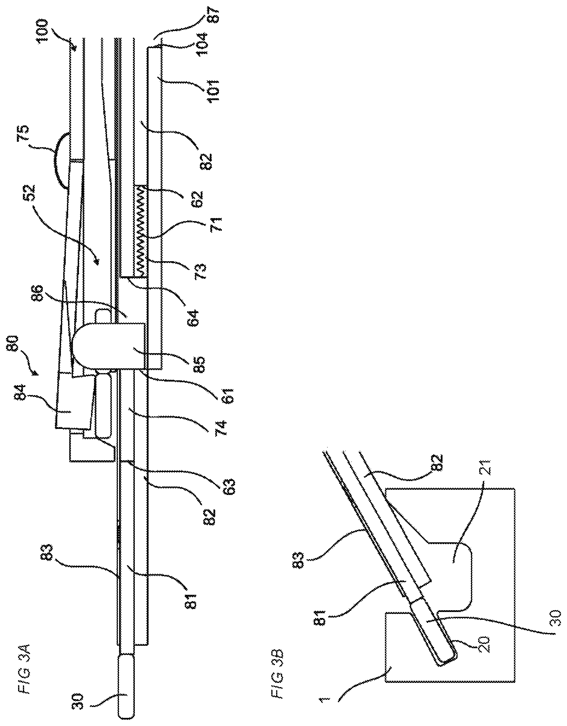
FIGS. 3A-3B show a schematic drawing of an enlargement of a device in a cross-section, according to an embodiment of the invention, in a position corresponding to FIG. 1E
FIGS. 4A-4D show embodiments of the tongue according to embodiments of the invention.
FIGS. 5A-5D show an embodiment of the tongue according to an embodiment of the invention.
FIGS. 6A-6D show embodiments of the panel according to embodiments of the invention.
DESCRIPTION OF EMBODIMENTS
Specific embodiments of the invention will now be described with reference to the accompanying drawings. This invention may, however, be embodied in many different forms and should not be construed as limited to the embodiments set forth herein; rather, these embodiments are provided so that this disclosure will be thorough and complete, and will fully convey the scope of the invention to those skilled in the art. The terminology used in the detailed description of the embodiments illustrated in the accompanying drawings is not intended to be limiting of the invention. In the drawings, like numbers refer to like elements.
Embodiments of the method for inserting a tongue into an insertion groove and a device for the method are shown that may have an improved efficiency. The embodiments may be advantageous for inserting the tongue into an insertion groove at an edge of a panel while displacing the panel in a panel feeding direction. The embodiments may be particularly advantageous for inserting the tongue into an insertion groove comprising a side wall in the feeding direction and/or into an insertion groove in an edge groove comprising a side wall in the feeding direction.
An embodiment of the method is shown in FIGS. 1A-1H. The method comprises inserting a tongue 30 in an insertion groove 20 in a panel by a device, wherein the method comprises: displacing a tongue guiding device in a first direction 91 by displacing a puncher 81 in the first direction 91, and displacing a tongue 30 between a first part 83 and a second part 82 of the tongue guiding device and into an insertion groove 20 in panel by further displacing the puncher 81.
The method may comprise displacing the puncher 81 in the first direction 91 a longer distance than said displacing of the tongue guiding device. FIG. 1A shows an initial position of the puncher 81 and the guiding device. The guiding device is displaced in the first position until it has reached an outer end position shown in FIG. 1D, the puncher continues to be displaced until it has reached an outer end position shown in FIG. 1E.
The method may comprise displacing the first part 83 of the tongue guiding device a longer distance in the first direction 91 than the second part 82 of the guiding device. The first part and the second part may have the same outer end position, which is shown in FIG. 1D. The first part may have an initial position which is at a distance from an initial position of the second part, see FIG. 1A. The distance may be essentially the same or longer than a width of the tongue 30.
The method may comprise displacing the puncher 81 and the tongue guiding device in a second direction 92, which is opposite the first direction 91, towards initial positions of the puncher 81 and the tongue guiding device, respectively. A beginning of a displacement of the puncher 81 in the second direction is shown FIG. 1F. A beginning of a displacement of the guiding device in the second direction is shown FIG. 1G, i.e., after the beginning of a displacement of the puncher 81.
The method may comprise displacing 93 a tongue queue stopper 84 by the tongue guiding device, preferably by a protruding part 85, and feeding a new tongue 30''', as is shown in FIG. 1D. The method may comprise displacing the tongue queue stopper in an opposite direction 94 when the tongue guiding device is being displaced in the second direction, see FIG. 1G.
The method may comprise displacing the new tongue 30''' into the tongue guiding device when a first part 83 of the tongue guiding device has reached, or is about to reach, its initial position, as is shown in FIG. 1 H.
The method may comprise displacing the puncher 81 and the tongue guiding device in relation to a tongue queue device 100.
The method may comprise displacing the puncher 81 in the first direction 91 and preferably in a second direction 92, which is opposite to the first direction, by a motor (not shown), such as an electric motor or a pneumatic motor.
An embodiment of the device 80 in the initial position is shown in FIG. 2 and an outer end position is shown in FIG. 3A and FIG. 3B. FIG. 3B shows an embodiment of the panel 1 comprising an insertion groove 20 in an edge groove 21, the tongue 30, the puncher 81 and the first part 83 and the second part 82 of the tongue guiding device. The tongue guiding device is displaced to a position close to an opening of the insertion groove. The distance between the guiding device and the opening is preferably about 1 mm or may be in the range of about 0.5 mm to about 2 mm. The device comprises a tongue guiding device, which is displaceable in a first direction 91, and a puncher 81 which is configured to displace a tongue 30 between a first part 83 and a second part 82, into an inserting groove 20 in a panel, wherein the tongue guiding device is configured to be displaced by the puncher, which is displaceable in the first direction 91.
FIGS. 2 and 3A shows an attachment device 88 for coupling the puncher 81 to the motor by a coupling element. The coupling element may comprise a spring element.
The puncher, the first part and the second part are preferably coupled together by spring elements (71,72) such that desired positions of the puncher, the first part and the second part are obtained.
The puncher 81 may be coupled to a coupling device 86 by a second spring 72.
The first part 83 of the tongue guiding device may be attached to the coupling device 86.
The first part 83 of the tongue guiding device may not be displaceable relative the coupling device 86.
The second part 82 of the tongue guiding device may be attached to the coupling device 86. The second part 82 of the tongue guiding device may be coupled to the coupling device by a first spring 71.
An embodiment of the device 80 may comprise a fixed structural element 101 comprising a first guiding groove 102. A protruding part 87 of the second part 82 of the guiding device may be configured to be displaceable between a first surface 103 of the first guiding groove 102 and an opposite second surface 104 of the first guiding groove.
The puncher 81 may be configured to drive the protruding part, via the second spring 72, the coupling device 86 and the first spring 71, between the first surface 103 and the second surface 104 of the first guiding groove 102. The first surface 103 and the second surface 104 may determine the displacement range, in the first direction 91 and the second direction 92, respectively, of the second part 82 of the guiding device.
The second part 82 of the tongue guiding device may comprise a second guiding groove 73 comprising a first surface 61 and an opposite second surface 62. The coupling device 86 may be displaceable relative the second part 82 of the tongue guiding device. The first surface 61 and the opposite second surface 62 may determine the displacement range, in the first direction 91 and the second direction 92, respectively, of the coupling device 86 relative the second part 82 of the tongue guiding device.
The puncher 81 may comprise a third guiding groove 74 comprising a first surface 63 and an opposite second surface 64. The puncher 81 may be displaceable relative the coupling device 86.
The first surface 63 and the opposite second surface 64 of the third guiding groove 74 may determine the displacement range, in the first direction 91 and the second direction 92, respectively, of the puncher 81 relative the coupling device 86.
The coupling device 86 is in the initial position shown in FIG. 2 in contact with the second surface 62 of the second guiding groove 73 and the first spring 71 is compressed.
The protruding part of the second part 82 of the guiding device is in the initial position shown in FIG. 2 in contact with the first surface 103 of the first guiding groove 102.
The coupling device 86 is in the outer end position shown in FIG. 3A in contact the second surface 64 of the third guiding groove 74 the second spring 71 is compressed.
The protruding part 87 of the second part 82 of the guiding device is in the outer end position shown in FIG. 3A in contact with the second surface 104 of the first guiding groove 102.
The puncher 81 may be displaceable a longer distance in the first direction than the tongue guiding device.
The first part 83 of the tongue guiding device may be displaceable a longer distance in the first direction than the second part 82 of the guiding device.
The puncher 81 and the tongue guiding device may be displaceable in a second direction 92, which is opposite the first direction 91, towards initial positions of the puncher 81 and the tongue guiding device, respectively.
The device may comprise a displaceable tongue queue stopper 84 for controlling a feeding of a new tongue, the tongue queue stopper 84 is preferably configured to cooperate with a protruding part 85 on the tongue guiding device.
The protruding part 85 which is configured to displace the tongue queue stopper 84 may be attached to the coupling device 86. The protruding part 85 may not be displaceable relative the coupling device 86.
The device may be configured such that a new tongue 30''' is displaced into the tongue guiding device when the first part 83 of the tongue guiding device has reached, or is about to reach, its initial position. The new tongue and tongues in the tongue queue are preferably identical or essentially identical to the tongue.
The puncher 81 and the tongue guiding device may be displaceable in relation to a tongue queue device 100.
The device preferably comprises a spring element between a power unit, such as a motor (not shown), and the puncher 81. The spring element may have the advantage that the device and/or the panel are not damaged in case any one of the panel, the insertion groove and the puncher is/are positioned in a wrong position(s).
The device may comprise a motor (not shown), such as an electric motor or a pneumatic motor, configured to drive the puncher 81 in the first direction 91 and preferably in a second direction 92, which is opposite to the first direction.
The tongue queue stopper 84 is preferably coupled to the device by a spring element 75. The tongue queue stopper may be displaced in a one direction by cooperation with the tongue guiding device and displaced in a return direction by the spring element.
An advantage of this embodiment of the device may be that only one motor is required to drive the puncher, the guiding device and the tongue queue stopper.
Embodiments of the tongue 30, which may be displaceable in an insertion groove 20, see FIGS. 6A-6D, are shown in FIGS. 4A-4D. A first embodiment of the tongue, which is shown in FIG. 3A-3B, comprises bendable protruding parts 31 at a first long edge of the tongue. The first embodiment is shown in a relaxed state in FIG. 4A and in a compressed state in FIG. 4B. A second long edge of the tongue is preferably essentially straight. The first embodiment may be inserted into the insertion groove with the bendable protruding parts facing towards a bottom of the insertion groove and the second edge extending beyond an opening of the insertion groove. A second embodiment of the tongue, which is shown in FIG. 4C in a relaxed state, is of an elongated shape and flexible. The second embodiment comprises a recess 37 at a first long edge of the tongue and a second edge which is essentially straight. The recess is decreased in a compressed state of the second embodiment. The second embodiment may be inserted into the insertion groove with the recess 37 facing towards a bottom of the insertion groove and the second edge extending beyond an opening of the insertion groove. A third embodiment of the tongue, which is shown in FIG. 4D, comprises a first part 38, which is flexible and configured to be compressed, and a second part 39 which is rigid. The first part may be arranged in the insertion groove and the second part may partly extend beyond an opening of the insertion groove.
The tongue may be configured as any of the embodiments of the displaceable tongue disclosed in, e.g., WO 2006/043893 and WO 2007/015669, the entire contents of which are hereby expressly incorporated herein by reference.
The tongue may be flexible and made of, e.g., a polymer and preferably comprising a reinforcement material, such as a fibre, e.g., fiberglass.
Another embodiment of the tongue 30 is shown in FIGS. 5A-5D. The tongue is of an elongated shape and comprises a first short edge 34, an opposite second short edge 36, first long edge and a second long edge 32. FIG. 5D shows an enlargement of the encircled area A indicated in FIG. 5A. The tongue comprises several bendable parts 31 at the first long edge and a groove 33 at each bendable part 31. The tongue comprises a polymer material and is preferably produced by injection moulding. The bendable part 31 is configured to be pushed into the groove 33 in a compressed state of the tongue.
FIG. 5A shows an embodiment of tongue which is connected to several tongues (not shown) in a tongue blank by a first rail 35 at the first short edge 34 and by a second rail 37 at the second short edge 36. The first rail and the second rail extend in a length direction perpendicular to the tongue. The tongue may be connected to the first rail and/or the second rail, which may be casting gates, by a first and a second casting gate 41,42, respectively.
FIG. 5B and FIG. 5C show the tongue 30 in a cross cut view. The tongue is in FIG. 5B in a relaxed state an in FIG. 5C in a compressed state. A distance between an outer part of the bendable part 31 and the second long edge 32 is shorter in the compressed state compared to in the relaxed state.
The tongue is preferably configured to be inserted into an insertion groove of a panel for locking the panel to an adjacent panel.
FIGS. 6A-6D shows embodiments of the panel 1, each comprising an embodiment of the tongue 30 inserted in an embodiment of the insertion groove 20, connected to an adjacent panel 2. The embodiments of the panel shown in FIGS. 6A-6D may be furniture panels. The embodiment of the panel shown in FIG. 6C may also be a floor panel.
FIG. 6A shows the panel 1 arranged perpendicular to an adjacent panel 2 and locked to the adjacent panel in a first direction and in a second direction, which is perpendicular to the first direction. The panel comprising an edge groove 21 at an upper surface of the panel. The edge groove 21 is of a longitudinal shape and extends along an edge of the panel 1. The edge groove comprising said insertion groove 20, which is extending along the edge groove, comprising said tongue 30. The adjacent panel comprises an edge tongue 22 which comprises a tongue groove 10 extending along an edge of the adjacent panel. The tongue 30 is configured to cooperate with the tongue groove 10 for locking together the panel 1 with the adjacent panel 2 in the first direction. The edge tongue 22 is configured to cooperate with the edge groove 21 for locking together the panel 1 with the adjacent panel 2 in the second direction.
FIG. 6B shows the panel 1 arranged perpendicular to an adjacent panel 2 and locked to the adjacent panel in a first direction and in a second direction, which is perpendicular to the first direction. The adjacent panel comprising an edge groove 21 at an upper surface of the adjacent panel. The edge groove 21 is of a longitudinal shape and extends along an edge of the adjacent panel 1. The edge groove comprises a tongue groove 10. The panel comprises an edge tongue 22 which comprises said insertion groove 20 comprising said tongue 30. The insertion groove is extending along the edge tongue. The tongue 30 is configured to cooperate with the tongue groove 10 for locking together the panel 1 with the adjacent panel 2 in the first direction. The edge tongue 22 is configured to cooperate with the edge groove 21 for locking together the panel 1 with the adjacent panel 2 in the second direction.
FIG. 6C shows the panel 1 arranged parallel to an adjacent panel 2 and locked to the adjacent panel in a first direction and in a second direction, which is perpendicular to the first direction. The panel comprising said insertion groove 20 which is extending along an edge of the panel. The edge comprises a strip protruding from the edge and the strip comprises an upwardly protruding locking element. The adjacent panel 2 comprises a tongue groove 10 extending along an adjacent edge of the adjacent panel 2. The adjacent edge comprises a locking groove with an opening facing downwards. The tongue 30 is configured to cooperate with the tongue groove 10 for locking the panel to the adjacent panel in a first direction and the locking element is configured to cooperate with the locking groove for locking the panel to the adjacent panel in the second direction. An embodiment of the said first and second panel comprises the insertion groove 20 at the adjacent edge of the adjacent panel and the tongue groove 10 at the edge of the panel.
FIG. 6D shows an embodiment of the panel and the adjacent panel shown in FIG. 6A in a 3D-view. The edge tongue 22 is extending along the edge 4 of the adjacent panel and ends before an adjacent edge 6 of the adjacent panel 2. The edge groove 21 is extending along the edge 3 of the panel 1 and ends at a side wall 23 before an adjacent edge of the 5 of the panel 1.
A core material of embodiments of the panel and the adjacent panel described above may comprises a wood fibre based board, such as a HDF, MDF, plywood, solid wood or particleboard, or a reinforced plastic board or a wood fibre composite board. The core may be provided with a decorative layer.
EMBODIMENTS
1. A method for inserting a tongue in an insertion groove in a panel by a device, wherein the method comprises: displacing a tongue guiding device in a first direction (91) by displacing a puncher (81) in the first direction (91), and displacing a tongue (30) between a first part (83) and a second part (82) of the tongue guiding device and into an insertion groove (20) in panel by further displacing the puncher (81).
2. The method as in embodiment 1, comprising displacing the puncher (81) in the first direction (91) a longer distance than said displacing of the tongue guiding device.
3. The method as in embodiment 1 or 2, comprising displacing the first part (83) of the tongue guiding device a longer distance in the first direction (91) than the second part (82) of the guiding device.
4. The method as in any of the embodiments 1-3, comprising displacing the puncher (81) and the tongue guiding device in a second direction (92), which is opposite the first direction (91), towards initial positions of the puncher (81) and the tongue guiding device, respectively.
5. The method as in embodiment 4, comprising displacing (93) a tongue queue stopper (84) by the tongue guiding device, preferably by a protruding part (85), and feeding a new tongue (30''').
6. The method as in embodiment 5, comprising displacing the new tongue (30''') into the tongue guiding device when a first part (83) of the tongue guiding device has reached, or is about to reach, its initial position.
7. The method as in any one of embodiments 1-6, comprising displacing the puncher (81) and the tongue guiding device in relation to a tongue queue device (100).
8. The method as in any one of the embodiments 1-7, comprising displacing the puncher (81) in the first direction (91), and preferably in a second direction (92), which is opposite to the first direction, by a motor, such as an electric motor or a pneumatic motor.
9. A device for inserting a tongue in an inserting groove in a panel, wherein the device comprises a tongue guiding device, which is displaceable in a first direction (91), and a puncher (81), which is configured to displace a tongue (30) between a first part (83) and a second part (82), into an inserting groove (20) in a panel, wherein the tongue guiding device is configured to be displaced by the puncher, which is displaceable in the first direction (91).
10. The device as in embodiment 9, wherein the puncher (81) is displaceable a longer distance in the first direction than the tongue guiding device.
11. The device as in embodiment 9 or 10, wherein the first part (83) of the tongue guiding device is displaceable a longer distance in the first direction than the second part (82) of the guiding device.
12. The device as in any of the embodiments 9-11, wherein the puncher (81) and the tongue guiding device are displaceable in a second direction (92), which is opposite the first direction (91), towards initial positions of the puncher (81) and the tongue guiding device, respectively.
13. The device as in embodiment 12, wherein the device comprises a displaceable tongue queue stopper (84) for controlling a feeding of a new tongue, the tongue queue stopper (84) is preferably configured to cooperate with a protruding part (85) on the tongue guiding device.
14. The device as in any one of the embodiments 9-13, wherein the device is configured such that a new tongue (30''') is displaced into the tongue guiding device when the first part (83) of the tongue guiding device has reached, or is about to reach, its initial position.
15. The device as in any one of the embodiments 9-14, wherein the puncher (81) and the tongue guiding device are displaceable in relation to a tongue queue device (100).
16. The device as in any one of the embodiments 9-15, wherein device comprises a motor, such as an electric motor or a pneumatic motor, configured to drive the puncher (81) in the first direction (91), and preferably in a second direction (92), which is opposite to the first direction.
* * * * *
D00000
D00001
D00002
D00003
D00004
D00005
D00006
D00007
XML
uspto.report is an independent third-party trademark research tool that is not affiliated, endorsed, or sponsored by the United States Patent and Trademark Office (USPTO) or any other governmental organization. The information provided by uspto.report is based on publicly available data at the time of writing and is intended for informational purposes only.
While we strive to provide accurate and up-to-date information, we do not guarantee the accuracy, completeness, reliability, or suitability of the information displayed on this site. The use of this site is at your own risk. Any reliance you place on such information is therefore strictly at your own risk.
All official trademark data, including owner information, should be verified by visiting the official USPTO website at www.uspto.gov. This site is not intended to replace professional legal advice and should not be used as a substitute for consulting with a legal professional who is knowledgeable about trademark law.