Anti-reverse rotation device of power-driven shoe device
Zhang , et al. March 2, 2
U.S. patent number 10,933,298 [Application Number 16/346,860] was granted by the patent office on 2021-03-02 for anti-reverse rotation device of power-driven shoe device. This patent grant is currently assigned to Nimbus Robotics, Inc.. The grantee listed for this patent is Nimbus Robotics, Inc.. Invention is credited to Jianjun Li, Dongliang Song, Bojie Xu, Jiancheng Zhang.

| United States Patent | 10,933,298 |
| Zhang , et al. | March 2, 2021 |
Anti-reverse rotation device of power-driven shoe device
Abstract
Disclosed is an anti-reverse rotation device of a power-driven shoe device, the power-driven shoe device comprising a shoe sole (1), wherein a group of front wheels (2) and a group of rear wheels (3) are arranged on a lower side surface of the shoe sole (1); and the front wheels (2) are connected to an anti-reverse rotation mechanism for preventing the front wheels (2) from rotating in reverse. The anti-reverse rotation mechanism can prevent the front wheels (2) from rotating in reverse, and as such, when the front wheels (2) are independently in contact with the ground and a certain included angle is formed between a shoe body and the ground, the situation of the front wheels (2) applying a certain pressure to the ground and the front wheels (2) rotating in reverse, such that a lifted foot moves backwards, thereby causing a person to fall down, is avoided, and walking safety is improved.
| Inventors: | Zhang; Jiancheng (JiangBei NingBo, CN), Xu; Bojie (JiangBei NingBo, CN), Li; Jianjun (JiangBei NingBo, CN), Song; Dongliang (JiangBei NingBo, CN) | ||||||||||
|---|---|---|---|---|---|---|---|---|---|---|---|
| Applicant: |
|
||||||||||
| Assignee: | Nimbus Robotics, Inc.
(Pittsburgh, PA) |
||||||||||
| Family ID: | 1000005392159 | ||||||||||
| Appl. No.: | 16/346,860 | ||||||||||
| Filed: | August 3, 2017 | ||||||||||
| PCT Filed: | August 03, 2017 | ||||||||||
| PCT No.: | PCT/CN2017/000501 | ||||||||||
| 371(c)(1),(2),(4) Date: | May 01, 2019 | ||||||||||
| PCT Pub. No.: | WO2018/082194 | ||||||||||
| PCT Pub. Date: | May 11, 2018 |
Prior Publication Data
| Document Identifier | Publication Date | |
|---|---|---|
| US 20200061444 A1 | Feb 27, 2020 | |
Foreign Application Priority Data
| Nov 1, 2016 [CN] | 201610937116.7 | |||
| Current U.S. Class: | 1/1 |
| Current CPC Class: | A63C 17/0006 (20130101); A63C 17/12 (20130101) |
| Current International Class: | A63C 17/12 (20060101); A63C 17/00 (20060101) |
References Cited [Referenced By]
U.S. Patent Documents
| 833100 | October 1906 | Wells |
| 1672700 | June 1928 | Vass |
| 1801205 | April 1931 | Mirick |
| 2857008 | October 1958 | Pirrello |
| 3392986 | July 1968 | Ryan |
| 4334690 | June 1982 | Klamer |
| 4417737 | November 1983 | Suroff |
| 4553767 | November 1985 | Robjent |
| RE32346 | February 1987 | Klamer |
| 4932676 | June 1990 | Klamer |
| 5056802 | October 1991 | Piotrowski |
| 5236058 | August 1993 | Yamet |
| 5400484 | March 1995 | Gay |
| 5730241 | March 1998 | Shyr |
| 5797466 | August 1998 | Gendle |
| 6059062 | May 2000 | Staelin |
| 6322088 | November 2001 | Klamer |
| 6497421 | December 2002 | Edgerley |
| 6517091 | February 2003 | Fisher |
| 6645126 | November 2003 | Martin et al. |
| 7163210 | January 2007 | Rehkemper |
| 7204330 | April 2007 | Lauren |
| 9027690 | May 2015 | Chavand |
| 9295302 | March 2016 | Reed et al. |
| 9925453 | March 2018 | Tuli |
| 10456698 | October 2019 | Chen |
| 2001/0022433 | September 2001 | Chang |
| 2003/0047893 | March 2003 | Pahis |
| 2003/0141124 | July 2003 | Mullet |
| 2004/0239056 | December 2004 | Cho |
| 2005/0046139 | March 2005 | Guan |
| 2006/0027409 | February 2006 | Adams |
| 2007/0090613 | April 2007 | Lyden |
| 2007/0273110 | November 2007 | Brunner |
| 2009/0120705 | May 2009 | McKinzie |
| 2012/0285756 | November 2012 | Treadway |
| 2013/0025955 | January 2013 | Chavand |
| 2013/0123665 | May 2013 | Mariani et al. |
| 2013/0274640 | October 2013 | Butters et al. |
| 2014/0196757 | July 2014 | Goffer |
| 2015/0196403 | July 2015 | Kim et al. |
| 2016/0045385 | February 2016 | Aguirre-Ollinger et al. |
| 2016/0113831 | April 2016 | Hollander |
| 2016/0250094 | September 2016 | Amundson et al. |
| 2016/0331557 | November 2016 | Tong et al. |
| 2017/0055880 | March 2017 | Agrawal et al. |
| 2017/0181917 | June 2017 | Ohta et al. |
| 2017/0182397 | June 2017 | Zhang |
| 2017/0259811 | September 2017 | Coulter et al. |
| 2017/0296116 | October 2017 | McCarthy et al. |
| 2019/0314710 | October 2019 | Zhang |
| 2019/0351315 | November 2019 | Li |
| 2020/0061444 | February 2020 | Zhang |
| 2020/0061445 | February 2020 | Zhang et al. |
| 2020/0129843 | April 2020 | Zhang et al. |
| 2020/0129844 | April 2020 | Zhang et al. |
| 2759524 | Feb 2006 | CN | |||
| 201423154 | Mar 2010 | CN | |||
| 201565096 | Sep 2010 | CN | |||
| 101912680 | Dec 2010 | CN | |||
| 101912681 | Dec 2010 | CN | |||
| 102167117 | Aug 2011 | CN | |||
| 102805928 | Dec 2012 | CN | |||
| 203389316 | Jan 2014 | CN | |||
| 104689559 | Jun 2015 | CN | |||
| 204364838 | Jun 2015 | CN | |||
| 204395401 | Jun 2015 | CN | |||
| 105214299 | Jan 2016 | CN | |||
| 106039689 | Oct 2016 | CN | |||
| 205627021 | Oct 2016 | CN | |||
| 106390428 | Feb 2017 | CN | |||
| 106390430 | Feb 2017 | CN | |||
| 106582003 | Apr 2017 | CN | |||
| 0686412 | Dec 1995 | EP | |||
| 0834337 | Apr 1998 | EP | |||
| 0894515 | Feb 1999 | EP | |||
| 3629925 | Apr 2020 | EP | |||
| 2005-81038 | Mar 2005 | JP | |||
| 2018082192 | May 2018 | WO | |||
| 2018082193 | May 2018 | WO | |||
| 2018082194 | May 2018 | WO | |||
| 2018082195 | May 2018 | WO | |||
| 2019014152 | Jan 2019 | WO | |||
| 2019014154 | Jan 2019 | WO | |||
| 2019212995 | Nov 2019 | WO | |||
Other References
|
International Search Report and Written Opinion for PCT/CN2017/000501 dated Nov. 3, 2017. cited by applicant . International Search Report and Written Opinion for PCT/CN2017/000499 dated Oct. 20, 2017. cited by applicant . International Search Report and Written Opinion for PCT/CN2017/000502 dated Oct. 13, 2017. cited by applicant . International Search Report and Written Opinion for PCT/US2018/041343 dated Sep. 7, 2018. cited by applicant . International Search Report and Written Opinion for PCT/US2018/041345 dated Sep. 7, 2018. cited by applicant . International Search Report and Written Opinion for PCT/US2019/029742 dated Aug. 26, 2019. cited by applicant . International Search Report and Written Opinion for PCT/CN2017/000500 dated Oct. 20, 2017. cited by applicant. |
Primary Examiner: Gurari; Erez
Attorney, Agent or Firm: Troutman Pepper Hamilton Sanders LLP
Claims
The invention claimed is:
1. A power shoe device comprising: a shoe sole comprising a shoe heel part and a shoe forefoot part, wherein a group of front wheels is mounted on the shoe forefoot part, wherein a group of rear wheels is mounted on the shoe heel part, and wherein the group of front wheels and the group of rear wheels are each disposed on the lower side surface of the shoe sole; wherein the shoe heel part and the shoe forefoot part are in rotatable connection with each other; and wherein the group of front wheels are connected with an anti-reverse rotation mechanism comprising a rotating shaft connected with the group of front wheels, a ratchet wheel fixed on the rotating shaft, and a pawl matched with the ratchet wheel for preventing the group of front wheels from being inverted.
2. The power shoe device according to claim 1, further comprising a group of middle wheels, a motor, and a transmission device, wherein the motor is further disposed at the lower part of the shoe sole; and wherein the output end of the motor is connected with the transmission device which is in driving connection with at least one of the group of middle wheels and the group of rear wheels.
3. The power shoe device according to claim 1, further comprising a group of middle wheels, a motor, and a transmission device, characterized in that the motor is further disposed at the lower part of the shoe sole; and wherein the output end of the motor is connected with the transmission device which is simultaneously in driving connection with the group of middle wheels and the group of rear wheels.
Description
TECHNICAL FIELD
The present application relates to Anti-reverse rotation devices of power shoe devices, and belongs to the technical field of transportation tools.
BACKGROUND ART
With the further growth of the urban population, traffic jam has become the nuisance of every main city. Although public transportation is a very effective solution to the traffic jam, a last kilometer problem, that is, a relatively long final walking distance, still remains, which is one of the factors hindering the building of a perfect bus system. Traditional roller skates can solve the above-mentioned problem to a certain extent, and there are various electric transportation tools on the market, such as electric roller skates appearing recently, which are the solutions to the last kilometer problem.
However, the traditional roller skates and the recent electric roller skates both have one problem that: when lifting up the shoes, people often lift up shoe heels first and then forefoot parts. In this process, front rollers of the shoes are in contact with the ground alone, and shoe bodies would form certain included angles with the ground; at the moment, if the front rollers apply a certain pressure onto the ground, the front rollers would be inverted and make the lifted shoe heels to move backwards, resulting in falling over of people, so that these roller skates are very unsafe to slide on the road.
SUMMARY OF THE INVENTION
In view of the shortcomings in the prior art, the present application provides Anti-reverse rotation devices of power shoe devices, by which, front wheels of the present application would not be inverted, thus achieving an effect of preventing people from falling over.
In order to solve the above-mentioned problem, the present application provides the following technical solution: Anti-reverse rotation devices of power shoe devices, each of which includes a shoe sole. A group of front wheels and a group of rear wheels are disposed on the lower side surface of the shoe sole. Each Anti-reverse rotation device is characterized in that the front wheels are connected with an Anti-reverse rotation mechanism for preventing the front wheels from being inverted. The Anti-reverse rotation mechanisms of the present application can prevent the front wheels from being inverted, so that when the front wheels are in contact with the ground alone, and shoe bodies forms certain included angles with the ground, the phenomenon that people fall over by backward movement of lifted shoe heels if the front wheels apply a certain pressure onto the ground and are inverted is avoided, and the walking safety is improved.
Specifically, the Anti-reverse rotation mechanism includes a rotating shaft connected with the front wheels, a ratchet wheel fixed on the rotating shaft, and a pawl matched with the ratchet wheel.
In order to achieve a better technical effect, a further technical measure also includes that: each of the shoe soles consists of a shoe heel part and a shoe forefoot part. The shoe heel part and the shoe forefoot part are in rotatable connection with each other. The front wheels are mounted on the shoe forefoot part, and a group of middle wheels are further disposed on the shoe heel part. Because the shoe heel parts and the shoe forefoot parts may rotate relatively to accord with the walking posture that a user lifts up heels first and then forefoot parts during walking, the user can keep a normal walking posture during use of the present application. In the normal walking posture, it is easier for people to master the use the present application. Moreover, the present application may be suitable for complicated urban roads, such as switching sidewalks and striding puddles, and its practicability is greatly improved. Furthermore, people can keep at least four rotating wheels on the ground no matter if the shoe heels are on or off the ground during walking, so as to guarantee their stability and improve their walking safety on the road.
A motor is further disposed at the lower part of each of the shoe soles. The output end of the motor is connected with a transmission device which is in driving connection with the middle wheels or the rear wheels. In this solution, by the adoption of the motor for driving, the burden on people during walking can be relieved, and the walking speed is increased.
A motor is further disposed at the lower part of each of the shoe soles. The output end of the motor is connected with a transmission device which is in driving connection with the middle wheels and the rear wheels. In this solution, the motor simultaneously drives the two groups of rotating wheels, namely the middle wheels and the rear wheels, so that when the rear wheels are lifted up, the middle wheels may still provide forward moving power.
Compared with the prior art, the present application has the following beneficial effects that: the Anti-reverse rotation mechanisms of the present application can prevent the front wheels from being inverted, so that when the front wheels are in contact with the ground alone, and the shoe bodies form certain included angles with the ground, the phenomenon that people fall over by backward movement of the lifted shoe heels if the front wheels apply a certain pressure onto the ground and are inverted is avoided, and the walking safety is improved.
BRIEF DESCRIPTION OF THE DRAWINGS
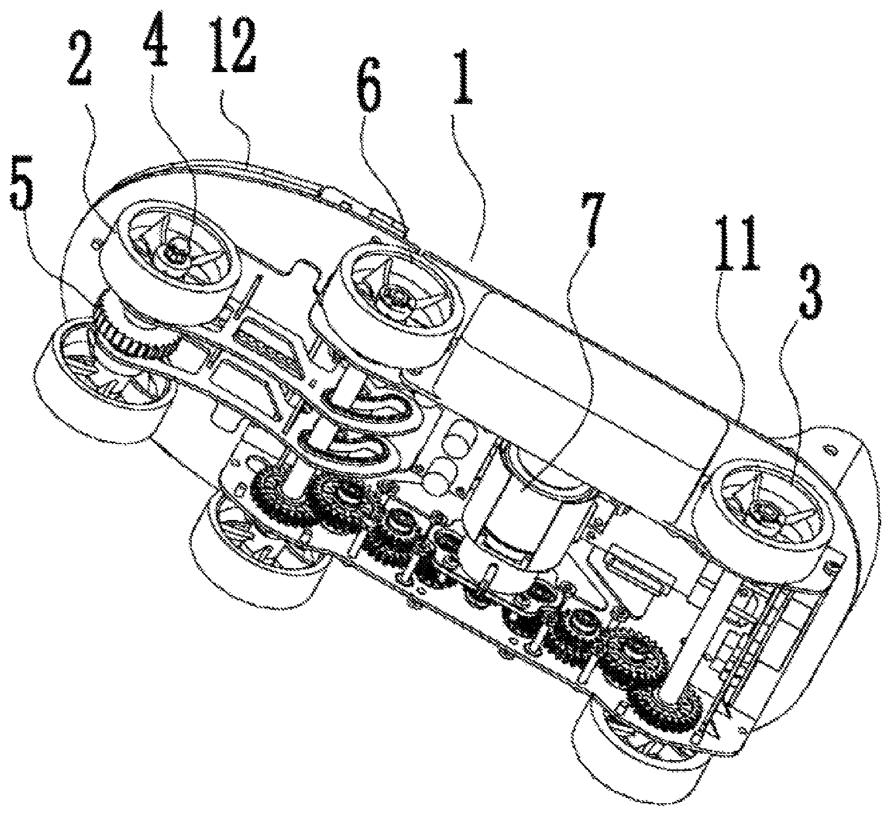
FIG. 1 is a schematic diagram of a structure of Embodiment 1 of the present application.
DETAILED DESCRIPTION OF THE INVENTION
A further detailed description will be made below to the present application in combination with accompanying drawings and specific implementation modes.
Embodiment 1
With reference to FIG. 1, Anti-reverse rotation devices of power shoe devices are provided, each of which includes a shoe sole 1. A group of front wheels 2 and a group of rear wheels 3 are disposed on the lower side surface of the shoe sole 1. Each Anti-reverse rotation device is characterized in that the front wheels 2 are connected with an Anti-reverse rotation mechanism for preventing the front rollers from being inverted.
Wherein, the Anti-reverse rotation mechanism includes a rotating shaft 4 connected with the front wheels 2, a ratchet wheel 5 fixed on the rotating shaft 4, and a pawl matched with the ratchet wheel 5.
The shoe sole 1 consists of a shoe heel part 11 and a shoe forefoot part 12. The shoe heel part 11 and the shoe forefoot part 12 are in rotatable connection with each other. The front wheels 2 are mounted on the shoe forefoot part 12, and a group of middle wheels 6 are further disposed on the shoe heel part 11. A motor 7 is further disposed at the lower part of the shoe sole 1. The output end of the motor 7 is connected with a transmission device which is simultaneously in driving connection with the middle wheels 6 and the rear wheels 3.
Embodiment 2
In this embodiment (FIGURE is omitted), a motor 7 is further disposed at the lower part of the shoe sole 1. The output end of the motor 7 is connected with a transmission device which is in driving connection with the middle wheels 6 or the rear wheels 3.
The rest part is the same as that of Embodiment 1, so that the descriptions thereof are omitted herein.
* * * * *
D00000
D00001
XML
uspto.report is an independent third-party trademark research tool that is not affiliated, endorsed, or sponsored by the United States Patent and Trademark Office (USPTO) or any other governmental organization. The information provided by uspto.report is based on publicly available data at the time of writing and is intended for informational purposes only.
While we strive to provide accurate and up-to-date information, we do not guarantee the accuracy, completeness, reliability, or suitability of the information displayed on this site. The use of this site is at your own risk. Any reliance you place on such information is therefore strictly at your own risk.
All official trademark data, including owner information, should be verified by visiting the official USPTO website at www.uspto.gov. This site is not intended to replace professional legal advice and should not be used as a substitute for consulting with a legal professional who is knowledgeable about trademark law.